JP2018052182A - Electronic control system for vehicles - Google Patents
Electronic control system for vehicles Download PDFInfo
- Publication number
- JP2018052182A JP2018052182A JP2016187689A JP2016187689A JP2018052182A JP 2018052182 A JP2018052182 A JP 2018052182A JP 2016187689 A JP2016187689 A JP 2016187689A JP 2016187689 A JP2016187689 A JP 2016187689A JP 2018052182 A JP2018052182 A JP 2018052182A
- Authority
- JP
- Japan
- Prior art keywords
- control unit
- element control
- unit
- independent
- actuator
- Prior art date
- Legal status (The legal status is an assumption and is not a legal conclusion. Google has not performed a legal analysis and makes no representation as to the accuracy of the status listed.)
- Granted
Links
Images
Landscapes
- Hardware Redundancy (AREA)
Abstract
【課題】要素制御ユニットに異常が発生した場合でも車両を走行させることが可能な車両用電子制御システムを提供する。
【解決手段】車両用電子制御システムは、アクチュエータβの動作を制御して所定の要素制御を行う要素制御ユニット2と、特定の制御対象を持たない独立ユニット3と、を備え、独立ユニット3と要素制御ユニット2との間で通信を行うことができるように構成されており、独立ユニット3は、要素制御ユニット2に異常が発生した場合に、要素制御ユニット2の処理の少なくとも一部を行うことによりアクチュエータβの動作を制御する。
【選択図】図1An electronic control system for a vehicle capable of running a vehicle even when an abnormality occurs in an element control unit.
An electronic control system for a vehicle includes an element control unit that performs predetermined element control by controlling an operation of an actuator, and an independent unit that does not have a specific control target. The independent unit 3 is configured to be able to communicate with the element control unit 2, and the independent unit 3 performs at least a part of the process of the element control unit 2 when an abnormality occurs in the element control unit 2. Thus, the operation of the actuator β is controlled.
[Selection] Figure 1
Description
本発明は、車両用電子制御システムに係り、特にエンジン電子制御ユニット等の複数の要素制御ユニットを有する車両用電子制御システムに関する。 The present invention relates to a vehicle electronic control system, and more particularly to a vehicle electronic control system having a plurality of element control units such as an engine electronic control unit.
自動車等の車両では、近年、燃費や排ガス性能、安全性等の向上のために電子化が進んでおり、車両には、エンジン電子制御ユニットやトランスミッション電子制御ユニット(TCUとも言う。)等の種々の電子制御ユニットが搭載されるようになっている。なお、以下では、電子制御ユニット(Electric Control Unit)をECUと略して表す。 In recent years, vehicles such as automobiles have been digitized to improve fuel consumption, exhaust gas performance, safety, and the like, and various types of vehicles such as an engine electronic control unit and a transmission electronic control unit (also referred to as TCU) are included in the vehicle. The electronic control unit is installed. Hereinafter, an electronic control unit is abbreviated as ECU.
また、車両には、走行安定性の向上のためにスタビリティコントロールシステムや、車両の揺れを減少させたり安定させるためのボディスタビライザー等の装置、或いは、追突防止や車線逸脱防止等のための運転支援システム等も搭載されている。なお、以下では、上記の各ECUやシステム、装置等を総称して、要素制御ユニットという。そして、これらの要素制御ユニットは、通常、自らが制御する制御対象に関する情報を計測するための各種のセンサや制御対象に必要な動作等を行わせるためのアクチュエータを備えている。 The vehicle also has a stability control system to improve running stability, a device such as a body stabilizer to reduce or stabilize vehicle shake, or driving to prevent rear-end collisions and lane departures. A support system is also installed. In the following, each of the ECUs, systems, devices, etc. will be collectively referred to as an element control unit. These element control units are usually provided with various sensors for measuring information related to the control target controlled by the element control unit and actuators for causing the control target to perform necessary operations.
そして、これらの各要素制御ユニットは、互いに連携して制御を行う必要があることから、通信ネットワークを介して互いに接続されており、例えばCAN(Controller Area Network)等のプロトコルに基づいて互いに情報等の送受信を行いながら各要素制御ユニットが協調しながら各々の制御を行うように構成される場合が多い。 Since these element control units need to perform control in cooperation with each other, they are connected to each other via a communication network. For example, information and the like are mutually connected based on a protocol such as CAN (Controller Area Network). In many cases, each element control unit is configured to perform each control in cooperation with each other while transmitting and receiving.
このようなシステムについては、例えば特許文献1、2にそれぞれ発明が開示されている。すなわち、特許文献1では、各要素制御ユニットを結ぶ系統の異なる複数のネットワークの間に、データの中継機能を有する中継用のECUをいくつか設け、全てのネットワークに接続されたマネージャECUは、重要データの伝送経路に異常が発生した場合には、重要データの伝送経路を変更するとともに、処理負荷が一時的に大きくなった中継用のECUがあれば、それが中継するデータの一部を他の中継用のECUに中継させる車両用通信システムが開示されている。
For such a system, for example,
また、特許文献2には、ネットワークに接続された各ECUのうち、例えば走行モードECUをマスタ制御ユニット(ホスト)とし、他の複数のECUを従属制御ユニットとし、マスタ制御ユニットから複数の従属制御ユニットにシステム通信および制御の基本情報を送信してセットし、各制御ユニット間で制御情報を交信して車両の制御を行う車両制御のネットワークシステムが開示されている。
In
ところで、上記のように各要素制御ユニットが互いに接続されている車両用電子制御システムにおいて、ある要素制御ユニットに異常が発生すると、その要素制御ユニットが制御するアクチュエータが動かなくなったり、或いは異常な動作をするようになる場合があり得る。そして、アクチュエータが動かなくなったり異常な動作をすると、制御対象であるエンジンやトランスミッション等が動作しなくなったり異常な動作をするようになる可能性がある。 By the way, in the vehicle electronic control system in which the element control units are connected to each other as described above, if an abnormality occurs in a certain element control unit, the actuator controlled by the element control unit may stop moving or operate abnormally. It may happen that If the actuator does not move or operates abnormally, there is a possibility that the engine, transmission, or the like to be controlled does not operate or operates abnormally.
このような場合、異常が生じた要素制御ユニットを至急修理したり交換したりすること等が必要になる。そして、要素制御ユニットの修理や交換等は、通常、ディーラ等でしか行うことができないが、車両が動かなかったり異常な動きをするようでは、車両を走行させてディーラ等まで運ぶこともできなくなってしまい、車両をレッカー移動させなければならなくなる。 In such a case, it is necessary to urgently repair or replace the element control unit in which an abnormality has occurred. And repair and replacement of the element control unit can usually be done only by a dealer, but if the vehicle does not move or moves abnormally, it can not be moved to the dealer etc. And you have to move the vehicle tow.
しかし、このような状況でも、車両をディーラ等まで走行させることができれば、要素制御ユニットをディーラ等ですぐに修理したり交換したりすることが可能になる。また、車両をレッカー移動させなくても済むため、運転者にとって都合が良いと考えられる。 However, even in such a situation, if the vehicle can travel to a dealer or the like, the element control unit can be repaired or replaced immediately by the dealer or the like. In addition, since it is not necessary to move the vehicle tow truck, it is considered convenient for the driver.
本発明は、上記の点を鑑みてなされたものであり、要素制御ユニットに異常が発生した場合でも車両を走行させることが可能な車両用電子制御システムを提供することを目的とする。 The present invention has been made in view of the above points, and an object of the present invention is to provide a vehicle electronic control system capable of running a vehicle even when an abnormality occurs in an element control unit.
前記の問題を解決するために、請求項1に記載の発明は、車両用電子制御システムにおいて、
アクチュエータの動作を制御して所定の要素制御を行う要素制御ユニットと、
特定の制御対象を持たない独立ユニットと、
を備え、
前記独立ユニットと前記要素制御ユニットとの間で通信を行うことができるように構成されており、
前記独立ユニットは、前記要素制御ユニットに異常が発生した場合に、前記要素制御ユニットの処理の少なくとも一部を行うことにより前記アクチュエータの動作を制御することを特徴とする車両用電子制御システム。
In order to solve the above problem, the invention according to
An element control unit that performs predetermined element control by controlling the operation of the actuator;
An independent unit without a specific control target,
With
It is configured to be able to communicate between the independent unit and the element control unit,
The vehicle independent control system, wherein the independent unit controls the operation of the actuator by performing at least a part of the processing of the element control unit when an abnormality occurs in the element control unit.
請求項2に記載の発明は、請求項1に記載の車両用電子制御システムにおいて、 前記独立ユニットと前記要素制御ユニットとは、通信ネットワークで接続されていることを特徴とする。
The invention according to
請求項3に記載の発明は、請求項1または請求項2に記載の車両用電子制御システムにおいて、
前記要素制御ユニットは、メインCPUとサブCPUとを備えており、
前記サブCPUは、前記メインCPUに異常が発生した場合のフェール制御として、前記メインCPUに代わって前記要素制御ユニットの前記アクチュエータを動作させるための予め設定された制御を行うように構成されており、
前記独立ユニットは、前記要素制御ユニットの前記メインCPUに異常が発生した場合に、前記要素制御ユニットの前記メインCPUに代わって前記アクチュエータを動作させるために必要な制御パラメータを演算して前記サブCPUに送信して前記サブCPUに前記アクチュエータを動作させる前記フェール制御を行わせることで、当該要素制御ユニットの前記メインCPUに代わって前記アクチュエータの動作を制御することを特徴とする。
According to a third aspect of the present invention, in the vehicle electronic control system according to the first or second aspect,
The element control unit includes a main CPU and a sub CPU,
The sub CPU is configured to perform preset control for operating the actuator of the element control unit in place of the main CPU as fail control when an abnormality occurs in the main CPU. ,
The independent unit calculates a control parameter necessary for operating the actuator in place of the main CPU of the element control unit when an abnormality occurs in the main CPU of the element control unit, and calculates the sub CPU The operation of the actuator is controlled in place of the main CPU of the element control unit by causing the sub CPU to perform the fail control for operating the actuator.
請求項4に記載の発明は、請求項3に記載の車両用電子制御システムにおいて、前記サブCPUは、前記メインCPUに異常が発生したことを検知した場合に、前記独立ユニットに前記要素制御ユニットの前記メインCPUに異常が発生したことを報知することを特徴とする。 According to a fourth aspect of the present invention, in the vehicular electronic control system according to the third aspect, when the sub CPU detects that an abnormality has occurred in the main CPU, the independent control unit includes the element control unit. The main CPU is notified that an abnormality has occurred.
請求項5に記載の発明は、請求項1から請求項4のいずれか一項に記載の車両用電子制御システムにおいて、前記独立ユニットは、前記要素制御ユニットによる要素制御が正常に行われていない場合に、前記要素制御ユニットに異常が発生したと判断することを特徴とする。 According to a fifth aspect of the present invention, in the vehicle electronic control system according to any one of the first to fourth aspects, element control by the element control unit is not normally performed in the independent unit. In this case, it is determined that an abnormality has occurred in the element control unit.
請求項6に記載の発明は、請求項1から請求項5のいずれか一項に記載の車両用電子制御システムにおいて、
前記要素制御ユニットを複数備え、
前記独立ユニットは、前記要素制御ユニットから他の前記要素制御ユニットが異常である旨の通知を受けた場合に、当該他の要素制御ユニットに異常が発生したと判断することを特徴とする。
The invention according to claim 6 is the electronic control system for a vehicle according to any one of
A plurality of the element control units are provided,
When the independent unit receives a notification from the element control unit that the other element control unit is abnormal, the independent unit determines that an abnormality has occurred in the other element control unit.
本発明によれば、車両用電子制御システムの要素制御ユニットに異常が発生した場合でも車両を走行させることが可能となる。 According to the present invention, even when an abnormality occurs in the element control unit of the vehicle electronic control system, the vehicle can be driven.
以下、本発明に係る車両用電子制御システムの実施の形態について、図面を参照して説明する。なお、以下では、各要素制御ユニットが通信ネットワークに接続されている場合について説明するが、本発明は、後述する独立ユニットと各要素制御ユニットとが1つのユニットとして構成されているような場合にも適用される。 Embodiments of an electronic control system for a vehicle according to the present invention will be described below with reference to the drawings. In the following, a case where each element control unit is connected to a communication network will be described. However, the present invention is applied to a case where an independent unit (described later) and each element control unit are configured as one unit. Also applies.
[車両用電子制御システムの構成]
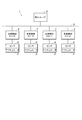
図1は、本発明に係る車両用電子制御システムの構成を表す図である。図1に示すように、本実施形態では、車両用電子制御システム1は、図示しないエンジンを制御するエンジンECUを含む複数の要素制御ユニット2(すなわち前述したエンジンECUやトランスミッションECT(TCU)等の各ECUや、スタビリティコントロールシステムや運転支援システム、ボディスタビライザー等の各システムや装置等)が通信ネットワークNを介して通信可能に接続されて構成されている。なお、他のシステムや装置等が通信ネットワークNに接続されていてもよい。
[Configuration of Electronic Control System for Vehicle]
FIG. 1 is a diagram showing the configuration of a vehicle electronic control system according to the present invention. As shown in FIG. 1, in this embodiment, the vehicle
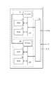
各要素制御ユニット2は、種々の構成を取り得るが、基本的にはマイクロコントローラで構成され、図2に示すように、メインCPU(Central Processing Unit)21やRAM(Random Access Memory)22、ROM(Read Only Memory)23、入出力回路(I/Oポート等ともいう。)24等がバス25に接続されて構成されており、或いは専用装置として構成されているが、いずれもデータ通信機能を有している。
Each
また、各要素制御ユニット2には、自らが制御する制御対象(例えばエンジンECUであればエンジン)に関する情報を計測するための各種のセンサαや、要素制御ユニット2の指示に従って制御対象に必要な動作等を行わせるためのアクチュエータβがそれぞれ接続されている。そして、各要素制御ユニット2は、センサαで計測されたデータ(例えばエンジン回転数やアクセル開度、車速、前後加速度、左右加速度、ヨーレート、操舵角、ブレーキ圧等)を通信ネットワークNに出力する。
In addition, each
また、各要素制御ユニット2はそれぞれ、データに基づいて制御パラメータpを算出するための多次元の制御マップや演算式等を有している。そして、要素制御ユニット2のメインCPU21は、当該要素制御ユニット2のセンサαでデータを計測したり通信ネットワークNを介してデータを受信すると、ROM23に保存されている制御マップを参照したりデータを演算式に代入する等して制御パラメータpを算出し、それに基づいてアクチュエータβを駆動させる等して制御対象に対して必要な制御を行うように構成されている。
Each
一方、本実施形態では、要素制御ユニット2は、メインCPU21のほかにサブCPU26を備えている。すなわち、要素制御ユニット2は、サブCPU26やサブのRAM27、ROM28がバス29に接続されたサブの制御部を備えている。サブCPU26は、メインCPU21と接続されている。そして、サブCPU26は、メインCPU21に異常が発生した場合のフェール制御として、メインCPU21に代わって要素制御ユニット2のアクチュエータβを動作させるための予め設定された制御を行うように構成されている。
On the other hand, in the present embodiment, the
また、サブCPU26は、入出力回路24と接続されており、独自にアクチュエータβを駆動させることが可能であるが、本実施形態では、サブCPU26のROM28は、メインCPU21のROM23よりもメモリ容量が小さく、制御マップ等は保存されていない。そのため、サブCPU26自体では、制御マップを参照してデータから制御パラメータpを算出する等の高度な演算処理を行うことができない。
The
そのため、サブCPU26は、フェール制御における予め設定された制御として、後述する独立ユニット3からアクチュエータβを動作させるために必要な制御パラメータpが送信されてくると、それに基づいてアクチュエータβの動作を制御するようになっている。なお、この点については後で詳しく説明する。また、要素制御ユニット2にサブCPU26が設けられていない場合についても後で説明する。
Therefore, when the control parameter p necessary for operating the actuator β is transmitted from the
一方、車両用電子制御システム1には、独立ユニット3が設けられており、本実施形態では、独立ユニット3は、通信ネットワークNに接続されている。また、本実施形態では、独立ユニット3はマイクロコントローラで構成されており、図示を省略するが、CPUやRAM、ROM、入出力回路等がバスに接続されて構成されている。なお、独立ユニット3にサブCPU等を設ける必要はない。
On the other hand, the vehicle
そして、独立ユニット3は、エンジンやトランスミッション等といった特定の制御対象を持たないようになっている。なお、図1では、独立ユニット3にセンサやアクチュエータが接続されていない場合が示されているが、少なくとも何らかのセンサは接続されていてもよい。
The
そして、車両用電子制御システム1では、通信ネットワークNを介して独立ユニット3と各要素制御ユニット2との間で通信を行うことができるように構成されている。なお、独立ユニット3−要素制御ユニット2間の通信や要素制御ユニット2同士の通信は、例えばCANやCANFD(CAN with Flexible Data rate)、Ethernet(登録商標)等のプロトコルに基づいて行うように構成することが可能であるが、本発明は特定のプロトコルを用いる場合に限定されず、どのようなプロトコルに基づいて通信が行われる場合にも適用される。
The vehicle
また、独立ユニット3は、通信ネットワークNを介して、要素制御ユニット2のセンサαで計測されたデータ(前述したエンジン回転数等)を受信することができるようになっている。また、独立ユニット3のROMには、各要素制御ユニット2のROM23に保存されている制御マップや演算式等の全て、或いは車両を走行させるために必要な制御パラメータpの算出を行うための制御マップや演算式等が保存されており、独立ユニット3は、各要素制御ユニット2のメインCPU21が行う制御パラメータpの算出処理と同様の処理を行って、少なくとも車両を走行させるために必要な制御パラメータpを算出することができるようになっている。
The
そして、独立ユニット3は、ある要素制御ユニット2に異常が発生した場合に、当該要素制御ユニット2の処理の少なくとも一部を行うことにより当該要素制御ユニット2の制御対象であるアクチュエータβの動作を制御するようになっている。この点について説明する前に、独立ユニット3が、ある要素制御ユニット2に異常が発生したことを認識する方法について、いくつかの例を挙げて説明する。
Then, when an abnormality occurs in a certain
1つの方法としては、要素制御ユニット2のサブCPU26が、当該要素制御ユニット2のメインCPU21の動作等を監視し、メインCPU21に異常が発生したことを検知した場合に、独立ユニット3に当該要素制御ユニット2のメインCPU21に異常が発生したことを報知するように構成することが可能である。
As one method, when the
また、別の方法としては、独立ユニット3が、例えば各要素制御ユニット2から通信ネットワークNに出力されるデータを監視し、すなわちデータが出力されているかや、出力されたデータが異常でないか等を監視することで、要素制御ユニット2による要素制御が正常に行われていないと判断した場合に、当該要素制御ユニット2に異常が発生したと判断するように構成することも可能である。
As another method, the
さらに、別の方法としては、各要素制御ユニット2が互いに他の要素制御ユニット2から通信ネットワークNに出力されるデータを監視し(すなわちデータが出力されているかや出力されたデータが異常でないか等を監視し)、他の要素制御ユニット2が異常であると判断した場合に、当該他の要素制御ユニット2が異常である旨を独立ユニット3に通知するように構成し、独立ユニット3は、ある要素制御ユニット2から他の要素制御ユニット2が異常である旨の通知を受けた場合に、当該他の要素制御ユニット2に異常が発生したと判断するように構成することも可能である。
Furthermore, as another method, each
上記のように構成することで、独立ユニット3は、ある要素制御ユニット2に異常が発生した場合に、当該要素制御ユニット2に異常が発生したことを的確に認識することが可能となる。なお、上記のいずれか1つの方法を採用することも可能であるが、要素制御ユニット2の異常を的確に検知するために、上記の各方法による検知を同時並行で行い、いずれかの方法で要素制御ユニット2の異常が検知された場合に、独立ユニット3が、当該要素制御ユニット2に異常が発生したと判断するように構成すればより確実に要素制御ユニット2の異常を検知することができる。
By configuring as described above, the
一方、独立ユニット3は、上記のようにしてある要素制御ユニット2に異常が発生したことを認識すると、当該要素制御ユニット2の処理の少なくとも一部を行うことにより当該要素制御ユニット2の制御対象であるアクチュエータβの動作を制御するようになっている。以下、この点について具体的に説明する。
On the other hand, when the
本実施形態では、独立ユニット3は、要素制御ユニット2のメインCPU21に異常が発生すると、メインCPU21に代わってアクチュエータβを動作させるために必要な制御パラメータpを演算して当該要素制御ユニット2のサブCPU26に送信して、当該サブCPU26にアクチュエータβを動作させるフェール制御を行わせることで、当該要素制御ユニット2のメインCPU21に代わって独立ユニット3がアクチュエータβの動作を制御するようになっている。
In the present embodiment, when an abnormality occurs in the
[作用]
次に、本実施形態に係る車両用電子制御システム1の作用について説明する。
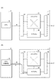
独立ユニット3のCPU31は、図3(A)に示すように、各要素制御ユニット2のうちのある要素制御ユニット2のメインCPU21が故障する等してメインCPU21に異常が発生したことを認識すると、通信ネットワークNからエンジン回転数等の必要なデータを受信し、自らのROMに保存されている、当該要素制御ユニット2で用いられる制御マップや演算式等と同じ制御マップや演算式等に基づいて、図3(B)に示すように当該要素制御ユニット2のアクチュエータβを動作させるために必要な制御パラメータpを代理演算する。そして、演算した制御パラメータpを当該要素制御ユニット2のサブCPU26に送信する。
[Action]
Next, the operation of the vehicle
When the
そして、要素制御ユニット2のサブCPU26は、独立ユニット3から送信された制御パラメータpを受信すると、前述したフェール制御を行い、受信した制御パラメータpに基づいてアクチュエータβの動作を制御して制御対象を動作させる。なお、図3(A)、(B)では、他の各要素制御ユニット2の記載や、独立ユニット3や要素制御ユニット2のRAMやROM、センサα等の記載が省略されている。
When the
この場合、独立ユニット3からは、車両を走行させるために必要な制御パラメータpが送信されるため、要素制御ユニット2のサブCPU26は、例えばSI−DRIVE(登録商標)のようにエンジンの出力特性を通常の出力特性から変えるような付加価値のある制御を行うことはできないとしても、少なくともアクチュエータβが動かなくなったり異常な動作をすることはなくアクチュエータβを適切に動作させることが可能となり、制御対象に最低限の動作を行わせて車両を確実に走行させるようにすることが可能となる。
In this case, since the control parameter p necessary for driving the vehicle is transmitted from the
[効果]
以上のように、本実施形態に係る車両用電子制御システム1によれば、ある要素制御ユニット2に異常が発生した場合には、独立ユニット3が代理で必要な演算を行って必要な制御パラメータpを算出して当該要素制御ユニット2のサブCPU26に送信し、サブCPU26は、独立ユニット3から受信した制御パラメータpに基づいてアクチュエータβの動作を制御する。
[effect]
As described above, according to the vehicle
本実施形態に係る車両用電子制御システム1では、このようにして、異常が発生した要素制御ユニット2のメインCPU21に代わって独立ユニット3が必要な制御パラメータpを代理演算して、当該要素制御ユニット2の処理の少なくとも一部を行うことによりアクチュエータβの動作を制御することで、当該要素制御ユニット2の制御対象を適切に動作させることが可能となり、要素制御ユニット2に異常が発生した場合でも車両を確実に走行させることが可能となる。
In the vehicle
そのため、車両用電子制御システム1内のある要素制御ユニット2に異常が発生した場合でも、車両が走行可能な状態を維持することができるため、車両を走行させてディーラ等に運び込んで、異常が生じた要素制御ユニット2を的確に修理したり交換したりすることが可能となる。また、故障した車両が動かなくなってレッカー移動等が必要になる事態が生じることを的確に回避することが可能となる。
Therefore, even when an abnormality occurs in an
なお、異常が発生した要素制御ユニット2が、エンジンECUやトランスミッションECU(TCU)等のように車両の走行に直接影響する要素制御ユニット2では場合には、上記のように独立ユニット3で制御パラメータpの代理演算を行う対象の要素制御ユニット2に含まれる。しかし、異常が発生した要素制御ユニット2が、オーディオやカーナビ用のCPU等である場合には、車両の走行に直接影響を与えるものではない。そのため、これらの要素制御ユニット2を、独立ユニット3で制御パラメータpの代理演算を行う対象の要素制御ユニット2に含める必要はない。
In the case where the
また、異常が発生した要素制御ユニット2が、スタビリティコントロールシステムや運転支援システム等を担当する要素制御ユニットである場合、それらに異常が発生すると車両の走行が異常になり運転者や乗員に危険が及ぶ可能性がある場合がある。そのため、そのような場合には、これらの要素制御ユニット2を、独立ユニット3で制御パラメータpの代理演算を行う対象の要素制御ユニット2に含めることが可能である。
In addition, when the
[変形例]
ところで、各要素制御ユニット2にサブCPU26が設けられていない場合、独立ユニット3と、所定の要素制御ユニット2(すなわち異常が発生した場合に独立ユニット3が制御パラメータpを代理演算する必要がある要素制御ユニット2)の制御対象であるアクチュエータβとを直接接続しておき、ある要素制御ユニット2に異常が発生した場合に、独立ユニット3が、当該要素制御ユニット2の処理の少なくとも一部を行うことによりアクチュエータβの動作を直接制御するように構成することも可能である。
[Modification]
By the way, when the
しかし、上記の構成を実現するためには、独立ユニット3と各要素制御ユニット2の各アクチュエータβとが接続されていなければならないが、各要素制御ユニット2が車両内に点在するように設けられている現状では必ずしも実現することは容易ではない。しかし、例えば将来的に、各要素制御ユニット2が1つのユニットとして構成される場合には、独立ユニット3もそのユニット内に設けることで実現することが可能である。
However, in order to realize the above configuration, the
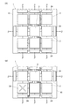
すなわち、この独立ユニット3や各要素制御ユニット2を1つにまとめたユニットをユニット10とする時、例えば図4(A)に示すように、ユニット10内に、独立ユニット3と各要素制御ユニット2を設け、独立ユニット3と各要素制御ユニット2の入出力回路24とをそれぞれ接続しておく。なお、独立ユニット3が独自に入出力回路を有しており、それと各アクチュエータβとを接続するように構成してもよい。また、図4(A)、(B)ではRAMやROM、センサα等の記載が省略されている。
That is, when the
そして、各要素制御ユニット2が正常に機能している状態では、独立ユニット3は、各要素制御ユニット2に異常が発生していないかどうかを監視する(なお、要素制御ユニット2が他の要素制御ユニット2に異常が発生した場合に当該他の要素制御ユニット2が異常である旨を独立ユニット3に通知する場合を含む。)。
Then, in a state where each
そして、図4(B)に示すようにある要素制御ユニット2Aに異常が発生した場合は、独立ユニット3は、当該要素制御ユニット2Aに代わってデータに基づいて制御パラメータpを算出し、それを当該要素制御ユニット2Aの入出力回路24に送信することで、独立ユニット3がアクチュエータβを直接制御するように構成することができる。
When an abnormality occurs in an
このように構成すれば、各要素制御ユニット2がサブCPUを備えていない場合でも、独立ユニット3が、異常を生じた要素制御ユニット2の処理の少なくとも一部を行うことによってアクチュエータβの動作を適切に制御することが可能となり、上記の実施形態と同様の有益な効果を発揮させることが可能となる。
With this configuration, even when each
なお、本発明が上記の実施形態や変形例に限定されず、本発明の趣旨を逸脱しない限り、適宜変更可能であることは言うまでもない。 Needless to say, the present invention is not limited to the above-described embodiments and modifications, and can be appropriately changed without departing from the gist of the present invention.
1 車両用電子制御システム
2 要素制御ユニット
3 独立ユニット
21 メインCPU
26 サブCPU
N 通信ネットワーク
p 制御パラメータ
β アクチュエータ
1 Electronic control system for
26 Sub CPU
N Communication network p Control parameter β Actuator
Claims (6)
特定の制御対象を持たない独立ユニットと、
を備え、
前記独立ユニットと前記要素制御ユニットとの間で通信を行うことができるように構成されており、
前記独立ユニットは、前記要素制御ユニットに異常が発生した場合に、前記要素制御ユニットの処理の少なくとも一部を行うことにより前記アクチュエータの動作を制御することを特徴とする車両用電子制御システム。 An element control unit that performs predetermined element control by controlling the operation of the actuator;
An independent unit without a specific control target,
With
It is configured to be able to communicate between the independent unit and the element control unit,
The vehicle independent control system, wherein the independent unit controls the operation of the actuator by performing at least a part of the processing of the element control unit when an abnormality occurs in the element control unit.
前記サブCPUは、前記メインCPUに異常が発生した場合のフェール制御として、前記メインCPUに代わって前記要素制御ユニットの前記アクチュエータを動作させるための予め設定された制御を行うように構成されており、
前記独立ユニットは、前記要素制御ユニットの前記メインCPUに異常が発生した場合に、前記要素制御ユニットの前記メインCPUに代わって前記アクチュエータを動作させるために必要な制御パラメータを演算して前記サブCPUに送信して前記サブCPUに前記アクチュエータを動作させる前記フェール制御を行わせることで、当該要素制御ユニットの前記メインCPUに代わって前記アクチュエータの動作を制御することを特徴とする請求項1または請求項2に記載の車両用電子制御システム。 The element control unit includes a main CPU and a sub CPU,
The sub CPU is configured to perform preset control for operating the actuator of the element control unit in place of the main CPU as fail control when an abnormality occurs in the main CPU. ,
The independent unit calculates a control parameter necessary for operating the actuator in place of the main CPU of the element control unit when an abnormality occurs in the main CPU of the element control unit, and calculates the sub CPU The operation of the actuator is controlled in place of the main CPU of the element control unit by causing the sub CPU to perform the fail control to operate the actuator by transmitting to the sub CPU. Item 3. The vehicle electronic control system according to Item 2.
前記独立ユニットは、前記要素制御ユニットから他の前記要素制御ユニットが異常である旨の通知を受けた場合に、当該他の要素制御ユニットに異常が発生したと判断することを特徴とする請求項1から請求項5のいずれか一項に記載の車両用電子制御システム。 A plurality of the element control units are provided,
The independent unit determines that an abnormality has occurred in the other element control unit when receiving a notification from the element control unit that the other element control unit is abnormal. The vehicle electronic control system according to any one of claims 1 to 5.
Priority Applications (1)
| Application Number | Priority Date | Filing Date | Title |
|---|---|---|---|
| JP2016187689A JP6761714B2 (en) | 2016-09-27 | 2016-09-27 | Electronic control system for vehicles |
Applications Claiming Priority (1)
| Application Number | Priority Date | Filing Date | Title |
|---|---|---|---|
| JP2016187689A JP6761714B2 (en) | 2016-09-27 | 2016-09-27 | Electronic control system for vehicles |
Publications (2)
| Publication Number | Publication Date |
|---|---|
| JP2018052182A true JP2018052182A (en) | 2018-04-05 |
| JP6761714B2 JP6761714B2 (en) | 2020-09-30 |
Family
ID=61834990
Family Applications (1)
| Application Number | Title | Priority Date | Filing Date |
|---|---|---|---|
| JP2016187689A Active JP6761714B2 (en) | 2016-09-27 | 2016-09-27 | Electronic control system for vehicles |
Country Status (1)
| Country | Link |
|---|---|
| JP (1) | JP6761714B2 (en) |
Citations (8)
| Publication number | Priority date | Publication date | Assignee | Title |
|---|---|---|---|---|
| JP2004318498A (en) * | 2003-04-16 | 2004-11-11 | Toyota Central Res & Dev Lab Inc | Fail safe device |
| JP2009166549A (en) * | 2008-01-11 | 2009-07-30 | Denso Corp | Electronic control device for vehicle |
| JP2010285001A (en) * | 2009-06-09 | 2010-12-24 | Toyota Motor Corp | Electronic control system, function substitution method |
| JP2013084121A (en) * | 2011-10-11 | 2013-05-09 | Hitachi Ltd | Multiple system control device |
| US20140108896A1 (en) * | 2011-06-07 | 2014-04-17 | Daesung Electric Co., Ltd. | Error detecting device and method of a dual controller system |
| JP2014121897A (en) * | 2012-12-20 | 2014-07-03 | Yuhshin Co Ltd | Electric steering lock device |
| JP2014143490A (en) * | 2013-01-22 | 2014-08-07 | Denso Corp | Load Drive circuit |
| JP2015081013A (en) * | 2013-10-23 | 2015-04-27 | 三菱電機株式会社 | Electric power steering controller |
-
2016
- 2016-09-27 JP JP2016187689A patent/JP6761714B2/en active Active
Patent Citations (8)
| Publication number | Priority date | Publication date | Assignee | Title |
|---|---|---|---|---|
| JP2004318498A (en) * | 2003-04-16 | 2004-11-11 | Toyota Central Res & Dev Lab Inc | Fail safe device |
| JP2009166549A (en) * | 2008-01-11 | 2009-07-30 | Denso Corp | Electronic control device for vehicle |
| JP2010285001A (en) * | 2009-06-09 | 2010-12-24 | Toyota Motor Corp | Electronic control system, function substitution method |
| US20140108896A1 (en) * | 2011-06-07 | 2014-04-17 | Daesung Electric Co., Ltd. | Error detecting device and method of a dual controller system |
| JP2013084121A (en) * | 2011-10-11 | 2013-05-09 | Hitachi Ltd | Multiple system control device |
| JP2014121897A (en) * | 2012-12-20 | 2014-07-03 | Yuhshin Co Ltd | Electric steering lock device |
| JP2014143490A (en) * | 2013-01-22 | 2014-08-07 | Denso Corp | Load Drive circuit |
| JP2015081013A (en) * | 2013-10-23 | 2015-04-27 | 三菱電機株式会社 | Electric power steering controller |
Also Published As
| Publication number | Publication date |
|---|---|
| JP6761714B2 (en) | 2020-09-30 |
Similar Documents
| Publication | Publication Date | Title |
|---|---|---|
| US10501063B2 (en) | Brake-by-wire system | |
| CN101151176B (en) | Calculation of the plausibility of sensor signals in the event of a collision | |
| JP6753388B2 (en) | Automatic driving control device, automatic driving control method for vehicles | |
| KR100767074B1 (en) | Failure sensing device of vehicle control system | |
| JP6220232B2 (en) | Vehicle control device | |
| CN110168506B (en) | Control system for a motor vehicle, motor vehicle, method for controlling a motor vehicle | |
| US10525957B2 (en) | Brake-by-wire system | |
| US10507816B2 (en) | Brake-by-wire system | |
| US20180056961A1 (en) | Brake-by-wire system | |
| US12255757B2 (en) | Relay device system | |
| US11787426B2 (en) | Control system for a motor vehicle having a first control device and a second control device to control first and second functions of the motor vehicle and method for controlling a motor vehicle | |
| JP2008505012A (en) | Redundant data bus system | |
| US11405233B2 (en) | Relay device system | |
| KR20200022674A (en) | Apparatus for controlling fail-operational of vehicle, and method thereof | |
| EP3838672B1 (en) | Autonomous vehicle and method for controlling it | |
| KR20240021346A (en) | Apparatus for controlling a vehicle and method thereof | |
| WO2019239798A1 (en) | Electronic control device and electronic control system | |
| EP3790233B1 (en) | In-vehicle network system | |
| JP2015067234A (en) | Vehicle control device | |
| US11318953B2 (en) | Fault-tolerant embedded automotive applications through cloud computing | |
| JP7521639B2 (en) | Driving Control System | |
| JP2018052182A (en) | Electronic control system for vehicles | |
| US9187070B2 (en) | System and method for maintaining operational states of vehicle remote actuators during failure conditions | |
| KR20240020953A (en) | Apparatus for controlling a vehicle and method thereof | |
| KR20180107666A (en) | Method for controlling smart cruise control of hybrid electric vehicle |
Legal Events
| Date | Code | Title | Description |
|---|---|---|---|
| A621 | Written request for application examination |
Free format text: JAPANESE INTERMEDIATE CODE: A621 Effective date: 20190617 |
|
| A977 | Report on retrieval |
Free format text: JAPANESE INTERMEDIATE CODE: A971007 Effective date: 20200327 |
|
| A131 | Notification of reasons for refusal |
Free format text: JAPANESE INTERMEDIATE CODE: A131 Effective date: 20200512 |
|
| A521 | Request for written amendment filed |
Free format text: JAPANESE INTERMEDIATE CODE: A523 Effective date: 20200619 |
|
| TRDD | Decision of grant or rejection written | ||
| A01 | Written decision to grant a patent or to grant a registration (utility model) |
Free format text: JAPANESE INTERMEDIATE CODE: A01 Effective date: 20200811 |
|
| A61 | First payment of annual fees (during grant procedure) |
Free format text: JAPANESE INTERMEDIATE CODE: A61 Effective date: 20200907 |
|
| R150 | Certificate of patent or registration of utility model |
Ref document number: 6761714 Country of ref document: JP Free format text: JAPANESE INTERMEDIATE CODE: R150 |
|
| R250 | Receipt of annual fees |
Free format text: JAPANESE INTERMEDIATE CODE: R250 |
|
| R250 | Receipt of annual fees |
Free format text: JAPANESE INTERMEDIATE CODE: R250 |
|
| R250 | Receipt of annual fees |
Free format text: JAPANESE INTERMEDIATE CODE: R250 |