JP2018037726A - Conversion rule deriving device, communication device, and conversion rule deriving and providing method - Google Patents
Conversion rule deriving device, communication device, and conversion rule deriving and providing method Download PDFInfo
- Publication number
- JP2018037726A JP2018037726A JP2016166884A JP2016166884A JP2018037726A JP 2018037726 A JP2018037726 A JP 2018037726A JP 2016166884 A JP2016166884 A JP 2016166884A JP 2016166884 A JP2016166884 A JP 2016166884A JP 2018037726 A JP2018037726 A JP 2018037726A
- Authority
- JP
- Japan
- Prior art keywords
- signal
- conversion rule
- bit string
- digital modulation
- value
- Prior art date
- Legal status (The legal status is an assumption and is not a legal conclusion. Google has not performed a legal analysis and makes no representation as to the accuracy of the status listed.)
- Granted
Links
Images
Landscapes
- Digital Transmission Methods That Use Modulated Carrier Waves (AREA)
Abstract
【課題】様々な変調方式に対応でき、かつ、マッピングに必要な情報量を削減することのできる変換規則導出装置、通信装置、変換規則導出提供方法を提供する。【解決手段】制御部12が、記憶部11に記憶されている値に基づいて、信号空間ダイヤグラムにおいて、第1のデジタル変調方式における各信号点のうち、第2のデジタル変調方式における信号点と重複する信号点に対応するビット列と、第2のデジタル変調方式において信号点と重複する信号点に対応するビット列とを相互に変換するための変換規則を導出する。提供部13が、制御部12が導出した変換規則を通信装置に提供する。【選択図】 図20PROBLEM TO BE SOLVED: To provide a conversion rule derivation device, a communication device, and a conversion rule derivation providing method capable of supporting various modulation methods and reducing the amount of information required for mapping. SOLUTION: A control unit 12 sets a signal point in a second digital modulation method among each signal point in the first digital modulation method in a signal space diagram based on a value stored in the storage unit 11. A conversion rule for converting the bit string corresponding to the overlapping signal point and the bit string corresponding to the signal point and the overlapping signal point in the second digital modulation method with each other is derived. The providing unit 13 provides the communication device with the conversion rule derived by the control unit 12. [Selection diagram] FIG. 20
Description
本発明は、変換規則導出装置、通信装置、変換規則導出提供方法に関する。 The present invention relates to a conversion rule derivation device, a communication device, and a conversion rule derivation providing method.
デジタル変調を行う通信装置は、複数の多値度の変調方式に対応していることがある。例えば、無線LAN(Local Area Network)の規格であるIEEE(Institute of Electrical and Electronics Engineers)802.11acにおいて、通信装置は、BPSK(Binary Phase Shift Keying)、QPSK(Quadrature Phase Shift Keying)、16QAM(Quadrature Amplitude Modulation)、64QAMおよび256QAMによる変調に対応する必要がある。 A communication device that performs digital modulation may support a plurality of multilevel modulation schemes. For example, in IEEE (Institute of Electrical and Electronics Engineers) 802.11ac, which is a standard for wireless LAN (Local Area Network), the communication device is BPSK (Binary Phase Shift Key BP). (Amplitude Modulation), 64QAM and 256QAM modulation must be supported.
また、ケーブルテレビジョン回線を利用して通信する通信装置が、複数の多値度の変調方式に対応している場合がある。例えば、ケーブルテレビジョン回線を利用した通信方式の規格であるDOCSIS(Data Over Cable Service Interface Specifications)3.1において、通信装置は、下り通信で1024QAM、2048QAMおよび4096QAM、上り通信で128QAM、256QAM、512QAM、1024QAM、2048QAMおよび4096QAMによる変調に対応する必要がある。 In addition, a communication device that communicates using a cable television line may support a plurality of multilevel modulation schemes. For example, in DOCSIS (Data Over Cable Service Specifications) 3.1, which is a standard of a communication system using a cable television line, the communication device is 1024QAM, 2048QAM and 4096QAM for downlink communication, 128QAM, 256QAM, 512QAM for uplink communication. It is necessary to support modulation by 1024QAM, 2048QAM and 4096QAM.
QAMは、I(In−phase)成分とQ(Quadrature)成分とからなる2次元座標系において対応する信号点に、2進数のデータをマッピングする変調方式である。例えば、256QAMでは、2次元座標系(I軸と、Q軸とからなる2次元複素平面座標系)における256個の信号点のいずれかに、8ビットのデータがマッピングされる。 QAM is a modulation scheme that maps binary data to corresponding signal points in a two-dimensional coordinate system composed of an I (In-phase) component and a Q (Quadrature) component. For example, in 256QAM, 8-bit data is mapped to any of 256 signal points in a two-dimensional coordinate system (a two-dimensional complex plane coordinate system including an I axis and a Q axis).
特許文献1に記載された発明では、入力されたビット列の所定の位置にビットが追加され、さらに、入力されたビット列の一部または全部のビットの値が反転されることにより、ビット列の変換が行われる。そして、特許文献1に記載された発明では、変調方式に対応する信号空間ダイヤグラム上のいずれかのシンボルに、変換されたビット列をマッピングするマッピング処理が行われる。
In the invention described in
特許文献1に記載された発明では、ビットの追加操作およびビットの反転操作のみを行い、BPSK、QPSK、16QAM、32QAM、64QAMおよび256QAMに適用可能であるが、128QAM等の特定の変調方式にも適用可能であることが好ましい。
In the invention described in
本発明は、上記課題に鑑み、様々な変調方式に対応でき、かつ、マッピングに必要な情報量を削減することのできる変換規則導出装置、通信装置、変換規則導出提供方法を提供することを目的とする。 An object of the present invention is to provide a conversion rule deriving device, a communication device, and a conversion rule deriving and providing method that can cope with various modulation schemes and reduce the amount of information necessary for mapping. And
本発明の変換規則導出装置は、通信装置が対応可能な複数のデジタル変調方式において、各デジタル変調方式の信号空間ダイヤグラムにおける信号点に応じた値が前記信号点に対応するビット列に対応付けられて記憶されている記憶手段と、前記記憶手段に記憶されている前記値に基づいて、前記信号空間ダイヤグラムにおいて、第1のデジタル変調方式における各信号点のうち、第2のデジタル変調方式における信号点と重複する信号点に対応するビット列と、前記第2のデジタル変調方式において前記信号点と重複する信号点に対応するビット列とを相互に変換するための変換規則を導出する制御手段と、前記制御手段が導出した前記変換規則を前記通信装置に提供する提供手段と、を備える。 In the conversion rule deriving device of the present invention, in a plurality of digital modulation schemes that can be supported by a communication device, a value corresponding to a signal point in a signal space diagram of each digital modulation scheme is associated with a bit string corresponding to the signal point. Based on the stored storage means and the value stored in the storage means, in the signal space diagram, out of the signal points in the first digital modulation system, the signal points in the second digital modulation system Control means for deriving a conversion rule for mutually converting a bit string corresponding to a signal point overlapping with the signal point and a bit string corresponding to the signal point overlapping with the signal point in the second digital modulation scheme; Providing means for providing the communication device with the conversion rule derived by the means.
本発明の通信装置は、信号空間ダイヤグラムにおける信号配置に基づき、第1のデジタル変調方式の各信号点の値に応じたビット列と、前記各信号点に重複する、第2のデジタル変調方式における各信号点の値に応じたビット列とを相互に変換するための変換規則に基づいて、前記第1のデジタル変調方式に応じた送信用データを前記第2のデジタル変調方式に応じた変換後データに変換するデータ変換手段と、前記変換後データに、前記第2のデジタル変調方式で変調を施して送信信号を生成する変調手段と、前記送信信号を送信する送信手段と、を備える。 The communication device of the present invention is based on the signal arrangement in the signal space diagram, and a bit string corresponding to the value of each signal point of the first digital modulation method and each of the second digital modulation methods overlapping each signal point. Based on the conversion rule for mutually converting the bit string corresponding to the value of the signal point, the transmission data according to the first digital modulation method is converted into the converted data according to the second digital modulation method. Data conversion means for converting, modulation means for generating a transmission signal by modulating the converted data by the second digital modulation method, and transmission means for transmitting the transmission signal.
本発明の他の態様の通信装置は、受信した送信信号を前記送信信号に応じた復調方式で変換後データに復調する復調手段と、信号空間ダイヤグラムにおける信号配置に基づき、第1のデジタル変調方式の各信号点の値に応じたビット列と、前記各信号点に重複する、第2のデジタル変調方式における各信号点の値に応じたビット列とを相互に変換するための変換規則に基づいて、前記第2のデジタル変調方式に応じた変換後データを前記第1のデジタル変調方式に応じた送信用データに変換するデータ変換手段と、を備える。 A communication apparatus according to another aspect of the present invention includes a demodulating unit that demodulates a received transmission signal into post-conversion data by a demodulation method according to the transmission signal, and a first digital modulation method based on a signal arrangement in a signal space diagram. Based on a conversion rule for mutually converting a bit string corresponding to the value of each signal point and a bit string corresponding to the value of each signal point in the second digital modulation scheme, which overlaps with each signal point, Data conversion means for converting the converted data according to the second digital modulation method into transmission data according to the first digital modulation method.
本発明の変換規則導出提供方法は、通信装置が対応可能な複数のデジタル変調方式において、各デジタル変調方式の信号空間ダイヤグラムにおける信号点に応じた値が前記信号点に対応するビット列に対応付けられて記憶されている記憶手段に記憶されている前記値に基づいて、前記信号空間ダイヤグラムにおいて、第1のデジタル変調方式における各信号点のうち、第2のデジタル変調方式における信号点と重複する信号点に対応するビット列と、前記第2のデジタル変調方式において前記信号点と重複する信号点に対応するビット列とを相互に変換するための変換規則を導出し、導出した前記変換規則を前記通信装置に提供する。 In the conversion rule derivation and provision method of the present invention, in a plurality of digital modulation schemes that can be supported by a communication apparatus, a value corresponding to a signal point in a signal space diagram of each digital modulation scheme is associated with a bit string corresponding to the signal point. Based on the value stored in the storage means stored in the signal, in the signal space diagram, among the signal points in the first digital modulation system, signals that overlap with the signal points in the second digital modulation system A conversion rule for mutually converting a bit string corresponding to a point and a bit string corresponding to a signal point overlapping with the signal point in the second digital modulation method is derived, and the derived conversion rule is used as the communication device. To provide.
幅広い変調方式に対応でき、かつ、マッピングに必要な情報量を削減できる。 A wide range of modulation methods can be supported, and the amount of information required for mapping can be reduced.
<第1の実施形態>
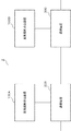
図1は、第1の実施形態の通信システム1の構成例を示すブロック図である。通信システム1は、変換規則導出装置100と、送信側の通信装置200と、受信側の通信装置300とを含む。変換規則導出装置100と、通信装置200と、通信装置300とは、互いに通信可能に接続され、例えば、無線伝送路または有線伝送路を介して互いの間で通信が行われる。
<First Embodiment>
FIG. 1 is a block diagram illustrating a configuration example of a
図2は、変換規則導出装置100の構成例を示すブロック図である。図2に示すように、変換規則導出装置100は、制御部110と、記憶部120と、出力部130とを含む。
FIG. 2 is a block diagram illustrating a configuration example of the conversion
制御部110は、記憶部120に格納されている所定の変調方式に応じた信号空間ダイヤグラム上の各信号点の位置のI成分の値およびQ成分の値に基づき、所定の変調方式に応じたビット列を、別の所定の変調方式に応じたビット列に変換するための変換規則を導出する。
Based on the value of the I component and the value of the Q component at the position of each signal point on the signal space diagram corresponding to the predetermined modulation method stored in the
例えば、制御部110は、256QAMのデータに応じたビット列と、128QAMのデータに応じたビット列とを相互に変換するための変換規則を導出する。例えば、制御部110は、128QAMに応じた信号空間ダイヤグラム上の各信号点の位置のI成分の値およびQ成分の値が格納されているメモリアドレスに対応するビット列と、256QAMに応じた信号空間ダイヤグラム上の各信号点の位置のI成分の値およびQ成分の値が格納されているメモリアドレスに対応するビット列とを比較し、変換規則を導出する。制御部110による変換規則の導出処理の詳細は、後述する。
For example, the
また、例えば、制御部110は、プログラム制御に従って処理を実行するCPU(Central Processing Unit)や複数の回路等によって実現される。
Further, for example, the
記憶部120には、所定の変調方式に応じたデータ(ビット列)をメモリアドレスとした、所定の変調方式に応じた各信号点の位置のI成分の値およびQ成分の値が格納されている。
The
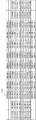
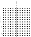
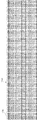
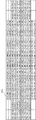
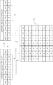
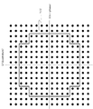
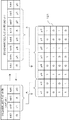
図3は、128QAMに応じた信号空間ダイヤグラムの一例を示す図である。図4は、128QAMの各信号点に応じたビット列の情報の一例を示す図である。図5は、256QAMに応じた信号空間ダイヤグラムの一例を示す図である。図6は、256QAMの各信号点に応じたビット列の情報の一例を示す図である。図7は、256QAMに応じた信号点に対応するビット列の情報のうち、128QAMに応じた信号点に対応するビット列と重複するビット列の情報を示す図である。 FIG. 3 is a diagram illustrating an example of a signal space diagram according to 128QAM. FIG. 4 is a diagram illustrating an example of bit string information corresponding to each 128QAM signal point. FIG. 5 is a diagram illustrating an example of a signal space diagram according to 256QAM. FIG. 6 is a diagram illustrating an example of bit string information corresponding to each signal point of 256QAM. FIG. 7 is a diagram illustrating bit string information overlapping with a bit string corresponding to a signal point corresponding to 128 QAM, out of bit string information corresponding to a signal point corresponding to 256 QAM.
例えば、記憶部120には、図3に示すような128QAMに応じた信号空間ダイヤグラム上の各信号点の位置のI成分の値およびQ成分の値が、図4に示すような128QAMの各信号点に応じたビット列のメモリアドレスに格納されている。また、例えば、記憶部120には、図5に示すような256QAMに応じた信号空間ダイヤグラム上の各信号点のうち、128QAMの各信号点に応じた位置のI成分の値およびQ成分の値が、図7に示すような256QAMの各信号点に応じたビット列のメモリアドレスに格納されている。
For example, the
例えば、図3に示されている信号点140は、図4に示す7ビットのビット列150(“0000001”)に対応しており、ビット列150は、信号点140にマッピングされることが示され、記憶部120のメモリアドレス“0000001”に、信号点140の位置のI成分の値およびQ成分の値が格納されている。また、図5に示されている信号点180は、図6および図7に示す8ビットのビット列190(“01100011”)に対応しており、ビット列190は、信号点180にマッピングされることが示され、記憶部120のメモリアドレス“01100011”に信号点180の位置のI成分の値およびQ成分の値が格納されている。
For example, the
なお、記憶部120において、例えば、128QAMに応じた信号空間ダイヤグラム上の各信号点の位置のI成分の値およびQ成分の値が格納されている128QAMの各信号点に応じたビット列のメモリアドレスと、256QAMに応じた信号空間ダイヤグラム上の各信号点のうち、128QAMの各信号点に応じた位置のI成分の値およびQ成分の値が格納されている256QAMの各信号点に応じたビット列のメモリアドレスとは、互いに重複しないように設定されている。
In the
例えば、128QAMに応じた信号空間ダイヤグラム上の各信号点の位置のI成分の値およびQ成分の値は、記憶部120において、128QAMの各信号点に応じたビット列の先頭に“00”という2ビットを付加したメモリアドレスに格納されている。例えば、図3に示されている信号点140の位置のI成分の値およびQ成分の値は、記憶部120のメモリアドレス“000000001”に格納されている。
For example, the I component value and the Q component value at the position of each signal point on the signal space diagram according to 128QAM are stored in the
また、例えば、256QAMに応じた信号空間ダイヤグラム上の各信号点のうち、128QAMの各信号点に応じた位置のI成分の値およびQ成分の値は、記憶部120において、256QAMの各信号点に応じたビット列の先頭に“1”という1ビットを付加したメモリアドレスに格納されている。例えば、図5に示されている信号点180の位置のI成分の値およびQ成分の値は、記憶部120のメモリアドレス“101100011”に格納されている。なお、先頭に上記1ビットまたは2ビットが付加された場合に、例えば、制御部110は、後述する変換規則を導出する際には、先頭に付加された上記1ビットまたは2ビットを削除する。
Also, for example, among the signal points on the signal space diagram according to 256QAM, the value of the I component and the value of the Q component at the position corresponding to each signal point of 128QAM are stored in the
なお、例えば、記憶部120には、256QAMに応じた信号空間ダイヤグラム上の各信号点のうち、128QAMの各信号点に応じた位置のI成分の値およびQ成分の値のみが格納されていてもよいし、256QAMに応じた信号空間ダイヤグラム上の各信号点に応じた位置のI成分の値およびQ成分の値が全て格納されていてもよい。
For example, the
また、記憶部120には、変数mと、変数nとが格納される。ここで、変数mは、入力された128QAMに応じたデータのビット位置を示す。128QAMに応じたデータは、7ビットであるため、mは0以上6以下の値である。また、変数nは、256QAMに応じたデータのビット位置を示す。256QAMに応じたデータは、8ビットであるため、nは、0以上7以下の値である。
In addition, the
なお、各ビット列において、0ビット目が、LSB(Least Significant Bit:最下位ビット)である。また、128QAMに応じたデータのビット列において、6ビット目(m=6)が、MSB(Most Significant Bit:最上位ビット)であり、256QAMに応じたデータのビット列において、7ビット目(n=7)が、MSBである。 In each bit string, the 0th bit is an LSB (Least Significant Bit). In the bit string of data corresponding to 128QAM, the sixth bit (m = 6) is the MSB (Most Significant Bit), and the seventh bit (n = 7) in the bit string of data corresponding to 256QAM. ) Is the MSB.
また、記憶部120には、制御部110が導出した変換規則の情報が格納される。なお、例えば、記憶部120は、メモリ等によって実現される。
The
出力部130は、制御部110によって導出された変換規則の情報を送信する。例えば、出力部130は、送信機およびアンテナ等によって実現され、通信装置200および通信装置300に、変換規則の情報を送信する。
The
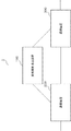
図8は、通信装置200の構成例を示すブロック図である。図8に示すように、通信装置200は、制御部210と、記憶部220と、通信部230とを含む。通信装置200は、例えば、ケーブルテレビジョン回線等を利用して有線通信を行う通信装置や、無線通信を行う基地局やユーザ端末等の通信装置である。
FIG. 8 is a block diagram illustrating a configuration example of the
記憶部220には、所定の変調方式に応じた信号空間ダイヤグラム上の各信号点の位置のI成分の値およびQ成分の値が格納されている。また、記憶部220には、制御部210によって使用される変換規則の情報が格納される。なお、記憶部220は、例えば、メモリやハードディスク等によって実現される。
The
例えば、記憶部220には、図5に示すような256QAMに応じた信号空間ダイヤグラム上の各信号点の位置のI成分の値およびQ成分の値が、図6に示すような256QAMの各信号点に対応するビット列のメモリアドレスに格納されている。例えば、図5において、信号点160は、図6に示す8ビットのビット列170(“00000000”)と対応しており、ビット列170は、信号点160にマッピングされることを示しており、記憶部220のメモリアドレス“00000000”に信号点160のI成分の値およびQ成分の値が格納されている。
For example, the
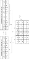
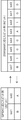
図9は、変換規則の例を示す説明図である。例えば、記憶部220には、図9に示すような、128QAMに応じたデータを、256QAMに応じたデータに変換するための変換規則が格納される。例えば、図9には、256QAMに応じたビットのビット列“D、y3、y2、C、B、y1、y0、A”と、128QAMに応じたビットのビット列 “D、x2、x1、C、B、x0、A”とを相互に変換するための変換規則が示されている。なお、図9では、128QAMに応じたビットのビット列が、実線で示した矢印の方向で、256QAMに応じたビットのビット列に変換される。図9に示す変換規則では、128QAMに応じたビット列および256QAMに応じたビット列に含まれる、A、B、CおよびDに対応する位置のビットの値は、それぞれ同じ値となる。
FIG. 9 is an explanatory diagram illustrating an example of a conversion rule. For example, the
また、128QAMに応じたビット列に含まれるx0、x1およびx2に対応する位置におけるそれぞれのビットの値の組合せに応じて、256QAMに応じたビット列に含まれるy0、y1、y2およびy3に対応する位置におけるそれぞれのビットの値の組合せが決定される。 Further, positions corresponding to y0, y1, y2, and y3 included in the bit string corresponding to 256QAM according to combinations of values of the respective bits at positions corresponding to x0, x1, and x2 included in the bit string corresponding to 128QAM. The combination of the values of each bit in is determined.
x0、x1およびx2に対応する位置のビットの値の組合せと、y0、y1、y2およびy3に対応する位置のビットの値の組合せとの関係が、図9に示す変換規則テーブル121に示されている。例えば、128QAMに応じたビット列に含まれるx0、x1およびx2に対応する位置のビットの値がすべて“0”の場合(図9に示す変換規則テーブル121の2行目の場合)に、256QAMに応じたビット列に含まれるy3、y2、y1およびy0に対応する位置のそれぞれのビットの値が“1”、“1”、“0”および“1”に決定される。 The relationship between the combination of bit values at positions corresponding to x0, x1, and x2 and the combination of bit values at positions corresponding to y0, y1, y2, and y3 is shown in the conversion rule table 121 shown in FIG. ing. For example, when all the bit values at positions corresponding to x0, x1 and x2 included in the bit string corresponding to 128QAM are “0” (in the case of the second row of the conversion rule table 121 shown in FIG. 9), 256QAM The value of each bit at the position corresponding to y3, y2, y1, and y0 included in the corresponding bit string is determined as “1”, “1”, “0”, and “1”.
制御部210は、変調方式を示す制御信号と、記憶部220に格納される変換規則の情報とに基づき、通信部230から入力された入力データ(ビット列)を変換する。
The
また、制御部210は、記憶部220に格納されている所定の変調方式に応じた信号空間ダイヤグラム上の各信号点の位置のI成分の値およびQ成分の値に基づき、入力データを対応する信号点にマッピングし、マッピングした信号点の位置のI成分の値およびQ成分の値を通信部230に入力する。例えば、制御部210は、入力データのビット列に応じた記憶部220のメモリアドレスを参照し、当該参照したメモリアドレスに格納されている信号点の位置のI成分の値およびQ成分の値を取得し、取得した信号点の位置のI成分の値およびQ成分の値を通信部230に入力する。
Further, the
なお、通信装置200は、変調方式を決定する変調方式決定部を含み、制御信号は、変調方式決定部から入力された信号でもよい。また、通信装置200とは別の装置が変調方式を決定し、制御信号は、当該別の装置から送信された信号でもよい。
また、制御部210は、通信部230に、入力データの変調方式を示す情報を入力する。入力データの変調方式を示す情報は、例えば、128QAMに応じた入力データ(ビット列)が256QAMに応じた入力データ(ビット列)に変換された場合に、128QAMであることを示す情報である。また、入力データの変調方式を示す情報は、例えば、256QAMに応じたデータ(ビット列)が入力されたことによって、制御部210において変換処理が行われなかった場合に、256QAMであることを示す情報である。制御部210は、例えば、プログラム制御に従って処理を実行するCPUや複数の回路等によって実現される。
In addition, the
通信部230は、変換規則導出装置100から送信された変換規則の情報を受信し、記憶部220に変換規則の情報を入力する。また、通信部230は、外部機器等から入力された入力データを制御部210に入力する。また、通信部230は、制御部210から入力されたI成分の値およびQ成分の値に基づき、搬送波を変調し、変調後の搬送波を送信する。また、制御部210から、入力データの変調方式を示す情報が入力された場合に、通信部230は、入力データの変調方式を示す情報を含む変調後の搬送波を送信する。例えば、通信部230は、送信機、受信機およびアンテナ等によって実現される。
The
例えば、通信装置200が基地局である場合に、通信部230は、変調後の搬送波を通信端末(ユーザ端末等)に送信する。また、通信装置200が通信端末(ユーザ端末等)である場合に、通信部230は、変調後の搬送波を基地局に送信する。
For example, when the
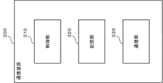
図10は、通信装置300の構成例を示すブロック図である。図10に示すように、通信装置300は、制御部310と、記憶部320と、通信部330とを含む。通信装置300は、例えば、ケーブルテレビジョン回線等を利用して有線通信を行う通信装置や、無線通信を行う基地局やユーザ端末等の通信装置である。
FIG. 10 is a block diagram illustrating a configuration example of the
記憶部320には、所定の変調方式に応じた信号空間ダイヤグラム上の各信号点の位置のI成分の値およびQ成分の値が格納されている。また、記憶部320には、制御部310によって使用される変換規則の情報が格納される。なお、記憶部320は、例えば、メモリやハードディスク等によって実現される。
The
例えば、記憶部320には、図5に示すような256QAMに応じた信号空間ダイヤグラム上の各信号点の位置のI成分の値およびQ成分の値が、図6に示すような256QAMの各信号点に対応するビット列のメモリアドレスに格納されている。例えば、図5において、信号点160は、図6に示す8ビットのビット列170(“00000000”)と対応しており、ビット列170は、信号点160にマッピングされることを示しており、記憶部320のメモリアドレス“00000000”に信号点160のI成分の値およびQ成分の値が格納されている。
For example, in the
また、例えば、記憶部320には、図9に示すような、256QAMに応じたデータを、128QAMに応じたデータに変換するための変換規則が格納される。例えば、図9には、128QAMに応じたビットのビット列“D、x2、x1、C、B、x0、A”と、256QAMに応じたビットのビット列“D、y3、y2、C、B、y1、y0、A”とを相互に変換するための変換規則が示されている。なお、図9では、256QAMに応じたビットのビット列が、破線で示した矢印の方向で、128QAMに応じたビットのビット列に変換される。図9に示す変換規則では、128QAMに応じたビット列および256QAMに応じたビット列に含まれる、A、B、CおよびDに対応する位置のビット値は、それぞれ同じ値となる。
For example, the
また、128QAMに応じたビット列に含まれるx0、x1およびx2に対応する位置におけるそれぞれのビットの値の組合せに応じて、256QAMに応じたビット列に含まれるy0、y1、y2およびy3に対応する位置におけるそれぞれのビットの値の組合せが決定される。 Further, positions corresponding to y0, y1, y2, and y3 included in the bit string corresponding to 256QAM according to combinations of values of the respective bits at positions corresponding to x0, x1, and x2 included in the bit string corresponding to 128QAM. The combination of the values of each bit in is determined.
x0、x1およびx2に対応する位置のビットの値の組合せと、y0、y1、y2およびy3に対応する位置のビットの値の組合せとの関係が、図9に示す変換規則テーブル121に示されている。例えば、256QAMに応じたビット列に含まれるy3、y2、y1およびy0に対応する位置のそれぞれのビットの値が“1”、“1”、“0”および“1”の場合(図9に示す変換規則テーブル121の2行目の場合)に、128QAMに応じたビット列に含まれるx0、x1およびx2に対応する位置のビットの値がすべて“0”に決定される。 The relationship between the combination of bit values at positions corresponding to x0, x1, and x2 and the combination of bit values at positions corresponding to y0, y1, y2, and y3 is shown in the conversion rule table 121 shown in FIG. ing. For example, when the value of each bit in the position corresponding to y3, y2, y1 and y0 included in the bit string according to 256QAM is “1”, “1”, “0” and “1” (shown in FIG. 9) In the case of the second row of the conversion rule table 121), the values of the bits at the positions corresponding to x0, x1 and x2 included in the bit string corresponding to 128QAM are all determined to be “0”.
通信部330は、変換規則導出装置100から送信された変換規則の情報を受信し、記憶部320に変換規則の情報を入力する。また、通信部330は、通信装置200から送信された信号を受信し、制御部310に当該信号を入力する。また、通信部330は、制御部310から入力された通信装置200の入力データを、例えば、セットトップボックス等の外部機器に出力する。例えば、通信部330は、送信機、受信機およびアンテナ等によって実現される。
The
例えば、通信装置300が基地局である場合に、通信部330は、変調後の搬送波を通信端末(ユーザ端末等)から受信する。また、通信装置300が通信端末(ユーザ端末等)である場合に、通信部330は、変調後の搬送波を基地局から受信する。
For example, when the
通信部330は、受信した信号に、入力データの変調方式を示す情報が含まれているか否かを判断する。そして、通信部330は、入力データの変調方式を示す情報が含まれていると判断した場合に、制御部310に、変調方式を示す制御信号を入力する。変調方式を示す制御信号は、例えば、通信装置200において、128QAMに応じた入力データ(ビット列)が256QAMに応じた入力データ(ビット列)に変換された場合に、128QAMであることを示す制御信号である。また、変調方式を示す制御信号は、例えば、通信装置200において、128QAMに応じた入力データ(ビット列)が256QAMに応じた入力データ(ビット列)に変換されていない場合に、256QAMであることを示す制御信号である。
The
なお、例えば、通信部330が、通信装置300とは別の装置から変調方式を示す信号を受信し、当該変調方式を示す信号に基づき、制御部310に、変調方式を示す制御信号を入力してもよい。例えば、変調方式を示す信号は、128QAMであることを示す信号、または256QAMであることを示す信号である。例えば、通信部330は、128QAMであることを示す信号を受信した場合に、制御部310に、128QAMであることを示す制御信号を入力する。なお、通信装置300とは別の装置によって送信された変調方式を示す制御信号を受信し、受信した制御信号を制御部310に入力する変調方式決定部を通信装置300が備えるように構成されていてもよい。
For example, the
制御部310は、通信部330が受信した変調された搬送波を復調する。例えば、制御部310は、通信部330が信号を受信した場合、受信した信号のI成分の値およびQ成分の値を取得する。そして、例えば、制御部310は、受信した信号に施された変調に対応した信号点の位置のI成分の値およびQ成分の値を取得し、このI成分の値およびQ成分の値が格納されている記憶部320のメモリアドレスを参照し、当該メモリアドレスの値を受信したデータ(ビット列)として取得する。
The
制御部310は、変調方式を示す制御信号が入力された場合に、記憶部320に格納される変換規則の情報に基づき、取得した受信データ(ビット列)を通信装置200の入力データに変換する。例えば、制御部310は、制御信号によって、128QAMであることが示されている場合に、記憶部320に格納される図9に示す変換規則に基づき、256QAMに応じた受信データ(ビット列)を変換し、128QAMに応じた通信装置200の入力データ(ビット列)を取得する。そして、制御部310は、取得した通信装置200の入力データを通信部330に入力する。なお、制御部310は、例えば、プログラム制御に従って処理を実行するCPUや複数の回路等によって実現される。
When the control signal indicating the modulation method is input, the
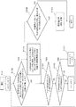
図11は、変換規則導出装置100による変換規則導出の処理を示すフローチャートである。図11に示すフローチャートでは、変換規則導出装置100は、128QAMに応じたデータのビット列(7ビット)と、256QAMに応じたデータのビット列(8ビット)とを相互に変換するための変換規則を導出する。
FIG. 11 is a flowchart showing conversion rule derivation processing by the conversion
制御部110は、変数mおよび変数nの値を0に設定し、記憶部120に変数mおよび変数nの値を格納する(ステップS101)。
制御部110は、128QAMに応じた信号空間ダイヤグラム上の各信号点の位置のI成分の値およびQ成分の値が格納されている記憶部120のメモリアドレスに対応するビット列と、256QAMに応じた信号空間ダイヤグラム上の各信号点の位置のI成分の値およびQ成分の値が格納されている記憶部120のメモリアドレスに対応するビット列とを比較する。そして、制御部110は、各信号点において、128QAMに応じたビット列のmビット目の値と、256QAMに応じたビット列のnビット目の値とが等しいか否かを判断する(ステップS102)。
The
例えば、制御部110は、ステップS102の処理で、m=0かつn=0の場合、図3に示す信号点140に対応する、図4に示すビット列150(“0000001”)の0ビット目の値と、図5に示す信号点180に対応する、図7に示すビット列190(“01100011”)の0ビット目の値とが等しいか否かを判断する。本例では、制御部110は、信号点140に対応するビット列150の0ビット目の値と、信号点140と同じ信号点の位置となる信号点180に対応するビット列190の0ビット目の値とが等しいと判断する。
For example, when m = 0 and n = 0 in the process of step S102, the
制御部110は、128QAMに応じたビット列のmビット目の値と256QAMに応じたビット列のnビット目の値とが等しいと判断した場合に(ステップS102のYES)、128QAMに応じたビット列のmビット目の値を256QAMに応じたビット列のnビット目に配置する変換規則を導出する(ステップS103)。そして、制御部110は、ステップS104の処理に移行する。
When the
制御部110は、128QAMに応じたビット列のmビット目の値と256QAMに応じたビット列のnビット目の値とが等しくないと判断した場合に(ステップS102のNO)、ステップS104の処理に移行する。
When the
制御部110は、ステップS104の処理で、mの値が、128QAMに応じたビット列のMSBであるか否かを判断する(ステップS104)。
The
制御部110は、mの値が、128QAMに応じたビット列のMSBでないと判断した場合に(ステップS104のNO)、nの値が256QAMに応じたビット列のMSBであるか否かを判断する(ステップS105)。
When determining that the value of m is not the MSB of the bit string corresponding to 128QAM (NO in step S104), the
制御部110は、nの値が256QAMに応じたビット列のMSBでないと判断した場合に(ステップS105のNO)、nの値に1を加算し(ステップS106)、記憶部120に変更後のnの値を格納した後、制御部110は、ステップS102の処理に移行する。
When the
制御部110は、nの値が256QAMに応じたビット列のMSBであると判断した場合に(ステップS105のYES)、mの値に1を加算し、nの値を0とし(ステップS107)、記憶部120に変更後のmおよびnの値を格納した後、制御部110は、ステップS102の処理に移行する。
When the
以上の処理を行うことにより、変換規則導出装置100は、例えば、図9の左上欄に示す128QAMに応じたビット列と、右上欄に示す256QAMに応じたビット列とにおけるA、B、CおよびDに対応する位置のビットに対する変換規則を導出できる。図9に示す例では、128QAMに応じたビット列におけるA、B、CおよびDに対応する位置のビットの値が、256QAMに応じたビット列におけるA、B、CおよびDに対応する位置のビットにそれぞれ配置されることを示している。
By performing the above processing, the conversion
制御部110は、mの値が、128QAMに応じたビット列のMSBであると判断した場合に(ステップS104のYES)、128QAMに応じたビット列におけるビットのうち、256QAMに応じたビット列におけるビットに変換されていないビット値の変換規則を導出する。
When the
具体的には、128QAMに応じたビット列のビットのうち、256QAMに応じたビット列のビットに変換されていないビットの値の組合せをXとし、256QAMに応じたビット列のビットのうち、128QAMに応じたビット列におけるビットの値が配置されていないビットの値の組合せをYとする。 Specifically, among the bits of the bit string according to 128QAM, the combination of the bit values not converted into the bits of the bit string according to 256QAM is X, and among the bits of the bit string according to 256QAM, according to 128QAM Let Y be a combination of bit values in which no bit value is arranged in the bit string.
図9に示す例の場合、128QAMに応じたビット列のビットのうち、x2、x1およびx0に対応する位置の各ビットの値の組合せがXとなり、256QAMに応じたビット列のビットのうち、y3、y2、y1およびy0に対応する位置の各ビットの値の組合せがYとなる。なお、組合せXと組合せYとは互いに対応し、それぞれ所定の値の組合せに相当する。 In the example shown in FIG. 9, among the bits of the bit string according to 128QAM, the combination of the values of the respective bits at positions corresponding to x2, x1 and x0 is X, and among the bits of the bit string according to 256QAM, y3, The combination of the values of the bits at the positions corresponding to y2, y1 and y0 is Y. Note that the combination X and the combination Y correspond to each other and correspond to combinations of predetermined values.
制御部110は、128QAMに応じた信号空間ダイヤグラム上の各信号点の位置のI成分の値およびQ成分の値が格納されている記憶部120のメモリアドレスに対応するビット列と、256QAMに応じた信号空間ダイヤグラム上の各信号点の位置のI成分の値およびQ成分の値が格納されている記憶部120のメモリアドレスに対応するビット列とを比較する。そして、制御部110は、各信号点において、特定の組合せXに対し、組合せYが同一の値となるか否かを判断する(ステップS108)。
The
例えば、制御部110は、128QAMに応じた“D00CB0A”(x2、x1およびx0に対応する位置のビットの値がいずれも0)というビット列に対応する128QAMにおける各信号点と同じ位置になる、256QAMにおける各信号点に対応するビット列のYの値が、すべて同じ値となるか否かを調べる。
For example, the
128QAMに応じた“D00CB0A”というビット列の場合に、図4および図7に示すビット列を照らし合わせると、同じ位置になる信号点における256QAMに応じたビット列は、すべて“D11CB01A”となる。本例では、x2、x1およびx0に対応する位置のビットの値がいずれも0となる組合せXの場合に、制御部110は、y3、y2、y1およびy0に対応する位置のそれぞれのビットの値が“1”、“1”、“0”および“1”になる(すなわち、組合せYが、“1101”となる)と判断する。よって、図9に示す下段の変換規則テーブル121における、2行目の変換規則が導出される。
In the case of the bit string “D00CB0A” corresponding to 128QAM, when comparing the bit strings shown in FIGS. 4 and 7, all the bit strings corresponding to 256QAM at the signal points at the same position are “D11CB01A”. In this example, in the case of the combination X in which the values of the bits corresponding to x2, x1, and x0 are all 0, the
制御部110は、組合せXがとり得るすべての組合せについて、それぞれ対応する組合せYが同一の値となるか否かを判断する。本例では、制御部110は、x2、x1およびx0に対応する位置の合計3ビットがとり得る合計8通りの組合せXについて、それぞれ対応する組合せYが同一の値となるか否かを判断する。
The
制御部110は、特定の組合せXに対し、組合せYが同一の値となると判断した場合に(ステップS108のYES)、組合せXおよび組合せYにおける変換規則を示す変換規則テーブルを導出し、記憶部120に、導出された変換規則テーブルと、ステップS103で導出された変換規則とを含む変換規則の情報を格納する(ステップS109)。出力部130は、導出された変換規則テーブルと、ステップS103で導出された変換規則とを含む変換規則の情報を通信装置200および通信装置300に送信し(ステップS109)、処理を終了する。
When the
したがって、図9には、128QAMに応じたビット列に含まれるx2、x1およびx0に対応する位置のビットの値と、256QAMに応じたビット列に含まれるy3、y2、y1およびy0に対応する位置のビットの値とを相互に変換するための、変換規則テーブル121を含む変換規則が示されている。例えば、128QAMに応じたビット列に含まれるx0、x1およびx2に対応する位置のビットの値がすべて“0”の場合(図9に示す変換規則テーブル121の2行目の場合)に、256QAMに応じたビット列に含まれるy3、y2、y1およびy0に対応する位置のそれぞれのビットの値が“1”、“1”、“0”および“1”に決定される。 Therefore, in FIG. 9, the value of the bit corresponding to x2, x1, and x0 included in the bit string corresponding to 128QAM and the position corresponding to y3, y2, y1, and y0 included in the bit string corresponding to 256QAM are shown. A conversion rule including a conversion rule table 121 for converting bit values to each other is shown. For example, when all the bit values at positions corresponding to x0, x1 and x2 included in the bit string corresponding to 128QAM are “0” (in the case of the second row of the conversion rule table 121 shown in FIG. 9), 256QAM The value of each bit at the position corresponding to y3, y2, y1, and y0 included in the corresponding bit string is determined as “1”, “1”, “0”, and “1”.
制御部110は、特定の組合せXに対し、組合せYが同一の値とならないと判断した場合に(ステップS108のNO)、変換規則テーブルを導出せずに、処理を終了する。例えば、制御部110は、特定の組合せXのいずれか一つについて、組合せYが同一の値とならないと判断した場合に、変換規則テーブルを導出せずに、処理を終了する。
If
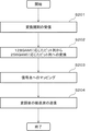
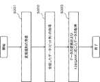
図12は、通信装置200が、変換規則に基づき、所定の変調方式に応じた入力データを、別の所定の変調方式に応じた入力データに変換する場合の処理を示すフローチャートある。図12には、通信装置200が、基地局である場合を例に処理が示されているが、通信装置200が通信端末(ユーザ端末等)の場合も同様の処理が行われる。また、以下では、通信装置200が、128QAMに応じた入力データを、256QAMに応じた入力データに変換する場合の処理例について説明する。
FIG. 12 is a flowchart illustrating processing when the
通信部230は、変換規則導出装置100から送信された変換規則の情報を受信し、記憶部220に変換規則の情報を入力する(ステップS201)。そして、記憶部220には、通信部230から入力された変換規則の情報が格納される。
The
制御信号によって128QAMを使用した変調が指定されて、入力データを送信する場合に、制御部210は、変換規則の情報に基づき、入力データを256QAMに応じたビット列に変換する(ステップS202)。
When modulation using 128QAM is specified by the control signal and the input data is transmitted, the
例えば、制御部210は、入力データを7ビットずつに区切り、記憶部220に格納されている変換規則の情報に基づき、7ビットの入力データを8ビットのデータに変換する。例えば、制御部210は、図9に示す変換規則に基づき、128QAMに応じた7ビットのビット列 “D、x2、x1、C、B、x0、A”を、256QAMに応じた8ビットのビット列“D、y3、y2、C、B、y1、y0、A”に変換する。例えば、制御部210は、図9に示す変換規則に基づき、図3に示す信号点140に対応する図4に示すビット列150“0000001”を、図5に示す信号点180に対応する図7に示すビット列190“01100011”に変換する。
For example, the
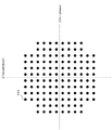
制御部210は、変換されたビット列と、変換されたビット列に対応するメモリアドレスに格納されている256QAMの信号点の位置のI成分の値およびQ成分の値とに基づき、対応する信号点に、変換されたビット列をマッピングする(ステップS203)。そして、制御部210は、マッピングした信号点の位置のI成分の値およびQ成分の値を通信部230に入力する。図13は、256QAMに応じた各信号点のうち、128QAMに応じたデータがマッピングされる信号点の一例を示す図である。例えば、128QAMに応じたデータは、図13に示すように、256QAMに応じた信号点のうち、枠122内の信号点にマッピングされることとなる。図7は、枠122内の各信号点に対応するビット列の情報を示す説明図である。
Based on the converted bit string and the value of the I component and the value of the Q component at the position of the 256QAM signal point stored in the memory address corresponding to the converted bit string, the
通信部230は、マッピングされた信号点の位置のI成分の値およびQ成分の値に基づき、搬送波を変調し、変調後の搬送波を通信装置300に送信する(ステップS204)。
The
なお、制御信号によって256QAMが示されている場合、制御部210は、ビット列を変換しない。
When 256QAM is indicated by the control signal, the
図14は、通信装置300が、変換規則に基づき、所定の変調方式の受信データを、別の所定の変調方式の受信データに変換する処理を示すフローチャートである。図14には、通信装置300が、基地局である場合を例に処理が示されているが、通信装置300が通信端末(ユーザ端末等)の場合も同様の処理が行われる。また、以下では、通信装置300が、256QAMに応じた受信データを、128QAMに応じた受信データに変換する場合の処理例について説明する。
FIG. 14 is a flowchart illustrating processing in which the
通信部330は、変換規則導出装置100から変換規則の情報を受信し、記憶部320に、変換規則の情報を入力する(ステップS301)。そして、記憶部320には、通信部330から入力された変換規則の情報が格納される。
The
通信部330が256QAMに変調された信号を受信した場合に、制御部310は、受信した信号に基づき、受信した信号に含まれるデータがマッピングされた信号点の位置のI成分の値およびQ成分の値を取得する。そして、制御部310は、取得したI成分の値およびQ成分の値に対応する記憶部320のメモリアドレスを参照し、受信した256QAMに応じたデータ(ビット列)として、当該メモリアドレスの値を取得する(ステップS302)。
When the
制御信号によって、128QAMであることが示されている場合に、制御部310は、変換規則の情報に基づき、256QAMに応じたデータを、128QAMに応じたデータに変換し、128QAMに応じたデータを取得する(ステップS303)。例えば、制御部310は、図9に示す変換規則に基づき、256QAMに応じた8ビットのビット列“D、y3、y2、C、B、y1、y0、A”を、128QAMに応じた7ビットのビット列 “D、x2、x1、C、B、x0、A”に変換する。例えば、制御部310は、図9に示す変換規則に基づき、図5に示す信号点180に対応する図7に示すビット列190“01100011”を変換し、図3に示す信号点140に対応する図4に示すビット列150“0000001”を取得する。なお、制御信号によって、256QAMであることが示されている場合に、制御部310は、ビット列を変換しない。
When the control signal indicates that it is 128QAM, based on the conversion rule information, the
なお、変換規則導出装置100は、通信装置200に含まれてもよい。また、変換規則導出装置100は、通信装置300に含まれてもよい。
Note that the conversion
本実施形態によれば、変換規則導出装置100は、128QAMに適用可能な変換規則を導出することができる。したがって、通信装置200は、変換規則に基づき、128QAMに応じたビット列を、256QAMに応じたビット列に変換できる。そして、通信装置200は、256QAMに応じた信号点の位置のI成分の値およびQ成分の値を利用して、128QAMに応じた7ビットの入力データのマッピングを行うことができる。
According to the present embodiment, the conversion
したがって、通信装置200の記憶部220に、384個分の信号点の位置のI成分の値およびQ成分の値(128QAMに用いられる128個分の信号点の位置のI成分の値およびQ成分の値、および256QAMに用いられる256個分の信号点の位置のI成分の値およびQ成分の値)が格納される必要がなく、256QAMに用いられる256個分の信号点の位置のI成分の値およびQ成分の値のみが格納されればよく、記憶部220に格納される情報量が削減される。ワード数に換算すると、記憶部220には、合計768ワードの情報が格納される必要があったところ、合計512ワードの情報のみが格納されればよいこととなる。
Therefore, the
同様に、通信装置300は、変換規則に基づき、256QAMに応じたビット列を、128QAMに応じたビット列に変換できる。したがって、記憶部320には、256QAMに用いられる256個分の信号点の位置のI成分の値およびQ成分の値のみが格納されればよく、記憶部320に格納される情報量が削減される。さらに、通信装置300は、256QAMに応じた信号点の位置のI成分の値およびQ成分の値を参照すれば、複数の変調方式に対応可能であり、受信したデータの変調方式に応じて互いに異なる信号点の位置のI成分の値およびQ成分の値を参照する場合に比べて、参照する情報を選択するための処理負荷を軽減できる。
Similarly, the
また、本実施形態によれば、変換規則導出装置100は、様々な変調方式に対応した変換規則を導出できる。様々な変調方式に対応した変換規則を使用することにより、通信装置200および通信装置300は、様々な変調方式に対応できる。
Further, according to the present embodiment, the conversion
なお、本実施形態では、変換規則導出装置100は、128QAMに応じたデータと256QAMに応じたデータとを相互に変換するための変換規則を導出したが、他の変調方式に対応した変換規則を導出してもよい。例えば、変換規則導出装置100は、128QAMに応じたデータと、64QAMに応じたデータとを相互に変換する変換規則や、64QAMに応じたデータと、32QAMに応じたデータとを相互に変換する変換規則を導出するように構成されていてもよい。
In this embodiment, the conversion
また、本実施形態では、変換規則導出装置100の制御部110は、128QAMに応じたデータと256QAMに応じたデータとを相互に変換する変換規則のみを導出したが、これに限られない。例えば、制御部110は、QPSK、16QAM、32QAM、64QAM、128QAMおよび256QAM等、複数の変調方式に対応した複数個の変換規則を導出してもよい。
In the present embodiment, the
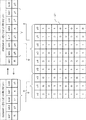
図15は、256QAMに応じたデータ(ビット列)と、64QAMに応じたデータ(ビット列)とを相互に変換するための変換規則の一例を示す図である。図16は、256QAMに応じたデータ(ビット列)と、32QAMに応じたデータ(ビット列)とを相互に変換するための変換規則の一例を示す図である。図17は、256QAMに応じたデータ(ビット列)と、16QAMに応じたデータ(ビット列)とを相互に変換するための変換規則の一例を示す図である。図18は、256QAMに応じたデータ(ビット列)と、QPSKに応じたデータ(ビット列)とを相互に変換するための変換規則の一例を示す図である。図15、図16、図17および図18は、本実施形態の一変形例の説明図である。 FIG. 15 is a diagram illustrating an example of a conversion rule for mutually converting data (bit string) according to 256QAM and data (bit string) according to 64QAM. FIG. 16 is a diagram illustrating an example of a conversion rule for mutually converting data (bit string) according to 256QAM and data (bit string) according to 32QAM. FIG. 17 is a diagram illustrating an example of a conversion rule for mutually converting data (bit string) according to 256QAM and data (bit string) according to 16QAM. FIG. 18 is a diagram illustrating an example of a conversion rule for mutually converting data (bit string) according to 256QAM and data (bit string) according to QPSK. FIG. 15, FIG. 16, FIG. 17 and FIG. 18 are explanatory diagrams of a modification of the present embodiment.
例えば、制御部110は、図15、図16、図17および図18に示すように、128QAM用の変換規則だけでなく、64QAMに応じたデータ(6ビット)、32QAMに応じたデータ(5ビット)、16QAMに応じたデータ(4ビット)およびQPSKに応じたデータ(2ビット)のそれぞれと、256QAMに応じたデータ(8ビット)とを相互に変換する変換規則を導出してもよい。
For example, as shown in FIGS. 15, 16, 17, and 18, the
なお、図15、図16、図17および図18では、64QAMに応じたデータ、32QAMに応じたデータ、16QAMに応じたデータおよびQPSKに応じたデータのそれぞれが、実線で示した矢印の方向で、256QAMに応じたデータに変換される。また、図15、図16、図17および図18では、256QAMに応じたデータが、破線で示した矢印の方向で、64QAMに応じたデータ、32QAMに応じたデータ、16QAMに応じたデータおよびQPSKに応じたデータのそれぞれに変換される。 In FIG. 15, FIG. 16, FIG. 17, and FIG. 18, the data according to 64QAM, the data according to 32QAM, the data according to 16QAM, and the data according to QPSK are shown in the directions of arrows indicated by solid lines. It is converted into data corresponding to 256QAM. In FIG. 15, FIG. 16, FIG. 17 and FIG. 18, the data according to 256QAM is the data according to 64QAM, the data according to 32QAM, the data according to 16QAM and the QPSK in the direction of the arrow indicated by the broken line. Is converted into data corresponding to each.
例えば、図15に示す変換規則では、64QAMに応じたビット列および256QAMに応じたビット列に含まれる、A、B、CおよびDに対応する位置のビットの値は、それぞれ同じ値となる。また、64QAMに応じたビット列に含まれるx0およびx1に対応する位置におけるそれぞれのビットの値の組合せに応じて、256QAMに応じたビット列に含まれるy0、y1、y2およびy3に対応する位置におけるそれぞれのビットの値の組合せが決定される。 For example, in the conversion rule shown in FIG. 15, the bit values at positions corresponding to A, B, C, and D included in the bit string corresponding to 64QAM and the bit string corresponding to 256QAM are the same value. Further, according to the combination of the values of the respective bits at the positions corresponding to x0 and x1 included in the bit string corresponding to 64QAM, each at the position corresponding to y0, y1, y2 and y3 included in the bit string corresponding to 256QAM. The combination of the values of the bits is determined.
x0およびx1に対応する位置のビットの値の組合せと、y0、y1、y2およびy3に対応する位置のビットの値の組合せとの関係が、変換規則テーブル121に示されている。例えば、64QAMに応じたビット列に含まれるx0およびx1に対応する位置のビットの値がすべて“0”の場合(図15に示す変換規則テーブル121の2行目の場合)に、256QAMに応じたビット列に含まれるy3、y2、y1およびy0に対応する位置のそれぞれのビットの値が“1”、“1”、“1”および“1”に決定される。 The relationship between the combination of bit values at positions corresponding to x0 and x1 and the combination of bit values at positions corresponding to y0, y1, y2, and y3 is shown in the conversion rule table 121. For example, when all the values of the bits corresponding to x0 and x1 included in the bit string corresponding to 64QAM are “0” (in the case of the second row of the conversion rule table 121 shown in FIG. 15), 256QAM The values of the respective bits at positions corresponding to y3, y2, y1 and y0 included in the bit string are determined as “1”, “1”, “1” and “1”.
なお、図18には、所定のビットの位置に所定のビットの値が付加されたり、所定のビットの位置におけるビットの値が削除されたりすることにより、QPSKに応じたビット列と、256QAMに応じたビット列とを相互に変換する変換規則が示されている。 In FIG. 18, a bit string corresponding to QPSK and 256QAM are added by adding a predetermined bit value to a predetermined bit position or deleting a bit value at a predetermined bit position. A conversion rule for mutually converting a bit string is shown.
したがって、通信装置200および通信装置300のそれぞれの記憶部に、各多値度に応じた信号点の位置のI成分の値およびQ成分の値が格納される必要が無くなり、格納される情報量がさらに削減される。
Therefore, it is not necessary to store the value of the I component and the value of the Q component at the position of the signal point corresponding to each multilevel in each storage unit of the
例えば、QPSK、16QAM、32QAM、64QAM、128QAMおよび256QAMに変調できる通信装置は、それぞれの変調方式に用いられる500個分の信号点の位置のI成分の値およびQ成分の値を格納するための記憶容量、すなわち、1000ワード分の記憶容量を確保する必要がある。しかしながら、上述した複数の変換規則の情報が格納されることにより、通信装置は、256QAMに用いられる256個分の信号点の位置のI成分の値およびQ成分の値を格納するための記憶容量、すなわち、512ワード分の記憶容量のみを確保すればよい。すなわち、本変形例では、変調できる多値度数が多く、また、多値度が高位であるほど、通信装置に格納される情報量が削減されるという効果が発揮される。 For example, a communication apparatus that can modulate to QPSK, 16QAM, 32QAM, 64QAM, 128QAM, and 256QAM stores I component values and Q component values at the positions of 500 signal points used in the respective modulation schemes. It is necessary to secure a storage capacity, that is, a storage capacity for 1000 words. However, by storing the information on the plurality of conversion rules described above, the communication apparatus can store the I component value and the Q component value at the positions of 256 signal points used in 256QAM. That is, only a storage capacity for 512 words needs to be secured. That is, in this modified example, the effect is that the amount of information stored in the communication device is reduced as the number of multi-values that can be modulated is larger and the multi-value is higher.
また、変換規則導出装置100の制御部110は、通信装置200および通信装置300が対応可能な最高位の多値度の変調方式用の変換規則を導出するように構成されていてもよい。
Further, the
例えば、通信装置200が、最高位の多値度の変調方式として、512QAMに対応可能な場合、制御部110は、例えば、512QAMよりも多値度が低位となる変調方式に応じたデータを、512QAMに応じたデータに変換する変換規則を導出するように構成されていてもよい。
For example, when the
このように構成されることにより、記憶部220には、最高位の多値度の変換規則の情報のみが格納されることとなり、記憶部220に格納される情報量が削減される。また、制御部110は、複数の変換規則を導出する必要がなくなり、制御部110の処理負荷を低減することもできる。
With this configuration, only the highest multilevel conversion rule information is stored in the
なお、通信装置200および通信装置300は、予め通信装置200および通信装置300が対応可能な最高位の多値度の変調方式を示す情報を変換規則導出装置100に送信するように構成されていてもよい。そして、変換規則導出装置100は、対応可能な最高位の多値度の変調方式を示す情報を受信し、制御部110は、受信した最高位の多値度の変調方式を示す情報に基づき、最高位の多値度の変調方式用の変換規則を導出するように構成されていてもよい。
Note that the
また、通信装置200の通信部230および通信装置300の通信部330は、変換規則の導出要求を変換規則導出装置100に送信するように構成されていてもよい。変換規則導出装置100は、当該導出要求に応じて、変換規則を導出するように構成されていてもよい。
The
そのような構成によれば、要求があった場合にのみ変換規則導出装置100が変換規則を導出するため、変換規則導出装置100の処理負荷を低減できる。
According to such a configuration, since the conversion
例えば、通信装置200に送信すべき送信データが生じた場合に、通信部230が変換規則導出装置100に導出要求を送信する。また、例えば、通信装置300が通信装置200から信号を受信した場合に、通信部330が変換規則導出装置100に導出要求を送信する。そして、変換規則導出装置100は、当該導出要求を受信し、導出要求に応じて変換規則を導出するように構成されていてもよい。
For example, when transmission data to be transmitted to the
<第2の実施形態>
図19は、第2の実施形態の通信システム2の構成例を示すブロック図である。
<Second Embodiment>
FIG. 19 is a block diagram illustrating a configuration example of the communication system 2 according to the second embodiment.
通信システム2は、変換規則導出装置100Aと、変換規則導出装置100Bと、送信側の通信装置200と、受信側の通信装置300とを含む。変換規則導出装置100Aおよび通信装置200と、変換規則導出装置100Bおよび通信装置300と、通信装置200および通信装置300とはそれぞれ互いに、無線伝送路または有線伝送路を介して、通信可能に接続されている。
The communication system 2 includes a conversion
変換規則導出装置100Aおよび変換規則導出装置100Bの構成は、第1の実施形態の変換規則導出装置100の構成と同様である。また、通信装置200の構成は、第1の実施形態の通信装置200の構成と同様である。また、通信装置300の構成は、第1の実施形態の通信装置300と同様である。
The configuration of the conversion
変換規則導出装置100Aの出力部130は、導出した変換規則の情報を通信装置200に送信する。また、変換規則導出装置100Bの出力部130は、導出した変換規則の情報を通信装置300に送信する。
The
本実施形態によれば、複数の通信装置のそれぞれに変換規則導出装置が接続され、それぞれの変換規則導出装置が、導出した変換規則の情報をそれぞれの通信装置に送信することにより、変換規則導出装置の処理負荷を分散できる。 According to the present embodiment, a conversion rule deriving device is connected to each of a plurality of communication devices, and each conversion rule deriving device transmits information of the derived conversion rule to each communication device, whereby conversion rule derivation is performed. The processing load of the device can be distributed.
<第3の実施形態>
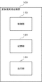
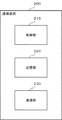
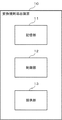
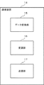
図20は、第3の実施形態の変換規則導出装置10の構成例を示すブロック図である。図20に示すように、変換規則導出装置10は、記憶部11と、制御部12と、提供部13とを含む。
<Third Embodiment>
FIG. 20 is a block diagram illustrating a configuration example of the conversion
記憶部11は、例えば、図2に示す第1の実施形態における記憶部120に相当する。制御部12は、例えば、図2に示す第1の実施形態における制御部110に相当する。提供部13は、例えば、図2に示す第1の実施形態における出力部130に相当する。
The
記憶部11には、通信装置が対応可能な複数のデジタル変調方式において、各デジタル変調方式の信号空間ダイヤグラムにおける信号点に応じた値が当該信号点に対応するビット列に対応付けられて記憶されている。なお、通信装置は、例えば、図1に示す第1の実施形態における通信装置200や通信装置300に相当する。
The
制御部12は、記憶部11に記憶されている値に基づいて、信号空間ダイヤグラムにおいて、第1のデジタル変調方式における各信号点のうち、第2のデジタル変調方式における信号点と重複する信号点に対応するビット列と、第2のデジタル変調方式において当該信号点と重複する信号点に対応するビット列とを相互に変換するための変換規則を導出する。
Based on the value stored in the
提供部13は、制御部12が導出した変換規則を通信装置に提供する。
The providing
本実施形態によれば、変換規則導出装置10には、通信装置が対応可能な複数のデジタル変調方式において、各デジタル変調方式の信号空間ダイヤグラムにおける信号点に応じた値が当該信号点に対応するビット列に対応付けられて記憶されている。そして、変換規則導出装置10は、当該値に基づいて、信号空間ダイヤグラムにおいて、第1のデジタル変調方式における各信号点のうち、第2のデジタル変調方式における信号点と重複する信号点に対応するビット列と、第2のデジタル変調方式において当該信号点と重複する信号点に対応するビット列とを相互に変換するための変換規則を導出し、導出した変換規則を通信装置に提供する。したがって、通信装置が、変換規則に基づきビット列を変換できるため、幅広い変調方式に対応でき、かつ、マッピングに必要な情報量を削減できる。
According to the present embodiment, the conversion
<第4の実施形態>
図21は、第4の実施形態の通信装置14の構成例を示すブロック図である。図21に示すように、通信装置14は、データ変換部15と、変調部16と、送信部17とを含む。
<Fourth Embodiment>
FIG. 21 is a block diagram illustrating a configuration example of the
データ変換部15は、例えば、図8に示す第1の実施形態における制御部210に相当する。変調部16および送信部17は、例えば、図8に示す第1の実施形態における通信部230に相当する。
The data conversion unit 15 corresponds to, for example, the
データ変換部15は、信号空間ダイヤグラムにおける信号配置に基づき、第1のデジタル変調方式の各信号点の値に応じたビット列と、当該各信号点に重複する、第2のデジタル変調方式における各信号点の値に応じたビット列とを相互に変換するための変換規則に基づいて、第1のデジタル変調方式に応じた送信用データを第2のデジタル変調方式に応じた変換後データに変換する。 Based on the signal arrangement in the signal space diagram, the data conversion unit 15 includes a bit string corresponding to the value of each signal point in the first digital modulation method and each signal in the second digital modulation method that overlaps each signal point. Based on the conversion rule for mutually converting the bit string corresponding to the value of the point, the transmission data corresponding to the first digital modulation method is converted to the converted data corresponding to the second digital modulation method.
変調部16は、変換後データに、第2のデジタル変調方式で変調を施して送信信号を生成する。 The modulation unit 16 modulates the converted data by the second digital modulation method to generate a transmission signal.
送信部17は、送信信号を送信する。
The
本実施形態によれば、通信装置14は、信号空間ダイヤグラムにおける信号配置に基づき、第1のデジタル変調方式の各信号点の値に応じたビット列と、当該各信号点に重複する、第2のデジタル変調方式における各信号点の値に応じたビット列とを相互に変換するための変換規則に基づいて、第1のデジタル変調方式に応じた送信用データを第2のデジタル変調方式に応じた変換後データに変換する。そして、通信装置14は、変換後データに、第2のデジタル変調方式で変調を施して送信信号を生成し、送信信号を送信する。したがって、通信装置14が、変換規則に基づきビット列を変換できるため、幅広い変調方式に対応でき、かつ、マッピングに必要な情報量を削減できる。
According to this embodiment, the
<第5の実施形態>
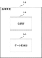
図22は、第5の実施形態の通信装置18の構成例を示すブロック図である。図22に示すように、通信装置18は、復調部19と、データ変換部20とを含む。
<Fifth Embodiment>
FIG. 22 is a block diagram illustrating a configuration example of the
復調部19およびデータ変換部20は、例えば、図10に示す第1の実施形態における制御部310に相当する。
The
復調部19は、受信した送信信号を送信信号に応じた復調方式で変換後データに復調する。
The
データ変換部20は、信号空間ダイヤグラムにおける信号配置に基づき、第1のデジタル変調方式の各信号点の値に応じたビット列と、当該各信号点に重複する、第2のデジタル変調方式における各信号点の値に応じたビット列とを相互に変換するための変換規則に基づいて、第2のデジタル変調方式に応じた変換後データを第1のデジタル変調方式に応じた送信用データに変換する。
Based on the signal arrangement in the signal space diagram, the
本実施形態によれば、通信装置18は、受信した送信信号を送信信号に応じた復調方式で変換後データに復調し、信号空間ダイヤグラムにおける信号配置に基づき、第1のデジタル変調方式の各信号点の値に応じたビット列と、当該各信号点に重複する、第2のデジタル変調方式における各信号点の値に応じたビット列とを相互に変換するための変換規則に基づいて、第2のデジタル変調方式に応じた変換後データを第1のデジタル変調方式に応じた送信用データに変換する。したがって、通信装置18が、変換規則に基づきビット列を変換できるため、幅広い変調方式に対応でき、かつ、マッピングに必要な情報量を削減できる。
According to the present embodiment, the
以上、本発明の実施形態を説明したが、本発明は、上記したそれぞれの実施形態に限定されるものではない。本発明は、各実施形態の変形・置換・調整に基づいて実施できる。また、本発明は、各実施形態を任意に組合せて実施することもできる。すなわち、本発明は、本明細書の全ての開示内容、技術的思想に従って実現できる各種変形、修正を含む。なお、各図面に付記した図面参照符号は、理解を助けるための一例として各要素に便宜上付記したものであり、本発明を図示の態様に限定することを意図するものではない。 As mentioned above, although embodiment of this invention was described, this invention is not limited to each above-mentioned embodiment. The present invention can be implemented based on modifications, substitutions, and adjustments of the embodiments. The present invention can also be implemented by arbitrarily combining the embodiments. That is, the present invention includes various modifications and corrections that can be realized in accordance with all the disclosed contents and technical ideas of the present specification. In addition, the drawing reference numerals attached to each drawing are added to each element for convenience as an example for facilitating understanding, and are not intended to limit the present invention to the illustrated embodiment.
上記の実施形態の一部又は全部は、以下の付記のようにも記載されうるが、以下には限られない。 A part or all of the above-described embodiment can be described as in the following supplementary notes, but is not limited thereto.
(付記1)
通信装置が対応可能な複数のデジタル変調方式において、各デジタル変調方式の信号空間ダイヤグラムにおける信号点に応じた値が前記信号点に対応するビット列に対応付けられて記憶されている記憶手段と、
前記記憶手段に記憶されている前記値に基づいて、前記信号空間ダイヤグラムにおいて、第1のデジタル変調方式における各信号点のうち、第2のデジタル変調方式における信号点と重複する信号点に対応するビット列と、前記第2のデジタル変調方式において前記信号点と重複する信号点に対応するビット列とを相互に変換するための変換規則を導出する制御手段と、
前記制御手段が導出した前記変換規則を前記通信装置に提供する提供手段と、
を備えたことを特徴とする変換規則導出装置。
(Appendix 1)
In a plurality of digital modulation schemes that can be supported by the communication device, storage means that stores values corresponding to signal points in the signal space diagram of each digital modulation scheme in association with bit strings corresponding to the signal points;
Based on the value stored in the storage means, in the signal space diagram, among signal points in the first digital modulation system, corresponding to signal points overlapping with signal points in the second digital modulation system Control means for deriving a conversion rule for mutually converting a bit string and a bit string corresponding to a signal point overlapping with the signal point in the second digital modulation scheme;
Providing means for providing the communication device with the conversion rule derived by the control means;
A conversion rule derivation device characterized by comprising:
(付記2)
前記各デジタル変調方式の信号空間ダイヤグラムにおける信号点に応じた値は、前記記憶手段において、対応するビット列をメモリアドレスとする領域に記憶されている、
付記1に記載の変換規則導出装置。
(Appendix 2)
A value corresponding to a signal point in the signal space diagram of each digital modulation method is stored in the storage unit in an area having a corresponding bit string as a memory address.
The conversion rule deriving device according to
(付記3)
前記制御手段は、前記第1のデジタル変調方式と前記第2のデジタル変調方式とにおける前記信号空間ダイヤグラムで互いに重複する信号点のそれぞれに対応するビット列において、値が互いに等しいか否かに基づいて、変換規則を導出する、
付記1または付記2に記載の変換規則導出装置。
(Appendix 3)
The control means is based on whether or not values are equal to each other in bit strings corresponding to signal points overlapping each other in the signal space diagram in the first digital modulation scheme and the second digital modulation scheme. , Derive transformation rules,
The conversion rule deriving device according to
(付記4)
前記制御手段は、前記第1のデジタル変調方式と前記第2のデジタル変調方式とにおける前記信号空間ダイヤグラムで互いに重複する信号点のそれぞれに対応するビット列において、一方のビット列におけるビットと他方のビット列におけるビットとで値が互いに等しい桁がある場合に、一方のビット列における桁の値を他方のビット列における桁に適用する変換規則を導出する、
付記3に記載の変換規則導出装置。
(Appendix 4)
The control means includes a bit string corresponding to each of overlapping signal points in the signal space diagram in the first digital modulation scheme and the second digital modulation scheme, in one bit string and in the other bit string. Deriving a conversion rule that applies a digit value in one bit string to a digit in the other bit string if there are digits in the bit and values that are equal to each other;
The conversion rule derivation device according to attachment 3.
(付記5)
前記制御手段は、前記第1のデジタル変調方式と前記第2のデジタル変調方式とにおける前記信号空間ダイヤグラムで互いに重複する信号点のそれぞれに対応するビット列において、一方のビット列におけるビットと他方のビット列におけるビットとで値が互いに等しくない桁がある場合に、一方のビット列における前記桁の値の組合せに、対応する所定の値の組合せを適用する変換規則を導出する、
付記3または付記4に記載の変換規則導出装置。
(Appendix 5)
The control means includes a bit string corresponding to each of overlapping signal points in the signal space diagram in the first digital modulation scheme and the second digital modulation scheme, in one bit string and in the other bit string. When there are digits whose values are not equal to each other, a conversion rule for deriving a combination of predetermined values corresponding to the combination of the values of the digits in one bit string is derived.
The conversion rule deriving device according to Supplementary Note 3 or
(付記6)
信号空間ダイヤグラムにおける信号配置に基づき、第1のデジタル変調方式の各信号点の値に応じたビット列と、前記各信号点に重複する、第2のデジタル変調方式における各信号点の値に応じたビット列とを相互に変換するための変換規則に基づいて、前記第1のデジタル変調方式に応じた送信用データを前記第2のデジタル変調方式に応じた変換後データに変換するデータ変換手段と、
前記変換後データに、前記第2のデジタル変調方式で変調を施して送信信号を生成する変調手段と、
前記送信信号を送信する送信手段と、
を備えたことを特徴とする通信装置。
(Appendix 6)
Based on the signal arrangement in the signal space diagram, the bit string corresponding to the value of each signal point of the first digital modulation method and the value of each signal point in the second digital modulation method overlapping each signal point Data conversion means for converting transmission data according to the first digital modulation scheme into post-conversion data according to the second digital modulation scheme based on a conversion rule for mutually converting bit strings;
Modulation means for modulating the converted data by the second digital modulation method to generate a transmission signal;
Transmitting means for transmitting the transmission signal;
A communication apparatus comprising:
(付記7)
前記変換規則を導出する変換規則導出装置を含む、
付記6に記載の通信装置。
(Appendix 7)
A conversion rule deriving device for deriving the conversion rule;
The communication device according to attachment 6.
(付記8)
受信した送信信号を前記送信信号に応じた復調方式で変換後データに復調する復調手段と、
信号空間ダイヤグラムにおける信号配置に基づき、第1のデジタル変調方式の各信号点の値に応じたビット列と、前記各信号点に重複する、第2のデジタル変調方式における各信号点の値に応じたビット列とを相互に変換するための変換規則に基づいて、前記第2のデジタル変調方式に応じた変換後データを前記第1のデジタル変調方式に応じた送信用データに変換するデータ変換手段と、
を備えたことを特徴とする通信装置。
(Appendix 8)
Demodulation means for demodulating the received transmission signal into post-conversion data in a demodulation scheme according to the transmission signal;
Based on the signal arrangement in the signal space diagram, the bit string corresponding to the value of each signal point of the first digital modulation method and the value of each signal point in the second digital modulation method overlapping each signal point Data conversion means for converting the converted data according to the second digital modulation scheme into data for transmission according to the first digital modulation scheme, based on a conversion rule for mutually converting bit strings;
A communication apparatus comprising:
(付記9)
前記変換規則を導出する変換規則導出装置を含む、
付記8に記載の通信装置。
(Appendix 9)
A conversion rule deriving device for deriving the conversion rule;
The communication apparatus according to appendix 8.
(付記10)
通信装置が対応可能な複数のデジタル変調方式において、各デジタル変調方式の信号空間ダイヤグラムにおける信号点に応じた値が前記信号点に対応するビット列に対応付けられて記憶されている記憶手段に記憶されている前記値に基づいて、前記信号空間ダイヤグラムにおいて、第1のデジタル変調方式における各信号点のうち、第2のデジタル変調方式における信号点と重複する信号点に対応するビット列と、前記第2のデジタル変調方式において前記信号点と重複する信号点に対応するビット列とを相互に変換するための変換規則を導出し、
導出した前記変換規則を前記通信装置に提供する、
ことを特徴とする変換規則導出提供方法。
(Appendix 10)
In a plurality of digital modulation schemes that can be supported by the communication apparatus, values corresponding to signal points in the signal space diagram of each digital modulation scheme are stored in a storage unit that is stored in association with a bit string corresponding to the signal points. In the signal space diagram, a bit string corresponding to a signal point overlapping with a signal point in the second digital modulation method among the signal points in the first digital modulation method in the signal space diagram, Deriving a conversion rule for mutually converting the signal point and the bit string corresponding to the overlapping signal point in the digital modulation system of
Providing the derived conversion rule to the communication device;
A conversion rule derivation and provision method characterized by the above.
(付記11)
前記各デジタル変調方式の信号空間ダイヤグラムにおける信号点に応じた値が対応付けられているビット列は、前記記憶手段におけるメモリアドレスである
付記10に記載の変換規則導出提供方法。
(Appendix 11)
The conversion rule derivation / providing method according to
(付記12)
コンピュータに、
通信装置が対応可能な複数のデジタル変調方式において、各デジタル変調方式の信号空間ダイヤグラムにおける信号点に応じた値が前記信号点に対応するビット列に対応付けられて記憶されている記憶手段に記憶されている前記値に基づいて、前記信号空間ダイヤグラムにおいて、第1のデジタル変調方式における各信号点のうち、第2のデジタル変調方式における信号点と重複する信号点に対応するビット列と、前記第2のデジタル変調方式において前記信号点と重複する信号点に対応するビット列とを相互に変換するための変換規則を導出する導出処理と、
導出した前記変換規則を前記通信装置に提供する提供処理とを実行させる
ための変換規則導出提供用プログラム。
(Appendix 12)
On the computer,
In a plurality of digital modulation schemes that can be supported by the communication apparatus, values corresponding to signal points in the signal space diagram of each digital modulation scheme are stored in a storage unit that is stored in association with a bit string corresponding to the signal points. In the signal space diagram, a bit string corresponding to a signal point overlapping with a signal point in the second digital modulation method among the signal points in the first digital modulation method in the signal space diagram, A derivation process for deriving a conversion rule for mutually converting a bit string corresponding to a signal point that overlaps the signal point in the digital modulation scheme of
A conversion rule derivation and provision program for executing a provision process of providing the derived conversion rule to the communication device.
(付記13)
前記各デジタル変調方式の信号空間ダイヤグラムにおける信号点に応じた値が対応付けられているビット列は、前記記憶手段におけるメモリアドレスである
付記12に記載の変換規則導出提供用プログラム。
(Appendix 13)
The conversion rule derivation providing program according to
1、2 通信システム
10、100、100A、100B 変換規則導出装置
11、120、220、320 記憶部
12、110 制御部
121 変換規則テーブル
122 枠
13 提供部
130 出力部
14、18、200、300 通信装置
140、160、180 信号点
15、20 データ変換部
150、170、190 ビット列
16 変調部
17 送信部
19 復調部
210、310 制御部
230 通信部
330 通信部
1, 2
Claims (10)
前記記憶手段に記憶されている前記値に基づいて、前記信号空間ダイヤグラムにおいて、第1のデジタル変調方式における各信号点のうち、第2のデジタル変調方式における信号点と重複する信号点に対応するビット列と、前記第2のデジタル変調方式において前記信号点と重複する信号点に対応するビット列とを相互に変換するための変換規則を導出する制御手段と、
前記制御手段が導出した前記変換規則を前記通信装置に提供する提供手段と、
を備えたことを特徴とする変換規則導出装置。 In a plurality of digital modulation schemes that can be supported by the communication device, storage means that stores values corresponding to signal points in the signal space diagram of each digital modulation scheme in association with bit strings corresponding to the signal points;
Based on the value stored in the storage means, in the signal space diagram, among signal points in the first digital modulation system, corresponding to signal points overlapping with signal points in the second digital modulation system Control means for deriving a conversion rule for mutually converting a bit string and a bit string corresponding to a signal point overlapping with the signal point in the second digital modulation scheme;
Providing means for providing the communication device with the conversion rule derived by the control means;
A conversion rule derivation device characterized by comprising:
請求項1に記載の変換規則導出装置。 A value corresponding to a signal point in the signal space diagram of each digital modulation method is stored in the storage unit in an area having a corresponding bit string as a memory address.
The conversion rule deriving device according to claim 1.
請求項1または請求項2に記載の変換規則導出装置。 The control means is based on whether or not values are equal to each other in bit strings corresponding to signal points overlapping each other in the signal space diagram in the first digital modulation scheme and the second digital modulation scheme. , Derive transformation rules,
The conversion rule deriving device according to claim 1 or 2.
請求項3に記載の変換規則導出装置。 The control means includes a bit string corresponding to each of overlapping signal points in the signal space diagram in the first digital modulation scheme and the second digital modulation scheme, in one bit string and in the other bit string. Deriving a conversion rule that applies a digit value in one bit string to a digit in the other bit string if there are digits in the bit and values that are equal to each other;
The conversion rule derivation device according to claim 3.
請求項3または請求項4に記載の変換規則導出装置。 The control means includes a bit string corresponding to each of overlapping signal points in the signal space diagram in the first digital modulation scheme and the second digital modulation scheme, in one bit string and in the other bit string. When there are digits whose values are not equal to each other, a conversion rule for deriving a combination of predetermined values corresponding to the combination of the values of the digits in one bit string is derived.
The conversion rule deriving device according to claim 3 or 4.
前記変換後データに、前記第2のデジタル変調方式で変調を施して送信信号を生成する変調手段と、
前記送信信号を送信する送信手段と、
を備えたことを特徴とする通信装置。 Based on the signal arrangement in the signal space diagram, the bit string corresponding to the value of each signal point of the first digital modulation method and the value of each signal point in the second digital modulation method overlapping each signal point Data conversion means for converting transmission data according to the first digital modulation scheme into post-conversion data according to the second digital modulation scheme based on a conversion rule for mutually converting bit strings;
Modulation means for modulating the converted data by the second digital modulation method to generate a transmission signal;
Transmitting means for transmitting the transmission signal;
A communication apparatus comprising:
請求項6に記載の通信装置。 A conversion rule deriving device for deriving the conversion rule;
The communication apparatus according to claim 6.
信号空間ダイヤグラムにおける信号配置に基づき、第1のデジタル変調方式の各信号点の値に応じたビット列と、前記各信号点に重複する、第2のデジタル変調方式における各信号点の値に応じたビット列とを相互に変換するための変換規則に基づいて、前記第2のデジタル変調方式に応じた変換後データを前記第1のデジタル変調方式に応じた送信用データに変換するデータ変換手段と、
を備えたことを特徴とする通信装置。 Demodulation means for demodulating the received transmission signal into post-conversion data in a demodulation scheme according to the transmission signal;
Based on the signal arrangement in the signal space diagram, the bit string corresponding to the value of each signal point of the first digital modulation method and the value of each signal point in the second digital modulation method overlapping each signal point Data conversion means for converting the converted data according to the second digital modulation scheme into data for transmission according to the first digital modulation scheme, based on a conversion rule for mutually converting bit strings;
A communication apparatus comprising:
請求項8に記載の通信装置。 A conversion rule deriving device for deriving the conversion rule;
The communication apparatus according to claim 8.
導出した前記変換規則を前記通信装置に提供する、
ことを特徴とする変換規則導出提供方法。 In a plurality of digital modulation schemes that can be supported by the communication apparatus, values corresponding to signal points in the signal space diagram of each digital modulation scheme are stored in a storage unit that is stored in association with a bit string corresponding to the signal points. In the signal space diagram, a bit string corresponding to a signal point overlapping with a signal point in the second digital modulation method among the signal points in the first digital modulation method in the signal space diagram, Deriving a conversion rule for mutually converting the signal point and the bit string corresponding to the overlapping signal point in the digital modulation system of
Providing the derived conversion rule to the communication device;
A conversion rule derivation and provision method characterized by the above.
Priority Applications (1)
| Application Number | Priority Date | Filing Date | Title |
|---|---|---|---|
| JP2016166884A JP6849347B2 (en) | 2016-08-29 | 2016-08-29 | Conversion rule derivation device, communication device, conversion rule derivation provision method |
Applications Claiming Priority (1)
| Application Number | Priority Date | Filing Date | Title |
|---|---|---|---|
| JP2016166884A JP6849347B2 (en) | 2016-08-29 | 2016-08-29 | Conversion rule derivation device, communication device, conversion rule derivation provision method |
Publications (2)
| Publication Number | Publication Date |
|---|---|
| JP2018037726A true JP2018037726A (en) | 2018-03-08 |
| JP6849347B2 JP6849347B2 (en) | 2021-03-24 |
Family
ID=61567762
Family Applications (1)
| Application Number | Title | Priority Date | Filing Date |
|---|---|---|---|
| JP2016166884A Active JP6849347B2 (en) | 2016-08-29 | 2016-08-29 | Conversion rule derivation device, communication device, conversion rule derivation provision method |
Country Status (1)
| Country | Link |
|---|---|
| JP (1) | JP6849347B2 (en) |
Citations (6)
| Publication number | Priority date | Publication date | Assignee | Title |
|---|---|---|---|---|
| JPH11261537A (en) * | 1998-11-26 | 1999-09-24 | Fujitsu Ltd | Multimedia multiplex transmission method and apparatus |
| JP2001285378A (en) * | 2000-03-31 | 2001-10-12 | Toshiba Corp | Transmission mapping device that can support multiple modulation schemes |
| WO2007018155A1 (en) * | 2005-08-05 | 2007-02-15 | Matsushita Electric Industrial Co., Ltd. | Wireless communication apparatus and wireless communication method |
| JP2008545305A (en) * | 2005-06-29 | 2008-12-11 | 松下電器産業株式会社 | Method for generating modulation symbols according to different symbol mapping schemes using a symbol mapper that uses a certain symbol mapping scheme, and method for generating symbol mapping schemes |
| WO2011068119A1 (en) * | 2009-12-01 | 2011-06-09 | 日本電気株式会社 | Data transmission method, data reception method, data modulation device, data demodulation device |
| JP2014143532A (en) * | 2013-01-23 | 2014-08-07 | Nec Access Technica Ltd | Mapping device and method thereof |
-
2016
- 2016-08-29 JP JP2016166884A patent/JP6849347B2/en active Active
Patent Citations (6)
| Publication number | Priority date | Publication date | Assignee | Title |
|---|---|---|---|---|
| JPH11261537A (en) * | 1998-11-26 | 1999-09-24 | Fujitsu Ltd | Multimedia multiplex transmission method and apparatus |
| JP2001285378A (en) * | 2000-03-31 | 2001-10-12 | Toshiba Corp | Transmission mapping device that can support multiple modulation schemes |
| JP2008545305A (en) * | 2005-06-29 | 2008-12-11 | 松下電器産業株式会社 | Method for generating modulation symbols according to different symbol mapping schemes using a symbol mapper that uses a certain symbol mapping scheme, and method for generating symbol mapping schemes |
| WO2007018155A1 (en) * | 2005-08-05 | 2007-02-15 | Matsushita Electric Industrial Co., Ltd. | Wireless communication apparatus and wireless communication method |
| WO2011068119A1 (en) * | 2009-12-01 | 2011-06-09 | 日本電気株式会社 | Data transmission method, data reception method, data modulation device, data demodulation device |
| JP2014143532A (en) * | 2013-01-23 | 2014-08-07 | Nec Access Technica Ltd | Mapping device and method thereof |
Also Published As
| Publication number | Publication date |
|---|---|
| JP6849347B2 (en) | 2021-03-24 |
Similar Documents
| Publication | Publication Date | Title |
|---|---|---|
| KR102367380B1 (en) | non-uniform(NU) constellation | |
| CN102413094B (en) | Method for constructing multimode quadrature amplitude modulation (QAM) uniform constellation diagram label and modulator | |
| JP2017528974A (en) | System and method for generating a codebook with fewer projections per complex dimension and use thereof | |
| EP3503489A1 (en) | Modulation method, demodulation method, related device and system | |
| WO2010029643A1 (en) | Transmission device, reception device, transmission method, and reception method | |
| US9401833B2 (en) | Method and apparatus for transmitting/receiving signal in wireless communication system | |
| JP4700107B2 (en) | Method and transmitter for generating modulation symbols, and computer-readable medium storing instructions for generating modulation symbols | |
| WO2022252952A1 (en) | Data transmission method, device, and storage medium | |
| CN112583759A (en) | Information transmission method and communication device | |
| KR100795226B1 (en) | Digital signal modulation method and apparatus using triangular constellation | |
| JP4716048B2 (en) | Modulation / demodulation method, modulation apparatus and demodulation apparatus | |
| JP2011217181A (en) | Transmitter, and receiver | |
| CN103841075A (en) | Method, device and system for modulation mapping, and method and device for demapping | |
| JP5868271B2 (en) | Optical transmission device and optical transmission method | |
| CN105634851B (en) | Measuring device capable of generating custom data files for quadrature amplitude modulation signals and its modulation method | |
| WO2019225311A1 (en) | Optical communication system, optical transmitter and optical receiver | |
| JP6849347B2 (en) | Conversion rule derivation device, communication device, conversion rule derivation provision method | |
| US7630453B2 (en) | Multi-level modulation method and system | |
| JP5113897B2 (en) | Method and apparatus for generating a mapping from data words to modulation symbols of a 16QAM constellation, and computer readable medium storing instructions for performing the same | |
| JP2008177644A (en) | Multilevel quadrature amplitude modulator | |
| JP6132331B2 (en) | Mapping apparatus and method | |
| JP6075446B2 (en) | Demodulator, demodulation method and program | |
| CN202818363U (en) | Multi-mode QAM unified constellation diagram label modulator | |
| JP2015188167A (en) | Communication apparatus and mapping method | |
| JP3738997B2 (en) | Communication method |
Legal Events
| Date | Code | Title | Description |
|---|---|---|---|
| A711 | Notification of change in applicant |
Free format text: JAPANESE INTERMEDIATE CODE: A712 Effective date: 20170706 |
|
| A621 | Written request for application examination |
Free format text: JAPANESE INTERMEDIATE CODE: A621 Effective date: 20190716 |
|
| A977 | Report on retrieval |
Free format text: JAPANESE INTERMEDIATE CODE: A971007 Effective date: 20200729 |
|
| A131 | Notification of reasons for refusal |
Free format text: JAPANESE INTERMEDIATE CODE: A131 Effective date: 20200825 |
|
| A521 | Request for written amendment filed |
Free format text: JAPANESE INTERMEDIATE CODE: A523 Effective date: 20200928 |
|
| TRDD | Decision of grant or rejection written | ||
| A01 | Written decision to grant a patent or to grant a registration (utility model) |
Free format text: JAPANESE INTERMEDIATE CODE: A01 Effective date: 20210209 |
|
| A61 | First payment of annual fees (during grant procedure) |
Free format text: JAPANESE INTERMEDIATE CODE: A61 Effective date: 20210304 |
|
| R150 | Certificate of patent or registration of utility model |
Ref document number: 6849347 Country of ref document: JP Free format text: JAPANESE INTERMEDIATE CODE: R150 |