JP2018026662A - Communication device, communication method, and program - Google Patents
Communication device, communication method, and program Download PDFInfo
- Publication number
- JP2018026662A JP2018026662A JP2016156464A JP2016156464A JP2018026662A JP 2018026662 A JP2018026662 A JP 2018026662A JP 2016156464 A JP2016156464 A JP 2016156464A JP 2016156464 A JP2016156464 A JP 2016156464A JP 2018026662 A JP2018026662 A JP 2018026662A
- Authority
- JP
- Japan
- Prior art keywords
- transmitted
- communication
- reference signal
- unit
- downlink
- Prior art date
- Legal status (The legal status is an assumption and is not a legal conclusion. Google has not performed a legal analysis and makes no representation as to the accuracy of the status listed.)
- Pending
Links
Images


Classifications
-
- H—ELECTRICITY
- H04—ELECTRIC COMMUNICATION TECHNIQUE
- H04J—MULTIPLEX COMMUNICATION
- H04J11/00—Orthogonal multiplex systems, e.g. using WALSH codes
- H04J11/0069—Cell search, i.e. determining cell identity [cell-ID]
- H04J11/0079—Acquisition of downlink reference signals, e.g. detection of cell-ID
-
- H—ELECTRICITY
- H04—ELECTRIC COMMUNICATION TECHNIQUE
- H04W—WIRELESS COMMUNICATION NETWORKS
- H04W72/00—Local resource management
- H04W72/50—Allocation or scheduling criteria for wireless resources
- H04W72/54—Allocation or scheduling criteria for wireless resources based on quality criteria
- H04W72/542—Allocation or scheduling criteria for wireless resources based on quality criteria using measured or perceived quality
-
- H—ELECTRICITY
- H04—ELECTRIC COMMUNICATION TECHNIQUE
- H04L—TRANSMISSION OF DIGITAL INFORMATION, e.g. TELEGRAPHIC COMMUNICATION
- H04L25/00—Baseband systems
- H04L25/02—Details ; arrangements for supplying electrical power along data transmission lines
- H04L25/0202—Channel estimation
-
- H—ELECTRICITY
- H04—ELECTRIC COMMUNICATION TECHNIQUE
- H04L—TRANSMISSION OF DIGITAL INFORMATION, e.g. TELEGRAPHIC COMMUNICATION
- H04L27/00—Modulated-carrier systems
- H04L27/0006—Assessment of spectral gaps suitable for allocating digitally modulated signals, e.g. for carrier allocation in cognitive radio
-
- H—ELECTRICITY
- H04—ELECTRIC COMMUNICATION TECHNIQUE
- H04L—TRANSMISSION OF DIGITAL INFORMATION, e.g. TELEGRAPHIC COMMUNICATION
- H04L5/00—Arrangements affording multiple use of the transmission path
- H04L5/003—Arrangements for allocating sub-channels of the transmission path
- H04L5/0048—Allocation of pilot signals, i.e. of signals known to the receiver
-
- H—ELECTRICITY
- H04—ELECTRIC COMMUNICATION TECHNIQUE
- H04W—WIRELESS COMMUNICATION NETWORKS
- H04W16/00—Network planning, e.g. coverage or traffic planning tools; Network deployment, e.g. resource partitioning or cells structures
- H04W16/14—Spectrum sharing arrangements between different networks
-
- H—ELECTRICITY
- H04—ELECTRIC COMMUNICATION TECHNIQUE
- H04W—WIRELESS COMMUNICATION NETWORKS
- H04W56/00—Synchronisation arrangements
- H04W56/001—Synchronization between nodes
-
- H—ELECTRICITY
- H04—ELECTRIC COMMUNICATION TECHNIQUE
- H04W—WIRELESS COMMUNICATION NETWORKS
- H04W72/00—Local resource management
- H04W72/04—Wireless resource allocation
-
- H—ELECTRICITY
- H04—ELECTRIC COMMUNICATION TECHNIQUE
- H04W—WIRELESS COMMUNICATION NETWORKS
- H04W72/00—Local resource management
- H04W72/50—Allocation or scheduling criteria for wireless resources
- H04W72/54—Allocation or scheduling criteria for wireless resources based on quality criteria
-
- H—ELECTRICITY
- H04—ELECTRIC COMMUNICATION TECHNIQUE
- H04W—WIRELESS COMMUNICATION NETWORKS
- H04W76/00—Connection management
- H04W76/20—Manipulation of established connections
- H04W76/28—Discontinuous transmission [DTX]; Discontinuous reception [DRX]
Abstract
Description
本開示は、通信装置、通信方法、及びプログラムに関する。 The present disclosure relates to a communication device, a communication method, and a program.
セルラー移動通信の無線アクセス方式および無線ネットワーク(以下、「Long Term Evolution(LTE)」、「LTE-Advanced(LTE-A)」、「LTE-Advanced Pro(LTE-A Pro)」、「New Radio(NR)」、「New Radio Access Technology(NRAT)」、「Evolved Universal Terrestrial Radio Access(EUTRA)」、または「Further EUTRA(FEUTRA)」とも称する。)が、第三世代パートナーシッププロジェクト(3rd Generation Partnership Project: 3GPP)において検討されている。なお、以下の説明において、LTEは、LTE-A、LTE-A Pro、およびEUTRAを含み、NRは、NRAT、およびFEUTRAを含む。LTEおよびNRでは、基地局装置(基地局)はeNodeB(evolved NodeB)、端末装置(移動局、移動局装置、端末)はUE(User Equipment)とも称する。LTEおよびNRは、基地局装置がカバーするエリアをセル状に複数配置するセルラー通信システムである。単一の基地局装置は複数のセルを管理してもよい。 Wireless access methods and networks for cellular mobile communications (Long Term Evolution (LTE), LTE-Advanced (LTE-A), LTE-Advanced Pro (LTE-A Pro)), New Radio ( NR), “New Radio Access Technology (NRAT)”, “Evolved Universal Terrestrial Radio Access (EUTRA)”, or “Further EUTRA (FEUTRA)”), the 3rd Generation Partnership Project: 3GPP). In the following description, LTE includes LTE-A, LTE-A Pro, and EUTRA, and NR includes NRAT and FEUTRA. In LTE and NR, a base station device (base station) is also called eNodeB (evolved NodeB), and a terminal device (mobile station, mobile station device, terminal) is also called UE (User Equipment). LTE and NR are cellular communication systems in which a plurality of areas covered by a base station apparatus are arranged in a cell shape. A single base station apparatus may manage a plurality of cells.
LAAは、LTEの1つの技術であり、免許不要帯域(unlicensed band)において、LTE運用を行う方式である。LAAにおいて、他のノードや無線システムとの共存が重要とされており、送信する前にチャネルのセンシングを行うLBT(Listen Before Talk)や断続的送信(discontinuous transmission)などの機能が要求されている。LAAの詳細は、非特許文献1に開示されている。
LAA is one of the technologies of LTE and is a method for performing LTE operation in an unlicensed band. In LAA, coexistence with other nodes and wireless systems is important, and functions such as LBT (Listen Before Talk) and discontinuous transmission that perform channel sensing before transmission are required. . Details of LAA are disclosed in
NRは、LTEに対する次世代の無線アクセス方式として、LTEとは異なるRAT(Radio Access Technology)である。NRは、eMBB(Enhanced mobile broadband)、mMTC(Massive machine type communications)およびURLLC(Ultra reliable and low latency communications)を含む様々なユースケースに対応できるアクセス技術である。NRは、それらのユースケースにおける利用シナリオ、要求条件、および配置シナリオなどに対応する技術フレームワークを目指して検討される。 NR is a radio access technology (RAT) different from LTE as a next-generation radio access scheme for LTE. NR is an access technology that can handle various use cases including eMBB (Enhanced mobile broadband), mMTC (Massive machine type communications), and URLLC (Ultra reliable and low latency communications). NR is examined with the aim of a technology framework that addresses usage scenarios, requirements, and deployment scenarios in those use cases.
ところで、免許帯域で運用されるLTEでは、全てのサブフレームにおいて下りリンクの無線リソースで送信される参照信号に基づいて、下りリンクの同期およびRLM(Radio Link Monitoring)測定が行われている。これに対して、LAAやNRにおいては、所謂サブフレームのような単位期間の全てにおいて、参照信号が下りリンクの無線リソースに含まれているとは限らず、一部の単位期間においては、参照信号が下りリンクの無線リソースに含まれない場合がある。そのため、LAAやNRにおいては、端末装置は、全ての単位期間において参照信号を常に検出することが可能な状態にあるとは限らず、安定した下りリンクの同期やRLM測定を行うことが困難となる場合がある。 By the way, in LTE operated in the licensed band, downlink synchronization and RLM (Radio Link Monitoring) measurement are performed based on reference signals transmitted by downlink radio resources in all subframes. On the other hand, in LAA and NR, reference signals are not always included in downlink radio resources in all unit periods such as so-called subframes. A signal may not be included in downlink radio resources. For this reason, in LAA and NR, the terminal device is not always in a state where it can always detect the reference signal in all unit periods, and it is difficult to perform stable downlink synchronization and RLM measurement. There is a case.
そこで、本開示では、全ての単位期間において参照信号が送信されるとは限らない状況下においても、より安定した同期やRLM測定を実現することが可能な、通信装置、通信方法、及びプログラムについて提案する。 Therefore, in the present disclosure, a communication device, a communication method, and a program that can realize more stable synchronization and RLM measurement even in a situation where a reference signal is not transmitted in all unit periods. suggest.
本開示によれば、無線通信を行う通信部と、断続的に送信される参照信号に基づき、当該参照信号が送信される期間を対象として、前記無線通信の通信品質に関する情報を取得する取得部と、を備える、通信装置が提供される。 According to the present disclosure, a communication unit that performs wireless communication, and an acquisition unit that acquires information related to communication quality of the wireless communication based on a reference signal that is intermittently transmitted, for a period in which the reference signal is transmitted A communication device is provided.
また、本開示によれば、無線通信を行う通信部と、断続的に送信され、かつ前記無線通信の通信品質の測定に利用される参照信号について、当該参照信号が送信される期間を直接的または間接的に特定するための情報が、端末装置に送信されるように制御する制御部と、を備える、通信装置が提供される。 In addition, according to the present disclosure, a reference signal transmission period is directly set for a communication unit that performs wireless communication and a reference signal that is intermittently transmitted and used for measurement of communication quality of the wireless communication. Alternatively, a communication device is provided that includes a control unit that controls information to be indirectly specified to be transmitted to the terminal device.
また、本開示によれば、無線通信を行うことと、コンピュータが、断続的に送信される参照信号に基づき、当該参照信号が送信される期間を対象として、前記無線通信の通信品質に関する情報を取得することと、を含む、通信方法が提供される。 Further, according to the present disclosure, information related to communication quality of the wireless communication is performed based on a reference signal transmitted intermittently by the computer and a period during which the reference signal is transmitted. Obtaining a communication method.
また、本開示によれば、無線通信を行うことと、コンピュータが、断続的に送信され、かつ前記無線通信の通信品質の測定に利用される参照信号について、当該参照信号が送信される期間を直接的または間接的に特定するための情報が、端末装置に送信されるように制御することと、を含む、通信方法が提供される。 Further, according to the present disclosure, for a reference signal that is transmitted wirelessly and a computer is intermittently transmitted and used for measurement of the communication quality of the wireless communication, a period in which the reference signal is transmitted is set. There is provided a communication method including controlling information for specifying directly or indirectly to be transmitted to a terminal device.
また、本開示によれば、コンピュータに、無線通信を行うことと、断続的に送信される参照信号に基づき、当該参照信号が送信される期間を対象として、前記無線通信の通信品質に関する情報を取得することと、を実行させる、プログラムが提供される。 Further, according to the present disclosure, information related to the communication quality of the wireless communication is performed based on the reference signal transmitted intermittently and the reference signal transmitted intermittently to the computer. A program is provided for causing and executing.
また、本開示によれば、コンピュータに、無線通信を行うことと、断続的に送信され、かつ前記無線通信の通信品質の測定に利用される参照信号について、当該参照信号が送信される期間を直接的または間接的に特定するための情報が、端末装置に送信されるように制御することと、を実行させる、プログラムが提供される。 Further, according to the present disclosure, for a reference signal that is wirelessly transmitted to a computer and intermittently transmitted and used for measurement of the communication quality of the wireless communication, a period in which the reference signal is transmitted is set. There is provided a program for performing control so that information for specifying directly or indirectly is transmitted to a terminal device.
以上説明したように本開示によれば、全ての単位期間において参照信号が下りリンクの無線リソースに含まれているとは限らない状況下においても、より安定した下りリンクの同期やRLM測定を実現することが可能な、通信装置、通信方法、及びプログラムが提供される。 As described above, according to the present disclosure, more stable downlink synchronization and RLM measurement are realized even in a situation where the reference signal is not necessarily included in the downlink radio resource in all unit periods. A communication device, a communication method, and a program are provided.
なお、上記の効果は必ずしも限定的なものではなく、上記の効果とともに、または上記の効果に代えて、本明細書に示されたいずれかの効果、または本明細書から把握され得る他の効果が奏されてもよい。 Note that the above effects are not necessarily limited, and any of the effects shown in the present specification, or other effects that can be grasped from the present specification, together with or in place of the above effects. May be played.
以下に添付図面を参照しながら、本開示の好適な実施の形態について詳細に説明する。なお、本明細書及び図面において、実質的に同一の機能構成を有する構成要素については、同一の符号を付することにより重複説明を省略する。 Hereinafter, preferred embodiments of the present disclosure will be described in detail with reference to the accompanying drawings. In addition, in this specification and drawing, about the component which has the substantially same function structure, duplication description is abbreviate | omitted by attaching | subjecting the same code | symbol.
なお、説明は以下の順序で行うものとする。
1.実施形態
1.1.概要
1.2.無線フレーム構成
1.3.チャネルおよび信号
1.4.構成
1.5.制御情報および制御チャネル
1.6.CA及びDC
1.7.リソースの割り当て
1.8.エラー訂正
1.9.リソースエレメントマッピング
1.10.自己完結型送信
1.11.技術的特徴
2.応用例
2.1.基地局に関する応用例
2.2.端末装置に関する応用例
3.むすび
The description will be made in the following order.
1. Embodiment 1.1. Outline 1.2. Radio frame configuration 1.3. Channels and signals 1.4. Configuration 1.5. Control information and control channel 1.6. CA and DC
1.7. Resource allocation 1.8. Error correction 1.9. Resource element mapping 1.10. Self-contained transmission 1.11. Technical features Application example 2.1. Application examples for base stations 2.2. 2. Application examples related to terminal devices Conclusion
<<1.実施形態>>
<1.1.概要>
以下に添付図面を参照しながら、本開示の好適な実施の形態について詳細に説明する。なお、本明細書及び図面において、実質的に同一の機能構成を有する構成要素については、同一の符号を付することにより重複説明を省略する。また、特に明記されない限り、以下で説明される技術、機能、方法、構成、手順、およびその他全ての記載は、LTEおよびNRに適用できる。
<< 1. Embodiment >>
<1.1. Overview>
Hereinafter, preferred embodiments of the present disclosure will be described in detail with reference to the accompanying drawings. In addition, in this specification and drawing, about the component which has the substantially same function structure, duplication description is abbreviate | omitted by attaching | subjecting the same code | symbol. Also, unless otherwise specified, the techniques, functions, methods, configurations, procedures, and all other descriptions described below are applicable to LTE and NR.
<本実施形態における無線通信システム>
本実施形態において、無線通信システムは、基地局装置1および端末装置2を少なくとも具備する。基地局装置1は複数の端末装置を収容できる。基地局装置1は、他の基地局装置とX2インターフェースの手段によって互いに接続できる。また、基地局装置1は、S1インターフェースの手段によってEPC(Evolved Packet Core)に接続できる。さらに、基地局装置1は、S1−MMEインターフェースの手段によってMME(Mobility Management Entity)に接続でき、S1−Uインターフェースの手段によってS−GW(Serving Gateway)に接続できる。S1インターフェースは、MMEおよび/またはS−GWと基地局装置1との間で、多対多の接続をサポートしている。また、本実施形態において、基地局装置1および端末装置2は、それぞれLTEおよび/またはNRをサポートする。
<Radio communication system in this embodiment>
In the present embodiment, the wireless communication system includes at least a
<本実施形態における無線アクセス技術>
本実施形態において、基地局装置1および端末装置2は、それぞれ1つ以上の無線アクセス技術(RAT)をサポートする。例えば、RATは、LTEおよびNRを含む。1つのRATは、1つのセル(コンポーネントキャリア)に対応する。すなわち、複数のRATがサポートされる場合、それらのRATは、それぞれ異なるセルに対応する。本実施形態において、セルは、下りリンクリソース、上りリンクリソース、および/または、サイドリンクの組み合わせである。また、以下の説明において、LTEに対応するセルはLTEセルと呼称され、NRに対応するセルはNRセルと呼称される。
<Radio access technology in this embodiment>
In the present embodiment, each of the
下りリンクの通信は、基地局装置1から端末装置2に対する通信である。下りリンク送信は、基地局装置1から端末装置2に対する送信であり、下りリンク物理チャネルおよび/または下りリンク物理信号の送信である。上りリンクの通信は、端末装置2から基地局装置1に対する通信である。上りリンク送信は、端末装置2から基地局装置1に対する送信であり、上りリンク物理チャネルおよび/または上りリンク物理信号の送信である。サイドリンクの通信は、端末装置2から別の端末装置2に対する通信である。サイドリンク送信は、端末装置2から別の端末装置2に対する送信であり、サイドリンク物理チャネルおよび/またはサイドリンク物理信号の送信である。
The downlink communication is communication from the
サイドリンクの通信は、端末装置間の近接直接検出および近接直接通信のために定義される。サイドリンクの通信は、上りリンクおよび下りリンクと同様なフレーム構成を用いることができる。また、サイドリンクの通信は、上りリンクリソースおよび/または下りリンクリソースの一部(サブセット)に制限されうる。 Side link communication is defined for proximity direct detection and proximity direct communication between terminal devices. The side link communication can use the same frame configuration as the uplink and downlink. Further, side link communication may be limited to a part (subset) of uplink resources and / or downlink resources.
基地局装置1および端末装置2は、下りリンク、上りリンクおよび/またはサイドリンクにおいて、1つ以上のセルの集合を用いる通信をサポートできる。複数のセルの集合または複数のセルの集合による通信は、キャリアアグリゲーションまたはデュアルコネクティビティとも呼称される。キャリアアグリゲーションとデュアルコネクティビティの詳細は後述される。また、それぞれのセルは、所定の周波数帯域幅を用いる。所定の周波数帯域幅における最大値、最小値および設定可能な値は、予め規定できる。
The
図1は、本実施形態におけるコンポーネントキャリアの設定の一例を示す図である。図1の例では、1つのLTEセルと2つのNRセルが設定される。1つのLTEセルは、プライマリーセルとして設定される。2つのNRセルは、それぞれプライマリーセカンダリーセルおよびセカンダリーセルとして設定される。2つのNRセルは、キャリアアグリゲーションにより統合される。また、LTEセルとNRセルは、デュアルコネクティビティにより統合される。なお、LTEセルとNRセルは、キャリアアグリゲーションにより統合されてもよい。図1の例では、NRは、プライマリーセルであるLTEセルにより接続をアシストされることが可能であるため、スタンドアロンで通信するための機能のような一部の機能をサポートしなくてもよい。スタンドアロンで通信するための機能は、初期接続に必要な機能を含む。 FIG. 1 is a diagram illustrating an example of component carrier settings in the present embodiment. In the example of FIG. 1, one LTE cell and two NR cells are set. One LTE cell is set as a primary cell. The two NR cells are set as a primary secondary cell and a secondary cell, respectively. The two NR cells are integrated by carrier aggregation. Further, the LTE cell and the NR cell are integrated by dual connectivity. Note that the LTE cell and the NR cell may be integrated by carrier aggregation. In the example of FIG. 1, since the NR can be assisted by the LTE cell that is the primary cell, the NR may not support some functions such as a function for performing stand-alone communication. The function for stand-alone communication includes a function necessary for initial connection.
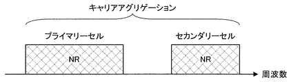
図2は、本実施形態におけるコンポーネントキャリアの設定の一例を示す図である。図2の例では、2つのNRセルが設定される。2つのNRセルは、それぞれプライマリーセルおよびセカンダリーセルとして設定され、キャリアアグリゲーションにより統合される。この場合、NRセルがスタンドアロンで通信するための機能をサポートすることにより、LTEセルのアシストが不要になる。なお、2つのNRセルは、デュアルコネクティビティにより統合されてもよい。 FIG. 2 is a diagram illustrating an example of component carrier settings in the present embodiment. In the example of FIG. 2, two NR cells are set. The two NR cells are set as a primary cell and a secondary cell, respectively, and are integrated by carrier aggregation. In this case, the support of the LTE cell becomes unnecessary by supporting the function for the NR cell to perform stand-alone communication. Note that the two NR cells may be integrated by dual connectivity.
<1.2.無線フレーム構成>
<本実施形態における無線フレーム構成>
本実施形態において、10ms(ミリ秒)で構成される無線フレーム(radio frame)が規定される。無線フレームのそれぞれは2つのハーフフレームから構成される。ハーフフレームの時間間隔は、5msである。ハーフフレームのそれぞれは、5つのサブフレームから構成される。サブフレームの時間間隔は、1msであり、2つの連続するスロットによって定義される。スロットの時間間隔は、0.5msである。無線フレーム内のi番目のサブフレームは、(2×i)番目のスロットと(2×i+1)番目のスロットとから構成される。つまり、無線フレームのそれぞれにおいて、10個のサブフレームが規定される。
<1.2. Wireless frame configuration>
<Radio frame configuration in this embodiment>
In the present embodiment, a radio frame composed of 10 ms (milliseconds) is defined. Each radio frame is composed of two half frames. The time interval of the half frame is 5 ms. Each half frame is composed of five subframes. The subframe time interval is 1 ms and is defined by two consecutive slots. The slot time interval is 0.5 ms. The i-th subframe in the radio frame is composed of a (2 × i) th slot and a (2 × i + 1) th slot. That is, 10 subframes are defined in each radio frame.
サブフレームは、下りリンクサブフレーム、上りリンクサブフレーム、スペシャルサブフレームおよびサイドリンクサブフレームなどを含む。 The subframe includes a downlink subframe, an uplink subframe, a special subframe, a sidelink subframe, and the like.
下りリンクサブフレームは下りリンク送信のために予約されるサブフレームである。上りリンクサブフレームは上りリンク送信のために予約されるサブフレームである。スペシャルサブフレームは3つのフィールドから構成される。3つのフィールドは、DwPTS(Downlink Pilot Time Slot)、GP(Guard Period)、およびUpPTS(Uplink Pilot Time Slot)を含む。DwPTS、GP、およびUpPTSの合計の長さは1msである。DwPTSは下りリンク送信のために予約されるフィールドである。UpPTSは上りリンク送信のために予約されるフィールドである。GPは下りリンク送信および上りリンク送信が行われないフィールドである。なお、スペシャルサブフレームは、DwPTSおよびGPのみによって構成されてもよいし、GPおよびUpPTSのみによって構成されてもよい。スペシャルサブフレームは、TDDにおいて下りリンクサブフレームと上りリンクサブフレームとの間に配置され、下りリンクサブフレームから上りリンクサブフレームに切り替えるために用いられる。サイドリンクサブフレームは、サイドリンク通信のために予約または設定されるサブフレームである。サイドリンクは、端末装置間の近接直接通信および近接直接検出のために用いられる。 The downlink subframe is a subframe reserved for downlink transmission. An uplink subframe is a subframe reserved for uplink transmission. The special subframe is composed of three fields. The three fields include DwPTS (Downlink Pilot Time Slot), GP (Guard Period), and UpPTS (Uplink Pilot Time Slot). The total length of DwPTS, GP, and UpPTS is 1 ms. DwPTS is a field reserved for downlink transmission. UpPTS is a field reserved for uplink transmission. GP is a field in which downlink transmission and uplink transmission are not performed. Note that the special subframe may be configured only by DwPTS and GP, or may be configured only by GP and UpPTS. The special subframe is arranged between the downlink subframe and the uplink subframe in TDD, and is used for switching from the downlink subframe to the uplink subframe. The side link subframe is a subframe reserved or set for side link communication. The side link is used for proximity direct communication and proximity direct detection between terminal devices.
単一の無線フレームは、下りリンクサブフレーム、上りリンクサブフレーム、スペシャルサブフレームおよび/またはサイドリンクサブフレームから構成される。また、単一の無線フレームは、下りリンクサブフレーム、上りリンクサブフレーム、スペシャルサブフレームまたはサイドリンクサブフレームのみで構成されてもよい。 A single radio frame is composed of a downlink subframe, an uplink subframe, a special subframe, and / or a sidelink subframe. Also, a single radio frame may be composed of only downlink subframes, uplink subframes, special subframes, or sidelink subframes.
複数の無線フレーム構成がサポートされる。無線フレーム構成は、フレーム構成タイプで規定される。フレーム構成タイプ1は、FDDのみに適用できる。フレーム構成タイプ2は、TDDのみに適用できる。フレーム構成タイプ3は、LAA(Licensed Assisted Access)セカンダリーセルの運用のみに適用できる。
Multiple radio frame configurations are supported. The radio frame configuration is defined by the frame configuration type.
フレーム構成タイプ2において、複数の上りリンク−下りリンク構成が規定される。上りリンク−下りリンク構成において、1つの無線フレームにおける10のサブフレームのそれぞれは、下りリンクサブフレーム、上りリンクサブフレーム、およびスペシャルサブフレームのいずれかに対応する。サブフレーム0、サブフレーム5およびDwPTSは常に下りリンク送信のために予約される。UpPTSおよびそのスペシャルサブフレームの直後のサブフレームは常に上りリンク送信のために予約される。
In
フレーム構成タイプ3において、1つの無線フレーム内の10のサブフレームが下りリンク送信のために予約される。端末装置2は、PDSCHまたは検出信号が送信されないサブフレームを空のサブフレームとして扱うことができる。端末装置2は、所定の信号、チャネルおよび/または下りリンク送信があるサブフレームで検出されない限り、そのサブフレームにいかなる信号および/またはチャネルも存在しないと想定する。下りリンク送信は、1つまたは複数の連続したサブフレームで専有される。その下りリンク送信の最初のサブフレームは、そのサブフレーム内のどこからでも開始されてもよい。その下りリンク送信の最後のサブフレームは、完全に専有されるか、DwPTSで規定される時間間隔で専有されるか、のいずれかであってもよい。
In
なお、フレーム構成タイプ3において、1つの無線フレーム内の10のサブフレームが上りリンク送信のために予約されてもよい。また、1つの無線フレーム内の10のサブフレームのそれぞれが、下りリンクサブフレーム、上りリンクサブフレーム、スペシャルサブフレームおよびサイドリンクサブフレームのいずれかに対応するようにしてもよい。
In
基地局装置1は、スペシャルサブフレームのDwPTSにおいて、下りリンク物理チャネルおよび下りリンク物理信号を送信してもよい。基地局装置1は、スペシャルサブフレームのDwPTSにおいて、PBCHの送信を制限できる。端末装置2は、スペシャルサブフレームのUpPTSにおいて、上りリンク物理チャネルおよび上りリンク物理信号を送信してもよい。端末装置2は、スペシャルサブフレームのUpPTSにおいて、一部の上りリンク物理チャネルおよび上りリンク物理信号の送信を制限できる。
The
なお、1つの送信における時間間隔はTTI(Transmission Time Interval)と呼称され、LTEにおいて、1ms(1サブフレーム)を1TTIと定義される。 Note that the time interval in one transmission is called TTI (Transmission Time Interval), and in LTE, 1 ms (1 subframe) is defined as 1 TTI.
<本実施形態におけるLTEのフレーム構成>
図3は、本実施形態におけるLTEの下りリンクサブフレームの一例を示す図である。図3に示される図は、LTEの下りリンクリソースグリッドとも呼称される。基地局装置1は、端末装置2への下りリンクサブフレームにおいて、LTEの下りリンク物理チャネルおよび/またはLTEの下りリンク物理信号を送信できる。端末装置2は、基地局装置1からの下りリンクサブフレームにおいて、LTEの下りリンク物理チャネルおよび/またはLTEの下りリンク物理信号を受信できる。
<LTE Frame Configuration in this Embodiment>
FIG. 3 is a diagram illustrating an example of an LTE downlink subframe in the present embodiment. The diagram shown in FIG. 3 is also referred to as an LTE downlink resource grid. The
図4は、本実施形態におけるLTEの上りリンクサブフレームの一例を示す図である。図4に示される図は、LTEの上りリンクリソースグリッドとも呼称される。端末装置2は、基地局装置1への上りリンクサブフレームにおいて、LTEの上りリンク物理チャネルおよび/またはLTEの上りリンク物理信号を送信できる。基地局装置1は、端末装置2からの上りリンクサブフレームにおいて、LTEの上りリンク物理チャネルおよび/またはLTEの上りリンク物理信号を受信できる。
FIG. 4 is a diagram illustrating an example of an LTE uplink subframe in the present embodiment. The diagram shown in FIG. 4 is also referred to as an LTE uplink resource grid. The
本実施形態において、LTEの物理リソースは以下のように定義されうる。1つのスロットは複数のシンボルによって定義される。スロットのそれぞれにおいて送信される物理信号または物理チャネルは、リソースグリッドによって表現される。下りリンクにおいて、リソースグリッドは、周波数方向に対する複数のサブキャリアと、時間方向に対する複数のOFDMシンボルによって定義される。上りリンクにおいて、リソースグリッドは、周波数方向に対する複数のサブキャリアと、時間方向に対する複数のSC−FDMAシンボルによって定義される。サブキャリアまたはリソースブロックの数は、セルの帯域幅に依存して決まるようにしてもよい。1つのスロットにおけるシンボルの数は、CP(Cyclic Prefix)のタイプによって決まる。CPのタイプは、ノーマルCPまたは拡張CPである。ノーマルCPにおいて、1つのスロットを構成するOFDMシンボルまたはSC−FDMAシンボルの数は7である。拡張CPにおいて、1つのスロットを構成するOFDMシンボルまたはSC−FDMAシンボルの数は6である。リソースグリッド内のエレメントのそれぞれはリソースエレメントと称される。リソースエレメントは、サブキャリアのインデックス(番号)とシンボルのインデックス(番号)とを用いて識別される。なお、本実施形態の説明において、OFDMシンボルまたはSC−FDMAシンボルは単にシンボルとも呼称される。 In the present embodiment, LTE physical resources can be defined as follows. One slot is defined by a plurality of symbols. The physical signal or physical channel transmitted in each of the slots is represented by a resource grid. In the downlink, the resource grid is defined by a plurality of subcarriers in the frequency direction and a plurality of OFDM symbols in the time direction. In the uplink, the resource grid is defined by a plurality of subcarriers in the frequency direction and a plurality of SC-FDMA symbols in the time direction. The number of subcarriers or resource blocks may be determined depending on the cell bandwidth. The number of symbols in one slot depends on the type of CP (Cyclic Prefix). The CP type is a normal CP or an extended CP. In the normal CP, the number of OFDM symbols or SC-FDMA symbols constituting one slot is seven. In the extended CP, the number of OFDM symbols or SC-FDMA symbols constituting one slot is six. Each element in the resource grid is called a resource element. The resource element is identified using a subcarrier index (number) and a symbol index (number). In the description of the present embodiment, the OFDM symbol or SC-FDMA symbol is also simply referred to as a symbol.
リソースブロックは、ある物理チャネル(PDSCHまたはPUSCHなど)をリソースエレメントにマッピングするために用いられる。リソースブロックは、仮想リソースブロックと物理リソースブロックを含む。ある物理チャネルは、仮想リソースブロックにマッピングされる。仮想リソースブロックは、物理リソースブロックにマッピングされる。1つの物理リソースブロックは、時間領域において所定数の連続するシンボルで定義される。1つの物理リソースブロックは、周波数領域において所定数の連続するサブキャリアとから定義される。1つの物理リソースブロックにおけるシンボル数およびサブキャリア数は、そのセルにおけるCPのタイプ、サブキャリア間隔および/または上位層によって設定されるパラメータなどに基づいて決まる。例えば、CPのタイプがノーマルCPであり、サブキャリア間隔が15kHzである場合、1つの物理リソースブロックにおけるシンボル数は7であり、サブキャリア数は12である。その場合、1つの物理リソースブロックは(7×12)個のリソースエレメントから構成される。物理リソースブロックは周波数領域において0から番号が付けられる。また、同一の物理リソースブロック番号が対応する、1つのサブフレーム内の2つのリソースブロックは、物理リソースブロックペア(PRBペア、RBペア)として定義される。 A resource block is used to map a certain physical channel (such as PDSCH or PUSCH) to a resource element. The resource block includes a virtual resource block and a physical resource block. A certain physical channel is mapped to a virtual resource block. A virtual resource block is mapped to a physical resource block. One physical resource block is defined by a predetermined number of consecutive symbols in the time domain. One physical resource block is defined from a predetermined number of consecutive subcarriers in the frequency domain. The number of symbols and the number of subcarriers in one physical resource block are determined based on the type of CP in the cell, the subcarrier spacing, and / or parameters set by higher layers. For example, when the CP type is normal CP and the subcarrier interval is 15 kHz, the number of symbols in one physical resource block is 7, and the number of subcarriers is 12. In that case, one physical resource block is composed of (7 × 12) resource elements. Physical resource blocks are numbered from 0 in the frequency domain. Further, two resource blocks in one subframe corresponding to the same physical resource block number are defined as physical resource block pairs (PRB pair, RB pair).
LTEセルのそれぞれにおいて、あるサブフレームでは、1つの所定のパラメータが用いられる。例えば、その所定のパラメータは、送信信号に関するパラメータ(物理パラメータ)である。送信信号に関するパラメータは、CP長、サブキャリア間隔、1つのサブフレーム(所定の時間長)におけるシンボル数、1つのリソースブロック(所定の周波数帯域)のおけるサブキャリア数、多元接続方式、および、信号波形などを含む。 In each LTE cell, one predetermined parameter is used in a certain subframe. For example, the predetermined parameter is a parameter (physical parameter) related to the transmission signal. Parameters related to the transmission signal include CP length, subcarrier interval, number of symbols in one subframe (predetermined time length), number of subcarriers in one resource block (predetermined frequency band), multiple access scheme, and signal Includes waveforms.
すなわち、LTEセルでは、下りリンク信号および上りリンク信号は、それぞれ所定の時間長(例えば、サブフレーム)において、1つの所定のパラメータを用いて生成される。換言すると、端末装置2は、基地局装置1から送信される下りリンク信号、および、基地局装置1に送信する上りリンク信号が、それぞれ所定の時間長において、1つの所定のパラメータで生成される、と想定する。また、基地局装置1は、端末装置2に送信する下りリンク信号、および、端末装置2から送信される上りリンク信号が、それぞれ所定の時間長において、1つの所定のパラメータで生成されるように設定する。
That is, in the LTE cell, the downlink signal and the uplink signal are generated using one predetermined parameter in each predetermined time length (for example, subframe). In other words, the
<本実施形態におけるNRのフレーム構成>
NRセルのそれぞれにおいて、ある所定の時間長(例えば、サブフレーム)では、1つ以上の所定のパラメータが用いられる。すなわち、NRセルでは、下りリンク信号および上りリンク信号は、それぞれ所定の時間長において、1つ以上の所定のパラメータを用いて生成される。換言すると、端末装置2は、基地局装置1から送信される下りリンク信号、および、基地局装置1に送信する上りリンク信号が、それぞれ所定の時間長において、1つ以上の所定のパラメータで生成される、と想定する。また、基地局装置1は、端末装置2に送信する下りリンク信号、および、端末装置2から送信される上りリンク信号が、それぞれ所定の時間長において、1つ以上の所定のパラメータで生成されるように設定できる。複数の所定のパラメータが用いられる場合、それらの所定のパラメータが用いられて生成される信号は、所定の方法により多重される。例えば、所定の方法は、FDM(Frequency Division Multiplexing)、TDM(Time Division Multiplexing)、CDM(Code Division Multiplexing)および/またはSDM(Spatial Division Multiplexing)などを含む。
<Frame structure of NR in this embodiment>
In each of the NR cells, one or more predetermined parameters are used in a certain predetermined time length (for example, subframe). That is, in the NR cell, the downlink signal and the uplink signal are each generated with one or more predetermined parameters in a predetermined time length. In other words, the
NRセルに設定される所定のパラメータの組み合わせは、パラメータセットとして、複数種類を予め規定できる。 A plurality of types of combinations of predetermined parameters set in the NR cell can be defined in advance as a parameter set.
図5は、NRセルにおける送信信号に関するパラメータセットの一例を示す図である。図5の例では、パラメータセットに含まれる送信信号に関するパラメータは、サブキャリア間隔、NRセルにおけるリソースブロックあたりのサブキャリア数、サブフレームあたりのシンボル数、および、CP長タイプである。CP長タイプは、NRセルで用いられるCP長のタイプである。例えば、CP長タイプ1はLTEにおけるノーマルCPに相当し、CP長タイプ2はLTEにおける拡張CPに相当する。
FIG. 5 is a diagram illustrating an example of a parameter set regarding a transmission signal in the NR cell. In the example of FIG. 5, the parameters related to the transmission signal included in the parameter set are the subcarrier interval, the number of subcarriers per resource block in the NR cell, the number of symbols per subframe, and the CP length type. The CP length type is a CP length type used in the NR cell. For example,
NRセルにおける送信信号に関するパラメータセットは、下りリンクおよび上りリンクでそれぞれ個別に規定することができる。また、NRセルにおける送信信号に関するパラメータセットは、下りリンクおよび上りリンクでそれぞれ独立に設定できる。 Parameter sets related to transmission signals in the NR cell can be individually defined in the downlink and uplink. Also, parameter sets related to transmission signals in the NR cell can be set independently for the downlink and uplink.
図6は、本実施形態におけるNRの下りリンクサブフレームの一例を示す図である。図6の例では、パラメータセット1、パラメータセット0およびパラメータセット2を用いて生成される信号が、セル(システム帯域幅)において、FDMされる。図6に示される図は、NRの下りリンクリソースグリッドとも呼称される。基地局装置1は、端末装置2への下りリンクサブフレームにおいて、NRの下りリンク物理チャネルおよび/またはNRの下りリンク物理信号を送信できる。端末装置2は、基地局装置1からの下りリンクサブフレームにおいて、NRの下りリンク物理チャネルおよび/またはNRの下りリンク物理信号を受信できる。
FIG. 6 is a diagram illustrating an example of an NR downlink subframe in the present embodiment. In the example of FIG. 6, a signal generated using the parameter set 1, the parameter set 0, and the parameter set 2 is FDM in the cell (system bandwidth). The diagram shown in FIG. 6 is also referred to as the NR downlink resource grid. The
図7は、本実施形態におけるNRの上りリンクサブフレームの一例を示す図である。図7の例では、パラメータセット1、パラメータセット0およびパラメータセット2を用いて生成される信号が、セル(システム帯域幅)において、FDMされる。図6に示される図は、NRの上りリンクリソースグリッドとも呼称される。基地局装置1は、端末装置2への上りリンクサブフレームにおいて、NRの上りリンク物理チャネルおよび/またはNRの上りリンク物理信号を送信できる。端末装置2は、基地局装置1からの上りリンクサブフレームにおいて、NRの上りリンク物理チャネルおよび/またはNRの上りリンク物理信号を受信できる。
FIG. 7 is a diagram illustrating an example of an uplink subframe of NR in the present embodiment. In the example of FIG. 7, a signal generated using parameter set 1, parameter set 0, and parameter set 2 is FDM in a cell (system bandwidth). The diagram shown in FIG. 6 is also referred to as the NR uplink resource grid. The
<本実施形態におけるアンテナポート>
アンテナポートは、あるシンボルを運ぶ伝搬チャネルが、同一のアンテナポートにおける別のシンボルを運ぶ伝搬チャネルから推測できるようにするために定義される。例えば、同一のアンテナポートにおける異なる物理リソースは、同一の伝搬チャネルで送信されていると想定できる。すなわち、あるアンテナポートにおけるシンボルは、そのアンテナポートにおける参照信号により伝搬チャネルを推定し、復調することができる。また、アンテナポート毎に1つのリソースグリッドがある。アンテナポートは、参照信号によって定義される。また、それぞれの参照信号は、複数のアンテナポートを定義できる。
アンテナポートはアンテナポート番号によって特定または識別される。例えば、アンテナポート0〜3は、CRSが送信されるアンテナポートである。すなわち、アンテナポート0〜3で送信されるPDSCHは、アンテナポート0〜3に対応するCRSで復調できる。
<Antenna port in this embodiment>
An antenna port is defined so that a propagation channel carrying one symbol can be inferred from a propagation channel carrying another symbol at the same antenna port. For example, it can be assumed that different physical resources in the same antenna port are transmitted on the same propagation channel. In other words, a symbol at a certain antenna port can be demodulated by estimating a propagation channel using a reference signal at that antenna port. There is one resource grid per antenna port. An antenna port is defined by a reference signal. Each reference signal can define a plurality of antenna ports.
An antenna port is identified or identified by an antenna port number. For example,
2つのアンテナポートは所定の条件を満たす場合、準同一位置(QCL:Quasi co-location)であると表すことができる。その所定の条件は、あるアンテナポートにおけるシンボルを運ぶ伝搬チャネルの広域的特性が、別のアンテナポートにおけるシンボルを運ぶ伝搬チャネルから推測できることである。広域的特性は、遅延分散、ドップラースプレッド、ドップラーシフト、平均利得および/または平均遅延を含む。 When the two antenna ports satisfy a predetermined condition, they can be expressed as quasi-co-location (QCL). The predetermined condition is that the wide-area characteristics of a propagation channel carrying a symbol at one antenna port can be inferred from the propagation channel carrying a symbol at another antenna port. Global characteristics include delay dispersion, Doppler spread, Doppler shift, average gain and / or average delay.
本実施形態において、アンテナポート番号は、RAT毎に異なって定義されてもよいし、RAT間で共通に定義されてもよい。例えば、LTEにおけるアンテナポート0〜3は、CRSが送信されるアンテナポートである。NRにおいて、アンテナポート0〜3は、LTEと同様のCRSが送信されるアンテナポートとすることができる。また、NRにおいて、LTEと同様のCRSが送信されるアンテナポートは、アンテナポート0〜3とは異なるアンテナポート番号とすることができる。本実施形態の説明において、所定のアンテナポート番号は、LTEおよび/またはNRに対して適用できる。
In the present embodiment, the antenna port number may be defined differently for each RAT, or may be defined in common between RATs. For example,
<1.3.チャネルおよび信号>
<本実施形態における物理チャネルおよび物理信号>
本実施形態において、物理チャネルおよび物理信号が用いられる。
物理チャネルは、下りリンク物理チャネル、上りリンク物理チャネルおよびサイドリンク物理チャネルを含む。物理信号は、下りリンク物理信号、上りリンク物理信号およびサイドリンク物理信号を含む。
LTEにおける物理チャネルおよび物理信号は、それぞれLTE物理チャネルおよびLTE物理信号とも呼称される。NRにおける物理チャネルおよび物理信号は、それぞれNR物理チャネルおよびNR物理信号とも呼称される。LTE物理チャネルおよびNR物理チャネルは、それぞれ異なる物理チャネルとして定義できる。LTE物理信号およびNR物理信号は、それぞれ異なる物理信号として定義できる。本実施形態の説明において、LTE物理チャネルおよびNR物理チャネルは単に物理チャネルとも呼称され、LTE物理信号およびNR物理信号は単に物理信号とも呼称される。すなわち、物理チャネルに対する説明は、LTE物理チャネルおよびNR物理チャネルのいずれに対しても適用できる。物理信号に対する説明は、LTE物理信号およびNR物理信号のいずれに対しても適用できる。
<1.3. Channels and signals>
<Physical channel and physical signal in this embodiment>
In this embodiment, physical channels and physical signals are used.
The physical channel includes a downlink physical channel, an uplink physical channel, and a side link physical channel. The physical signal includes a downlink physical signal, an uplink physical signal, and a side link physical signal.
Physical channels and physical signals in LTE are also referred to as LTE physical channels and LTE physical signals, respectively. The physical channel and physical signal in NR are also referred to as NR physical channel and NR physical signal, respectively. The LTE physical channel and the NR physical channel can be defined as different physical channels. The LTE physical signal and the NR physical signal can be defined as different physical signals. In the description of this embodiment, the LTE physical channel and the NR physical channel are also simply referred to as physical channels, and the LTE physical signal and the NR physical signal are also simply referred to as physical signals. That is, the description for the physical channel can be applied to both the LTE physical channel and the NR physical channel. The description for the physical signal can be applied to both the LTE physical signal and the NR physical signal.
<本実施形態におけるNR物理チャネルおよびNR物理信号>
LTEにおける物理チャネルおよび物理信号に対する説明は、それぞれNR物理チャネルおよびNR物理信号に対しても適用できる。NR物理チャネルおよびNR物理信号は、以下のように呼称される。
<NR physical channel and NR physical signal in this embodiment>
The description for the physical channel and the physical signal in LTE can be applied to the NR physical channel and the NR physical signal, respectively. The NR physical channel and the NR physical signal are referred to as follows.
NR下りリンク物理チャネルは、NR−PBCH、NR−PCFICH、NR−PHICH、NR−PDCCH、NR−EPDCCH、NR−MPDCCH、NR−R−PDCCH、NR−PDSCH、および、NR−PMCHなどを含む。 The NR downlink physical channel includes NR-PBCH, NR-PCFICH, NR-PHICH, NR-PDCCH, NR-EPDCCH, NR-MPDCCH, NR-R-PDCCH, NR-PDSCH, NR-PMCH, and the like.
NR下りリンク物理信号は、NR−SS、NR−DL−RSおよびNR−DSなどを含む。NR−SSは、NR−PSSおよびNR−SSSなどを含む。NR−RSは、NR−CRS、NR−PDSCH−DMRS、NR−EPDCCH−DMRS、NR−PRS、NR−CSI−RS、およびNR−TRSなどを含む。 The NR downlink physical signal includes NR-SS, NR-DL-RS, NR-DS, and the like. NR-SS includes NR-PSS, NR-SSS, and the like. NR-RS includes NR-CRS, NR-PDSCH-DMRS, NR-EPDCCH-DMRS, NR-PRS, NR-CSI-RS, NR-TRS, and the like.
NR上りリンク物理チャネルは、NR−PUSCH、NR−PUCCH、およびNR−PRACHなどを含む。 The NR uplink physical channel includes NR-PUSCH, NR-PUCCH, NR-PRACH, and the like.
NR上りリンク物理信号は、NR−UL−RSを含む。NR−UL−RSは、NR−UL−DMRSおよびNR−SRSなどを含む。 The NR uplink physical signal includes NR-UL-RS. NR-UL-RS includes NR-UL-DMRS and NR-SRS.
NRサイドリンク物理チャネルは、NR−PSBCH、NR−PSCCH、NR−PSDCH、およびNR−PSSCHなどを含む。 The NR side link physical channel includes NR-PSBCH, NR-PSCCH, NR-PSDCH, NR-PSSCH, and the like.
<本実施形態における下りリンク物理チャネル>
PBCHは、基地局装置1のサービングセルに固有の報知情報であるMIB(Master Information Block)を報知するために用いられる。PBCHは無線フレーム内のサブフレーム0のみで送信される。MIBは、40ms間隔で更新できる。PBCHは10ms周期で繰り返し送信される。具体的には、SFN(System Frame Number)を4で割った余りが0である条件を満たす無線フレームにおけるサブフレーム0においてMIBの初期送信が行なわれ、他の全ての無線フレームにおけるサブフレーム0においてMIBの再送信(repetition)が行われる。SFNは無線フレームの番号(システムフレーム番号)である。MIBはシステム情報である。例えば、MIBは、SFNを示す情報を含む。
PCFICHは、PDCCHの送信に用いられるOFDMシンボルの数に関する情報を送信するために用いられる。PCFICHで示される領域は、PDCCH領域とも呼称される。PCFICHで送信される情報は、CFI(Control Format Indicator)とも呼称される。
<Downlink physical channel in this embodiment>
The PBCH is used to broadcast an MIB (Master Information Block) that is broadcast information unique to the serving cell of the
PCFICH is used to transmit information regarding the number of OFDM symbols used for transmission of PDCCH. A region indicated by PCFICH is also referred to as a PDCCH region. Information transmitted by PCFICH is also referred to as CFI (Control Format Indicator).
PHICHは、基地局装置1が受信した上りリンクデータ(Uplink Shared Channel: UL-SCH)に対するACK(ACKnowledgement)またはNACK(Negative ACKnowledgement)を示すHARQ−ACK(HARQインディケータ、HARQフィードバック、応答情報)を送信するために用いられる。例えば、端末装置2がACKを示すHARQ−ACKを受信した場合は、対応する上りリンクデータを再送しない。例えば、端末装置2がNACKを示すHARQ−ACKを受信した場合は、端末装置2は対応する上りリンクデータを所定の上りリンクサブフレームで再送する。あるPHICHは、ある上りリンクデータに対するHARQ−ACKを送信する。基地局装置1は、同一のPUSCHに含まれる複数の上りリンクデータに対するHARQ−ACKのそれぞれを複数のPHICHを用いて送信する。
The PHICH transmits HARQ-ACK (HARQ indicator, HARQ feedback, response information) indicating ACK (ACKnowledgement) or NACK (Negative ACKnowledgement) for uplink data (Uplink Shared Channel: UL-SCH) received by the
PDCCHおよびEPDCCHは、下りリンク制御情報(Downlink Control Information: DCI)を送信するために用いられる。下りリンク制御情報の情報ビットのマッピングが、DCIフォーマットとして定義される。下りリンク制御情報は、下りリンクグラント(downlink grant)および上りリンクグラント(uplink grant)を含む。下りリンクグラントは、下りリンクアサインメント(downlink assignment)または下りリンク割り当て(downlink allocation)とも称する。 PDCCH and EPDCCH are used for transmitting downlink control information (Downlink Control Information: DCI). Mapping of information bits of downlink control information is defined as a DCI format. The downlink control information includes a downlink grant (downlink grant) and an uplink grant (uplink grant). The downlink grant is also referred to as downlink assignment or downlink allocation.
PDCCHは、連続する1つまたは複数のCCE(Control Channel Element)の集合によって送信される。CCEは、9つのREG(Resource Element Group)で構成される。REGは、4つのリソースエレメントで構成される。PDCCHがn個の連続するCCEで構成される場合、そのPDCCHは、CCEのインデックス(番号)であるiをnで割った余りが0である条件を満たすCCEから始まる。 The PDCCH is transmitted by a set of one or more consecutive CCEs (Control Channel Elements). The CCE is composed of nine REGs (Resource Element Groups). The REG is composed of four resource elements. When the PDCCH is composed of n consecutive CCEs, the PDCCH starts with a CCE that satisfies the condition that a remainder obtained by dividing i, which is an index (number) of the CCE, by n is 0.
EPDCCHは、連続する1つまたは複数のECCE(Enhanced Control Channel Element)の集合によって送信される。ECCEは、複数のEREG(Enhanced Resource Element Group)で構成される。 The EPDCCH is transmitted by a set of one or a plurality of continuous enhanced control channel elements (ECCEs). The ECCE is composed of a plurality of EREG (Enhanced Resource Element Group).
下りリンクグラントは、あるセル内のPDSCHのスケジューリングに用いられる。下りリンクグラントは、その下りリンクグラントが送信されたサブフレームと同じサブフレーム内のPDSCHのスケジューリングに用いられる。上りリンクグラントは、あるセル内のPUSCHのスケジューリングに用いられる。上りリンクグラントは、その上りリンクグラントが送信されたサブフレームより4つ以上後のサブフレーム内の単一のPUSCHのスケジューリングに用いられる。 The downlink grant is used for scheduling of PDSCH in a certain cell. The downlink grant is used for scheduling the PDSCH in the same subframe as the subframe in which the downlink grant is transmitted. The uplink grant is used for scheduling the PUSCH in a certain cell. The uplink grant is used for scheduling a single PUSCH in a subframe that is four or more times after the subframe in which the uplink grant is transmitted.
DCIには、CRC(Cyclic Redundancy Check)パリティビットが付加される。CRCパリティビットは、RNTI(Radio Network Temporary Identifier)でスクランブルされる。RNTIは、DCIの目的などに応じて、規定または設定できる識別子である。RNTIは、仕様で予め規定される識別子、セルに固有の情報として設定される識別子、端末装置2に固有の情報として設定される識別子、または、端末装置2に属するグループに固有の情報として設定される識別子である。例えば、端末装置2は、PDCCHまたはEPDCCHのモニタリングにおいて、DCIに付加されたCRCパリティビットに所定のRNTIでデスクランブルし、CRCが正しいかどうかを識別する。CRCが正しい場合、そのDCIは端末装置2のためのDCIであることが分かる。
A CRC (Cyclic Redundancy Check) parity bit is added to the DCI. The CRC parity bit is scrambled with an RNTI (Radio Network Temporary Identifier). The RNTI is an identifier that can be defined or set according to the purpose of the DCI. The RNTI is set as an identifier preliminarily specified in the specification, an identifier set as information specific to a cell, an identifier set as information specific to the
PDSCHは、下りリンクデータ(Downlink Shared Channel: DL-SCH)を送信するために用いられる。また、PDSCHは、上位層の制御情報を送信するためにも用いられる。 The PDSCH is used to transmit downlink data (Downlink Shared Channel: DL-SCH). The PDSCH is also used for transmitting higher layer control information.
PMCHは、マルチキャストデータ(Multicast Channel: MCH)を送信するために用いられる。 The PMCH is used for transmitting multicast data (Multicast Channel: MCH).
PDCCH領域において、複数のPDCCHが周波数、時間、および/または、空間多重されてもよい。EPDCCH領域において、複数のEPDCCHが周波数、時間、および/または、空間多重されてもよい。PDSCH領域において、複数のPDSCHが周波数、時間、および/または、空間多重されてもよい。PDCCH、PDSCHおよび/またはEPDCCHは周波数、時間、および/または、空間多重されてもよい。 In the PDCCH region, a plurality of PDCCHs may be frequency, time, and / or spatially multiplexed. In the EPDCCH region, a plurality of EPDCCHs may be frequency, time and / or spatially multiplexed. In the PDSCH region, a plurality of PDSCHs may be frequency, time and / or spatially multiplexed. PDCCH, PDSCH and / or EPDCCH may be frequency, time and / or spatially multiplexed.
<本実施形態における下りリンク物理信号>
同期信号は、端末装置2が下りリンクの周波数領域および/または時間領域の同期をとるために用いられる。同期信号は、PSS(Primary Synchronization Signal)およびSSS(Secondary Synchronization Signal)を含む。同期信号は無線フレーム内の所定のサブフレームに配置される。例えば、TDD方式において、同期信号は無線フレーム内のサブフレーム0、1、5、および6に配置される。FDD方式において、同期信号は無線フレーム内のサブフレーム0および5に配置される。
<Downlink physical signal in this embodiment>
The synchronization signal is used for the
PSSは、粗いフレーム/シンボルタイミング同期(時間領域の同期)やセル識別グループの識別に用いられてもよい。SSSは、より正確なフレームタイミング同期やセルの識別、CP長の検出に用いられてもよい。つまり、PSSとSSSを用いることによって、フレームタイミング同期とセル識別を行うことができる。 The PSS may be used for coarse frame / symbol timing synchronization (time domain synchronization) and cell identification group identification. The SSS may be used for more accurate frame timing synchronization, cell identification, and CP length detection. That is, frame timing synchronization and cell identification can be performed by using PSS and SSS.
下りリンク参照信号は、端末装置2が下りリンク物理チャネルの伝搬路推定、伝搬路補正、下りリンクのCSI(Channel State Information、チャネル状態情報)の算出、および/または、端末装置2のポジショニングの測定を行うために用いられる。
For the downlink reference signal, the
CRSは、サブフレームの全帯域で送信される。CRSは、PBCH、PDCCH、PHICH、PCFICH、およびPDSCHの受信(復調)を行うために用いられる。CRSは、端末装置2が下りリンクのチャネル状態情報を算出するために用いられてもよい。PBCH、PDCCH、PHICH、およびPCFICHは、CRSの送信に用いられるアンテナポートで送信される。CRSは、1、2または4のアンテナポートの構成をサポートする。CRSは、アンテナポート0〜3の1つまたは複数で送信される。
The CRS is transmitted in the entire band of the subframe. CRS is used to receive (demodulate) PBCH, PDCCH, PHICH, PCFICH, and PDSCH. The CRS may be used for the
PDSCHに関連するURSは、URSが関連するPDSCHの送信に用いられるサブフレームおよび帯域で送信される。URSは、URSが関連するPDSCHの復調を行なうために用いられる。PDSCHに関連するURSは、アンテナポート5、7〜14の1つまたは複数で送信される。
The URS associated with the PDSCH is transmitted in subframes and bands used for transmission of the PDSCH associated with the URS. URS is used to demodulate the PDSCH with which the URS is associated. The URS associated with the PDSCH is transmitted on one or more of the
PDSCHは、送信モードおよびDCIフォーマットに基づいて、CRSまたはURSの送信に用いられるアンテナポートで送信される。DCIフォーマット1Aは、CRSの送信に用いられるアンテナポートで送信されるPDSCHのスケジューリングに用いられる。DCIフォーマット2Dは、URSの送信に用いられるアンテナポートで送信されるPDSCHのスケジューリングに用いられる。 The PDSCH is transmitted through an antenna port used for CRS or URS transmission based on the transmission mode and the DCI format. The DCI format 1A is used for scheduling of PDSCH transmitted through an antenna port used for CRS transmission. The DCI format 2D is used for scheduling of the PDSCH transmitted through the antenna port used for URS transmission.
EPDCCHに関連するDMRSは、DMRSが関連するEPDCCHの送信に用いられるサブフレームおよび帯域で送信される。DMRSは、DMRSが関連するEPDCCHの復調を行なうために用いられる。EPDCCHは、DMRSの送信に用いられるアンテナポートで送信される。EPDCCHに関連するDMRSは、アンテナポート107〜114の1つまたは複数で送信される。 The DMRS associated with the EPDCCH is transmitted in subframes and bands used for transmission of the EPDCCH associated with the DMRS. DMRS is used to demodulate the EPDCCH with which DMRS is associated. The EPDCCH is transmitted through an antenna port used for DMRS transmission. The DMRS associated with the EPDCCH is transmitted on one or more of the antenna ports 107-114.
CSI−RSは、設定されたサブフレームで送信される。CSI−RSが送信されるリソースは、基地局装置1によって設定される。CSI−RSは、端末装置2が下りリンクのチャネル状態情報を算出するために用いられる。端末装置2は、CSI−RSを用いて信号測定(チャネル測定)を行う。CSI−RSは、1、2、4、8、12、16、24および32の一部または全部のアンテナポートの設定をサポートする。CSI−RSは、アンテナポート15〜46の1つまたは複数で送信される。なお、サポートされるアンテナポートは、端末装置2の端末装置ケイパビリティ、RRCパラメータの設定、および/または設定される送信モードなどに基づいて決定されてもよい。
CSI-RS is transmitted in the set subframe. A resource for transmitting the CSI-RS is set by the
ZP CSI−RSのリソースは、上位層によって設定される。ZP CSI−RSのリソースはゼロ出力の電力で送信されてもよい。すなわち、ZP CSI−RSのリソースは何も送信しなくてもよい。ZP CSI−RSの設定したリソースにおいて、PDSCHおよびEPDCCHは送信されない。例えば、ZP CSI−RSのリソースは隣接セルがNZP CSI−RSの送信を行うために用いられる。また、例えば、ZP CSI−RSのリソースはCSI−IMを測定するために用いられる。また、例えば、ZP CSI−RSのリソースはPDSCHなどの所定のチャネルが送信されないリソースである。換言すると、所定のチャネルは、ZP CSI−RSのリソースを除いて(レートマッチングして、パンクチャして)マッピングされる。なお、本実施形態では、ZP CSI−RSと明記してなければ、CSI−RSは非ゼロ電力(NZP)CSI−RSとみなす。 ZP CSI-RS resources are set by higher layers. ZP CSI-RS resources may be transmitted with zero output power. That is, no ZP CSI-RS resource need be transmitted. PDSCH and EPDCCH are not transmitted in the resource set by ZP CSI-RS. For example, ZP CSI-RS resources are used by neighboring cells to transmit NZP CSI-RS. Also, for example, ZP CSI-RS resources are used to measure CSI-IM. Further, for example, the resource of ZP CSI-RS is a resource that does not transmit a predetermined channel such as PDSCH. In other words, a predetermined channel is mapped by excluding ZP CSI-RS resources (rate matching and puncturing). In the present embodiment, the CSI-RS is regarded as a non-zero power (NZP) CSI-RS unless explicitly described as ZP CSI-RS.
DS(Discovery Signal、発見信号)は、端末装置がセルを発見し、RRM測定を行うなどの目的で送信される。DSは、フレーム構成タイプ1(FDD)において1つから5つの連続したサブフレーム、フレーム構成タイプ2(TDD)において2つから5つの連続したサブフレーム、フレーム構成タイプ3(LAA)において1つの空ではない(いずれかの信号が送信される)サブフレームを対象として、当該サブフレーム内における12個の連続したOFDMシンボルにより構成される。DSは、アンテナポート0で送信されるCRS、PSS、SSS、および、0個以上の非ゼロ電力CSI−RSで構成される。端末装置は、DMTC(discovery measurement timing configuration)が専用(dedicated)RRCによって設定される。DMTCでは、周期とオフセットとDMTC区間が設定される。DS内のCRSは、DS区間内の全ての下りリンクサブフレームとDwPTSに含まれる。DS内のPSSは、フレーム構成タイプ1(FDD)とフレーム構成タイプ3(LAA)においてDS区間内の先頭のサブフレームに含まれる。また、DS内のPSSは、フレーム構成タイプ2(TDD)においてDS区間内の2番目のサブフレームに含まれる。DS内のSSSは、DS区間内の先頭のサブフレームに含まれる。DS内の非ゼロ電力CSI−RSは上位層から設定されたSSSからのオフセット情報に基づいたサブフレームに含まれる。
DS (Discovery Signal) is transmitted for the purpose of a terminal device discovering a cell and performing RRM measurement. DS is one to five consecutive subframes in frame configuration type 1 (FDD), two to five consecutive subframes in frame configuration type 2 (TDD), and one empty in frame configuration type 3 (LAA). For a subframe that is not (a signal is transmitted), it is composed of 12 consecutive OFDM symbols in the subframe. The DS is composed of CRS, PSS, SSS, and zero or more non-zero power CSI-RSs transmitted at
<本実施形態における上りリンク物理チャネル>
PUCCHは、上りリンク制御情報(Uplink Control Information: UCI)を送信するために用いられる物理チャネルである。上りリンク制御情報は、下りリンクのチャネル状態情報(Channel State Information: CSI)、PUSCHリソースの要求を示すスケジューリング要求(Scheduling Request: SR)、下りリンクデータ(Transport block: TB, Downlink-Shared Channel: DL-SCH)に対するHARQ−ACKを含む。HARQ−ACKは、ACK/NACK、HARQフィードバック、または、応答情報とも称される。また、下りリンクデータに対するHARQ−ACKは、ACK、NACK、またはDTXを示す。
<Uplink physical channel in this embodiment>
The PUCCH is a physical channel used for transmitting uplink control information (UPCI). The uplink control information includes downlink channel state information (CSI), scheduling request (SR) indicating a request for PUSCH resources, downlink data (Transport block: TB, Downlink-Shared Channel: DL). -SCH) for HARQ-ACK. HARQ-ACK is also referred to as ACK / NACK, HARQ feedback, or response information. In addition, HARQ-ACK for downlink data indicates ACK, NACK, or DTX.
PUSCHは、上りリンクデータ(Uplink-Shared Channel: UL-SCH)を送信するために用いられる物理チャネルである。また、PUSCHは、上りリンクデータと共にHARQ−ACKおよび/またはチャネル状態情報を送信するために用いられてもよい。また、PUSCHは、チャネル状態情報のみ、または、HARQ−ACKおよびチャネル状態情報のみを送信するために用いられてもよい。 The PUSCH is a physical channel used for transmitting uplink data (Uplink-Shared Channel: UL-SCH). The PUSCH may also be used to transmit HARQ-ACK and / or channel state information along with uplink data. Moreover, PUSCH may be used to transmit only channel state information, or only HARQ-ACK and channel state information.
PRACHは、ランダムアクセスプリアンブルを送信するために用いられる物理チャネルである。PRACHは、端末装置2が基地局装置1と時間領域の同期をとるために用いられることができる。また、PRACHは、初期コネクション構築(initial connection establishment)手続き(処理)、ハンドオーバ手続き、コネクション再構築(connection re-establishment)手続き、上りリンク送信に対する同期(タイミング調整)、および/または、PUSCHリソースの要求を示すためにも用いられる。
PRACH is a physical channel used for transmitting a random access preamble. The PRACH can be used for the
PUCCH領域において、複数のPUCCHが周波数、時間、空間および/またはコード多重される。PUSCH領域において、複数のPUSCHが周波数、時間、空間および/またはコード多重されてもよい。PUCCHおよびPUSCHは周波数、時間、空間および/またはコード多重されてもよい。PRACHは単一のサブフレームまたは2つのサブフレームにわたって配置されてもよい。複数のPRACHが符号多重されてもよい。 In the PUCCH region, a plurality of PUCCHs are frequency, time, space and / or code multiplexed. In the PUSCH region, a plurality of PUSCHs may be frequency, time, space and / or code multiplexed. PUCCH and PUSCH may be frequency, time, space and / or code multiplexed. The PRACH may be arranged over a single subframe or two subframes. A plurality of PRACHs may be code-multiplexed.
<本実施形態における制御チャネルのための物理リソース>
リソースエレメントグループ(REG:Resource Element Group)は、リソースエレメントと制御チャネルのマッピングを定義するために用いられる。例えば、REGは、PDCCH、PHICH、またはPCFICHのマッピングに用いられる。REGは、同一のOFDMシンボル内であり、同一のリソースブロック内において、CRSのために用いられない4つの連続したリソースエレメントで構成される。また、REGは、あるサブフレーム内の1番目のスロットにおける1番目のOFDMシンボルから4番目のOFDMシンボルの中で構成される。
<Physical resource for control channel in this embodiment>
A resource element group (REG) is used to define a mapping between resource elements and control channels. For example, REG is used for mapping of PDCCH, PHICH, or PCFICH. The REG is composed of four consecutive resource elements that are not used for CRS in the same OFDM symbol and in the same resource block. The REG is configured from the first OFDM symbol to the fourth OFDM symbol in the first slot in a certain subframe.
拡張リソースエレメントグループ(EREG:Enhanced Resource Element Group)は、リソースエレメントと拡張制御チャネルのマッピングを定義するために用いられる。例えば、EREGは、EPDCCHのマッピングに用いられる。1つのリソースブロックペアは16のEREGで構成される。それぞれのEREGはリソースブロックペア毎に0から15の番号が付される。それぞれのEREGは、1つのリソースブロックペアにおいて、EPDCCHに関連付けられたDM−RSのために用いられるリソースエレメントを除いた9つのリソースエレメントで構成される。 An enhanced resource element group (EREG) is used to define the mapping between resource elements and enhanced control channels. For example, EREG is used for EPDCCH mapping. One resource block pair is composed of 16 EREGs. Each EREG is assigned a number from 0 to 15 for each resource block pair. Each EREG is composed of nine resource elements excluding resource elements used for DM-RS associated with EPDCCH in one resource block pair.
<1.4.構成>
<本実施形態における基地局装置1の構成例>
図8は、本実施形態の基地局装置1の構成を示す概略ブロック図である。図示するように、基地局装置1は、上位層処理部101、制御部103、受信部105、送信部107、および、送受信アンテナ109、を含んで構成される。また、受信部105は、復号化部1051、復調部1053、多重分離部1055、無線受信部1057、およびチャネル測定部1059を含んで構成される。また、送信部107は、符号化部1071、変調部1073、多重部1075、無線送信部1077、および下りリンク参照信号生成部1079を含んで構成される。
<1.4. Configuration>
<Configuration example of
FIG. 8 is a schematic block diagram illustrating the configuration of the
既に説明したように、基地局装置1は、1つ以上のRATをサポートできる。図8に示す基地局装置1に含まれる各部の一部または全部は、RATに応じて個別に構成されうる。例えば、受信部105および送信部107は、LTEとNRとで個別に構成される。また、NRセルにおいて、図8に示す基地局装置1に含まれる各部の一部または全部は、送信信号に関するパラメータセットに応じて個別に構成されうる。例えば、あるNRセルにおいて、無線受信部1057および無線送信部1077は、送信信号に関するパラメータセットに応じて個別に構成されうる。
As already described, the
上位層処理部101は、媒体アクセス制御(MAC: Medium Access Control)層、パケットデータ統合プロトコル(Packet Data Convergence Protocol: PDCP)層、無線リンク制御(Radio Link Control: RLC)層、無線リソース制御(Radio Resource Control: RRC)層の処理を行う。また、上位層処理部101は、受信部105、および送信部107の制御を行うために制御情報を生成し、制御部103に出力する。
The upper
制御部103は、上位層処理部101からの制御情報に基づいて、受信部105および送信部107の制御を行う。制御部103は、上位層処理部101への制御情報を生成し、上位層処理部101に出力する。制御部103は、復号化部1051からの復号化された信号およびチャネル測定部1059からのチャネル推定結果を入力する。制御部103は、符号化する信号を符号化部1071へ出力する。また、制御部103は、基地局装置1の全体または一部を制御するために用いられる。
The
上位層処理部101は、RAT制御、無線リソース制御、サブフレーム設定、スケジューリング制御、および/または、CSI報告制御に関する処理および管理を行う。上位層処理部101における処理および管理は、端末装置毎、または基地局装置に接続している端末装置共通に行われる。上位層処理部101における処理および管理は、上位層処理部101のみで行われてもよいし、上位ノードまたは他の基地局装置から取得してもよい。また、上位層処理部101における処理および管理は、RATに応じて個別に行われてもよい。例えば、上位層処理部101は、LTEにおける処理および管理と、NRにおける処理および管理とを個別に行う。
The upper
上位層処理部101におけるRAT制御では、RATに関する管理が行われる。例えば、RAT制御では、LTEに関する管理および/またはNRに関する管理が行われる。NRに関する管理は、NRセルにおける送信信号に関するパラメータセットの設定および処理を含む。
In the RAT control in the upper
上位層処理部101における無線リソース制御では、下りリンクデータ(トランスポートブロック)、システムインフォメーション、RRCメッセージ(RRCパラメータ)、および/または、MAC制御エレメント(CE:Control Element)の生成および/または管理が行われる。
In radio resource control in the higher
上位層処理部101におけるサブフレーム設定では、サブフレーム設定、サブフレームパターン設定、上りリンク−下りリンク設定、上りリンク参照UL−DL設定、および/または、下りリンク参照UL−DL設定の管理が行われる。なお、上位層処理部101におけるサブフレーム設定は、基地局サブフレーム設定とも呼称される。また、上位層処理部101におけるサブフレーム設定は、上りリンクのトラフィック量および下りリンクのトラフィック量に基づいて決定できる。また、上位層処理部101におけるサブフレーム設定は、上位層処理部101におけるスケジューリング制御のスケジューリング結果に基づいて決定できる。
In the subframe setting in the higher
上位層処理部101におけるスケジューリング制御では、受信したチャネル状態情報およびチャネル測定部1059から入力された伝搬路の推定値やチャネルの品質などに基づいて、物理チャネルを割り当てる周波数およびサブフレーム、物理チャネルの符号化率および変調方式および送信電力などが決定される。例えば、制御部103は、上位層処理部101におけるスケジューリング制御のスケジューリング結果に基づいて、制御情報(DCIフォーマット)を生成する。
In the scheduling control in the upper
上位層処理部101におけるCSI報告制御では、端末装置2のCSI報告が制御される。例えば、端末装置2においてCSIを算出するために想定するためのCSI参照リソースに関する設定が制御される。
In the CSI report control in the upper
受信部105は、制御部103からの制御に従って、送受信アンテナ109を介して端末装置2から送信された信号を受信し、さらに分離、復調、復号などの受信処理を行い、受信処理された情報を制御部103に出力する。なお、受信部105における受信処理は、あらかじめ規定された設定、または基地局装置1が端末装置2に通知した設定に基づいて行われる。
The receiving
無線受信部1057は、送受信アンテナ109を介して受信された上りリンクの信号に対して、中間周波数への変換(ダウンコンバート)、不要な周波数成分の除去、信号レベルが適切に維持されるように増幅レベルの制御、受信された信号の同相成分および直交成分に基づく直交復調、アナログ信号からディジタル信号への変換、ガードインターバル(Guard Interval: GI)の除去、および/または、高速フーリエ変換(Fast Fourier Transform: FFT)による周波数領域信号の抽出を行う。
The
多重分離部1055は、無線受信部1057から入力された信号から、PUCCHまたはPUSCHなどの上りリンクチャネルおよび/または上りリンク参照信号を分離する。多重分離部1055は、上りリンク参照信号をチャネル測定部1059に出力する。多重分離部1055は、チャネル測定部1059から入力された伝搬路の推定値から、上りリンクチャネルに対する伝搬路の補償を行う。
The
復調部1053は、上りリンクチャネルの変調シンボルに対して、BPSK(Binary Phase Shift Keying)、QPSK(Quadrature Phase shift Keying)、16QAM(Quadrature Amplitude Modulation)、64QAM、256QAM等の変調方式を用いて受信信号の復調を行う。復調部1053は、MIMO多重された上りリンクチャネルの分離および復調を行う。
The
復号化部1051は、復調された上りリンクチャネルの符号化ビットに対して、復号処理を行う。復号された上りリンクデータおよび/または上りリンク制御情報は制御部103へ出力される。復号化部1051は、PUSCHに対しては、トランスポートブロック毎に復号処理を行う。
The
チャネル測定部1059は、多重分離部1055から入力された上りリンク参照信号から伝搬路の推定値および/またはチャネルの品質などを測定し、多重分離部1055および/または制御部103に出力する。例えば、チャネル測定部1059は、UL−DMRSを用いてPUCCHまたはPUSCHに対する伝搬路補償を行うための伝搬路の推定値を測定し、SRSを用いて上りリンクにおけるチャネルの品質を測定する。
送信部107は、制御部103からの制御に従って、上位層処理部101から入力された下りリンク制御情報および下りリンクデータに対して、符号化、変調および多重などの送信処理を行う。例えば、送信部107は、PHICH、PDCCH、EPDCCH、PDSCH、および下りリンク参照信号を生成および多重し、送信信号を生成する。なお、送信部107における送信処理は、あらかじめ規定された設定、基地局装置1が端末装置2に通知した設定、または、同一のサブフレームで送信されるPDCCHまたはEPDCCHを通じて通知される設定に基づいて行われる。
The
符号化部1071は、制御部103から入力されたHARQインディケータ(HARQ−ACK)、下りリンク制御情報、および下りリンクデータを、ブロック符号化、畳込み符号化、ターボ符号化等の所定の符号化方式を用いて符号化を行う。変調部1073は、符号化部1071から入力された符号化ビットをBPSK、QPSK、16QAM、64QAM、256QAM等の所定の変調方式で変調する。下りリンク参照信号生成部1079は、物理セル識別子(PCI:Physical cell identification)、端末装置2に設定されたRRCパラメータなどに基づいて、下りリンク参照信号を生成する。多重部1075は、各チャネルの変調シンボルと下りリンク参照信号を多重し、所定のリソースエレメントに配置する。
The
無線送信部1077は、多重部1075からの信号に対して、逆高速フーリエ変換(Inverse Fast Fourier Transform: IFFT)による時間領域の信号への変換、ガードインターバルの付加、ベースバンドのディジタル信号の生成、アナログ信号への変換、直交変調、中間周波数の信号から高周波数の信号への変換(アップコンバート: up convert)、余分な周波数成分の除去、電力の増幅などの処理を行い、送信信号を生成する。無線送信部1077が出力した送信信号は、送受信アンテナ109から送信される。
The
<本実施形態における端末装置2の構成例>
図9は、本実施形態の端末装置2の構成を示す概略ブロック図である。図示するように、端末装置2は、上位層処理部201、制御部203、受信部205、送信部207、および送受信アンテナ209を含んで構成される。また、受信部205は、復号化部2051、復調部2053、多重分離部2055、無線受信部2057、およびチャネル測定部2059を含んで構成される。また、送信部207は、符号化部2071、変調部2073、多重部2075、無線送信部2077、および上りリンク参照信号生成部2079を含んで構成される。
<Configuration Example of
FIG. 9 is a schematic block diagram showing the configuration of the
既に説明したように、端末装置2は、1つ以上のRATをサポートできる。図9に示す端末装置2に含まれる各部の一部または全部は、RATに応じて個別に構成されうる。例えば、受信部205および送信部207は、LTEとNRとで個別に構成される。また、NRセルにおいて、図9に示す端末装置2に含まれる各部の一部または全部は、送信信号に関するパラメータセットに応じて個別に構成されうる。例えば、あるNRセルにおいて、無線受信部2057および無線送信部2077は、送信信号に関するパラメータセットに応じて個別に構成されうる。
As already described, the
上位層処理部201は、上りリンクデータ(トランスポートブロック)を、制御部203に出力する。上位層処理部201は、媒体アクセス制御(MAC: Medium Access Control)層、パケットデータ統合プロトコル(Packet Data Convergence Protocol: PDCP)層、無線リンク制御(Radio Link Control: RLC)層、無線リソース制御(Radio Resource Control: RRC)層の処理を行なう。また、上位層処理部201は、受信部205、および送信部207の制御を行うために制御情報を生成し、制御部203に出力する。
The upper
制御部203は、上位層処理部201からの制御情報に基づいて、受信部205および送信部207の制御を行う。制御部203は、上位層処理部201への制御情報を生成し、上位層処理部201に出力する。制御部203は、復号化部2051からの復号化された信号およびチャネル測定部2059からのチャネル推定結果を入力する。制御部203は、符号化する信号を符号化部2071へ出力する。また、制御部203は、端末装置2の全体または一部を制御するために用いられてもよい。
The
上位層処理部201は、RAT制御、無線リソース制御、サブフレーム設定、スケジューリング制御、および/または、CSI報告制御に関する処理および管理を行う。上位層処理部201における処理および管理は、あらかじめ規定される設定、および/または、基地局装置1から設定または通知される制御情報に基づく設定に基づいて行われる。例えば、基地局装置1からの制御情報は、RRCパラメータ、MAC制御エレメントまたはDCIを含む。また、上位層処理部201における処理および管理は、RATに応じて個別に行われてもよい。例えば、上位層処理部201は、LTEにおける処理および管理と、NRにおける処理および管理とを個別に行う。
The upper
上位層処理部201におけるRAT制御では、RATに関する管理が行われる。例えば、RAT制御では、LTEに関する管理および/またはNRに関する管理が行われる。NRに関する管理は、NRセルにおける送信信号に関するパラメータセットの設定および処理を含む。
In the RAT control in the upper
上位層処理部201における無線リソース制御では、自装置における設定情報の管理が行われる。上位層処理部201における無線リソース制御では、上りリンクデータ(トランスポートブロック)、システムインフォメーション、RRCメッセージ(RRCパラメータ)、および/または、MAC制御エレメント(CE:Control Element)の生成および/または管理が行われる。
In the radio resource control in the upper
上位層処理部201におけるサブフレーム設定では、基地局装置1および/または基地局装置1とは異なる基地局装置におけるサブフレーム設定が管理される。サブフレーム設定は、サブフレームに対する上りリンクまたは下りリンクの設定、サブフレームパターン設定、上りリンク−下りリンク設定、上りリンク参照UL−DL設定、および/または、下りリンク参照UL−DL設定を含む。なお、上位層処理部201におけるサブフレーム設定は、端末サブフレーム設定とも呼称される。
In the subframe setting in the higher
上位層処理部201におけるスケジューリング制御では、基地局装置1からのDCI(スケジューリング情報)に基づいて、受信部205および送信部207に対するスケジューリングに関する制御を行うための制御情報が生成される。
In the scheduling control in the upper
上位層処理部201におけるCSI報告制御では、基地局装置1に対するCSIの報告に関する制御が行われる。例えば、CSI報告制御では、チャネル測定部2059でCSIを算出するために想定するためのCSI参照リソースに関する設定が制御される。CSI報告制御では、DCIおよび/またはRRCパラメータに基づいて、CSIを報告するために用いられるリソース(タイミング)を制御する。
In CSI report control in the higher
受信部205は、制御部203からの制御に従って、送受信アンテナ209を介して基地局装置1から送信された信号を受信し、さらに分離、復調、復号などの受信処理を行い、受信処理された情報を制御部203に出力する。なお、受信部205における受信処理は、あらかじめ規定された設定、または基地局装置1からの通知または設定に基づいて行われる。
The receiving
無線受信部2057は、送受信アンテナ209を介して受信された上りリンクの信号に対して、中間周波数への変換(ダウンコンバート)、不要な周波数成分の除去、信号レベルが適切に維持されるように増幅レベルの制御、受信された信号の同相成分および直交成分に基づく直交復調、アナログ信号からディジタル信号への変換、ガードインターバル(Guard Interval: GI)の除去、および/または、高速フーリエ変換(Fast Fourier Transform: FFT)による周波数領域の信号の抽出を行う。
The
多重分離部2055は、無線受信部2057から入力された信号から、PHICH、PDCCH、EPDCCHまたはPDSCHなどの下りリンクチャネル、下りリンク同期信号および/または下りリンク参照信号を分離する。多重分離部2055は、下りリンク参照信号をチャネル測定部2059に出力する。多重分離部2055は、チャネル測定部2059から入力された伝搬路の推定値から、下りリンクチャネルに対する伝搬路の補償を行う。
The
復調部2053は、下りリンクチャネルの変調シンボルに対して、BPSK、QPSK、16QAM、64QAM、256QAM等の変調方式を用いて受信信号の復調を行う。復調部2053は、MIMO多重された下りリンクチャネルの分離および復調を行う。
The
復号化部2051は、復調された下りリンクチャネルの符号化ビットに対して、復号処理を行う。復号された下りリンクデータおよび/または下りリンク制御情報は制御部203へ出力される。復号化部2051は、PDSCHに対しては、トランスポートブロック毎に復号処理を行う。
The
チャネル測定部2059は、多重分離部2055から入力された下りリンク参照信号から伝搬路の推定値および/またはチャネルの品質などを測定し、多重分離部2055および/または制御部203に出力する。チャネル測定部2059が測定に用いる下りリンク参照信号は、少なくともRRCパラメータによって設定される送信モードおよび/または他のRRCパラメータに基づいて決定されてもよい。例えば、DL−DMRSはPDSCHまたはEPDCCHに対する伝搬路補償を行うための伝搬路の推定値を測定する。CRSはPDCCHまたはPDSCHに対する伝搬路補償を行うための伝搬路の推定値、および/または、CSIを報告するための下りリンクにおけるチャネルを測定する。CSI−RSは、CSIを報告するための下りリンクにおけるチャネルを測定する。チャネル測定部2059は、CRS、CSI−RSまたは検出信号に基づいて、RSRP(Reference Signal Received Power)および/またはRSRQ(Reference Signal Received Quality)を算出し、上位層処理部201へ出力する。
送信部207は、制御部203からの制御に従って、上位層処理部201から入力された上りリンク制御情報および上りリンクデータに対して、符号化、変調および多重などの送信処理を行う。例えば、送信部207は、PUSCHまたはPUCCHなどの上りリンクチャネルおよび/または上りリンク参照信号を生成および多重し、送信信号を生成する。なお、送信部207における送信処理は、あらかじめ規定された設定、または、基地局装置1から設定または通知に基づいて行われる。
The
符号化部2071は、制御部203から入力されたHARQインディケータ(HARQ−ACK)、上りリンク制御情報、および上りリンクデータを、ブロック符号化、畳込み符号化、ターボ符号化等の所定の符号化方式を用いて符号化を行う。変調部2073は、符号化部2071から入力された符号化ビットをBPSK、QPSK、16QAM、64QAM、256QAM等の所定の変調方式で変調する。上りリンク参照信号生成部2079は、端末装置2に設定されたRRCパラメータなどに基づいて、上りリンク参照信号を生成する。多重部2075は、各チャネルの変調シンボルと上りリンク参照信号を多重し、所定のリソースエレメントに配置する。
The
無線送信部2077は、多重部2075からの信号に対して、逆高速フーリエ変換(Inverse Fast Fourier Transform: IFFT)による時間領域の信号への変換、ガードインターバルの付加、ベースバンドのディジタル信号の生成、アナログ信号への変換、直交変調、中間周波数の信号から高周波数の信号への変換(アップコンバート: up convert)、余分な周波数成分の除去、電力の増幅などの処理を行い、送信信号を生成する。無線送信部2077が出力した送信信号は、送受信アンテナ209から送信される。
The
<1.5.制御情報および制御チャネル>
<本実施形態における制御情報のシグナリング>
基地局装置1および端末装置2は、それぞれ制御情報のシグナリング(通知、報知、設定)のために、様々な方法を用いることができる。制御情報のシグナリングは、様々な層(レイヤー)で行うことができる。制御情報のシグナリングは、物理層(レイヤー)を通じたシグナリングである物理層シグナリング、RRC層を通じたシグナリングであるRRCシグナリング、および、MAC層を通じたシグナリングであるMACシグナリングなどを含む。RRCシグナリングは、端末装置2に固有の制御情報を通知する専用のRRCシグナリング(Dedicated RRC signaling)、または、基地局装置1に固有の制御情報を通知する共通のRRCシグナリング(Common RRC signaling)である。RRCシグナリングやMACシグナリングなど、物理層から見て上位の層が用いるシグナリングは上位層シグナリングとも呼称される。
<1.5. Control information and control channel>
<Signaling of control information in this embodiment>
The
RRCシグナリングは、RRCパラメータをシグナリングすることにより実現される。MACシグナリングは、MAC制御エレメントをシグナリングすることにより実現される。物理層シグナリングは、下りリンク制御情報(DCI:Downlink Control Information)または上りリンクリンク制御情報(UCI:Uplink Control Information)をシグナリングすることにより実現される。RRCパラメータおよびMAC制御エレメントは、PDSCHまたはPUSCHを用いて送信される。DCIは、PDCCHまたはEPDCCHを用いて送信される。UCIは、PUCCHまたはPUSCHを用いて送信される。RRCシグナリングおよびMACシグナリングは、準静的(semi-static)な制御情報をシグナリングするために用いられ、準静的シグナリングとも呼称される。物理層シグナリングは、動的(dynamic)な制御情報をシグナリングするために用いられ、動的シグナリングとも呼称される。DCIは、PDSCHのスケジューリングまたはPUSCHのスケジューリングなどのために用いられる。UCIは、CSI報告、HARQ−ACK報告、および/またはスケジューリング要求(SR:Scheduling Request)などのために用いられる。 RRC signaling is realized by signaling RRC parameters. MAC signaling is realized by signaling a MAC control element. Physical layer signaling is realized by signaling downlink control information (DCI) or uplink control information (UCI). The RRC parameter and the MAC control element are transmitted using PDSCH or PUSCH. DCI is transmitted using PDCCH or EPDCCH. UCI is transmitted using PUCCH or PUSCH. RRC signaling and MAC signaling are used for signaling semi-static control information and are also referred to as semi-static signaling. Physical layer signaling is used to signal dynamic control information and is also referred to as dynamic signaling. DCI is used for PDSCH scheduling or PUSCH scheduling. UCI is used for CSI reporting, HARQ-ACK reporting, and / or scheduling request (SR).
<本実施形態における下りリンク制御情報の詳細>
DCIはあらかじめ規定されるフィールドを有するDCIフォーマットを用いて通知される。DCIフォーマットに規定されるフィールドは、所定の情報ビットがマッピングされる。DCIは、下りリンクスケジューリング情報、上りリンクスケジューリング情報、サイドリンクスケジューリング情報、非周期的CSI報告の要求、または、上りリンク送信電力コマンドを通知する。
<Details of downlink control information in this embodiment>
The DCI is notified using a DCI format having a predefined field. In the field defined in the DCI format, predetermined information bits are mapped. DCI notifies downlink scheduling information, uplink scheduling information, side link scheduling information, aperiodic CSI report request, or uplink transmission power command.
端末装置2がモニタするDCIフォーマットは、サービングセル毎に設定された送信モードによって決まる。すなわち、端末装置2がモニタするDCIフォーマットの一部は、送信モードによって異なることができる。例えば、下りリンク送信モード1が設定された端末装置2は、DCIフォーマット1AとDCIフォーマット1をモニタする。例えば、下りリンク送信モード4が設定された端末装置2は、DCIフォーマット1AとDCIフォーマット2をモニタする。例えば、上りリンク送信モード1が設定された端末装置2は、DCIフォーマット0をモニタする。例えば、上りリンク送信モード2が設定された端末装置2は、DCIフォーマット0とDCIフォーマット4をモニタする。
The DCI format monitored by the
端末装置2に対するDCIを通知するPDCCHが配置される制御領域は通知されず、端末装置2は端末装置2に対するDCIをブラインドデコーディング(ブラインド検出)により検出する。具体的には、端末装置2は、サービングセルにおいて、PDCCH候補のセットをモニタする。モニタリングは、そのセットの中のPDCCHのそれぞれに対して、全てのモニタされるDCIフォーマットによって復号を試みることを意味する。例えば、端末装置2は、端末装置2宛に送信される可能性がある全てのアグリゲーションレベル、PDCCH候補、および、DCIフォーマットについてデコードを試みる。端末装置2は、デコード(検出)が成功したDCI(PDCCH)を端末装置2に対するDCI(PDCCH)として認識する。
The control region in which the PDCCH for notifying the DCI for the
DCIに対して、巡回冗長検査(CRC: Cyclic Redundancy Check)が付加される。CRCは、DCIのエラー検出およびDCIのブラインド検出のために用いられる。CRC(CRCパリティビット)は、RNTI(Radio Network Temporary Identifier)によってスクランブルされる。端末装置2は、RNTIに基づいて、端末装置2に対するDCIかどうかを検出する。具体的には、端末装置2は、CRCに対応するビットに対して、所定のRNTIでデスクランブルを行い、CRCを抽出し、対応するDCIが正しいかどうかを検出する。
A cyclic redundancy check (CRC) is added to the DCI. The CRC is used for DCI error detection and DCI blind detection. CRC (CRC parity bit) is scrambled by RNTI (Radio Network Temporary Identifier). The
RNTIは、DCIの目的や用途に応じて規定または設定される。RNTIは、C−RNTI(Cell-RNTI)、SPS C−RNTI(Semi Persistent Scheduling C-RNTI)、SI−RNTI(System Information-RNTI)、P−RNTI(Paging-RNTI)、RA−RNTI(Random Access-RNTI)、TPC−PUCCH−RNTI(Transmit Power Control-PUCCH-RNTI)、TPC−PUSCH−RNTI(Transmit Power Control-PUSCH-RNTI)、一時的C−RNTI、M−RNTI(MBMS (Multimedia Broadcast Multicast Services) -RNTI)、および、eIMTA−RNTI、CC−RNTIを含む。 The RNTI is defined or set according to the purpose and application of the DCI. RNTI includes C-RNTI (Cell-RNTI), SPS C-RNTI (Semi Persistent Scheduling C-RNTI), SI-RNTI (System Information-RNTI), P-RNTI (Paging-RNTI), RA-RNTI (Random Access). -RNTI), TPC-PUCCH-RNTI (Transmit Power Control-PUCCH-RNTI), TPC-PUSCH-RNTI (Transmit Power Control-PUSCH-RNTI), Temporary C-RNTI, M-RNTI (MBMS (Multimedia Broadcast Multicast Services) -RNTI), eIMTA-RNTI, CC-RNTI.
C−RNTIおよびSPS C−RNTIは、基地局装置1(セル)内において端末装置2に固有のRNTIであり、端末装置2を識別するための識別子である。C−RNTIは、あるサブフレームにおけるPDSCHまたはPUSCHをスケジューリングするために用いられる。SPS C−RNTIは、PDSCHまたはPUSCHのためのリソースの周期的なスケジューリングをアクティベーションまたはリリースするために用いられる。SI−RNTIでスクランブルされたCRCを有する制御チャネルは、SIB(System Information Block)をスケジューリングするために用いられる。P−RNTIでスクランブルされたCRCを有する制御チャネルは、ページングを制御するために用いられる。RA−RNTIでスクランブルされたCRCを有する制御チャネルは、RACHに対するレスポンスをスケジューリングするために用いられる。TPC−PUCCH−RNTIでスクランブルされたCRCを有する制御チャネルは、PUCCHの電力制御を行うために用いられる。TPC−PUSCH−RNTIでスクランブルされたCRCを有する制御チャネルは、PUSCHの電力制御を行うために用いられる。Temporary C−RNTIでスクランブルされたCRCを有する制御チャネルは、C−RNTIが設定または認識されていない移動局装置によって用いられる。M−RNTIでスクランブルされたCRCを有する制御チャネルは、MBMSをスケジューリングするために用いられる。eIMTA−RNTIでスクランブルされたCRCを有する制御チャネルは、動的TDD(eIMTA)において、TDDサービングセルのTDD UL/DL設定に関する情報を通知するために用いられる。CC−RNTIでスクランブルされたCRCを有する制御チャネル(DCI)は、LAAセカンダリーセルにおいて、専有OFDMシンボルの設定を通知するために用いられる。なお、上記のRNTIに限らず、新たなRNTIによってDCIフォーマットがスクランブルされてもよい。
C-RNTI and SPS C-RNTI are RNTIs specific to the
スケジューリング情報(下りリンクスケジューリング情報、上りリンクスケジューリング情報、サイドリンクスケジューリング情報)は、周波数領域のスケジューリングとして、リソースブロックまたはリソースブロックグループを単位にスケジューリングを行うための情報を含む。リソースブロックグループは、連続するリソースブロックのセットであり、スケジューリングされる端末装置に対する割り当てられるリソースを示す。リソースブロックグループのサイズは、システム帯域幅に応じて決まる。 Scheduling information (downlink scheduling information, uplink scheduling information, side link scheduling information) includes information for performing scheduling in units of resource blocks or resource block groups as frequency domain scheduling. The resource block group is a set of consecutive resource blocks, and indicates resources allocated to terminal devices to be scheduled. The size of the resource block group is determined according to the system bandwidth.
<本実施形態における下りリンク制御チャネルの詳細>
DCIはPDCCHまたはEPDCCHなどの制御チャネルを用いて送信される。端末装置2は、RRCシグナリングによって設定された1つまたは複数のアクティベートされたサービングセルのPDCCH候補のセットおよび/またはEPDCCH候補のセットをモニタする。ここで、モニタリングとは、全てのモニタされるDCIフォーマットに対応するセット内のPDCCHおよび/またはEPDCCHのデコードを試みることである。
PDCCH候補のセットまたはEPDCCH候補のセットは、サーチスペースとも呼称される。サーチスペースには、共有サーチスペース(CSS)と端末固有サーチスペース(USS)が定義される。CSSは、PDCCHに関するサーチスペースのみに対して定義されてもよい。
<Details of Downlink Control Channel in this Embodiment>
DCI is transmitted using a control channel such as PDCCH or EPDCCH. The
A set of PDCCH candidates or a set of EPDCCH candidates is also referred to as a search space. In the search space, a shared search space (CSS) and a terminal-specific search space (USS) are defined. The CSS may be defined only for the search space for PDCCH.
CSS(Common Search Space)は、基地局装置1に固有のパラメータおよび/または予め規定されたパラメータに基づいて設定されるサーチスペースである。例えば、CSSは、複数の端末装置で共通に用いられるサーチスペースである。そのため、基地局装置1が複数の端末装置で共通の制御チャネルをCSSにマッピングすることにより、制御チャネルを送信するためのリソースが低減される。
CSS (Common Search Space) is a search space set based on parameters unique to the
USS(UE-specific Search Space)は、少なくとも端末装置2に固有のパラメータを用いて設定されるサーチスペースである。そのため、USSは、端末装置2に固有のサーチスペースであり、基地局装置1はUSSによって端末装置2に固有の制御チャネルを個別に送信することができる。そのため、基地局装置1は複数の端末装置に固有の制御チャネルを効率的にマッピングできる。
The USS (UE-specific Search Space) is a search space set using at least parameters specific to the
USSは、複数の端末装置に共通に用いられるように設定されてもよい。複数の端末装置に対して共通のUSSが設定されるために、端末装置2に固有のパラメータは、複数の端末装置の間で同じ値になるように設定される。例えば、複数の端末装置の間で同じパラメータに設定される単位は、セル、送信点、または所定の端末装置のグループなどである。
The USS may be set so as to be commonly used by a plurality of terminal devices. Since a common USS is set for a plurality of terminal devices, parameters unique to the
アグリゲーションレベル毎のサーチスペースはPDCCH候補のセットによって定義される。PDCCHのそれぞれは、1つ以上のCCE(Control Channel Element)の集合を用いて送信される。1つのPDCCHに用いられるCCEの数は、アグリゲーションレベルとも呼称される。例えば、1つのPDCCHに用いられるCCEの数は、1、2、4または8である。 The search space for each aggregation level is defined by a set of PDCCH candidates. Each PDCCH is transmitted using a set of one or more CCEs (Control Channel Elements). The number of CCEs used for one PDCCH is also referred to as an aggregation level. For example, the number of CCEs used for one PDCCH is 1, 2, 4 or 8.
アグリゲーションレベル毎のサーチスペースはEPDCCH候補のセットによって定義される。EPDCCHのそれぞれは、1つ以上のECCE(Enhanced Control Channel Element)の集合を用いて送信される。1つのEPDCCHに用いられるECCEの数は、アグリゲーションレベルとも呼称される。例えば、1つのEPDCCHに用いられるECCEの数は、1、2、4、8、16または32である。 The search space for each aggregation level is defined by a set of EPDCCH candidates. Each of the EPDCCHs is transmitted using a set of one or more ECCEs (Enhanced Control Channel Elements). The number of ECCEs used for one EPDCCH is also referred to as an aggregation level. For example, the number of ECCEs used for one EPDCCH is 1, 2, 4, 8, 16, or 32.
PDCCH候補の数またはEPDCCH候補の数は、少なくともサーチスペースおよびアグリゲーションレベルに基づいて決まる。例えば、CSSにおいて、アグリゲーションレベル4および8におけるPDCCH候補の数はそれぞれ4および2である。例えば、USSにおいて、アグリゲーション1、2、4および8におけるPDCCH候補の数はそれぞれ6、6、2および2である。
The number of PDCCH candidates or the number of EPDCCH candidates is determined based on at least the search space and the aggregation level. For example, in CSS, the number of PDCCH candidates at
それぞれのECCEは、複数のEREG(Enhanced resource element group)で構成される。EREGは、EPDCCHのリソースエレメントに対するマッピングを定義するために用いられる。各RBペアにおいて、0から15に番号付けされる、16個のEREGが定義される。すなわち、各RBペアにおいて、EREG0〜EREG15が定義される。各RBペアにおいて、EREG0〜EREG15は、所定の信号および/またはチャネルがマッピングされるリソースエレメント以外のリソースエレメントに対して、周波数方向を優先して、周期的に定義される。例えば、アンテナポート107〜110で送信されるEPDCCHに関連付けられる復調用参照信号がマッピングされるリソースエレメントは、EREGとして定義されない。
Each ECCE is composed of a plurality of EREG (Enhanced resource element group). EREG is used to define the mapping of EPDCCH to resource elements. In each RB pair, 16 EREGs, numbered from 0 to 15, are defined. That is, EREG0 to EREG15 are defined in each RB pair. In each RB pair, EREG0 to EREG15 are periodically defined by giving priority to the frequency direction with respect to resource elements other than resource elements to which a predetermined signal and / or channel is mapped. For example, the resource element to which the demodulation reference signal associated with the EPDCCH transmitted through the
1つのEPDCCHに用いられるECCEの数は、EPDCCHフォーマットに依存し、他のパラメータに基づいて決定される。1つのEPDCCHに用いられるECCEの数は、アグリゲーションレベルとも呼称される。例えば、1つのEPDCCHに用いられるECCEの数は、1つのRBペアにおけるEPDCCH送信に用いることができるリソースエレメントの数、EPDCCHの送信方法などに基づいて、決定される。例えば、1つのEPDCCHに用いられるECCEの数は、1、2、4、8、16または32である。また、1つのECCEに用いられるEREGの数は、サブフレームの種類およびサイクリックプレフィックスの種類に基づいて決定され、4または8である。EPDCCHの送信方法として、分散送信(Distributed transmission)および局所送信(Localized transmission)がサポートされる。 The number of ECCEs used for one EPDCCH depends on the EPDCCH format and is determined based on other parameters. The number of ECCEs used for one EPDCCH is also referred to as an aggregation level. For example, the number of ECCEs used for one EPDCCH is determined based on the number of resource elements that can be used for EPDCCH transmission in one RB pair, the EPDCCH transmission method, and the like. For example, the number of ECCEs used for one EPDCCH is 1, 2, 4, 8, 16, or 32. The number of EREGs used for one ECCE is determined based on the type of subframe and the type of cyclic prefix, and is 4 or 8. As transmission methods of EPDCCH, distributed transmission and localized transmission are supported.
EPDCCHは、分散送信または局所送信を用いることができる。分散送信および局所送信は、EREGおよびRBペアに対するECCEのマッピングが異なる。例えば、分散送信において、1つのECCEは、複数のRBペアのEREGを用いて構成される。局所送信において、1つのECCEは、1つのRBペアのEREGを用いて構成される。
基地局装置1は、端末装置2に対して、EPDCCHに関する設定を行う。端末装置2は、基地局装置1からの設定に基づいて、複数のEPDCCHをモニタリングする。端末装置2がEPDCCHをモニタリングするRBペアのセットが、設定されうる。そのRBペアのセットは、EPDCCHセットまたはEPDCCH−PRBセットとも呼称される。1つの端末装置2に対して、1つ以上のEPDCCHセットが設定できる。各EPDCCHセットは、1つ以上のRBペアで構成される。また、EPDCCHに関する設定は、EPDCCHセット毎に個別に行うことができる。
The EPDCCH can use distributed transmission or local transmission. Distributed transmission and local transmission differ in the mapping of ECCE to EREG and RB pairs. For example, in distributed transmission, one ECCE is configured using EREGs of a plurality of RB pairs. In local transmission, one ECCE is configured using one RB pair of EREGs.
The
基地局装置1は、端末装置2に対して、所定数のEPDCCHセットを設定できる。例えば、2つまでのEPDCCHセットが、EPDCCHセット0および/またはEPDCCHセット1として、設定できる。EPDCCHセットのそれぞれは、所定数のRBペアで構成できる。各EPDCCHセットは、複数のECCEの1つのセットを構成する。1つのEPDCCHセットに構成されるECCEの数は、そのEPDCCHセットとして設定されるRBペアの数、および、1つのECCEに用いられるEREGの数に基づいて、決定される。1つのEPDCCHセットに構成されるECCEの数がNである場合、各EPDCCHセットは、0〜N−1で番号付けされたECCEを構成する。例えば、1つのECCEに用いられるEREGの数が4である場合、4つのRBペアで構成されるEPDCCHセットは16個のECCEを構成する。
The
<1.6.CA及びDC>
<本実施形態におけるCAとDCの詳細>
端末装置2は複数のセルが設定され、マルチキャリア送信を行うことができる。端末装置2が複数のセルを用いる通信は、CA(キャリアアグリゲーション)またはDC(デュアルコネクティビティ)と称される。本実施形態に記載の内容は、端末装置2に対して設定される複数のセルのそれぞれまたは一部に適用できる。端末装置2に設定されるセルを、サービングセルとも称する。
<1.6. CA and DC>
<Details of CA and DC in this embodiment>
The
CAおいて、設定される複数のサービングセルは、1つのプライマリーセル(PCell: Primary Cell)と1つ以上のセカンダリーセル(SCell: Secondary Cell)とを含む。CAをサポートしている端末装置2に対して、1つのプライマリーセルと1つ以上のセカンダリーセルが設定されうる。
In CA, a plurality of serving cells to be set includes one primary cell (PCell: Primary Cell) and one or more secondary cells (SCell: Secondary Cell). One primary cell and one or more secondary cells may be set for the
プライマリーセルは、初期コネクション構築(initial connection establishment)手続きが行なわれたサービングセル、コネクション再構築(connection re-establishment)手続きを開始したサービングセル、または、ハンドオーバ手続きにおいてプライマリーセルと指示されたセルである。プライマリーセルは、プライマリー周波数でオペレーションする。セカンダリーセルは、コネクションの構築または再構築以降に設定されうる。セカンダリーセルは、セカンダリー周波数でオペレーションする。なお、コネクションは、RRCコネクションとも称される。 The primary cell is a serving cell in which an initial connection establishment procedure has been performed, a serving cell that has started a connection re-establishment procedure, or a cell designated as a primary cell in a handover procedure. The primary cell operates at the primary frequency. The secondary cell can be set after the connection is established or reconstructed. The secondary cell operates at the secondary frequency. The connection is also referred to as an RRC connection.
DCは、少なくとも2つの異なるネットワークポイントから提供される無線リソースを所定の端末装置2が消費するオペレーションである。ネットワークポイントは、マスター基地局装置(MeNB: Master eNB)とセカンダリー基地局装置(SeNB: Secondary eNB)である。デュアルコネクティビティは、端末装置2が、少なくとも2つのネットワークポイントでRRC接続を行なうことである。デュアルコネクティビティにおいて、2つのネットワークポイントは、非理想的バックホール(non-ideal backhaul)によって接続されてもよい。
DC is an operation in which a predetermined
DCにおいて、少なくともS1−MME(Mobility Management Entity)に接続され、コアネットワークのモビリティアンカーの役割を果たす基地局装置1をマスター基地局装置と称される。また、端末装置2に対して追加の無線リソースを提供するマスター基地局装置ではない基地局装置1をセカンダリー基地局装置と称される。マスター基地局装置に関連されるサービングセルのグループは、マスターセルグループ(MCG: Master Cell Group)とも呼称される。セカンダリー基地局装置に関連されるサービングセルのグループは、セカンダリーセルグループ(SCG: Secondary Cell Group)とも呼称される。なお、サービングセルのグループを、セルグループ(CG)と呼称される。
In DC, a
DCにおいて、プライマリーセルは、MCGに属する。また、SCGにおいて、プライマリーセルに相当するセカンダリーセルをプライマリーセカンダリーセル(PSCell: Primary Secondary Cell)と称する。PSCell(pSCellを構成する基地局装置)には、PCell(PCellを構成する基地局装置)と同等の機能(能力、性能)がサポートされてもよい。また、PSCellには、PCellの一部の機能だけがサポートされてもよい。例えば、PSCellには、CSSまたはUSSとは異なるサーチスペースを用いて、PDCCH送信を行なう機能がサポートされてもよい。また、PSCellは、常にアクティベーションの状態であってもよい。また、PSCellは、PUCCHを受信できるセルである。 In DC, the primary cell belongs to MCG. In SCG, a secondary cell corresponding to a primary cell is referred to as a primary secondary cell (PSCell). The PSCell (base station apparatus constituting the pSCell) may support functions (capability, performance) equivalent to the PCell (base station apparatus constituting the PCell). In addition, only some functions of PCell may be supported by PSCell. For example, PSCell may support a function of performing PDCCH transmission using a search space different from CSS or USS. Further, the PSCell may always be in an activated state. Moreover, PSCell is a cell which can receive PUCCH.
DCにおいて、無線ベアラ(データ無線ベアラ(DRB: Date Radio Bearer)および/またはシグナリング無線ベアラ(SRB: Signaling Radio Bearer))は、MeNBとSeNBで個別に割り当てられてもよい。MCG(PCell)とSCG(PSCell)に対して、それぞれ個別にデュプレックスモードが設定されてもよい。MCG(PCell)とSCG(PSCell)は、互いに同期されなくてもよい。すなわち、MCGのフレーム境界とSCGのフレーム境界が一致しなくてもよい。MCG(PCell)とSCG(PSCell)に対して、複数のタイミング調整のためのパラメータ(TAG: Timing Advance Group)が独立に設定されてもよい。デュアルコネクティビティにおいて、端末装置2は、MCG内のセルに対応するUCIをMeNB(PCell)のみで送信し、SCG内のセルに対応するUCIをSeNB(pSCell)のみで送信する。それぞれのUCIの送信において、PUCCHおよび/またはPUSCHを用いた送信方法はそれぞれのセルグループで適用される。
In DC, radio bearers (Data Radio Bearer (DRB) and / or Signaling Radio Bearer (SRB)) may be individually allocated in MeNB and SeNB. The duplex mode may be individually set for MCG (PCell) and SCG (PSCell). MCG (PCell) and SCG (PSCell) may not be synchronized with each other. That is, the MCG frame boundary and the SCG frame boundary do not have to coincide. A plurality of timing adjustment parameters (TAG: Timing Advance Group) may be independently set for MCG (PCell) and SCG (PSCell). In dual connectivity, the
PUCCHおよびPBCH(MIB)は、PCellまたはPSCellのみで送信される。また、PRACHは、CG内のセル間で複数のTAG(Timing Advance Group)が設定されない限り、PCellまたはPSCellのみで送信される。 PUCCH and PBCH (MIB) are transmitted only by PCell or PSCell. Moreover, PRACH is transmitted only by PCell or PSCell, unless several TAG (Timing Advance Group) is set between the cells in CG.
PCellまたはPSCellでは、SPS(Semi-Persistent Scheduling)やDRX(Discontinuous Transmission)を行ってもよい。セカンダリーセルでは、同じセルグループのPCellまたはPSCellと同じDRXを行ってもよい。 The PCell or PSCell may perform SPS (Semi-Persistent Scheduling) or DRX (Discontinuous Transmission). In the secondary cell, the same DRX as the PCell or PSCell in the same cell group may be performed.
セカンダリーセルにおいて、MACの設定に関する情報/パラメータは、基本的に、同じセルグループのPCellまたはPSCellと共有している。一部のパラメータは、セカンダリーセル毎に設定されてもよい。一部のタイマーやカウンタが、PCellまたはPSCellのみに対して適用されてもよい。 In the secondary cell, information / parameters related to MAC settings are basically shared with PCell or PSCell in the same cell group. Some parameters may be set for each secondary cell. Some timers and counters may be applied only to PCell or PSCell.
CAにおいて、TDD方式が適用されるセルとFDD方式が適用されるセルが集約されてもよい。TDDが適用されるセルとFDDが適用されるセルとが集約される場合に、TDDが適用されるセルおよびFDDが適用されるセルのいずれか一方に対して本開示を適用することができる。 In CA, cells to which the TDD scheme is applied and cells to which the FDD scheme is applied may be aggregated. When the cells to which TDD is applied and the cells to which FDD is applied are aggregated, the present disclosure can be applied to either a cell to which TDD is applied or a cell to which FDD is applied.
端末装置2は、端末装置2によってCAおよび/またはDCがサポートされているバンド組み合わせを示す情報(supportedBandCombination)を、基地局装置1に送信する。端末装置2は、バンド組み合わせのそれぞれに対して、異なる複数のバンドにおける前記複数のサービングセルにおける同時送信および受信をサポートしているかどうかを指示する情報を、基地局装置1に送信する。
The
<1.7.リソースの割り当て>
<本実施形態におけるリソース割り当ての詳細>
基地局装置1は、端末装置2にPDSCHおよび/またはPUSCHのリソース割り当ての方法として、複数の方法を用いることができる。リソース割り当ての方法は、動的スケジューリング、セミパーシステントスケジューリング、マルチサブフレームスケジューリング、およびクロスサブフレームスケジューリングを含む。
<1.7. Resource allocation>
<Details of resource allocation in this embodiment>
The
動的スケジューリングにおいて、1つのDCIは1つのサブフレームにおけるリソース割り当てを行う。具体的には、あるサブフレームにおけるPDCCHまたはEPDCCHは、そのサブフレームにおけるPDSCHに対するスケジューリングを行う。あるサブフレームにおけるPDCCHまたはEPDCCHは、そのサブフレームより後の所定のサブフレームにおけるPUSCHに対するスケジューリングを行う。 In dynamic scheduling, one DCI performs resource allocation in one subframe. Specifically, PDCCH or EPDCCH in a certain subframe performs scheduling for PDSCH in that subframe. PDCCH or EPDCCH in a certain subframe performs scheduling for PUSCH in a predetermined subframe after that subframe.
マルチサブフレームスケジューリングにおいて、1つのDCIは1つ以上のサブフレームにおけるリソース割り当てを行う。具体的には、あるサブフレームにおけるPDCCHまたはEPDCCHは、そのサブフレームより所定数後の1つ以上のサブフレームにおけるPDSCHに対するスケジューリングを行う。あるサブフレームにおけるPDCCHまたはEPDCCHは、そのサブフレームより所定数後の1つ以上のサブフレームにおけるPUSCHに対するスケジューリングを行う。その所定数はゼロ以上の整数にすることができる。その所定数は、あらかじめ規定されてもよいし、物理層シグナリングおよび/またはRRCシグナリングに基づいて決められてもよい。マルチサブフレームスケジューリングにおいて、連続したサブフレームがスケジューリングされてもよいし、所定の周期を有するサブフレームがスケジューリングされてもよい。スケジューリングされるサブフレームの数は、あらかじめ規定されてもよいし、物理層シグナリングおよび/またはRRCシグナリングに基づいて決められてもよい。 In multi-subframe scheduling, one DCI performs resource allocation in one or more subframes. Specifically, PDCCH or EPDCCH in a certain subframe performs scheduling for PDSCH in one or more subframes after a predetermined number of subframes. PDCCH or EPDCCH in a certain subframe performs scheduling for PUSCH in one or more subframes after a predetermined number of times from the subframe. The predetermined number can be an integer greater than or equal to zero. The predetermined number may be defined in advance or may be determined based on physical layer signaling and / or RRC signaling. In multi-subframe scheduling, consecutive subframes may be scheduled, or subframes having a predetermined period may be scheduled. The number of subframes to be scheduled may be predetermined or may be determined based on physical layer signaling and / or RRC signaling.
クロスサブフレームスケジューリングにおいて、1つのDCIは1つのサブフレームにおけるリソース割り当てを行う。具体的には、あるサブフレームにおけるPDCCHまたはEPDCCHは、そのサブフレームより所定数後の1つのサブフレームにおけるPDSCHに対するスケジューリングを行う。あるサブフレームにおけるPDCCHまたはEPDCCHは、そのサブフレームより所定数後の1つのサブフレームにおけるPUSCHに対するスケジューリングを行う。その所定数はゼロ以上の整数にすることができる。その所定数は、あらかじめ規定されてもよいし、物理層シグナリングおよび/またはRRCシグナリングに基づいて決められてもよい。クロスサブフレームスケジューリングにおいて、連続したサブフレームがスケジューリングされてもよいし、所定の周期を有するサブフレームがスケジューリングされてもよい。 In cross subframe scheduling, one DCI performs resource allocation in one subframe. Specifically, PDCCH or EPDCCH in a certain subframe performs scheduling for PDSCH in one subframe that is a predetermined number after that subframe. PDCCH or EPDCCH in a certain subframe performs scheduling for PUSCH in one subframe after a predetermined number of times from the subframe. The predetermined number can be an integer greater than or equal to zero. The predetermined number may be defined in advance or may be determined based on physical layer signaling and / or RRC signaling. In the cross subframe scheduling, continuous subframes may be scheduled, or subframes having a predetermined period may be scheduled.
セミパーシステントスケジューリング(SPS)において、1つのDCIは1つ以上のサブフレームにおけるリソース割り当てを行う。端末装置2は、RRCシグナリングによってSPSに関する情報が設定され、SPSを有効にするためのPDCCHまたはEPDCCHを検出した場合、SPSに関する処理を有効にし、SPSに関する設定に基づいて所定のPDSCHおよび/またはPUSCHを受信する。端末装置2は、SPSが有効である時にSPSをリリースするためのPDCCHまたはEPDCCHを検出した場合、SPSをリリース(無効に)し、所定のPDSCHおよび/またはPUSCHの受信を止める。SPSのリリースは、所定の条件を満たした場合に基づいて行ってもよい。例えば、所定数の空送信のデータを受信した場合に、SPSはリリースされる。SPSをリリースするためのデータの空送信は、ゼロMAC SDU(Service Data Unit)を含むMAC PDU(Protocol Data Unit)に対応する。
In semi-persistent scheduling (SPS), one DCI performs resource allocation in one or more subframes. When the
RRCシグナリングによるSPSに関する情報は、SPSのRNTIであるSPS C−RNTI、PDSCHのスケジューリングされる周期(インターバル)に関する情報、PUSCHのスケジューリングされる周期(インターバル)に関する情報、SPSをリリースするための設定に関する情報、および/または、SPSにおけるHARQプロセスの番号を含む。SPSは、プライマリーセルおよび/またはプライマリーセカンダリーセルのみにサポートされる。 The information about SPS by RRC signaling is related to SPS C-RNTI, which is the RNTI of SPS, information related to the scheduled period (interval) of PDSCH, information related to the scheduled period (interval) of PUSCH, and settings for releasing SPS. Information and / or HARQ process number in SPS. SPS is supported only for primary cells and / or primary secondary cells.
<1.8.エラー訂正>
<本実施形態におけるHARQ>
本実施形態において、HARQは様々な特徴を有する。HARQはトランスポートブロックを送信および再送する。HARQにおいて、所定数のプロセス(HARQプロセス)が用いられ(設定され)、プロセスのそれぞれはストップアンドウェイト方式で独立に動作する。
<1.8. Error correction>
<HARQ in this embodiment>
In this embodiment, HARQ has various characteristics. HARQ transmits and retransmits transport blocks. In HARQ, a predetermined number of processes (HARQ processes) are used (set), and each of the processes operates independently in a stop-and-wait manner.
下りリンクにおいて、HARQは非同期であり、適応的に動作する。すなわち、下りリンクにおいて、再送は常にPDCCHを通じてスケジューリングされる。下りリンク送信に対応する上りリンクHARQ−ACK(応答情報)はPUCCHまたはPUSCHで送信される。下りリンクにおいて、PDCCHは、そのHARQプロセスを示すHARQプロセス番号、および、その送信が初送か再送かを示す情報を通知する。 In the downlink, HARQ is asynchronous and operates adaptively. That is, in the downlink, retransmission is always scheduled through the PDCCH. Uplink HARQ-ACK (response information) corresponding to downlink transmission is transmitted on PUCCH or PUSCH. In the downlink, the PDCCH notifies the HARQ process number indicating the HARQ process and information indicating whether the transmission is an initial transmission or a retransmission.
上りリンクにおいて、HARQは同期または非同期に動作する。上りリンク送信に対応する下りリンクHARQ−ACK(応答情報)はPHICHで送信される。上りリンクHARQにおいて、端末装置の動作は、その端末装置によって受信されるHARQフィードバックおよび/またはその端末装置によって受信されるPDCCHに基づいて決まる。例えば、PDCCHは受信されず、HARQフィードバックがACKである場合、端末装置は送信(再送)を行わず、HARQバッファ内のデータを保持する。その場合、PDCCHが再送を再開するために送信されるかもしれない。また、例えば、PDCCHは受信されず、HARQフィードバックがNACKである場合、端末装置は所定の上りリンクサブフレームで非適応的に再送を行う。また、例えば、PDCCHが受信された場合、HARQフィードバックの内容に関わらず、端末装置はそのPDCCHで通知される内容に基づいて、送信または再送を行う。 In the uplink, HARQ operates synchronously or asynchronously. Downlink HARQ-ACK (response information) corresponding to uplink transmission is transmitted by PHICH. In uplink HARQ, the operation of a terminal device is determined based on HARQ feedback received by the terminal device and / or PDCCH received by the terminal device. For example, when the PDCCH is not received and the HARQ feedback is ACK, the terminal apparatus does not perform transmission (retransmission) and retains data in the HARQ buffer. In that case, the PDCCH may be sent to resume retransmission. For example, when the PDCCH is not received and the HARQ feedback is NACK, the terminal apparatus performs non-adaptive retransmission in a predetermined uplink subframe. For example, when a PDCCH is received, the terminal apparatus performs transmission or retransmission based on the content notified by the PDCCH regardless of the content of HARQ feedback.
なお、上りリンクにおいて、所定の条件(設定)を満たした場合、HARQは非同期のみで動作するようにしてもよい。すなわち、下りリンクHARQ−ACKは送信されず、上りリンクにおける再送は常にPDCCHを通じてスケジューリングされてもよい。 In the uplink, when a predetermined condition (setting) is satisfied, HARQ may be operated only in an asynchronous manner. That is, downlink HARQ-ACK is not transmitted, and retransmission in the uplink may always be scheduled through the PDCCH.
HARQ−ACK報告において、HARQ−ACKは、ACK、NACK、またはDTXを示す。HARQ−ACKがACKである場合、そのHARQ−ACKに対応するトランスポートブロック(コードワード、チャネル)は正しく受信(デコード)できたことを示す。HARQ−ACKがNACKである場合、そのHARQ−ACKに対応するトランスポートブロック(コードワード、チャネル)は正しく受信(デコード)できなかったことを示す。HARQ−ACKがDTXである場合、そのHARQ−ACKに対応するトランスポートブロック(コードワード、チャネル)は存在しない(送信されていない)ことを示す。 In the HARQ-ACK report, HARQ-ACK indicates ACK, NACK, or DTX. When HARQ-ACK is ACK, it indicates that the transport block (codeword, channel) corresponding to the HARQ-ACK has been correctly received (decoded). When HARQ-ACK is NACK, it indicates that the transport block (codeword, channel) corresponding to the HARQ-ACK has not been correctly received (decoded). When HARQ-ACK is DTX, it indicates that there is no transport block (codeword, channel) corresponding to the HARQ-ACK (not transmitted).
下りリンクおよび上りリンクのそれぞれにおいて、所定数のHARQプロセスが設定(規定)される。例えば、FDDにおいて、サービングセル毎に最大8つのHARQプロセスが用いられる。また、例えば、TDDにおいて、HARQプロセスの最大数は、上りリンク/下りリンク設定によって決定される。HARQプロセスの最大数は、RTT(Round Trip Time)に基づいて決定されてもよい。例えば、RTTが8TTIである場合、HARQプロセスの最大数は8にすることができる。 A predetermined number of HARQ processes are set (defined) in each of the downlink and the uplink. For example, in FDD, a maximum of 8 HARQ processes are used per serving cell. Also, for example, in TDD, the maximum number of HARQ processes is determined by uplink / downlink configuration. The maximum number of HARQ processes may be determined based on RTT (Round Trip Time). For example, if the RTT is 8 TTI, the maximum number of HARQ processes can be 8.
本実施形態において、HARQ情報は、少なくともNDI(New Data Indicator)およびTBS(トランスポートブロックサイズ)で構成される。NDIは、そのHARQ情報に対応するトランスポートブロックが初送か再送かを示す情報である。TBSはトランスポートブロックのサイズである。トランスポートブロックは、トランスポートチャネル(トランスポートレイヤー)におけるデータのブロックであり、HARQを行う単位とすることができる。DL−SCH送信において、HARQ情報は、さらにHARQプロセスID(HARQプロセス番号)を含む。UL−SCH送信において、HARQ情報は、さらにトランスポートブロックに対する符号化後の情報ビットとパリティビットを指定するための情報であるRV(Redundancy Version)を含む。DL−SCHにおいて空間多重の場合、そのHARQ情報は、それぞれのトランスポートブロックに対してNDIおよびTBSのセットを含む。 In the present embodiment, HARQ information is composed of at least NDI (New Data Indicator) and TBS (Transport Block Size). NDI is information indicating whether the transport block corresponding to the HARQ information is initially transmitted or retransmitted. TBS is the size of the transport block. A transport block is a block of data in a transport channel (transport layer), and can be a unit for performing HARQ. In DL-SCH transmission, the HARQ information further includes a HARQ process ID (HARQ process number). In UL-SCH transmission, HARQ information further includes RV (Redundancy Version) that is information for designating coded information bits and parity bits for the transport block. For spatial multiplexing in DL-SCH, the HARQ information includes a set of NDI and TBS for each transport block.
<1.9.リソースエレメントマッピング>
<本実施形態におけるLTEの下りリンクリソースエレメントマッピングの詳細>
図10は、本実施形態におけるLTEの下りリンクリソースエレメントマッピングの一例を示す図である。この例では、1つのリソースブロックおよび1つのスロットのOFDMシンボル数が7である場合において、1つのリソースブロックペアにおけるリソースエレメントの集合が示されている。また、リソースブロックペア内の時間方向に前半の7つのOFDMシンボルは、スロット0(第1のスロット)とも呼称される。リソースブロックペア内の時間方向に後半の7つのOFDMシンボルは、スロット1(第2のスロット)とも呼称される。また、各スロット(リソースブロック)におけるOFDMシンボルのそれぞれは、OFDMシンボル番号0〜6で示される。また、リソースブロックペアにおける周波数方向のサブキャリアのそれぞれは、サブキャリア番号0〜11で示される。なお、システム帯域幅が複数のリソースブロックで構成される場合、サブキャリア番号はそのシステム帯域幅に渡って異なるように割り当てる。例えば、システム帯域幅が6個のリソースブロックで構成される場合、サブキャリア番号0〜71が割り当てられるサブキャリアが用いられる。なお、本実施形態の説明では、リソースエレメント(k,l)は、サブキャリア番号kとOFDMシンボル番号lで示されるリソースエレメントである。
<1.9. Resource element mapping>
<Details of LTE Downlink Resource Element Mapping in this Embodiment>
FIG. 10 is a diagram illustrating an example of LTE downlink resource element mapping in the present embodiment. In this example, when the number of OFDM symbols in one resource block and one slot is 7, a set of resource elements in one resource block pair is shown. The first seven OFDM symbols in the time direction in the resource block pair are also referred to as slot 0 (first slot). The last seven OFDM symbols in the time direction in the resource block pair are also referred to as slot 1 (second slot). Each OFDM symbol in each slot (resource block) is indicated by
R0〜R3で示されるリソースエレメントは、それぞれアンテナポート0〜3のセル固有参照信号を示す。以下では、アンテナポート0〜3のセル固有参照信号はCRS(Cell-specific RS)とも呼称される。この例では、CRSが4つのアンテナポートの場合であるが、その数を変えることができる。例えば、CRSは、1つのアンテナポートまたは2つのアンテナポートを用いることができる。また、CRSは、セルIDに基づいて、周波数方向へシフトすることができる。例えば、CRSは、セルIDを6で割った余りに基づいて、周波数方向へシフトすることができる。
Resource elements indicated by R0 to R3 indicate cell-specific reference signals of
C1〜C4で示されるリソースエレメントは、アンテナポート15〜22の伝送路状況測定用参照信号(CSI−RS)を示す。C1〜C4で示されるリソースエレメントは、それぞれCDMグループ1〜CDMグループ4のCSI−RSを示す。CSI−RSは、Walsh符号を用いた直交系列(直交符号)と、擬似ランダム系列を用いたスクランブル符号とで構成される。また、CSI−RSは、CDMグループ内において、それぞれWalsh符号等の直交符号により符号分割多重される。また、CSI−RSは、CDMグループ間において、互いに周波数分割多重(FDM)される。
Resource elements indicated by C1 to C4 indicate transmission path condition measurement reference signals (CSI-RS) of the
アンテナポート15および16のCSI−RSはC1にマッピングされる。アンテナポート17および18のCSI−RSはC2にマッピングされる。アンテナポート19および20のCSI−RSはC3にマッピングされる。アンテナポート21および22のCSI−RSはC4にマッピングされる。
The CSI-RS of
CSI−RSのアンテナポート数は複数規定される。CSI−RSは、アンテナポート15〜22の8つのアンテナポートに対応する参照信号として設定されることができる。また、CSI−RSは、アンテナポート15〜18の4つのアンテナポートに対応する参照信号として設定されることができる。また、CSI−RSは、アンテナポート15〜16の2つのアンテナポートに対応する参照信号として設定されることができる。また、CSI−RSは、アンテナポート15の1つのアンテナポートに対応する参照信号として設定されることができる。CSI−RSは、一部のサブフレームにマッピングされることができ、例えば、複数のサブフレーム毎にマッピングされることができる。CSI−RSのリソースエレメントに対するマッピングパターンは複数規定される。また、基地局装置1は、端末装置2に対して、複数のCSI−RSを設定することができる。
A plurality of CSI-RS antenna ports are defined. CSI-RS can be set as a reference signal corresponding to eight antenna ports of antenna ports 15-22. Moreover, CSI-RS can be set as a reference signal corresponding to four antenna ports of the antenna ports 15-18. Moreover, CSI-RS can be set as a reference signal corresponding to two antenna ports of the antenna ports 15-16. The CSI-RS can be set as a reference signal corresponding to one antenna port of the
CSI−RSは、送信電力をゼロにすることができる。送信電力がゼロのCSI−RSは、ゼロパワーCSI−RSとも呼称される。ゼロパワーCSI−RSは、アンテナポート15〜22のCSI−RSとは独立に設定される。なお、アンテナポート15〜22のCSI−RSは、非ゼロパワーCSI−RSとも呼称される。
CSI-RS can make transmission power zero. CSI-RS with zero transmission power is also referred to as zero power CSI-RS. Zero power CSI-RS is set independently of CSI-RS of antenna ports 15-22. The CSI-RS of the
基地局装置1は、RRCシグナリングを通じて、端末装置2に対して固有の制御情報として、CSI−RSを設定する。端末装置2は、基地局装置1によりRRCシグナリングを通じて、CSI−RSが設定される。また、端末装置2は、干渉電力を測定するためのリソースであるCSI−IMリソースが設定されることができる。端末装置2は、基地局装置1からの設定に基づいて、CRS、CSI−RSおよび/またはCSI−IMリソースを用いて、フィードバック情報を生成する。
The
D1〜D2で示されるリソースエレメントは、それぞれCDMグループ1〜CDMグループ2のDL−DMRSを示す。DL−DMRSは、Walsh符号を用いた直交系列(直交符号)と、擬似ランダム系列によるスクランブル系列とを用いて構成される。また、DL−DMRSは、アンテナポート毎に独立であり、それぞれのリソースブロックペア内で多重できる。DL−DMRSは、CDMおよび/またはFDMにより、アンテナポート間で互いに直交関係にある。DL−DMRSは、CDMグループ内において、それぞれ直交符号によりCDMされる。DL−DMRSは、CDMグループ間において、互いにFDMされる。同じCDMグループにおけるDL−DMRSは、それぞれ同じリソースエレメントにマッピングされる。同じCDMグループにおけるDL−DMRSは、アンテナポート間でそれぞれ異なる直交系列が用いられ、それらの直交系列は互いに直交関係にある。PDSCH用のDL−DMRSは、8つのアンテナポート(アンテナポート7〜14)の一部または全部を用いることができる。つまり、DL−DMRSに関連付けられるPDSCHは、最大8ランクまでのMIMO送信ができる。EPDCCH用のDL−DMRSは、4つのアンテナポート(アンテナポート107〜110)の一部または全部を用いることができる。また、DL−DMRSは、関連付けられるチャネルのランク数に応じて、CDMの拡散符号長やマッピングされるリソースエレメントの数を変えることができる。
Resource elements indicated by D1 to D2 indicate DL-DMRSs of
アンテナポート7、8、11および13で送信するPDSCH用のDL−DMRSは、D1で示されるリソースエレメントにマッピングされる。アンテナポート9、10、12および14で送信するPDSCH用のDL−DMRSは、D2で示されるリソースエレメントにマッピングされる。また、アンテナポート107および108で送信するEPDCCH用のDL−DMRSは、D1で示されるリソースエレメントにマッピングされる。アンテナポート109および110で送信するEPDCCH用のDL−DMRSは、D2で示されるリソースエレメントにマッピングされる。
The DL-DMRS for PDSCH transmitted through the
<本実施形態におけるNRの下りリンクリソースエレメントマッピングの詳細>
図11は、本実施形態におけるNRの下りリンクリソースエレメントマッピングの一例を示す図である。図11は、パラメータセット0が用いられる場合に、所定のリソースにおけるリソースエレメントの集合を示す。図11に示される所定のリソースは、LTEにおける1つのリソースブロックペアと同じ時間長および周波数帯域幅から成るリソースである。
<Details of NR Downlink Resource Element Mapping in this Embodiment>
FIG. 11 is a diagram illustrating an example of NR downlink resource element mapping in the present embodiment. FIG. 11 shows a set of resource elements in a predetermined resource when parameter set 0 is used. The predetermined resource shown in FIG. 11 is a resource having the same time length and frequency bandwidth as one resource block pair in LTE.
NRにおいて、所定のリソースは、NR−RB(NRリソースブロック)とも呼称される。所定のリソースは、NR−PDSCHまたはNR−PDCCHの割り当ての単位、所定のチャネルまたは所定の信号のリソースエレメントに対するマッピングの定義を行う単位、または、パラメータセットが設定される単位などに用いることができる。 In NR, a predetermined resource is also referred to as NR-RB (NR resource block). The predetermined resource can be used as a unit for NR-PDSCH or NR-PDCCH allocation, a unit for defining mapping of a predetermined channel or a predetermined signal to a resource element, or a unit in which a parameter set is set. .
図11の例では、所定のリソースは、時間方向においてOFDMシンボル番号0〜13で示される14個のOFDMシンボル、および、周波数方向においてサブキャリア番号0〜11で示される12個のサブキャリアで構成される。システム帯域幅が複数の所定のリソースで構成される場合、サブキャリア番号はそのシステム帯域幅に渡って割り当てる。
In the example of FIG. 11, the predetermined resource includes 14 OFDM symbols indicated by
C1〜C4で示されるリソースエレメントは、アンテナポート15〜22の伝送路状況測定用参照信号(CSI−RS)を示す。D1〜D2で示されるリソースエレメントは、それぞれCDMグループ1〜CDMグループ2のDL−DMRSを示す。
Resource elements indicated by C1 to C4 indicate transmission path condition measurement reference signals (CSI-RS) of the
図12は、本実施形態におけるNRの下りリンクリソースエレメントマッピングの一例を示す図である。図12は、パラメータセット1が用いられる場合に、所定のリソースにおけるリソースエレメントの集合を示す。図12に示される所定のリソースは、LTEにおける1つのリソースブロックペアと同じ時間長および周波数帯域幅から成るリソースである。 FIG. 12 is a diagram illustrating an example of NR downlink resource element mapping in the present embodiment. FIG. 12 shows a set of resource elements in a predetermined resource when the parameter set 1 is used. The predetermined resource shown in FIG. 12 is a resource having the same time length and frequency bandwidth as one resource block pair in LTE.
図12の例では、所定のリソースは、時間方向においてOFDMシンボル番号0〜6で示される7個のOFDMシンボル、および、周波数方向においてサブキャリア番号0〜23で示される24個のサブキャリアで構成される。システム帯域幅が複数の所定のリソースで構成される場合、サブキャリア番号はそのシステム帯域幅に渡って割り当てる。
C1〜C4で示されるリソースエレメントは、アンテナポート15〜22の伝送路状況測定用参照信号(CSI−RS)を示す。D1〜D2で示されるリソースエレメントは、それぞれCDMグループ1〜CDMグループ2のDL−DMRSを示す。
In the example of FIG. 12, the predetermined resource is composed of 7 OFDM symbols indicated by
Resource elements indicated by C1 to C4 indicate transmission path condition measurement reference signals (CSI-RS) of the
図13は、本実施形態におけるNRの下りリンクリソースエレメントマッピングの一例を示す図である。図13は、パラメータセット1が用いられる場合に、所定のリソースにおけるリソースエレメントの集合を示す。図13に示される所定のリソースは、LTEにおける1つのリソースブロックペアと同じ時間長および周波数帯域幅から成るリソースである。 FIG. 13 is a diagram illustrating an example of NR downlink resource element mapping in the present embodiment. FIG. 13 shows a set of resource elements in a predetermined resource when the parameter set 1 is used. The predetermined resource shown in FIG. 13 is a resource having the same time length and frequency bandwidth as one resource block pair in LTE.
図13の例では、所定のリソースは、時間方向においてOFDMシンボル番号0〜27で示される28個のOFDMシンボル、および、周波数方向においてサブキャリア番号0〜6で示される6個のサブキャリアで構成される。システム帯域幅が複数の所定のリソースで構成される場合、サブキャリア番号はそのシステム帯域幅に渡って割り当てる。
C1〜C4で示されるリソースエレメントは、アンテナポート15〜22の伝送路状況測定用参照信号(CSI−RS)を示す。D1〜D2で示されるリソースエレメントは、それぞれCDMグループ1〜CDMグループ2のDL−DMRSを示す。
In the example of FIG. 13, the predetermined resource includes 28 OFDM symbols indicated by
Resource elements indicated by C1 to C4 indicate transmission path condition measurement reference signals (CSI-RS) of the
<1.10.自己完結型送信>
<本実施形態におけるNRの自己完結型送信の詳細>
NRでは、物理チャネルおよび/または物理信号を自己完結型送信(self-contained transmission)によって送信することができる。図14に、本実施形態における自己完結型送信のフレーム構成の一例を示す。自己完結型送信では、1つの送受信は、先頭から連続する下りリンク送信、GP、および連続する下りリンク送信の順番で構成される。連続する下りリンク送信には、少なくとも1つの下りリンク制御情報およびDMRSが含まれる。その下りリンク制御情報は、その連続する下りリンク送信に含まれる下りリンク物理チャネルの受信、またはその連続する上りリンク送信に含まれる上りリンク物理チャネルの送信を指示する。その下りリンク制御情報が下りリンク物理チャネルの受信を指示した場合、端末装置2は、その下りリンク制御情報に基づいてその下りリンク物理チャネルの受信を試みる。そして、端末装置2は、その下りリンク物理チャネルの受信成否(デコード成否)を、GP後に割り当てられる上りリンク送信に含まれる上りリンク制御チャネルによって送信する。一方で、その下りリンク制御情報が上りリンク物理チャネルの送信を指示した場合、その下りリンク制御情報に基づいて送信される上りリンク物理チャネルを上りリンク送信に含めて送信を行う。このように、下りリンク制御情報によって、上りリンクデータの送信と下りリンクデータの送信を柔軟に切り替えることで、上りリンクと下りリンクのトラヒック比率の増減に即座に対応することができる。また、下りリンクの受信成否を直後の上りリンク送信で通知することで、下りリンクの低遅延通信を実現することができる。
<1.10. Self-contained transmission>
<Details of NR self-contained transmission in this embodiment>
In NR, physical channels and / or physical signals can be transmitted by self-contained transmission. FIG. 14 shows an example of a frame configuration of self-contained transmission in the present embodiment. In self-contained transmission, one transmission / reception is configured in the order of downlink transmission, GP, and continuous downlink transmission from the top. The continuous downlink transmission includes at least one downlink control information and DMRS. The downlink control information instructs reception of a downlink physical channel included in the continuous downlink transmission or transmission of an uplink physical channel included in the continuous uplink transmission. When the downlink control information instructs reception of the downlink physical channel, the
単位スロット時間は、下りリンク送信、GP、または上りリンク送信を定義する最小の時間単位である。単位スロット時間は、下りリンク送信、GP、または上りリンク送信のいずれかのために予約される。単位スロット時間の中に、下りリンク送信と上りリンク送信の両方は含まれない。単位スロット時間は、その単位スロット時間に含まれるDMRSと関連付けられるチャネルの最小送信時間としてもよい。1つの単位スロット時間は、例えば、NRのサンプリング間隔(Ts)またはシンボル長の整数倍で定義される。 The unit slot time is the minimum time unit that defines downlink transmission, GP, or uplink transmission. Unit slot time is reserved for either downlink transmission, GP, or uplink transmission. The unit slot time does not include both downlink transmission and uplink transmission. The unit slot time may be the minimum transmission time of a channel associated with the DMRS included in the unit slot time. One unit slot time is defined by, for example, an NR sampling interval (T s ) or an integer multiple of a symbol length.
単位フレーム時間は、スケジューリングで指定される最小時間であってもよい。単位フレーム時間は、トランスポートブロックが送信される最小単位であってもよい。単位スロット時間は、その単位スロット時間に含まれるDMRSと関連付けられるチャネルの最大送信時間としてもよい。単位フレーム時間は、端末装置2において上りリンク送信電力を決定する単位時間であってもよい。単位フレーム時間は、サブフレームと称されてもよい。単位フレーム時間には、下りリンク送信のみ、上りリンク送信のみ、上りリンク送信と下りリンク送信の組み合わせの3種類のタイプが存在する。1つの単位フレーム時間は、例えば、NRのサンプリング間隔(Ts)、シンボル長、または単位スロット時間の整数倍で定義される。
The unit frame time may be a minimum time specified by scheduling. The unit frame time may be a minimum unit in which a transport block is transmitted. The unit slot time may be the maximum transmission time of a channel associated with the DMRS included in the unit slot time. The unit frame time may be a unit time for determining the uplink transmission power in the
送受信時間は、1つの送受信の時間である。1つの送受信と他の送受信との間は、どの物理チャネルおよび物理信号も送信されない時間(ギャップ)で占められる。端末装置2は、異なる送受信間でCSI測定を平均してはいけない。送受信時間は、TTIと称されてもよい。1つの送受信時間は、例えば、NRのサンプリング間隔(Ts)、シンボル長、単位スロット時間、または単位フレーム時間の整数倍で定義される。
The transmission / reception time is one transmission / reception time. Between one transmission / reception and another transmission / reception, time (gap) in which no physical channel and physical signal are transmitted is occupied. The
<1.11.技術的特徴>
<本実施形態におけるLAAの詳細>
まず、LAAについて説明する。端末装置は、LAAセカンダリーセルにおいて送信されるCC−RNTIでスクランブルされたCRCが付加されるPDCCHのDCIに基づき、占有OFDMシンボルの設定に関する情報を取得する。CC−RNTIとは、占有OFDMシンボルの設定に関する情報が含まれたPDCCHを識別する端末装置共通のRNTIである。占有OFDMシンボルの設定に関する情報は、当該DCIを検出したサブフレームおよびその次のサブフレームにおいて、占有される(送信される)最後のOFDMシンボルを示す4ビットの情報である。占有OFDMシンボルの設定に関する情報によって、端末装置は、上記DCIが検出されたサブフレームおよびその次のサブフレームにおいて、どのOFDMシンボルまで送信される予定であるかを認識することが可能となる。同時に、端末装置は、上記DCIが検出されたサブフレームおよびその次のサブフレームにおいて、どのCRSまで送信される予定であるかを認識することが可能となる。なお、占有OFDMは、物理チャネルおよび/または物理信号の送信に使われるOFDMである。
<1.11. Technical features>
<Details of LAA in this embodiment>
First, LAA will be described. The terminal apparatus acquires information related to the setting of the dedicated OFDM symbol based on the DCI of the PDCCH to which the CRC scrambled by CC-RNTI transmitted in the LAA secondary cell is added. The CC-RNTI is an RNTI common to terminal devices that identifies a PDCCH including information related to the setting of a dedicated OFDM symbol. The information regarding the setting of the occupied OFDM symbol is 4-bit information indicating the last OFDM symbol occupied (transmitted) in the subframe in which the DCI is detected and the next subframe. With the information related to the setting of the dedicated OFDM symbol, the terminal device can recognize which OFDM symbol is scheduled to be transmitted in the subframe in which the DCI is detected and the next subframe. At the same time, the terminal apparatus can recognize which CRS is scheduled to be transmitted in the subframe in which the DCI is detected and the next subframe. Occupied OFDM is OFDM used for transmission of physical channels and / or physical signals.
<本実施形態における無線リンクモニタリング(RLM)の詳細>
続いて、無線リンクモニタリング(RLM:Radio Link Monitoring)の詳細について説明する。RLMは、RRC層などの上位層情報の交換における基地局装置(EUTRA)と端末装置(UE)との接続の確立の安定性を保つために用いられる。RLMによって、端末装置は、下りリンクの接続が安定的に保たれているか否かを判断することが可能である。
<Details of Radio Link Monitoring (RLM) in this Embodiment>
Next, details of radio link monitoring (RLM) will be described. The RLM is used to maintain the stability of establishment of connection between the base station apparatus (EUTRA) and the terminal apparatus (UE) in the exchange of higher layer information such as the RRC layer. With the RLM, the terminal device can determine whether the downlink connection is stably maintained.
具体的には、端末装置は、接続している基地局装置(セル、サービングセル)との接続(リンク)の品質を検出し、同期内(in-sync)状態か同期外(out-of-sync)状態かを上位層に指示するために、プライマリーセルの下りリンク品質をモニタする。また、端末装置はデュアルコネクティビティ(SCG)が設定され、無線リンク失敗(RLF:Radio Link Failure)に関するパラメータが上位層から提供された場合には、プライマリーセカンダリーセルの下りリンク品質をモニタする。以降では、下りリンク品質をモニタすることをRLM測定とも呼称する。なお、同期内(in-sync)状態は、その端末装置が測定したセルのカバレッジの内部に存在する状態(in-coverage)であるとみなしてもよい。また、同期外(out-of-sync)状態は、その端末装置が測定したセルのカバレッジの外部に存在する状態(out-of-coverage)であるとみなしてもよい。 Specifically, the terminal device detects the quality of the connection (link) with the connected base station device (cell, serving cell), and either in-sync state or out-of-sync state. ) Monitor the downlink quality of the primary cell to indicate to the upper layer whether it is in the state. Further, when dual connectivity (SCG) is set in the terminal device and a parameter related to radio link failure (RLF) is provided from an upper layer, the downlink quality of the primary secondary cell is monitored. Hereinafter, monitoring the downlink quality is also referred to as RLM measurement. Note that the in-sync state may be regarded as a state (in-coverage) existing within the cell coverage measured by the terminal apparatus. Further, the out-of-sync state may be regarded as a state (out-of-coverage) existing outside the cell coverage measured by the terminal apparatus.
下りリンク品質(即ち、下りリンクの無線リンク品質、または、下りリンクのリンク品質)は、基地局装置と端末装置間の既知信号である同期信号または参照信号に基づいてモニタされる。具体例として、下りリンク品質は、CRS(Cell-specific Reference Signal)に基づいてモニタされる。また、他の一例として、下りリンク品質は、CSI−RSに基づいてモニタされてもよい。また、他の一例として、下りリンク品質は、PRSに基づいてモニタされてもよい。また、他の一例として、下りリンク品質は、復調参照信号(Demodulation Reference Signal:DMRS)に基づいてモニタされてもよい。また、他の一例として、下りリンク品質は、プライマリー同期信号(PSS)および/またはセカンダリー同期信号(SSS)に基づいてモニタされる。別の具体例として、発見信号に基づいてモニタされてもよい。また、例えば、下りリンク品質は、サービングセルから送信される同期信号および/または参照信号の受信電力によって定義される。また、例えば、下りリンク品質は、サービングセルからのRSRPまたはRSRQの値によって定義されてもよい。 The downlink quality (that is, downlink radio link quality or downlink link quality) is monitored based on a synchronization signal or a reference signal that is a known signal between the base station apparatus and the terminal apparatus. As a specific example, the downlink quality is monitored based on CRS (Cell-specific Reference Signal). As another example, the downlink quality may be monitored based on CSI-RS. As another example, the downlink quality may be monitored based on PRS. As another example, the downlink quality may be monitored based on a demodulation reference signal (DMRS). As another example, the downlink quality is monitored based on a primary synchronization signal (PSS) and / or a secondary synchronization signal (SSS). As another example, it may be monitored based on a discovery signal. Also, for example, downlink quality is defined by the received power of the synchronization signal and / or reference signal transmitted from the serving cell. For example, downlink quality may be defined by the value of RSRP or RSRQ from the serving cell.
なお、下りリンク品質を測定する周波数帯域は、その下りリンク品質を測定するサービングセルのシステム帯域であることが好ましいが、他の帯域幅であってもよい。下りリンク品質を測定する帯域幅は、例えば、EPDDCHが設定されるPRB、端末装置共通に受信可能な下りリンク制御チャネルが配置される帯域、端末装置が受信可能な最小帯域幅の帯域、PSS/SSSが配置される帯域、PBCHが配置される帯域、などが挙げられる。 The frequency band for measuring the downlink quality is preferably the system band of the serving cell for measuring the downlink quality, but may be another bandwidth. The bandwidth for measuring the downlink quality includes, for example, a PRB in which EPDDCH is set, a band in which a downlink control channel that can be received commonly by the terminal apparatus is allocated, a minimum bandwidth that can be received by the terminal apparatus, PSS / Examples include a band in which SSS is arranged, a band in which PBCH is arranged, and the like.
無線リンク品質が同期内(in-sync)を示すか、または同期外(out-of-sync)を示すかについては、下りリンク無線リンク品質と閾値との比較によって評価される。当該閾値には、同期内(in-sync)を判断するために用いられる閾値Qinと、同期外(out-of-sync)を判断するために用いられる閾値Qoutとが定められている。 Whether the radio link quality indicates in-sync or out-of-sync is evaluated by comparing the downlink radio link quality with a threshold value. As the threshold value, a threshold value Q in used to determine in-sync and a threshold value Q out used to determine out-of-sync are defined.
例えば、図15は、無線リンク品質の時間変動と同期内および同期外それぞれの状態との一例について説明するための説明図である。図15に示す例では、同期内(in-sync)状態から同期外(out-of-sync)状態に遷移する場合の一例について示している。具体的には、無線リンク品質が閾値Qoutよりも低下した場合には、端末装置の物理層は、上位層に同期外(out-of-sync)の状態にあることを報告する。また、次の評価タイミングにおいても、無線リンク品質が閾値Qinよりも上回らない場合には、端末装置の物理層は、上位層に同期外(out-of-sync)の状態にあることを報告する。RLF(Radio Link Failure)に関連するパラメータによって設定された所定の回数(N310,N313)連続して同期外(out-of-sync)が報告された場合には、上位層は、物理層に問題があると判断し、RLFタイマー(T310,T313)を開始させる。当該RLFタイマーが超過する前に、RLFに関連するパラメータによって設定された所定の回数(N311,N314)連続して同期内(in-sync)が報告された場合には、上位層は、物理層の問題が回復されたと判断し、RLFタイマー(T310,T313)を停止させる。一方で、RLFタイマーが超過した場合には、RLFが発生し、端末装置は、RRC接続(RRC_CONNECTED)モードからの離脱もしくは接続再確立を行う。また、プライマリーセルのRLFタイマー(T310)が超過した場合には、40ms以内に端末装置の送信電力が切られる。また、プライマリーセカンダリーセルのRLFタイマー(T313)が超過した場合には、40ms以内にプライマリーセカンダリーセルの送信電力が切られる。 For example, FIG. 15 is an explanatory diagram for explaining an example of the time variation of the radio link quality and the respective states within and outside the synchronization. In the example illustrated in FIG. 15, an example of a transition from an in-sync state to an out-of-sync state is illustrated. Specifically, when the radio link quality is lower than the threshold value Q out , the physical layer of the terminal apparatus reports to the upper layer that it is out of synchronization (out-of-sync). Also, at the next evaluation timing, if the radio link quality does not exceed the threshold value Q in , the physical layer of the terminal device reports to the upper layer that it is out of synchronization (out-of-sync) To do. If out-of-sync is reported continuously for a predetermined number of times (N310, N313) set by parameters related to RLF (Radio Link Failure), the upper layer has a problem with the physical layer. The RLF timer (T310, T313) is started. If the in-sync is reported for a predetermined number of times (N311, N314) set by the parameters related to RLF before the RLF timer is exceeded, the upper layer is the physical layer And the RLF timer (T310, T313) is stopped. On the other hand, when the RLF timer is exceeded, an RLF is generated, and the terminal device leaves or reestablishes the connection from the RRC connection (RRC_CONNECTED) mode. When the RLF timer (T310) of the primary cell is exceeded, the transmission power of the terminal device is cut off within 40 ms. Further, when the RLF timer (T313) of the primary secondary cell is exceeded, the transmission power of the primary secondary cell is turned off within 40 ms.
閾値Qoutおよび閾値Qinは、基地局装置と端末装置が安定的にRRC層などの上位層の情報を交換できる環境を想定した水準で定義される。その水準とは、例えば、上位層の情報を送るために必要なチャネルの誤り率によって定義される。一例として、閾値Qoutは、例えば、PCFICHエラーを考慮した仮想PDCCH送信のブロックエラーレートが10%に相当する水準で定義される。その仮想PDCCHは、DCIフォーマット1A、アグリゲーションレベルが4または8、そして平均RS電力よりも1dBまたは4dBブーストされて送信されるPDCCHが想定される。また、閾値Qinは、例えば、閾値Qoutよりも受信品質が十分に良好で、かつ、PCFICHエラーを考慮した仮想PDCCH送信のブロックエラーレートが2%に相当する水準で定義される。その仮想PDCCHは、DCIフォーマット1C、アグリゲーションレベルが4、そして平均RS電力よりも1dBまたは4dBブーストされて送信されるPDCCHが想定される。なお、閾値Qinおよび閾値Qoutは、下りリンク品質が同期信号および参照信号の受信電力で定義された場合は、上記の一例の水準に相当する電力値で定義され、下りリンク品質がRSRPまたはRSRQで定義された場合は、上記の水準に相当するRSRPまたはRSRQの値で定義される。なお、閾値Qinおよび閾値Qoutは異なる水準の値であることが好ましい。具体的には、閾値Qinは閾値Qoutよりも高い水準の値であることが好ましい。 Threshold Q out and the threshold Q in the base station apparatus and the terminal device is defined at a level that assumes an environment capable of exchanging the information of the upper layer, such as a stable RRC layer. The level is defined, for example, by an error rate of a channel necessary for transmitting upper layer information. As an example, the threshold Q out, for example, is defined at a level block error rate of the virtual PDCCH transmission in consideration of PCFICH error corresponding to 10%. The virtual PDCCH is assumed to be a DCI format 1A, an aggregation level of 4 or 8, and a PDCCH that is transmitted after being boosted by 1 dB or 4 dB from the average RS power. In addition, the threshold value Q in is defined at a level at which the reception quality is sufficiently better than the threshold value Q out and the block error rate of virtual PDCCH transmission considering PCFICH error is equivalent to 2%. The virtual PDCCH is assumed to be a DCI format 1C, an aggregation level of 4, and a PDCCH transmitted with a boost of 1 dB or 4 dB over the average RS power. Note that the threshold value Q in and the threshold value Q out are defined by power values corresponding to the above-described example levels when the downlink quality is defined by the received power of the synchronization signal and the reference signal, and the downlink quality is RSRP or When defined by RSRQ, it is defined by the value of RSRP or RSRQ corresponding to the above level. The threshold value Q in and the threshold value Q out are preferably different levels. Specifically, it is preferable the threshold value Q in is the high level value than the threshold value Q out.
端末装置は、全ての無線フレームの無線リンク品質を所定の時間区間で測定してもよい。また、端末装置は、DRX(Discontinuous Reception)モードが設定された場合には、全てのDRX区間の無線リンク品質を所定の時間区間で測定してもよい。 The terminal device may measure the radio link quality of all radio frames in a predetermined time interval. Further, when the DRX (Discontinuous Reception) mode is set, the terminal device may measure the radio link quality of all DRX sections in a predetermined time section.
端末装置が無線リンク品質を評価するための所定の時間区間としては、同期内(in-sync)を評価する時間区間TEvaluate_Qinと、同期外(out-of-sync)を評価する時間区間TEvaluate_Qoutとが、それぞれ個別に定義される。 As a predetermined time interval for the terminal device to evaluate the radio link quality, a time interval T Evaluate _Q in for evaluating in-sync (in-sync) and a time interval for evaluating out-of-sync (out-of-sync) T Evaluate _Q out is defined individually.
時間区間TEvaluate_Qoutは、同期外(out-of-sync)を評価するために定義された最小測定区間であり、例えば、所定の期間(例えば、200ms)、またはDRXサイクルの長さ、等が設定され得る。なお、前記の一例は最小区間であり、端末装置は、前記の一例よりも長い期間にわたって測定を行ってもよい。 The time interval T Evaluate_Q out is a minimum measurement interval defined to evaluate out-of-sync, eg, a predetermined period (eg, 200 ms), or the length of a DRX cycle, etc. Can be set. In addition, the example is the minimum section, and the terminal device may perform measurement over a longer period than the example.
時間区間TEvaluate_Qinは、同期内(in-sync)を評価するために定義された最小測定区間であり、例えば、所定の期間(例えば、100ms)、またはDRXサイクルの長さ、等が設定され得る。なお、前記の一例は最小区間であり、端末装置は、前記の一例よりも長い期間にわたって測定を行ってもよい。 The time interval T Evaluate _Q in is a minimum measurement interval defined for evaluating in-sync, for example, a predetermined period (for example, 100 ms), the length of the DRX cycle, or the like is set. Can be done. In addition, the example is the minimum section, and the terminal device may perform measurement over a longer period than the example.
同期内(in-sync)および同期外(out-of-sync)の報告の期間は、最低でも10ms(1無線フレーム)分が設定され得る。 The reporting period of in-synchronization (in-sync) and out-of-synchronization (out-of-sync) may be set to at least 10 ms (one radio frame).
<本実施形態におけるLAAの同期>
続いて、LAAにおける同期について説明する。既存のLAA技術において、免許不要帯域で運用されるセル(キャリア)は、セカンダリーセルとしての運用のみに限られてきた。また、この場合には、当該LAAセカンダリーセルは、免許帯域で運用されるプライマリーセルからの接続に必要な情報の補助が可能であるため、LAAセカンダリーセルとの接続の安定性が担保されなくてもよかった。一方で、更なる運用の柔軟性を拡張するために、免許不要帯域で運用されるセル(キャリア)についても、プライマリーセルまたはプライマリーセカンダリーセルとしての運用が望まれている。この場合には、免許帯域で運用されるサービングセルからの補助情報を得ることが困難であるか、または、得た補助情報が不十分であることが想定される。そのため、このような状況を想定し、本実施形態に係るシステムでは、LAAにおいてもRLMを行うことで、接続の安定性を保障する。
<Synchronization of LAA in this embodiment>
Subsequently, synchronization in LAA will be described. In the existing LAA technology, the cell (carrier) operated in the unlicensed band has been limited to the operation as a secondary cell. In this case, since the LAA secondary cell can assist information necessary for connection from the primary cell operated in the licensed band, the stability of the connection with the LAA secondary cell is not ensured. It was good too. On the other hand, in order to expand the flexibility of further operation, the operation as a primary cell or primary secondary cell is also desired for a cell (carrier) operated in a license-free band. In this case, it is assumed that it is difficult to obtain auxiliary information from the serving cell operated in the license band, or that the obtained auxiliary information is insufficient. Therefore, assuming such a situation, the system according to the present embodiment ensures connection stability by performing RLM even in LAA.
<本実施形態におけるLAAのRLM>
続いて、LAAにおけるRLMについて説明する。本実施形態に係るシステムでは、例えば、CRSが下りリンクの無線リンク品質の測定に用いられる。一方で、免許不要帯域(unlicensed band)では、他のノードや他のシステムとの共存のため、CRSが継続的に(連続的に)送信されるとは限らない。換言すると、免許不要帯域では、CRS等のような通信品質の測定に利用される所定の参照信号が、少なくとも一部のサブフレームにおいて選択的に送信され得る。即ち、免許不要帯域では、サブフレーム等のような単位期間の全てにおいて、CRS等の参照信号が送信されているとは限らず、一部の単位期間においては、当該参照信号が送信されない場合もある。そのため、免許不要帯域で運用されることが想定されるLAAにおいて、CRSは断続的に送信されることとなる。
<LAM RLM in this embodiment>
Next, RLM in LAA will be described. In the system according to the present embodiment, for example, CRS is used for measurement of downlink radio link quality. On the other hand, in the unlicensed band, the CRS is not always transmitted continuously (continuously) for coexistence with other nodes and other systems. In other words, in the unlicensed band, a predetermined reference signal used for measuring communication quality such as CRS can be selectively transmitted in at least some subframes. That is, in the unlicensed band, the reference signal such as CRS is not always transmitted in all unit periods such as subframes, and the reference signal may not be transmitted in some unit periods. is there. Therefore, the CRS is intermittently transmitted in LAA that is assumed to be operated in a license-free band.
例えば、図16は、下りリンクの無線リンク品質の測定に用いられる参照信号(RS:Reference Signal)の送信の一例について説明するための説明図である。図16において(a)として示す例は、免許帯域(licensed band)においてLTEが運用された場合における、RSの送信の一例を示している。また、図16において(b)として示す例は、免許不要帯域(unlicensed band)でLTEが運用された場合における、RSの送信の一例を示している。図16の(a)に示す例において、基地局装置は継続的にCRSまたはDSを送信することが可能である。即ち、この場合には、端末装置は、継続的にCRSまたはDSが送信されることを想定して、RLM測定を行うことが可能である。一方で、図16の(b)に示す例においては、基地局装置は、送信を行う前に、LBT(Listen Before Talk)によるチャネルセンシングの結果に基づいてCRSまたはDSを送信するか否かを決定する。さらに、免許不要帯域において、基地局装置は、所定の区間内で送信を終える。そのため、免許不要帯域においては、図16の(b)に示す例のように、DS及びCRSのいずれも送信されない区間(即ち、サブフレーム等の単位期間)が発生し得る。 For example, FIG. 16 is an explanatory diagram for explaining an example of transmission of a reference signal (RS) used for measurement of downlink radio link quality. The example shown as (a) in FIG. 16 shows an example of RS transmission when LTE is operated in a licensed band. Moreover, the example shown as (b) in FIG. 16 shows an example of RS transmission when LTE is operated in an unlicensed band. In the example shown in FIG. 16A, the base station apparatus can continuously transmit CRS or DS. That is, in this case, the terminal device can perform RLM measurement on the assumption that CRS or DS is continuously transmitted. On the other hand, in the example shown in FIG. 16B, the base station apparatus determines whether or not to transmit CRS or DS based on the result of channel sensing by LBT (Listen Before Talk) before transmission. decide. Furthermore, in the unlicensed band, the base station device finishes transmission within a predetermined section. Therefore, in the license-unnecessary band, a section in which neither DS nor CRS is transmitted (that is, a unit period such as a subframe) may occur as in the example illustrated in FIG.
ここで、CRSが送信されていない区間を、RLM測定における下りリンク品質の評価対象に加えると、端末装置は、高い頻度において同期外(out-of-sync)を報告することとなり得る。そのため、このような場合には、CRSが送信されていない区間を評価の対象から外すことがより好ましい。そこで、以下に、LAAにおけるRLM測定の手法の一例として、CRSが送信されていない区間を通信品質の評価の対象から外すことを可能とする手法の一例について説明する。 Here, if a section in which CRS is not transmitted is added to the downlink quality evaluation target in RLM measurement, the terminal apparatus may report out-of-sync at a high frequency. Therefore, in such a case, it is more preferable to exclude the section in which CRS is not transmitted from the evaluation target. Therefore, an example of a technique that makes it possible to exclude a section in which no CRS is transmitted from the target of communication quality evaluation will be described as an example of an RLM measurement technique in LAA.
例えば、LAAにおけるRLM測定の手法の一例として、DMTC(discovery measurement timing configuration)として設定された区間においてDSが送信されたサブフレーム(単位期間)でRLM測定を行う手法が挙げられる。DMTCは、RRCメッセージによって端末装置に設定される。なお、DMTCは、免許不要帯域においてLTEの初期接続が行われる場合に、報知情報(例えば、MIB、SIB)により報知されてもよい。DMTC区間のうちの1サブフレームにおいて、DSが送信されたサブフレームが検出された場合に、無線リンク品質(Radio link quality)の評価に当該1サブフレームが用いられ、他の5サブフレームについては無線リンク品質の評価に用いられない。ここで、DSが送信されるサブフレームとは、例えば、PSSおよびSSSが送信されるサブフレームに相当する。即ち、DSが送信されるサブフレームが検出された場合とは、当該PSSおよびSSSが検出された場合に相当する。具体的には、端末装置は、PSSおよびSSSを検出した場合には、当該PSSおよびSSSを検出したサブフレームにおいてCRSの受信電力を測定することで、RLM測定を行う。即ち、この場合には、所定の時間の中の対象のサブフレームのみでRLM測定に基づく評価が行われることとなる。より具体的な一例として、所定の期間(例えば、100ms)のうちの有効なサブフレームのみで、通信品質の測定が行われることとなる。 For example, as an example of an RLM measurement method in LAA, there is a method of performing RLM measurement in a subframe (unit period) in which DS is transmitted in a section set as DMTC (discovery measurement timing configuration). DMTC is set in the terminal device by the RRC message. In addition, DMTC may be alert | reported by alerting | reporting information (for example, MIB, SIB), when the initial connection of LTE is performed in a license unnecessary band. When a subframe in which a DS is transmitted is detected in one subframe of the DMTC section, the one subframe is used for evaluation of radio link quality, and the other five subframes are used. Not used for radio link quality assessment. Here, the subframe in which DS is transmitted corresponds to, for example, a subframe in which PSS and SSS are transmitted. That is, the case where a subframe in which a DS is transmitted is detected corresponds to the case where the PSS and SSS are detected. Specifically, when the terminal apparatus detects PSS and SSS, the terminal apparatus performs RLM measurement by measuring the reception power of CRS in the subframe in which the PSS and SSS are detected. That is, in this case, the evaluation based on the RLM measurement is performed only in the target subframe within a predetermined time. As a more specific example, the communication quality is measured only in a valid subframe within a predetermined period (for example, 100 ms).
また、LAAにおけるRLM測定の手法の他の一例として、PDCCHによって指示される特定の下りリンクの期間に基づいてRLM測定を行う手法が挙げられる。一例として、占有OFDMシンボル設定(Occupied OFDM symbol configuration)の情報によって、送信が行われる予定であると指示されたサブフレーム(単位期間)およびOFDMシンボルに基づき、RLM測定が行われてもよい。具体的には、端末装置は、占有OFDMシンボル設定の情報より、そのサブフレームまたは次のサブフレームにおける送信される予定のOFDMシンボルの情報から、CRSが送信されるOFDMを推定し、そのOFDMを用いてRLM測定を行う。 Another example of the RLM measurement method in LAA is a method of performing RLM measurement based on a specific downlink period indicated by PDCCH. As an example, RLM measurement may be performed based on a subframe (unit period) and an OFDM symbol in which transmission is scheduled to be performed according to information of an occupied OFDM symbol configuration (Occupied OFDM symbol configuration). Specifically, the terminal apparatus estimates the OFDM in which the CRS is transmitted from the information of the dedicated OFDM symbol setting and the information of the OFDM symbol scheduled to be transmitted in the subframe or the next subframe, To make RLM measurements.
また、LAAにおけるRLM測定の手法の他の一例として、DMTC(discovery measurement timing configuration)として設定された区間におけるDSが送信されるサブフレーム(単位期間)に加えて、占有OFDMシンボル設定によって指示されたサブフレーム(単位期間)においても、RLM測定が行われてもよい。 In addition, as another example of the RLM measurement method in LAA, in addition to the subframe (unit period) in which the DS in the section set as DMTC (discovery measurement timing configuration) is transmitted, it is indicated by the occupied OFDM symbol setting RLM measurement may also be performed in a subframe (unit period).
また、LAAにおけるRLM測定の手法の他の一例として、同期信号(PSS/SSS)が送信されるサブフレーム(単位期間)においてRLM測定が行われてもよい。具体的な一例として、端末装置は、サブフレーム0および5においてRLM測定を試みる。即ち、端末装置は、サブフレーム0および5で送信されるPSSおよびSSSを検出した場合には、当該PSSおよびSSSを検出したサブフレームにおいてCRSの受信電力を測定し、RLM測定を行う。一方で、端末装置は、サブフレーム0および5においてPSSまたはSSSが検出されなかった場合には、PSSまたはSSSが検出されなかったサブフレームにおいては、RLM測定を行わなくてもよい。
As another example of the RLM measurement method in LAA, RLM measurement may be performed in a subframe (unit period) in which a synchronization signal (PSS / SSS) is transmitted. As a specific example, the terminal device attempts RLM measurement in
また、LAAにおけるRLM測定の手法の他の一例として、下りリンク送信バーストの先頭で送信される同期信号(初期信号)が検出されたサブフレーム(単位期間)から所定のサブフレーム数分の期間においてRLM測定を行ってもよい。所定のサブフレーム数は、1以上であり、RRCにより設定されることが好ましい。なお、端末装置が日本で運用されていると通知もしくは認識された場合には、当該所定のサブフレーム数として、例えば4が設定される。また、初期信号は、例えば、PSS/SSSと同じ信号系列であってもよい。なお、初期信号の一部は、例えば、Zadoff-Chu系列で構成されてもよい。 Further, as another example of the RLM measurement method in LAA, in a period of a predetermined number of subframes from a subframe (unit period) in which a synchronization signal (initial signal) transmitted at the head of a downlink transmission burst is detected. RLM measurement may be performed. The predetermined number of subframes is 1 or more, and is preferably set by RRC. When the terminal device is notified or recognized that it is operating in Japan, for example, 4 is set as the predetermined number of subframes. Further, the initial signal may be the same signal sequence as PSS / SSS, for example. Note that a part of the initial signal may be configured with, for example, a Zadoff-Chu sequence.
また、LAAにおけるRLM測定の手法の他の一例として、端末装置がサービングセルからのチャネルまたは信号が送信されていると認識できたサブフレームにおいてRLM測定を行う手法が挙げられる。端末装置は、例えば、所定のチャネルまたは信号を検出した場合、サブフレームまたはスロットの先頭のOFDMシンボルの平均電力が所定値よりも超えた場合、などにサービングセルからのチャネルまたは信号が送信されていると認識してもよい。 Further, as another example of the RLM measurement method in LAA, there is a method of performing RLM measurement in a subframe in which the terminal device can recognize that the channel or signal from the serving cell is transmitted. For example, when the terminal device detects a predetermined channel or signal, or when the average power of the OFDM symbol at the head of the subframe or slot exceeds a predetermined value, the channel or signal from the serving cell is transmitted. You may recognize.
また、LAAにおけるRLM測定の手法の他の一例として、端末装置が所定の上りリンクチャネルまたは上りリンク信号を送信した上りリンクサブフレームから所定数後の下りリンクサブフレームにおいてRLM測定を行う手法が挙げられる。所定の上りリンクチャネルまたは上りリンク信号としては、例えば、PRACH、SRS、SRを含むPUCCH、などが挙げられる。所定数後の下りリンクサブフレームは、例えば、その上りリンクサブフレームから4サブフレーム以降の最初の下りリンクサブフレームであってもよい。 Another example of the RLM measurement method in LAA is a method of performing RLM measurement in a downlink subframe after a predetermined number of times from an uplink subframe in which a terminal apparatus transmits a predetermined uplink channel or uplink signal. It is done. Examples of the predetermined uplink channel or uplink signal include PUCCH including PRACH, SRS, and SR. The downlink subframe after a predetermined number may be, for example, the first downlink subframe after four subframes from the uplink subframe.
なお、上記のRLM測定の手法は組み合わせて適用されてもよい。2種類以上の手法を組み合わせることで、RLM測定が行われるサブフレーム数が増加し、下りリンク品質の測定精度が良好となる。 The above RLM measurement methods may be applied in combination. By combining two or more methods, the number of subframes in which RLM measurement is performed increases, and the downlink quality measurement accuracy is improved.
なお、LAAで用いられる測定区間は、個別に設定されてもよい。例えば、LAAセルで用いられる測定区間として、LAAセルではないセルで用いられる測定区間とは異なる設定が行われてもよい。 Note that the measurement sections used in LAA may be set individually. For example, the measurement interval used in the LAA cell may be set differently from the measurement interval used in the cell that is not the LAA cell.
また、LAAで用いられるRLFタイマーは、個別に設定されてもよい。例えば、LAAで用いられるRLFタイマーとしては、図15を参照して説明したタイマーT310,T313とは異なるタイマーが設定されてもよい。LAAで用いられるRLFタイマーは、例えば、RRCで設定されてもよい。なお、LAAで用いられるRLFタイマーとして、固定な値が設定されてもよいし、予め設定された値が用いられてもよい。 Further, the RLF timer used in LAA may be set individually. For example, a timer different from the timers T310 and T313 described with reference to FIG. 15 may be set as the RLF timer used in LAA. The RLF timer used in LAA may be set by RRC, for example. A fixed value may be set as the RLF timer used in LAA, or a preset value may be used.
なお、LAAで適用される閾値Qoutおよび閾値Qinは、LTEのプライマリーセルで適用される閾値Qoutおよび閾値Qinの定義および値と異なってもよい。一例として、LAAで用いられる閾値Qoutは、例えば、PCFICHエラーを考慮した仮想PDCCH送信のブロックエラーレートが10%に相当する水準で定義される。その仮想PDCCHは、CC−RNTIでスクランブルされたCRCが付加されるPDCCHが想定される。また、閾値Qinは、例えば、閾値Qoutよりも受信品質が十分に良好で、かつ、PCFICHエラーを考慮した仮想PDCCH送信のブロックエラーレートが2%に相当する水準で定義される。その仮想PDCCHは、CC−RNTIでスクランブルされたCRCが付加されるPDCCHが想定される。 Note that the threshold value Q out and threshold value Q in applied in LAA may be different from the definitions and values of threshold value Q out and threshold value Q in applied in the LTE primary cell. As an example, the threshold value Q out used in the LAA, for example, is defined at a level block error rate of the virtual PDCCH transmission in consideration of PCFICH error corresponding to 10%. As the virtual PDCCH, a PDCCH to which a CRC scrambled by CC-RNTI is added is assumed. In addition, the threshold value Q in is defined at a level at which the reception quality is sufficiently better than the threshold value Q out and the block error rate of virtual PDCCH transmission considering PCFICH error is equivalent to 2%. As the virtual PDCCH, a PDCCH to which a CRC scrambled by CC-RNTI is added is assumed.
なお、上記の手法は、全てのサブフレームに対して下りリンク品質の測定に用いられるRSが含まれるとは限らないNRにおいても、同様に適用することが可能である。 Note that the above method can be similarly applied to an NR that does not necessarily include an RS used for downlink quality measurement for all subframes.
なお、NRでは、プライマリーセル、および/または、プライマリーセカンダリーセルに加えて、セカンダリーセルにおいても、RLM測定が行われてもよい。即ち、NRに接続可能な端末装置は、プライマリーセル、および/または、プライマリーセカンダリーセルに加えて、セカンダリーセルにおいても、RLM測定を行うことが可能であってもよい。 In NR, RLM measurement may be performed in the secondary cell in addition to the primary cell and / or the primary secondary cell. That is, the terminal device connectable to the NR may be able to perform RLM measurement in the secondary cell in addition to the primary cell and / or the primary secondary cell.
また、NRでは、サービングセルに加えて、ネイバーセル(隣接セル、neighbor cell)においても、RLM測定が行われてもよい。即ち、NRに接続可能な端末装置は、サービングセルに加えて、ネイバーセル(隣接セル、neighbor cell)においても、RLM測定を行うことが可能であってもよい。これにより、端末装置は、予めネイバーセルとのセル同期を確立させることが可能となるため、サービングセルからネイバーセルへの高速なハンドオーバを実現することが可能となる。 In NR, RLM measurement may also be performed in a neighbor cell (neighbor cell) in addition to the serving cell. That is, a terminal device that can be connected to the NR may be able to perform RLM measurement in a neighbor cell (neighbor cell) in addition to the serving cell. Accordingly, since the terminal device can establish cell synchronization with the neighbor cell in advance, it is possible to realize a high-speed handover from the serving cell to the neighbor cell.
<<2.応用例>>
本開示に係る技術は、様々な製品へ応用可能である。例えば、基地局装置1は、マクロeNB又はスモールeNBなどのいずれかの種類のeNB(evolved Node B)として実現されてもよい。スモールeNBは、ピコeNB、マイクロeNB又はホーム(フェムト)eNBなどの、マクロセルよりも小さいセルをカバーするeNBであってよい。その代わりに、基地局装置1は、NodeB又はBTS(Base Transceiver Station)などの他の種類の基地局として実現されてもよい。基地局装置1は、無線通信を制御する本体(基地局装置ともいう)と、本体とは別の場所に配置される1つ以上のRRH(Remote Radio Head)とを含んでもよい。また、後述する様々な種類の端末が一時的に又は半永続的に基地局機能を実行することにより、基地局装置1として動作してもよい。さらに、基地局装置1の少なくとも一部の構成要素は、基地局装置又は基地局装置のためのモジュールにおいて実現されてもよい。
<< 2. Application example >>
The technology according to the present disclosure can be applied to various products. For example, the
また、例えば、端末装置2は、スマートフォン、タブレットPC(Personal Computer)、ノートPC、携帯型ゲーム端末、携帯型/ドングル型のモバイルルータ若しくはデジタルカメラなどのモバイル端末、又はカーナビゲーション装置などの車載端末として実現されてもよい。また、端末装置2は、M2M(Machine To Machine)通信を行う端末(MTC(Machine Type Communication)端末ともいう)として実現されてもよい。さらに、端末装置2の少なくとも一部の構成要素は、これら端末に搭載されるモジュール(例えば、1つのダイで構成される集積回路モジュール)において実現されてもよい。
Further, for example, the
<2.1.基地局に関する応用例>
(第1の応用例)
図15は、本開示に係る技術が適用され得るeNBの概略的な構成の第1の例を示すブロック図である。eNB800は、1つ以上のアンテナ810、及び基地局装置820を有する。各アンテナ810及び基地局装置820は、RFケーブルを介して互いに接続され得る。
<2.1. Application examples for base stations>
(First application example)
FIG. 15 is a block diagram illustrating a first example of a schematic configuration of an eNB to which the technology according to the present disclosure may be applied. The
アンテナ810の各々は、単一の又は複数のアンテナ素子(例えば、MIMOアンテナを構成する複数のアンテナ素子)を有し、基地局装置820による無線信号の送受信のために使用される。eNB800は、図15に示したように複数のアンテナ810を有し、複数のアンテナ810は、例えばeNB800が使用する複数の周波数帯域にそれぞれ対応してもよい。なお、図15にはeNB800が複数のアンテナ810を有する例を示したが、eNB800は単一のアンテナ810を有してもよい。
Each of the
基地局装置820は、コントローラ821、メモリ822、ネットワークインタフェース823及び無線通信インタフェース825を備える。
The
コントローラ821は、例えばCPU又はDSPであってよく、基地局装置820の上位レイヤの様々な機能を動作させる。例えば、コントローラ821は、無線通信インタフェース825により処理された信号内のデータからデータパケットを生成し、生成したパケットをネットワークインタフェース823を介して転送する。コントローラ821は、複数のベースバンドプロセッサからのデータをバンドリングすることによりバンドルドパケットを生成し、生成したバンドルドパケットを転送してもよい。また、コントローラ821は、無線リソース管理(Radio Resource Control)、無線ベアラ制御(Radio Bearer Control)、移動性管理(Mobility Management)、流入制御(Admission Control)又はスケジューリング(Scheduling)などの制御を実行する論理的な機能を有してもよい。また、当該制御は、周辺のeNB又はコアネットワークノードと連携して実行されてもよい。メモリ822は、RAM及びROMを含み、コントローラ821により実行されるプログラム、及び様々な制御データ(例えば、端末リスト、送信電力データ及びスケジューリングデータなど)を記憶する。
The
ネットワークインタフェース823は、基地局装置820をコアネットワーク824に接続するための通信インタフェースである。コントローラ821は、ネットワークインタフェース823を介して、コアネットワークノード又は他のeNBと通信してもよい。その場合に、eNB800と、コアネットワークノード又は他のeNBとは、論理的なインタフェース(例えば、S1インタフェース又はX2インタフェース)により互いに接続されてもよい。ネットワークインタフェース823は、有線通信インタフェースであってもよく、又は無線バックホールのための無線通信インタフェースであってもよい。ネットワークインタフェース823が無線通信インタフェースである場合、ネットワークインタフェース823は、無線通信インタフェース825により使用される周波数帯域よりもより高い周波数帯域を無線通信に使用してもよい。
The
無線通信インタフェース825は、LTE(Long Term Evolution)又はLTE−Advancedなどのいずれかのセルラー通信方式をサポートし、アンテナ810を介して、eNB800のセル内に位置する端末に無線接続を提供する。無線通信インタフェース825は、典型的には、ベースバンド(BB)プロセッサ826及びRF回路827などを含み得る。BBプロセッサ826は、例えば、符号化/復号、変調/復調及び多重化/逆多重化などを行なってよく、各レイヤ(例えば、L1、MAC(Medium Access Control)、RLC(Radio Link Control)及びPDCP(Packet Data Convergence Protocol))の様々な信号処理を実行する。BBプロセッサ826は、コントローラ821の代わりに、上述した論理的な機能の一部又は全部を有してもよい。BBプロセッサ826は、通信制御プログラムを記憶するメモリ、当該プログラムを実行するプロセッサ及び関連する回路を含むモジュールであってもよく、BBプロセッサ826の機能は、上記プログラムのアップデートにより変更可能であってもよい。また、上記モジュールは、基地局装置820のスロットに挿入されるカード若しくはブレードであってもよく、又は上記カード若しくは上記ブレードに搭載されるチップであってもよい。一方、RF回路827は、ミキサ、フィルタ及びアンプなどを含んでもよく、アンテナ810を介して無線信号を送受信する。
The
無線通信インタフェース825は、図15に示したように複数のBBプロセッサ826を含み、複数のBBプロセッサ826は、例えばeNB800が使用する複数の周波数帯域にそれぞれ対応してもよい。また、無線通信インタフェース825は、図15に示したように複数のRF回路827を含み、複数のRF回路827は、例えば複数のアンテナ素子にそれぞれ対応してもよい。なお、図15には無線通信インタフェース825が複数のBBプロセッサ826及び複数のRF回路827を含む例を示したが、無線通信インタフェース825は単一のBBプロセッサ826又は単一のRF回路827を含んでもよい。
The
図15に示したeNB800において、図8を参照して説明した上位層処理部101及び制御部103のうち1つ以上の構成要素は、無線通信インタフェース825において実装されてもよい。あるいは、これらの構成要素の少なくとも一部は、コントローラ821において実装されてもよい。一例として、eNB800は、無線通信インタフェース825の一部(例えば、BBプロセッサ826)若しくは全部、及び/又はコントローラ821を含むモジュールを搭載し、当該モジュールにおいて上記1つ以上の構成要素が実装されてもよい。この場合に、上記モジュールは、プロセッサを上記1つ以上の構成要素として機能させるためのプログラム(換言すると、プロセッサに上記1つ以上の構成要素の動作を実行させるためのプログラム)を記憶し、当該プログラムを実行してもよい。別の例として、プロセッサを上記1つ以上の構成要素として機能させるためのプログラムがeNB800にインストールされ、無線通信インタフェース825(例えば、BBプロセッサ826)及び/又はコントローラ821が当該プログラムを実行してもよい。以上のように、上記1つ以上の構成要素を備える装置としてeNB800、基地局装置820又は上記モジュールが提供されてもよく、プロセッサを上記1つ以上の構成要素として機能させるためのプログラムが提供されてもよい。また、上記プログラムを記録した読み取り可能な記録媒体が提供されてもよい。
In the
また、図15に示したeNB800において、図8を参照して説明した受信部105及び送信部107は、無線通信インタフェース825(例えば、RF回路827)において実装されてもよい。また、送受信アンテナ109は、アンテナ810において実装されてもよい。また、ネットワーク通信部130は、コントローラ821及び/又はネットワークインタフェース823において実装されてもよい。
In the
(第2の応用例)
図16は、本開示に係る技術が適用され得るeNBの概略的な構成の第2の例を示すブロック図である。eNB830は、1つ以上のアンテナ840、基地局装置850、及びRRH860を有する。各アンテナ840及びRRH860は、RFケーブルを介して互いに接続され得る。また、基地局装置850及びRRH860は、光ファイバケーブルなどの高速回線で互いに接続され得る。
(Second application example)
FIG. 16 is a block diagram illustrating a second example of a schematic configuration of an eNB to which the technology according to the present disclosure may be applied. The
アンテナ840の各々は、単一の又は複数のアンテナ素子(例えば、MIMOアンテナを構成する複数のアンテナ素子)を有し、RRH860による無線信号の送受信のために使用される。eNB830は、図16に示したように複数のアンテナ840を有し、複数のアンテナ840は、例えばeNB830が使用する複数の周波数帯域にそれぞれ対応してもよい。なお、図16にはeNB830が複数のアンテナ840を有する例を示したが、eNB830は単一のアンテナ840を有してもよい。
Each of the
基地局装置850は、コントローラ851、メモリ852、ネットワークインタフェース853、無線通信インタフェース855及び接続インタフェース857を備える。コントローラ851、メモリ852及びネットワークインタフェース853は、図15を参照して説明したコントローラ821、メモリ822及びネットワークインタフェース823と同様のものである。
The
無線通信インタフェース855は、LTE又はLTE−Advancedなどのいずれかのセルラー通信方式をサポートし、RRH860及びアンテナ840を介して、RRH860に対応するセクタ内に位置する端末に無線接続を提供する。無線通信インタフェース855は、典型的には、BBプロセッサ856などを含み得る。BBプロセッサ856は、接続インタフェース857を介してRRH860のRF回路864と接続されることを除き、図15を参照して説明したBBプロセッサ826と同様のものである。無線通信インタフェース855は、図15に示したように複数のBBプロセッサ856を含み、複数のBBプロセッサ856は、例えばeNB830が使用する複数の周波数帯域にそれぞれ対応してもよい。なお、図16には無線通信インタフェース855が複数のBBプロセッサ856を含む例を示したが、無線通信インタフェース855は単一のBBプロセッサ856を含んでもよい。
The
接続インタフェース857は、基地局装置850(無線通信インタフェース855)をRRH860と接続するためのインタフェースである。接続インタフェース857は、基地局装置850(無線通信インタフェース855)とRRH860とを接続する上記高速回線での通信のための通信モジュールであってもよい。
The
また、RRH860は、接続インタフェース861及び無線通信インタフェース863を備える。
The
接続インタフェース861は、RRH860(無線通信インタフェース863)を基地局装置850と接続するためのインタフェースである。接続インタフェース861は、上記高速回線での通信のための通信モジュールであってもよい。
The
無線通信インタフェース863は、アンテナ840を介して無線信号を送受信する。無線通信インタフェース863は、典型的には、RF回路864などを含み得る。RF回路864は、ミキサ、フィルタ及びアンプなどを含んでもよく、アンテナ840を介して無線信号を送受信する。無線通信インタフェース863は、図16に示したように複数のRF回路864を含み、複数のRF回路864は、例えば複数のアンテナ素子にそれぞれ対応してもよい。なお、図16には無線通信インタフェース863が複数のRF回路864を含む例を示したが、無線通信インタフェース863は単一のRF回路864を含んでもよい。
The
図16に示したeNB830において、図8を参照して説明した上位層処理部101及び制御部103のうち1つ以上の構成要素は、無線通信インタフェース855及び/又は無線通信インタフェース863において実装されてもよい。あるいは、これらの構成要素の少なくとも一部は、コントローラ851において実装されてもよい。一例として、eNB830は、無線通信インタフェース855の一部(例えば、BBプロセッサ856)若しくは全部、及び/又はコントローラ851を含むモジュールを搭載し、当該モジュールにおいて上記1つ以上の構成要素が実装されてもよい。この場合に、上記モジュールは、プロセッサを上記1つ以上の構成要素として機能させるためのプログラム(換言すると、プロセッサに上記1つ以上の構成要素の動作を実行させるためのプログラム)を記憶し、当該プログラムを実行してもよい。別の例として、プロセッサを上記1つ以上の構成要素として機能させるためのプログラムがeNB830にインストールされ、無線通信インタフェース855(例えば、BBプロセッサ856)及び/又はコントローラ851が当該プログラムを実行してもよい。以上のように、上記1つ以上の構成要素を備える装置としてeNB830、基地局装置850又は上記モジュールが提供されてもよく、プロセッサを上記1つ以上の構成要素として機能させるためのプログラムが提供されてもよい。また、上記プログラムを記録した読み取り可能な記録媒体が提供されてもよい。
In the
また、図16に示したeNB830において、例えば、図8を参照して説明した受信部105及び送信部107は、無線通信インタフェース863(例えば、RF回路864)において実装されてもよい。また、送受信アンテナ109は、アンテナ840において実装されてもよい。また、ネットワーク通信部130は、コントローラ851及び/又はネットワークインタフェース853において実装されてもよい。
In the
<2.2.端末装置に関する応用例>
(第1の応用例)
図17は、本開示に係る技術が適用され得るスマートフォン900の概略的な構成の一例を示すブロック図である。スマートフォン900は、プロセッサ901、メモリ902、ストレージ903、外部接続インタフェース904、カメラ906、センサ907、マイクロフォン908、入力デバイス909、表示デバイス910、スピーカ911、無線通信インタフェース912、1つ以上のアンテナスイッチ915、1つ以上のアンテナ916、バス917、バッテリー918及び補助コントローラ919を備える。
<2.2. Application examples related to terminal devices>
(First application example)
FIG. 17 is a block diagram illustrating an example of a schematic configuration of a
プロセッサ901は、例えばCPU又はSoC(System on Chip)であってよく、スマートフォン900のアプリケーションレイヤ及びその他のレイヤの機能を制御する。メモリ902は、RAM及びROMを含み、プロセッサ901により実行されるプログラム及びデータを記憶する。ストレージ903は、半導体メモリ又はハードディスクなどの記憶媒体を含み得る。外部接続インタフェース904は、メモリーカード又はUSB(Universal Serial Bus)デバイスなどの外付けデバイスをスマートフォン900へ接続するためのインタフェースである。
The
カメラ906は、例えば、CCD(Charge Coupled Device)又はCMOS(Complementary Metal Oxide Semiconductor)などの撮像素子を有し、撮像画像を生成する。センサ907は、例えば、測位センサ、ジャイロセンサ、地磁気センサ及び加速度センサなどのセンサ群を含み得る。マイクロフォン908は、スマートフォン900へ入力される音声を音声信号へ変換する。入力デバイス909は、例えば、表示デバイス910の画面上へのタッチを検出するタッチセンサ、キーパッド、キーボード、ボタン又はスイッチなどを含み、ユーザからの操作又は情報入力を受け付ける。表示デバイス910は、液晶ディスプレイ(LCD)又は有機発光ダイオード(OLED)ディスプレイなどの画面を有し、スマートフォン900の出力画像を表示する。スピーカ911は、スマートフォン900から出力される音声信号を音声に変換する。
The
無線通信インタフェース912は、LTE又はLTE−Advancedなどのいずれかのセルラー通信方式をサポートし、無線通信を実行する。無線通信インタフェース912は、典型的には、BBプロセッサ913及びRF回路914などを含み得る。BBプロセッサ913は、例えば、符号化/復号、変調/復調及び多重化/逆多重化などを行なってよく、無線通信のための様々な信号処理を実行する。一方、RF回路914は、ミキサ、フィルタ及びアンプなどを含んでもよく、アンテナ916を介して無線信号を送受信する。無線通信インタフェース912は、BBプロセッサ913及びRF回路914を集積したワンチップのモジュールであってもよい。無線通信インタフェース912は、図17に示したように複数のBBプロセッサ913及び複数のRF回路914を含んでもよい。なお、図17には無線通信インタフェース912が複数のBBプロセッサ913及び複数のRF回路914を含む例を示したが、無線通信インタフェース912は単一のBBプロセッサ913又は単一のRF回路914を含んでもよい。
The
さらに、無線通信インタフェース912は、セルラー通信方式に加えて、近距離無線通信方式、近接無線通信方式又は無線LAN(Local Area Network)方式などの他の種類の無線通信方式をサポートしてもよく、その場合に、無線通信方式ごとのBBプロセッサ913及びRF回路914を含んでもよい。
Furthermore, in addition to the cellular communication method, the
アンテナスイッチ915の各々は、無線通信インタフェース912に含まれる複数の回路(例えば、異なる無線通信方式のための回路)の間でアンテナ916の接続先を切り替える。
Each of the
アンテナ916の各々は、単一の又は複数のアンテナ素子(例えば、MIMOアンテナを構成する複数のアンテナ素子)を有し、無線通信インタフェース912による無線信号の送受信のために使用される。スマートフォン900は、図17に示したように複数のアンテナ916を有してもよい。なお、図17にはスマートフォン900が複数のアンテナ916を有する例を示したが、スマートフォン900は単一のアンテナ916を有してもよい。
Each of the
さらに、スマートフォン900は、無線通信方式ごとにアンテナ916を備えてもよい。その場合に、アンテナスイッチ915は、スマートフォン900の構成から省略されてもよい。
Furthermore, the
バス917は、プロセッサ901、メモリ902、ストレージ903、外部接続インタフェース904、カメラ906、センサ907、マイクロフォン908、入力デバイス909、表示デバイス910、スピーカ911、無線通信インタフェース912及び補助コントローラ919を互いに接続する。バッテリー918は、図中に破線で部分的に示した給電ラインを介して、図17に示したスマートフォン900の各ブロックへ電力を供給する。補助コントローラ919は、例えば、スリープモードにおいて、スマートフォン900の必要最低限の機能を動作させる。
The
図17に示したスマートフォン900において、図9を参照して説明した図9を参照して説明した上位層処理部201及び制御部203のうち1つ以上の構成要素は、無線通信インタフェース912において実装されてもよい。あるいは、これらの構成要素の少なくとも一部は、プロセッサ901又は補助コントローラ919において実装されてもよい。一例として、スマートフォン900は、無線通信インタフェース912の一部(例えば、BBプロセッサ913)若しくは全部、プロセッサ901、及び/又は補助コントローラ919を含むモジュールを搭載し、当該モジュールにおいて上記1つ以上の構成要素が実装されてもよい。この場合に、上記モジュールは、プロセッサを上記1つ以上の構成要素として機能させるためのプログラム(換言すると、プロセッサに上記1つ以上の構成要素の動作を実行させるためのプログラム)を記憶し、当該プログラムを実行してもよい。別の例として、プロセッサを上記1つ以上の構成要素として機能させるためのプログラムがスマートフォン900にインストールされ、無線通信インタフェース912(例えば、BBプロセッサ913)、プロセッサ901、及び/又は補助コントローラ919が当該プログラムを実行してもよい。以上のように、上記1つ以上の構成要素を備える装置としてスマートフォン900又は上記モジュールが提供されてもよく、プロセッサを上記1つ以上の構成要素として機能させるためのプログラムが提供されてもよい。また、上記プログラムを記録した読み取り可能な記録媒体が提供されてもよい。
In the
また、図17に示したスマートフォン900において、例えば、図9を参照して説明した受信部205及び送信部207は、無線通信インタフェース912(例えば、RF回路914)において実装されてもよい。また、送受信アンテナ209は、アンテナ916において実装されてもよい。
In the
(第2の応用例)
図18は、本開示に係る技術が適用され得るカーナビゲーション装置920の概略的な構成の一例を示すブロック図である。カーナビゲーション装置920は、プロセッサ921、メモリ922、GPS(Global Positioning System)モジュール924、センサ925、データインタフェース926、コンテンツプレーヤ927、記憶媒体インタフェース928、入力デバイス929、表示デバイス930、スピーカ931、無線通信インタフェース933、1つ以上のアンテナスイッチ936、1つ以上のアンテナ937及びバッテリー938を備える。
(Second application example)
FIG. 18 is a block diagram illustrating an example of a schematic configuration of a
プロセッサ921は、例えばCPU又はSoCであってよく、カーナビゲーション装置920のナビゲーション機能及びその他の機能を制御する。メモリ922は、RAM及びROMを含み、プロセッサ921により実行されるプログラム及びデータを記憶する。
The
GPSモジュール924は、GPS衛星から受信されるGPS信号を用いて、カーナビゲーション装置920の位置(例えば、緯度、経度及び高度)を測定する。センサ925は、例えば、ジャイロセンサ、地磁気センサ及び気圧センサなどのセンサ群を含み得る。データインタフェース926は、例えば、図示しない端子を介して車載ネットワーク941に接続され、車速データなどの車両側で生成されるデータを取得する。
The
コンテンツプレーヤ927は、記憶媒体インタフェース928に挿入される記憶媒体(例えば、CD又はDVD)に記憶されているコンテンツを再生する。入力デバイス929は、例えば、表示デバイス930の画面上へのタッチを検出するタッチセンサ、ボタン又はスイッチなどを含み、ユーザからの操作又は情報入力を受け付ける。表示デバイス930は、LCD又はOLEDディスプレイなどの画面を有し、ナビゲーション機能又は再生されるコンテンツの画像を表示する。スピーカ931は、ナビゲーション機能又は再生されるコンテンツの音声を出力する。
The
無線通信インタフェース933は、LTE又はLTE−Advancedなどのいずれかのセルラー通信方式をサポートし、無線通信を実行する。無線通信インタフェース933は、典型的には、BBプロセッサ934及びRF回路935などを含み得る。BBプロセッサ934は、例えば、符号化/復号、変調/復調及び多重化/逆多重化などを行なってよく、無線通信のための様々な信号処理を実行する。一方、RF回路935は、ミキサ、フィルタ及びアンプなどを含んでもよく、アンテナ937を介して無線信号を送受信する。無線通信インタフェース933は、BBプロセッサ934及びRF回路935を集積したワンチップのモジュールであってもよい。無線通信インタフェース933は、図18に示したように複数のBBプロセッサ934及び複数のRF回路935を含んでもよい。なお、図18には無線通信インタフェース933が複数のBBプロセッサ934及び複数のRF回路935を含む例を示したが、無線通信インタフェース933は単一のBBプロセッサ934又は単一のRF回路935を含んでもよい。
The
さらに、無線通信インタフェース933は、セルラー通信方式に加えて、近距離無線通信方式、近接無線通信方式又は無線LAN方式などの他の種類の無線通信方式をサポートしてもよく、その場合に、無線通信方式ごとのBBプロセッサ934及びRF回路935を含んでもよい。
Further, the
アンテナスイッチ936の各々は、無線通信インタフェース933に含まれる複数の回路(例えば、異なる無線通信方式のための回路)の間でアンテナ937の接続先を切り替える。
Each of the
アンテナ937の各々は、単一の又は複数のアンテナ素子(例えば、MIMOアンテナを構成する複数のアンテナ素子)を有し、無線通信インタフェース933による無線信号の送受信のために使用される。カーナビゲーション装置920は、図18に示したように複数のアンテナ937を有してもよい。なお、図18にはカーナビゲーション装置920が複数のアンテナ937を有する例を示したが、カーナビゲーション装置920は単一のアンテナ937を有してもよい。
Each of the
さらに、カーナビゲーション装置920は、無線通信方式ごとにアンテナ937を備えてもよい。その場合に、アンテナスイッチ936は、カーナビゲーション装置920の構成から省略されてもよい。
Furthermore, the
バッテリー938は、図中に破線で部分的に示した給電ラインを介して、図18に示したカーナビゲーション装置920の各ブロックへ電力を供給する。また、バッテリー938は、車両側から給電される電力を蓄積する。
The
図18に示したカーナビゲーション装置920において、図9を参照して説明した図9を参照して説明した上位層処理部201及び制御部203のうち1つ以上の構成要素は、無線通信インタフェース933において実装されてもよい。あるいは、これらの構成要素の少なくとも一部は、プロセッサ921において実装されてもよい。一例として、カーナビゲーション装置920は、無線通信インタフェース933の一部(例えば、BBプロセッサ934)若しくは全部及び/又はプロセッサ921を含むモジュールを搭載し、当該モジュールにおいて上記1つ以上の構成要素が実装されてもよい。この場合に、上記モジュールは、プロセッサを上記1つ以上の構成要素として機能させるためのプログラム(換言すると、プロセッサに上記1つ以上の構成要素の動作を実行させるためのプログラム)を記憶し、当該プログラムを実行してもよい。別の例として、プロセッサを上記1つ以上の構成要素として機能させるためのプログラムがカーナビゲーション装置920にインストールされ、無線通信インタフェース933(例えば、BBプロセッサ934)及び/又はプロセッサ921が当該プログラムを実行してもよい。以上のように、上記1つ以上の構成要素を備える装置としてカーナビゲーション装置920又は上記モジュールが提供されてもよく、プロセッサを上記1つ以上の構成要素として機能させるためのプログラムが提供されてもよい。また、上記プログラムを記録した読み取り可能な記録媒体が提供されてもよい。
In the
また、図18に示したカーナビゲーション装置920において、例えば、図9を参照して説明した受信部205及び送信部207は、無線通信インタフェース933(例えば、RF回路935)において実装されてもよい。また、送受信アンテナ209は、アンテナ937において実装されてもよい。
In the
また、本開示に係る技術は、上述したカーナビゲーション装置920の1つ以上のブロックと、車載ネットワーク941と、車両側モジュール942とを含む車載システム(又は車両)940として実現されてもよい。即ち、上位層処理部201、制御部203、受信部205、及び送信部207のうち少なくともいずれかを備える装置として車載システム(又は車両)940が提供されてもよい。車両側モジュール942は、車速、エンジン回転数又は故障情報などの車両側データを生成し、生成したデータを車載ネットワーク941へ出力する。
In addition, the technology according to the present disclosure may be realized as an in-vehicle system (or vehicle) 940 including one or more blocks of the
<<3.むすび>>
以上、説明したように、本実施形態に係る通信装置(端末装置)は、LAAやNRのようにCRS等の参照信号が断続的に送信される状況下(即ち、参照信号が送信されないサブフレームが発生し得る状況下)において、当該参照信号が送信される期間(例えば、サブフレーム)を対象として、当該参照信号に基づき通信品質に関する情報を取得する。なお、参照信号が送信される期間については、例えば、DS等の同期信号の検出結果に基づき特定されてもよいし、基地局から当該期間に関する情報が通知されてもよい。また、参照信号が送信される期間が、あらかじめ設定されていてもよい。このように、本実施形態においては、所定の参照信号が送信される単位期間(例えば、サブフレーム)において、通信品質に関する情報の取得(例えば、通信品質の測定)が行われる。
<< 3. Conclusion >>
As described above, the communication device (terminal device) according to the present embodiment is a subframe in which a reference signal such as CRS is intermittently transmitted like LAA or NR (that is, a subframe in which the reference signal is not transmitted). In a situation where the reference signal is transmitted), information on communication quality is acquired based on the reference signal for a period (for example, a subframe) in which the reference signal is transmitted. Note that the period in which the reference signal is transmitted may be specified based on, for example, a detection result of a synchronization signal such as DS, or information on the period may be notified from the base station. In addition, a period during which the reference signal is transmitted may be set in advance. As described above, in the present embodiment, information related to communication quality (for example, measurement of communication quality) is performed in a unit period (for example, subframe) in which a predetermined reference signal is transmitted.
以上のような構成により、本実施形態に係る通信装置に依れば、参照信号が断続的に送信される状況下において、当該参照信号が送信されない期間が通信品質に関する情報の取得対象とされるような事態の発生を防止することが可能である。これにより、本実施形態に係る通信装置に依れば、全ての単位期間(例えば、サブフレーム)において、CRS等のような参照信号が送信されるとは限らない状況下においても、より安定した下りリンクの同期やRLM測定を実現することが可能となる。 With the configuration as described above, according to the communication device according to the present embodiment, in a situation where the reference signal is intermittently transmitted, a period during which the reference signal is not transmitted is an acquisition target of information regarding communication quality. It is possible to prevent such a situation from occurring. Thereby, according to the communication apparatus which concerns on this embodiment, it was more stable also in the situation where reference signals like CRS etc. may not be transmitted in all unit periods (for example, sub-frame). Downlink synchronization and RLM measurement can be realized.
以上、添付図面を参照しながら本開示の好適な実施形態について詳細に説明したが、本開示の技術的範囲はかかる例に限定されない。本開示の技術分野における通常の知識を有する者であれば、特許請求の範囲に記載された技術的思想の範疇内において、各種の変更例または修正例に想到し得ることは明らかであり、これらについても、当然に本開示の技術的範囲に属するものと了解される。 The preferred embodiments of the present disclosure have been described in detail above with reference to the accompanying drawings, but the technical scope of the present disclosure is not limited to such examples. It is obvious that a person having ordinary knowledge in the technical field of the present disclosure can come up with various changes or modifications within the scope of the technical idea described in the claims. Of course, it is understood that it belongs to the technical scope of the present disclosure.
また、本明細書に記載された効果は、あくまで説明的または例示的なものであって限定的ではない。つまり、本開示に係る技術は、上記の効果とともに、または上記の効果に代えて、本明細書の記載から当業者には明らかな他の効果を奏しうる。 Further, the effects described in the present specification are merely illustrative or exemplary and are not limited. That is, the technology according to the present disclosure can exhibit other effects that are apparent to those skilled in the art from the description of the present specification in addition to or instead of the above effects.
なお、以下のような構成も本開示の技術的範囲に属する。
(1)
無線通信を行う通信部と、
断続的に送信される参照信号に基づき、当該参照信号が送信される期間を対象として、前記無線通信の通信品質に関する情報を取得する取得部と、
を備える、通信装置。
(2)
前記参照信号は、複数の単位期間を含む一連の期間のうち、少なくとも一部の単位期間において選択的に送信され、
前記取得部は、前記一連の期間のうち当該参照信号が送信される前記単位期間を対象として、前記通信品質に関する情報を取得する、
前記(1)に記載の通信装置。
(3)
前記取得部は、所定の同期信号の検出結果に基づき期間を対象として、前記通信品質に関する情報を取得する、前記(1)または(2)に記載の通信装置。
(4)
前記取得部は、基地局から通知される情報に基づき特定される期間を対象として、前記通信品質に関する情報を取得する、前記(1)〜(3)のいずれか一項に記載の通信装置。
(5)
前記取得部は、所定の同期信号が送信される所定の期間を対象として、前記通信品質に関する情報を取得する、前記(1)〜(4)のいずれか一項に記載の通信装置。
(6)
前記取得部は、基地局からのダウンリンク信号において送信される所定の同期信号の検出結果に基づき特定される期間を対象として、前記通信品質に関する情報を取得する、前記(1)に記載の通信装置。
(7)
前記取得部は、複数の単位期間を含む一連の期間のうち、前記同期信号が検出された前記単位期間から、所定数の当該単位期間を対象として、前記通信品質に関する情報を取得する、前記(6)に記載の通信装置。
(8)
取得された前記通信品質に関する情報に基づき、基地局との間の前記無線通信を制御する制御部を備え、
前記制御部は、前記通信品質が閾値以下を示す期間が所定時間を超えた場合に、前記基地局との間の前記無線通信を、切断または再確立を行う、
前記(1)〜(7)のいずれか一項に記載の通信装置。
(9)
前記所定時間を計測するためのタイマーの設定は、前記参照信号が連続的に送信される通信方式における前記タイマーの設定とは異なる、前記(8)に記載の通信装置。
(10)
前記取得部は、免許不要帯域を利用して前記無線通信が行われる場合に、断続的に送信される前記参照信号に基づき、当該参照信号が送信される期間を対象として、前記通信品質に関する情報を取得する、記通信品質に関する情報を取得する、前記(1)〜(9)のいずれか一項に記載の通信装置。
(11)
前記取得部は、サブキャリア間隔及びシンボル長を制御可能な通信方式に基づき前記無線通信が行われる場合に、断続的に送信される前記参照信号に基づき、当該参照信号が送信される期間を対象として、前記通信品質に関する情報を取得する、前記(1)〜(10)のいずれか一項に記載の通信装置。
(12)
前記取得部は、プライマリーセルと、セカンダリーセルと、のそれぞれについて、前記通信品質に関する情報を取得する、前記(1)〜(11)のいずれか一項に記載の通信装置。
(13)
前記取得部は、プライマリーセル及びプライマリーセカンダリーセルのうち少なくともいずれかと、セカンダリーセルと、のそれぞれについて、前記通信品質に関する情報を取得する、前記(1)〜(11)のいずれか一項に記載の通信装置。
(14)
前記取得部は、サービングセルと、ネイバーセルと、のそれぞれについて、前記通信品質に関する情報を取得する、前記(1)〜(11)のいずれか一項に記載の通信装置。
(15)
無線通信を行う通信部と、
断続的に送信され、かつ前記無線通信の通信品質の測定に利用される参照信号について、当該参照信号が送信される期間を直接的または間接的に特定するための情報が、端末装置に送信されるように制御する制御部と、
を備える、通信装置。
(16)
前記制御部は、所定の同期信号の送信が設定された期間において、前記参照信号が前記端末装置に送信されるように制御する、前記(15)に記載の通信装置。
(17)
前記制御部は、前記参照信号の送信が割り当てられた期間に関する情報が、前記端末装置に送信されるように制御する、前記(15)または(16)に記載の通信装置。
(18)
前記制御部は、所定の同期信号が送信される所定の期間において、前記参照信号が前記端末装置に送信されるように制御する、前記(15)〜(17)のいずれか一項に記載の通信装置。
(19)
無線通信を行うことと、
コンピュータが、断続的に送信される参照信号に基づき、当該参照信号が送信される期間を対象として、前記無線通信の通信品質に関する情報を取得することと、
を含む、通信方法。
(20)
無線通信を行うことと、
コンピュータが、断続的に送信され、かつ前記無線通信の通信品質の測定に利用される参照信号について、当該参照信号が送信される期間を直接的または間接的に特定するための情報が、端末装置に送信されるように制御することと、
を含む、通信方法。
(21)
コンピュータに、
無線通信を行うことと、
断続的に送信される参照信号に基づき、当該参照信号が送信される期間を対象として、前記無線通信の通信品質に関する情報を取得することと、
を実行させる、プログラム。
(22)
コンピュータに、
無線通信を行うことと、
断続的に送信され、かつ前記無線通信の通信品質の測定に利用される参照信号について、当該参照信号が送信される期間を直接的または間接的に特定するための情報が、端末装置に送信されるように制御することと、
を実行させる、プログラム。
The following configurations also belong to the technical scope of the present disclosure.
(1)
A communication unit for performing wireless communication;
Based on a reference signal that is intermittently transmitted, an acquisition unit that acquires information on communication quality of the wireless communication for a period in which the reference signal is transmitted;
A communication device comprising:
(2)
The reference signal is selectively transmitted in at least some of the unit periods among a series of periods including a plurality of unit periods,
The acquisition unit acquires information on the communication quality for the unit period in which the reference signal is transmitted in the series of periods.
The communication device according to (1).
(3)
The communication device according to (1) or (2), wherein the acquisition unit acquires information on the communication quality for a period based on a detection result of a predetermined synchronization signal.
(4)
The said acquisition part is a communication apparatus as described in any one of said (1)-(3) which acquires the information regarding the said communication quality for the period specified based on the information notified from a base station.
(5)
The communication device according to any one of (1) to (4), wherein the acquisition unit acquires information on the communication quality for a predetermined period in which a predetermined synchronization signal is transmitted.
(6)
The communication according to (1), wherein the acquisition unit acquires information on the communication quality for a period specified based on a detection result of a predetermined synchronization signal transmitted in a downlink signal from a base station. apparatus.
(7)
The acquisition unit acquires information on the communication quality for a predetermined number of the unit periods from the unit period in which the synchronization signal is detected among a series of periods including a plurality of unit periods. The communication device according to 6).
(8)
Based on the acquired information on the communication quality, comprising a control unit for controlling the wireless communication with the base station,
The control unit disconnects or reestablishes the wireless communication with the base station when a period in which the communication quality is equal to or lower than a threshold exceeds a predetermined time.
The communication device according to any one of (1) to (7).
(9)
The communication device according to (8), wherein setting of the timer for measuring the predetermined time is different from setting of the timer in a communication method in which the reference signal is continuously transmitted.
(10)
When the wireless communication is performed using an unlicensed band, the acquisition unit is based on the reference signal that is intermittently transmitted, and information on the communication quality for a period in which the reference signal is transmitted The communication device according to any one of (1) to (9), wherein information regarding communication quality is acquired.
(11)
The acquisition unit targets a period in which the reference signal is transmitted based on the reference signal that is intermittently transmitted when the wireless communication is performed based on a communication method that can control a subcarrier interval and a symbol length. The communication device according to any one of (1) to (10), wherein information relating to the communication quality is acquired.
(12)
The said acquisition part is a communication apparatus as described in any one of said (1)-(11) which acquires the information regarding the said communication quality about each of a primary cell and a secondary cell.
(13)
The acquisition unit according to any one of (1) to (11), wherein the acquisition unit acquires information on the communication quality for each of at least one of a primary cell and a primary secondary cell and a secondary cell. Communication device.
(14)
The said acquisition part is a communication apparatus as described in any one of said (1)-(11) which acquires the information regarding the said communication quality about each of a serving cell and a neighbor cell.
(15)
A communication unit for performing wireless communication;
For a reference signal that is intermittently transmitted and used for measurement of communication quality of the wireless communication, information for directly or indirectly specifying a period during which the reference signal is transmitted is transmitted to the terminal device. A control unit for controlling
A communication device comprising:
(16)
The communication device according to (15), wherein the control unit controls the reference signal to be transmitted to the terminal device during a period in which transmission of a predetermined synchronization signal is set.
(17)
The communication device according to (15) or (16), wherein the control unit controls information related to a period in which transmission of the reference signal is allocated to be transmitted to the terminal device.
(18)
The control unit according to any one of (15) to (17), wherein the control unit controls the reference signal to be transmitted to the terminal device during a predetermined period in which a predetermined synchronization signal is transmitted. Communication device.
(19)
Doing wireless communication,
Based on a reference signal that is intermittently transmitted, the computer acquires information regarding the communication quality of the wireless communication for a period during which the reference signal is transmitted;
Including a communication method.
(20)
Doing wireless communication,
For a reference signal that is intermittently transmitted by the computer and used for measuring the communication quality of the wireless communication, information for directly or indirectly specifying a period during which the reference signal is transmitted is a terminal device. Control to be sent to
Including a communication method.
(21)
On the computer,
Doing wireless communication,
Based on a reference signal that is intermittently transmitted, for a period during which the reference signal is transmitted, obtaining information related to communication quality of the wireless communication;
A program that executes
(22)
On the computer,
Doing wireless communication,
For a reference signal that is intermittently transmitted and used for measurement of communication quality of the wireless communication, information for directly or indirectly specifying a period during which the reference signal is transmitted is transmitted to the terminal device. To control so that
A program that executes
1 基地局装置
101 上位層処理部
103 制御部
105 受信部
1051 復号化部
1053 復調部
1055 多重分離部
1057 無線受信部
1059 チャネル測定部
107 送信部
1071 符号化部
1073 変調部
1075 多重部
1077 無線送信部
1079 リンク参照信号生成部
109 送受信アンテナ
130 ネットワーク通信部
2 端末装置
201 上位層処理部
203 制御部
205 受信部
2051 復号化部
2053 復調部
2055 多重分離部
2057 無線受信部
2059 チャネル測定部
207 送信部
2071 符号化部
2073 変調部
2075 多重部
2077 無線送信部
2079 リンク参照信号生成部
209 送受信アンテナ
DESCRIPTION OF
Claims (22)
断続的に送信される参照信号に基づき、当該参照信号が送信される期間を対象として、前記無線通信の通信品質に関する情報を取得する取得部と、
を備える、通信装置。 A communication unit for performing wireless communication;
Based on a reference signal that is intermittently transmitted, an acquisition unit that acquires information on communication quality of the wireless communication for a period in which the reference signal is transmitted;
A communication device comprising:
前記取得部は、前記一連の期間のうち当該参照信号が送信される前記単位期間を対象として、前記通信品質に関する情報を取得する、
請求項1に記載の通信装置。 The reference signal is selectively transmitted in at least some of the unit periods among a series of periods including a plurality of unit periods,
The acquisition unit acquires information on the communication quality for the unit period in which the reference signal is transmitted in the series of periods.
The communication apparatus according to claim 1.
前記制御部は、前記通信品質が閾値以下を示す期間が所定時間を超えた場合に、前記基地局との間の前記無線通信を、切断または再確立を行う、
請求項1に記載の通信装置。 Based on the acquired information on the communication quality, comprising a control unit for controlling the wireless communication with the base station,
The control unit disconnects or reestablishes the wireless communication with the base station when a period in which the communication quality is equal to or lower than a threshold exceeds a predetermined time.
The communication apparatus according to claim 1.
断続的に送信され、かつ前記無線通信の通信品質の測定に利用される参照信号について、当該参照信号が送信される期間を直接的または間接的に特定するための情報が、端末装置に送信されるように制御する制御部と、
を備える、通信装置。 A communication unit for performing wireless communication;
For a reference signal that is intermittently transmitted and used for measurement of communication quality of the wireless communication, information for directly or indirectly specifying a period during which the reference signal is transmitted is transmitted to the terminal device. A control unit for controlling
A communication device comprising:
コンピュータが、断続的に送信される参照信号に基づき、当該参照信号が送信される期間を対象として、前記無線通信の通信品質に関する情報を取得することと、
を含む、通信方法。 Doing wireless communication,
Based on a reference signal that is intermittently transmitted, the computer acquires information regarding the communication quality of the wireless communication for a period during which the reference signal is transmitted;
Including a communication method.
コンピュータが、断続的に送信され、かつ前記無線通信の通信品質の測定に利用される参照信号について、当該参照信号が送信される期間を直接的または間接的に特定するための情報が、端末装置に送信されるように制御することと、
を含む、通信方法。 Doing wireless communication,
For a reference signal that is intermittently transmitted by the computer and used for measuring the communication quality of the wireless communication, information for directly or indirectly specifying a period during which the reference signal is transmitted is a terminal device. Control to be sent to
Including a communication method.
無線通信を行うことと、
断続的に送信される参照信号に基づき、当該参照信号が送信される期間を対象として、前記無線通信の通信品質に関する情報を取得することと、
を実行させる、プログラム。 On the computer,
Doing wireless communication,
Based on a reference signal that is intermittently transmitted, for a period during which the reference signal is transmitted, obtaining information related to communication quality of the wireless communication;
A program that executes
無線通信を行うことと、
断続的に送信され、かつ前記無線通信の通信品質の測定に利用される参照信号について、当該参照信号が送信される期間を直接的または間接的に特定するための情報が、端末装置に送信されるように制御することと、
を実行させる、プログラム。 On the computer,
Doing wireless communication,
For a reference signal that is intermittently transmitted and used for measurement of communication quality of the wireless communication, information for directly or indirectly specifying a period during which the reference signal is transmitted is transmitted to the terminal device. To control so that
A program that executes
Priority Applications (11)
| Application Number | Priority Date | Filing Date | Title |
|---|---|---|---|
| JP2016156464A JP2018026662A (en) | 2016-08-09 | 2016-08-09 | Communication device, communication method, and program |
| RU2019102798A RU2019102798A (en) | 2016-08-09 | 2017-06-27 | COMMUNICATION DEVICE, COMMUNICATION METHOD AND PROGRAM |
| PCT/JP2017/023624 WO2018030016A1 (en) | 2016-08-09 | 2017-06-27 | Communication device, communication method, and program |
| EP17839090.2A EP3500026B1 (en) | 2016-08-09 | 2017-06-27 | Communication device, communication method, and program |
| EP23159794.9A EP4213526A1 (en) | 2016-08-09 | 2017-06-27 | Communication device, communication method, and program |
| US16/322,125 US11082988B2 (en) | 2016-08-09 | 2017-06-27 | Communication device, communication method, and program |
| ES17839090T ES2946993T3 (en) | 2016-08-09 | 2017-06-27 | Communication device, communication method and program |
| TW106125456A TW201807990A (en) | 2016-08-09 | 2017-07-28 | Communication device, communication method, and program |
| JP2021065499A JP7120374B2 (en) | 2016-08-09 | 2021-04-07 | Terminal device and communication method |
| US17/373,797 US11582767B2 (en) | 2016-08-09 | 2021-07-13 | User equipment that determines radio link failure using timer and radio link quality, and corresponding base station |
| US18/163,285 US11943800B2 (en) | 2016-08-09 | 2023-02-02 | User equipment that determines radio link failure using timer and radio link quality, and corresponding base station |
Applications Claiming Priority (1)
| Application Number | Priority Date | Filing Date | Title |
|---|---|---|---|
| JP2016156464A JP2018026662A (en) | 2016-08-09 | 2016-08-09 | Communication device, communication method, and program |
Related Child Applications (1)
| Application Number | Title | Priority Date | Filing Date |
|---|---|---|---|
| JP2021065499A Division JP7120374B2 (en) | 2016-08-09 | 2021-04-07 | Terminal device and communication method |
Publications (2)
| Publication Number | Publication Date |
|---|---|
| JP2018026662A true JP2018026662A (en) | 2018-02-15 |
| JP2018026662A5 JP2018026662A5 (en) | 2019-09-12 |
Family
ID=61162060
Family Applications (2)
| Application Number | Title | Priority Date | Filing Date |
|---|---|---|---|
| JP2016156464A Pending JP2018026662A (en) | 2016-08-09 | 2016-08-09 | Communication device, communication method, and program |
| JP2021065499A Active JP7120374B2 (en) | 2016-08-09 | 2021-04-07 | Terminal device and communication method |
Family Applications After (1)
| Application Number | Title | Priority Date | Filing Date |
|---|---|---|---|
| JP2021065499A Active JP7120374B2 (en) | 2016-08-09 | 2021-04-07 | Terminal device and communication method |
Country Status (7)
| Country | Link |
|---|---|
| US (3) | US11082988B2 (en) |
| EP (2) | EP3500026B1 (en) |
| JP (2) | JP2018026662A (en) |
| ES (1) | ES2946993T3 (en) |
| RU (1) | RU2019102798A (en) |
| TW (1) | TW201807990A (en) |
| WO (1) | WO2018030016A1 (en) |
Cited By (2)
| Publication number | Priority date | Publication date | Assignee | Title |
|---|---|---|---|---|
| JP2021530924A (en) * | 2018-07-18 | 2021-11-11 | 維沃移動通信有限公司Vivo Mobile Communication Co., Ltd. | Network communication status detection method, setting method, terminals and network devices |
| US11962539B2 (en) | 2018-11-08 | 2024-04-16 | Apple Inc. | Techniques in adaptive in-sync and out-of-sync classification based on channel parameter estimation in new radio |
Families Citing this family (16)
| Publication number | Priority date | Publication date | Assignee | Title |
|---|---|---|---|---|
| US10491354B2 (en) * | 2015-06-23 | 2019-11-26 | Electronics And Telecommunications Research Institute | Method and apparatus for transmitting data in direct device-to-device communication |
| WO2018030812A1 (en) * | 2016-08-10 | 2018-02-15 | Lg Electronics Inc. | Method and apparatus for supporting mechanisms for flexible duplex operations at symbol level in wireless communication system |
| CN107787005B (en) * | 2016-08-26 | 2023-04-07 | 北京三星通信技术研究有限公司 | Method for monitoring link quality and corresponding user equipment |
| JP2019204983A (en) * | 2016-09-21 | 2019-11-28 | シャープ株式会社 | Terminal device, communication method, and integrated circuit |
| WO2019058549A1 (en) * | 2017-09-25 | 2019-03-28 | 株式会社Nttドコモ | Base station and user equipment |
| SG11201911149XA (en) * | 2018-02-14 | 2020-01-30 | Guangdong Oppo Mobile Telecommunications Corp Ltd | Wireless communication method and device |
| JP7085868B2 (en) * | 2018-03-15 | 2022-06-17 | シャープ株式会社 | Terminal equipment, base station equipment, and communication methods |
| CN110475343A (en) | 2018-05-10 | 2019-11-19 | 索尼公司 | Electronic device, wireless communications method and computer-readable medium |
| JP7327463B2 (en) * | 2018-08-09 | 2023-08-16 | 富士通株式会社 | Radio link detection method, device and communication system |
| WO2020068472A1 (en) * | 2018-09-27 | 2020-04-02 | Intel Corporation | Radio link monitoring and failure for new radio-unlicensed operation |
| US10448342B1 (en) * | 2018-10-19 | 2019-10-15 | Motorola Mobility Llc | Aggregate transmit power limiting on uncoordinated multiple transmitter device |
| WO2020146643A1 (en) * | 2019-01-10 | 2020-07-16 | Apple Inc. | Resource allocation for physical uplink control channel during initial access in nr-unlicensed |
| US11102756B2 (en) * | 2019-02-15 | 2021-08-24 | Mediatek Inc. | Enhancement for paging indication and radio resource management (RRM) measurements for UE power saving in a wireless network |
| CN111601333B (en) * | 2019-04-02 | 2022-02-22 | 维沃移动通信有限公司 | Wireless link monitoring method, terminal, base station and storage medium |
| US11558899B2 (en) * | 2019-08-15 | 2023-01-17 | Industrial Technology Research Institute | Method and user equipment of performing resource switching in unlicensed spectrum |
| US11705979B2 (en) * | 2021-09-24 | 2023-07-18 | Apple Inc. | Joint detection for primary synchronization signal (PSS) and other synchronization signal symbols in target cell search |
Citations (4)
| Publication number | Priority date | Publication date | Assignee | Title |
|---|---|---|---|---|
| JP2013070135A (en) * | 2011-09-21 | 2013-04-18 | Kddi Corp | Radio communication system |
| JP2013197885A (en) * | 2012-03-19 | 2013-09-30 | Ntt Docomo Inc | Communication system, base station device and communication method |
| CN105307190A (en) * | 2015-11-06 | 2016-02-03 | 东莞酷派软件技术有限公司 | RSSI configuration method based on unlicensed frequency spectrum, RSSI measurement method based on unlicensed frequency spectrum and related devices |
| WO2016072495A1 (en) * | 2014-11-06 | 2016-05-12 | シャープ株式会社 | Terminal device, base station device, and method |
Family Cites Families (27)
| Publication number | Priority date | Publication date | Assignee | Title |
|---|---|---|---|---|
| DE69739589D1 (en) | 1996-12-26 | 2009-10-29 | Nippon Telegraph & Telephone | Method and circuit for frame synchronization |
| EP2391164A1 (en) * | 2009-01-20 | 2011-11-30 | Sharp Kabushiki Kaisha | Mobile station apparatus, base station apparatus, method for determining wireless link synchronization |
| US8942229B2 (en) * | 2009-02-26 | 2015-01-27 | Blackberry Limited | Method and apparatus for conserving battery life and network resources under abnormal call release conditions |
| KR101405978B1 (en) | 2011-07-01 | 2014-06-12 | 엘지전자 주식회사 | Method for measuring cell, and terminal |
| US8908504B2 (en) * | 2011-07-01 | 2014-12-09 | Qualcomm Incorporated | Pre-agreed radio link failure recovery channel sequence |
| US9258712B2 (en) * | 2012-09-04 | 2016-02-09 | Nokia Technologies Oy | Method, apparatus, and computer program product for sharing wireless network configurations |
| US9319968B2 (en) * | 2012-09-19 | 2016-04-19 | Blackberry Limited | System and method for controlling network scan parameters for a network connection |
| US9398480B2 (en) * | 2012-11-02 | 2016-07-19 | Telefonaktiebolaget L M Ericsson (Publ) | Methods of obtaining measurements in the presence of strong and/or highly varying interference |
| US9503216B2 (en) * | 2012-11-02 | 2016-11-22 | Telefonaktiebolaget L M Ericsson (Publ) | Methods and devices related to effective measurements |
| WO2014084029A1 (en) | 2012-11-28 | 2014-06-05 | 京セラ株式会社 | Base station, processor, communication control method and user terminal |
| US20140187268A1 (en) * | 2012-12-28 | 2014-07-03 | Arbitron Inc. | Apparatus, System and Method for Location Detection and User Identification for Media Exposure Data |
| JP2016535510A (en) * | 2013-10-28 | 2016-11-10 | エルジー エレクトロニクス インコーポレイティド | Method and apparatus for wireless communication |
| US9173241B2 (en) * | 2013-11-07 | 2015-10-27 | Google Technology Holdings LLC | Radio-link establishment for multi-state cells |
| EP3518573A1 (en) * | 2014-01-24 | 2019-07-31 | Huawei Technologies Co., Ltd. | Measurements configuration in unlicensed frequency band |
| US9532230B2 (en) * | 2014-06-05 | 2016-12-27 | Texas Instruments Incorporated | Method and apparatus for transmitting LTE waveforms in shared spectrum by carrier sensing |
| EP3154295A4 (en) * | 2014-06-05 | 2018-01-10 | Sharp Kabushiki Kaisha | Terminal device, base station device, and method |
| US10959197B2 (en) * | 2014-09-08 | 2021-03-23 | Samsung Electronics Co., Ltd. | Cell detection, synchronization and measurement on unlicensed spectrum |
| US10630599B2 (en) * | 2014-09-19 | 2020-04-21 | Sharp Kabushiki Kaisha | Terminal device, base station apparatus, and communication method |
| US10009925B2 (en) * | 2014-10-03 | 2018-06-26 | Qualcomm Incorporated | Physical layer procedures for LTE in unlicensed spectrum |
| TWI573412B (en) * | 2014-10-23 | 2017-03-01 | 財團法人工業技術研究院 | Method of controlling communication modes for wireless entity and user equipment, and communication system using the same |
| KR102381913B1 (en) * | 2014-11-14 | 2022-04-04 | 인터디지탈 패튼 홀딩스, 인크 | Methods and procedures for channel measurements and reporting mechanisms for long term evolution(lte) operation in an unlicensed band |
| JP2018041991A (en) * | 2015-01-28 | 2018-03-15 | シャープ株式会社 | Terminal device and base station device |
| EP3295746A4 (en) * | 2015-05-11 | 2018-04-18 | Telefonaktiebolaget LM Ericsson (publ) | Method and apparatus for discontinuous reception |
| US10897772B2 (en) * | 2015-09-14 | 2021-01-19 | Samsung Electronics Co., Ltd. | Method and UE for managing in-device co-existence (IDC) issue |
| EP3343973B1 (en) * | 2015-09-25 | 2019-11-13 | Huawei Technologies Co., Ltd. | Method for reporting measurement result and measurement apparatus |
| CN107438263B (en) * | 2016-05-27 | 2019-11-29 | 北京佰才邦技术有限公司 | A kind of measurement method and terminal of radio link quality |
| CN113348633A (en) * | 2019-02-01 | 2021-09-03 | 联想(新加坡)私人有限公司 | Side chain failure detection and recovery |
-
2016
- 2016-08-09 JP JP2016156464A patent/JP2018026662A/en active Pending
-
2017
- 2017-06-27 RU RU2019102798A patent/RU2019102798A/en not_active Application Discontinuation
- 2017-06-27 WO PCT/JP2017/023624 patent/WO2018030016A1/en unknown
- 2017-06-27 EP EP17839090.2A patent/EP3500026B1/en active Active
- 2017-06-27 ES ES17839090T patent/ES2946993T3/en active Active
- 2017-06-27 EP EP23159794.9A patent/EP4213526A1/en active Pending
- 2017-06-27 US US16/322,125 patent/US11082988B2/en active Active
- 2017-07-28 TW TW106125456A patent/TW201807990A/en unknown
-
2021
- 2021-04-07 JP JP2021065499A patent/JP7120374B2/en active Active
- 2021-07-13 US US17/373,797 patent/US11582767B2/en active Active
-
2023
- 2023-02-02 US US18/163,285 patent/US11943800B2/en active Active
Patent Citations (4)
| Publication number | Priority date | Publication date | Assignee | Title |
|---|---|---|---|---|
| JP2013070135A (en) * | 2011-09-21 | 2013-04-18 | Kddi Corp | Radio communication system |
| JP2013197885A (en) * | 2012-03-19 | 2013-09-30 | Ntt Docomo Inc | Communication system, base station device and communication method |
| WO2016072495A1 (en) * | 2014-11-06 | 2016-05-12 | シャープ株式会社 | Terminal device, base station device, and method |
| CN105307190A (en) * | 2015-11-06 | 2016-02-03 | 东莞酷派软件技术有限公司 | RSSI configuration method based on unlicensed frequency spectrum, RSSI measurement method based on unlicensed frequency spectrum and related devices |
Non-Patent Citations (2)
| Title |
|---|
| ERICSSON: "RRM Measurements for LAA", 3GPP TSG-RAN WG2#90 R2-152480, JPN6020015692, 15 May 2015 (2015-05-15), FR, pages 2 - 2, ISSN: 0004335755 * |
| MEDIATEK INC.: "Discussion on Forward Compatible System Design for NR", 3GPP TSG-RAN WG1#85 R1-165160, JPN6020015693, 14 May 2016 (2016-05-14), FR, pages 2, ISSN: 0004425087 * |
Cited By (5)
| Publication number | Priority date | Publication date | Assignee | Title |
|---|---|---|---|---|
| JP2021530924A (en) * | 2018-07-18 | 2021-11-11 | 維沃移動通信有限公司Vivo Mobile Communication Co., Ltd. | Network communication status detection method, setting method, terminals and network devices |
| JP7177910B2 (en) | 2018-07-18 | 2022-11-24 | 維沃移動通信有限公司 | Network communication status detection method, setting method, terminal and network equipment |
| US11800494B2 (en) | 2018-07-18 | 2023-10-24 | Vivo Mobile Communication Co., Ltd. | State detection method and configuration method for network communication, terminal, and network device |
| US11962539B2 (en) | 2018-11-08 | 2024-04-16 | Apple Inc. | Techniques in adaptive in-sync and out-of-sync classification based on channel parameter estimation in new radio |
| JP7470757B2 (en) | 2018-11-08 | 2024-04-18 | アップル インコーポレイテッド | Techniques for adaptive synchronous and asynchronous classification based on channel parameter estimation in NEW RADIO |
Also Published As
| Publication number | Publication date |
|---|---|
| US11943800B2 (en) | 2024-03-26 |
| JP7120374B2 (en) | 2022-08-17 |
| EP3500026A1 (en) | 2019-06-19 |
| WO2018030016A1 (en) | 2018-02-15 |
| ES2946993T3 (en) | 2023-07-31 |
| US11082988B2 (en) | 2021-08-03 |
| EP3500026B1 (en) | 2023-03-08 |
| EP3500026A4 (en) | 2019-08-07 |
| RU2019102798A (en) | 2020-08-04 |
| EP4213526A1 (en) | 2023-07-19 |
| US11582767B2 (en) | 2023-02-14 |
| TW201807990A (en) | 2018-03-01 |
| US20210345354A1 (en) | 2021-11-04 |
| US20230189322A1 (en) | 2023-06-15 |
| US20190191441A1 (en) | 2019-06-20 |
| JP2021108478A (en) | 2021-07-29 |
Similar Documents
| Publication | Publication Date | Title |
|---|---|---|
| JP7120374B2 (en) | Terminal device and communication method | |
| CN109076465B (en) | Terminal device, base station device, communication method, and program | |
| JP7209456B2 (en) | BASE STATION DEVICE, TERMINAL DEVICE, COMMUNICATION METHOD, AND PROGRAM | |
| JP7277140B2 (en) | Terminal device, base station device, communication method | |
| WO2017195463A1 (en) | Terminal device, base station device, communication method and program | |
| JP6805541B2 (en) | Terminal equipment, communication method | |
| US11929954B2 (en) | Communication apparatus and communication method | |
| JP6763229B2 (en) | Communication equipment, communication methods, and programs | |
| JP6911296B2 (en) | Communication equipment, communication methods, and programs | |
| JP6876238B2 (en) | Terminal equipment, base station equipment and communication methods | |
| JP6930107B2 (en) | Base station equipment, terminal equipment, methods and recording media | |
| JP6809144B2 (en) | Terminal equipment, base station equipment and methods | |
| JP6773052B2 (en) | Terminal equipment, base station equipment and communication methods | |
| JP2018026660A (en) | Communication device, communication method, and program | |
| WO2017195479A1 (en) | Terminal device, base station device and communication method | |
| JPWO2019031135A1 (en) | Communication device and communication control method |
Legal Events
| Date | Code | Title | Description |
|---|---|---|---|
| RD04 | Notification of resignation of power of attorney |
Free format text: JAPANESE INTERMEDIATE CODE: A7424 Effective date: 20190208 |
|
| RD03 | Notification of appointment of power of attorney |
Free format text: JAPANESE INTERMEDIATE CODE: A7423 Effective date: 20190214 |
|
| RD04 | Notification of resignation of power of attorney |
Free format text: JAPANESE INTERMEDIATE CODE: A7424 Effective date: 20190222 |
|
| RD02 | Notification of acceptance of power of attorney |
Free format text: JAPANESE INTERMEDIATE CODE: A7422 Effective date: 20190515 |
|
| RD04 | Notification of resignation of power of attorney |
Free format text: JAPANESE INTERMEDIATE CODE: A7424 Effective date: 20190522 |
|
| A521 | Request for written amendment filed |
Free format text: JAPANESE INTERMEDIATE CODE: A523 Effective date: 20190731 |
|
| A621 | Written request for application examination |
Free format text: JAPANESE INTERMEDIATE CODE: A621 Effective date: 20190731 |
|
| A131 | Notification of reasons for refusal |
Free format text: JAPANESE INTERMEDIATE CODE: A131 Effective date: 20200519 |
|
| A521 | Request for written amendment filed |
Free format text: JAPANESE INTERMEDIATE CODE: A523 Effective date: 20200720 |
|
| A131 | Notification of reasons for refusal |
Free format text: JAPANESE INTERMEDIATE CODE: A131 Effective date: 20200901 |
|
| A521 | Request for written amendment filed |
Free format text: JAPANESE INTERMEDIATE CODE: A523 Effective date: 20201027 |
|
| A02 | Decision of refusal |
Free format text: JAPANESE INTERMEDIATE CODE: A02 Effective date: 20210119 |