JP2018024185A - Extrusion molding method of porcelain plate wall raw material and extrusion molding device - Google Patents
Extrusion molding method of porcelain plate wall raw material and extrusion molding device Download PDFInfo
- Publication number
- JP2018024185A JP2018024185A JP2016158114A JP2016158114A JP2018024185A JP 2018024185 A JP2018024185 A JP 2018024185A JP 2016158114 A JP2016158114 A JP 2016158114A JP 2016158114 A JP2016158114 A JP 2016158114A JP 2018024185 A JP2018024185 A JP 2018024185A
- Authority
- JP
- Japan
- Prior art keywords
- extrusion
- clay
- hole
- wall material
- adjustment
- Prior art date
- Legal status (The legal status is an assumption and is not a legal conclusion. Google has not performed a legal analysis and makes no representation as to the accuracy of the status listed.)
- Granted
Links
- 238000001125 extrusion Methods 0.000 title claims abstract description 154
- 229910052573 porcelain Inorganic materials 0.000 title claims abstract description 10
- 238000000034 method Methods 0.000 title claims description 6
- 239000002994 raw material Substances 0.000 title abstract description 4
- 239000004927 clay Substances 0.000 claims abstract description 76
- 238000011144 upstream manufacturing Methods 0.000 claims abstract description 32
- 239000002689 soil Substances 0.000 claims abstract description 18
- 238000005192 partition Methods 0.000 claims abstract description 14
- 239000000463 material Substances 0.000 claims description 37
- 239000000919 ceramic Substances 0.000 claims description 25
- 239000002699 waste material Substances 0.000 claims description 11
- 238000006073 displacement reaction Methods 0.000 claims description 2
- 238000000465 moulding Methods 0.000 abstract description 15
- 239000011148 porous material Substances 0.000 abstract 4
- 230000007717 exclusion Effects 0.000 description 10
- 230000000694 effects Effects 0.000 description 6
- 230000012447 hatching Effects 0.000 description 6
- 238000007790 scraping Methods 0.000 description 5
- 125000006850 spacer group Chemical group 0.000 description 4
- 235000012438 extruded product Nutrition 0.000 description 2
- 238000003825 pressing Methods 0.000 description 2
- 238000005452 bending Methods 0.000 description 1
- 238000005336 cracking Methods 0.000 description 1
- 230000007423 decrease Effects 0.000 description 1
- 230000003247 decreasing effect Effects 0.000 description 1
- 230000007547 defect Effects 0.000 description 1
- 238000010304 firing Methods 0.000 description 1
- 239000011796 hollow space material Substances 0.000 description 1
- 238000004519 manufacturing process Methods 0.000 description 1
- 238000009991 scouring Methods 0.000 description 1
- 239000011343 solid material Substances 0.000 description 1
Images


Landscapes
- Press-Shaping Or Shaping Using Conveyers (AREA)
Abstract
Description
本発明は、陶板壁材素材(焼成前)の押出成形方法及び押出成形装置に関するものである。 The present invention relates to an extrusion molding method and an extrusion molding apparatus for a ceramic wall material (before firing).
瓦、タイルなど粘土を原料とした粘土製品を製造する場合、土練機に原料を投入し、土練機内のスクリューを回転させて口金の押出孔より粘土を押し出し、そのまま、又はプレス成形して製品素材を得る。スクリューによる押し出しのため、粘土を押し出す際に、押出孔を通る部位によって粘士の押出速度や密度が異なる。特に押出孔の幅方向端部付近ではそれが顕著になる。そのため、押し出した製品素材は、キレ、曲がり、ねじれなどが起こり、製品不良が発生しやすい。 When manufacturing clay products such as tiles and tiles made from clay, put the raw materials into the clay kneader, rotate the screw in the clay kneader, and extrude the clay from the extrusion hole of the die, either directly or by press molding. Get product material. Due to the extrusion by the screw, when extruding clay, the extrusion speed and density of the viscosities differ depending on the part passing through the extrusion hole. This is particularly noticeable in the vicinity of the end of the extrusion hole in the width direction. For this reason, the extruded product material is prone to cracking, bending, twisting, etc., and product defects are likely to occur.
そこで、特許文献1では、湿式タイルの押出成形において、口金の押出孔の入口よりも上流部に突出自在な調整棒を設けることによって、押出孔に流入する土に均一な密度、圧力を付与することが記載されている。さらに、調整棒に加え、押出孔の入口よりも上流側に土の振り分けを行う振分隔壁を設けたり、中玉に調整板を設けたりすることも記載されている。
Therefore, in
また、特許文献2には、湿式タイルの押出成形において、口金に、押出孔の両側に仕切壁を介して押出孔と上下幅が等しい排除用透孔を設け、粘土のうち混合が十分でない不均質な両端部分をこの排除用透孔から押し出して排除することにより、十分に混合された均質な粘土を押出孔から押し出すことが記載されている。さらに、排除用透孔の出口よりも下流側に開口度を調整する調整板を設け、粘土、押出速度等の要因を基にして前記開口度を調整することも記載されている。
In addition, in
タイルのような小型で非長尺の粘土製品であれば、特許文献1,2に記載された技術で、押し出した製品素材にキレ、曲がり、ねじれ等が起こらないようにすることは可能である。
If it is a small and non-long clay product such as a tile, it is possible to prevent the extruded product material from being crisp, bent, twisted, etc. by the techniques described in
しかし、幅広で長尺の陶板壁材素材に対しては、特許文献1,2の技術では効果が不十分であった。本発明者らは、口金に特に横長の押出孔を設けて(詳しくは後述する。)、図5(d)に示すような幅300mm、厚さ20mm、押出長900mmの陶板壁材素材を押出成形したところ、押出長方向の端部で幅が減じるように樽形に変形した。そこで、この口金に、特許文献1の調整棒を付加したり、特許文献2の排除用透孔及び調整板を付加したりしてみたところ、樽形変形を(減少はしたが)十分に無くすことはできなかった。
However, the technique of
その理由として、特許文献1の調整棒は、押出孔の幅の範囲の粘土にしか圧力を付与しないためと考えられる。また、特許文献2の排除用透孔は、押出孔の幅の範囲を超えたところの粘土に影響を及ぼすものの、調整板は排除用透孔の出口より下流側にあって、排除用透孔から押し出された粘土に圧力を付与するため、そこの粘土から土練機内における押出孔へ流れる粘土と排除用透孔へ流れる粘土との分流部分までに長い距離があり、排除用透孔へ流れる粘土に対する圧力付与の効果が小さいと考えられる。
The reason is that the adjusting rod of
特に、陶板壁材素材の幅方向の両端部の形状が、複雑であったり左右非対称であったりする場合には、排除用透孔へ流れる粘土の安定性に高い精度が求められるが、排除用透孔の出口よりも下流側に設けた調整板では粘土の密度を安定させることが難しい。 In particular, when the shape of both ends in the width direction of the ceramic wall material is complicated or left-right asymmetric, high accuracy is required for the stability of the clay flowing into the exclusion hole. It is difficult to stabilize the clay density with the adjusting plate provided on the downstream side of the outlet of the through hole.
そこで、本発明の目的は、幅広で長尺の陶板壁材素材を、押出長方向の端部で樽形変形しないように押し出すことができるようにすることにある。 Therefore, an object of the present invention is to enable a wide and long ceramic plate wall material to be extruded at the end in the extrusion length direction so as not to deform into a barrel shape.
[1]陶板壁材素材の押出成形方法
土練機から流れる粘土を、口金に設けられた横長の成形用押出孔より押し出して、幅200〜700mm、厚さ10〜30mm、押出長600mm以上の陶板壁材素材を押出成形すると同時に、
土練機から流れる粘土の両端部を、口金における成形用押出孔の両横に仕切壁を介して設けられた捨土用押出孔から捨土として押し出すとともに、捨土用押出孔の出口を上流側へ投影した投影範囲の少なくとも一部に重なるように配置された調整部材により圧力を付与することを特徴とする。
[1] Method for Extruding Ceramic Plate Wall Material The clay flowing from the kneader is extruded from a horizontally long extrusion hole provided in the die, and has a width of 200 to 700 mm, a thickness of 10 to 30 mm, and an extrusion length of 600 mm or more. At the same time as extruding the ceramic wall material,
Both ends of the clay flowing from the clay kneader are pushed out as waste soil from the waste extrusion holes provided on both sides of the extrusion holes in the die via the partition walls, and the outlet of the waste extrusion holes is upstream. Pressure is applied by an adjustment member arranged to overlap at least a part of the projection range projected to the side.
[2]陶板壁材素材の押出成形装置
土練機と口金とを備え、
土練機から流れる粘土を押し出して、幅200〜700mm、厚さ10〜30mmの陶板壁材素材を押出成形するための、口金に設けられた横長の成形用押出孔と、
土練機から流れる粘土の両側部を捨土として押し出すための、口金における成形用押出孔の両横に仕切壁を介して設けられた捨土用押出孔と、
土練機から流れる粘土の両側部に圧力を付与するための、捨土用押出孔の出口を上流側へ投影した投影範囲の少なくとも一部に重なるように配置された調整部材とを含むことを特徴とする陶板壁材素材の押出成形装置。
[2] Porcelain plate wall material extrusion molding equipment A kneader and a base,
Extruded clay flowing from a clay kneader, and extruding a ceramic board wall material having a width of 200 to 700 mm and a thickness of 10 to 30 mm, a horizontally long extrusion hole provided in the base,
For extruding both sides of the clay flowing from the kneader as waste soil, the waste extrusion holes provided on both sides of the extrusion holes in the die via the partition walls,
An adjustment member arranged to overlap at least a part of the projection range in which the outlet of the disposal extrusion hole is projected upstream to apply pressure to both sides of the clay flowing from the clay kneader. A feature of extrusion equipment for ceramic wall material.
捨土用押出孔は、その入口から出口まで面積が一定であるストレート孔でもよいし、その入口から出口に向かうにつれて面積が減少するテーパー孔でもよい。一つの捨土用押出孔の出口の面積は、特に限定されないが、60〜1000mm2を例示できる。捨土用押出孔の孔形状は、特に限定されないが、円形、長円形、長方形等を例示できる。 The disposal hole may be a straight hole having a constant area from the inlet to the outlet, or may be a tapered hole whose area decreases from the inlet to the outlet. Although the area of the exit of one disposal hole for earth disposal is not specifically limited, 60-1000 mm < 2 > can be illustrated. Although the hole shape of the discharge hole for earth disposal is not specifically limited, a circular shape, an oval shape, a rectangular shape, etc. can be illustrated.
調整部材は、前記投影範囲に重なる量を(好ましくはゼロから投影範囲の全部まで)変えられるように変位可能又は交換可能に設けられたものが好ましい。 The adjustment member is preferably provided so as to be displaceable or replaceable so that the amount overlapping the projection range can be changed (preferably from zero to the entire projection range).
調整部材は、捨土用押出孔の出口からの距離を変えられるように変位可能又は交換可能に設けられたものが好ましい。 The adjustment member is preferably provided so as to be displaceable or replaceable so that the distance from the outlet of the discarding extrusion hole can be changed.
調整部材は、捨土用押出孔の入口よりも上流側にあることが好ましい。この場合、捨土用押出孔の入口から調整部材までの距離は、0〜40mmが好ましく、0〜20mmがより好ましく、0〜15mmが最も好ましい。この距離が40mmを超えると、下記の作用で述べる粘土の制御が難しくなる。 It is preferable that the adjusting member is on the upstream side of the inlet of the discarding extrusion hole. In this case, 0-40 mm is preferable, as for the distance from the entrance of the disposal extrusion hole to the adjusting member, 0-20 mm is more preferable, and 0-15 mm is most preferable. When this distance exceeds 40 mm, it becomes difficult to control the clay described in the following action.
調整部材としては、次の態様を例示できる。
(1)捨土用押出孔の入口よりも上流部分に横方向から進入する調整ボルト又は調整プレート。
(2)捨土用押出孔の入口よりも上流部分に上方向又は下方向から進入する調整ボルト又は調整プレート。
(3)捨土用押出孔の途中部に上方向又は下方向から進入する調整ボルト又は調整プレート。
The following aspects can be illustrated as an adjustment member.
(1) An adjustment bolt or adjustment plate that enters the upstream portion from the side of the inlet of the disposal hole for extrusion.
(2) An adjustment bolt or adjustment plate that enters the upstream portion from the upper side or the lower side of the entrance of the disposal extrusion hole.
(3) An adjustment bolt or adjustment plate that enters the middle part of the scraping extrusion hole from above or below.
〈作用〉
土練機から流れる粘土の中央部は成形用押出孔に向かって流れ、土練機から流れる粘土の両端部は捨土用押出孔に向かって流れ、両者の境界部の粘土は、仕切壁の直ぐ上流の分流点で成形用押出孔に向かう流れと捨土用押出孔に向かう流れとに分かれる。
調整部材は、捨土用押出孔の出口を上流側へ投影した投影範囲の少なくとも一部に重なるように配置されており、従って捨土用押出孔の出口よりも上流側にある所、すなわち分流点に近い所から、粘土に圧力を付与する。そのため、調整部材は、分流点から分流点から捨土用押出孔に向かう流れに対してだけでなく、成形用押出孔に向かう流れに対しても近距離から制御を加えやすくなり、圧力付与による粘土の制御が効率よくできる。
<Action>
The central part of the clay flowing from the clay kneader flows toward the extrusion hole for molding, both ends of the clay flowing from the clay machine flow toward the extrusion hole for clay disposal, and the clay at the boundary between the two is It is divided into a flow toward the forming extrusion hole and a flow toward the dumping extrusion hole at a branch point immediately upstream.
The adjusting member is arranged so as to overlap at least a part of the projection range in which the outlet of the discarding extrusion hole is projected to the upstream side. Apply pressure to the clay from a point close to it. Therefore, the adjustment member can easily control not only the flow from the diversion point to the extrusion extrusion hole from the diversion point but also the flow from the diversion point to the extrusion extrusion hole from a short distance. Clay can be controlled efficiently.
本発明によれば、幅広で長尺の陶板壁材素材を、押出長方向の端部で樽形変形しないように押し出すことができ、製品品質・歩留まりの向上を図ることができる。 According to the present invention, it is possible to extrude a wide and long ceramic board wall material so that it does not deform in a barrel shape at the end in the extrusion length direction, and it is possible to improve product quality and yield.
土練機1から流れる粘土を、口金6に設けられた横長の成形用押出孔7より押し出して、幅200〜700mm、厚さ10〜30mm、押出長600mm以上の陶板壁材素材50を押出成形すると同時に、
土練機1から流れる粘土の両端部を、口金6における成形用押出孔7の両横に仕切壁12,15を介して設けられた捨土用押出孔11,14から捨土55,56として押し出すとともに、捨土用押出孔11,14の出口を上流側へ投影した投影範囲の少なくとも一部に重なるように配置された調整部材17,19,25,26,31,33により圧力を付与する。
The clay flowing from the
Both ends of the clay flowing from the
以下、本発明を具体化した実施例について説明する。なお、実施例で記す材料、構成、形状、数値は例示であって、適宜変更できる。 Hereinafter, examples embodying the present invention will be described. Note that the materials, configurations, shapes, and numerical values described in the examples are examples and can be changed as appropriate.
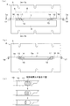
図1〜図4に示す実施例1の押出成形装置は、図5に示すような陶板壁材素材50を押出成形するためのものである。
陶板壁材素材50は、平板状の本体51と、本体51の幅方向左端の厚さ方向下部から幅方向左方へ延びるアンダーラップ52と、本体51の幅方向右端の厚さ方向上部から幅方向右方へに突出するオーバーラップ53とからなり、幅(オーバーラップ53及びアンダーラップ52を含む全幅)は360mm、厚さは20mm、長さは900〜2000mm(押出成形後に所望の長さに切断したもの)である。図5(c)に示すように、隣り合う一方の陶板壁材素材50のアンダーラップ52と他方の陶板壁材素材50のオーバーラップ53とを重ね、取付金具54により建物の壁部に取り付けられるものであり、いわゆる働き幅は300mmである。
The extrusion molding apparatus of Example 1 shown in FIGS. 1 to 4 is for extruding a
The porcelain
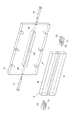
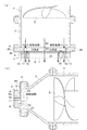
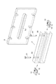
押出成形装置は、スクリュー2を有する土練機1と、土練機1の出口に接続された溜め箱3と、溜め箱3の出口に接続された口金装置4とを備えたものであり、この基本的構成は公知のものである。
The extrusion molding apparatus includes a
口金装置4は、溜め箱3に接続される口金取付板5と、口金取付板5の下流側に取り付けられた口金6とからなる。
The
口金6は、横長板状の上部材8と下部材9との間に、左右に間隔をおいた左端部材10と右端部材13とが挟まれて構成され、これらの間に横長の成形用押出孔7が形成されている。
左端部材10の成形用押出孔7に面する端部は、前記アンダーラップ52を形成する段付き形状に形成されている。また、左端部材10には、土練機1から流れる粘土の左側部を捨土として押し出すための左側の捨土用押出孔11が、成形用押出孔7に対して仕切壁12を介して設けられている。
右端部材13の成形用押出孔7に面する端部は、前記オーバーラップ53を形成する段付き形状に形成されている。また、右端部材13には、土練機1から流れる粘土の右側部を捨土として押し出すための右側の捨土用押出孔14が、成形用押出孔7に対して仕切壁15を介して設けられている。
捨土用押出孔11,14は、ストレート孔であり、その出口の面積は250〜350mm2であり、孔形状は長円形である。
The
An end portion of the
The end of the
捨土for extrusion holes 11 and 14 are straight holes, the area of the outlet is 250~350Mm 2, hole shape is oval.
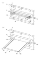
口金取付板5の中央部には、図2(b)等に示すように、成形用押出孔7と左側及び右側の捨土用押出孔11,14をまとめた大きさよりも一回り大きい横長の口金上流側通路5aが貫設され、これらの押出孔7,11,14に連通している。
As shown in FIG. 2B and the like, the center portion of the
さらに、土練機1から流れる粘土の両側部に圧力を付与するための、捨土用押出孔11,14の出口を上流側へ投影した投影範囲の少なくとも一部に重なるように配置された調整部材が設けられている。
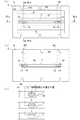
実施例1における調整部材は、口金取付板5の左端面から口金上流側通路まで形成されたねじ孔16に螺着された左側の調整ボルト17と、口金取付板5の右端面から口金上流側通路5aまで形成されたねじ孔18に進退調節可能に螺合した左側の調整ボルト19である。調整ボルト17,19の先端部が、口金上流側通路5aに進入して、さらに前記投影範囲に重なり得るようになっている。そして、調整ボルト17,19を変位(ねじ孔16,18で進退)させて、図2(c)にハッチングで示すように、調整ボルト17,19の先端部と前記投影範囲との重なり量をゼロから投影範囲の全部までのレンジで変えることができる。また、調整ボルト17,19は捨土用押出孔11,14の入口よりも上流側にあり、捨土用押出孔11,14の入口から調整ボルト17,19までの距離は約5mmである。
Furthermore, the adjustment arrange | positioned so that it may overlap with at least one part of the projection range which projected the exit of the
In the first embodiment, the adjustment member includes the
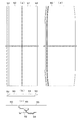
以上のように構成された押出成形装置によれば、
土練機1から流れる粘土(図1(a)の中央の矢印参照)を、口金6に設けられた横長の成形用押出孔7より押し出して、幅200〜700mm、厚さ10〜30mm、押出長600mm以上の陶板壁材素材50を押出成形すると同時に、
土練機1から流れる粘土の両端部(図1(a)の左側の矢印及び右側の矢印参照)を、口金6における成形用押出孔7の両横に仕切壁12,15を介して設けられた捨土用押出孔11,14から捨土55,56として押し出すとともに、捨土用押出孔11,14の出口を上流側へ投影した投影範囲の少なくとも一部に重なるように配置された調整ボルト17,19により圧力を付与することができる。
According to the extrusion molding apparatus configured as described above,
The clay flowing from the kneader 1 (see the arrow at the center of FIG. 1 (a)) is extruded from a horizontally
Both ends of the clay flowing from the kneader 1 (see the left arrow and the right arrow in FIG. 1A) are provided on both sides of the
土練機1から流れる粘土の中央部は成形用押出孔7に向かって流れ、土練機1から流れる粘土の両端部は捨土用押出孔11,14に向かって流れ、両者の境界部の粘土は、仕切壁12,15の直ぐ上流の分流点で成形用押出孔7に向かう流れと捨土用押出孔11,14に向かう流れとに分かれる。
調整ボルト17,19は、捨土用押出孔11,14の出口を上流側へ投影した投影範囲の少なくとも一部に重なるように配置されており、従って捨土用押出孔11,14の出口よりも上流側の箇所、すなわち分流点に近い箇所から、粘土に圧力を付与する。そのため、調整ボルト17,19は、分流点から捨土用押出孔11,14に向かう流れに対してだけでなく、分流点から成形用押出孔7に向かう流れに対しても近距離から制御を加えやすくなり、圧力付与による粘土の制御が効率よくできる。
The central part of the clay flowing from the
The adjusting
このため、調整ボルト17,19を変位(ねじ孔16,18で進退)させて、図2(c)にハッチングで示すように、調整ボルト17,19の先端部と前記投影範囲との重なり量を変えることにより、粘土の制御を精度良く行うことができ、その調節の結果、図5(a)に示すような幅300mm、厚さ20mm、押出長900mmの陶板壁材素材50を押出成形したところ、押出長方向の端部でも幅が一定になり真っ直ぐに成形することができた。
これに対し、調整ボルト17,19が無い場合には、図5(d)に示すように、陶板壁材素材50’は押出長方向の端部で幅が減じるように樽形に変形した。
Therefore, the
On the other hand, when the adjusting
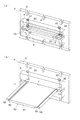
図6〜図9に示す実施例2の押出成形装置は、調整部材においてのみ実施例1と相違するものであり、その余の実施例1と共通する部分については説明を省略する。
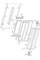
実施例2における調整部材は、口金取付板5と口金6との間に挟着されたガイド板20に対して上下変位調節可能な左右の調整プレート25,26である。ガイド板20の中央部には、成形用押出孔7と左側及び右側の捨土用押出孔11,14をまとめた大きさよりも一回り大きい通孔21が貫設されている。ガイド板20の上流側の面には左右両端部以外に凹所22が形成されている。凹所22には、左右の調整プレート25,26とその間の中間プレート23とが上方から差し込まれ、左右の調整プレート25,26の下端部が、前記捨土用押出孔11,14の出口を上流側へ投影した投影範囲の少なくとも一部に重なり得るようになっている。そして、調整プレート25,26を上下変位調節(上下にスライド)して、図7(c)にハッチングで示すように、調整プレート25,26の先端部と前記投影範囲との重なり量をゼロから投影範囲の全部までのレンジで変えることができる。また、調整プレート25,26は捨土用押出孔11,14の入口よりも上流側にあり、捨土用押出孔11,14の入口から調整プレート25,26までの距離は約10mmである。
The extrusion molding apparatus according to the second embodiment shown in FIGS. 6 to 9 is different from the first embodiment only in the adjustment member, and the description of the other parts common to the first embodiment is omitted.
The adjustment members in the second embodiment are left and
実施例2の押出成形装置によっても、実施例1と同様に、陶板壁材素材50を押出成形すると同時に、捨土用押出孔11,14から捨土を押し出し、その際に調整プレート25,26により粘土を制御して、実施例1と同様の作用効果を得ることができる。
Similarly to the first embodiment, the extrusion molding apparatus of the second embodiment extrudes the porcelain
図10〜図13に示す実施例3の押出成形装置は、調整部材においてのみ実施例1と相違するものであり、その余の実施例1と共通する部分については説明を省略する。
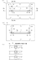
実施例3における調整部材は、口金6の上部材8の上端面の左寄り部から捨土用押出孔11まで形成されたねじ孔30に螺着された左側の調整ボルト31と、上部材8の上端面の右寄り部から捨土用押出孔14まで形成されたねじ孔32に螺着された右側の調整ボルト33である。調整ボルト31,33の下端部が捨土用押出孔11,14の途中部に進入して、捨土用押出孔11,14の出口を上流側へ投影した投影範囲の一部に重なり得るようになっている。そして、調整ボルト31,33を変位(ねじ孔30,32で進退)させて、図11(c)にハッチングで示すように、調整ボルト31,33の先端部と前記投影範囲との重なり量をゼロから投影範囲の全部までのレンジで変えることができる。
The extrusion molding apparatus according to the third embodiment shown in FIGS. 10 to 13 is different from the first embodiment only in the adjustment member, and the description of the other parts common to the first embodiment is omitted.
In the third embodiment, the adjustment member includes an
実施例3の押出成形装置によっても、実施例1と同様に、陶板壁材素材50を押出成形すると同時に、捨土用押出孔11,14から捨土を押し出し、その際に調整ボルト31,33により粘土を制御して、実施例1と同様の作用効果を得ることができる。調整ボルト31,33から分流点までの距離は、実施例1と比べればやや遠くなるが、特許文献2と比べれば近い。
Similarly to Example 1, the extrusion molding apparatus of Example 3 simultaneously extrudes the
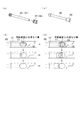
図14に示す実施例4の押出成形装置は、調整部材においてのみ実施例1と相違するものであり、その余の実施例1と共通する部分については説明を省略する。
実施例4における調整部材は、実施例1の調整ボルト17,19よりも外径が小さい調整ボルト35(37:右側は図示略)と、調整ボルト35(37)の先端部に着脱可能な、調整ボルト35(37)よりも外径が大きい調整体36(38:右側は図示略)であり、基本的な作用は実施例1と同様である。但し、図14(a)のように調整体36(38)を取り外した調整ボルト35(37)単独のときは、図14(b)にハッチングで示すように、捨土用押出孔(11,14)の出口を上流側へ投影した投影範囲の全部には重なり得ない。図14(c)のように調整ボルト35(37)に調整体36(38)を取り付けたときは、図14(d)にハッチングで示すように、前記投影範囲の全部に重なり得る。このように、調整体36(38)の着脱(交換の1種)によっても、前記投影範囲との重なり量を変えることができる。
The extrusion molding apparatus according to the fourth embodiment shown in FIG. 14 is different from the first embodiment only in the adjustment member, and the description of the other parts common to the first embodiment is omitted.
The adjustment member according to the fourth embodiment can be attached to and detached from the adjustment bolt 35 (37: the right side is not shown) having an outer diameter smaller than that of the
実施例4の押出成形装置によっても、実施例1と同様に、陶板壁材素材(50)を押出成形すると同時に、捨土用押出孔(11,14)から捨土を押し出し、その際に調整ボルト35(37)及び調整体36(38)により粘土を制御して、実施例1と同様の作用効果を得ることができる。 Similarly to Example 1, the extrusion molding apparatus of Example 4 extrudes the porcelain plate wall material (50), and simultaneously extrudes the soil from the soiling extrusion holes (11, 14), and adjusts at that time. By controlling the clay with the bolts 35 (37) and the adjusting body 36 (38), the same effects as in the first embodiment can be obtained.
図15に示す実施例5の押出成形装置は、調整部材に捨土用押出孔の出口からの距離を変えられる機能を加えた点においてのみ実施例1と相違するものであり、その余の実施例1と共通する部分については説明を省略する。
実施例5における調整部材は、実施例1と同様の調整ボルト17,19であるが、口金取付板5にねじ孔16,18がそれぞれ粘土の流れ方向に複数並べて設けられ、各複数のねじ孔16,18のいずれか一つに選択的に調整ボルト17,19を螺着させることにより、捨土用押出孔11,14の出口から調整ボルト17,19までの距離を変えられるようになっている。本例では、調整ボルト17,19は捨土用押出孔11,14の入口よりも上流側にあり、捨土用押出孔11,14の入口から調整ボルト17,19までの距離を3〜40mmのレンジで変えられる。なお、調整ボルト17,19を螺着しないねじ孔16,18は、閉鎖ボルト(図示略)を螺着して閉鎖する。
The extrusion molding apparatus of Example 5 shown in FIG. 15 is different from Example 1 only in that a function capable of changing the distance from the exit of the disposal extrusion hole is added to the adjustment member. A description of portions common to Example 1 is omitted.
The adjustment members in the fifth embodiment are the
実施例5の押出成形装置によっても、実施例1と同様に、陶板壁材素材(50)を押出成形すると同時に、捨土用押出孔11,14から捨土を押し出し、その際に調整ボルト17,19により粘土を制御して、実施例1と同様の作用効果を得ることができる。また、捨土用押出孔11,14の出口から調整ボルト17,19までの距離を変えることにより、調整ボルト17,19による粘土の制御をよりきめ細かく細かく行うことができる。
Also in the extrusion molding apparatus of Example 5, as in Example 1, the earthen wall material (50) is extruded and simultaneously, the waste is pushed out from the extrusion holes 11 and 14, and the adjusting
図16に示す実施例6の押出成形装置は、調整部材に捨土用押出孔の出口からの距離を変えられる機能を加えた点においてのみ実施例2と相違するものであり、その余の実施例2と共通する部分については説明を省略する。
実施例6における調整部材は、実施例2と同様の調整プレート25,26であるが、各調整プレート25,26の、上流側に2枚のスペーサ板27,27を重ねて当てるか、上流側及び下流側に1枚ずつスペーサ板27,27を当てるか、下流側に2枚のスペーサ板27,27を重ねて当てるか、を選択することにより、捨土用押出孔11,14の出口から調整プレート25,26までの距離を変えられるようになっている。本例では、プレート25,26は捨土用押出孔11,14の入口よりも上流側にあり、捨土用押出孔11,14の入口から調整プレート25,26までの距離を10〜25mmのレンジで変えられる。
The extrusion molding apparatus of Example 6 shown in FIG. 16 is different from Example 2 only in that a function that can change the distance from the exit of the disposal extrusion hole is added to the adjustment member. A description of portions common to Example 2 is omitted.
The adjustment members in the sixth embodiment are the
実施例6の押出成形装置によっても、実施例2と同様に、陶板壁材素材(50)を押出成形すると同時に、捨土用押出孔11,14から捨土を押し出し、その際に調整プレート25,26により粘土を制御して、実施例2と同様の作用効果を得ることができる。また、捨土用押出孔11,14の出口から調整プレート25,26までの距離を変えることにより、調整プレート25,26による粘土の制御をよりきめ細かく行うことができる。
Similarly to Example 2, the extrusion molding apparatus of Example 6 extrudes the ceramic plate wall material (50) and simultaneously pushes out the soil from the soiling extrusion holes 11 and 14, and the
なお、本発明は前記実施例の構成に限定されるものではなく、発明の趣旨から逸脱しない範囲で適宜変更して具体化することもできる。
(1)陶板壁材素材は、中実のものに限定されず、押出長方向に延びる複数の孔を備えた中空のものでもよい。この中空のものは、公知の複数の中玉(特許文献2を参照)を成形用押出孔に入り込ませた押出成形装置により、押出成形することができる。
In addition, this invention is not limited to the structure of the said Example, In the range which does not deviate from the meaning of invention, it can change suitably and can be actualized.
(1) The ceramic plate wall material is not limited to a solid material, and may be a hollow material having a plurality of holes extending in the extrusion length direction. This hollow can be extruded by an extrusion molding apparatus in which a plurality of known center balls (see Patent Document 2) are inserted into the molding extrusion holes.
1 土練機
6 口金
7 成形用押出孔
11 捨土用押出孔
12 仕切壁
14 捨土用押出孔
15 仕切壁
16 ねじ孔
17 調整ボルト
18 ねじ孔
19 調整ボルト
25 調整プレート
26 調整プレート
27 スペーサ板
30 ねじ孔
31 調整ボルト
32 ねじ孔
33 調整ボルト
35 調整ボルト
36 調整体
50 陶板壁材素材
55 捨土
56 捨土
DESCRIPTION OF
Claims (4)
土練機から流れる粘土の両端部を、口金における成形用押出孔の両横に仕切壁を介して設けられた捨土用押出孔から捨土として押し出すとともに、捨土用押出孔の出口を上流側へ投影した投影範囲の少なくとも一部に重なるように配置された調整部材により圧力を付与することを特徴とする陶板壁材素材の押出成形方法。 At the same time as extruding the clay flowing from the clay kneader through a horizontally shaped extrusion hole provided in the die and extruding a ceramic wall material having a width of 200 to 700 mm, a thickness of 10 to 30 mm, and an extrusion length of 600 mm or more,
Both ends of the clay flowing from the clay kneader are pushed out as waste soil from the waste extrusion holes provided on both sides of the extrusion holes in the die via the partition walls, and the outlet of the waste extrusion holes is upstream. A method for extruding a ceramic board wall material, wherein pressure is applied by an adjustment member arranged to overlap at least a part of a projection range projected to the side.
土練機から流れる粘土を押し出して、幅200〜700mm、厚さ10〜30mmの陶板壁材素材を押出成形するための、口金に設けられた横長の成形用押出孔と、
土練機から流れる粘土の両側部を捨土として押し出すための、口金における成形用押出孔の両横に仕切壁を介して設けられた捨土用押出孔と、
土練機から流れる粘土の両側部に圧力を付与するための、捨土用押出孔の出口を上流側へ投影した投影範囲の少なくとも一部に重なるように配置された調整部材とを含むことを特徴とする陶板壁材素材の押出成形装置。 Equipped with a kneader and a base
Extruded clay flowing from a clay kneader, and extruding a ceramic board wall material having a width of 200 to 700 mm and a thickness of 10 to 30 mm, a horizontally long extrusion hole provided in the base,
For extruding both sides of the clay flowing from the kneader as waste soil, the waste extrusion holes provided on both sides of the extrusion holes in the die via the partition walls,
An adjustment member arranged to overlap at least a part of the projection range in which the outlet of the disposal extrusion hole is projected upstream to apply pressure to both sides of the clay flowing from the clay kneader. A feature of extrusion equipment for ceramic wall material.
Priority Applications (1)
| Application Number | Priority Date | Filing Date | Title |
|---|---|---|---|
| JP2016158114A JP6778048B2 (en) | 2016-08-10 | 2016-08-10 | Extrusion molding method and extrusion molding equipment for porcelain wall material |
Applications Claiming Priority (1)
| Application Number | Priority Date | Filing Date | Title |
|---|---|---|---|
| JP2016158114A JP6778048B2 (en) | 2016-08-10 | 2016-08-10 | Extrusion molding method and extrusion molding equipment for porcelain wall material |
Publications (2)
| Publication Number | Publication Date |
|---|---|
| JP2018024185A true JP2018024185A (en) | 2018-02-15 |
| JP6778048B2 JP6778048B2 (en) | 2020-10-28 |
Family
ID=61194818
Family Applications (1)
| Application Number | Title | Priority Date | Filing Date |
|---|---|---|---|
| JP2016158114A Active JP6778048B2 (en) | 2016-08-10 | 2016-08-10 | Extrusion molding method and extrusion molding equipment for porcelain wall material |
Country Status (1)
| Country | Link |
|---|---|
| JP (1) | JP6778048B2 (en) |
Cited By (2)
| Publication number | Priority date | Publication date | Assignee | Title |
|---|---|---|---|---|
| CN109571707A (en) * | 2019-01-21 | 2019-04-05 | 石家庄铁道大学 | Clay 3D printing extrusion device |
| CN111472312A (en) * | 2020-04-17 | 2020-07-31 | 武汉理工大学 | Method and device for controlling incident angle of water spray rod of suction nozzle of washing and sweeping vehicle |
-
2016
- 2016-08-10 JP JP2016158114A patent/JP6778048B2/en active Active
Cited By (3)
| Publication number | Priority date | Publication date | Assignee | Title |
|---|---|---|---|---|
| CN109571707A (en) * | 2019-01-21 | 2019-04-05 | 石家庄铁道大学 | Clay 3D printing extrusion device |
| CN111472312A (en) * | 2020-04-17 | 2020-07-31 | 武汉理工大学 | Method and device for controlling incident angle of water spray rod of suction nozzle of washing and sweeping vehicle |
| CN111472312B (en) * | 2020-04-17 | 2021-01-19 | 武汉理工大学 | Method and device for controlling incident angle of water spray rod of suction nozzle of washing and sweeping vehicle |
Also Published As
| Publication number | Publication date |
|---|---|
| JP6778048B2 (en) | 2020-10-28 |
Similar Documents
| Publication | Publication Date | Title |
|---|---|---|
| EP2184766A3 (en) | Directional extruded bead control | |
| WO2005110934A2 (en) | Method and device for controlling the temperature during glass production | |
| JP2018024185A (en) | Extrusion molding method of porcelain plate wall raw material and extrusion molding device | |
| WO2006026301A3 (en) | Open cavity extrusion dies | |
| JP7213275B2 (en) | Extrusion dies and extruders | |
| KR20090129878A (en) | Double extrusion panel manufacturing system and method using plastic materials | |
| CN212331773U (en) | Extrusion flow distribution adjusting device | |
| KR101732805B1 (en) | Apparatus for simultaneous molding of tiles | |
| JP4952220B2 (en) | Resin molding die, resin molding apparatus, and resin film manufacturing method | |
| CN203246061U (en) | Square shoulder type plastic extrusion flat die head | |
| US10343322B2 (en) | Device for extruding elastomer mixtures | |
| US20080271671A1 (en) | Extrusion Nozzle for Extruding Hollow Profiles | |
| CN103213266B (en) | Flat shoulder plastic extrusion flat-mould head | |
| CN207789678U (en) | Hollow grid plate extrusion die | |
| CN213227425U (en) | Novel multi-color staggered adjustable width extrusion die | |
| CN102950748A (en) | Sheet extrusion die | |
| CN205989490U (en) | A kind of stable extruder sizing die head of extrusion | |
| CN108044909A (en) | 2150mm-2450mmEVA-POE solar energy membrane sheet die runners | |
| CN204773477U (en) | Film hydrostomia extrusion equipment's mould | |
| CN213946851U (en) | Vacuum extruder forming assembly suitable for wet-method extrusion of large-size ceramic tiles | |
| DE19946523C2 (en) | Process and device for the production of plastic foam strands of great thickness | |
| KR101725131B1 (en) | Mixing type extruder head for sheet forming | |
| JP3944952B2 (en) | Green sheet mold | |
| DE102013103255A1 (en) | Process for producing a thermoplastic integral foam board | |
| JP2015047791A (en) | Rubber molding apparatus |
Legal Events
| Date | Code | Title | Description |
|---|---|---|---|
| A621 | Written request for application examination |
Free format text: JAPANESE INTERMEDIATE CODE: A621 Effective date: 20190607 |
|
| A977 | Report on retrieval |
Free format text: JAPANESE INTERMEDIATE CODE: A971007 Effective date: 20200122 |
|
| A131 | Notification of reasons for refusal |
Free format text: JAPANESE INTERMEDIATE CODE: A131 Effective date: 20200218 |
|
| A521 | Request for written amendment filed |
Free format text: JAPANESE INTERMEDIATE CODE: A523 Effective date: 20200416 |
|
| TRDD | Decision of grant or rejection written | ||
| A01 | Written decision to grant a patent or to grant a registration (utility model) |
Free format text: JAPANESE INTERMEDIATE CODE: A01 Effective date: 20200929 |
|
| A61 | First payment of annual fees (during grant procedure) |
Free format text: JAPANESE INTERMEDIATE CODE: A61 Effective date: 20201009 |
|
| R150 | Certificate of patent or registration of utility model |
Ref document number: 6778048 Country of ref document: JP Free format text: JAPANESE INTERMEDIATE CODE: R150 |
|
| R250 | Receipt of annual fees |
Free format text: JAPANESE INTERMEDIATE CODE: R250 |