JP2018018063A - Luminous decoration object - Google Patents

Luminous decoration object Download PDF

Info

Publication number
JP2018018063A
JP2018018063A JP2017127875A JP2017127875A JP2018018063A JP 2018018063 A JP2018018063 A JP 2018018063A JP 2017127875 A JP2017127875 A JP 2017127875A JP 2017127875 A JP2017127875 A JP 2017127875A JP 2018018063 A JP2018018063 A JP 2018018063A
Authority
JP
Japan
Prior art keywords
luminous
decorative member
opening
light
decoration
Prior art date
Legal status (The legal status is an assumption and is not a legal conclusion. Google has not performed a legal analysis and makes no representation as to the accuracy of the status listed.)
Pending
Application number
JP2017127875A
Other languages
Japanese (ja)
Other versions
JP2018018063A5 (en
Inventor
紗葵 三浦
Saki Miura
紗葵 三浦
哲浩 中村
Tetsuhiro Nakamura
中村  哲浩
Current Assignee (The listed assignees may be inaccurate. Google has not performed a legal analysis and makes no representation or warranty as to the accuracy of the list.)
Citizen Watch Co Ltd
Original Assignee
Citizen Watch Co Ltd
Priority date (The priority date is an assumption and is not a legal conclusion. Google has not performed a legal analysis and makes no representation as to the accuracy of the date listed.)
Filing date
Publication date
Application filed by Citizen Watch Co Ltd filed Critical Citizen Watch Co Ltd
Publication of JP2018018063A publication Critical patent/JP2018018063A/en
Publication of JP2018018063A5 publication Critical patent/JP2018018063A5/ja
Pending legal-status Critical Current

Links

Images

Landscapes

  • Illuminated Signs And Luminous Advertising (AREA)

Abstract

PROBLEM TO BE SOLVED: To provide a luminous decoration object which efficiently uses external light, which draws a gradation pattern, character, and pattern by light emission of a luminous member in a dark place, for achieving visibility and decorative property with an interest.SOLUTION: There is provided a luminous decoration object 150 which comprises visibility and decorative property in a dark place, comprising; a luminous member for applying visibility in a dark place; and a decorative member 2 having a visibility and decorative property in a bright place. The luminous member and decorative member 2 are arranged in a same area, and in the same area, there are areas having different light transmissivity.SELECTED DRAWING: Figure 1A

Description

本発明は、腕時計、携帯電子機器、各種計器類等に適用する夜光性装飾物に関し、日中の明るい場所における視認性及び装飾性と、夜間の暗い場所での視認性及び装飾性とを付与した夜光性装飾物に関する。   The present invention relates to a luminous ornament applied to a wristwatch, a portable electronic device, various instruments, and the like, and imparts visibility and decoration in a bright place during the day and visibility and decoration in a dark place at night. Related to luminescent decorations.

例えば、指針を用いる腕時計において、夜間の暗い場所(以下、「暗所」と記載する)でも時刻が視認できるように文字板及び指針の一部に蓄光性部材(以下、「夜光性部材」と記載する)を印刷、又はシート状にして貼り付けるなどの方法によって蓄光部を形成して、日中の明るい場所(以下、「明所」と記載する)では外部光により蓄光部にエネルギーを蓄え、夜間の暗所では蓄光部を発光させて、時刻の視認を可能にしたものが知られている。   For example, in a wristwatch that uses a pointer, a luminous member (hereinafter referred to as a “nocturnal member”) is used on a dial and part of the pointer so that the time can be visually recognized even in a dark place at night (hereinafter referred to as “dark place”). The phosphorescent part is formed by printing or sticking it in the form of a sheet, and in a bright place in the daytime (hereinafter referred to as “light place”), energy is stored in the phosphorescent part by external light. In a dark place at night, a phosphorescent part is made to emit light so that the time can be visually recognized.

このような腕時計では、暗所では蓄光部の発光により時刻を知ることができるが、明所では文字板又は指針に形成した夜光性部材が特有の白緑色系の色に見えて装飾性に欠けるという問題を指摘され改善が望まれていた。背景としては、腕時計は時刻を報知する装置としてだけでなく、装飾品としての役割があるためである。   In such a wristwatch, the time can be known by light emission of the phosphorescent part in a dark place, but in a bright place, the luminous member formed on the dial or the pointer looks like a specific white-green color and lacks decoration. The problem was pointed out and improvement was desired. This is because the wristwatch not only serves as a device for notifying the time but also serves as a decorative item.

このような要求に対しては、従来、例えば指針式の腕時計を例として、文字板を構成する部材及び夜光性部材の構造を工夫することによって、明所では夜光性部材が目立たないようにして文字板に印刷された時刻表示目盛りを視認して時刻を知り、暗所では明所で蓄光された夜光性部材の発光をバックライトとして用いて時刻表示目盛りを照明し時刻表示目盛りを黒い影として視認して時刻を知るような提案がなされている。(例えば、特許文献1参照。)。   In response to such a demand, conventionally, for example, a pointer-type wristwatch is taken as an example, and the structure of the member constituting the dial and the luminous member is devised so that the luminous member is not conspicuous in a bright place. The time display scale printed on the dial is visually recognized to know the time, and in the dark, the time display scale is illuminated as a black shadow by using the light emitted from the luminous material stored in the light as a backlight. Proposals have been made to know the time by visual recognition. (For example, refer to Patent Document 1).

特許文献1に示した従来技術は、文字板の構造として金属性の下面板とその上方に配置する上面部材とから構成され、下面板の上面の全面又は一部にセラミックスをベースにした金属酸化物からなる夜光性部材を塗布し、さらに夜光性部材の表面にクリアラッカーを塗布し、さらにクリアラッカーの上面を研磨して平面化することで上面部材を密着させて接着剤等により固着する構造になっている。また、上面部材はサファイアガラスや水晶等の鉱物又は合成樹脂などの極薄の透明材料を用いている。腕時計の文字板をこのような構造にすることによって、明所では上面部材に印刷、又は金属線を接着することにより形成された時刻表示目盛りを視認して時刻を知り、暗所では明所で蓄光された夜光性部材による上面部材の背後からの照明(バックライト)により、時刻表示目盛りを黒い影として視認して時刻を知ることができる。その結果、明所と暗所では異なった文字板の表示ができるようになっている。   The prior art shown in Patent Document 1 is composed of a metallic lower surface plate and an upper surface member disposed thereabove as a structure of a dial plate, and a metal oxide based on ceramics on the entire upper surface or a part of the lower surface plate. A structure in which a luminous member made of a material is applied, a clear lacquer is further applied to the surface of the luminous member, and the upper surface of the clear lacquer is polished and planarized so that the upper surface member is adhered and fixed with an adhesive or the like It has become. The top member is made of a very thin transparent material such as a mineral such as sapphire glass or quartz, or a synthetic resin. By making the watch dial like this, it is possible to know the time by visually checking the time display scale formed by printing or bonding a metal wire on the upper surface member in the light place, and in the light place in the dark place. Illumination (backlight) from behind the upper surface member by the stored luminous member allows the time display scale to be visually recognized as a black shadow to know the time. As a result, different dials can be displayed in light and dark places.

特開平7−43477号公報(第1頁、図2)Japanese Unexamined Patent Publication No. 7-43477 (first page, FIG. 2)

しかしながら、特許文献1に示す従来技術は、時刻表示目盛りが印刷された上面部材の背後から夜光性部材により照明することで時刻表示目盛りを黒い影として視認するようにしているので、時刻を知ることはできるものの、明所における時刻表示目盛りの形状と暗所における時刻表示目盛りの形状に差がなく、しかも黒い影として視認されるため、趣の
ある装飾性を得難いという問題がある。尚、下面板の上面に格子状に区画された夜光性部材を配設し、半透明のすりガラス状の上面部材越しに満月の夜の障子を通した月光を見るような装飾効果を得る提案もあるが、半透明のすりガラス状の上面部材越しに夜光性部材特有の白緑色系の色味が見えてしまうのである。また上面部材に極薄の和紙や布地などを埋設して装飾性を保つ提案もされているが、透過光の明るさを損なってしまうという新たな問題が発生するのである。
However, the prior art disclosed in Patent Document 1 knows the time because the time display scale is visually recognized as a black shadow by illuminating with a luminous member from behind the upper surface member on which the time display scale is printed. However, since there is no difference between the shape of the time display scale in the bright place and the shape of the time display scale in the dark place, and it is visually recognized as a black shadow, there is a problem that it is difficult to obtain an attractive decoration. There is also a proposal to obtain a decorative effect such that a nocturnal member divided in a lattice shape is arranged on the upper surface of the bottom plate, and the moonlight passing through a shoji of the full moon is seen through the translucent ground glass-like upper surface member. However, the white-green color peculiar to the luminous member can be seen through the translucent ground glass-like upper surface member. Although proposals have been made to embed ultra-thin Japanese paper or fabric in the upper surface member to maintain the decorativeness, there is a new problem that the brightness of transmitted light is impaired.

このように、特許文献1に示した従来技術は、夜光性部材の発光を上面部材の背後からのバックライトとして用いる方式であるので、暗所では、明所と異なる趣のある装飾性を得難い。一方、背後からの照明を遮るような金属部材(例えばインジケータ等)を多用できないので装飾性に制約が生じる。また、上面部材越しに夜光性部材特有の白緑色系の色味が見えてしまい装飾性に欠けるという問題を解消することはできない。   As described above, the prior art disclosed in Patent Document 1 is a method in which the light emitted from the luminous member is used as a backlight from behind the upper surface member, so that it is difficult to obtain a decorative appearance that is different from the bright place in a dark place. . On the other hand, there are restrictions on the decorativeness because a metal member (for example, an indicator or the like) that blocks illumination from behind cannot be used frequently. Moreover, the white-green color characteristic peculiar to a luminescent member can be seen through the upper surface member, and the problem of lack of decorativeness cannot be solved.

そこで、本発明の目的は、上記問題点を解決しようとするものであり、外部光を有効に利用する夜光性装飾物であって、暗所では夜光性部材の発光によりグラデーション模様、文字、絵柄などを描いて趣のある視認性及び装飾性を付与した夜光性装飾物を提供することである。   Accordingly, an object of the present invention is to solve the above-described problems, and is a luminescent ornament that effectively uses external light, and in a dark place, a gradation pattern, characters, and patterns are emitted by light emission of the luminescent member. It is to provide a nocturnal decoration that has been given a gorgeous visibility and decoration.

また、本発明の他の目的は、明所では所望の金属感や所望の色彩を有する文字や絵柄などを描くことができる視認性及び装飾性を付与するとともに、夜光性部材に特有の白緑色系の色味を目立たなくした夜光性装飾物を提供することである。   Another object of the present invention is to provide visibility and decorativeness capable of drawing letters and designs having a desired metallic feeling and desired color in a bright place, and to provide a white-green color peculiar to a luminous member. The object is to provide a nocturnal decoration that makes the color of the system inconspicuous.

本発明における夜光性装飾物の構成は以下の通りである。
暗所での視認性及び装飾性を付与した夜光性装飾物であって、暗所で視認性を付与するための夜光性部材と、明所での視認性及び装飾性を有する装飾部材と、を備え夜光性部材と装飾部材とが同一領域内に配置され、同一領域内に、光透過率が異なる領域を有することを特徴とする。
The composition of the luminous ornament in the present invention is as follows.
A luminous ornament that has been provided with visibility and decoration in a dark place, a luminous member for imparting visibility in the dark, and a decoration member having visibility and decoration in a bright place, The nocturnal member and the decorative member are arranged in the same region, and the same region has regions having different light transmittances.

これにより、夜光性装飾物は夜光性部材と装飾部材とが同一領域内に混在して配置され夜光性部材としての機能と装飾部材としての機能とを同時に持つことができるので、暗所では同一領域内に光透過率が異なる領域を形成して発光の明暗差を作り出すことができる。また、明所では金属感などを有することができる。この結果、暗所では、夜光性部材の発光の明暗差によるグラデーション模様、文字などを描いて趣のある視認性及び装飾性を付与した夜光性装飾物を提供することができる。また明所では、金属感などを有する視認性及び装飾性を付与するとともに夜光性部材に特有の白緑色系の色味を目立たなくすることができる。   As a result, the luminous object can be arranged in the same region with the luminous member and the decorative member arranged in the same area so that it can have the function as the luminous member and the function as the decorative member at the same time. A region having different light transmittance can be formed in the region to create a light / dark difference in light emission. Moreover, it can have a metallic feeling in a bright place. As a result, in the dark place, it is possible to provide a nocturnal ornament that is provided with a graceful visibility and decorativeness by drawing a gradation pattern, characters and the like due to the difference in brightness of the luminous member. Further, in a bright place, it is possible to impart visibility and decorativeness with a metallic feeling and make the white-green color characteristic of the nocturnal member inconspicuous.

また、光透過率が異なる領域は、帯状又はドット状の領域であるとよい。   In addition, the regions having different light transmittances are preferably strip-shaped or dot-shaped regions.

これにより、同一領域内に帯状又はドット状の領域を形成して、それぞれの領域の光透過率を変化させることができる。この結果、暗所では、発光の明暗差によるグラデーション模様、文字、絵柄などを描くことができる。また明所では、金属感などを有する文字や形状などを形成することができる。   Thereby, a band-like or dot-like region can be formed in the same region, and the light transmittance of each region can be changed. As a result, in a dark place, it is possible to draw a gradation pattern, a character, a picture, or the like due to the difference in brightness of light emission. In a bright place, characters or shapes having a metallic feeling can be formed.

また、装飾部材は、厚みが異なる領域を有するとよい。   Further, the decorative member may have regions having different thicknesses.

これにより、装飾部材に厚みが異なる領域を形成することによって、光の透過率を変化させることができる。この結果、暗所では、発光の明暗差によるより多様なグラデーション模様、文字、絵柄などを描くことができる。また明所では、金属感などを有する文字や
形状などを形成することができる。
Thereby, the transmittance | permeability of light can be changed by forming the area | region where thickness differs in a decoration member. As a result, in the dark place, it is possible to draw more various gradation patterns, characters, pictures, and the like due to the difference in brightness of light emission. In a bright place, characters or shapes having a metallic feeling can be formed.

また、装飾部材は、金属膜又は樹脂中に着色粒子を含有した着色層であるとよい。   The decorative member may be a colored layer containing colored particles in a metal film or resin.

これにより、装飾部材は所望の領域に金属膜、又は樹脂中に着色粒子を含有した着色層を形成することができる。この結果、暗所では、光透過率を変化させて発光の明暗差によるグラデーション模様、文字、絵柄などを描くことができる。また、着色層に所定の着色粒子を用いることにより、所望の色彩を有するグラデーション模様、文字、絵柄などを描くことができる。また明所では、所望の金属感、又は所望の色彩を有する文字や絵柄を描くことができる。   Thereby, the decoration member can form a colored layer containing colored particles in a metal film or resin in a desired region. As a result, in a dark place, it is possible to draw a gradation pattern, a character, a picture, or the like due to a difference in brightness of light emission by changing the light transmittance. Further, by using predetermined colored particles in the colored layer, it is possible to draw a gradation pattern, a character, a pattern, or the like having a desired color. In a bright place, it is possible to draw characters and designs having a desired metallic feeling or a desired color.

また、着色層は、着色粒子の含有量が異なる領域を有するとよい。   In addition, the colored layer may have a region where the content of the colored particles is different.

これにより、装飾部材の所望の領域の着色層において、樹脂中に含有する着色粒子の含有量(密度)を変化させて光透過率を多様に変えることができる。この結果、暗所では、多様な発光の明暗差を用いたグラデーション模様、文字、絵柄などを描くことができる。また明所では、多様な色彩を有する文字や絵柄を描くことができる。   Thereby, in the colored layer of the desired region of the decorative member, the light transmittance can be variously changed by changing the content (density) of the colored particles contained in the resin. As a result, it is possible to draw gradation patterns, characters, designs, and the like using various light emission contrasts in a dark place. In the bright place, letters and designs with various colors can be drawn.

また、装飾部材は、夜光性部材を露出する複数の開口部を有し、同一領域内に、夜光性部材と装飾部材との混在する比率が異なる領域を有するとよい。   In addition, the decorative member may have a plurality of openings that expose the luminous member, and may have regions having different ratios of the luminous member and the decorative member in the same region.

これにより、装飾部材は、夜光性部材を露出する帯状又はドット状の複数の開口部を有し、夜光性装飾物は夜光性部材と装飾部材とが同一領域内に混在して配置されるので、装飾部材としての機能と夜光性部材としての機能を同時に持つことができる。また、同一領域内に夜光性部材と装飾部材とが混在する比率が異なる領域を有することができるので、暗所では、光透過率を変化させて発光の明暗差をつくることができる。また明所では、金属感を有することができる。この結果、暗所では発光の明暗差によるグラデーション模様、文字、絵柄などを描いて趣のある視認性及び装飾性を付与した夜光性装飾物を提供することができ、また明所では、所望の金属感を有する視認性及び装飾性を付与するとともに夜光性部材に特有の白緑色系の色味を目立たなくすることができる。   Thereby, the decorative member has a plurality of band-shaped or dot-shaped openings that expose the luminous member, and the luminous component is arranged so that the luminous member and the decorative member are mixed in the same region. And, it can have a function as a decorative member and a function as a luminous member at the same time. In addition, since the ratio where the luminous member and the decorative member are mixed can be different in the same region, the light transmittance can be changed in a dark place to create a light-dark difference. In a bright place, it can have a metallic feeling. As a result, it is possible to provide a nocturnal ornament that has a gradual visibility and decoration by drawing gradation patterns, characters, patterns, and the like due to the difference in brightness of light emission in a dark place. Visibility and decorativeness having a metallic feeling can be imparted, and the white-greenish color characteristic of the luminous member can be made inconspicuous.

また、複数の開口部は、同一領域内で、隣り合う開口部の幅が、それぞれ互いに異なっているとよい。   In addition, the plurality of openings may be different from each other in the width of adjacent openings in the same region.

これにより、夜光性装飾物は、装飾部材の隣り合う開口部の幅を互いに変化させることによって、同一領域内に夜光性部材と装飾部材とが混在する比率を変えることができる。この結果、暗所では、光透過率を変化させて発光の明るい領域と暗い領域を形成して明暗差によるグラデーション模様、文字、絵柄など描くことができる。また明所では、所望の金属感を有する視認性及び装飾性を付与するとともに夜光性部材に特有の白緑色系の色味を目立たなくすることができる。   Thus, the luminous decoration can change the ratio of the luminous member and the decorative member mixed in the same region by changing the widths of the adjacent openings of the decorative member. As a result, in a dark place, the light transmittance can be changed to form a bright region and a dark region of light emission, so that a gradation pattern, a character, a pattern, etc. can be drawn due to a difference in brightness. Further, in a bright place, it is possible to impart visibility and decorativeness having a desired metallic feeling and to make the white-green color characteristic of the nocturnal member inconspicuous.

また、複数の開口部は、同一領域内で、複数の開口部の配置密度が異なっているとよい。   The plurality of openings may have different arrangement densities of the plurality of openings in the same region.

これにより、夜光性装飾物は、装飾部材の開口部の配置密度を変えることによって、同一領域内に夜光性部材と装飾部材とが混在する比率を変えることができる。この結果、暗所では、光透過率を変化させて発光の明るい領域と暗い領域を形成して明暗差によるグラデーション模様、文字、絵柄などを描くことができる。また明所では、所望の金属感を有する視認性及び装飾性を付与するとともに夜光性部材に特有の白緑色系の色味を目立たなくすることができる。   Thereby, the luminous decoration can change the ratio in which the luminous member and the decorative member coexist in the same region by changing the arrangement density of the openings of the decorative member. As a result, in a dark place, the light transmittance can be changed to form a bright region and a dark region of light emission, so that a gradation pattern, a character, a pattern, or the like can be drawn due to a light / dark difference. Further, in a bright place, it is possible to impart visibility and decorativeness having a desired metallic feeling and to make the white-green color characteristic of the nocturnal member inconspicuous.

また、複数の開口部のうちの少なくとも1つは、開口部の幅が異なっている部分を有するとよい。   In addition, at least one of the plurality of openings may have a portion where the widths of the openings are different.

これにより、夜光性装飾物は、少なくとも1つの開口部の幅が異なっている部分を有することによって、暗所では光透過率を変化させて発光の明るい領域と暗い領域を形成して明暗差を作ることができる。この結果、暗所では、明暗差によるグラデーション模様、文字、絵柄などを描くことができる。また明所では、所望の金属感を有する視認性及び装飾性を付与するとともに夜光性部材に特有の白緑色系の色味を目立たなくすることができる。   As a result, the luminous ornament has a portion where the width of at least one opening is different, thereby changing the light transmittance in a dark place to form a bright region and a dark region of light emission, thereby reducing the difference in brightness. Can be made. As a result, it is possible to draw a gradation pattern, a character, a pattern, or the like due to a light / dark difference in a dark place. Further, in a bright place, it is possible to impart visibility and decorativeness having a desired metallic feeling and to make the white-green color characteristic of the nocturnal member inconspicuous.

本発明によれば、外部光を有効に利用する夜光性装飾物であって、同一領域内に夜光性部材と装飾部材とが配置され、同一領域内に光透過率の異なる領域を有するので、暗所では夜光性部材の発光の明るい領域と暗い領域とを形成することができる。これにより、発光の明暗差及び色彩によるグラデーション模様、文字、絵柄などを描くことができるので趣のある視認性及び装飾性を付与した夜光性装飾物を提供することができる。また明所では、所望の金属感や所望の色彩を有する文字、形状、絵柄などを描くことができる視認性及び装飾性を付与するとともに、夜光性部材に特有の白緑色系の色味を目立たなくした夜光性装飾物を提供することができる。   According to the present invention, it is a nocturnal ornament that effectively uses external light, and the nocturnal member and the ornamental member are arranged in the same area, and have areas with different light transmittances in the same area. In a dark place, a bright region and a dark region of the luminous member can be formed. Thereby, since a gradation pattern, a character, a pattern, etc. by the brightness difference of light emission and a color can be drawn, the nocturnal ornament which provided quaint visibility and decoration nature can be provided. In addition, in the bright place, visibility and decoration that can draw letters, shapes, patterns, etc. with the desired metallic feeling and desired color are given, and the white-green color characteristic of the luminous member is conspicuous Lost luminescent decoration can be provided.

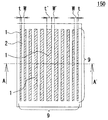
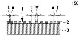
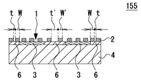
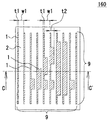
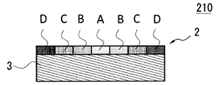
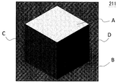
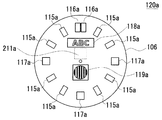
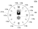
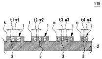
本発明の第1の実施形態を示す平面図である。It is a top view which shows the 1st Embodiment of this invention. 本発明の第1の実施形態を示す断面図である。It is sectional drawing which shows the 1st Embodiment of this invention. 本発明の第2の実施形態を示す平面図である。It is a top view which shows the 2nd Embodiment of this invention. 本発明の第2の実施形態を示す断面図である。It is sectional drawing which shows the 2nd Embodiment of this invention. 本発明の第3の実施形態を示す平面図である。It is a top view which shows the 3rd Embodiment of this invention. 本発明の第3の実施形態を示す断面図である。It is sectional drawing which shows the 3rd Embodiment of this invention. 本発明の第4の実施形態を示す平面図である。It is a top view which shows the 4th Embodiment of this invention. 本発明の第4の実施形態を示す断面図である。It is sectional drawing which shows the 4th Embodiment of this invention. 本発明の第4の実施形態における変形例を示す平面図である。It is a top view which shows the modification in the 4th Embodiment of this invention. 本発明の第5の実施形態を示す平面図である。It is a top view which shows the 5th Embodiment of this invention. 本発明の第5の実施形態を示す断面図である。It is sectional drawing which shows the 5th Embodiment of this invention. 本発明の実施形態の製造工程を示す工程図である。It is process drawing which shows the manufacturing process of embodiment of this invention. 本発明の実施形態の製造工程を示す工程図である。It is process drawing which shows the manufacturing process of embodiment of this invention. 本発明の実施形態の製造工程を示す工程図である。It is process drawing which shows the manufacturing process of embodiment of this invention. 本発明の実施形態の製造工程を示す工程図である。It is process drawing which shows the manufacturing process of embodiment of this invention. 本発明の実施形態における他の構成例を示す断面図である。It is sectional drawing which shows the other structural example in embodiment of this invention. 本発明の実施形態における他の構成例を示す断面図である。It is sectional drawing which shows the other structural example in embodiment of this invention. 本発明の実施形態における他の構成例を示す断面図である。It is sectional drawing which shows the other structural example in embodiment of this invention. 本発明の第6の実施形態を示す断面図である。It is sectional drawing which shows the 6th Embodiment of this invention. 本発明の第6の実施形態における変形例を示す断面図である。It is sectional drawing which shows the modification in the 6th Embodiment of this invention. 本発明の第7の実施形態を示す断面図である。It is sectional drawing which shows the 7th Embodiment of this invention. 第6及び第7の実施形態の暗所での帯状の表示例を示す平面図である。It is a top view which shows the example of a strip | belt-shaped display in the dark place of 6th and 7th embodiment. 第6及び第7の実施形態の暗所での立体形状の表示例を示す平面図である。It is a top view which shows the example of a three-dimensional shape display in the dark place of 6th and 7th embodiment. 本発明を指針式の腕時計に応用した例を示す断面図である。It is sectional drawing which shows the example which applied this invention to the pointer-type wristwatch. 図10の情報表示部の明所での表示例を示す平面図である。It is a top view which shows the example of a display in the bright place of the information display part of FIG. 図10の情報表示部の暗所での表示例を示す平面図である。It is a top view which shows the example of a display in the dark place of the information display part of FIG. 図11Aの情報表示部のシンボルロゴの構成例を示す斜視図である。It is a perspective view which shows the structural example of the symbol logo of the information display part of FIG. 11A. 図11Aの情報表示部のシンボルロゴの構成例を示す断面図である。It is sectional drawing which shows the structural example of the symbol logo of the information display part of FIG. 11A. 図11Aの情報表示部のシンボルマークの構成例を示す斜視図である。It is a perspective view which shows the structural example of the symbol mark of the information display part of FIG. 11A. 図11Aの情報表示部のシンボルマークの構成例を示す断面図である。It is sectional drawing which shows the structural example of the symbol mark of the information display part of FIG. 11A.

以下、図面に基づいて本発明の実施形態を詳述する。ただし、以下に示す実施形態は、本発明の思想を具体化するための夜光性装飾物を例示するものであって、本発明は以下に説明する構成に特定するものではない。特に実施形態に記載されている構成部材の材質、形状、その相対的配置等は特定的な記載がない限りは本発明の範囲をそれのみに限定する趣旨ではなく説明例に過ぎない。また、各図面が示す部材の大きさや位置関係等は説明をわかりやすくするために誇張していることがある。   Hereinafter, embodiments of the present invention will be described in detail with reference to the drawings. However, the embodiment described below exemplifies a luminous ornament for embodying the idea of the present invention, and the present invention is not limited to the configuration described below. In particular, the materials, shapes, relative arrangements, and the like of the constituent members described in the embodiments are merely illustrative examples, and are not intended to limit the scope of the present invention unless otherwise specified. In addition, the size and positional relationship of the members shown in each drawing may be exaggerated for easy understanding.

本発明は、表示部に設けられ外部光を有効に利用する夜光性装飾物であって、同一領域内に夜光性部材と装飾部材とが配置され、同一領域内に光透過率の異なる領域を有することによって、暗所では発光の明暗差によるグラデーション模様、文字、絵柄などを描くことができる。また明所では、所望の金属感や所望の色彩を有する視認性及び装飾性を付与することができる。これにより、趣のある視認性及び装飾性を付与し、また、夜光性部材に特有の白緑色系の色味を目立たなくした夜光性装飾物を提供するものである。   The present invention is a nocturnal ornament that is provided in a display unit and effectively uses external light, and the nocturnal member and the ornamental member are arranged in the same region, and regions having different light transmittances are arranged in the same region. By having it, it is possible to draw a gradation pattern, a character, a picture or the like due to a difference in brightness of light emission in a dark place. In a bright place, visibility and decorativeness having a desired metallic feeling and desired color can be imparted. Thus, it is possible to provide a luminescent decoration that imparts graceful visibility and decorativeness, and that makes the white-green color characteristic of the luminescent member inconspicuous.

このような夜光性装飾物を実現するために、同一領域内の光透過率を変化させる方法として大別すると3つの方法がある。1つ目は、夜光性部材上に金属膜からなる装飾部材を形成し、金属膜に帯状又はドット状の開口部を設けて開口部の幅や大きさ又は配置密度等を変える方法である。2つ目は、夜光性部材上に金属膜又は着色粒子を含有した樹脂からなる装飾部材を形成し、金属膜又は樹脂の厚みを変えることにより光透過率を変える方法である。3つ目は、夜光性部材上に形成した樹脂からなる帯状又はドット状の着色層において含有する着色粒子の含有量(密度)を変える方法である。   In order to realize such a nocturnal ornament, there are roughly three methods for changing the light transmittance in the same region. The first is a method in which a decorative member made of a metal film is formed on a luminous member and a band-like or dot-like opening is provided in the metal film to change the width, size, arrangement density, or the like of the opening. The second is a method of changing the light transmittance by forming a decorative member made of a resin containing a metal film or colored particles on the luminous member and changing the thickness of the metal film or resin. The third is a method of changing the content (density) of colored particles contained in a band-shaped or dot-shaped colored layer made of a resin formed on a luminous member.

以下、図面を用いて夜光性装飾物を詳述する。まず1つ目の金属膜に開口部を形成する方法を第1〜第5の実施形態を用いて説明する。次に、2つ目と3つ目の着色層を形成して着色層の厚み又は着色粒子の含有量(密度)を変える方法を第6〜第8の実施形態(変形例を含む)を用いて説明する。次に、組合せによる方法を第9及び第10の実施形態を用いて説明する。説明にあっては、同一要素には同一番号を付し、重複する説明は省略するものとする。また、発明に関係のない部分は省略している。   Hereinafter, the luminous decoration will be described in detail with reference to the drawings. First, a method of forming an opening in the first metal film will be described using the first to fifth embodiments. Next, a method of changing the thickness of the colored layer or the content (density) of the colored particles by forming the second and third colored layers is used in the sixth to eighth embodiments (including modifications). I will explain. Next, a method by combination will be described using the ninth and tenth embodiments. In the description, the same elements are denoted by the same reference numerals, and redundant descriptions are omitted. Further, parts not related to the invention are omitted.

まず、図1A、図1Bを用いて第1の実施形態を説明する。次に図2A、図2Bを用いて第2の実施形態を、図3A、図3Bを用いて第3の実施形態を、図4A、図4B、図4Cを用いて第4の実施形態(変形例を含む)を、図5A、図5Bを用いて第5の実施形態をそれぞれ説明する。次に、図6A〜図6Dを用いて第1の実施形態の製造工程をそれぞれ説明し、次に、図7A〜図7Cを用いて第1の実施形態における他の構成例(3例)を説明する。次に、図8A〜図8Cを用いて第6及び第7の実施形態(変形例を含む)を説明し、図9A、図9Bを用いて帯状又はドット状の明暗差による表示例を説明する。また、図10〜図13Bを用いて本発明の指針式腕時計への応用例を説明する。   First, the first embodiment will be described with reference to FIGS. 1A and 1B. 2A and 2B, the third embodiment using FIGS. 3A and 3B, and the fourth embodiment (deformation using FIGS. 4A, 4B, and 4C). The fifth embodiment will be described with reference to FIGS. 5A and 5B. Next, the manufacturing process of the first embodiment will be described with reference to FIGS. 6A to 6D, and then another configuration example (three examples) in the first embodiment will be described with reference to FIGS. 7A to 7C. explain. Next, the sixth and seventh embodiments (including modifications) will be described with reference to FIGS. 8A to 8C, and display examples based on a band-like or dot-like brightness difference will be described with reference to FIGS. 9A and 9B. . Moreover, the application example to the pointer type wristwatch of the present invention will be described with reference to FIGS.

[第1の実施形態の説明:図1A、図1B]
まず、図1A、図1Bを用いて本発明の第1の実施形態の夜光性装飾物150を説明する。図1Aは夜光性装飾物150の平面図を示し、図1Bはその要部のA−A’断面を示す。
[Description of First Embodiment: FIGS. 1A and 1B]
First, the luminescent decoration 150 of the 1st Embodiment of this invention is demonstrated using FIG. 1A and FIG. 1B. FIG. 1A shows a plan view of the luminous decoration 150, and FIG. 1B shows a cross section taken along the line AA ′.

第1の実施形態の特徴は、夜光性装飾物150を視認側から見て、装飾部材2に形成された開口パターンにより夜光性部材3と装飾部材2とが同一領域内に混在して配置され、
開口部1の開口幅tと装飾部材2の幅wとをそれぞれ変化させて夜光性部材3と装飾部材2との混在する比率を変えて同一領域内に光透過率が異なる領域を有することにより、開口部の発光に明暗差を設けてグラデーション模様を描けるようにした点である。
The feature of the first embodiment is that the luminous member 3 and the decorative member 2 are mixedly arranged in the same region by the opening pattern formed in the decorative member 2 when the luminous ornament 150 is viewed from the viewing side. ,
By changing the ratio in which the luminous member 3 and the decorative member 2 are mixed by changing the opening width t of the opening 1 and the width w of the decorative member 2, and having regions having different light transmittances in the same region The point is that a gradation pattern can be drawn by providing a difference in brightness in the light emission of the opening.

[構成の説明]
図1A、図1Bにおいて、夜光性装飾物150は、矩形状の夜光性部材3の上面(視認側)に開口パターンを有し、金属膜又は着色粒子を含有した樹脂などで形成した装飾部材2が所定の厚みで積層形成されている。装飾部材2は夜光性部材3と同様の外形形状を有し、開口パターンは複数の帯状の開口部1を備えており、開口部1は、両端側が最も狭い開口幅tであり、両端側から中央部に向かって少しずつ広くなり中央部が最も広い開口幅t’となっている。同様に、装飾部材2の幅w(開口部間の距離)はw〜w’と適宜変化している。このような開口パターンとすることによって、夜光性装飾物150は、各開口部1が全体として発光部9を形成している。また、発光部9の外形形状と大きさは夜光性装飾物150と略同じである。
[Description of configuration]
In FIG. 1A and FIG. 1B, the luminous ornament 150 has an opening pattern on the upper surface (viewing side) of the rectangular luminous member 3 and is formed of a resin or the like containing a metal film or colored particles. Are laminated with a predetermined thickness. The decorative member 2 has the same outer shape as that of the luminous member 3, and the opening pattern includes a plurality of strip-shaped openings 1, and the opening 1 has the narrowest opening width t at both ends, and from both ends. The width gradually increases toward the center, and the center has the widest opening width t ′. Similarly, the width w (distance between the openings) of the decorative member 2 is appropriately changed from w to w ′. By setting it as such an opening pattern, as for the luminous decoration 150, each opening part 1 has formed the light emission part 9 as a whole. The outer shape and size of the light emitting unit 9 are substantially the same as those of the luminous ornament 150.

次に、図1Bにおいて、夜光性部材3は、例えばZnS系、SrAl系の蓄光粒子を含有したセラミック又はプラスチック等からなる蓄光材料を所定の厚みの板状にして用いている。尚、後述するように蓄光粒子を樹脂バインダに含有させた塗料を用いて、基材となる金属やセラミックなどに塗布又は充填して乾燥させて蓄光層を形成するようにしてもよい(図12B参照)。尚、基材を用いる構成例については後述する(図2B参照)。 Next, in FIG. 1B, the luminous member 3 uses a phosphorescent material made of ceramic or plastic containing ZnS-based or SrAl 2 O 4 -based phosphorescent particles, for example, in a plate shape with a predetermined thickness. As will be described later, a phosphorescent layer may be formed by applying or filling a metal, ceramic, or the like serving as a base material with a paint containing phosphorescent particles in a resin binder and drying the coating (FIG. 12B). reference). In addition, the structural example using a base material is mentioned later (refer FIG. 2B).

上記は、夜光性部材3の一例であり、用途に応じて必要な発光色の夜光性部材3を適宜選択することが可能である。そして、1つの夜光性装飾部材150中で複数の発光色の夜光性部材3を配置して多色発光をさせることも可能である。   The above is an example of the luminous member 3, and the luminous member 3 having a necessary luminescent color can be selected as appropriate according to the application. Further, it is possible to arrange a plurality of luminous members 3 of light emitting colors in one luminous member 150 to emit multicolor light.

夜光性部材3に積層形成される装飾部材2は、夜光性部材3の表面に例えば金、プラチナ、クロム、アルミニウムなどを真空蒸着やスパッタリングなどの方法によって成膜し、フォトリソ法を用いて所定の開口パターン及び所定の厚みに形成することができる。装飾部材2を着色粒子を含有した樹脂で形成する場合は、スクリーン印刷やインクジェットプリンタなどで着色粒子を含有した樹脂を塗布し、所定の開口パターン及び所定の厚みに形成する。尚、装飾部材2の厚みは誇張して描かれているが、実際の厚みは、特に限定はしないが、例えば0.1μm〜数10μm程度とし、視認したときの金属感等を考慮して適宜決定するとよい。また、同様の開口パターンを有する薄い金属製の装飾部材2を別に形成し、透明接着剤又は蓄光粒子を含有する透明接着剤(以下、「夜光性接着剤」と記載する)を用いて夜光性部材3に接合する方法でもよい。   The decorative member 2 laminated on the luminous member 3 is formed by depositing, for example, gold, platinum, chromium, aluminum or the like on the surface of the luminous member 3 by a method such as vacuum deposition or sputtering, and using a photolithography method to form a predetermined member. An opening pattern and a predetermined thickness can be formed. When the decorative member 2 is formed of a resin containing colored particles, the resin containing the colored particles is applied by screen printing, an ink jet printer, or the like to form a predetermined opening pattern and a predetermined thickness. Although the thickness of the decorative member 2 is exaggerated, the actual thickness is not particularly limited. For example, the thickness is about 0.1 μm to several tens of μm, and is appropriately determined in consideration of the metal feeling when visually recognized. It is good to decide. In addition, a thin metallic decorative member 2 having the same opening pattern is formed separately, and a luminescent property is obtained using a transparent adhesive or a transparent adhesive containing phosphorescent particles (hereinafter referred to as “nocturnal adhesive”). A method of joining to the member 3 may be used.

また、薄い板状の透明部材の表面に真空蒸着やスパッタリングなどの方法によって所定の開口パターンにより所定の厚みの金属膜層を形成したものを、夜光性部材3の表面に透明接着剤又は夜光性接着剤を用いて接着する方法でもよい。このように透明部材を用いる構成では、透明部材側を夜光性部材3に接着する方法と、装飾部材2側を夜光性部材3に接着する方法とがあり用途によって適宜選択することができる。このような構成とすることで、透明部材の表面平滑性を活かした鏡面状の光沢を有する装飾部材2を容易にパターン形成することができる。尚、透明部材を用いた夜光性装飾物の具体例については後述する(図12B参照)。   Further, the surface of the luminous member 3 formed by forming a metal film layer having a predetermined thickness with a predetermined opening pattern by a method such as vacuum deposition or sputtering on the surface of the thin plate-shaped transparent member is used. A method of bonding using an adhesive may also be used. Thus, in the structure using a transparent member, there are a method of adhering the transparent member side to the luminous member 3 and a method of adhering the decorative member 2 side to the luminous member 3, which can be appropriately selected depending on the application. By setting it as such a structure, the decorative member 2 which has the specular gloss which utilized the surface smoothness of the transparent member can be pattern-formed easily. In addition, the specific example of the nocturnal decoration using a transparent member is mentioned later (refer FIG. 12B).

また、図1Bに示すように、夜光性装飾物150は、夜光性部材3の側面を露出する構造とすることで、暗所では夜光性装飾物150の側面からの漏光により輪郭を強調するような発光模様を得ることが可能である。一方、装飾部材2の膜層の一部を用いて夜光性部材3の側面を覆うようにして夜光性装飾物150の視認面側の発光表示のみを用いる構造
としてもよい。これらは目的に応じて選択することができる。尚、側面を覆う構造の具体例については後述する(図12B参照)。
Further, as shown in FIG. 1B, the nocturnal ornament 150 has a structure in which the side surface of the nocturnal member 3 is exposed, so that the outline is emphasized by light leakage from the side surface of the nocturnal ornament 150 in the dark place. It is possible to obtain a light emitting pattern. On the other hand, only a light emitting display on the viewing surface side of the luminescent ornament 150 may be used so as to cover a side surface of the luminescent member 3 using a part of the film layer of the decorative member 2. These can be selected according to the purpose. In addition, the specific example of the structure which covers a side surface is mentioned later (refer FIG. 12B).

[明所における視認性及び装飾性の説明]
ここで、明所における夜光性装飾物150の視認性及び装飾性について説明する。夜光性装飾物150のような構成において、装飾部材2に形成された開口パターンにおける開口部が視認できてしまうと、金属感が薄れるとともに夜光性部材3に特有の白緑色系の色味が見えてしまうという問題が生じる。
[Explanation of visibility and decoration in a light place]
Here, the visibility and decorativeness of the luminous decoration 150 in a bright place will be described. In the configuration like the luminous object 150, when the opening in the opening pattern formed in the decorative member 2 can be visually recognized, the metallic feeling is faded and a white-greenish color peculiar to the luminous member 3 is visible. Problem arises.

装飾部材2に設けられた開口部1の開口幅tは小さいほど開口パターンを視認し難く、大きいほど開口パターンを視認しやすい。このことは、人間の目の視認能力に関係し、視力とピント調節能力が関係していることが知られている。例えば視力が1.5(一般的によい視力とされる)で、近点が0.08mの人間が明所で視認できない開口幅tは、約15.5μm未満であることがわかっている。ここで、近点とはピントの調節能力を示し、年齢によって変化する値であり10歳ぐらいがピーク(調節能力が高い)と言われ、その年齢のピント調節可能な最短距離が0.08mである。このようなデータに基づき、夜光性装飾物に設ける開口パターンの開口幅を約15.5μm未満とすることが望ましい。また、装飾部材2の幅w(開口部間の距離)は金属感に影響を与えることがわかっており、wが大きいほど金属感が増す。これらの特性を活用することによって、開口パターンを視認し難く、金属感がある視認性及び装飾性を得られる。また、同時に夜光性部材に特有の白緑色系の色味を目立たなくすることができる。   The smaller the opening width t of the opening 1 provided in the decorative member 2 is, the more difficult it is to visually recognize the opening pattern, and the larger the opening width t is, the easier it is to visually recognize the opening pattern. This is related to the visual ability of human eyes, and it is known that visual acuity and focus adjustment ability are related. For example, it has been found that an opening width t that a human with a visual acuity of 1.5 (generally good visual acuity) and a near point of 0.08 m cannot visually recognize in a bright place is less than about 15.5 μm. Here, the near point indicates the ability to adjust the focus, and is a value that changes depending on the age. It is said that the peak is around 10 years old (the ability to adjust is high), and the shortest distance that can be adjusted for that age is 0.08 m. is there. Based on such data, it is desirable that the opening width of the opening pattern provided in the luminous decoration is less than about 15.5 μm. Further, it is known that the width w (distance between the openings) of the decorative member 2 affects the metal feeling, and the metal feeling increases as w increases. By utilizing these characteristics, it is difficult to visually recognize the opening pattern, and visibility and decoration with a metallic feeling can be obtained. At the same time, the white greenish color characteristic of the luminous member can be made inconspicuous.

[暗所における視認性及び装飾性の説明]
次に、暗所における夜光性装飾物150の発光の視認性及び装飾性について説明する。夜光性装飾物150のような構成において、夜光性部材3の発光の明るさは装飾部材2に形成される開口パターンの開口幅によって影響を受ける。
[Description of visibility and decoration in the dark]
Next, the visibility and decorativeness of the luminous decoration 150 in the dark will be described. In a configuration such as the luminous ornament 150, the brightness of the luminous member 3 is affected by the opening width of the opening pattern formed on the decorative member 2.

暗所では、夜光性部材3の発光が視認できる開口幅tは、実験により約3μm以上であることがわかっている。また開口幅tは、約3μm以上の範囲において、狭いほど暗く発光し広いほど明るく発光することがわかっている。また、装飾部材2の幅w(開口部間の距離)も発光の明るさに関係しており、wが大きいほど暗く発光し、wが小さいほど明るく発光する。これらの特性を活用して、同一領域内に光透過率が異なる領域を形成することにより、発光の明暗差を形成して模様を描くなどの趣のある視認性及び装飾性を得られる。   In a dark place, the opening width t in which the luminous member 3 can visually recognize light emission is found to be about 3 μm or more by experiment. Further, it is known that when the opening width t is in a range of about 3 μm or more, the narrower the light emission, the brighter the light emission. Further, the width w (distance between the openings) of the decorative member 2 is also related to the brightness of light emission. The larger the w is, the darker light is emitted, and the smaller w is, the light is emitted brighter. By utilizing these characteristics and forming regions having different light transmittances within the same region, it is possible to obtain a pleasing visibility and decorative property such as drawing a pattern by forming a difference in brightness of light emission.

以上に説明した明所、暗所における特性において、装飾部材2の開口幅tを約3μm〜15.5μmの範囲に設定し、装飾部材幅wを適宜調整することにより、明所では、一般的に視力やピント調節能力がよいとされる人間でも開口幅t及びt’を視認し難く金属感のある視認性及び装飾性を得られる。また暗所では、異なる開口幅t及びt’によって作り出される発光の明暗差によりグラデーション模様や文字などを描けるなど趣のある視認性及び装飾性を得られる。   In the characteristics in the bright place and the dark place described above, the opening width t of the decorative member 2 is set to a range of about 3 μm to 15.5 μm, and the decorative member width w is appropriately adjusted. In addition, it is difficult for human beings who have good visual acuity and focus adjustment ability to visually recognize the opening widths t and t ′, and it is possible to obtain visibility and decoration with a metallic feeling. Further, in a dark place, it is possible to obtain attractive visibility and decoration such as gradation patterns and characters drawn by the difference in brightness of light produced by different opening widths t and t '.

尚、好ましくは開口幅t〜t’と装飾部材幅w〜w’については、所望の開口パターンについて試作実験を行い、暗所における発光の視認性及び装飾性、及び、明所における開口パターンの視認性と装飾性(金属感)を確認して、適宜調整することが望ましい。このことは、以下に説明する他の実施形態、変形例についても同様である。尚、開口幅tの範囲を、約3μm〜15.5μmと説明したが、これに限定されず3μm〜15.5μmを目安として設定することでよい。   Preferably, for the opening widths t to t ′ and the decorative member widths w to w ′, a trial experiment is performed on a desired opening pattern, and the visibility and decoration of light emission in the dark place and the opening pattern in the bright place are determined. It is desirable to check the visibility and decorativeness (metal feeling) and adjust accordingly. The same applies to other embodiments and modifications described below. In addition, although the range of the opening width t has been described as about 3 μm to 15.5 μm, it is not limited to this and may be set to 3 μm to 15.5 μm as a guide.

[動作の説明]
明所では装飾部材2の上面側から入射した外部光は、装飾部材2に設けられた、夜光性部材3が露出するそれぞれの開口部1(開口幅がt〜t’)に入射して吸収される。そして、外部光の光エネルギーを吸収した夜光性部材3は励起状態となる。そして、外部光が遮断された暗所おいて、夜光性部材3は励起状態から基底状態に戻る過程でゆっくり発光する。このような夜光性装飾物150は、開口幅tを約3μm〜15.5μmに設定することにより、同一領域内に光透過率が異なる領域を有するので暗所では狭い開口幅tの開口部1では暗く発光し、広い開口幅t’の開口部1では明るく発光し、中央部が明るく両端側が暗く発光する縦縞状のグラデーション模様を表示する。
[Description of operation]
In a bright place, external light incident from the upper surface side of the decorative member 2 is incident on each opening 1 (opening width is t to t ′) provided in the decorative member 2 and exposing the luminous member 3 and absorbed. Is done. And the luminous member 3 which absorbed the optical energy of external light will be in an excited state. In the dark where the external light is blocked, the luminous member 3 emits light slowly in the process of returning from the excited state to the ground state. Such a nocturnal ornament 150 has areas having different light transmittances in the same area by setting the opening width t to about 3 μm to 15.5 μm. Displays a vertically striped gradation pattern in which light is emitted darkly, light is emitted brightly in the opening 1 having a wide opening width t ′, and light is emitted in the center and brightly at both ends.

[効果の説明]
上記に説明した第1の実施形態の夜光性装飾物150は、腕時計、携帯電子機器、各種計器類等に適用できる。例えば腕時計の表示部を例にすれば、文字板、時字、指針、シンボルロゴ、シンボルマーク等に適用することができる。夜光性装飾物150は、装飾部材2と夜光性部材3とが同一領域内に混在して配置され、帯状の開口部1によって混在する比率を変えることができるので、暗所では狭い開口部1は暗く発光し、広い開口部1は明るく発光することができる。これにより明暗差を用いてグラデーション模様等を描くことができる。また明所では、装飾部材2に形成された開口パターンは視認し難いので四角い金属感のある装飾物として認識され、夜光性部材に特有の白緑色系の色味を目立たなくすることができる。この結果、明所では夜光性部材3特有の白緑色系の色味が目立たず、金属感のある装飾物として認識され、暗所では装飾部材2と開口部1との混在する比率を変えることによって夜光性部材3の発光の明暗差を作り出し、趣のある視認性及び装飾性を付与した夜光性装飾物150を提供することができる。
[Description of effects]
The luminous ornament 150 of the first embodiment described above can be applied to a wristwatch, a portable electronic device, various instruments, and the like. For example, if the display part of a wristwatch is taken as an example, it can be applied to a dial, time letters, hands, a symbol logo, a symbol mark, and the like. Since the decorative member 2 and the luminous member 3 are mixedly arranged in the same region and the ratio in which the decorative member 2 and the luminous member 3 are mixed can be changed by the strip-shaped opening 1, the narrow opening 1 in the dark place can be changed. Emits light darkly, and the wide opening 1 can emit light brightly. Thereby, a gradation pattern etc. can be drawn using a light-dark difference. In a bright place, the opening pattern formed in the decorative member 2 is difficult to visually recognize, so that it is recognized as a decorative object having a square metallic feeling, and the white-green color characteristic peculiar to the luminous member can be made inconspicuous. As a result, the white greenish color characteristic of the luminous member 3 is not conspicuous in the bright place and is recognized as a decorative object with a metallic feeling, and the ratio of the decorative member 2 and the opening 1 mixed is changed in the dark place. Thus, it is possible to provide a luminous decoration 150 that creates a light / dark difference in light emission of the luminous member 3 and imparts graceful visibility and decorativeness.

尚、夜光性装飾物150の開口パターンは、中央部が明るいグラデーション模様として説明したがこれに限定されず、両端側を明るくしたグラデーション模様でもよく、あるいは自由に変化するグラデーション模様でもよい。また開口パターンは、帯状の開口部で説明したがこれに限定されず、例えばリング状の開口部1を用いて円形状のグラデーション模様でもよい。また、夜光性装飾物150の外形形状は矩形状で説明したがこれに限定されず、三角形、多角形、円形等でもよい。また、装飾部材2の厚さを制御することで同一領域内の光透過量を変化させて明暗差を制御してもよい。   The opening pattern of the luminous ornament 150 has been described as a bright gradation pattern at the center, but is not limited to this, and may be a gradation pattern with bright ends or a gradation pattern that changes freely. The opening pattern has been described as a band-shaped opening, but is not limited thereto, and for example, a circular gradation pattern using the ring-shaped opening 1 may be used. Moreover, although the external shape of the nocturnal decoration 150 was demonstrated with the rectangular shape, it is not limited to this, A triangle, a polygon, a circle | round | yen, etc. may be sufficient. Further, the light / dark difference may be controlled by changing the light transmission amount in the same region by controlling the thickness of the decorative member 2.

また、夜光性装飾物150は、腕時計の表示部を例として文字板、時字、指針、シンボルロゴ、シンボルマーク等に適用できるとしたがこれに限定されず、見切り部材、外装ケース、ベゼル等にも適用することができる。また、夜光性装飾物150の外形形状と発光部9の形状とを略同じ大きさにする例を説明したがこれに限定されず、目的に応じて異なる大きさとしてもよい。   Further, the luminous decoration 150 can be applied to a dial plate, a time character, a pointer, a symbol logo, a symbol mark, and the like by taking a display part of a wristwatch as an example. It can also be applied to. Moreover, although the example which makes the external shape of the nocturnal ornament 150 and the shape of the light emission part 9 the substantially same magnitude | size was demonstrated, it is not limited to this, You may make it a different magnitude | size according to the objective.

ここで、特に限定はしないが、装飾部材2に用いる主な金属材料をあげておく。例えば金、銀、プラチナ、クロム、アルミニウムである。また、特に限定はしないが、夜光性部材3に用いる材料をあげておく。例えばZnS系、SrAl系の顔料であり発光色も特に限定はしないが、青緑色系、黄緑色系、黄色系、橙色系などである。 Here, although not particularly limited, main metal materials used for the decorative member 2 are listed. For example, gold, silver, platinum, chromium, and aluminum. Moreover, although it does not specifically limit, the material used for the luminous member 3 is mention | raise | lifted. For example, it is a ZnS-based or SrAl 2 O 4- based pigment, and the emission color is not particularly limited, but may be blue-green, yellow-green, yellow, or orange.

[第2の実施形態の説明:図2A、図2B]
次に、図2A、図2Bを用いて第2の実施形態である夜光性装飾物155を説明する。図2Aは夜光性装飾物155の平面図を示し、図2Bはその要部のB−B’断面を示す。
[Description of Second Embodiment: FIGS. 2A and 2B]
Next, the luminous ornament 155 which is 2nd Embodiment is demonstrated using FIG. 2A and FIG. 2B. 2A shows a plan view of the luminous ornament 155, and FIG. 2B shows a BB ′ cross section of the main part thereof.

第2の実施形態の夜光性装飾物155の特徴は、基材4に装飾部材2とは異なる外形形状の夜光性部材3を、充填部材6とともに積層配置することにより、自由な形状にグラデーション模様を描けるようにした点である。夜光性装飾物155の他の基本的な構成は、夜光性装飾物150と同様であるので、同一要素には同一符号を付し、重複する説明は省
略する。
The feature of the luminous ornament 155 of the second embodiment is that the luminous member 3 having an outer shape different from that of the decorative member 2 is laminated on the base material 4 together with the filling member 6 to form a gradation pattern in a free shape. It is a point that can draw. Since the other basic configuration of the luminescent ornament 155 is the same as that of the luminescent ornament 150, the same elements are denoted by the same reference numerals, and redundant description is omitted.

図2A、図2Bにおいて、夜光性装飾物155は、前述の夜光性装飾物150と同様の装飾部材2が視認側に形成されている。また、装飾部材2と基材4に挟持された空間には夜光性部材3が、例えばスクリーン印刷法によって、ドーナッツ形状を例として所定の厚みに形成されている。例えば夜光性部材3が暗所で十分明るく発光するために、200μm〜300μm程度の厚みで形成するとよい。また、装飾部材2と基材4とに挟持された夜光性部材3の周囲の空間(中心部を含む)は、夜光性部材3と同系色の顔料等を含有する樹脂又は塗料からなる充填部材6によって充填されている。これは、夜光性部材2に特有の白緑色系の色味に対して同系色の充填部材6を周囲に配置することによって夜光性部材2の色味をより目立たなくするためである。ここで特に限定はしないが、充填部材6に用いる材料をあげておく。例えばエポキシ樹脂、ウレタン樹脂、アクリル樹脂等である。   In FIG. 2A and FIG. 2B, as for the luminous ornament 155, the decorative member 2 similar to the above-mentioned luminous ornament 150 is formed in the visual recognition side. Moreover, the luminous member 3 is formed in the space sandwiched between the decorative member 2 and the base material 4 with a predetermined thickness by taking a donut shape as an example, for example, by screen printing. For example, in order for the luminous member 3 to emit light sufficiently brightly in a dark place, it may be formed with a thickness of about 200 μm to 300 μm. Further, the space around the luminous member 3 (including the central portion) sandwiched between the decorative member 2 and the base material 4 is a filling member made of a resin or paint containing a pigment of the same color as the luminous member 3 6 is filled. This is to make the color of the luminous member 2 less noticeable by disposing the similar-colored filling member 6 around the white-green color characteristic of the luminous member 2. Here, although not particularly limited, materials used for the filling member 6 are listed. For example, epoxy resin, urethane resin, acrylic resin and the like.

装飾部材2の各開口部1に露出する夜光性部材3は、ドーナッツ形状の発光部9を形成し、開口幅t〜t’は夜光性装飾物155の中心から左右に向かって狭まってくように約3μm〜15.5μmに設定されている。これにより発光部9は暗所ではドーナッツ形状に発光するとともに、中央付近の広い開口部1では明るく発光し、両端付近の狭い開口部1では暗く発光して明暗差を形成することができる。また、明所では開口パターンを視認し難いので金属感を得られ、夜光性部材3に特有の白緑色系の色味を目立たなくすることができる。   The luminous member 3 exposed in each opening 1 of the decorative member 2 forms a donut-shaped light emitting portion 9 so that the opening widths t to t ′ narrow from the center of the luminous ornament 155 toward the left and right. It is set to about 3 μm to 15.5 μm. As a result, the light emitting section 9 emits light in a donut shape in a dark place, emits light brightly at the wide opening 1 near the center, and emits light darkly at the narrow opening 1 near both ends, thereby forming a light / dark difference. Further, since it is difficult to visually recognize the opening pattern in a bright place, a metallic feeling can be obtained, and the white-green color characteristic peculiar to the luminous member 3 can be made inconspicuous.

このように、第2の実施形態の夜光性装飾物155は、暗所で発光表現する絵柄の形状と異なる形状の帯状の開口部1の開口幅tを変化させることにより発光の明暗差を形成するとともに、夜光性装飾物155の外形とは異なる形状に夜光性部材3を形成しておくことで発光形状を任意の形状とすることができる。これにより、暗所では任意の形状にグラデーション発光させた模様を描いて趣のある視認性及び装飾性を付与した夜光性装飾物155を提供することができる。また明所では、金属感のある視認性及び装飾性を備えるとともに夜光性部材3に特有の白緑色系の色味を目立たなくした夜光性装飾物155を提供することができる。   As described above, the luminous ornament 155 of the second embodiment forms a light / dark difference of light emission by changing the opening width t of the band-like opening 1 having a shape different from the shape of the pattern that emits light in a dark place. At the same time, the luminous shape can be changed to an arbitrary shape by forming the luminous member 3 in a shape different from the outer shape of the luminous ornament 155. Thereby, the nocturnal ornament 155 which provided the pattern which made the gradation light emission to arbitrary shapes in the dark place, and provided the attractive visibility and decorating property can be provided. Further, in the bright place, it is possible to provide a luminescent ornament 155 that has a metallic vividness and a decorative property, and in which the white-green color characteristic of the luminescent member 3 is inconspicuous.

尚、夜光性装飾物155は、夜光性部材3を所定の形状にすることで所望の発光形状を得るとしたが、前述の夜光性装飾物150において、装飾部材2の開口パターンを所望の発光形状とすることでも同様の効果を得られる。また、夜光性装飾物155に設けた発光部9は、ドーナッツ形状に発光する例を説明したが、これに限定されず文字、記号、他のどのような形状でもよい。また、夜光性装飾物155の外形形状は矩形状で説明したがこれに限定されず、多角形、円形等でもよい。ここで特に限定はしないが、基材4に用いる材料をあげておく。例えばステンレスなどの金属、セラミック、樹脂、ガラス等である。   The luminous decoration 155 has a desired light emission shape by making the luminous member 3 a predetermined shape. However, in the luminous decoration 150 described above, the opening pattern of the decoration member 2 has a desired light emission. The same effect can be obtained by adopting a shape. Moreover, although the light emission part 9 provided in the luminous ornament 155 demonstrated the example light-emitted in donut shape, it is not limited to this, A character, a symbol, and other arbitrary shapes may be sufficient. Moreover, although the external shape of the nocturnal ornament 155 demonstrated rectangular shape, it is not limited to this, A polygon, circular, etc. may be sufficient. Here, although not particularly limited, materials used for the substrate 4 are listed. For example, metal such as stainless steel, ceramic, resin, glass and the like.

[第3の実施形態の説明:図3A、図3B]
次に、図3A、図3Bを用いて第3の実施形態である夜光性装飾物160を説明する。図3Aは夜光性装飾物160の平面図を示し、図3Bはその要部のC−C’断面を示す。
[Explanation of Third Embodiment: FIGS. 3A and 3B]
Next, the luminous decoration 160 which is 3rd Embodiment is demonstrated using FIG. 3A and FIG. 3B. 3A shows a plan view of the luminous ornament 160, and FIG. 3B shows a CC ′ cross section of the main part thereof.

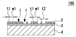
第3の実施形態の夜光性装飾物160の特徴は、同一の開口部内でその幅が異なっている点である。すなわち、装飾部材2に形成された開口パターンにおいて、帯状の狭い開口部1を略規則的に配列し、同一の開口部1に狭い開口幅t1と広い開口幅t2とを設けることで、同一領域内に光透過率が異なる領域を有するので、発光の明暗差による文字、記号、形状等を描いている。夜光性装飾物160の他の基本的な構成は、夜光性装飾物155と同様であるので、同一要素には同一符号を付し、重複する説明は省略する。   The feature of the luminous ornament 160 of the third embodiment is that the width is different in the same opening. That is, in the opening pattern formed in the decorative member 2, the band-like narrow openings 1 are arranged almost regularly, and the same opening 1 is provided with a narrow opening width t 1 and a wide opening width t 2. Since there are regions having different light transmittances, characters, symbols, shapes, etc. are drawn due to the difference in brightness of light emission. Since the other basic configuration of the luminescent ornament 160 is the same as that of the luminescent ornament 155, the same elements are denoted by the same reference numerals, and redundant description is omitted.

図3A、図3Bにおいて、夜光性装飾物160に装飾部材2が視認側に形成されている
。装飾部材2には開口パターンが形成されており、複数の帯状の開口部1が狭い開口幅t1で略等間隔に整列している。また、装飾部材2と基材4に挟持された空間には夜光性部材3が板状に所定の厚みに形成されている。一部の開口部1には部分的に広い開口幅t2が形成されており全体として発光部9を形成している。ここで、狭い開口部1の開口幅t1及び広い開口部1の開口幅t2は、ともに約3μm〜15.5μmに設定されている。尚、本実施形態では数字の「4」を発光表示する例として示している。
In FIG. 3A and FIG. 3B, the decoration member 2 is formed in the luminous decoration 160 on the visual recognition side. An opening pattern is formed in the decorative member 2, and a plurality of strip-like openings 1 are aligned at substantially equal intervals with a narrow opening width t <b> 1. In addition, a luminous member 3 is formed in a plate shape with a predetermined thickness in a space sandwiched between the decorative member 2 and the base material 4. Some of the openings 1 are partially formed with a wide opening width t2, and the light emitting section 9 is formed as a whole. Here, the opening width t1 of the narrow opening 1 and the opening width t2 of the wide opening 1 are both set to about 3 μm to 15.5 μm. In the present embodiment, the numeral “4” is shown as an example of light emission display.

このように、夜光性装飾物160は、各帯状の狭い開口部に、部分的に広い開口部を設けることによって、暗所では狭い開口部t1では暗く発光し、広い開口部t2では明るく発光するので、発光部9に明暗差を形成することができる。また明所では、装飾部材2に形成された開口パターンは視認し難いので金属感を得られ、夜光性部材に特有の白緑色系の色味を目立たなくすることができる。これにより、暗所では文字、記号、形状等を描くことができるので明所とは異なる趣のある視認性及び装飾性を付与した夜光性装飾物を提供することができる。また明所では、金属感のある視認性及び装飾性を備えるとともに、夜光性部材に特有の白緑色系の色味を目立たなくした夜光性装飾物を提供することができる。   As described above, the luminous ornament 160 is provided with a wide opening part in each band-like narrow opening, so that the narrow opening t1 emits light in the dark and the wide opening t2 emits light brightly. Therefore, a light / dark difference can be formed in the light emitting portion 9. In the bright place, the opening pattern formed in the decorative member 2 is difficult to visually recognize, so that a metallic feeling can be obtained, and the white-green color characteristic of the luminescent member can be made inconspicuous. Thereby, since a character, a symbol, a shape, etc. can be drawn in a dark place, the nocturnal decoration which provided the attractive visibility and decoration which differ from a bright place can be provided. Further, in a bright place, it is possible to provide a luminescent ornament that has a visibility and decoration with a metallic feeling, and that does not make the white-green color characteristic of the luminescent member inconspicuous.

尚、夜光性装飾物160は、数字の「4」に発光する例を説明したが、これに限定されず他の文字、記号、他の自由な形状でもよい。また、夜光性装飾物160の外形形状は矩形状で説明したがこれに限定されず、多角形、円形等でもよい。また、装飾部材2の開口パターンにおいて、文字等を形成する広い開口部に対して狭い開口部を規則的に混在させることによって開口パターンを平均化できるので、明所では開口パターンをより視認し難くする上で効果的である。また、狭い開口幅t1を約3μmより小さくすることにより、明暗差をさらに大きくして文字等を際立たせることができる。これらの効果は、以下に説明する他の実施形態においても同様に得ることができる。   In addition, although the example in which the nocturnal decoration 160 light-emits number "4" was demonstrated, it is not limited to this, Another character, a symbol, and another free shape may be sufficient. Moreover, although the external shape of the nocturnal ornament 160 was demonstrated with the rectangular shape, it is not limited to this, A polygon, a circle | round | yen, etc. may be sufficient. Further, in the opening pattern of the decorative member 2, the opening pattern can be averaged by regularly mixing the narrow opening with the wide opening forming the character or the like, so that it is more difficult to visually recognize the opening pattern in a bright place. It is effective in doing. Further, by making the narrow opening width t1 smaller than about 3 μm, it is possible to further increase the contrast between light and dark and make the characters stand out. These effects can be similarly obtained in other embodiments described below.

[第4の実施形態の説明:図4A、図4B]
次に、図4A、図4Bを用いて第4の実施形態である夜光性装飾物165を説明する。図4Aは夜光性装飾物165の平面図を示し、図4Bはその要部のD−D’断面を示す。
[Explanation of Fourth Embodiment: FIGS. 4A and 4B]
Next, the luminous decoration 165 which is 4th Embodiment is demonstrated using FIG. 4A and FIG. 4B. 4A shows a plan view of the luminous ornament 165, and FIG. 4B shows a DD ′ cross section of the main part thereof.

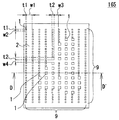
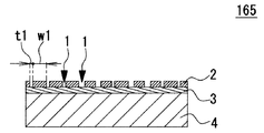
第4の実施形態の夜光性装飾物165の特徴は、装飾部材2に形成された開口パターンにおいて、狭い幅のドット状の角孔を略規則的に配列し、部分的に広い幅のドット状の角孔を配置することで同一領域内に光透過率が異なる領域を有するので、発光の明暗差による文字、記号等を描いた点である。夜光性装飾物165の他の基本的な構成は、夜光性装飾物160と同様であるので、同一要素には同一符号を付し、重複する説明は省略する。   The luminous decoration 165 of the fourth embodiment is characterized in that in the opening pattern formed in the decorative member 2, dot-shaped square holes with a narrow width are arranged almost regularly, and a dot shape with a partially wide width is formed. By arranging the square holes, there are regions having different light transmittances in the same region, so that characters, symbols, etc. are drawn due to the difference in brightness of light emission. Since the other basic configuration of the luminescent ornament 165 is the same as that of the luminescent ornament 160, the same components are denoted by the same reference numerals, and redundant description is omitted.

図4A、図4Bにおいて、夜光性装飾物165には装飾部材2が視認側に形成されている。装飾部材2には開口パターンが形成されており、複数のドット状の角孔が開口部1として配置されている。狭い開口幅(t1×t1)の開口部1は、横方向に装飾部材幅w1及び縦方向に装飾部材幅w2で略等間隔に整列している。また、広い開口幅(t2×t2)の開口部1は、横方向に装飾部材幅w3及び縦方向に装飾部材幅w4で配置されている。これらの狭い開口部1と広い開口部1は、全体として発光部9を形成している。ここで、狭い開口部1の開口幅t1及び広い開口部1の開口幅t2は、ともに約3μm〜15.5μmに設定されている。尚、本実施形態では数字の「4」を発光表示する例として示している。   In FIG. 4A and FIG. 4B, the decorative member 2 is formed on the viewing side in the luminous ornament 165. An opening pattern is formed in the decorative member 2, and a plurality of dot-shaped square holes are arranged as the opening 1. The openings 1 having a narrow opening width (t1 × t1) are aligned at substantially equal intervals with a decorative member width w1 in the horizontal direction and a decorative member width w2 in the vertical direction. The opening 1 having a wide opening width (t2 × t2) is arranged with a decorative member width w3 in the horizontal direction and a decorative member width w4 in the vertical direction. The narrow opening 1 and the wide opening 1 form a light emitting part 9 as a whole. Here, the opening width t1 of the narrow opening 1 and the opening width t2 of the wide opening 1 are both set to about 3 μm to 15.5 μm. In the present embodiment, the numeral “4” is shown as an example of light emission display.

このように、夜光性装飾物165の開口パターンは、前述した夜光性装飾物160と比較して帯状とドット状の違いはあるものの、暗所で発光表現する絵柄の形状に対して、開口部1の幅を変えることによって発光部9に明暗差を形成することができる。これにより
、夜光性装飾物165は、暗所では狭い開口幅t1の角孔では暗く発光し、広い開口幅t2の角孔では明るく発光するので明暗差を用いて文字、記号、形状等の複雑な絵柄を描くことができる。尚、開口部1を角孔として説明したが、異形の角孔、丸孔等他のどのような形状の開口でもよい。
As described above, the opening pattern of the luminous ornament 165 is different from the luminous ornament 160 described above in the band shape and the dot shape, but with respect to the shape of the pattern expressing the light emission in the dark place. By changing the width of 1, a light / dark difference can be formed in the light emitting portion 9. As a result, the nocturnal ornament 165 emits dark light in a square hole with a narrow opening width t1 in a dark place, and brightly emits light in a square hole with a wide opening width t2. Can draw a simple pattern. In addition, although the opening part 1 was demonstrated as a square hole, opening of what kind of shapes, such as an irregular-shaped square hole and a round hole, may be sufficient.

また、帯状の開口部1よりもドット状の開口部1のほうが開口部1を小さくすることができ、明所で目視によって開口部1を認識し難い大きさに留めておくことができる。また帯状の開口部1で構成した場合よりも、明所で、より金属感のある装飾物として認識され、暗所では、開口部1の幅によって夜光性部材3の発光に明暗差を作り出すことで様々な絵柄を表現することができる。   Further, the dot-shaped opening 1 can be made smaller than the band-shaped opening 1, and the opening 1 can be kept in a size that is difficult to recognize visually in a bright place. Moreover, it is recognized as a decoration with a metallic feeling in a bright place, compared with the case where it is constituted by a band-shaped opening 1, and in the dark place, a difference in brightness is created in the light emission of the luminous member 3 by the width of the opening 1. You can express a variety of patterns.

図4A及び図4Bを用いて説明した第4の実施形態を実施することにより、暗所でドット絵状の発光絵柄を表現することができ、さらに多彩な発光表現が可能となる。   By implementing the fourth embodiment described with reference to FIGS. 4A and 4B, it is possible to express a dot-like light-emission pattern in a dark place, and a variety of light-emission expressions are possible.

[第4の実施形態の変形例の説明:図4C]
図4Cを用いて第4の実施形態の変形例の一例である夜光性装飾物166を説明する。図4Cは夜光性装飾物166の平面図を示している。
[Description of Modified Example of Fourth Embodiment: FIG. 4C]
A luminous ornament 166, which is an example of a modification of the fourth embodiment, will be described with reference to FIG. 4C. FIG. 4C shows a plan view of the luminous ornament 166.

第4の実施形態の変形例である夜光性装飾物166の特徴は、装飾部材2に形成された開口パターンにおいて、複数の異なる幅の角孔を略規則的に配列して同一領域内に光透過率が異なる領域を形成して、暗所での発光の明暗差に階調を付与することよって立体的な球体図形を描いた点である。図4Cに示す黒い領域が装飾部材2を示し、白い領域が開口部1を示している。夜光性装飾物166の他の基本的な構成は、夜光性装飾物165と同様であるので、同一要素には同一符号を付し、重複する説明は省略する。   The feature of the luminous ornament 166, which is a modification of the fourth embodiment, is that the opening pattern formed in the decorative member 2 has a plurality of square holes with different widths arranged in a regular manner so that the light is within the same region. This is a point in which a three-dimensional spherical figure is drawn by forming regions having different transmittances and adding gradation to the difference in brightness of light emission in a dark place. The black area shown in FIG. 4C shows the decorative member 2, and the white area shows the opening 1. Since the other basic configuration of the luminous ornament 166 is the same as that of the luminous ornament 165, the same elements are denoted by the same reference numerals, and redundant description is omitted.

図4Cにおいて、夜光性装飾物166には装飾部材2が視認側に形成されている。装飾部材2には開口パターンが形成されており、複数の異なる幅のドット状の角孔が開口部1として配置されている。複数の異なる幅の開口部1について便宜的に、一番大きい角孔を開口部A、二番目に大きい角孔を開口部B、三番目に大きい角孔を開口部C、一番小さい角孔を開口部Dとする。   In FIG. 4C, the decorative member 2 is formed on the viewing side on the luminous ornament 166. An opening pattern is formed in the decorative member 2, and a plurality of dot-shaped square holes having different widths are arranged as the opening 1. For convenience, the largest square hole is the opening A, the second largest square hole is the opening B, the third largest square hole is the opening C, and the smallest square hole. Is the opening D.

開口部1を縦に4個、横に4個配置した計16個をドット絵の1個のドット(画素)1aとして構成し、立体的な球体を表現するように開口部Aから開口部Dを配置している。具体的には、球体が一番明るくなるハイライト部分に開口部Aを配置し、開口部Aの周辺に開口部Bを配置し、開口部Bの周囲に開口部Cを配置し、球体の一番暗くなる部分に開口部Dを配置するようにして立体的な球体を表現している。さらに開口部1を設けない領域を球体の輪郭部分に設け、その外側に開口部Aを配置することで球体の輪郭を明確にしている。   A total of 16 openings 1 arranged 4 vertically and 4 horizontally are configured as one dot (pixel) 1a of a dot picture, and the opening A to the opening D so as to represent a three-dimensional sphere. Is arranged. Specifically, the opening A is arranged in the highlight portion where the sphere is brightest, the opening B is arranged around the opening A, the opening C is arranged around the opening B, and A three-dimensional sphere is expressed by arranging the opening D in the darkest part. Furthermore, the area | region which does not provide the opening part 1 is provided in the outline part of a sphere, and the outline of a sphere is clarified by arrange | positioning the opening part A on the outer side.

このように、夜光性装飾物166の暗所での発光をドット絵柄として表現する際に、ドット(画素)1aを複数の開口部1によって構成し、開口部1を複数の異なる幅で構成することによって多階調表示が可能となり、第4の実施形態よりもさらに多彩な絵柄の表現が可能となる。複数の開口部1によってドット(画素)1aを構成することで、目視で開口部1を認識し難い大きさに止めておくことができ、ドット(画素)1aを1つの開口部1で構成した場合よりも、明所で、より金属感のある装飾物として認識され、暗所では、開口部1の幅によって夜光性部材3の発光に明暗差を作り出すことで様々な絵柄を表現することができる。図4Cに示す球体の例は、あくまでも一例であり、絵柄については文字、図形など様々な表現に適用することが可能である。   In this way, when the light emission in the dark place of the luminous ornament 166 is expressed as a dot pattern, the dot (pixel) 1a is constituted by the plurality of openings 1, and the opening 1 is constituted by a plurality of different widths. As a result, multi-gradation display is possible, and a variety of patterns can be expressed more than in the fourth embodiment. By configuring the dots (pixels) 1a with the plurality of openings 1, it is possible to keep the size of the openings 1 difficult to recognize visually, and the dots (pixels) 1a are configured with a single opening 1. It can be recognized as a more metallic decoration in the bright place than in the case. In the dark place, various patterns can be expressed by creating a light and dark difference in the light emission of the luminous member 3 depending on the width of the opening 1. it can. The example of the sphere shown in FIG. 4C is merely an example, and the pattern can be applied to various expressions such as characters and figures.

夜光性装飾物166の開口パターンは、第4の実施形態で説明した夜光性装飾物165
と比較して夜光性装飾物166の暗所での発光をドット絵として表現する際に、ドット(画素)1aを複数の開口部1によって構成し、開口部1の幅を4種類とさらに増やすことで多階調表示を可能とした点が異なっているが、開口部1の形状は、第4の実施形態と同様に、異形の角孔、丸孔等他のどのような形状の開口でもよい。
The opening pattern of the luminous ornament 166 is the luminous ornament 165 described in the fourth embodiment.
When the light emission in the dark place of the luminous ornament 166 is expressed as a dot picture, the dot (pixel) 1a is constituted by a plurality of openings 1, and the width of the opening 1 is further increased to four types. However, the shape of the opening 1 can be any other shape such as an irregularly shaped square hole or a round hole, as in the fourth embodiment. Good.

また、上記では、ドット(画素)1aを同一幅の開口部1を4×4に配置した例について説明したが、ドット(画素)1a内の開口部1の幅が異なっていてもよく、ドット(画素)1a内の開口部1の数も表現したい絵柄の大きさやドット(画素)1aの数によって適宜設定することが可能である。   In the above description, an example in which the openings 1 having the same width as the dots (pixels) 1a are arranged in 4 × 4 has been described. However, the widths of the openings 1 in the dots (pixels) 1a may be different. The number of openings 1 in the (pixel) 1a can also be set as appropriate depending on the size of the pattern to be expressed and the number of dots (pixels) 1a.

[第5の実施形態の説明:図5A、図5B]
次に、図5A、図5Bを用いて第5の実施形態の夜光性装飾物170を説明する。図5Aは夜光性装飾物170の平面図を示し、図5Bはその要部のE−E’断面を示す。
[Explanation of Fifth Embodiment: FIGS. 5A and 5B]
Next, the luminous decoration 170 of 5th Embodiment is demonstrated using FIG. 5A and FIG. 5B. FIG. 5A shows a plan view of the luminous decoration 170, and FIG. 5B shows an EE ′ cross section of the main part thereof.

第5の実施形態の夜光性装飾物170の特徴は、装飾部材2に形成された開口パターンにおいて、狭いドット状の角孔の開口部1を規則的に配列し、部分的に狭いドット状の角孔の配置密度を変えることで同一領域内に光透過率が異なる領域を有するので、発光の明暗差を形成して、文字、記号等を描いた点である。夜光性装飾物170の他の基本的な構成は、夜光性装飾物165と同様であるので、同一要素には同一符号を付し、重複する説明は省略する。   The feature of the luminous ornament 170 of the fifth embodiment is that the openings 1 of the narrow dot-shaped square holes are regularly arranged in the opening pattern formed in the decorative member 2, and the partially narrow dot-shaped Since there are regions having different light transmittances in the same region by changing the arrangement density of the square holes, a difference in brightness of light emission is formed and characters, symbols, and the like are drawn. Since the other basic configuration of the luminescent ornament 170 is the same as that of the luminescent ornament 165, the same elements are denoted by the same reference numerals, and redundant description is omitted.

図5A、図5Bにおいて、夜光性装飾物170は装飾部材2が視認側に形成されている。装飾部材2には開口パターンが形成されており、複数の角孔状の開口部1が規則的に配列されている。開口部1は開口幅(t1×t1)で形成されていて、横方向に装飾部材幅w1及び縦方向に装飾部材幅w2で略等間隔に整列している。一方、部分的に開口部1は横方向に狭いピッチの装飾部材幅w3及び縦方向に狭いピッチの装飾部材幅w4で略等間隔に配置されている。これらのw1、w2で整列した開口部1とw3、w4で整列した開口部1によって発光部9を形成している。ここで、開口部1の開口幅(t1×t1)は約3μm〜15.5μmに設定されている。尚、本実施形態では数字の「4」を発光表示する例として示している。   In FIG. 5A and FIG. 5B, as for the nocturnal ornament 170, the decoration member 2 is formed in the visual recognition side. The decorative member 2 is formed with an opening pattern, and a plurality of square hole-shaped openings 1 are regularly arranged. The openings 1 are formed with an opening width (t1 × t1), and are aligned at substantially equal intervals with a decorative member width w1 in the horizontal direction and a decorative member width w2 in the vertical direction. On the other hand, the openings 1 are partially arranged at substantially equal intervals with a decorative member width w3 having a narrow pitch in the horizontal direction and a decorative member width w4 having a narrow pitch in the vertical direction. The light emitting portion 9 is formed by the opening 1 aligned with w1 and w2 and the opening 1 aligned with w3 and w4. Here, the opening width (t1 × t1) of the opening 1 is set to about 3 μm to 15.5 μm. In the present embodiment, the numeral “4” is shown as an example of light emission display.

このように、夜光性装飾物170は、ドット状の開口部1の配置密度を変えることによって、暗所では開口部のピッチが粗い部分では暗く発光し、ピッチが密の部分では明るく発光して発光部9に明暗差を形成することができる。また明所では、装飾部材2に形成された開口パターンは視認し難いので金属感を得られる。これにより、夜光性装飾物170は、暗所では文字、記号、形状等の発光絵柄を認識することができるので明所とは異なる趣のある視認性及び装飾性を付与した夜光性装飾物170を提供することができる。また明所では、金属感のある視認性及び装飾性を備えるとともに夜光性部材3に特有の白緑色系の色味を目立たなくした夜光性装飾物170を提供することができる。尚、開口部1を角孔として説明したが、丸孔等他のどのような形状の開口でもよい。   As described above, the luminous decoration 170 changes the arrangement density of the dot-shaped openings 1 to emit light darkly in a dark portion where the pitch of the openings is rough and brightly emit light where the pitch is dense. A light / dark difference can be formed in the light emitting portion 9. In a bright place, the opening pattern formed in the decorative member 2 is difficult to visually recognize, so that a metallic feeling can be obtained. As a result, the luminous decoration 170 can recognize light-emitting patterns such as characters, symbols, and shapes in the dark, and thus has a gorgeous visibility and decorativeness different from the bright place. Can be provided. Further, in the bright place, it is possible to provide a luminescent ornament 170 having a metal-like visibility and a decorative property and in which the white-green color characteristic of the luminescent member 3 is inconspicuous. Although the opening 1 has been described as a square hole, it may be any other shape such as a round hole.

[第1の実施形態の製造工程の説明:図6A〜図6D]
次に、本発明の夜光性装飾物の製造方法について簡単に説明する。図6A〜図6Dは、夜光性装飾物の製造工程S1〜S4を示す断面図である。
[Description of Manufacturing Process of First Embodiment: FIGS. 6A to 6D]
Next, the manufacturing method of the luminous ornament of this invention is demonstrated easily. Drawing 6A-Drawing 6D are sectional views showing manufacturing process S1-S4 of a luminous decoration.

まず、図6Aに示す製造工程S1において、板状の夜光性部材3の表面に例えば、金、プラチナ、クロム、アルミニウムなどを真空蒸着やスパッタリングなどの方法によって、所定の厚みに装飾部材2を形成する。次に、図6Bに示す製造工程S2において、装飾部材2の表面に所定の開口パターンを形成するためのレジスト11を形成する。次に、図6Cに示す製造工程S3において、レジスト11が形成されていない領域を湿式又は乾式で
エッチングすることで装飾部材2に開口パターンを形成する。次に、図6Dに示す製造工程S4において、レジスト11を除去する。
First, in the manufacturing step S1 shown in FIG. 6A, the decorative member 2 is formed on the surface of the plate-like luminous member 3 to a predetermined thickness by, for example, vacuum deposition or sputtering using gold, platinum, chromium, aluminum or the like. To do. Next, in the manufacturing step S2 shown in FIG. 6B, a resist 11 for forming a predetermined opening pattern on the surface of the decorative member 2 is formed. Next, in the manufacturing process S3 shown in FIG. 6C, an opening pattern is formed in the decorative member 2 by etching a region where the resist 11 is not formed by wet or dry processing. Next, in the manufacturing process S4 shown in FIG. 6D, the resist 11 is removed.

これにより、所定の開口部の幅を有し所定の開口パターンを有する装飾部材2が夜光性部材3の表面に形成されて夜光性装飾物150が完成する。尚、前述した夜光性部材3を基材4に積層する構成(夜光性装飾物155、160、165、170参照)においても、主要な工程は同様であり同様の製造方法を用いることができる。   As a result, the decorative member 2 having a predetermined opening width and a predetermined opening pattern is formed on the surface of the luminous member 3, and the luminous ornament 150 is completed. In addition, also in the structure which laminates the luminous member 3 mentioned above on the base material 4 (refer to luminous decorations 155, 160, 165, 170), the main processes are the same and the same manufacturing method can be used.

[第1の実施形態における他の構成例の説明:図7A、図7B、図7C]
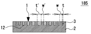
次に、基本形である第1の実施形態に対して他の3つの構成例について簡単に説明する。図7Aは、夜光性装飾物180の断面図を示し、図7Bは、夜光性装飾物185の断面図を示し、図7Cは、夜光性装飾物190の断面図を示す。尚、3つの構成例は夜光性部材3と装飾部材2の混在する比率は前述の夜光性装飾物150と同様になっている。
[Description of Other Configuration Examples in First Embodiment: FIGS. 7A, 7B, and 7C]
Next, other three configuration examples will be briefly described with respect to the first embodiment which is a basic form. 7A shows a cross-sectional view of the luminescent ornament 180, FIG. 7B shows a cross-sectional view of the luminescent ornament 185, and FIG. 7C shows a cross-sectional view of the luminescent ornament 190. In the three configuration examples, the ratio of the luminous member 3 and the decorative member 2 is the same as that of the luminous ornament 150 described above.

[夜光性装飾物180の説明:図7A]
夜光性装飾物180の特徴は、基材4に夜光性部材3を配置するための凹部12を設け、凹部12に夜光性部材3を充填形成し、基材4上に所定の開口パターンを有する装飾部材2を積層形成した点である。夜光性装飾物180の他の基本的な構成は、第1から第5の実施形態で説明した夜光性装飾物と同様であるので、同一要素には同一符号を付し、重複する説明は省略する。
[Description of Luminous Decoration 180: FIG. 7A]
The feature of the luminous decoration 180 is that the concave portion 12 for arranging the luminous member 3 is provided on the base material 4, the luminous member 3 is filled in the concave portion 12, and a predetermined opening pattern is provided on the base material 4. The decorative member 2 is laminated. Since the other basic configuration of the luminous ornament 180 is the same as that of the luminous ornament described in the first to fifth embodiments, the same elements are denoted by the same reference numerals, and redundant description is omitted. To do.

図7Aにおいて、夜光性装飾物180は、基材4に凹部12が所定の間隔及び所定の深さで複数形成されていて、凹部12には夜光性部材3が充填形成されている。また、基材4及び夜光性部材3の上面には装飾部材2が所定の厚みで積層形成され所定の開口パターンが形成されている。開口パターンは開口部1の幅t〜t’、装飾部材2の幅w〜w’であり、基材4に充填形成された夜光性部材3のピッチと装飾部材2に形成された開口部1のピッチは略同一になっている。このように夜光性装飾物180は、基材4の一部の領域に夜光性部材3を形成する構造であるので夜光性部材3の使用量を減らすことができ経済的である。他の基本的な動作及び効果は第1から第5の実施形態で説明した夜光性装飾物と同様であるので重複する説明は省略する。尚、装飾部材2の1つの開口部に対して1つの凹部12を形成するとしたが、それに限定されず、装飾部材2の複数の開口部にまたがって凹部12を設ける構成としてもよい。   In FIG. 7A, in the luminous ornament 180, a plurality of concave portions 12 are formed on the base material 4 at a predetermined interval and a predetermined depth, and the luminous member 3 is filled in the concave portions 12. Further, the decorative member 2 is laminated and formed with a predetermined thickness on the upper surface of the base material 4 and the luminous member 3 to form a predetermined opening pattern. The opening pattern has a width t to t ′ of the opening 1 and a width w to w ′ of the decorative member 2, and the pitch of the luminous member 3 filled in the base material 4 and the opening 1 formed in the decorative member 2. Are substantially the same pitch. Thus, since the luminous decoration 180 is a structure which forms the luminous member 3 in the one part area | region of the base material 4, the usage-amount of the luminous member 3 can be reduced and it is economical. Other basic operations and effects are the same as those of the luminous ornament described in the first to fifth embodiments, and thus redundant description is omitted. In addition, although the one recessed part 12 was formed with respect to one opening part of the decoration member 2, it is not limited to it, It is good also as a structure which provides the recessed part 12 ranging over the several opening part of the decoration member 2. FIG.

[夜光性装飾物185の説明:図7B]
夜光性装飾物185の特徴は、装飾部材2に夜光性部材3を配置するための凹部12を設けるとともに、所定の開口パターンを形成し、凹部12に夜光性部材3を充填形成した点である。夜光性装飾物185の他の基本的な構成は、第1から第5の実施形態で説明した夜光性装飾物と同様であるので、同一要素には同一符号を付し、重複する説明は省略する。
[Description of nocturnal ornament 185: FIG. 7B]
The feature of the luminous decoration 185 is that the decorative member 2 is provided with the recess 12 for arranging the luminous member 3, a predetermined opening pattern is formed, and the concave member 12 is filled with the luminous member 3. . Since the other basic configuration of the luminous ornament 185 is the same as that of the luminous ornament described in the first to fifth embodiments, the same elements are denoted by the same reference numerals, and redundant description is omitted. To do.

図7Bにおいて、夜光性装飾物185は、装飾部材2の上面(視認面側)に複数の凹部12(開口部1)が所定の間隔及び所定の深さで複数形成されることで開口パターンが形成されている。凹部12には夜光性部材3が充填形成されている。また、各凹部12は開口幅がt〜t’、装飾部材幅がw〜w’になっている。これにより夜光性装飾物185は、装飾部材2に凹部12を設けて、直接夜光性部材3を充填形成する構造になっている。このような構造により発光部の製造が容易である。他の基本的な動作及び効果は第1から第5の実施形態で説明した夜光性装飾物と同様であるので重複する説明は省略する。   In FIG. 7B, the luminous decoration 185 has an opening pattern formed by forming a plurality of recesses 12 (openings 1) at a predetermined interval and a predetermined depth on the upper surface (viewing surface side) of the decorative member 2. Is formed. The recess 12 is filled with the luminous member 3. Each recess 12 has an opening width t to t ′ and a decorative member width w to w ′. Thereby, the luminous ornament 185 has a structure in which the concave member 12 is provided in the decorative member 2 and the luminous member 3 is directly filled. With such a structure, the light emitting part can be easily manufactured. Other basic operations and effects are the same as those of the luminous ornament described in the first to fifth embodiments, and thus redundant description is omitted.

[夜光性装飾物190の説明:図7C]
夜光性装飾物190の特徴は、基材4上に装飾部材2による凸部を形成するとともに夜
光性部材3を配置するための凹部12を形成し、凹部12に夜光性部材3を充填形成した点である。夜光性装飾物190の他の基本的な構成は、第1から第5の実施形態で説明した夜光性装飾物と同様であるので、同一要素には同一符号を付し、重複する説明は省略する。
[Description of nocturnal ornament 190: FIG. 7C]
The feature of the luminous decoration 190 is that the convex portion by the decorative member 2 is formed on the substrate 4 and the concave portion 12 for arranging the luminous member 3 is formed, and the concave portion 12 is filled with the luminous member 3. Is a point. The other basic configuration of the luminous ornament 190 is the same as that of the luminous ornament described in the first to fifth embodiments. Therefore, the same components are denoted by the same reference numerals, and redundant description is omitted. To do.

図7Cにおいて、基材4の上面には凸状に装飾部材2が所定の高さ及び所定の間隔でパターン形成されている。各装飾部材2の間に形成された凹部12は、開口幅t〜t’、装飾部材2の幅w〜w’であり、夜光性部材3が充填形成されている。このように夜光性装飾物190は、基材4の上面に直接、装飾部材2を設ける構造であるので剛性と装飾性を両立することができる。他の基本的な動作及び効果は第1から第5の実施形態で説明した夜光性装飾物と同様であるので重複する説明は省略する。   In FIG. 7C, the decorative member 2 is formed in a pattern with a predetermined height and a predetermined interval on the upper surface of the base material 4. The recess 12 formed between the decorative members 2 has an opening width t to t ′ and a width w to w ′ of the decorative member 2, and is filled with the luminous member 3. Thus, since the nocturnal decoration 190 is a structure which provides the decoration member 2 directly on the upper surface of the base material 4, it can be compatible in rigidity and decoration. Other basic operations and effects are the same as those of the luminous ornament described in the first to fifth embodiments, and thus redundant description is omitted.

[第6の実施形態(装飾部材の厚みを変える例)の説明:図8A]
次に、図8Aを用いて第6の実施形態の夜光性装飾物200を説明する。図8Aは、夜光性装飾物200の断面図を示す。尚、平面図は省略し、以下に説明する夜光性装飾物205〜210についても同様に省略する。
[Description of Sixth Embodiment (Example of Changing the Thickness of a Decorative Member): FIG. 8A]
Next, the luminous ornament 200 of 6th Embodiment is demonstrated using FIG. 8A. FIG. 8A shows a cross-sectional view of the luminous decoration 200. Note that the plan view is omitted, and the luminous decorations 205 to 210 described below are similarly omitted.

第6の実施形態の夜光性装飾物200の特徴は、夜光性部材3の表面に、金属膜又は樹脂中に着色粒子を含有した着色層で形成した装飾部材2を設け、同一領域内で装飾部材2の厚みを変えることにより光透過率が異なる領域を備えた点である。   A feature of the luminous ornament 200 of the sixth embodiment is that a decorative member 2 formed of a colored layer containing colored particles in a metal film or resin is provided on the surface of the luminous member 3 and decorated in the same region. This is the point that a region having different light transmittance is provided by changing the thickness of the member 2.

[構成の説明]
図8Aにおいて、夜光性装飾物200は、夜光性部材3の上面(視認側)に例えば着色粒子を含有したエポキシ樹脂やアクリル樹脂などで装飾部材2が形成されている。装飾部材2の上面側は図1Aにて説明した夜光性装飾物150と同様の矩形状の平面を有している。また、装飾部材2の下面側は内部に階段状の凹部を有しており段毎に装飾部材2の厚みが変化している。また、階段状の装飾部材2は、図面手前側から奥行き方向に向かって帯状に形成されている。階段状の装飾部材2の各部の厚みはそれぞれ所定の厚みになっているが、樹脂中には、例えば金属粒子のアルミや顔料の二酸化チタン等の着色粒子が均一に分散して配合された着色層になっているので、厚い部分は光透過率が低く、薄い部分は光透過率が高くなっている。また、凹部には空間を充填するように透明部材5が形成されていてもよい。上記説明では、装飾部材2として、樹脂中に着色粒子を含有した着色層を例として説明したが、金属膜の厚みを異ならせることでも同様に光透過率が異なる領域を形成することができる。
装飾部材2として着色粒子を含有したエポキシ樹脂やアクリル樹脂を用いる場合は、厚みを0.1μm〜数10μm程度とし、装飾部材2として金属膜を用いる場合は、厚みを10nm〜数100nm程度として所定の厚みを選択する。
[Description of configuration]
In FIG. 8A, in the luminous decoration 200, the decorative member 2 is formed on the upper surface (viewing side) of the luminous member 3 with, for example, an epoxy resin or an acrylic resin containing colored particles. The upper surface side of the decorative member 2 has a rectangular plane similar to the luminous decoration 150 described in FIG. 1A. Moreover, the lower surface side of the decorative member 2 has a step-like recess inside, and the thickness of the decorative member 2 changes for each step. Further, the step-like decorative member 2 is formed in a band shape from the front side of the drawing toward the depth direction. The thickness of each part of the staircase-shaped decorative member 2 is a predetermined thickness, but in the resin, for example, colored particles such as aluminum of metal particles and titanium dioxide of pigment are uniformly dispersed and blended. Since it is a layer, the thick portion has low light transmittance, and the thin portion has high light transmittance. Moreover, the transparent member 5 may be formed in the recess so as to fill the space. In the above description, a colored layer containing colored particles in the resin has been described as an example of the decorative member 2. However, regions having different light transmittances can be formed by varying the thickness of the metal film.
When an epoxy resin or acrylic resin containing colored particles is used as the decorative member 2, the thickness is set to about 0.1 μm to several tens of μm. When a metal film is used as the decorative member 2, the thickness is set to about 10 nm to several hundreds of nm. Select the thickness.

[動作の説明]
夜光性装飾物200において、明所で外部光が装飾部材2を透過して蓄光された夜光性部材3は励起状態となり、暗所で外部光が遮断されると基底状態に戻る過程でゆっくり発光する。夜光性部材3の発光は装飾部材2の下面側から装飾部材2を透過するものと着色粒子に衝突して散乱するものとがある。装飾部材2において着色粒子との衝突回数が多い厚い部分は光透過率が低いので暗く発光し、衝突回数が少ない薄い部分は光透過率が高いので明るく発光する。これにより、暗所では装飾部材2の上面側から視認すると帯状に中央部が明るく両端側に向けて徐々に暗くなるような明暗差を作りだすことができる(後述する図9A参照)。また、所定の着色粒子を配合した樹脂を用いることで、明所では文字、形状、絵柄などに所望の金属感や色彩を有することができる。例えば、金属粒子のアルミ粒子を用いれば銀色の金属感が得られ、顔料の二酸化チタンを用いれば白色が得られる。また、着色粒子の大きさを変えることによって風合いを変えてもよい。
[Description of operation]
In the nocturnal ornament 200, the nocturnal member 3 in which the external light passes through the decorative member 2 and is stored in the bright place is excited, and slowly emits light in the process of returning to the ground state when the external light is blocked in the dark place. To do. The luminous member 3 emits light that passes through the decorative member 2 from the lower surface side of the decorative member 2 and scatters by colliding with the colored particles. In the decorative member 2, the thick part where the number of collisions with the colored particles is large has low light transmittance and thus emits light darkly, and the thin part where the number of collisions is small has high light transmittance and emits brightly. As a result, in a dark place, when viewed from the upper surface side of the decorative member 2, it is possible to create a light-dark difference in which the central portion is bright and gradually darkens toward both ends when viewed from the top (see FIG. 9A described later). Further, by using a resin in which predetermined colored particles are blended, it is possible to have a desired metal feeling or color in characters, shapes, patterns, etc. in a bright place. For example, when aluminum particles of metal particles are used, a silver metal feeling can be obtained, and when titanium dioxide of pigment is used, white can be obtained. Further, the texture may be changed by changing the size of the colored particles.

[効果の説明]
夜光性装飾物200は、外部光を有効に利用する夜光性装飾物であって、暗所では同一領域内に帯状やドット状に夜光性部材の発光の明るい領域と暗い領域とを形成することができる。これにより、発光の明暗差によるグラデーション模様、文字、絵柄などを描くことができるので趣のある視認性及び装飾性を付与した夜光性装飾物を提供することができる。また、明所では所望の金属感や色彩を有する文字、形状、絵柄などを描くことができるとともに、夜光性部材に特有の白緑色系の色味を目立たなくした夜光性装飾物を提供することができる。また透明部材5は導光板として作用するので、明所では外部光を効率良く受光し、暗所では夜光性部材を効率良く発光させることができる。
[Description of effects]
The luminescent ornament 200 is a luminescent ornament that effectively uses external light, and in the dark place, a bright region and a dark region of light emission of the luminescent member are formed in the same region in a band shape or a dot shape. Can do. Thereby, since a gradation pattern, a character, a pattern, etc. by the light-emission brightness difference can be drawn, the nocturnal decoration which provided the glaring visibility and decoration property can be provided. Also, in a bright place, it is possible to draw letters, shapes, designs, etc. having a desired metallic feeling and color, and to provide a luminescent decoration that makes the white-green color characteristic of a luminescent member inconspicuous Can do. Further, since the transparent member 5 acts as a light guide plate, it can efficiently receive external light in a bright place and can efficiently emit a nocturnal member in a dark place.

尚、装飾部材2は、階段状に形成された夜光性部材3の上面に、樹脂層を例えばスクリーン印刷法やタンポ印刷法を用いて所定回数印刷することで形成することができる。尚、本例では装飾部材2は中央部が薄く両端部に向けて階段状に厚く形成されているが、特に限定するものではなく、例えば中央部が厚く両端部が薄い構造としてもよい。また、階段状としたが斜面状に形成してもよい。ここで、装飾部材2に用いる主な樹脂をあげておく。特に限定はしないがエポキシ樹脂、ウレタン樹脂、アクリル樹脂等である。また、装飾部材2に配合する主な着色粒子をあげておく。特に限定はしないが金属粒子を用いる場合は、例えばアルミ、真鍮、硫化亜鉛等である。また、顔料を用いる場合は、カーボンブラック、二酸化チタン、酸化鉄、黄鉛等である。尚、着色粒子に所定の顔料を用いることで、暗所では、発光の明暗差に加えて所望の色彩を得ることができる。   The decorative member 2 can be formed by printing a resin layer a predetermined number of times on the upper surface of the luminous member 3 formed in a step shape by using, for example, a screen printing method or a tampo printing method. In this example, the decorative member 2 has a thin central portion and is formed thick in a stepped shape toward both end portions. However, the present invention is not particularly limited. For example, the decorative member 2 may have a structure in which the central portion is thick and both end portions are thin. Further, although it is stepped, it may be formed in a slope shape. Here, main resins used for the decorative member 2 are listed. Although not specifically limited, it is an epoxy resin, a urethane resin, an acrylic resin, or the like. In addition, main colored particles to be blended in the decorative member 2 are listed. Although not particularly limited, when metal particles are used, for example, aluminum, brass, zinc sulfide and the like are used. Moreover, when using a pigment, they are carbon black, titanium dioxide, iron oxide, chrome lead, etc. In addition, by using a predetermined pigment for the colored particles, a desired color can be obtained in a dark place in addition to the difference in brightness of light emission.

[第6の実施形態における変形例の説明:図8B]
次に、図8Bを用いて第6の実施形態における変形例の夜光性装飾物205を説明する。図8Bは、夜光性装飾物205の断面図を示す。
[Explanation of Modification in Sixth Embodiment: FIG. 8B]
Next, the luminous decoration 205 of the modification in 6th Embodiment is demonstrated using FIG. 8B. FIG. 8B shows a cross-sectional view of the luminous decoration 205.

第6の実施形態における変形例である夜光性装飾物205の特徴は、前述した夜光性装飾物200と同様に、夜光性部材3の表面に、樹脂中に着色粒子を含有した着色層からなる装飾部材2を形成して、同一領域内に光透過率が異なる領域を備えたものであるが、夜光性装飾物200と異なるのは透明部材5に相当する空間には夜光性部材3が階段状に形成され充填されている点である。夜光性装飾物205の他の基本的な構成は、夜光性装飾物200と同様であるので、同一要素には同一符号を付し、重複する説明は省略する。   The feature of the luminous ornament 205, which is a modified example of the sixth embodiment, consists of a colored layer containing colored particles in the resin on the surface of the luminous member 3, like the luminous ornament 200 described above. The decorative member 2 is formed, and regions having different light transmittances are provided in the same region, but the luminous member 3 is different from the luminous ornament 200 in the space corresponding to the transparent member 5 where the luminous member 3 is a staircase. It is the point formed and filled in the shape. Since the other basic configuration of the luminescent ornament 205 is the same as that of the luminescent ornament 200, the same elements are denoted by the same reference numerals, and redundant description is omitted.

図8Bにおいて、夜光性部材205は、夜光性部材3の上面(視認側)に樹脂からなる装飾部材2が形成されている。また、装飾部材2の下面側は内部に階段状の凹部を有しており段毎に樹脂層の厚みが変化している。樹脂層の階段状の各部の厚みはそれぞれ所定の厚みになっているが、樹脂中には着色粒子が均一に分散して配合されているので、厚い部分は光透過率が低く、薄い部分は光透過率が高くなっている。また、装飾部材2の下面側の凹部には夜光性部材3が充填形成されているので夜光性部材3は中央付近の発光量を増すことができる。これにより、夜光性装飾物200と比較して暗所において中央部がより明るく発光するので発光の明暗差を拡大することができる。   In FIG. 8B, the luminous member 205 has the decorative member 2 made of resin on the upper surface (viewing side) of the luminous member 3. In addition, the lower surface side of the decorative member 2 has a step-like recess inside, and the thickness of the resin layer changes for each step. The thickness of each stepped part of the resin layer is a predetermined thickness, but since the colored particles are uniformly dispersed in the resin, the thick part has low light transmittance, and the thin part The light transmittance is high. Further, since the luminous member 3 is filled and formed in the concave portion on the lower surface side of the decorative member 2, the luminous member 3 can increase the light emission amount near the center. Thereby, compared with the nocturnal ornament 200, the central portion emits light more brightly in a dark place, so that the difference in light intensity can be increased.

[第7の実施形態(着色粒子の含有量を変える例)の説明:図8C]
次に、図8Cを用いて第7の実施形態の夜光性装飾物210を説明する。図8Cは、夜光性装飾物210の断面図を示す。
[Description of seventh embodiment (example of changing content of colored particles): FIG. 8C]
Next, the luminous decoration 210 of 7th Embodiment is demonstrated using FIG. 8C. FIG. 8C shows a cross-sectional view of the luminous decoration 210.

第7の実施形態の夜光性装飾物210の特徴は、夜光性部材3の表面に、樹脂中に着色粒子を含有した着色層からなる装飾部材2を形成して、同一領域内に光透過率が異なる領域を備えたものであるが、着色層は均一の厚みで複数の帯状の着色層から形成され、着色層は帯毎に着色粒子の含有量(密度)を変えて光透過率が異なる領域を形成した点である
。夜光性装飾物210の他の基本的な構成は、夜光性装飾物200と同様であるので、同一要素には同一符号を付し、重複する説明は省略する。
The feature of the luminous decoration 210 of the seventh embodiment is that the decorative member 2 composed of a colored layer containing colored particles in the resin is formed on the surface of the luminous member 3, and the light transmittance is within the same region. However, the colored layer is formed of a plurality of strip-shaped colored layers with a uniform thickness, and the colored layer has different light transmittance by changing the content (density) of colored particles for each strip. This is the point where the region is formed. Since the other basic configuration of the luminescent ornament 210 is the same as that of the luminescent ornament 200, the same elements are denoted by the same reference numerals, and redundant description is omitted.

図8Cにおいて、夜光性装飾物210は、夜光性部材3の上面(視認側)に樹脂からなる複数の帯状の装飾部材2が並列して同じ厚みに形成されている。ここで複数の帯状の装飾部材2の樹脂中の着色粒子はそれぞれ所定の含有率で配合され、例えば、中央部の装飾部材2の含有率が最も低く(低密度)、両端側の装飾部材2に向けて段階的に含有率が高く(高密度)なるように配合されている。これにより、光透過率が中央部から両端側に向けて段階的に低くなり明暗差を作ることができる(後述する図9A参照)。尚、着色粒子が持つ特有の色を用いて各帯状の装飾部材2に所定の着色を行うことで、明所において所望の色彩を有することができる。また、暗所において明暗差に加えて所望の色彩を得ることができる。尚、装飾部材2に配合する着色粒子の含有量や色の種類を多くする場合は、例えば、インクジェット方式を用いた着色層形成工程を採用することにより手番の短縮が可能である。   In FIG. 8C, the luminous decoration 210 has a plurality of strip-shaped decorative members 2 made of resin formed in parallel on the upper surface (viewing side) of the luminous member 3 to have the same thickness. Here, the colored particles in the resin of the plurality of strip-shaped decorative members 2 are respectively mixed at a predetermined content rate. For example, the content rate of the central decorative member 2 is the lowest (low density), and the decorative members 2 on both ends are provided. It is compounded so that the content rate becomes higher (high density) step by step. As a result, the light transmittance decreases stepwise from the central portion toward both ends, and a brightness difference can be created (see FIG. 9A described later). In addition, it can have a desired color in a bright place by performing predetermined coloring to each strip | belt-shaped decoration member 2 using the characteristic color which a colored particle has. In addition, a desired color can be obtained in addition to the light / dark difference in a dark place. In addition, when increasing content and the kind of color of the colored particle mix | blended with the decoration member 2, a shortening of a turn is possible by employ | adopting the colored layer formation process using an inkjet system, for example.

[第7の実施形態の暗所での表示例の説明:図9A]
次に、図9Aを用いて、例えば光透過率が異なる帯状の領域を有する装飾部材を備えた夜光性装飾物210の暗所における表示例を説明する。図9Aは、暗所において夜光性装飾物210を上面(視認側)から見た表示例である。便宜的に樹脂からなる装飾部材2において、一番光透過率が高い部分を領域A、二番目に光透過率が高い部分を領域B、三番目に光透過率が高い部分を領域C、一番光透過率が低い部分を領域Dとする。図9Aにおいて、中央部に領域Aを配置し、両端側に向けてそれぞれ領域B、領域C、領域Dを配置している。これにより、領域Aが最も明るく発光し、両端側に向けて領域B、領域C、領域Dの順に段階的に暗く発光するようにできる。これにより、帯状のグラデーション模様を描くことができる。尚、図8A〜図8Cを用いて説明した第6及び第7の実施形態は、同様のグラデーションを描くことができるが、それぞれの構成により明暗差は異なるので、用途に応じて適宜選択することができる。
[Description of Display Example in Dark Area of Seventh Embodiment: FIG. 9A]
Next, with reference to FIG. 9A, for example, a display example in the dark place of the nocturnal ornament 210 having a decorative member having a band-like region having different light transmittances will be described. FIG. 9A is a display example in which the luminous decoration 210 is viewed from the upper surface (viewing side) in a dark place. For convenience, in the decorative member 2 made of resin, the portion with the highest light transmittance is the region A, the portion with the second highest light transmittance is the region B, the portion with the third highest light transmittance is the region C, A portion having a low light transmittance is defined as a region D. In FIG. 9A, a region A is arranged at the center, and regions B, C, and D are arranged toward both ends, respectively. As a result, the region A emits the brightest light, and the regions B, C, and D can emit light in a stepwise manner toward both ends. Thereby, a belt-like gradation pattern can be drawn. The sixth and seventh embodiments described with reference to FIGS. 8A to 8C can draw the same gradation. However, the difference in brightness differs depending on the configuration, and therefore it is selected as appropriate according to the application. Can do.

[第7の実施形態の暗所での立体形状の表示例の説明:図9B]
次に、図9Bを用いて、夜光性装飾物210を光透過率が異なる領域を有する構成とした場合の夜光性装飾物211の暗所における立体形状の表示例を説明する。図9Bは、暗所において夜光性装飾物211を上面(視認側)から見た表示例であり「立方体」を描いたものである。便宜的に樹脂からなる装飾部材2において、一番光透過率が高い部分を領域A、二番目に光透過率が高い部分を領域B、三番目に光透過率が高い部分を領域C、一番光透過率が低い部分を領域Dとする。図9Bは、立方体の各面に対応する領域ごとに装飾部材2の光透過率を異ならせており、立方体の立体形状を視認しやすいように領域A〜Dによって暗所での夜光性部材3の発光に明暗差を付与している。尚、本表示例を指針式の腕時計の文字板に応用した例を後述する(図11A、図11B参照)。
[Description of Display Example of Solid Shape in Dark Area of Seventh Embodiment: FIG. 9B]
Next, with reference to FIG. 9B, a display example of a three-dimensional shape in the dark place of the luminous ornament 211 when the luminous ornament 210 is configured to have regions having different light transmittances will be described. FIG. 9B is a display example of the luminous decoration 211 viewed from the upper surface (viewing side) in a dark place and depicts a “cube”. For convenience, in the decorative member 2 made of resin, the portion with the highest light transmittance is the region A, the portion with the second highest light transmittance is the region B, the portion with the third highest light transmittance is the region C, A portion having a low light transmittance is defined as a region D. In FIG. 9B, the light transmittance of the decorative member 2 is made different for each region corresponding to each surface of the cube, and the luminous member 3 in the dark place by the regions A to D so that the cubic shape of the cube can be easily seen. A difference in brightness is given to the light emission. An example in which this display example is applied to a dial of a pointer-type wristwatch will be described later (see FIGS. 11A and 11B).

[夜光性装飾物を指針式の腕時計に用いた応用例の説明:図10〜図13B]
次に、図10〜図13Bを用いて夜光性装飾物を指針式の腕時計に用いた応用例を説明する。図10は、夜光性装飾物を応用した腕時計500の断面図を示し、図11Aは、明所での腕時計500の情報表示部120aの平面図、図11Bは、暗所での情報表示部120bの平面図を示す。また、図12A、図12Bは、夜光性装飾物の応用例であるシンボルロゴ118の斜視図及び断面図を示す。また、図13A、図13Bは、夜光性装飾物の応用例であるシンボルマーク119の斜視図及び断面図をそれぞれ示す。
[Explanation of application examples using luminous ornament for pointer type wristwatch: FIGS. 10 to 13B]
Next, an application example in which a luminous ornament is used for a pointer-type wristwatch will be described with reference to FIGS. FIG. 10 shows a cross-sectional view of a wristwatch 500 to which a luminous ornament is applied, FIG. 11A is a plan view of the information display section 120a of the wristwatch 500 in a bright place, and FIG. 11B is an information display section 120b in a dark place. The top view of is shown. 12A and 12B are a perspective view and a cross-sectional view of a symbol logo 118 which is an application example of a luminous ornament. 13A and 13B respectively show a perspective view and a cross-sectional view of a symbol mark 119 that is an application example of a luminous ornament.

尚、図11Aでは、説明をわかりやすくするために、明所での情報表示部を120aとし、時字を115a、116a、117a、シンボルロゴを118a、シンボルマークを119a、絵柄を211aと記載する。また、図11Bでは、暗所での情報表示部を12
0bとし、時字を115b、116b、117b、シンボルロゴを118b、シンボルマークを119b、絵柄を211bと記載する。また、図11A、図11Bにおいて、指針107(時針、分針、秒針)及び見切り部材108は図示を省略している。
In FIG. 11A, in order to make the explanation easy to understand, the information display portion in the bright place is 120a, the time characters are 115a, 116a, 117a, the symbol logo is 118a, the symbol mark is 119a, and the picture is 211a. . In FIG. 11B, the information display unit in the dark is 12
0b, the time letters are 115b, 116b, 117b, the symbol logo is 118b, the symbol mark is 119b, and the picture is 211b. Further, in FIGS. 11A and 11B, the hands 107 (hour hand, minute hand, second hand) and the parting member 108 are not shown.

腕時計500の特徴は、情報表示部120に、本発明の夜光性装飾物からなる時字115、時字116、時字117、指針107が要所に配置され、また、シンボルロゴ118、シンボルマーク119、絵柄211が要所に配置されている。明所では所望の金属感及び所望の色彩を有する視認性及び装飾性を備えるとともに夜光性部材に特有の白緑色系の色味を目立たなくし、暗所では、夜光性部材の発光の明暗差及び色彩を有するグラデーション模様、文字、絵柄などを描いて趣のある視認性及び装飾性を付与した応用例である。   The watch 500 is characterized in that the information display unit 120 includes the time character 115, the time character 116, the time character 117, and the pointer 107 made of the luminous decoration of the present invention at the main points, and the symbol logo 118, the symbol mark. 119, a picture 211 is arranged at a key point. In a bright place, it has visibility and decoration with a desired metallic feeling and a desired color, and the white-green color characteristic of the nocturnal member is inconspicuous. In the dark place, the brightness difference of the emission of the nocturnal member and It is an application example in which a gradation pattern having characters, characters, a pattern, and the like are drawn to provide pleasing visibility and decoration.

[断面構成の説明:図10]
図10において、腕時計500は、外装ケース101の内部に情報表示部120及びムーブメント109を搭載し、外装ケース101の一方の側(図10の上方側)から風防部材102をパッキン103とともに圧入し、他方の側(図10の下方側)から裏蓋111を嵌めこんだ構成となっている。次に、情報表示部120は、本発明の夜光性装飾物を応用した時字115、116、117、夜光性装飾物118、119、211が配置された文字板106、指針107、見切り部材108等からなり、時刻などを表示できるようになっている。ムーブメント109は、電子回路及び指針107を駆動する機械駆動機構や電池等を有している。裏蓋111は、情報表示部120及びムーブメント109を外装ケース101内に搭載した後に、裏蓋用のスペーサ110を介して外装ケース101の裏側(図10の下方側)から圧入等によって嵌め込まれ固定される。
[Description of cross-sectional configuration: FIG. 10]
In FIG. 10, a wrist watch 500 has an information display unit 120 and a movement 109 mounted inside an exterior case 101, and presses the windshield member 102 together with the packing 103 from one side (the upper side in FIG. 10) of the exterior case 101. The back cover 111 is fitted from the other side (the lower side in FIG. 10). Next, the information display unit 120 includes a dial 106, a pointer 107, and a parting member 108 on which time letters 115, 116, and 117 to which the luminous decoration of the present invention is applied are arranged, and luminous decorations 118, 119, and 211 are arranged. The time etc. can be displayed. The movement 109 includes a mechanical drive mechanism for driving the electronic circuit and the pointer 107, a battery, and the like. After the information display unit 120 and the movement 109 are mounted in the outer case 101, the back cover 111 is fitted and fixed by press-fitting or the like from the back side (the lower side in FIG. 10) of the outer case 101 via the back cover spacer 110. Is done.

[明所での情報表示部120aの説明:図11A]
次に、図11Aを用いて、腕時計500の情報表示部120aを説明する。情報表示部120aは、明所での表示部の見え方を示す。情報表示部120aは、本発明の夜光性装飾物が要所に配置されており、文字板106(例えば白色)に、時字115a、116a、117aが配置されており時刻を表示できるようになっている。また、シンボルロゴ118a、シンボルマーク119a、絵柄211aも配置されている。
[Description of the information display unit 120a in a bright place: FIG. 11A]
Next, the information display unit 120a of the wristwatch 500 will be described with reference to FIG. 11A. The information display unit 120a shows how the display unit looks in a bright place. The information display unit 120a is provided with the luminous decorations of the present invention at important points, and the time letters 115a, 116a, and 117a are arranged on the dial plate 106 (for example, white) so that the time can be displayed. ing. A symbol logo 118a, a symbol mark 119a, and a picture 211a are also arranged.

情報表示部120aにおいて、時字115a、116a、117aは、文字板106の外周部であって、見切り部材108(図10参照)の内側に、円周方向に所定の角度間隔で配置されている。ここで、12時を示す時字116aは2個並べることで他の時字とは区別して視認できるようになっており、例えば前述した夜光性装飾物160又は165又は170の構成を応用して形成されている。時字116aは、表面に装飾部材2を備え、金属感がある略直方体であり、文字板106の上面の所定の位置に例えばカシメや接着等の方法により固定されている。次に1時、2時、4時、5時、7時、8時、10時、11時を示す時字115aは、例えば前述した夜光性装飾物150の構成を応用して形成されている。時字115aは、表面に装飾部材2を備え、金属感があり時字116aと略同じ大きさの略直方体であり、文字板106の上面の所定の位置に例えばカシメや接着等の方法により固定されている。次に、3時、6時、9時の時字117aは、例えば前述した夜光性装飾物160又は165又は170の構成を応用して形成されている。時字117aは、表面に装飾部材2を備え、金属感があり時字116a又は115aとは少し形状が異なる略直方体とすることで他の時字とは区別して視認できるようになっており、文字板106の上面に例えばカシメや接着等の方法により固定されている。   In the information display unit 120a, the time characters 115a, 116a, and 117a are outer peripheral portions of the dial plate 106, and are arranged at predetermined angular intervals in the circumferential direction inside the parting member 108 (see FIG. 10). . Here, two time letters 116a indicating 12 o'clock are arranged so that they can be distinguished from other time letters. For example, by applying the structure of the luminous ornament 160, 165 or 170 described above, Is formed. The time character 116a is a substantially rectangular parallelepiped having the decorative member 2 on the surface and having a metallic feeling, and is fixed to a predetermined position on the upper surface of the dial 106 by a method such as caulking or bonding. Next, the time letters 115a indicating 1 o'clock, 2 o'clock, 4 o'clock, 5 o'clock, 7 o'clock, 8 o'clock, 10 o'clock, and 11 o'clock are formed by applying, for example, the configuration of the above-mentioned luminous decoration 150. . The time character 115a is provided with a decorative member 2 on the surface, has a metallic feeling and is a substantially rectangular parallelepiped having substantially the same size as the time character 116a, and is fixed to a predetermined position on the upper surface of the dial 106 by a method such as caulking or bonding. Has been. Next, the time letters 117a at 3 o'clock, 6 o'clock, and 9 o'clock are formed, for example, by applying the configuration of the above-described nocturnal ornament 160, 165, or 170. The time character 117a is provided with a decorative member 2 on the surface, has a metallic feeling, and can be visually distinguished from other time characters by making it a substantially rectangular parallelepiped having a slightly different shape from the time character 116a or 115a. It is fixed to the upper surface of the dial 106 by, for example, caulking or bonding.

また、文字板106の12時の時字116aの下方にはシンボルロゴ118aが配置されている。シンボルロゴ118aは、例えば前述した夜光性装飾物150の構成及び開口パターンを応用しており、ここでは例えば凸状の「ABC」として例示している。また、6時の時字117aの上方にはシンボルマーク119aが配置されている。シンボルマー
ク119aは、例えば前述した夜光性装飾物185の構成及び夜光性装飾物150の開口パターンを応用しており、ここでは例えば凸状の「外形が円形状の縦縞模様」として例示している。また、絵柄211aは、例えば夜光性装飾物211の構成を用い、図9Bの夜光性装飾物211で説明した「立方体」を再現したものである。ここでは、例えば絵柄211aは、着色粒子を文字板と同系色(例えば白色)にすることで、明所では視認し難くなっているので破線にて表示している。尚、前述した夜光性装飾物211は、立方体の各面に対応する領域及びその周囲毎に装飾部材2の光透過率を異ならせており、立方体の立体形状を視認しやすいように光透過率の違いによって、夜光性部材3の発光の明暗差を付与している。夜光性装飾物211のかわりに図4Cを用いて説明した夜光性装飾物166を配置して暗所で球体を表示してもよい。
Further, a symbol logo 118a is arranged below the 12 o'clock hour character 116a of the dial 106. The symbol logo 118a uses, for example, the configuration and the opening pattern of the above-mentioned nocturnal ornament 150, and is exemplified here as a convex “ABC”, for example. Further, a symbol mark 119a is arranged above the 6 o'clock time character 117a. The symbol mark 119a uses, for example, the configuration of the luminous ornament 185 and the opening pattern of the luminous ornament 150 described above, and is exemplified here as a convex “vertical stripe pattern having a circular outer shape”, for example. . In addition, the pattern 211a is a reproduction of the “cube” described in the luminous ornament 211 in FIG. 9B using, for example, the configuration of the luminous ornament 211. Here, for example, the pattern 211a is displayed with a broken line because it is difficult to visually recognize the colored particles in a bright place by making the colored particles the same color as the dial (for example, white). Note that the luminous ornament 211 described above has different light transmittances of the decorative member 2 in the region corresponding to each surface of the cube and the periphery thereof, so that the three-dimensional shape of the cube can be easily seen. The difference in brightness of the luminous member 3 is given by the difference. Instead of the luminescent decoration 211, the luminescent decoration 166 described with reference to FIG. 4C may be arranged to display a sphere in the dark.

このように、本発明の夜光性装飾物を時字やロゴ等に応用して所定の位置に配置することにより、腕時計500は、明所では時刻を報知するだけでなく、所望の金属感や所望の色彩を有する文字、形状、絵柄等を有する視認性及び装飾性を備えるとともに夜光性部材に特有の白緑色系の色味を目立たなくすることができる。もちろん、図示は省略しているが指針107(時針、分針、秒針)や見切り部材108にも本発明の夜光性装飾物を適用されている。尚、シンボルロゴ118a及びシンボルマーク119aの応用例の詳細については後述する。   In this way, by applying the luminous ornament of the present invention to time letters, logos, etc. and placing them at predetermined positions, the watch 500 not only notifies the time in a bright place, but also has a desired metallic feeling and Visibility and decoration having characters, shapes, patterns, and the like having desired colors can be provided, and the white-green color characteristic of the luminous member can be made inconspicuous. Of course, although not shown, the luminous ornament of the present invention is also applied to the pointer 107 (hour hand, minute hand, second hand) and parting member 108. Details of application examples of the symbol logo 118a and the symbol mark 119a will be described later.

[暗所での情報表示部120bの説明:図11B]
次に、図11Bを用いて、腕時計500の暗所での情報表示部120bを説明する。情報表示部120bは、前述した明所での情報表示部120aが夜間等の外部光が遮断された状態の見え方を示す。情報表示部120bに配置された各夜光性装飾物において、夜光性部材3は、明所において外部光の光エネルギーを吸収して励起状態になっている。そして外部光が遮断された暗所おいて、夜光性部材3は励起状態から基底状態に戻る過程でゆっくり発光している。
[Description of Information Display Unit 120b in the Dark: FIG. 11B]
Next, the information display unit 120b in the dark place of the wristwatch 500 will be described with reference to FIG. 11B. The information display unit 120b shows how the information display unit 120a in the above-mentioned bright place looks in a state where external light such as nighttime is blocked. In each nocturnal ornament arranged in the information display unit 120b, the nocturnal member 3 absorbs the light energy of external light in a bright place and is in an excited state. In the dark where the external light is blocked, the luminous member 3 emits light slowly in the process of returning from the excited state to the ground state.

情報表示部120bにおいて、12時の2つの時字116bは、明所では金属感のある2つの略直方体と視認されたが、暗所では開口部1の幅を異ならせて夜光性部材3の発光の明暗差を作り出すことで、それぞれ「1」、「2」と表示される。また、2つの時字116bの外形形状は、暗所では破線で示すように視認し難いので「12」と視認される。また、3時、6時、9時の時字117bについては同様に、「3」、「6」、「9」と表示され視認される。次に、1時、2時、4時、5時、7時、8時、10時、11時の時字115bは、同様に明所では金属感がある略直方体と視認されたが、発光による「小さな矩形」に表示され視認される。このように、各時字は、明所では金属感のある略直方体と視認されたが、暗所では数字や小さな矩形に変化して発光するので、趣のある視認性及び装飾性を付与することができる。特に、12時、3時、6時、9時の時字は、発光により数字で表示されるので、指針とともに時刻を瞬時に正確に視認することができる。また、シンボルロゴ118aは、明所では金属感のある凸文字「ABC」と視認されたが、発光によるグラデーション文字「ABC」へと変化して趣のある表示として視認される。また、シンボルマーク119bは、明所では金属感のある「外形が円形状の縦縞模様」と視認されたが、発光による「外形が円形状の縦縞模様」へと変化して趣のある表示として視認される。また、絵柄211bは、明所では文字板に同化して視認し難いが、発光の明暗差を用いた表示によって「立方体」として視認されるので趣のある表示ができる。尚、明所において、絵柄211aは文字板と同系色(例えば白色)にして視認し難くする例示をしたが、視認可能な他の色彩を施してもよい。   In the information display unit 120b, the two hour letters 116b at 12 o'clock were visually recognized as two substantially rectangular parallelepipeds having a metallic feeling in a bright place, but in the dark place, the width of the opening 1 was changed to be different. “1” and “2” are displayed by creating the light / dark difference of light emission. Further, the outer shape of the two time letters 116b is visually recognized as “12” because it is difficult to visually recognize as indicated by a broken line in a dark place. Similarly, the time letters 117b at 3 o'clock, 6 o'clock, and 9 o'clock are displayed as “3”, “6”, and “9” and are visually recognized. Next, the time letters 115b at 1 o'clock, 2 o'clock, 4 o'clock, 5 o'clock, 7 o'clock, 8 o'clock, 10 o'clock and 11 o'clock were similarly recognized as a substantially rectangular parallelepiped having a metallic feeling in the light, but the light emission Is displayed in a “small rectangle” and is visually recognized. As described above, each time character was visually recognized as a substantially rectangular parallelepiped with a metallic feeling in a bright place, but changed into a number or a small rectangle in a dark place, and thus emitted light, giving a graceful visibility and decorativeness. be able to. In particular, the time at 12 o'clock, 3 o'clock, 6 o'clock, and 9 o'clock are displayed as numbers by light emission, so that the time can be accurately and instantly recognized together with the hands. Further, the symbol logo 118a is visually recognized as a convex character “ABC” having a metallic feeling in a bright place, but is changed to a gradation character “ABC” due to light emission and is visually recognized as a tasteful display. Further, the symbol mark 119b was visually recognized as a “vertical vertical striped pattern with a circular outer shape” in a bright place, but changed to a “vertical vertical striped pattern with a circular outer shape” by light emission as a quaint display. Visible. In addition, the pattern 211b is assimilated to a dial plate in a bright place and is difficult to visually recognize, but it can be visually recognized as a “cube” by a display using the difference in brightness of light emission. In the light place, the pattern 211a is illustrated in a similar color to the dial (for example, white) to make it difficult to visually recognize, but other colors that can be visually recognized may be provided.

このように、本発明の夜光性装飾物を時字や指針、シンボルロゴ、シンボルマーク、絵柄等に応用して要所に配置することにより、腕時計500は、暗所では時刻を報知するだけでなく、夜光性部材3の発光により所望の色彩を有する数字、文字、グラデーション模
様、形状、絵柄等を描いて趣のある視認性及び装飾性を備えることができる。また明所では、所望の金属感や所望の色彩を有する文字、形状、絵柄などを描くことができる視認性及び装飾性を付与するとともに、夜光性部材に特有の白緑色系の色味を目立たなくした夜光性装飾物を提供することができる。尚、絵柄211bは、立方体の各面及びその周囲の光透過率を異ならせた構成とした夜光性装飾物211を採用したが、夜光性装飾物200や夜光性装飾物210の構成を採用してもよく、或は、開口部を用いた夜光性装飾物166を採用してもよい。また、「立方体」を文字板に採用した例を説明したが、例えばシンボルロゴ、シンボルマーク、その他どのような絵柄に採用することもできる。
In this way, by applying the luminous decoration of the present invention to time points, pointers, symbol logos, symbol marks, designs, etc., and placing them at key points, the watch 500 can only notify the time in the dark. In addition, the luminous member 3 emits numbers, letters, gradation patterns, shapes, patterns, and the like having desired colors, and can be provided with attractive visibility and decoration. In addition, in the bright place, visibility and decoration that can draw letters, shapes, patterns, etc. with the desired metallic feeling and desired color are given, and the white-green color characteristic of the luminous member is conspicuous Lost luminescent decoration can be provided. Note that the design 211b employs the luminous decoration 211 having a configuration in which the light transmittance of each surface of the cube and its surroundings is different, but adopts the configuration of the luminous decoration 200 or the luminous decoration 210. Or you may employ | adopt the nocturnal decoration 166 using the opening part. Moreover, although the example which employ | adopted "cube" as the dial was demonstrated, for example, it can employ | adopt as a symbol logo, a symbol mark, and any other pictures.

[シンボルロゴ118の説明:図12A、図12B]
次に、図12A、図12Bを用いてシンボルロゴ118を説明する。図12Aは、シンボルロゴ118の斜視図を示し、図12Bは、その要部のG−G’断面を示す。
[Explanation of Symbol Logo 118: FIGS. 12A and 12B]
Next, the symbol logo 118 will be described with reference to FIGS. 12A and 12B. 12A shows a perspective view of the symbol logo 118, and FIG. 12B shows a GG ′ cross section of the main part thereof.

シンボルロゴ118の特徴は、基材4にシンボルロゴを形成したものであり、例えば凸状の文字「ABC」を例として示している。また、前述した夜光性装飾物150の構成及び開口パターンを応用し、夜光性部材と装飾部材との間に透明部材5を用いることにより、暗所でのグラデーション模様や発光色の調整を可能にしたものである。   The feature of the symbol logo 118 is that the symbol logo is formed on the base material 4. For example, a convex character “ABC” is shown as an example. In addition, by applying the configuration and opening pattern of the luminous decoration 150 described above and using the transparent member 5 between the luminous member and the decorative member, it is possible to adjust the gradation pattern and emission color in a dark place. It is what.

図12Aにおいて、シンボルロゴ118は、基材4上に凸状の文字を形成し、ここでは「ABC」として例示している。文字は、特に限定されずシンボルロゴとして自由な文字等を形成することができる。シンボルロゴ118は、文字板106(図11A参照)の所定の位置にカシメや接着等の方法によって固定される。次に、図12Bにおいて、基材4に凸部が形成され、その上面に凹部12が形成されている。凹部12には、例えば蓄光粒子を樹脂バインダに含有させた塗料を充填形成し、乾燥させて夜光性部材3が平坦に形成されている。夜光性部材3の表面には透明部材5が透明接着剤又は夜光性接着剤により接合されている。透明部材5の表面には蒸着やスパッタリング等によって装飾部材2が積層形成されている。ここで装飾部材2に形成された開口パターンは、開口部1の幅が最も狭い両端側からそれぞれt〜t’と変化して中央部が最も広い開口部t’となっている。また、装飾部材2の幅は両端側からそれぞれw〜w’と変化している。   In FIG. 12A, the symbol logo 118 forms convex characters on the base material 4 and is exemplified here as “ABC”. The character is not particularly limited, and a free character or the like can be formed as a symbol logo. The symbol logo 118 is fixed to a predetermined position on the dial 106 (see FIG. 11A) by a method such as caulking or bonding. Next, in FIG. 12B, a convex part is formed on the base material 4, and a concave part 12 is formed on the upper surface thereof. In the concave portion 12, for example, a paint containing phosphorescent particles in a resin binder is filled and formed, and dried to form the luminous member 3 flat. A transparent member 5 is bonded to the surface of the luminous member 3 with a transparent adhesive or a luminous adhesive. The decorative member 2 is laminated on the surface of the transparent member 5 by vapor deposition or sputtering. Here, the opening pattern formed in the decorative member 2 changes from t to t ′ from the both end sides where the width of the opening 1 is the narrowest, so that the central portion is the widest opening t ′. Further, the width of the decorative member 2 changes from w to w ′ from both ends.

このように、シンボルロゴ118は、装飾部材2と夜光性部材3とが同一領域内に混在して配置され、装飾部材2に形成された開口パターンの開口幅tは約3μm〜15.5μmに設定されているので、暗所では、狭い開口幅では暗く発光し、広い開口幅では明るく発光する。これにより、暗所では文字「A」の中央部が縦縞状に明るく発光し、「A」の両端側が縦縞状に暗く発光するようなグラデーション模様を描くことができる。また、「B」、「C」の文字についても同様である。また明所では、装飾部材2に形成された開口パターンは視認し難いので金属感を有し且つ夜光性部材に特有の白緑色系の色味を目立たなくすることができる。この結果、シンボルロゴ118は、暗所ではグラデーション模様による趣のある視認性及び装飾性を備え、明所では金属感のある視認性及び装飾性を備えるとともに夜光性部材に特有の白緑色系の色味を目立たなくすることができる。   As described above, the symbol logo 118 has the decorative member 2 and the luminous member 3 mixedly disposed in the same region, and the opening width t of the opening pattern formed on the decorative member 2 is about 3 μm to 15.5 μm. Since it is set, in a dark place, light is emitted darkly with a narrow aperture width, and light is emitted brightly with a wide aperture width. Thereby, in a dark place, it is possible to draw a gradation pattern in which the central portion of the letter “A” emits bright light in vertical stripes and both ends of “A” emit light dark in vertical stripes. The same applies to the characters “B” and “C”. In a bright place, the opening pattern formed in the decorative member 2 is difficult to visually recognize, so that it has a metallic feeling and can make the white-green color characteristic of the luminescent member inconspicuous. As a result, the symbol logo 118 has a quaint visibility and decoration by a gradation pattern in a dark place, and has a visibility and decoration with a metallic feeling in a light place and a white-green color characteristic of a luminous member. The color can be made inconspicuous.

尚、シンボルロゴ118において、透明部材5を着色することによって、夜光性部材3に特有の発光色を調整することができる。例えば、アクリル、ポリカ―ボネート等の透明樹脂又はガラスに、染料や顔料、蛍光体、あるいはそれらの複合物を含有させた透光性部材とすることによって、発光する夜光性部材3の発光色を変えることができる。例えば、透明部材5に蛍光体(Ca1.2Eu0.8SiO)を用いると、波長350nm〜500nmの範囲に励起バンドを持ち、650nm(オレンジ系赤色)に発光ピークを有する色調整層とすることができる。また、特に限定はしないが他の蛍光体や染料、顔料を用いて他の色に発光させてもよい。また、透明部材5の表面に誘電体膜などを多層に形成して光の干渉を利用した発光色の変更を行ってもよい。 Note that, by coloring the transparent member 5 in the symbol logo 118, the emission color peculiar to the luminous member 3 can be adjusted. For example, the luminous color of the luminous member 3 that emits light can be obtained by using a transparent member such as acrylic or polycarbonate, or a transparent member containing glass containing a dye, pigment, phosphor, or a composite thereof. Can be changed. For example, when a phosphor (Ca 1.2 Eu 0.8 SiO 4 ) is used for the transparent member 5, a color adjustment layer having an excitation band in the wavelength range of 350 nm to 500 nm and an emission peak at 650 nm (orange red). It can be. Further, although not particularly limited, light may be emitted in other colors using other phosphors, dyes, and pigments. In addition, a dielectric film or the like may be formed in multiple layers on the surface of the transparent member 5 to change the emission color using light interference.

また、シンボルロゴ118は透明部材5の表面平滑性を活かして鏡面状の光沢がある金属膜を容易に形成でき装飾部材の研磨工程の省略が可能となる。また、透明部材5は導光板として作用するので、明所で各開口部から取り込んだ外部光を夜光性部材全体に均一に吸収でき、蓄光効率が向上し発光時間を延長することができる。また、シンボルロゴ118は、図12Bに示す断面図において透明部材5の側面を装飾部材2の一部で覆う構造にしているが、側面を覆わずに透明部材5の側面からの漏光を利用して文字の輪郭を強調するようにしてもよい。   Further, the symbol logo 118 can easily form a mirror-like glossy metal film by making use of the surface smoothness of the transparent member 5, and the polishing process of the decorative member can be omitted. Moreover, since the transparent member 5 acts as a light guide plate, external light taken from each opening in a bright place can be uniformly absorbed by the entire luminous member, and the luminous efficiency is improved and the light emission time can be extended. Further, the symbol logo 118 has a structure in which the side surface of the transparent member 5 is covered with a part of the decorative member 2 in the cross-sectional view shown in FIG. 12B, but light leakage from the side surface of the transparent member 5 is used without covering the side surface. The outline of the character may be emphasized.

[シンボルマーク119の説明:図13A、図13B]
次に、図13A、図13Bを用いてシンボルマーク118を説明する。図13Aは、シンボルマーク119の斜視図を示し、図13Bは、その要部のH−H’断面を示す。
[Explanation of Symbol Mark 119: FIGS. 13A and 13B]
Next, the symbol mark 118 will be described with reference to FIGS. 13A and 13B. FIG. 13A shows a perspective view of the symbol mark 119, and FIG. 13B shows a HH ′ cross section of the main part thereof.

シンボルマーク119の特徴は、板状の装飾部材2に凸状の「シンボルマーク形状」を設けたものであり、例えば複数の縞状部からなる「縦縞模様」を例示している。帯状の開口部の幅を段階的に変化させることにより、段階的なグラデーション模様を可能にしたものである。   The feature of the symbol mark 119 is that the plate-shaped decorative member 2 is provided with a convex “symbol mark shape”, and for example, a “vertical stripe pattern” composed of a plurality of striped portions is exemplified. A stepwise gradation pattern is made possible by changing the width of the band-like opening stepwise.

図13Aにおいて、シンボルマーク119は、例えば金、銀、クロム等の金属からなる装飾部材2に、エッチング法等を用いて外形が円形状になるように配列された複数の縦縞(n〜n’)を凸状に形成している。図13Bにおいて、各縦縞の上面には開口パターンが形成されており、各開口部1は開口幅(t1〜t4)及び装飾部材幅(w1〜w4)の帯状の溝が形成されている。また、各開口部1には、夜光性部材3がスキージ等によって充填形成され乾燥固化している。ここで、中央部の縦縞kに形成された開口幅がt1と最も広くなっていてl、m、n(又はl’、m’、n’)の順に両端側に向かって開口幅がt1〜t4と順次狭くなっている。同様に、装飾部材幅wも、w1〜w4と適宜変化している。   In FIG. 13A, the symbol mark 119 includes a plurality of vertical stripes (n to n ′) arranged on the decorative member 2 made of a metal such as gold, silver, and chrome so that the outer shape is circular using an etching method or the like. ) In a convex shape. In FIG. 13B, an opening pattern is formed on the upper surface of each vertical stripe, and each opening 1 has a belt-like groove having an opening width (t1 to t4) and a decorative member width (w1 to w4). Moreover, the luminous member 3 is filled and formed in each opening 1 with a squeegee or the like and dried and solidified. Here, the opening width formed in the vertical stripe k in the central portion is the widest t1, and the opening width is t1 to t2 in the order of l, m, n (or l ′, m ′, n ′). It becomes narrower sequentially with t4. Similarly, the decorative member width w is appropriately changed from w1 to w4.

このように、シンボルマーク119は、装飾部材2と夜光性部材3とが同一領域内に混在して配置され、装飾部材2に形成された開口パターンは約3μm〜15.5μmに設定されているので、暗所では広い開口部を備える縦縞kが最も明るく発光し、狭い開口部を備える両端の縦縞nに近づくほど暗く発光する。これにより、中央部の縦縞(k)が最も明るく発光し、両端側(n、n’)に向けて段階的に暗くなるグラデーション模様を描くことができる。また明所では、装飾部材2に形成された開口パターンは視認し難いので、金、銀、クロム等の高級な金属感を有し且つ夜光性部材に特有の白緑色系の色味を目立たなくすることができる。この結果、シンボルマーク119は、暗所ではグラデーション模様による趣のある視認性及び装飾性を備え、明所では所望の金属感のある視認性及び装飾性を備えるとともに夜光性部材に特有の白緑色系の色味を目立たなくすることができる。   As described above, the symbol mark 119 is arranged such that the decorative member 2 and the luminous member 3 are mixed in the same region, and the opening pattern formed in the decorative member 2 is set to about 3 μm to 15.5 μm. Therefore, in a dark place, the vertical stripe k having a wide opening emits the brightest light, and the light emits darker as it approaches the vertical stripe n at both ends having a narrow opening. Accordingly, it is possible to draw a gradation pattern in which the vertical stripe (k) in the central portion emits the brightest light and gradually darkens toward both end sides (n, n ′). Also, in the bright place, the opening pattern formed in the decorative member 2 is difficult to visually recognize, so that it has a high-grade metallic feeling such as gold, silver, chrome, etc., and the white greenish color peculiar to the luminous member is inconspicuous can do. As a result, the symbol mark 119 has a graceful visibility and decoration by a gradation pattern in a dark place, and has a visibility and decoration with a desired metallic feeling in a bright place and a white-green color peculiar to a luminous member. The color of the system can be made inconspicuous.

尚、シンボルマーク119は、帯状の開口部1を段階的に開口幅(t1〜t4)に形成することで段階的な明るさの表示を可能としたが、例えば前述した夜光性装飾部材165(図4A参照)を応用して、角穴のサイズを例えば2種類から4種類に増すことによって4段階の明るさによる諧調表示の表現が可能になる。このように夜光性装飾部材165の開口パターンを応用し、諧調数を増すことによって、より複雑で趣のある模様を表現することができる。このような諧調表示が可能な夜光性装飾物は、腕時計のシンボルマークに限定されず表示部のいかなる場所にも設けることができる。   The symbol mark 119 can be displayed in a stepwise brightness by forming the band-like opening 1 stepwise in the opening width (t1 to t4). For example, the above-described nocturnal decorative member 165 ( By applying (see FIG. 4A) and increasing the size of the square hole from, for example, two types to four types, it is possible to express gradation display with four levels of brightness. Thus, by applying the opening pattern of the luminous decoration member 165 and increasing the number of gradations, a more complicated and elegant pattern can be expressed. Such a luminous decoration capable of gradation display is not limited to the wristwatch symbol mark, and can be provided anywhere on the display portion.

尚、シンボルロゴ、シンボルマークは、文字板とは別部材として形成し、所定の位置にカシメや接着等の方法によって固定する構成としてもよいが、文字板の所定の位置に文字板と一体的に形成したり、文字板全体を本発明の夜光性装飾物としてもよい。   The symbol logo and the symbol mark may be formed as a separate member from the dial and fixed at a predetermined position by caulking or bonding, but may be integrated with the dial at a predetermined position of the dial. Or the entire dial may be used as the luminous ornament of the present invention.

以上、夜光性装飾物において、同一領域内に光透過率の異なる領域を形成するために、大別して3つの方法があり、それぞれの方法を実施形態にもとづいて説明した。これにより、暗所では、発光の明暗差及び色彩を有するグラデーション模様、文字、絵柄などを描くことができるので趣のある視認性及び装飾性を付与した夜光性装飾物を提供することができる。また明所では、所望の金属感や所望の色彩を有する文字、形状、絵柄などを描くことができる視認性及び装飾性を付与するとともに、夜光性部材に特有の白緑色系の色味を目立たなくした夜光性装飾物を提供することができる。   As described above, in the luminous ornament, there are roughly three methods for forming regions having different light transmittances in the same region, and each method has been described based on the embodiment. Thereby, in a dark place, since it is possible to draw a gradation pattern, a character, a pattern, and the like having light emission contrast and color, it is possible to provide a nocturnal decoration with a graceful visibility and decorativeness. In addition, in the bright place, visibility and decoration that can draw letters, shapes, patterns, etc. with the desired metallic feeling and desired color are given, and the white-green color characteristic of the luminous member is conspicuous Lost luminescent decoration can be provided.

尚、夜光性装飾物の各種実施形態及び構成例及びその応用例について詳細に説明したが、本発明は、このような実施形態及び構成例又は応用例に限定されるものではなく、細部の構成、素材、数量等において、本発明の思想を逸脱しない範囲で、任意に変更、追加、削除することができる。即ち、上述した夜光性装飾物の実施形態及び構成例及び応用例に限定されることはなく、それらのすべてを行う必要もなく、特許請求の範囲の各請求項に記載した内容の範囲で種々に変更や省略をすることができる。   Although various embodiments and configuration examples and application examples of the luminous ornament are described in detail, the present invention is not limited to such embodiments, configuration examples or application examples, and detailed configurations. The material, quantity, etc., can be arbitrarily changed, added, or deleted without departing from the spirit of the present invention. That is, the present invention is not limited to the above-described embodiments, configuration examples, and application examples of the nocturnal ornament, and it is not necessary to perform all of them, and various modifications can be made within the scope of the contents described in the claims. Can be changed or omitted.

本発明は、蓄光性の夜光性部材を使用して夜間の暗い場所でも情報を正しく読み取る用途、例えば時計や電子機器、表示板などに適用することができる。特に、美しさと情報を正しく読み取ることに価値を見いだし、明所では所望の金属感や所望の色彩を備える視認性及び装飾性を必要とし、暗所では光透過率を変化させて明暗差及び色彩による多様な模様、文字、絵柄を作って趣のある視認性及び装飾性を必要とする製品に好適である。   INDUSTRIAL APPLICABILITY The present invention can be applied to an application for correctly reading information even in a dark place at night using a luminous member having a luminous property, such as a watch, an electronic device, a display board, and the like. In particular, it finds value in reading beauty and information correctly, it requires visibility and decoration with a desired metallic feeling and desired color in bright places, and changes light transmittance and darkness by changing light transmittance in dark places. It is suitable for products that require a pleasing visibility and decoration by making various patterns, characters, and patterns by colors.

1 開口部
t 開口部の幅(開口幅)
w 装飾部材の幅(装飾部材幅)
2 装飾部材(金属膜、着色層)
3 夜光性部材
4 基材
5 透明部材
6 充填部材
9 発光部
11 レジスト
12 凹部
101 外装ケース
102 風防部材
103 パッキン
106 文字板
107 指針
108 見切り部材
109 ムーブメント
110 スペーサ
111 裏蓋
115、116、117 時字
115a、116a、117a 明所での時字
115b、116b、117b 暗所での時字
118 シンボルロゴ
118a 明所でのシンボルロゴ
118b 暗所でのシンボルロゴ
119、211 シンボルマーク
119a、211a 明所でのシンボルマーク
119b、211b 暗所でのシンボルマーク
120 情報表示部
120a 明所での情報表示部
120b 暗所での情報表示部
150、160、170、180、190、200、210 夜光性装飾物
500 腕時計
1 Opening t t Opening width (opening width)
w Decorative member width (decorative member width)
2 Decoration member (metal film, colored layer)
DESCRIPTION OF SYMBOLS 3 Luminous member 4 Base material 5 Transparent member 6 Filling member 9 Light emission part 11 Resist 12 Recessed part 101 Outer case 102 Windshield member 103 Packing 106 Dial 107 Pointer 108 Parting member 109 Movement 110 Spacer 111 Back cover 115, 116, 117 Time letter 115a, 116a, 117a Time in the light place 115b, 116b, 117b Time in the dark place 118 Symbol logo 118a Symbol logo in the light place 118b Symbol logo in the dark place 119, 211 Symbol mark 119a, 211a In the light place Symbol mark 119b, 211b Symbol mark in dark place 120 Information display section 120a Information display section in bright place 120b Information display section in dark place 150, 160, 170, 180, 190, 200, 210 Luminous decoration 500 Watches

Claims (9)

暗所での視認性及び装飾性を付与した夜光性装飾物であって、
暗所で視認性を付与するための夜光性部材と、
明所での視認性及び装飾性を有する装飾部材と、を備え
前記夜光性部材と前記装飾部材とが同一領域内に配置され、
前記同一領域内に、光透過率が異なる領域を有する
ことを特徴とする夜光性装飾物。
It is a nocturnal decoration that has been given visibility and decoration in the dark,
A luminous member for imparting visibility in a dark place,
A decorative member having visibility and decorative properties in a bright place, and the luminous member and the decorative member are arranged in the same region,
In the same area, there are areas having different light transmittances.
前記光透過率が異なる領域は、帯状又はドット状の領域である
ことを特徴とする請求項1に記載の夜光性装飾物。
The luminous decoration according to claim 1, wherein the regions having different light transmittances are band-shaped or dot-shaped regions.
前記装飾部材は、厚みが異なる領域を有する
ことを特徴とする請求項1又は請求項2に記載の夜光性装飾物。
The nocturnal ornament according to claim 1 or 2, wherein the decorative member has regions having different thicknesses.
前記装飾部材は、金属膜又は樹脂中に着色粒子を含有した着色層である
ことを特徴とする請求項1から請求項3のいずれか一つに記載の夜光性装飾物。
The luminous decoration according to any one of claims 1 to 3, wherein the decorative member is a colored layer containing colored particles in a metal film or a resin.
前記着色層は、前記着色粒子の含有量が異なる領域を有する
ことを特徴とする請求項4に記載の夜光性装飾物。
The nocturnal ornament according to claim 4, wherein the colored layer has a region in which the content of the colored particles is different.
前記装飾部材は、前記夜光性部材を露出する複数の開口部を有し、
前記同一領域内に、前記夜光性部材と前記装飾部材との混在する比率が異なる領域を有する
ことを特徴とする請求項1又は請求項2に記載の夜光性装飾物。
The decorative member has a plurality of openings that expose the luminous member,
The luminescent ornament according to claim 1 or 2, wherein the same region includes regions having different ratios of the luminescent member and the decorative member.
前記複数の開口部は、前記同一領域内で、隣り合う前記開口部の幅が、それぞれ互いに異なっている
ことを特徴とする請求項6に記載の夜光性装飾物。
The nocturnal ornament according to claim 6, wherein the plurality of openings are different from each other in width in the same region.
前記複数の開口部は、前記同一領域内で、前記複数の開口部の配置密度が異なっている
ことを特徴とする請求項6に記載の夜光性装飾物。
The luminous ornament according to claim 6, wherein the plurality of openings have different arrangement densities of the plurality of openings in the same region.
前記複数の開口部のうちの少なくとも1つは、前記開口部の幅が異なっている部分を有する
ことを特徴とする請求項6から請求項8のいずれか一項に記載の夜光性装飾物。
9. The nocturnal ornament according to claim 6, wherein at least one of the plurality of openings has a portion in which the width of the opening is different.
JP2017127875A 2016-07-13 2017-06-29 Luminous decoration object Pending JP2018018063A (en)

Applications Claiming Priority (2)

Application Number Priority Date Filing Date Title
JP2016138426 2016-07-13

Publications (2)

Publication Number Publication Date
JP2018018063A true JP2018018063A (en) 2018-02-01
JP2018018063A5 JP2018018063A5 (en) 2020-01-30

Family

ID=61075061

Family Applications (1)

Application Number Title Priority Date Filing Date
JP2017127875A Pending JP2018018063A (en) 2016-07-13 2017-06-29 Luminous decoration object

Country Status (1)

Country Link
JP (1) JP2018018063A (en)

Cited By (3)

* Cited by examiner, † Cited by third party
Publication number Priority date Publication date Assignee Title
JP2020030201A (en) * 2018-06-25 2020-02-27 ロレックス・ソシエテ・アノニムRolex Sa Variable clock component
JP2020069748A (en) * 2018-11-01 2020-05-07 凸版印刷株式会社 Decoration body
JP2020159833A (en) * 2019-03-26 2020-10-01 セイコーインスツル株式会社 Watch dial plate and watch

Citations (5)

* Cited by examiner, † Cited by third party
Publication number Priority date Publication date Assignee Title
JPH11282390A (en) * 1998-03-28 1999-10-15 Kimoto & Co Ltd Display using luminous member
JP2002228770A (en) * 2001-01-30 2002-08-14 Casio Comput Co Ltd Dial for timepiece
JP2008039702A (en) * 2006-08-09 2008-02-21 Calsonic Kansei Corp Automobile meter
JP2008170520A (en) * 2007-01-09 2008-07-24 Mk Trading:Kk Sheet-shaped display body
US20170101047A1 (en) * 2015-10-13 2017-04-13 Ford Global Technologies, Llc Illuminated badge for a vehicle

Patent Citations (5)

* Cited by examiner, † Cited by third party
Publication number Priority date Publication date Assignee Title
JPH11282390A (en) * 1998-03-28 1999-10-15 Kimoto & Co Ltd Display using luminous member
JP2002228770A (en) * 2001-01-30 2002-08-14 Casio Comput Co Ltd Dial for timepiece
JP2008039702A (en) * 2006-08-09 2008-02-21 Calsonic Kansei Corp Automobile meter
JP2008170520A (en) * 2007-01-09 2008-07-24 Mk Trading:Kk Sheet-shaped display body
US20170101047A1 (en) * 2015-10-13 2017-04-13 Ford Global Technologies, Llc Illuminated badge for a vehicle

Cited By (4)

* Cited by examiner, † Cited by third party
Publication number Priority date Publication date Assignee Title
JP2020030201A (en) * 2018-06-25 2020-02-27 ロレックス・ソシエテ・アノニムRolex Sa Variable clock component
JP2020069748A (en) * 2018-11-01 2020-05-07 凸版印刷株式会社 Decoration body
JP2020159833A (en) * 2019-03-26 2020-10-01 セイコーインスツル株式会社 Watch dial plate and watch
JP7232685B2 (en) 2019-03-26 2023-03-03 セイコーインスツル株式会社 watch face and watch

Similar Documents

Publication Publication Date Title
JP4768436B2 (en) Decorative molded body, key top for push button switch and key sheet for push button switch
JP6752583B2 (en) Nocturnal ornaments
CN110632840B (en) Variable timepiece component
JP2018018063A (en) Luminous decoration object
KR100445291B1 (en) Structure for layer of silk screen in lcd windows and printing method thereof
JPH08179701A (en) El display device and luminescent dial using this el display device
JP3181116U (en) Print display panel
JP4715348B2 (en) card
CN110632839A (en) Variable timepiece component
JP3203279U (en) clock
JPH0743477A (en) Luminous dial structure for timekeeper
US7499380B2 (en) Dial
WO2019214389A1 (en) Decorative functional film and electronic device back cover module
JP4820607B2 (en) Display board
JP3185348U (en) Display material for watches
JP3185663U (en) Clock dial, clock
JP3979070B2 (en) Ultraviolet light emitting device and electronic device
JP4522712B2 (en) Clock dial and portable clock equipped with the same
JPH07287541A (en) Display device with luminous paint and its manufacture
JP4183636B2 (en) High brightness indicator and push button switch cover member
KR101228185B1 (en) Sign board comprising color layers having complementary colors and manufacturing method thereof
JP6971485B2 (en) Display device and display film used for it
JP7232685B2 (en) watch face and watch
JP5793997B2 (en) Light emitting display device and electronic device
JP2005227047A (en) Dial for timepiece

Legal Events

Date Code Title Description
A521 Request for written amendment filed

Free format text: JAPANESE INTERMEDIATE CODE: A523

Effective date: 20191213

A621 Written request for application examination

Free format text: JAPANESE INTERMEDIATE CODE: A621

Effective date: 20191213

A977 Report on retrieval

Free format text: JAPANESE INTERMEDIATE CODE: A971007

Effective date: 20201023

A131 Notification of reasons for refusal

Free format text: JAPANESE INTERMEDIATE CODE: A131

Effective date: 20201027

A521 Request for written amendment filed

Free format text: JAPANESE INTERMEDIATE CODE: A523

Effective date: 20201208

A131 Notification of reasons for refusal

Free format text: JAPANESE INTERMEDIATE CODE: A131

Effective date: 20210518

A02 Decision of refusal

Free format text: JAPANESE INTERMEDIATE CODE: A02

Effective date: 20211124