JP2018017603A - Autoanalyzer - Google Patents
Autoanalyzer Download PDFInfo
- Publication number
- JP2018017603A JP2018017603A JP2016147963A JP2016147963A JP2018017603A JP 2018017603 A JP2018017603 A JP 2018017603A JP 2016147963 A JP2016147963 A JP 2016147963A JP 2016147963 A JP2016147963 A JP 2016147963A JP 2018017603 A JP2018017603 A JP 2018017603A
- Authority
- JP
- Japan
- Prior art keywords
- signal
- detector
- reagent
- sample
- reaction
- Prior art date
- Legal status (The legal status is an assumption and is not a legal conclusion. Google has not performed a legal analysis and makes no representation as to the accuracy of the status listed.)
- Granted
Links
- 238000006243 chemical reaction Methods 0.000 claims abstract description 217
- 238000004458 analytical method Methods 0.000 claims abstract description 120
- 239000003153 chemical reaction reagent Substances 0.000 claims abstract description 108
- 239000000758 substrate Substances 0.000 claims abstract description 33
- 238000001514 detection method Methods 0.000 claims description 43
- 230000007246 mechanism Effects 0.000 claims description 30
- 239000007788 liquid Substances 0.000 claims description 9
- 230000001678 irradiating effect Effects 0.000 claims description 8
- 238000005259 measurement Methods 0.000 abstract description 38
- 239000000203 mixture Substances 0.000 abstract description 8
- 230000023555 blood coagulation Effects 0.000 description 100
- 239000000523 sample Substances 0.000 description 96
- 238000012742 biochemical analysis Methods 0.000 description 58
- 238000012545 processing Methods 0.000 description 33
- 238000000034 method Methods 0.000 description 15
- 238000012546 transfer Methods 0.000 description 9
- 238000007689 inspection Methods 0.000 description 8
- 230000008569 process Effects 0.000 description 6
- 238000012360 testing method Methods 0.000 description 6
- 230000003321 amplification Effects 0.000 description 5
- 238000010586 diagram Methods 0.000 description 5
- 238000003199 nucleic acid amplification method Methods 0.000 description 5
- 238000009434 installation Methods 0.000 description 4
- 230000035484 reaction time Effects 0.000 description 4
- 239000000243 solution Substances 0.000 description 4
- 239000008280 blood Substances 0.000 description 3
- 210000004369 blood Anatomy 0.000 description 3
- 239000012295 chemical reaction liquid Substances 0.000 description 3
- 238000003756 stirring Methods 0.000 description 3
- 238000009825 accumulation Methods 0.000 description 2
- 238000013019 agitation Methods 0.000 description 2
- 239000012491 analyte Substances 0.000 description 2
- 238000011088 calibration curve Methods 0.000 description 2
- 239000003792 electrolyte Substances 0.000 description 2
- 230000003287 optical effect Effects 0.000 description 2
- 210000002700 urine Anatomy 0.000 description 2
- PGOHTUIFYSHAQG-LJSDBVFPSA-N (2S)-6-amino-2-[[(2S)-5-amino-2-[[(2S)-2-[[(2S)-2-[[(2S)-2-[[(2S)-4-amino-2-[[(2S)-2-[[(2S)-2-[[(2S)-2-[[(2S)-2-[[(2S)-5-amino-2-[[(2S)-5-amino-2-[[(2S)-2-[[(2S)-2-[[(2S)-2-[[(2S,3R)-2-[[(2S)-5-amino-2-[[(2S)-2-[[(2S)-2-[[(2S,3R)-2-[[(2S)-2-[[(2S)-2-[[(2S)-2-[[(2S)-2-[[(2S)-5-amino-2-[[(2S)-1-[(2S,3R)-2-[[(2S)-2-[[(2S)-2-[[(2R)-2-[[(2S)-2-[[(2S)-2-[[2-[[(2S)-2-[[(2S)-2-[[(2S)-2-[[(2S)-1-[(2S)-2-[[(2S)-2-[[(2S)-2-[[(2S)-2-amino-4-methylsulfanylbutanoyl]amino]-3-(1H-indol-3-yl)propanoyl]amino]-5-carbamimidamidopentanoyl]amino]propanoyl]pyrrolidine-2-carbonyl]amino]-3-methylbutanoyl]amino]-4-methylpentanoyl]amino]-4-methylpentanoyl]amino]acetyl]amino]-3-hydroxypropanoyl]amino]-4-methylpentanoyl]amino]-3-sulfanylpropanoyl]amino]-4-methylsulfanylbutanoyl]amino]-5-carbamimidamidopentanoyl]amino]-3-hydroxybutanoyl]pyrrolidine-2-carbonyl]amino]-5-oxopentanoyl]amino]-3-hydroxypropanoyl]amino]-3-hydroxypropanoyl]amino]-3-(1H-imidazol-5-yl)propanoyl]amino]-4-methylpentanoyl]amino]-3-hydroxybutanoyl]amino]-3-(1H-indol-3-yl)propanoyl]amino]-5-carbamimidamidopentanoyl]amino]-5-oxopentanoyl]amino]-3-hydroxybutanoyl]amino]-3-hydroxypropanoyl]amino]-3-carboxypropanoyl]amino]-3-hydroxypropanoyl]amino]-5-oxopentanoyl]amino]-5-oxopentanoyl]amino]-3-phenylpropanoyl]amino]-5-carbamimidamidopentanoyl]amino]-3-methylbutanoyl]amino]-4-methylpentanoyl]amino]-4-oxobutanoyl]amino]-5-carbamimidamidopentanoyl]amino]-3-(1H-indol-3-yl)propanoyl]amino]-4-carboxybutanoyl]amino]-5-oxopentanoyl]amino]hexanoic acid Chemical compound CSCC[C@H](N)C(=O)N[C@@H](Cc1c[nH]c2ccccc12)C(=O)N[C@@H](CCCNC(N)=N)C(=O)N[C@@H](C)C(=O)N1CCC[C@H]1C(=O)N[C@@H](C(C)C)C(=O)N[C@@H](CC(C)C)C(=O)N[C@@H](CC(C)C)C(=O)NCC(=O)N[C@@H](CO)C(=O)N[C@@H](CC(C)C)C(=O)N[C@@H](CS)C(=O)N[C@@H](CCSC)C(=O)N[C@@H](CCCNC(N)=N)C(=O)N[C@@H]([C@@H](C)O)C(=O)N1CCC[C@H]1C(=O)N[C@@H](CCC(N)=O)C(=O)N[C@@H](CO)C(=O)N[C@@H](CO)C(=O)N[C@@H](Cc1cnc[nH]1)C(=O)N[C@@H](CC(C)C)C(=O)N[C@@H]([C@@H](C)O)C(=O)N[C@@H](Cc1c[nH]c2ccccc12)C(=O)N[C@@H](CCCNC(N)=N)C(=O)N[C@@H](CCC(N)=O)C(=O)N[C@@H]([C@@H](C)O)C(=O)N[C@@H](CO)C(=O)N[C@@H](CC(O)=O)C(=O)N[C@@H](CO)C(=O)N[C@@H](CCC(N)=O)C(=O)N[C@@H](CCC(N)=O)C(=O)N[C@@H](Cc1ccccc1)C(=O)N[C@@H](CCCNC(N)=N)C(=O)N[C@@H](C(C)C)C(=O)N[C@@H](CC(C)C)C(=O)N[C@@H](CC(N)=O)C(=O)N[C@@H](CCCNC(N)=N)C(=O)N[C@@H](Cc1c[nH]c2ccccc12)C(=O)N[C@@H](CCC(O)=O)C(=O)N[C@@H](CCC(N)=O)C(=O)N[C@@H](CCCCN)C(O)=O PGOHTUIFYSHAQG-LJSDBVFPSA-N 0.000 description 1
- 206010053567 Coagulopathies Diseases 0.000 description 1
- 102000008946 Fibrinogen Human genes 0.000 description 1
- 108010049003 Fibrinogen Proteins 0.000 description 1
- 102000002262 Thromboplastin Human genes 0.000 description 1
- 108010000499 Thromboplastin Proteins 0.000 description 1
- 230000008859 change Effects 0.000 description 1
- 230000035602 clotting Effects 0.000 description 1
- 230000015271 coagulation Effects 0.000 description 1
- 238000005345 coagulation Methods 0.000 description 1
- 239000002131 composite material Substances 0.000 description 1
- 150000001875 compounds Chemical class 0.000 description 1
- 230000002950 deficient Effects 0.000 description 1
- 238000007599 discharging Methods 0.000 description 1
- 230000000694 effects Effects 0.000 description 1
- 229940012952 fibrinogen Drugs 0.000 description 1
- 238000010438 heat treatment Methods 0.000 description 1
- 238000003018 immunoassay Methods 0.000 description 1
- 238000009413 insulation Methods 0.000 description 1
- 239000011259 mixed solution Substances 0.000 description 1
- 238000012986 modification Methods 0.000 description 1
- 230000004048 modification Effects 0.000 description 1
- 238000005375 photometry Methods 0.000 description 1
- 239000011541 reaction mixture Substances 0.000 description 1
- 230000001960 triggered effect Effects 0.000 description 1
- 238000010792 warming Methods 0.000 description 1
- 239000002699 waste material Substances 0.000 description 1
Images


Abstract
Description
本発明は、血液や尿などのサンプルに含まれる成分量を分析する自動分析装置であって、特に生化学分析項目と血液凝固時間項目など種類の異なる複数の分析項目が測定可能な自動分析装置におけるデータ処理に関する。 The present invention is an automatic analyzer for analyzing the amount of components contained in a sample such as blood or urine, and in particular, an automatic analyzer capable of measuring a plurality of different types of analysis items such as biochemical analysis items and blood coagulation time items. Relates to data processing.
血液や尿などのサンプルを分析する分析装置として、光源からの光を、サンプルと試薬とが混合した反応液に照射することで得られる単一又は複数の波長の透過光量または散乱光量を検出器にて検出し、検出された光量データに基づいて目的の成分量等を求める自動分析装置が知られている。 As an analyzer for analyzing samples such as blood and urine, a detector that detects the amount of transmitted or scattered light of single or multiple wavelengths obtained by irradiating light from a light source onto a reaction mixture in which the sample and reagent are mixed There is known an automatic analyzer that detects a target component amount and the like based on the detected light quantity data.
自動分析装置では、近年、高精度な分析がますます求められており、かつ、多くのサンプルについて迅速に分析を行い、取得されるデータを高速に処理することの重要性がより一層高まっている。 In recent years, automatic analyzers have been increasingly required to perform high-precision analysis, and it has become increasingly important to quickly analyze many samples and process the acquired data at high speed. .
種類の異なる複数の分析項目を1台の装置で測定可能な複合型の自動分析装置に関する技術として、特許文献1がある。本文献では、生化学分析項目と血液凝固時間項目とでサンプル分注機構を共有化し、また、血液凝固時間項目用の測定部にサンプルを分注するタイミングで、生化学分析項目用の反応セルに生化学分析項目用のサンプルを分注せずに反応ディスクを回転させて空きの反応セルを生じさせ、この空きの反応セルに血液凝固時間測定用の試薬を吐出してプリヒートを行うことについて説明されている。
また、特許文献2には、自動分析装置において多数の検出器から送られてくる測定データを処理する技術に関し、データ処理用の増幅回路やA/D変換器を1系統から3系統へ増築し、かつ各々の系統におけるデータ処理のタイミングを重複させないよう設定することで、処理の待ち時間を低減して全体の処理効率を向上することについて示されている。
Further,
種類の異なる複数の分析項目を1台の装置で分析する複合型の装置の場合には、それぞれの分析項目におけるデータを処理するために各々に対応する専用の検出基板を搭載し、各測定データを各々の検出基板における増幅回路、A/D変換器を使用して処理するように構成することが一般的である。 In the case of a compound type device that analyzes multiple different types of analysis items with a single device, each measurement data is equipped with a dedicated detection board corresponding to each analysis item in order to process the data for each analysis item. Is generally configured to be processed using an amplification circuit and an A / D converter on each detection substrate.
このようにすることで、生化学分析項目と血液凝固時間項目との間でデータ処理のタイミングが重なったとしても、データ処理が不良となる事態を防ぎ、処理能力の低下を抑制することができる反面、基板設置位置の差異により周辺温度が基板ごとに変化し、回路素子の温度特性の違いにより測定データに基板間差が生じる可能性がある。また、それぞれの分析項目用の基板を設置するスペースが必要となり、装置の大型化やコストの上昇を招くおそれがある。 By doing in this way, even if the timing of data processing overlaps between the biochemical analysis item and the blood coagulation time item, it is possible to prevent a situation in which the data processing becomes defective and to suppress a decrease in processing capability. On the other hand, the ambient temperature changes from one board to another due to the difference in the board installation position, and there is a possibility that a difference between boards in the measurement data may occur due to the difference in the temperature characteristics of the circuit elements. In addition, a space for installing a substrate for each analysis item is required, which may increase the size of the apparatus and increase the cost.
特許文献1では、上述の通り、分注機構を共通化することで装置の複雑化を防ぐこと、及び、生化学分析項目の分析動作サイクルを血液凝固時間項目の分析動作サイクルにおけるサンプル分注の動作に基づいて変更するように制御することで分析効率の向上を図っているものの、複合型の自動分析装置において、それぞれの分析項目について得られた測定データの処理を効率良く行うことや、測定データにおける機差の影響に関しては何ら考慮されていない。
In
特許文献2に記載された自動分析装置においても、データ処理用の増幅回路およびA/D変換器を増設していることから、同一検体のデータ処理に別々の回路素子を使用する場合があり、測定データが回路素子間差の影響を受ける可能性がある。また、これらの機構を増加することに伴い、コストが上昇してしまう蓋然性が高いと考えられる。
In the automatic analyzer described in
本発明は、上記課題に鑑み、測定データの基板間差や回路素子間差といった機差による影響を抑え、高精度かつ高速な分析を実現するとともに、装置の小型化、省コスト化に寄与する自動分析装置を提供することを目的とする。 In view of the above problems, the present invention suppresses the influence of machine differences such as differences in measurement data between substrates and circuit elements, realizes high-precision and high-speed analysis, and contributes to downsizing and cost saving of the apparatus. An object is to provide an automatic analyzer.
上記課題を解決するための一態様として、試料と試薬とを混合し反応させるための第1の反応容器が円周状に配置される、回転可能な反応ディスクと、試薬を第1の反応容器に分注する第1の試薬分注機構と、試料と試薬とを混合し反応させるための第2の反応容器が配置される反応ポートと、試薬を第2の反応容器に分注する第2の試薬分注機構と、第1の反応容器及び第2の反応容器に試料を分注する試料分注機構と、当該反応ディスクに配置された第1の反応容器に保持された試料と試薬との混合液に光を照射する第1の光源と、当該照射された光を検出する第1の検出器と、当該反応ポートに配置された第2の反応容器に保持された試料と試薬との混合液に光を照射する第2の光源と、当該照射された光を検出する第2の検出器と、当該検出された光について、アナログデータからデジタルデータに変換するアナログ/デジタル変換部と、当該変換されたデータに基づいて、試料を分析する制御部と、を備え、前記第1の検出器によって検出された第1の信号及び前記第2の検出器によって検出された第2の信号を受け取り、当該受け取った信号のうち、特定の信号を選択的に前記アナログ/デジタル変換部に送る信号切換部を有し、前記制御部は、前記信号切換部の動作を制御し、当該アナログ/デジタル変換部における、前記第1の信号を変換するタイミングと、前記第2の信号を変換するタイミングとが互いに重複しないように、当該受け取った信号のうち、前記アナログ/デジタル変換部に送る信号を選択することを特徴とする装置、及び当該装置を用いた方法を提供する。 As one aspect for solving the above problems, a rotatable reaction disk in which a first reaction container for mixing and reacting a sample and a reagent is arranged circumferentially, and a reagent in the first reaction container A first reagent dispensing mechanism that dispenses into the reaction chamber, a reaction port in which a second reaction vessel for mixing and reacting the sample and the reagent is disposed, and a second that dispenses the reagent into the second reaction vessel. A reagent dispensing mechanism, a sample dispensing mechanism for dispensing a sample into the first reaction container and the second reaction container, a sample and a reagent held in the first reaction container arranged on the reaction disk, A first light source for irradiating light to the mixed solution, a first detector for detecting the irradiated light, and a sample and a reagent held in a second reaction container disposed in the reaction port A second light source for irradiating the mixed liquid with light, a second detector for detecting the irradiated light, An analog / digital conversion unit that converts the detected light from analog data into digital data, and a control unit that analyzes a sample based on the converted data, and is detected by the first detector A signal switching unit that receives the first signal and the second signal detected by the second detector, and selectively sends a specific signal among the received signals to the analog / digital conversion unit. And the control unit controls the operation of the signal switching unit, and the timing for converting the first signal and the timing for converting the second signal in the analog / digital conversion unit overlap each other. An apparatus for selecting a signal to be sent to the analog / digital conversion unit from among the received signals, and a method using the apparatus Subjected to.
上記一態様によれば、測定データの基板間差や回路素子間差といった機差による影響を抑え、高精度かつ高速な分析を実現するとともに、装置の小型化、省コスト化に寄与する自動分析装置を提供することができる。 According to the above aspect, automatic analysis contributes to miniaturization and cost saving of the apparatus while suppressing the influence due to machine differences such as inter-substrate difference and circuit element difference of measurement data and realizing high-precision and high-speed analysis. An apparatus can be provided.
以下、本発明を実施するための形態について図面を用いて詳細に説明する。なお、全体を通して、各図における同一の機能を有する各構成部分については原則として同一の符号を付すようにし、説明を省略することがある。 Hereinafter, embodiments for carrying out the present invention will be described in detail with reference to the drawings. Note that throughout the drawings, components having the same functions in the drawings are denoted by the same reference symbols in principle, and description thereof may be omitted.
<装置の基本構成について>
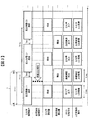
図1は、本実施の形態に係る自動分析装置の基本構成を示す図である。ここでは、自動分析装置の一態様として、ターンテーブル方式の生化学分析部と血液凝固時間分析ユニットとを備えた複合型の自動分析装置の例について説明する。
<About the basic configuration of the device>
FIG. 1 is a diagram showing a basic configuration of an automatic analyzer according to the present embodiment. Here, as an aspect of the automatic analyzer, an example of a combined automatic analyzer including a turntable biochemical analyzer and a blood coagulation time analysis unit will be described.
本図に示すように、自動分析装置1は、その筐体上に反応ディスク13、サンプルディスク11、第1試薬ディスク15、第2試薬ディスク16、血液凝固時間分析ユニット2、検出器(生化学分析用検出器)19が配置されている。
As shown in this figure, the
反応ディスク13は、時計回り、反時計回りに回転自在なディスク状のユニットであって、反応容器26をその円周上に複数個配置することができる。
The
サンプルディスク11は、時計回り、反時計回りに回転自在なディスク状のユニットであって、標準サンプルや被検サンプル等のサンプルを収容するサンプル容器27をその円周上に複数個配置することができる。
The sample disk 11 is a disk-shaped unit that can be rotated clockwise and counterclockwise, and a plurality of
第1試薬ディスク15、第2試薬ディスク16は、時計回り、反時計回りに回転自在なディスク状のユニットであって、サンプルに含まれる各検査項目の成分と反応する成分を含有する試薬を収容する試薬容器をその円周上に複数後配置できる。また、本図には示していないが、第1試薬ディスク15、第2試薬ディスク16では、保冷機構等を備えることにより、配置された試薬容器内の試薬を保冷可能に構成することもできる。
The first reagent disk 15 and the
サンプルディスク11と反応ディスク13の間にはサンプル分注プローブ12が配置されており、サンプル分注プローブ12の回転動作によってサンプルディスク11上のサンプル容器27、反応ディスク13上の反応容器26、及び血液凝固時間分析ユニット2のサンプル分注ポジション18における反応容器28においてサンプルの吸引および分注動作が可能なように配置されている。
A
同様に、第1試薬ディスク16と反応ディスク13の間には第1試薬分注プローブ17(生化学分析用、第1の試薬分注機構)が、第2試薬ディスク15と反応ディスク13の間には第2試薬分注プローブ14(生化学用)が配置されており、それぞれ回転動作により反応ディスク13上の反応容器26と第1試薬ディスク15、第2試薬ディスク16上の試薬容器内の吸引、吐出といった分注動作が可能なように配置されている。
Similarly, a first reagent dispensing probe 17 (for biochemical analysis, first reagent dispensing mechanism) is disposed between the
血液凝固時間分析ユニット2は、主として、血液凝固時間検出部21、血液凝固試薬分注プローブ20(第2の試薬分注機構)、使い捨て反応容器マガジン25、サンプル分注ポジション19、反応容器移送機構23、反応容器廃棄口24、光学ジグマガジン22から構成される。
The blood coagulation
次に、自動分析装置1に係る制御系、及び信号処理系について説明する。制御系として全体制御部102と測定制御部103を有しており、全体制御部102はインターフェース101を介して、サンプル分注制御部201、試薬分注制御部(1)205、試薬分注制御部(2)206、血液凝固試薬分注制御部203、移送機構制御部202に接続されており、各制御部に対して指令となる信号を送信する。測定制御部103は、サンプルと試薬との混合反応の程度に応じて時間変化する光強度の測定値を演算処理し、予め取得したキャリブレーション値をもとに、分析対象物の濃度もしくは反応時間(血液凝固分野では凝固時間などを指す)を算出する。また、予め定めた判定閾値との比較結果に基づいて、試料に含まれる分析対象物の濃度や反応時間を判断し、良否の判定を実施することもできる。算出された濃度もしくは反応時間は、表示部106に出力されるとともに、記憶部104に記憶される。
Next, a control system and a signal processing system related to the
サンプル分注制御部201は、全体制御部102から受けた指令に基づいて、サンプル分注プローブ12によるサンプルの分注動作を制御する。
The sample
また、試薬分注制御部(1)205および試薬分注制御部(2)206は、全体制御部102から受けた指令に基づいて、第1試薬分注プローブ17、第2試薬分注プローブ14による、試薬の分注動作を制御する。
In addition, the reagent dispensing control unit (1) 205 and the reagent dispensing control unit (2) 206 are based on a command received from the
また、移送機構制御部202は、全体制御部102から受けた指令に基づいて、反応容器移送機構23による、反応容器マガジン25、サンプル分注ポジション18、血液凝固時間検出部21の反応ポート209、反応容器廃棄口24の間における血液凝固分析用の使い捨ての反応容器28の移送動作を制御する。
In addition, the transfer mechanism control unit 202 performs the
また、血液凝固試薬分注制御部203は、全体制御部102から受けた指令に基づいて、反応ポート209に移載された、サンプル分注プローブ12によって分注されたサンプルを収容する反応容器28に対して、血液凝固試薬分注プローブ20によって血液凝固用の試薬の分注を行う。あるいは、反応容器26内で混合されたサンプルと血液凝固分析用の第1試薬との混合液である前処理液を、血液凝固試薬分注プローブ20によって空の反応容器28に対して分注する。この場合、その後前処理液を収容する反応容器28に対して、血液凝固分析用の第2試薬の分注を行う。ここで、血液凝固分析用の試薬は第1試薬ディスク15、第2試薬ディスク16に配置されており、第1試薬分注プローブ17、第2試薬分注プローブ18によって、必要に応じて反応ディスク13上の反応容器26に一旦分注されたのち、血液凝固分析に用いられる。
In addition, the blood coagulation reagent dispensing
なお、本図において全体制御部102と測定制御部103と独立した構成として説明したが、単一の制御部として自動分析装置の全体を制御するように構成することもできる。
Although the
使い捨ての反応容器(血液凝固分析用)28内の反応液の透過光または散乱光、反応容器(生化学分析用、第1の反応容器)26内の反応液の透過光または散乱光は、血液凝固時間分析用検出基板207および生化学項目用検出基板208によって光電変換、信号増幅され、アナログ電圧として共通A/D変換基板204へ送られる。その後共通A/D変換基板204よってデジタル信号に変換されたそれぞれの測光値は、記憶部104に取り込まれる。血液凝固時間分析用検出基板207、生化学項目用検出基板208、および共通A/D変換基板204の動作の詳細は図2を用いて後述する。
The transmitted light or scattered light of the reaction liquid in the disposable reaction container (for blood coagulation analysis) 28 and the transmitted light or scattered light of the reaction liquid in the reaction container (for biochemical analysis, first reaction container) 26 are blood. Photoelectric conversion and signal amplification are performed by the
<生化学項目の分析について>
この自動分析装置1による生化学項目の分析は、次の手順で行われる。まず、操作者は操作部105を用いて各サンプルに対し検査項目を依頼する。依頼された検査項目についてサンプルを分析するために、サンプル分注プローブ12は分析パラメータに従ってサンプル容器27から反応容器(生化学分析用)26へ所定量のサンプルを分注する。
<Analysis of biochemical items>
Analysis of biochemical items by the
サンプルが分注された反応容器(生化学分析用)26は、反応ディスク13の回転によって移送され、試薬受け入れ位置に停止する。第1試薬分注プローブ17、第2試薬分注プローブ14のピペットノズルは、該当する検査項目の分析パラメータにしたがって、反応容器(生化学分析用)26に所定量の試薬液を分注する。サンプルと試薬の分注順序は、この例とは逆に、サンプルより試薬が先であってもよい。
The reaction container (for biochemical analysis) 26 into which the sample has been dispensed is transferred by the rotation of the
その後、図示しない攪拌機構により、サンプルと試薬との攪拌が行われ、混合される。この反応容器(生化学分析用)26が、測光位置を横切る時、検出器(生化学分析用検出器)19により反応液の透過光または散乱光が測光される。測光された透過光または散乱光は、共通A/D変換基板204により光量に比例した数値のデータに変換され、インターフェース101を経由して、記憶部104に取り込まれる。
Thereafter, the sample and the reagent are stirred and mixed by a stirring mechanism (not shown). When the reaction vessel (for biochemical analysis) 26 crosses the photometric position, the detector (biochemical analysis detector) 19 measures the transmitted light or scattered light of the reaction solution. The measured transmitted light or scattered light is converted into numerical data proportional to the amount of light by the common A /
この変換された数値を用い、検査項目毎に指定された分析法により予め測定しておいた検量線に基づき、濃度データが算出される。各検査項目の分析結果としての成分濃度データは、表示部106に出力される。
Using the converted numerical value, concentration data is calculated based on a calibration curve measured in advance by an analysis method designated for each inspection item. Component concentration data as an analysis result of each inspection item is output to the
以上の測定動作が実行される前に、操作者は、分析に必要な種々のパラメータの設定や試薬およびサンプルの登録を、表示部106の操作画面および操作部105を介して行う。また、操作者は、測定後の分析結果を表示部106上の操作画面により確認する。
Before the measurement operation described above is executed, the operator sets various parameters necessary for analysis and registers reagents and samples via the operation screen of the
<血液凝固時間項目の分析について>
また、自動分析装置1による血液凝固時間項目の分析は、主に次の手順で行われる。
<Analysis of blood coagulation time items>
The analysis of blood coagulation time items by the
まず、操作者はキーボード等の操作部105を用いて各サンプルに対し検査項目を依頼する。依頼された検査項目についてサンプルを分析するために、反応容器移送機構23は使い捨て(ディスポーザブル)の反応容器(血液凝固分析用、第2の反応容器)28を反応容器マガジン25からサンプル分注ポジション18へ移送する。サンプル分注プローブ12は分析パラメータに従ってサンプル容器27から反応容器(血液凝固分析用)28へ所定量のサンプルを分注する。
First, the operator requests inspection items for each sample using the
サンプルが分注された反応容器(血液凝固分析用)28は、反応容器移送機構23によって血液凝固時間検出部21の反応ポート209へ移送され、所定の温度へ昇温される。第1試薬分注プローブ17は、該当する検査項目の分析パラメータにしたがって、反応ディスク13上の反応容器(生化学分析用)26に所定量の試薬液を分注する。反応ディスク13には、図示しない恒温槽が設けられているため、反応容器(生化学分析)26に分注された試薬液は37℃に温められる。
The reaction container (for blood coagulation analysis) 28 into which the sample has been dispensed is transferred to the
その後、血液凝固分注機構20は反応セル(生化学分析用)26に分注されている試薬を吸引し、血液凝固試薬分注プローブ20内で、図示しない昇温機構により所定の温度に昇温した後、反応容器(血液凝固分析用)28に吐出する。
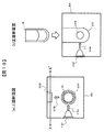
試薬が吐出された時点から、反応容器(血液凝固分析用)28に照射された光の透過光または散乱光の測光が開始される。図10は、本実施の形態に係る血液凝固検出部における反応ポートの基本構成を示す図である。(a)は上面断面図、(b)は(a)に示すX−X’面を正面とした場合の断面図である。本図に示されるように、反応ポート209には、反応容器(血液凝固分析用)28が設置される反応容器設置部2101、反応容器設置部2101に設置された反応容器(血液凝固分析用)28に光を照射する光源2102、照射された光2104の散乱光2105を検出する検出器2103(血液凝固分析用検出器、第2の検出器)が備えられる。なお、図1に示した構成では、血液凝固時間検出部21は、複数の反応ポート201を備えているが、単一の反応ポート209を備えるように構成することもできる。また、本図においては検出器2103(血液凝固分析用検出器、第2の検出器)が散乱光を検出する態様について説明したが、図1にて上述した通り、透過光を検出する態様にも適用可能である。
Thereafter, the blood coagulation /
From the time when the reagent is discharged, photometry of transmitted light or scattered light irradiated on the reaction container (for blood coagulation analysis) 28 is started. FIG. 10 is a diagram showing a basic configuration of the reaction port in the blood coagulation detector according to the present embodiment. (A) is upper surface sectional drawing, (b) is sectional drawing when the XX 'surface shown to (a) is made into the front. As shown in this figure, the
図1に戻り、測光された透過光または散乱光は、共通A/D変換基板204により光量に比例した数値のデータに変換され、インターフェース101を経由して、記憶部104に取り込まれる。
Returning to FIG. 1, the measured transmitted light or scattered light is converted into numerical data proportional to the amount of light by the common A /
この変換された数値を用い、血液凝固反応に要した時間(以下、単に血液凝固時間ということがある)を求める。例えば、APTT(活性化部分トロンボプラスチン時間)等の検査項目については、このようにして求めた血液凝固時間を分析結果として出力する。ここで、Fbg(フィブリノーゲン)等の検査項目については、求めた血液凝固時間に対して、さらに、検査項目毎に指定された分析法により予め測定しておいた検量線に基づき、成分濃度のデータを求めて分析結果として出力する。各検査項目の分析結果としての血液凝固時間や成分濃度のデータは、表示部106の画面に出力される。
Using this converted numerical value, the time required for the blood coagulation reaction (hereinafter sometimes simply referred to as blood coagulation time) is obtained. For example, for test items such as APTT (activated partial thromboplastin time), the blood coagulation time thus determined is output as an analysis result. Here, for test items such as Fbg (fibrinogen), data on component concentrations are obtained based on a calibration curve previously measured by the analysis method specified for each test item for the obtained blood coagulation time. Is output as an analysis result. Blood clotting time and component concentration data as analysis results of each test item are output on the screen of the
ここで、上記の測定動作が実行される前に、操作者は、分析に必要な種々のパラメータの設定や試薬、サンプルの登録を、表示部106の操作画面および操作部105を介して予め行う。また、操作者は、測定後の分析結果を表示部106上の操作画面により確認することができる。
Here, before the above measurement operation is performed, the operator performs various parameter settings necessary for analysis and registration of reagents and samples in advance via the operation screen of the
また、サンプル分注プローブ12によって吐出されるサンプルの吐出先は反応容器(生化学分析用)26であってもよい。この場合、上述したように予め反応容器(生化学分析用)26内で前処理液と反応させたのちに、血液凝固分注プローブ23によって、反応容器(血液凝固分析用)28に分注することもできる。
Further, the discharge destination of the sample discharged by the
血液凝固分注プローブ20では、先に反応容器(血液凝固分析用)28に収容されているサンプルに対して、試薬が吐出されたときの勢いによって、反応容器(血液凝固分析用)28内におけるサンプルとの混合を行う、吐出攪拌と呼ばれる撹拌を行う。サンプルと試薬の分注順序は、この例とは逆に、サンプルより試薬の方が先であってもよく、この場合はサンプルが吐出されたときの勢いによって、試薬との混合を行うことができる。
In the blood coagulation / dispensing
ここで、吐出攪拌では確実な攪拌を実行するために血液凝固試薬分注プローブ20の先端の位置の反応容器に対する位置精度を高く保つことが重要であり、その位置調整には特に注意を要する。
Here, in the discharge agitation, it is important to maintain high positional accuracy with respect to the reaction container at the position of the tip of the blood coagulation
<測定データの処理手順について>
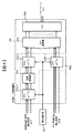
図2は、本実施の形態に係る自動分析装置における基板の基本構成を示す図である。
<Measurement data processing procedure>
FIG. 2 is a diagram showing a basic configuration of the substrate in the automatic analyzer according to the present embodiment.
本図に示すように、自動分析装置1には、測定データを処理するための構成として、血液凝固時間分析ユニット用の血液凝固時間分析用検出基板207と、生化学分析部用の生化学項目用検出基板208、及び、測定データのA/D変換を行う共通A/D変換基板204を備えている。
As shown in this figure, the
血液凝固時間分析用検出基板207には、サンプルからの散乱光を電流値へ変換する光電変換素子207aと、その信号を電圧値へ変換および増幅する増幅回路207bが備わっている。
The blood coagulation time
生化学項目用検出基板208には、サンプルからの透過光を電流値へ変換する光電変換素子208aと、その信号を電圧値へ変換および増幅する増幅回路208bが備わっている。
The biochemical
共通A/D変換基板204は、血液凝固時間分析用検出基板207及び生化学項目用検出基板208から送られてくるアナログ電圧のデータを受け取り、受け取ったデータの中から後段のA/D変換部204bへ送り出す信号を選択する信号切換部204aと、信号切換部204aからの信号を受け取り、アナログ電圧からデジタル値のデータへ変換するA/D変換部204bと、そのデジタル値のデータを処理するCPU205cで構成されている。
The common A /
ここで、図8は生化学分析項目のデータ処理用の検出基板(単体)の基本構成を示し、
図9は血液凝固時間分析のデータ処理用の検出基板(単体)の基本構成を示す。従来では、複合型の自動分析装置においても、これらの図に示すように、それぞれの分析項目について得られた測定データの処理を、独立した基板で実施していたため、処理の効率が低く、また測定データに機差が影響するおそれがあった。これに対し、本実施の形態では、図2にて示した共通A/D変換基板204を用いて、後述する分析動作、データ処理動作を実行する。
Here, FIG. 8 shows a basic configuration of a detection substrate (single unit) for data processing of biochemical analysis items,
FIG. 9 shows a basic configuration of a detection substrate (single unit) for data processing of blood coagulation time analysis. Conventionally, even in a complex type automatic analyzer, as shown in these figures, processing of measurement data obtained for each analysis item has been performed on an independent substrate, so that the processing efficiency is low, and There was a risk of machine differences affecting measurement data. In contrast, in the present embodiment, an analysis operation and a data processing operation described later are executed using the common A /
図3は、本実施の形態に係る生化学分析、血液凝固分析の分析動作及びデータ処理動作を示すタイミングチャートである。ここで、データ処理動作は、図2に示した構成における共通A/D変換基板204にて行われる。
FIG. 3 is a timing chart showing the analysis operation and data processing operation of biochemical analysis and blood coagulation analysis according to the present embodiment. Here, the data processing operation is performed by the common A /
図3に示すように、全体制御部102は、反応容器(生化学分析用)26が検出器(生化学分析用検出器)19の前を通過する期間を含む期間t1(ある反応容器(生化学分析用)26[図中反応容器(1)]が検出器(生化学分析用検出器)19の前を通過開始する時点[図中A点]から、隣接するポジションに位置する他の反応容器(生化学分析用)26[図中反応容器(2)]が通過開始する時点[図中B点]までの間隔)内に、血液凝固試薬分注プローブ20からの試薬吐出を行うようにその動作を制御している。
As shown in FIG. 3, the
共通A/D変換基板204上の信号切換部204aでは、測定制御部103から指示される切換信号に基づいて、検出器(生化学分析用検出器)19、検出器(血液凝固分析用検出器)2103からそれぞれ血液凝固時間分析用検出基板207、生化学項目用検出基板208を介して送られてくるアナログ電圧のうち、特定のデータをA/D変換部204bに選択的に送信するように切換を行っている。すなわち、本図に示すように、生化学分析については、反応容器(生化学分析用)26が検出器(生化学分析用検出器)19の前を通過したことをトリガとして生化学分析に関するデータのA/D変換を行い、血液凝固分析については、試薬吐出の動作をトリガとして血液凝固分析に関するデータの最初のA/D変換を行うように信号を切り換えている。この動作については図7を用いて以下に詳述する。ここで、血液凝固分析については、複数の反応ポート209のうちの特定の1つの反応ポート209に着目した場合について本図に示している。すなわち、血液凝固分析では、検出器(血液凝固分析用検出器)2103では1つの反応ポート209に保持された反応容器(血液凝固分析用)28に収容される反応液について、血液凝固反応が完了するまで複数回のデータの検出、出力及びA/D変換を行っている。また、試薬吐出動作に関しては、その開始のタイミングのみを示し、吐出時間の長さは本図において表示を省略している。
In the
図7は、本実施の形態に係る自動分析装置における生化学分析、血液凝固分析の分析動作及びデータ処理動作を説明するフローチャートである。まず、分析が開始すると(a)、生化学分析については、反応ディスク13が回転し(b−1)、検知センサ30は反応容器(生化学分析用)26が検出器(生化学分析用検出器)19の前を通過し始めたたことを検知する(c−1)。測定制御部103は、検知センサ30による反応容器(生化学分析用)26の検知を受けて(d−1)、生化学項目用検出基板208からのアナログ電圧のうち、A/D変換部204bへ通過させるデータを指示する切換信号を信号切換部204aへ送信する(e−1)。信号切換部204aは、切換信号に基づいて、特定のアナログ電圧のデータを、A/D変換部204bに送信する(f−1)。その後、A/D変換部204bでは送信されたアナログ電圧をデジタル値のデータに変換するA/D変換処理を行う(g−1)。ここで、図6は、本実施の形態に係る自動分析装置における反応容器と検知センサとの構成を示す。反応容器(生化学分析用)26の検知は、本図に示すように、反応ディスク13の下部に設けられた位置指示器29が検知センサ30を通り過ぎることで実施される。このように、反応容器(生化学分析用)26が配置される位置に合わせて位置指示器29を設置することで、検知することができる。
FIG. 7 is a flowchart for explaining the analysis operation and data processing operation of biochemical analysis and blood coagulation analysis in the automatic analyzer according to the present embodiment. First, when the analysis is started (a), for the biochemical analysis, the
また、血液凝固分析については、測定が開始すると(a)、上述したタイミングにおいて、血液凝固試薬分注プローブ20から反応容器(血液凝固分析用)28へ試薬を吐出する(b−2)。試薬の吐出動作が実行されたことを、全体制御部102からの試薬吐出指令信号を受信することによって検知すると(c−2)、測定制御部103は、血液凝固時間分析用検出基板207からのアナログ電圧のうち、A/D変換部204bへ通過させるデータを指示する切換信号を信号切換部204aへ送信する(d−2)。信号切換部204aは、切換信号に基づいて、特定のアナログ電圧のデータを、A/D変換部204bに送信する(e−2)。その後、A/D変換部204bでは送信されたアナログ電圧をデジタル値のデータに変換するA/D変換処理を行う(f−2)。
As for blood coagulation analysis, when measurement is started (a), the reagent is discharged from the blood coagulation
このように、生化学分析、血液凝固分析において上述したフローをそれぞれ実行することにより、単一の装置において、異なる種別の分析について、測定データの基板を共通化させつつ、かつ、それぞれの分析におけるA/D変換のタイミングを重ならないように制御することができる。 As described above, by executing the above-described flows in the biochemical analysis and the blood coagulation analysis, in a single apparatus, the measurement data can be shared for different types of analysis, and each analysis can be performed. A / D conversion timing can be controlled so as not to overlap.
なお、図2に示した構成では、異なる種別の分析として、生化学分析項目と血液凝固時間分析のA/D変換の動作タイミングが重ならないよう工夫することで、1枚の共通A/D変換基板204でのA/D変換を実現可能とする態様を一例として説明しているが、これに限られるものではなく、当然のことながらその他の分析との組合せについても適用可能である。例えば、免疫分析や電解質分析についても上述した手法により同様に1枚の共通A/D変換基板で処理を実施することが可能である。
In the configuration shown in FIG. 2, as a different type of analysis, one common A / D conversion is performed by devising that the biochemical analysis items and the A / D conversion operation timing of the blood coagulation time analysis do not overlap. Although an example in which the A / D conversion on the
上述した実施の形態では、図3に示したように、A/D変換開始のトリガとなる動作のタイミングを調整することで、生化学分析および血液凝固分析のA/D変換の動作が重ならないように制御する手法について述べた。本実施の形態では、測定データを一時的に保存することにより、双方の分析における測定データのA/D変換の動作が重ならないように制御する手法について説明する。 In the above-described embodiment, as shown in FIG. 3, the A / D conversion operations of biochemical analysis and blood coagulation analysis do not overlap by adjusting the timing of the operation that triggers the start of A / D conversion. The control method was described as above. In the present embodiment, a method for controlling the measurement data so as not to overlap each other by temporarily storing the measurement data in both analyzes will be described.
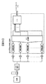
図4は、本実施の形態に係る自動分析装置における信号蓄積部を備えた基板の基本構成を示す図である。 FIG. 4 is a diagram showing a basic configuration of a substrate provided with a signal storage unit in the automatic analyzer according to the present embodiment.
本図に示す構成では、図2に示した構成の信号切換部204aが、測定データを一時的に保存する信号蓄積部204eと、A/D変換部204bへ送信するアナログ電圧のデータの切換および信号蓄積部204eの動作切換を、測定制御部103からの指示に基づいて実行する接点切換部204d−1〜d−3(SW1、SW2、SW3)から構成されている点で異なる。
In the configuration shown in this figure, the
本構成では、血液凝固時間分析用検出基板207からの信号を蓄積することができる。
In this configuration, signals from the blood clotting time
図5は、本実施の形態に係る信号切換動作、及び生化学分析、血液凝固分析のデータ処理動作を説明する図である。 FIG. 5 is a diagram for explaining the signal switching operation and the data processing operation of biochemical analysis and blood coagulation analysis according to the present embodiment.
本図に示すように、生化学分析項目のA/D変換時はSW1およびSW3をONし、SW2をOFFすることで、血液凝固時間分析項目の測定データを信号蓄積部204eに蓄積しつつ、この間に生化学分析項目の測定データをA/D変換部204bへ送信しA/D変換を行う。
As shown in this figure, at the time of A / D conversion of biochemical analysis items, SW1 and SW3 are turned on and SW2 is turned off, thereby accumulating measurement data of blood coagulation time analysis items in the
生化学分析項目のA/D変換完了後、SW1およびSW3をOFFし、SW2をONすることで、生化学分析項目の測定データがA/D変換部204bへ送信せずに、上述した工程にて蓄積した血液凝固時間分析項目の測定データをA/D変換部204bへ送信し、A/D変換を行う。
After the A / D conversion of the biochemical analysis item is completed, the SW1 and SW3 are turned off and the SW2 is turned on, so that the measurement data of the biochemical analysis item is not transmitted to the A /
血液凝固時間分析のA/D変換が完了した後は、再びSW1およびSW3をONし、SW2をOFFすることで生化学分析項目のA/D変換を行う。 After the A / D conversion of the blood coagulation time analysis is completed, SW1 and SW3 are turned on again, and SW2 is turned off to perform A / D conversion of the biochemical analysis items.
このように、測定制御部103の指示に基づいて、「SW1およびSW3をONとし、SW2をOFF」とすることにより信号蓄積部204eに信号を蓄積する状態と、「SW1およびSW3をOFFとし、SW2をON」とすることにより蓄積された信号を信号蓄積部204eから送信する状態との間の信号蓄積部204eの動作を切換えることができる。
As described above, based on the instruction of the
以後、この動作を繰り返し実行することで、生化学分析項目と血液凝固時間分析項目のA/D変換処理を交互に行うこととなる。 Thereafter, by repeatedly executing this operation, A / D conversion processing of biochemical analysis items and blood clotting time analysis items is performed alternately.
本実施の形態によれば、信号蓄積部204eに信号を蓄積し、適切なタイミングで送信するように動作を切り換えることができるので、実施例1においてA/D変換開始のトリガとしていた各機構の動作のタイミングが制限されず、より分析動作に自由度を持たせることができる。特に、上述した生化学分析、血液凝固分析に加えて、例えばさらにイオン選択電極(ISE)分析等の分析を共通の基板を用いて実行する場合には、実施例1の態様においてはより各分析機構の動作のタイミングを厳密にコントロールする必要が生じるが、本態様によればこのような制限を低減することが可能となる。 なお、図4に示した構成では、A/D変換の動作が重なった場合に、血液凝固時間分析用検出基板207からの信号を信号蓄積部204eに蓄積することでA/D変換の動作の重なりを解消しているが、信号蓄積部204eと接点切換部204dの配置を変更して、生化学項目用検出基板208からの信号を蓄積してA/D変換の動作の重なりを解消する構成も同様に実現可能である。但し、血液凝固分析では、その反応時間の終了時点が固定ではなく、試料によって異なる場合があるため、生化学分析と比較して新たな分析を開始できるタイミングを予測しづらいという事情がある。そのため、信号蓄積部204eを血液凝固時間分析用検出基板207と接続して信号を蓄積しておくことで、より効率良くデータの処理を実行できる場合がある。
According to the present embodiment, since the signal can be stored in the
また、図4に示した構成では、異なる種別の分析として、生化学分析項目と血液凝固時間分析項目のA/D変換の動作タイミングが重ならないよう工夫することで、1枚の共通A/D変換基板204でのA/D変換を実現可能とする態様を一例として説明しているが、これに限られるものではなく、当然のことながらその他の分析との組合せについても適用可能である。例えば免疫分析や電解質分析についても同様に1枚のA/D変換基板で対応が可能である。
In the configuration shown in FIG. 4, as a different type of analysis, one common A / D is created by devising that the operation timing of A / D conversion of the biochemical analysis item and the blood coagulation time analysis item does not overlap. Although an example in which the A / D conversion on the
なお、本発明は上記した実施の形態に限定されるものではなく、様々な変形例が含まれる。例えば、上記した実施の形態は本発明を分かりやすく説明するために詳細に説明したものであり、必ずしも説明した全ての構成を備えるものに限定されるものではない。また、ある実施の形態の構成の一部を他の実施の形態の構成に置き換えることが可能であり、また、ある実施の形態の構成に他の実施の形態の構成を加えることも可能である。また、各実施の形態構成の一部について、他の構成の追加・削除・置換をすることが可能である。 In addition, this invention is not limited to above-described embodiment, Various modifications are included. For example, the above-described embodiment has been described in detail for easy understanding of the present invention, and is not necessarily limited to one having all the configurations described. Further, a part of the configuration of one embodiment can be replaced with the configuration of another embodiment, and the configuration of another embodiment can be added to the configuration of one embodiment. . Moreover, it is possible to add / delete / replace other configurations for a part of the configuration of each embodiment.
1・・・自動分析装置
2・・・血液凝固時間分析ユニット
11・・・サンプルディスク
12・・・サンプル分注プローブ
13・・・反応ディスク
14・・・第2試薬分注プローブ
15・・・第1試薬ディスク
16・・・第2試薬ディスク
17・・・第1試薬分注プローブ(第1の試薬分注機構)
18・・・サンプル分注ポジション
19・・・検出器(生化学分析用検出器、第1の検出器)
20・・・血液凝固試薬分注プローブ(第2の試薬分注機構)
21・・・血液凝固時間検出部
22・・・光学ジグマガジン
23・・・反応容器移送機構
24・・・反応容器廃棄口
25・・・使い捨て反応容器マガジン
26・・・反応容器(生化学分析用、第1の反応容器)
27・・・サンプル容器
28・・・反応容器(血液凝固分析用、第2の反応容器)
29・・・位置指示器
30・・・検知センサ
101・・・インターフェース
102・・・全体制御部
103・・・測定制御部
104・・・記憶部
105・・・操作部
106・・・表示部
201・・・サンプル分注制御部
202・・・移送機構制御部
203・・・血液凝固試薬分注制御部
204・・・共通A/D変換基板
204a・・・信号切換部
204b・・・A/D変換部
204c・・・CPU
204d−1〜d−3・・・接点切換部
204e・・・信号蓄積部
205・・・試薬分注制御部(1)
206・・・試薬分注制御部(2)
207・・・血液凝固時間分析項目用検出基板
207a・・・光電変換素子
207b・・・増幅回路
208・・・生化学分析項目用検出基板
207a・・・光電変換素子
207b・・・増幅回路
209・・・反応ポート
2101・・・反応容器設置部
2102・・・光源
2103・・・検出器(血液凝固分析用検出器、第2の検出器)
2104・・・照射光
2105・・・散乱光
DESCRIPTION OF
18 ... Sample dispensing
20 ... Blood coagulation reagent dispensing probe (second reagent dispensing mechanism)
DESCRIPTION OF
27 ...
29 ...
204d-1 to d-3 ... contact switching
206 ... Reagent dispensing control unit (2)
207... Blood clotting time analysis
2104 ...
Claims (12)
試薬を第1の反応容器に分注する第1の試薬分注機構と、
試料と試薬とを混合し反応させるための第2の反応容器が配置される反応ポートと、
試薬を第2の反応容器に分注する第2の試薬分注機構と、
第1の反応容器及び第2の反応容器に試料を分注する試料分注機構と、
当該反応ディスクに配置された第1の反応容器に保持された試料と試薬との混合液に光を照射する第1の光源と、当該照射された光を検出する第1の検出器と、
当該反応ポートに配置された第2の反応容器に保持された試料と試薬との混合液に光を照射する第2の光源と、当該照射された光を検出する第2の検出器と、
当該検出結果に基づいて試料を分析する制御部と、を備え、
当該検出された光について、アナログデータからデジタルデータに変換するアナログ/デジタル変換部と、
前記第1の検出器によって検出された第1の信号及び前記第2の検出器によって検出された第2の信号を受け取り、当該受け取った信号のうち、特定の信号を選択的に前記アナログ/デジタル変換部に送る信号切換部を有し、
前記制御部は、
前記信号切換部の動作を制御し、当該アナログ/デジタル変換部における、前記第1の信号を変換するタイミングと、前記第2の信号を変換するタイミングとが互いに重複しないように、当該受け取った信号のうち、前記アナログ/デジタル変換部に送る信号を選択することを特徴とする自動分析装置。 A rotatable reaction disk in which a first reaction vessel for mixing and reacting a sample and a reagent is arranged circumferentially;
A first reagent dispensing mechanism for dispensing the reagent into the first reaction vessel;
A reaction port in which a second reaction vessel for mixing and reacting the sample and the reagent is disposed;
A second reagent dispensing mechanism for dispensing the reagent into the second reaction vessel;
A sample dispensing mechanism for dispensing a sample into the first reaction container and the second reaction container;
A first light source for irradiating light to a mixed liquid of a sample and a reagent held in a first reaction vessel disposed on the reaction disk, a first detector for detecting the irradiated light,
A second light source for irradiating light to the mixed liquid of the sample and the reagent held in the second reaction container disposed in the reaction port, a second detector for detecting the irradiated light,
A control unit for analyzing the sample based on the detection result,
An analog / digital converter that converts the detected light from analog data to digital data;
The first signal detected by the first detector and the second signal detected by the second detector are received, and a specific signal is selectively selected from the received signals. It has a signal switching part to send to the conversion part,
The controller is
The received signal is controlled so that the timing of converting the first signal and the timing of converting the second signal in the analog / digital conversion unit do not overlap each other by controlling the operation of the signal switching unit. Among them, a signal to be sent to the analog / digital converter is selected.
前記制御部は、
前記反応ディスクに配置された第1の反応容器が、前記第1の検出器の前を通過し始めた後に、前記第1の信号を前記アナログ/デジタル変換部に送るように前記信号切換部の動作を制御することを特徴とする自動分析装置。 An automatic analyzer according to claim 1, wherein
The controller is
After the first reaction vessel arranged on the reaction disk starts to pass in front of the first detector, the signal switching unit is configured to send the first signal to the analog / digital conversion unit. An automatic analyzer characterized by controlling its operation.
前記制御部は、
前記第2の試薬分注機構が、試薬を前記第2の反応容器に分注した後に、前記第2の信号を前記アナログ/デジタル変換部に送るように前記信号切換部の動作を制御することを特徴とする自動分析装置。 An automatic analyzer according to claim 1 or 2,
The controller is
The second reagent dispensing mechanism controls the operation of the signal switching unit so as to send the second signal to the analog / digital conversion unit after dispensing a reagent into the second reaction vessel. Automatic analyzer characterized by
前記信号切換部と、前記アナログ/デジタル変換部とは、前記第1の検出器及び前記第2の検出器について共通した基板上に搭載されていることを特徴とする自動分析装置。 The automatic analyzer according to any one of claims 1 to 3,
The automatic analyzer according to claim 1, wherein the signal switching unit and the analog / digital conversion unit are mounted on a common substrate for the first detector and the second detector.
前記信号切換部は、
前記第1の検出器または前記第2の検出器の一方の検出器と接続され、当該接続された検出器によって検出された第1の信号または第2の信号を受け取り、当該受け取った信号を一時的に記憶する信号蓄積部を有することを特徴とする自動分析装置。 The automatic analyzer according to any one of claims 1 to 4,
The signal switching unit is
The first detector or the second detector is connected to one detector, receives the first signal or the second signal detected by the connected detector, and temporarily receives the received signal. An automatic analyzer characterized by having a signal accumulating unit for storing it automatically.
当該信号蓄積部に接続された第1の検出器または第2の検出器の一方の検出器と、前記信号蓄積部との間に配置され、前記信号蓄積部よりも先に、当該接続された検出器によって検出された第1の信号または第2の信号を受け取り、当該受け取った信号のうち特定の信号を選択的に前記信号蓄積部に送るように切換を行う第1の接点切換部を備えることを特徴とする自動分析装置。 An automatic analyzer according to claim 5, wherein
The first detector or the second detector connected to the signal storage unit is arranged between the detector and the signal storage unit, and the connection is made before the signal storage unit. A first contact switching unit that receives the first signal or the second signal detected by the detector and performs switching so that a specific signal among the received signals is selectively sent to the signal storage unit; An automatic analyzer characterized by that.
前記信号蓄積部と、前記アナログ/デジタ
前記第1の検出器または前記第2の検出器のうち、前記信号蓄積部に接続されていない他方の検出器と、前記アナログ/デジタル変換部との間に配置され、前記他方の検出器にル変換部との間に配置され、前記信号蓄積部に記憶された信号のうち、特定の信号を選択的に前記アナログ/デジタル変換部に送るように切換を行う第2の接点切換部を有することを特徴とする自動分析装置。 An automatic analyzer according to claim 6, wherein
Between the analog / digital conversion unit and the other detector not connected to the signal storage unit among the first detector or the second detector, and the analog / digital converter. The other detector is arranged between the signal conversion unit and the other detector, and the signal stored in the signal storage unit is switched to selectively send the signal to the analog / digital conversion unit. An automatic analyzer having a second contact switching unit for performing the above.
よって検出された第1の信号または第2の信号を受け取り、当該受け取った信号のうち特定の信号を選択的に前記アナログ/デジタル変換部に送るように切換を行う第3の接点切換部を有することを特徴とする自動分析装置。 An automatic analyzer according to claim 7,
Therefore, a third contact switching unit that receives the detected first signal or the second signal and performs switching so as to selectively send a specific signal among the received signals to the analog / digital conversion unit is provided. An automatic analyzer characterized by that.
前記制御部は、
前記第1の接点切換部及び前記第3の接点切換部がオン状態である期間は、前記第2の接点切換部をオフ状態とし、
前記第2の接点切換部がオン状態である期間は、前記第1の接点切換部及び前記第3の接点切換部をオフ状態とするように前記第1〜第3の接点切換部の動作を制御することを特徴とする自動分析装置。 An automatic analyzer according to claim 8, comprising:
The controller is
During the period in which the first contact switching unit and the third contact switching unit are on, the second contact switching unit is turned off,
During the period in which the second contact switching unit is in the on state, the first to third contact switching units are operated so as to turn off the first contact switching unit and the third contact switching unit. An automatic analyzer characterized by controlling.
前記第1の検出器は、当該第1の光源から照射された光の透過光または散乱光を検出し、
前記第2の検出器は、当該第2の光源から照射された光の散乱光を検出することを特徴とする自動分析装置。 An automatic analyzer according to any one of claims 1 to 9,
The first detector detects transmitted light or scattered light of light emitted from the first light source,
The automatic detector is characterized in that the second detector detects scattered light of light emitted from the second light source.
前記第2の反応容器は、ディスポーザブルであることを特徴とする自動分析装置。 An automatic analyzer according to claim 10, wherein
2. The automatic analyzer according to claim 2, wherein the second reaction vessel is disposable.
試薬を第1の反応容器に分注する第1の試薬分注機構と、
試料と試薬とを混合し反応させるための第2の反応容器が配置される反応ポートと、
試薬を第2の反応容器に分注する第2の試薬分注機構と、
第1の反応容器及び第2の反応容器に試料を分注する試料分注機構と、
当該反応ディスクに配置された第1の反応容器に保持された試料と試薬との混合液に光を照射する第1の光源と、当該照射された光を検出する第1の検出器と、
当該反応ポートに配置された第2の反応容器に保持された試料と試薬との混合液に光を照射する第2の光源と、当該照射された光を検出する第2の検出器と、
当該検出結果に基づいて試料を分析する制御部と、を備えた自動分析装置を用いた分析方法であって、
当該検出された光について、アナログデータからデジタルデータに変換するアナログ/デジタル変換部と、
前記第1の検出器によって検出された第1の信号及び前記第2の検出器によって検出された第2の信号を受け取り、当該受け取った信号のうち、特定の信号を選択的に前記アナログ/デジタル変換部に送る信号切換部を有し、
前記制御部は、
前記信号切換部の動作を制御し、当該アナログ/デジタル変換部における、前記第1の信号を変換するタイミングと、前記第2の信号を変換するタイミングとが互いに重複しないように、当該受け取った信号のうち、前記アナログ/デジタル変換部に送る信号を選択することを特徴とする分析方法。 A rotatable reaction disk in which a first reaction vessel for mixing and reacting a sample and a reagent is arranged circumferentially;
A first reagent dispensing mechanism for dispensing the reagent into the first reaction vessel;
A reaction port in which a second reaction vessel for mixing and reacting the sample and the reagent is disposed;
A second reagent dispensing mechanism for dispensing the reagent into the second reaction vessel;
A sample dispensing mechanism for dispensing a sample into the first reaction container and the second reaction container;
A first light source for irradiating light to a mixed liquid of a sample and a reagent held in a first reaction vessel disposed on the reaction disk, a first detector for detecting the irradiated light,
A second light source for irradiating light to the mixed liquid of the sample and the reagent held in the second reaction container disposed in the reaction port, a second detector for detecting the irradiated light,
A control unit for analyzing a sample based on the detection result, and an analysis method using an automatic analyzer comprising:
An analog / digital converter that converts the detected light from analog data to digital data;
The first signal detected by the first detector and the second signal detected by the second detector are received, and a specific signal is selectively selected from the received signals. It has a signal switching part to send to the conversion part,
The controller is
The received signal is controlled so that the timing of converting the first signal and the timing of converting the second signal in the analog / digital conversion unit do not overlap each other by controlling the operation of the signal switching unit. An analysis method, wherein a signal to be sent to the analog / digital conversion unit is selected.
Priority Applications (1)
| Application Number | Priority Date | Filing Date | Title |
|---|---|---|---|
| JP2016147963A JP6737529B2 (en) | 2016-07-28 | 2016-07-28 | Automatic analyzer |
Applications Claiming Priority (1)
| Application Number | Priority Date | Filing Date | Title |
|---|---|---|---|
| JP2016147963A JP6737529B2 (en) | 2016-07-28 | 2016-07-28 | Automatic analyzer |
Publications (2)
| Publication Number | Publication Date |
|---|---|
| JP2018017603A true JP2018017603A (en) | 2018-02-01 |
| JP6737529B2 JP6737529B2 (en) | 2020-08-12 |
Family
ID=61075185
Family Applications (1)
| Application Number | Title | Priority Date | Filing Date |
|---|---|---|---|
| JP2016147963A Active JP6737529B2 (en) | 2016-07-28 | 2016-07-28 | Automatic analyzer |
Country Status (1)
| Country | Link |
|---|---|
| JP (1) | JP6737529B2 (en) |
Cited By (2)
| Publication number | Priority date | Publication date | Assignee | Title |
|---|---|---|---|---|
| WO2019176297A1 (en) * | 2018-03-15 | 2019-09-19 | 株式会社日立ハイテクノロジーズ | Biochemistry/coagulation composite-type analysis device |
| JP7470362B2 (en) | 2020-01-29 | 2024-04-18 | 株式会社テクノメデイカ | Urine collection cup management device |
Citations (4)
| Publication number | Priority date | Publication date | Assignee | Title |
|---|---|---|---|---|
| JPS6222066A (en) * | 1985-07-23 | 1987-01-30 | Wako Pure Chem Ind Ltd | Latex agglutination reaction measuring instrument |
| JPH03135768A (en) * | 1989-07-24 | 1991-06-10 | Tritech Partners | Analyzing method and automatic analyzer |
| WO2013187210A1 (en) * | 2012-06-11 | 2013-12-19 | 株式会社 日立ハイテクノロジーズ | Automatic analysis apparatus |
| WO2016017289A1 (en) * | 2014-07-29 | 2016-02-04 | 株式会社 日立ハイテクノロジーズ | Automatic analysis apparatus |
-
2016
- 2016-07-28 JP JP2016147963A patent/JP6737529B2/en active Active
Patent Citations (4)
| Publication number | Priority date | Publication date | Assignee | Title |
|---|---|---|---|---|
| JPS6222066A (en) * | 1985-07-23 | 1987-01-30 | Wako Pure Chem Ind Ltd | Latex agglutination reaction measuring instrument |
| JPH03135768A (en) * | 1989-07-24 | 1991-06-10 | Tritech Partners | Analyzing method and automatic analyzer |
| WO2013187210A1 (en) * | 2012-06-11 | 2013-12-19 | 株式会社 日立ハイテクノロジーズ | Automatic analysis apparatus |
| WO2016017289A1 (en) * | 2014-07-29 | 2016-02-04 | 株式会社 日立ハイテクノロジーズ | Automatic analysis apparatus |
Cited By (2)
| Publication number | Priority date | Publication date | Assignee | Title |
|---|---|---|---|---|
| WO2019176297A1 (en) * | 2018-03-15 | 2019-09-19 | 株式会社日立ハイテクノロジーズ | Biochemistry/coagulation composite-type analysis device |
| JP7470362B2 (en) | 2020-01-29 | 2024-04-18 | 株式会社テクノメデイカ | Urine collection cup management device |
Also Published As
| Publication number | Publication date |
|---|---|
| JP6737529B2 (en) | 2020-08-12 |
Similar Documents
| Publication | Publication Date | Title |
|---|---|---|
| JP7450656B2 (en) | automatic analyzer | |
| US7842509B2 (en) | Blood analyzer and blood analyzing method | |
| JP6636047B2 (en) | Automatic analyzer and control method thereof | |
| JP2007198739A (en) | Autoanalyzer | |
| CN110023765B (en) | Automatic analyzer | |
| JP6550152B2 (en) | Automatic analyzer | |
| JP6737529B2 (en) | Automatic analyzer | |
| JP5946776B2 (en) | Automatic analyzer | |
| JP6766155B2 (en) | Automatic analyzer | |
| JP2007322394A (en) | Dispensing device and automated analyzer | |
| JP7395392B2 (en) | Automatic analyzer and analysis method | |
| WO2019176296A1 (en) | Automatic analysis device | |
| US11579159B2 (en) | Automatic analysis device | |
| JP2533527B2 (en) | Automatic analyzer | |
| JP2008298755A (en) | Medical photometer | |
| JP2009243995A (en) | Automatic analyzer |
Legal Events
| Date | Code | Title | Description |
|---|---|---|---|
| A521 | Request for written amendment filed |
Free format text: JAPANESE INTERMEDIATE CODE: A523 Effective date: 20160729 |
|
| RD04 | Notification of resignation of power of attorney |
Free format text: JAPANESE INTERMEDIATE CODE: A7424 Effective date: 20170120 |
|
| RD04 | Notification of resignation of power of attorney |
Free format text: JAPANESE INTERMEDIATE CODE: A7424 Effective date: 20170126 |
|
| RD02 | Notification of acceptance of power of attorney |
Free format text: JAPANESE INTERMEDIATE CODE: A7422 Effective date: 20170803 |
|
| RD04 | Notification of resignation of power of attorney |
Free format text: JAPANESE INTERMEDIATE CODE: A7424 Effective date: 20170804 |
|
| A621 | Written request for application examination |
Free format text: JAPANESE INTERMEDIATE CODE: A621 Effective date: 20190410 |
|
| A977 | Report on retrieval |
Free format text: JAPANESE INTERMEDIATE CODE: A971007 Effective date: 20200310 |
|
| A131 | Notification of reasons for refusal |
Free format text: JAPANESE INTERMEDIATE CODE: A131 Effective date: 20200317 |
|
| A521 | Request for written amendment filed |
Free format text: JAPANESE INTERMEDIATE CODE: A523 Effective date: 20200414 |
|
| TRDD | Decision of grant or rejection written | ||
| A01 | Written decision to grant a patent or to grant a registration (utility model) |
Free format text: JAPANESE INTERMEDIATE CODE: A01 Effective date: 20200616 |
|
| A61 | First payment of annual fees (during grant procedure) |
Free format text: JAPANESE INTERMEDIATE CODE: A61 Effective date: 20200714 |
|
| R150 | Certificate of patent or registration of utility model |
Ref document number: 6737529 Country of ref document: JP Free format text: JAPANESE INTERMEDIATE CODE: R150 |