JP2018017444A - Thermal storage device and installation structure of thermal storage device - Google Patents
Thermal storage device and installation structure of thermal storage device Download PDFInfo
- Publication number
- JP2018017444A JP2018017444A JP2016147272A JP2016147272A JP2018017444A JP 2018017444 A JP2018017444 A JP 2018017444A JP 2016147272 A JP2016147272 A JP 2016147272A JP 2016147272 A JP2016147272 A JP 2016147272A JP 2018017444 A JP2018017444 A JP 2018017444A
- Authority
- JP
- Japan
- Prior art keywords
- heat storage
- heat
- capsules
- storage device
- capsule
- Prior art date
- Legal status (The legal status is an assumption and is not a legal conclusion. Google has not performed a legal analysis and makes no representation as to the accuracy of the status listed.)
- Pending
Links
Images

Classifications
-
- Y—GENERAL TAGGING OF NEW TECHNOLOGICAL DEVELOPMENTS; GENERAL TAGGING OF CROSS-SECTIONAL TECHNOLOGIES SPANNING OVER SEVERAL SECTIONS OF THE IPC; TECHNICAL SUBJECTS COVERED BY FORMER USPC CROSS-REFERENCE ART COLLECTIONS [XRACs] AND DIGESTS
- Y02—TECHNOLOGIES OR APPLICATIONS FOR MITIGATION OR ADAPTATION AGAINST CLIMATE CHANGE
- Y02A—TECHNOLOGIES FOR ADAPTATION TO CLIMATE CHANGE
- Y02A40/00—Adaptation technologies in agriculture, forestry, livestock or agroalimentary production
- Y02A40/10—Adaptation technologies in agriculture, forestry, livestock or agroalimentary production in agriculture
- Y02A40/25—Greenhouse technology, e.g. cooling systems therefor
-
- Y—GENERAL TAGGING OF NEW TECHNOLOGICAL DEVELOPMENTS; GENERAL TAGGING OF CROSS-SECTIONAL TECHNOLOGIES SPANNING OVER SEVERAL SECTIONS OF THE IPC; TECHNICAL SUBJECTS COVERED BY FORMER USPC CROSS-REFERENCE ART COLLECTIONS [XRACs] AND DIGESTS
- Y02—TECHNOLOGIES OR APPLICATIONS FOR MITIGATION OR ADAPTATION AGAINST CLIMATE CHANGE
- Y02E—REDUCTION OF GREENHOUSE GAS [GHG] EMISSIONS, RELATED TO ENERGY GENERATION, TRANSMISSION OR DISTRIBUTION
- Y02E60/00—Enabling technologies; Technologies with a potential or indirect contribution to GHG emissions mitigation
- Y02E60/14—Thermal energy storage
Landscapes
- Greenhouses (AREA)
Abstract
Description
本発明は、蓄熱装置及び蓄熱装置の設置構造に関する。 The present invention relates to a heat storage device and an installation structure of the heat storage device.
従来、蓄熱装置としては、例えば潜熱蓄熱材などの相変化を利用する熱容量の大きな蓄熱材を収容した蓄熱カプセルを、その厚み方向に複数個束ねて蓄熱装置を形成して、建物内の空気流路にその蓄熱装置を設置し、室内空気の余剰熱を蓄熱して、その蓄熱した熱エネルギーを、室内の温度低下に伴って室内暖房などに利用することが行われている(特許文献1参照)。
しかし、例えば温室などで、これらの蓄熱カプセルに太陽熱を蓄熱する場合、太陽光の照射する場所に並べて設置することにより、昼間の余剰熱を蓄熱し、室温低下時の暖房が必要な時間帯に放熱して省エネ化を図ることが考えられている。
Conventionally, as a heat storage device, for example, a plurality of heat storage capsules containing a heat storage material having a large heat capacity using phase change such as a latent heat storage material are bundled in the thickness direction to form a heat storage device, and the air flow in the building The thermal storage device is installed in the road, the excess heat of the indoor air is stored, and the stored thermal energy is used for indoor heating or the like as the indoor temperature decreases (see Patent Document 1). ).
However, when storing solar heat in these heat storage capsules in a greenhouse, for example, it is installed side by side in a place where sunlight is radiated to store excess heat during the daytime and during heating when room temperature is low It is considered to save energy by dissipating heat.
上述した従来の温室の例では、蓄熱カプセルを各一枚ずつ太陽光の当たる位置に固定しなければならず、設置に手間が多くかかるという問題点がある。
しかも、太陽光の照射方向は、時間と共に変化したり、温室の設置環境や温室の設置条件はさまざまで、蓄熱カプセルをどの温室も一律に同じ状態に設置することは困難で、多くの手間を要するという問題があった。
In the example of the conventional greenhouse described above, the heat storage capsules must be fixed to the positions where the sunlight hits one by one, and there is a problem that it takes much time to install.
Moreover, the direction of sunlight irradiation changes with time, the installation environment of the greenhouse and the installation conditions of the greenhouse are various, and it is difficult to install the thermal storage capsule in the same state in any greenhouse, and it takes a lot of trouble There was a problem that it took.
従って、本発明の目的は、上記問題点を解消し、複数の蓄熱カプセルを簡単に設置しながら、状況によってその受熱効率を簡単に変更できるようにするところにある。 Accordingly, an object of the present invention is to eliminate the above-mentioned problems and to easily change the heat receiving efficiency depending on the situation while simply installing a plurality of heat storage capsules.
本発明の第1の蓄熱装置の特徴構成は、蓄熱カプセルの複数を、夫々所定間隔置きに並べて連結装置を介して連結し、それらの各蓄熱カプセルの受熱表面の向きを変更自在に、夫々同一方向の軸心を中心に回転自在に前記連結装置に取り付けたところにある。 The characteristic configuration of the first heat storage device of the present invention is that the plurality of heat storage capsules are arranged at predetermined intervals and connected via a connecting device, and the direction of the heat receiving surface of each of the heat storage capsules can be freely changed, respectively. It is in the place attached to the said connection apparatus so that rotation is possible centering | focusing on the direction center.
本発明の第1の特徴構成によれば、蓄熱カプセルの複数を、夫々所定間隔置きに並べて連結装置を介して連結してあるために、例えば温室やガラスなどの透光性の外壁材で形成された建物などの太陽光の照射するスペースの大きな場所に、多数の蓄熱カプセルを一度に設置でき、設置手間を少なく簡単に取り付けることができる。
また、各蓄熱カプセルの受熱表面の向きを変更自在に、夫々同一方向の軸心を中心に回転自在に前記連結装置に取り付けてあることにより、夫々の蓄熱カプセルを、太陽光から効率良く受熱できるように設置しやすくなる。
また、例えば設置する温室などの建物が、設置できる向きが異なる土地等の設置環境に応じて、各蓄熱カプセルの受熱表面の向きを変更調整して、蓄熱効率を上げることが、簡単にできるようになった。
According to the first characteristic configuration of the present invention, since a plurality of the heat storage capsules are arranged at predetermined intervals and connected via the connecting device, they are formed of a translucent outer wall material such as a greenhouse or glass. A large number of heat storage capsules can be installed at a time in a large space where sunlight is radiated, such as a building that has been installed, and can be easily installed with little effort.
Moreover, each heat storage capsule can be efficiently received from sunlight by being attached to the coupling device so that the direction of the heat receiving surface of each heat storage capsule can be freely changed and rotated about the axis in the same direction. It will be easier to install.
In addition, for example, a building such as a greenhouse to be installed can be easily adjusted by changing the direction of the heat receiving surface of each heat storage capsule according to the installation environment such as land where the installation direction is different, so that the heat storage efficiency can be increased. Became.
本発明の第2の特徴構成は、複数の前記蓄熱カプセルの受熱表面を同時に同一方向に向き変更操作自在にする連携操作機構を設けたところにある。 According to a second characteristic configuration of the present invention, there is provided a cooperative operation mechanism that allows the heat receiving surfaces of the plurality of heat storage capsules to be simultaneously changed in the same direction.
本発明の第2の特徴構成によれば、本発明の第1の特徴構成による上述の作用効果を叶えることができるのに加えて、連携操作機構により、複数の蓄熱カプセルを同時にその受熱表面を同一方向に向け変更できるために、蓄熱カプセルを多く設置する設置場所ほど少ない手間で簡単に効率の良い受熱状態に設定調整できるようになる。 According to the second characteristic configuration of the present invention, in addition to being able to achieve the above-described operational effects of the first characteristic configuration of the present invention, a plurality of heat storage capsules can be simultaneously applied to the heat receiving surface by the cooperative operation mechanism. Since it can be changed in the same direction, the installation location where many heat storage capsules are installed can be set and adjusted in an efficient heat receiving state with less effort.
本発明の第3の特徴構成は、前記蓄熱カプセルを夫々扁平形状に形成し、前記蓄熱カプセルを、夫々カプセル並設方向と交差する同一方向の軸心を中心に回転自在に前記連結装置に取り付け、複数の前記蓄熱カプセルの受熱表面が、同一面上に並ぶ第1姿勢と、並設方向と交差する第2姿勢とに前記連携操作機構によって向き変更操作自在にしたところにある。 According to a third characteristic configuration of the present invention, each of the heat storage capsules is formed in a flat shape, and the heat storage capsules are attached to the coupling device so as to be rotatable about an axis in the same direction that intersects the capsule juxtaposition direction. The heat receiving surfaces of the plurality of heat storage capsules are in a position in which the direction change operation can be freely performed by the cooperative operation mechanism between a first posture arranged on the same plane and a second posture intersecting the juxtaposed direction.
本発明の第3の特徴構成によれば、蓄熱カプセルを夫々扁平形状に形成し、前記蓄熱カプセルを、夫々カプセル並設方向と交差する同一方向の軸心を中心に回転自在に前記連結装置に取り付けることにより、太陽光からの熱を効率よく受熱しやすく、しかも、連携操作機構により、第1姿勢にすれば、全体で大きな受熱面積を確保してより多くの太陽熱を蓄熱でき、また、第2姿勢に切り換えることで、並設する蓄熱カプセル間に通気路を形成したり、や太陽光の透過路を形成でき、従って、例えば温室等の空間に本願発明の蓄熱装置を設置した場合に、晩春、夏場、初秋等における温室の過昇温を、設置した蓄熱カプセルが余剰熱を吸収して防止してくれる。つまり、塩ビシートなどの透明樹脂シートで覆われた温室では、日中に連携操作機構によって第1姿勢にして温室内の余剰熱を吸収して蓄熱し、夜間に、温室の透明樹脂シートの一部を捲り上げると共に、連携操作機構によって、蓄熱カプセルを第2姿勢にすることにより、夜間の冷えた外気が互いに平行に並んだ複数の蓄熱カプセル間を通って温室内に侵入通過させて、日中に蓄熱した蓄熱カプセルの余剰熱を放熱でき、これらの繰り返しを行うことで、温室内の過昇温を防止できる。殊に、蓄熱カプセル内の蓄熱材に、例えば、潜熱蓄熱材を使用すれば、多くの熱量の蓄熱および放熱ができ、ヒートポンプ式の空調装置だけにより温室内の温度調整を行うのに比べて、長期間にわたって、温室内の作物栽培を低コストで行え、且つ、複雑な制御を不要にして、室内における環境を簡単に調整できる。 According to the third characteristic configuration of the present invention, the heat storage capsules are each formed in a flat shape, and the heat storage capsules are rotatably connected to the coupling device around an axis in the same direction intersecting the capsule juxtaposition direction. By attaching it, it is easy to efficiently receive heat from sunlight, and if it is in the first posture by the cooperative operation mechanism, a large heat receiving area can be secured as a whole and more solar heat can be stored, By switching to two postures, it is possible to form a ventilation path between the heat storage capsules arranged side by side, or to form a sunlight transmission path, so when the heat storage device of the present invention is installed in a space such as a greenhouse, for example, The installed heat storage capsule absorbs excess heat and prevents overheating of the greenhouse in late spring, summer and early autumn. In other words, in a greenhouse covered with a transparent resin sheet such as a vinyl chloride sheet, the cooperative operation mechanism takes the first position during the day to absorb excess heat in the greenhouse and store heat, and at night, one of the transparent resin sheets in the greenhouse is stored. As the heat storage capsule is brought into the second posture by the cooperative operation mechanism, the cold outside air at night passes through the plurality of heat storage capsules arranged in parallel to each other and enters the greenhouse. Excess heat of the heat storage capsule stored inside can be dissipated, and by repeating these steps, excessive temperature rise in the greenhouse can be prevented. In particular, if a latent heat storage material is used as the heat storage material in the heat storage capsule, for example, a large amount of heat can be stored and radiated, compared to adjusting the temperature in the greenhouse only by a heat pump type air conditioner, Cultivation of crops in the greenhouse can be performed at low cost over a long period of time, and the indoor environment can be easily adjusted without requiring complicated control.
本発明の第4の特徴構成は、前記第2姿勢において、並設した複数の蓄熱カプセル夫々の間隔を伸縮自在にする並設間隔変更機構を設けたところにある。 According to a fourth characteristic configuration of the present invention, in the second posture, there is provided a side-by-side interval changing mechanism that allows the intervals between the plurality of side-by-side heat storage capsules to expand and contract.
本発明の第4の特徴構成によれば、例えば、並設間隔変更機構により伸長させる場合には、複数の蓄熱カプセルから成る蓄熱装置を、室内空間の仕切り壁にできたり、室内と室外との仕切る外壁などに利用できながら、並設間隔変更機構により収縮させれば、室内を自由に移動できる通路や、室内と室外とを往復できる出入り口に形成できる。 According to the fourth characteristic configuration of the present invention, for example, in the case of extending by the parallel interval changing mechanism, the heat storage device composed of a plurality of heat storage capsules can be used as the partition wall of the indoor space, or between the indoor and the outdoor. It can be used as an outer wall for partitioning or the like, but if it is contracted by a parallel interval changing mechanism, it can be formed in a passage that can freely move in the room or an entrance that can reciprocate between the room and the outside.
本発明の第5の特徴構成は、前記蓄熱カプセルの前記受熱表面とは反対の裏面に、断熱層を設けたところにある。 The 5th characteristic structure of this invention exists in the place which provided the heat insulation layer in the back surface opposite to the said heat receiving surface of the said thermal storage capsule.
本発明の第5の特徴構成によれば、例えば、蓄熱カプセルに断熱層を設けた蓄熱装置を、建物の外壁に設置した場合には、太陽の照射している日中に、受熱表面を太陽に向けて設置して太陽熱を吸熱して蓄熱し、夜になると、断熱層を室外側に向けることにより、蓄熱カプセルに蓄えた熱エネルギーを室内に放熱して暖房の一部として利用できながら、蓄熱してある熱エネルギーが室外に放熱されるのを、断熱層が防止して蓄熱した熱エネルギーを有効に利用できるようになる。 According to the fifth characteristic configuration of the present invention, for example, when a heat storage device provided with a heat insulating layer on a heat storage capsule is installed on the outer wall of a building, the heat receiving surface is made solar during the day when the sun is radiating. By installing solar heat and absorbing solar heat to store heat, at night, by directing the heat insulation layer to the outside of the room, the heat energy stored in the heat storage capsule can be dissipated indoors and used as part of the heating, The heat insulating layer prevents the stored heat energy from being radiated to the outside, and the stored heat energy can be used effectively.
本発明の第6の特徴構成は、前記蓄熱カプセルの前記受熱表面とは反対の裏面に、熱線反射層を設けたところにある。 The 6th characteristic structure of this invention exists in the place which provided the heat ray reflective layer in the back surface opposite to the said heat receiving surface of the said thermal storage capsule.
本発明の第6の特徴構成によれば、蓄熱カプセルに熱線反射層を設けた蓄熱装置を、例えば、建物の外壁に設置した場合には、夏場などの気温の高い時期や一日の内でも高温になりすぎる時間帯には、熱線反射層を室外側に向けて室内に侵入する熱を減少させて室内の過剰温度上昇を防止しながら、冬場などの気温の低い時期には、日中、受熱表面を室外側に向けて、太陽熱を蓄熱しながら、夜になると受熱表面を室内側に向けることで、蓄熱エネルギーを室内に放熱できると同時に、室外側の熱線反射層により蓄熱エネルギーが室外に逃げるのを防止でき、室内暖房エネルギーの省力化が図れる。 According to the sixth characteristic configuration of the present invention, when the heat storage device provided with the heat ray reflective layer on the heat storage capsule is installed on, for example, the outer wall of a building, the temperature is high in summer or the day In the time zone when it gets too hot, the heat ray reflective layer is directed to the outside of the room to reduce the heat that enters the room and prevent the temperature from rising excessively in the room. While storing the solar heat with the heat receiving surface facing the outdoor side, by directing the heat receiving surface to the indoor side at night, the heat storage energy can be dissipated indoors, and at the same time, the heat storage energy is transferred to the outdoor by the heat ray reflective layer on the outdoor side. It is possible to prevent escape and to save labor in room heating energy.
本発明の第7の特徴構成は、前記蓄熱カプセルを夫々回転軸心に沿った方向視で丸い形状又は多角形状の柱状に形成し、前記蓄熱カプセルを、夫々カプセル並設方向と交差する同一方向の軸心を中心に回転自在に前記連結装置に取り付け、前記蓄熱カプセルの径方向における一方側に受熱表面を形成すると共に、他方側に熱線反射表面を形成し、複数の前記蓄熱カプセルの受熱表面が、前記連携操作機構によって各軸心回りに180度向き変更操作自在にしたところにある。 According to a seventh characteristic configuration of the present invention, each of the heat storage capsules is formed in a round or polygonal column shape in a direction view along the rotation axis, and each of the heat storage capsules intersects with the capsule juxtaposition direction. A heat receiving surface is formed on one side in the radial direction of the heat storage capsule and a heat ray reflecting surface is formed on the other side, and the heat receiving surfaces of the plurality of heat storage capsules are formed. However, it is possible to change the direction 180 degrees around each axis by the cooperative operation mechanism.
本発明の第7の特徴構成によれば、柱状の蓄熱カプセルは、連携操作機構により各軸心周りに回転させて受熱表面をどの向きに変更しても、隣接する蓄熱カプセル間の隙間を少なくでき、常に隔壁としての役割を果たすことができる。
従って、建物の壁や屋根に取り付けた場合に、冬場や夜間に室内温が低下する季節などに、昼間に受熱表面を室外側に向けておくことにより、蓄熱カプセル内に太陽熱を蓄熱すると共に、余剰熱を熱線反射表面により反射して室内に侵入するのを防止でき、夜間に受熱表面を室内側に向けることにより、蓄熱した太陽熱を室内に放熱して室内に供給することで、室内暖房の省力化に役立てながら、室外側に位置する熱線反射表面により、蓄熱エネルギーが室外に逃げるのを防止できる。
According to the seventh characteristic configuration of the present invention, the columnar heat storage capsule reduces the gap between the adjacent heat storage capsules regardless of the orientation of the heat receiving surface that is rotated around each axis by the cooperative operation mechanism. Can always serve as a partition wall.
Therefore, when it is attached to the wall or roof of a building, the solar heat is stored in the heat storage capsule by directing the heat receiving surface to the outside in the daytime, such as in the winter or at night when the room temperature drops, It is possible to prevent excess heat from being reflected by the heat ray reflective surface and enter the room.By directing the heat receiving surface toward the room at night, the stored solar heat is dissipated into the room and supplied to the room. While saving energy, it is possible to prevent the stored heat energy from escaping to the outside by the heat ray reflective surface located outside the room.
本発明の第8の特徴構成は、前記連結装置によって連結された複数の蓄熱カプセルを、それらの並設方向に巻き取り自在な巻取り収納機構を設けたところにある。 The eighth characteristic configuration of the present invention is that a plurality of heat storage capsules connected by the connecting device are provided with a take-up and storage mechanism capable of winding them in the juxtaposed direction.
本発明の第8の特徴構成によれば、巻取り収納機構により複数の連結されて並べられた蓄熱カプセルを巻き取ると、開口部を形成できるために、建物の内外への出入り口を形成したり、窓などに設置してあれば、明り取りに使用でき、したがって、開閉扉や開閉窓部材としての兼用化を可能にできる。 According to the 8th characteristic structure of this invention, in order to form an opening part, when the several thermal storage capsule arranged and arranged by the winding storage mechanism is wound up, the entrance to the inside and outside of a building may be formed. If it is installed in a window or the like, it can be used for lighting, and thus can be used as an open / close door or an open / close window member.
本発明の第9の蓄熱装置の設置構造の特徴構成は、建物の壁面の少なくとも一部に、前記蓄熱装置を設置し、複数の前記蓄熱カプセルの受熱表面が、同一面上に並ぶ第1姿勢と、並設方向と交差する第2姿勢とに前記連携操作機構によって向き変更操作自在にして、前記第1姿勢にすることにより室内を密閉する閉塞状態になると共に、前記第2姿勢にすることにより外気と室内とが連通する換気状態になるように状態切り換え自在にしたところにある。 A feature of the ninth heat storage device installation structure of the present invention is that the heat storage device is installed on at least a part of the wall surface of the building, and the heat receiving surfaces of the plurality of heat storage capsules are arranged in the same plane. And the second posture that intersects the juxtaposed direction by the cooperative operation mechanism so that the direction can be freely changed, and the first posture is a closed state that seals the interior of the room and the second posture. Therefore, it is possible to change the state so that the outside air and the room communicate with each other.
本発明の第9の特徴構成によれば、第2姿勢にすることにより建物の内部空間の換気による室温と湿度の調整がより容易にできるようになるとともに、第1姿勢にして、蓄熱(日中、受熱表面を室外側に向ける)と放熱(蓄熱後に受熱表面を室内側に向ける)を切り替えて蓄熱エネルギーを有効に利用することができる。 According to the ninth feature of the present invention, the second posture makes it easier to adjust the room temperature and humidity by ventilation of the internal space of the building, and the first posture makes it possible to store heat (day The heat storage energy can be used effectively by switching between the heat reception surface facing the outside and the heat radiation (the heat reception surface facing the indoor side after heat storage).
本発明の第10の特徴構成は、建物の壁面の少なくとも一部に、前記蓄熱装置を設置し、前記第2姿勢において、並設した複数の蓄熱カプセル夫々の間隔を伸縮自在にする並設間隔変更機構によって、並設した複数の蓄熱カプセル夫々の間隔を収縮させた壁面開口部形成状態と、並設した複数の蓄熱カプセル夫々の間隔を伸長させた隔壁形成状態とに切り換え自在にしたところにある。 According to a tenth characteristic configuration of the present invention, the heat storage device is installed on at least a part of the wall surface of the building, and in the second posture, the intervals between the plurality of heat storage capsules arranged in parallel are expandable and contractable. By the change mechanism, it is possible to switch between a wall surface opening forming state in which the interval between the plurality of heat storage capsules arranged in parallel is contracted and a partition wall formation state in which the interval between the plurality of heat storage capsules arranged in parallel is extended. is there.
本発明の第10の特徴構成によれば、壁面部に開閉扉や開閉窓の役目と蓄熱装置としての機能を、両方備えた建物を形成できる。 According to the 10th characteristic structure of this invention, the building provided with both the function of the opening / closing door and the opening / closing window and the function as the heat storage device can be formed on the wall surface.
以下に本発明の実施の形態を図面に基づいて説明する。
[第1実施形態]
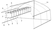
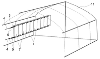
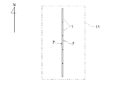
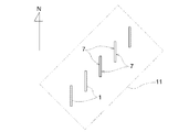
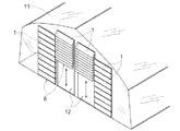
図1、図2に示すように、蓄熱カプセル1の複数を、夫々所定間隔置きに並べて連結装置4を介して連結し、それらの各蓄熱カプセル1の受熱表面7の向きを変更自在に、夫々同一方向の軸心を中心に回転自在に前記連結装置4に取り付けて蓄熱装置を構成し、温室11やサンルーム等の太陽光の照射する建築物中に設置してある。
Embodiments of the present invention will be described below with reference to the drawings.
[First Embodiment]
As shown in FIGS. 1 and 2, a plurality of
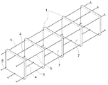
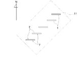
前記蓄熱装置は、連結装置4により複数の蓄熱カプセル1をそれらの受熱表面7が向き変更自在に取り付けてあるために、温室11の立地条件によって温室11そのものの設置方向が異なる場合に対応して、図5〜図8に示すように、例えば、蓄熱カプセル1を南北方向に並設しなければならない場合には(図5)、夫々の蓄熱カプセル1の受熱表面7を東西向きに設置し、例えば、蓄熱カプセル1を東西方向に並設しなければならない場合には(図6)、夫々の蓄熱カプセル1の受熱表面7を南向きに設置し、例えば、その他の斜め方向に蓄熱カプセル1並設しなければならない場合には、夫々の蓄熱カプセル1の受熱表面7を、南向きにしたり(図8)、あるいは、東西方向に向けて設置してもよい(図7)。
Since the heat storage device has a plurality of
前記蓄熱カプセル1は、主に合成樹脂や金属板などで成形された略扁平形状のカプセル容器本体2と、そのカプセル容器本体2の内部に充填する蓄熱材3とで構成してあり、例えば、日中に連結装置4によって連結された複数枚の蓄熱カプセル1の受熱表面7に太陽光が照射されるように、それぞれの蓄熱カプセル1の向きを調整して太陽熱を蓄熱し、夜間などの室内温度の低下する時間帯に、蓄熱カプセル1に蓄えられた熱エネルギーを放出して室内温度の高低差を少なくして、暖房装置などの熱エネルギーの消費を抑え、燃料費の節約とともに、省エネルギーと地球温暖化ガスの排出減少に寄与する蓄熱設備を構成してある。
The
前記カプセル容器本体2は、例えば、ポリエチレン、ポリプロピレン等の合成樹脂製の略扁平な形状の容器によって、蓄熱材3を密封状態に収容する収容部を形成してあり、その受熱表面7を凹凸上に構成して表面積の増加を図り、熱交換効率の向上を実現できるように構成されている。
The
前記蓄熱材3は、例えば、塩化カルシウム水和物と水との混合物、あるいは、低融点の各種プラスチック、パラフィン類、ワックスなど熱の吸収・放出に伴って相変態する潜熱を利用する材料を用いて構成することができる。例えば、前記蓄熱カプセル1を温室11などの空間に使用する場合には、太陽熱を蓄熱カプセル1に蓄熱する場合が考えられる。この時、前記潜熱を利用する材料の場合には、室内温度がおよそ5℃〜35℃の間で変動すると想定して、例えば23℃前後の温度において相変態可能なものを用いることが一例として挙げられる。
ただし、温室11内で栽培する植物の適切環境温度は、夫々異なるもので、そのために、それらの栽培植物に応じて相変態する温度の異なる蓄熱材3を収容した蓄熱カプセル1を複数枚連結した蓄熱装置を、温室11内で取り換えできるようにしてあってもよい。
The heat storage material 3 is, for example, a mixture of calcium chloride hydrate and water, or a material that uses latent heat that undergoes phase transformation with heat absorption / release, such as various low melting point plastics, paraffins, and waxes. Can be configured. For example, when the
However, the appropriate environmental temperatures of the plants cultivated in the
蓄熱材3の潜熱を利用する場合には、熱の吸収・排出量を大きく確保することができる。また、潜熱に替えて、顕熱を利用する物質を蓄熱材3として使用することも可能である。 When the latent heat of the heat storage material 3 is used, a large amount of heat absorption / discharge can be secured. Further, instead of latent heat, a substance that utilizes sensible heat can be used as the heat storage material 3.
前記蓄熱装置には、複数の前記蓄熱カプセル1の受熱表面7を同時に同一方向に向き変更操作自在にする連携操作機構5を設けて、複数の前記蓄熱カプセル1の受熱表面7が、同一面上に並ぶ第1姿勢(図2)と、並設方向と交差する第2姿勢(図1)とに向き変更操作自在にしてある。
従って、太陽光からの熱を効率よく受熱しやすく、しかも、連携操作機構5により、第1姿勢にすれば、複数の蓄熱カプセル1全体で大きな受熱面積を確保してより多くの太陽熱を蓄熱でき、また、第2姿勢に切り換えることで、並設する蓄熱カプセル1間を通気路や太陽光の透過路に形成でき、従って、室内における環境を簡単に変更できる。
The heat storage device is provided with a
Accordingly, it is easy to efficiently receive heat from sunlight, and if the
[第2実施形態]
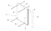
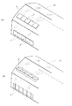
前記蓄熱装置を、図9(a)、(b)に示すように、建物の壁面の少なくとも一部に設置し、複数の前記蓄熱カプセル1の受熱表面7が、同一面上に並ぶ第1姿勢にすることにより(図9(a))、室内を密閉する閉塞状態になると共に、前記第2姿勢にすることにより(図9(b))、外気と室内とが連通する換気状態になるように状態切り換え自在にしてある。
これにより、蓄熱装置が太陽熱エネルギーの蓄熱と、換気窓の役目の両方を兼用できる温室11が構成され、室内の温度調整の自由度が向上する。
[Second Embodiment]
As shown in FIGS. 9A and 9B, the heat storage device is installed on at least a part of the wall surface of the building, and the
Thereby, the
[第3実施形態]
前記蓄熱装置を、図10に示すように、温室11や倉庫の壁面の少なくとも1部に設置し、前記第2姿勢において、並設した複数の蓄熱カプセル1夫々の間隔を伸縮自在にする並設間隔変更機構6を設け、並設した複数の蓄熱カプセル1夫々の間隔を収縮させた壁面開口部形成状態と、並設した複数の蓄熱カプセル1夫々の間隔を伸長させた隔壁形成状態とに切り換え自在に構成してある。
従って、壁面開口部形成状態にした時に、温室11に対しては農作業機や植物栽培材料の出し入れを可能にし、倉庫に対しては、保管品の出し入れのための出入り口12になり、隔壁形成状態にした時には、太陽光エネルギーの蓄熱および放熱のためのエネルギー対策設備になる。
[Third Embodiment]
As shown in FIG. 10, the heat storage device is installed on at least a part of the wall surface of the
Accordingly, when the wall surface opening is formed, the agricultural machine and the plant cultivation material can be taken in and out of the
〔別実施形態〕
以下に他の実施の形態を説明する。
[Another embodiment]
Other embodiments will be described below.
〈1〉 蓄熱装置には、連携操作機構5を設けずに、複数の蓄熱カプセル1を、夫々手動でそれらの受熱表面7の向きを変更するように構成してあってもよい。
〈2〉 カプセル容器本体2は、合成樹脂製に代えて、ステンレス鋼や普通鋼、アルミニウム、銅、金属と合成樹脂とのラミネート等の薄膜で構成するものでもよい。
〈3〉 蓄熱カプセル1夫々を、図11に示すように、受熱表面7とは反対の裏面に、発泡ポリエチレンや発泡スチロール等の発泡樹脂や、合成樹脂や無機材から成る繊維マットの断熱層8を設けてあってもよい。
〈4〉 蓄熱カプセル1夫々を、受熱表面7とは反対の裏面に、熱線反射層9を設けてあってもよい(図12)。
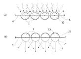
〈5〉 前記蓄熱カプセル1を、図13(a)、(b)に示すように、夫々回転軸心に沿った方向視で丸い形状又は多角形状の柱状に形成し、前記蓄熱カプセル1を、夫々カプセル並設方向と交差する同一方向の軸心を中心に回転自在に前記連結装置4に取り付け、前記蓄熱カプセル1の径方向における一方側に受熱表面7を形成すると共に、他方側に熱線反射表面13を形成し、複数の前記蓄熱カプセル1の受熱表面7が、前記連携操作機構5によって各軸心回りに180度向き変更操作自在(図13(a)→(b))にしてあってもよい。
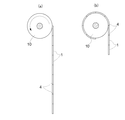
〈6〉 前記連結装置4によって連結された複数の蓄熱カプセル1を、図14(a)、(b)に示すように、それらの並設方向に巻き取り自在な巻取り収納機構10を設けてあってもよい。この巻取り収納機構10により、建物の開口部を形成したり、ブラインドのように、蓄熱の必要な時にのみ複数の蓄熱カプセル1を上下に並べて、蓄熱ができるようにしてあってもよい。
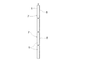
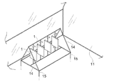
〈7〉 図15に示すように、温室11内に設置する蓄熱装置として、温室の地面に突き刺して安定に設置した脚部15を、下端部に備えたパイプ状の支持フレーム14を設け、その支持フレーム14に複数の蓄熱カプセル1を、前後の所定間隔置きに支持フレーム14に取り付けた縦支持パイプ16に、軸心回りに回転自在に取り付けてあるものでもよい。この時の蓄熱カプセル1は、夫々手動で回転操作するもので、これに代え、前述の連携操作機構を設けて同時に複数の蓄熱カプセル1を回転操作可能な構成にしてあっても良い。
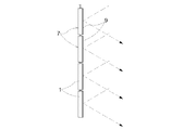
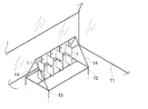
〈8〉 図16は、図15の構造の更なる改良で、縦支持フレーム14夫々に、上下複数個ずつ蓄熱カプセル1を取り付けてあって、夫々が縦軸心周りに回転自在にしてある。また、蓄熱カプセル1をその上下に取り付ける数は、2個以上であっても良い。
<1> In the heat storage device, the plurality of
<2> The
<3> As shown in FIG. 11, each
<4> Each of the
<5> As shown in FIGS. 13A and 13B, the
<6> A plurality of
<7> As shown in FIG. 15, as a heat storage device installed in the
<8> FIG. 16 is a further improvement of the structure of FIG. 15, in which a plurality of upper and lower
尚、上述のように、図面との対照を便利にするために符号を記したが、該記入により本発明は添付図面の構成に限定されるものではない。また、本発明の要旨を逸脱しない範囲において、種々なる態様で実施し得ることは勿論である。 In addition, as mentioned above, although the code | symbol was written in order to make contrast with drawing convenient, this invention is not limited to the structure of an accompanying drawing by this entry. In addition, it goes without saying that the present invention can be carried out in various modes without departing from the gist of the present invention.
1 蓄熱カプセル
4 連結装置
5 連携操作機構
6 並設間隔変更機構
7 受熱表面
8 断熱層
9 熱線反射層
10 巻取り収納機構
DESCRIPTION OF
Claims (10)
それらの各蓄熱カプセルの受熱表面の向きを変更自在に、夫々同一方向の軸心を中心に回転自在に前記連結装置に取り付けてある蓄熱装置。 A plurality of heat storage capsules are arranged at predetermined intervals and connected via a connecting device,
A heat storage device that is attached to the coupling device so that the direction of the heat receiving surface of each of the heat storage capsules can be freely changed, and is rotatable about an axis in the same direction.
前記蓄熱カプセルを、夫々カプセル並設方向と交差する同一方向の軸心を中心に回転自在に前記連結装置に取り付け、
複数の前記蓄熱カプセルの受熱表面が、同一面上に並ぶ第1姿勢と、並設方向と交差する第2姿勢とに前記連携操作機構によって向き変更操作自在にしてある請求項2に記載の蓄熱装置。 Each of the heat storage capsules is formed into a flat shape,
The heat storage capsule is attached to the coupling device so as to be rotatable around an axis in the same direction intersecting the capsule juxtaposition direction, respectively.
The heat storage according to claim 2, wherein the heat receiving surfaces of the plurality of heat storage capsules are freely changeable in direction by the cooperative operation mechanism between a first posture arranged on the same plane and a second posture intersecting the juxtaposed direction. apparatus.
前記蓄熱カプセルを、夫々カプセル並設方向と交差する同一方向の軸心を中心に回転自在に前記連結装置に取り付け、
前記蓄熱カプセルの径方向における一方側に受熱表面を形成すると共に、他方側に熱線反射表面を形成し、
複数の前記蓄熱カプセルの受熱表面が、前記連携操作機構によって各軸心回りに180度向き変更操作自在にしてある請求項2に記載の蓄熱装置。 Each of the heat storage capsules is formed into a round or polygonal columnar shape in a direction view along the rotation axis,
The heat storage capsule is attached to the coupling device so as to be rotatable around an axis in the same direction intersecting the capsule juxtaposition direction, respectively.
Forming a heat receiving surface on one side in the radial direction of the heat storage capsule and forming a heat ray reflective surface on the other side;
The heat storage device according to claim 2, wherein the heat receiving surfaces of the plurality of heat storage capsules are freely changeable in the direction of 180 degrees around each axis by the cooperative operation mechanism.
並設間隔変更機構によって、並設した複数の蓄熱カプセル夫々の間隔を収縮させた壁面開口部形成状態と、並設した複数の蓄熱カプセル夫々の間隔を伸長させた隔壁形成状態とに切り換え自在にしてある蓄熱装置の設置構造。 The heat storage device according to claim 4 is installed on at least a part of the wall surface of the building,
The parallel arrangement interval changing mechanism allows switching between a wall surface opening state in which the intervals between the plurality of heat storage capsules arranged in parallel are contracted and a partition wall formation state in which the intervals between the plurality of heat storage capsules arranged in parallel are extended. The installation structure of a heat storage device.
Priority Applications (1)
| Application Number | Priority Date | Filing Date | Title |
|---|---|---|---|
| JP2016147272A JP2018017444A (en) | 2016-07-27 | 2016-07-27 | Thermal storage device and installation structure of thermal storage device |
Applications Claiming Priority (1)
| Application Number | Priority Date | Filing Date | Title |
|---|---|---|---|
| JP2016147272A JP2018017444A (en) | 2016-07-27 | 2016-07-27 | Thermal storage device and installation structure of thermal storage device |
Publications (1)
| Publication Number | Publication Date |
|---|---|
| JP2018017444A true JP2018017444A (en) | 2018-02-01 |
Family
ID=61076041
Family Applications (1)
| Application Number | Title | Priority Date | Filing Date |
|---|---|---|---|
| JP2016147272A Pending JP2018017444A (en) | 2016-07-27 | 2016-07-27 | Thermal storage device and installation structure of thermal storage device |
Country Status (1)
| Country | Link |
|---|---|
| JP (1) | JP2018017444A (en) |
Cited By (1)
| Publication number | Priority date | Publication date | Assignee | Title |
|---|---|---|---|---|
| JP2024091783A (en) * | 2021-08-17 | 2024-07-05 | 株式会社神戸製鋼所 | Agricultural House |
Citations (13)
| Publication number | Priority date | Publication date | Assignee | Title |
|---|---|---|---|---|
| JPS56109394U (en) * | 1980-01-22 | 1981-08-25 | ||
| JPS5733951U (en) * | 1980-08-04 | 1982-02-23 | ||
| JPS57150199U (en) * | 1981-03-16 | 1982-09-21 | ||
| JPS5827498U (en) * | 1981-08-18 | 1983-02-22 | 昭和アルミニウム株式会社 | roll-up blinds |
| JPS5846048U (en) * | 1981-09-22 | 1983-03-28 | 昭和アルミニウム株式会社 | Heating device using sunlight transmission room |
| JPS5949144U (en) * | 1982-09-21 | 1984-04-02 | 大和ハウス工業株式会社 | heat storage bay window |
| JPS5991549U (en) * | 1982-12-13 | 1984-06-21 | 積水化学工業株式会社 | heat storage device |
| JPS59157437A (en) * | 1983-02-24 | 1984-09-06 | Matsushita Electric Works Ltd | Window heat insulating device |
| JPS61155589U (en) * | 1985-03-19 | 1986-09-26 | ||
| JPS6229864A (en) * | 1985-07-30 | 1987-02-07 | Matsushita Electric Ind Co Ltd | Solar heating system |
| JPS6263392U (en) * | 1985-10-14 | 1987-04-20 | ||
| JP4614705B2 (en) * | 2004-06-17 | 2011-01-19 | 株式会社ヤノ技研 | Heat storage block body and heat storage tank |
| US20110198052A1 (en) * | 2007-12-10 | 2011-08-18 | Stephen Glyn Bourne | Wall or roof of a building with at least one heat controlling element |
-
2016
- 2016-07-27 JP JP2016147272A patent/JP2018017444A/en active Pending
Patent Citations (13)
| Publication number | Priority date | Publication date | Assignee | Title |
|---|---|---|---|---|
| JPS56109394U (en) * | 1980-01-22 | 1981-08-25 | ||
| JPS5733951U (en) * | 1980-08-04 | 1982-02-23 | ||
| JPS57150199U (en) * | 1981-03-16 | 1982-09-21 | ||
| JPS5827498U (en) * | 1981-08-18 | 1983-02-22 | 昭和アルミニウム株式会社 | roll-up blinds |
| JPS5846048U (en) * | 1981-09-22 | 1983-03-28 | 昭和アルミニウム株式会社 | Heating device using sunlight transmission room |
| JPS5949144U (en) * | 1982-09-21 | 1984-04-02 | 大和ハウス工業株式会社 | heat storage bay window |
| JPS5991549U (en) * | 1982-12-13 | 1984-06-21 | 積水化学工業株式会社 | heat storage device |
| JPS59157437A (en) * | 1983-02-24 | 1984-09-06 | Matsushita Electric Works Ltd | Window heat insulating device |
| JPS61155589U (en) * | 1985-03-19 | 1986-09-26 | ||
| JPS6229864A (en) * | 1985-07-30 | 1987-02-07 | Matsushita Electric Ind Co Ltd | Solar heating system |
| JPS6263392U (en) * | 1985-10-14 | 1987-04-20 | ||
| JP4614705B2 (en) * | 2004-06-17 | 2011-01-19 | 株式会社ヤノ技研 | Heat storage block body and heat storage tank |
| US20110198052A1 (en) * | 2007-12-10 | 2011-08-18 | Stephen Glyn Bourne | Wall or roof of a building with at least one heat controlling element |
Cited By (3)
| Publication number | Priority date | Publication date | Assignee | Title |
|---|---|---|---|---|
| JP2024091783A (en) * | 2021-08-17 | 2024-07-05 | 株式会社神戸製鋼所 | Agricultural House |
| JP7572583B2 (en) | 2021-08-17 | 2024-10-23 | 株式会社神戸製鋼所 | Agricultural House |
| US12429250B2 (en) | 2021-08-17 | 2025-09-30 | Kobe Steel Ltd. | Heat-collecting member and agricultural house |
Similar Documents
| Publication | Publication Date | Title |
|---|---|---|
| US12193377B2 (en) | Multi-source heat exchange system employing a ground-energy storage system for controlled environment enclosures | |
| US4119084A (en) | Building with passive solar energy conditioning | |
| US2595905A (en) | Radiant energy heat transfer device | |
| US9554523B2 (en) | Passive solar greenhouse | |
| JP2014145582A (en) | Solar energy conversion | |
| US4223666A (en) | Toroidal solar collection and energy storage apparatus | |
| US12510256B2 (en) | Energy efficient enclosure temperature regulation system | |
| US4739748A (en) | Solar collector storage system and method | |
| US4497311A (en) | Sun tracking solar air heating system | |
| US11006586B2 (en) | Energy efficient greenhouse | |
| US4338917A (en) | Low temperature solar furnace and method | |
| JP2018017444A (en) | Thermal storage device and installation structure of thermal storage device | |
| CN203891495U (en) | Solar heating structure of building | |
| JP5246612B2 (en) | Solar heat daylighting and collecting / exhaust heat apparatus and its utilization method | |
| JP2005282942A (en) | Heat storage type ventilation system | |
| US4353353A (en) | Low temperature solar furnace and method | |
| JP2003202130A (en) | Heating-cooling device | |
| CN107975252B (en) | Building structure | |
| WO2018081555A1 (en) | Energy efficient building structure | |
| Ermuratskii et al. | Experimental investigation of two modified energy-saving constructions of solar greenhouses | |
| JPS6123267Y2 (en) | ||
| JPH0418365Y2 (en) | ||
| JPS649544B2 (en) | ||
| JP2014025654A (en) | Heat accumulation and radiation unit pipe | |
| US20180224157A1 (en) | Fluid solar heating system |
Legal Events
| Date | Code | Title | Description |
|---|---|---|---|
| A621 | Written request for application examination |
Free format text: JAPANESE INTERMEDIATE CODE: A621 Effective date: 20180323 |
|
| A977 | Report on retrieval |
Free format text: JAPANESE INTERMEDIATE CODE: A971007 Effective date: 20190116 |
|
| A131 | Notification of reasons for refusal |
Free format text: JAPANESE INTERMEDIATE CODE: A131 Effective date: 20190205 |
|
| A02 | Decision of refusal |
Free format text: JAPANESE INTERMEDIATE CODE: A02 Effective date: 20190820 |