JP2018013321A - Dry method and drying furnace for roughened aluminum foil - Google Patents
Dry method and drying furnace for roughened aluminum foil Download PDFInfo
- Publication number
- JP2018013321A JP2018013321A JP2016154050A JP2016154050A JP2018013321A JP 2018013321 A JP2018013321 A JP 2018013321A JP 2016154050 A JP2016154050 A JP 2016154050A JP 2016154050 A JP2016154050 A JP 2016154050A JP 2018013321 A JP2018013321 A JP 2018013321A
- Authority
- JP
- Japan
- Prior art keywords
- aluminum foil
- drying
- water
- furnace
- aluminum
- Prior art date
- Legal status (The legal status is an assumption and is not a legal conclusion. Google has not performed a legal analysis and makes no representation as to the accuracy of the status listed.)
- Granted
Links
- XAGFODPZIPBFFR-UHFFFAOYSA-N aluminium Chemical compound [Al] XAGFODPZIPBFFR-UHFFFAOYSA-N 0.000 title claims abstract description 73
- 229910052782 aluminium Inorganic materials 0.000 title claims abstract description 73
- 239000011888 foil Substances 0.000 title claims abstract description 65
- 238000001035 drying Methods 0.000 title claims abstract description 29
- 238000000034 method Methods 0.000 title claims description 12
- XLYOFNOQVPJJNP-UHFFFAOYSA-N water Substances O XLYOFNOQVPJJNP-UHFFFAOYSA-N 0.000 claims abstract description 42
- 238000010438 heat treatment Methods 0.000 claims abstract description 13
- 230000003628 erosive effect Effects 0.000 claims abstract description 9
- 239000003990 capacitor Substances 0.000 claims abstract description 7
- 238000001704 evaporation Methods 0.000 claims abstract description 7
- 238000005406 washing Methods 0.000 claims abstract description 7
- 230000008020 evaporation Effects 0.000 claims abstract description 6
- 238000004140 cleaning Methods 0.000 claims description 24
- 238000007788 roughening Methods 0.000 claims description 8
- 238000010521 absorption reaction Methods 0.000 claims description 7
- 230000005855 radiation Effects 0.000 claims description 5
- 238000007605 air drying Methods 0.000 claims 1
- 238000004904 shortening Methods 0.000 abstract 1
- 239000000126 substance Substances 0.000 description 3
- 238000006243 chemical reaction Methods 0.000 description 2
- 230000007423 decrease Effects 0.000 description 2
- 230000007774 longterm Effects 0.000 description 2
- 238000004519 manufacturing process Methods 0.000 description 2
- 239000011248 coating agent Substances 0.000 description 1
- 238000000576 coating method Methods 0.000 description 1
- 238000007599 discharging Methods 0.000 description 1
- 238000006073 displacement reaction Methods 0.000 description 1
- 239000008151 electrolyte solution Substances 0.000 description 1
- 238000005516 engineering process Methods 0.000 description 1
- 239000010408 film Substances 0.000 description 1
- 230000020169 heat generation Effects 0.000 description 1
- 229910001293 incoloy Inorganic materials 0.000 description 1
- 239000007788 liquid Substances 0.000 description 1
- 238000007254 oxidation reaction Methods 0.000 description 1
- 238000007781 pre-processing Methods 0.000 description 1
- 239000010453 quartz Substances 0.000 description 1
- VYPSYNLAJGMNEJ-UHFFFAOYSA-N silicon dioxide Inorganic materials O=[Si]=O VYPSYNLAJGMNEJ-UHFFFAOYSA-N 0.000 description 1
- 239000000243 solution Substances 0.000 description 1
- 239000010409 thin film Substances 0.000 description 1
Images


Landscapes
- Drying Of Solid Materials (AREA)
Abstract
Description
本発明は、アルミ電解コンデンサー等の製造に用いられ、表面に粗面化処理が施された後、水洗いされるアルミ箔に付着した洗浄水の乾燥方法及び乾燥炉に関する。 The present invention relates to a method and a drying furnace for drying cleaning water attached to an aluminum foil that is used for manufacturing an aluminum electrolytic capacitor or the like and subjected to a surface roughening treatment and then washed with water.
従来の乾燥装置は、粗面化処理を施したアルミ箔に付着した電解液を洗浄した後、アルミ箔を乾燥装置に移送し、電気炉、ガス炉、温風炉等によりアルミ箔を加熱してアルミ箔表面に付着する洗浄水及び粗面化処理により生じたアルミ箔表面の浸食部に残存する洗浄水の乾燥を共におこなうものであった(例えば、下記特許文献参照)。このように、アルミ箔の温度を上昇させ乾燥させる方式を、本明細書では空気加熱方式と呼ぶ。 In the conventional drying device, after washing the electrolytic solution adhering to the roughened aluminum foil, the aluminum foil is transferred to the drying device, and the aluminum foil is heated by an electric furnace, gas furnace, hot air furnace, etc. The cleaning water adhering to the surface of the aluminum foil and the cleaning water remaining in the erosion part of the surface of the aluminum foil generated by the roughening treatment are both dried (see, for example, the following patent document). In this specification, the method of raising the temperature of the aluminum foil and drying it is called an air heating method in this specification.
先行技術文献には粗面化処理を施したアルミ箔の乾燥に遠赤外線を用いる記載がない。There is no description in the prior art documents that far infrared rays are used for drying the roughened aluminum foil.
しかしながら、水洗後のアルミ箔は、表面全体を覆うように水が付着している状態である。従来の乾燥炉による空気加熱方式では、アルミ箔表面に付着する水の蒸発熱でアルミ箔の温度が低下するため、アルミ箔が乾燥に必要な温度に達するまでに長時間の加熱を必要としていた。 However, the aluminum foil after washing is in a state where water adheres so as to cover the entire surface. In the conventional air heating method using a drying furnace, the temperature of the aluminum foil decreases due to the heat of evaporation of water adhering to the surface of the aluminum foil, so it took a long time for the aluminum foil to reach the temperature required for drying. .
また、蒸発した水分が炉内に留まるため、長期間の炉の運転によって水分による炉の汚損が発生していた。 In addition, since the evaporated water stays in the furnace, the furnace is contaminated by moisture during long-term operation of the furnace.
本発明に係る乾燥方法は、アルミ電解コンデンサー等の製造において、粗面化処理を施したアルミ箔の表面に付着した洗浄水を乾燥するために、遠赤外線によってアルミ箔表面に付着した洗浄水を直接加熱し洗浄水を蒸発させる第一の工程と、第一の工程に引き続き、粗面化処理を施したアルミ箔の浸食部に残存する洗浄水を空気加熱方式により乾燥させる第二の工程とを有するアルミ箔の乾燥方法である。 In the production of an aluminum electrolytic capacitor or the like, the drying method according to the present invention uses cleaning water adhered to the surface of the aluminum foil by far infrared rays in order to dry the cleaning water adhered to the surface of the aluminum foil that has been subjected to the roughening treatment. A first step of directly heating and evaporating the cleaning water; and a second step of drying the cleaning water remaining in the eroded portion of the aluminum foil subjected to the roughening treatment by an air heating method following the first step. A method for drying an aluminum foil having
また、本発明に係る乾燥炉は、前記第一の工程において用いられる乾燥炉において、遠赤外線ヒータを有する。この遠赤外線ヒータによって、水の最大吸収波長である3μm近傍の波長の輻射を生ぜしめ、これにより、アルミ箔表面に付着した洗浄水を、アルミ箔からの熱伝導ではなく、直接加熱することを可能にする。 Moreover, the drying furnace which concerns on this invention is a drying furnace used in said 1st process, and has a far-infrared heater. This far-infrared heater generates radiation with a wavelength in the vicinity of 3 μm, which is the maximum absorption wavelength of water, so that the cleaning water adhering to the surface of the aluminum foil can be directly heated rather than heat conduction from the aluminum foil. to enable.
好ましくは、本発明に係る乾燥炉は洗浄水を直接加熱することによって発生する水蒸気を炉外部に排出する構造を有する。 Preferably, the drying furnace according to the present invention has a structure for discharging water vapor generated by directly heating the cleaning water to the outside of the furnace.
本発明によれば、上記第一の工程でアルミ箔の表面に存在する比較的多量の洗浄水を直接加熱することにより効率良く蒸発除去させ、その後上記第二の工程にアルミ箔を移送してアルミ箔の浸食部を、アルミ箔自体の温度を上昇させることにより乾燥する。そのため、上記第二の工程において表面に存在する洗浄水の蒸発熱によりアルミ箔の温度が低下することなく必要温度を得ることが可能となり、乾燥処理時間を短縮することができる。 According to the present invention, a relatively large amount of cleaning water present on the surface of the aluminum foil in the first step is directly evaporated and removed by evaporation, and then the aluminum foil is transferred to the second step. The eroded portion of the aluminum foil is dried by increasing the temperature of the aluminum foil itself. Therefore, the required temperature can be obtained without lowering the temperature of the aluminum foil due to the evaporation heat of the cleaning water present on the surface in the second step, and the drying process time can be shortened.
以下、本発明の実施例を図面を用いて説明する。本実施例においては、空気加熱方式による乾燥炉(上記第二の工程)の直前に、遠赤外線ヒータを有する前処理機構(上記第一の工程)を接続することで、本発明の機能を実現するものである。 Embodiments of the present invention will be described below with reference to the drawings. In this embodiment, the function of the present invention is realized by connecting a pre-processing mechanism (the first step) having a far-infrared heater immediately before the drying furnace by the air heating method (the second step). To do.
図1ないし図3において、1はアルミ箔であり、アルミ純度99.99%、幅500mm、厚み0.2mmでロール状に巻いてあり、表面に粗面化処理が施されている。 1 to 3,
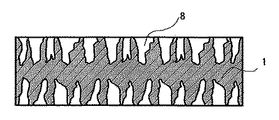
粗面化処理をおこなったアルミ箔1は陽酸化被膜処理が施されアルミ箔1に絶縁薄膜を形成させている。 図3はこのような処理後のアルミ箔1の断面を模式的に表したアルミ箔浸食部の説明図であり、アルミ箔1表面には微細な浸食部8が多数形成されている。 The
図1、図2において、ロールから巻き戻されたアルミ箔1は、洗浄水6により表面及び浸食部8に存在する陽酸化被膜処理液が除去される。 In FIG. 1 and FIG. 2, the
洗浄水6により付着した陽酸化被膜処理液が除去されたアルミ箔1は、前処理機構4に移送され、遠赤外線ヒータ5によりアルミ箔1の表面に付着した洗浄水を加熱して乾燥する。 使用する遠赤外線ヒータ5の輻射波長は、洗浄水6の最大吸収波長である3μm近辺であることが望ましい。 The
ここで、その根拠を説明する。渡辺敦夫、清水賢による論文、“食品工業における電磁波の知用(1)”(化学技術誌MOL、pp120−128、昭和63年2月)には、水の赤外線吸収波長依存性が記載されている。これは、水の吸収波長に関し、水層の厚さ変化による吸収波長の変化が記述されているものである。これによれば、波長3μmを中心とし±0.2μmでの吸収率が高く、これに対応する温度は、“ウィーンの変位側”(黒体からの輻射のピークの波長が温度に反比例する法則)より
λm=(3±0.2)μm=2.896/(T±273)より
T=632℃≦T≦761℃が求められる。
よって使用する発熱体の温度は、この温度範囲内またはこの近傍であることが望ましく、更に遠赤外線ヒータの発熱温度と消費電力が比例することから電力消費量が少なくなる、632℃近傍に遠赤外線ヒータの発熱温度を設定することが望ましい。Here, the grounds will be described. In the paper by Ikuo Watanabe and Ken Shimizu, “Use of electromagnetic waves in the food industry (1)” (Chemical Technology Journal, MOL, pp120-128, February 1988), the infrared absorption wavelength dependence of water is described. Yes. This describes the change in the absorption wavelength due to the change in the thickness of the water layer with respect to the absorption wavelength of water. According to this, the absorptance is high at ± 0.2 μm centered on a wavelength of 3 μm, and the temperature corresponding to this is the “Vienna displacement side” (a law in which the wavelength of the peak of radiation from a black body is inversely proportional to the temperature. ) From λm = (3 ± 0.2) μm = 2.896 / (T ± 273), T = 632 ° C. ≦ T ≦ 761 ° C. is obtained.
Therefore, the temperature of the heating element to be used is preferably within this temperature range or in the vicinity thereof, and further, since the heat generation temperature of the far-infrared heater and the power consumption are proportional, the power consumption is reduced. It is desirable to set the heating temperature of the heater.
本実施例では旭電熱製作所製遠赤外線ヒータ:石英管(定格127V/1.2KW)をアルミ箔1の送り方向に対し直角に交わる方向に上部1本、下部2本の計3本用い、遠赤外線ヒータ表面温度は630℃となるように設定した。前処理機構4の内部温度は300℃、アルミ箔1の表面温度は400℃である。 In this embodiment, a far-infrared heater manufactured by Asahi Denshi Seisakusho Co., Ltd .: a quartz tube (rated 127 V / 1.2 kW) is used with a total of three, one upper part and two lower parts in a direction perpendicular to the feeding direction of the
このような構成によれば、アルミ箔1の表面に付着した洗浄水を直接加熱して蒸発・乾燥するため、前処理機構4はその内部温度を高温に保つ必要がない。したがって、本来ならば内部温度低下の原因となる水蒸気の排出口7を設けることが可能となる。 According to such a configuration, the cleaning water adhering to the surface of the
本実施例では、排出口7は前処理機構4の上面に形成し、アルミ箔1の送り方向に対し直角方向に長さ500mm、幅20mmのスリット状とした。これにより、アルミ箔1の表面に付着した洗浄水を加熱した際に発生する水蒸気は、排出口7から効果的に排出される。 In this embodiment, the
アルミ箔1の表面を乾燥した後、アルミ箔1を本体機構2に移送して、粗面化処理により生じた浸食部8の乾燥をおこなう。 After the surface of the
本体機構2は、シーズヒータ3を用いて、空気加熱方式でアルミ箔1を加熱して、本体機構2の内部温度を570℃とし、アルミ箔1の浸食部8に残存する洗浄液を蒸発させ乾燥する。本体機構2内部の加熱には富岡産業株式会社製シーズヒータ:インコロイ800(定格127V/750W)を使用し、アルミ箔1の送り方向に対して直角となる方向に上下9本ずつ、計18本使用した。シーズヒータの温度は800℃に設定した。 The
本実施例ではアルミ箔1の表面に付着した洗浄水は前処理機構4により予め乾燥させる。そのため、本体機構2でアルミ箔1を加熱する際、従来例でのようにアルミ箔1の表面に付着する洗浄水が蒸発する際の蒸発熱による温度低下が生じない。したがって、必要な温度を維持することが容易に可能となり、アルミ箔1の乾燥時間の短縮を図ることができる。 In this embodiment, the cleaning water adhering to the surface of the
本実施例の乾燥炉では、従来のアルミ箔1の移送速度1.0m/minを、2.0m/minに上昇させることが可能となり、単位長あたりの使用電力を20%減少させることが可能となる。 In the drying furnace of the present embodiment, the transfer speed of the
また、本実施例では前処理機構4において排出口7により水蒸気が排出されているので、長期間の運転においても本体機構2の内部が水分で汚損されることがない。 Further, in the present embodiment, since the water vapor is discharged from the
なお、排出口7の形状としては、上述したスリット状以外でも、連続する複数の開口部からなるものであっても良い。 In addition, as a shape of the
また、本体機構2と前処理機構4は、一体となった構造であっても、分離された構造であっても良い。 Further, the
1 アルミ箔、 2 本体機構、 3 シーズヒータ、 4 前処理機構
5 遠赤外線ヒータ、 6 洗浄水、 7 排出口、 8 浸食部DESCRIPTION OF
Claims (3)
Priority Applications (1)
| Application Number | Priority Date | Filing Date | Title |
|---|---|---|---|
| JP2016154050A JP6775186B2 (en) | 2016-07-19 | 2016-07-19 | Drying method and drying furnace for roughened aluminum foil |
Applications Claiming Priority (1)
| Application Number | Priority Date | Filing Date | Title |
|---|---|---|---|
| JP2016154050A JP6775186B2 (en) | 2016-07-19 | 2016-07-19 | Drying method and drying furnace for roughened aluminum foil |
Publications (2)
| Publication Number | Publication Date |
|---|---|
| JP2018013321A true JP2018013321A (en) | 2018-01-25 |
| JP6775186B2 JP6775186B2 (en) | 2020-10-28 |
Family
ID=61020200
Family Applications (1)
| Application Number | Title | Priority Date | Filing Date |
|---|---|---|---|
| JP2016154050A Active JP6775186B2 (en) | 2016-07-19 | 2016-07-19 | Drying method and drying furnace for roughened aluminum foil |
Country Status (1)
| Country | Link |
|---|---|
| JP (1) | JP6775186B2 (en) |
Cited By (2)
| Publication number | Priority date | Publication date | Assignee | Title |
|---|---|---|---|---|
| CN114992994A (en) * | 2022-05-25 | 2022-09-02 | 黄山天马铝业有限公司 | Surface coating and drying device for aluminum foil production |
| CN115787022A (en) * | 2022-10-25 | 2023-03-14 | 江苏荣生电子有限公司 | Formation device for processing electrode foil |
Citations (4)
| Publication number | Priority date | Publication date | Assignee | Title |
|---|---|---|---|---|
| JPS579098U (en) * | 1980-05-30 | 1982-01-18 | ||
| JPH01116094U (en) * | 1988-01-30 | 1989-08-04 | ||
| JP2000329463A (en) * | 1999-05-14 | 2000-11-30 | Konica Corp | Method and equipment for drying coat |
| JP2016040496A (en) * | 2014-08-12 | 2016-03-24 | 日本碍子株式会社 | Infrared ray processing device |
-
2016
- 2016-07-19 JP JP2016154050A patent/JP6775186B2/en active Active
Patent Citations (4)
| Publication number | Priority date | Publication date | Assignee | Title |
|---|---|---|---|---|
| JPS579098U (en) * | 1980-05-30 | 1982-01-18 | ||
| JPH01116094U (en) * | 1988-01-30 | 1989-08-04 | ||
| JP2000329463A (en) * | 1999-05-14 | 2000-11-30 | Konica Corp | Method and equipment for drying coat |
| JP2016040496A (en) * | 2014-08-12 | 2016-03-24 | 日本碍子株式会社 | Infrared ray processing device |
Cited By (3)
| Publication number | Priority date | Publication date | Assignee | Title |
|---|---|---|---|---|
| CN114992994A (en) * | 2022-05-25 | 2022-09-02 | 黄山天马铝业有限公司 | Surface coating and drying device for aluminum foil production |
| CN114992994B (en) * | 2022-05-25 | 2024-03-29 | 黄山天马铝业有限公司 | Aluminum foil production is with scribbling drying device |
| CN115787022A (en) * | 2022-10-25 | 2023-03-14 | 江苏荣生电子有限公司 | Formation device for processing electrode foil |
Also Published As
| Publication number | Publication date |
|---|---|
| JP6775186B2 (en) | 2020-10-28 |
Similar Documents
| Publication | Publication Date | Title |
|---|---|---|
| KR100955540B1 (en) | heat generation sheet and fabrication method thereof | |
| JP2018013321A (en) | Dry method and drying furnace for roughened aluminum foil | |
| JP2007227831A (en) | Method and apparatus of manufacturing electrode for electrochemical element | |
| JP3650741B2 (en) | Radiation device, method of use of the device and method for treating a surface | |
| JP6274661B2 (en) | Drying equipment | |
| CN105972570B (en) | Steam generator and steaming plant | |
| CN104451556B (en) | The manufacture method of radiant type evaporation heater and the radiant type evaporation heater | |
| JP2007155310A (en) | Heat conductive assembly for water heater and manufacturing method of heat conductive assembly | |
| JP5378677B2 (en) | Ceramic heater | |
| JP6865945B2 (en) | heater | |
| EP2239365B1 (en) | Trough mangle and method for heating same | |
| Surtaev et al. | Characteristics of boiling heat transfer on hydrophilic surface with SiO2 coating | |
| TWI739985B (en) | Surface drying apparatus for sheet-like non-osmotic substrate and printing apparatus and printing method therefor | |
| JP2012241922A (en) | Batch type coating film drying furnace | |
| CN102017788A (en) | Heating-element unit, and heating device | |
| CN208525902U (en) | Quenching oil drying device | |
| KR101765471B1 (en) | Superheated steam generating apparatus for manufacturing process of secondary cell | |
| CN108684083A (en) | A kind of combined device for homogenous heating | |
| KR101108037B1 (en) | Heater assembly for Clothes Drier | |
| KR20200019359A (en) | Hair dryer using planar heater | |
| KR101110718B1 (en) | Hot Plate | |
| CN108571878A (en) | A kind of adjustable carpet drying unit of temperature | |
| US20230040167A1 (en) | Method for performing heat treatment on membrane electrode assembly | |
| WO2018000497A1 (en) | Vapour generator and vapour device | |
| JP2008039348A (en) | Microwave dryer |
Legal Events
| Date | Code | Title | Description |
|---|---|---|---|
| A521 | Request for written amendment filed |
Free format text: JAPANESE INTERMEDIATE CODE: A523 Effective date: 20161013 |
|
| A621 | Written request for application examination |
Free format text: JAPANESE INTERMEDIATE CODE: A621 Effective date: 20180914 |
|
| A977 | Report on retrieval |
Free format text: JAPANESE INTERMEDIATE CODE: A971007 Effective date: 20190716 |
|
| A131 | Notification of reasons for refusal |
Free format text: JAPANESE INTERMEDIATE CODE: A131 Effective date: 20190723 |
|
| A521 | Request for written amendment filed |
Free format text: JAPANESE INTERMEDIATE CODE: A523 Effective date: 20190919 |
|
| A131 | Notification of reasons for refusal |
Free format text: JAPANESE INTERMEDIATE CODE: A131 Effective date: 20200218 |
|
| A601 | Written request for extension of time |
Free format text: JAPANESE INTERMEDIATE CODE: A601 Effective date: 20200413 |
|
| A521 | Request for written amendment filed |
Free format text: JAPANESE INTERMEDIATE CODE: A523 Effective date: 20200602 |
|
| A521 | Request for written amendment filed |
Free format text: JAPANESE INTERMEDIATE CODE: A523 Effective date: 20200706 |
|
| TRDD | Decision of grant or rejection written | ||
| A01 | Written decision to grant a patent or to grant a registration (utility model) |
Free format text: JAPANESE INTERMEDIATE CODE: A01 Effective date: 20200901 |
|
| A61 | First payment of annual fees (during grant procedure) |
Free format text: JAPANESE INTERMEDIATE CODE: A61 Effective date: 20200918 |
|
| R150 | Certificate of patent or registration of utility model |
Ref document number: 6775186 Country of ref document: JP Free format text: JAPANESE INTERMEDIATE CODE: R150 |