JP2018013064A - Rotary compressor and manufacturing method thereof - Google Patents
Rotary compressor and manufacturing method thereof Download PDFInfo
- Publication number
- JP2018013064A JP2018013064A JP2016142260A JP2016142260A JP2018013064A JP 2018013064 A JP2018013064 A JP 2018013064A JP 2016142260 A JP2016142260 A JP 2016142260A JP 2016142260 A JP2016142260 A JP 2016142260A JP 2018013064 A JP2018013064 A JP 2018013064A
- Authority
- JP
- Japan
- Prior art keywords
- cylindrical member
- peripheral surface
- inner peripheral
- rotary compressor
- compression mechanism
- Prior art date
- Legal status (The legal status is an assumption and is not a legal conclusion. Google has not performed a legal analysis and makes no representation as to the accuracy of the status listed.)
- Pending
Links
Images


Landscapes
- Applications Or Details Of Rotary Compressors (AREA)
Abstract
Description
本発明は、ロータリ圧縮機に関する。 The present invention relates to a rotary compressor.
従来、ロータリ圧縮機では、駆動軸を駆動するモータのステータ及び圧縮機構がケーシングの内面に固定されている。例えば、特許文献1(特開2015−197046号公報)には、ステータが焼き嵌めによりケーシングの中央に固定され、圧縮機構がスポット溶接によりケーシングの下方に固定されるロータリ圧縮機が開示されている。 Conventionally, in a rotary compressor, a stator and a compression mechanism of a motor that drives a drive shaft are fixed to an inner surface of a casing. For example, Patent Document 1 (Japanese Patent Laid-Open No. 2015-197046) discloses a rotary compressor in which a stator is fixed to the center of the casing by shrink fitting and a compression mechanism is fixed to the lower portion of the casing by spot welding. .
上述した特許文献1に記載のロータリ圧縮機では、圧縮機構とケーシングとがスポット溶接により固定されているので、圧縮機構とケーシングとの間に隙間が生じることがある。そのため、この種のロータリ圧縮機では、圧縮機構の振動がケーシングに伝達し、放射音が生じることがある。
In the rotary compressor described in
本発明の課題は、放射音を低減し得るロータリ圧縮機を提供することである。 The subject of this invention is providing the rotary compressor which can reduce a radiated sound.
本発明の第1観点に係るロータリ圧縮機は、ケーシングと、駆動軸と、駆動機構と、圧縮機構と、を備える。ケーシングは、円筒部材を有する。駆動軸は、ケーシング内に配置される。駆動機構は、駆動軸に連結し、駆動軸を駆動する。圧縮機構は、駆動軸を介して駆動機構により駆動され、冷媒を圧縮する。また、圧縮機構は、円筒部材の内周面に沿って接触する固定部を有し、円筒部材の内周面に密着する状態で固定される。駆動機構は、円筒部材の内周面に隙間を空けて固定される。 A rotary compressor according to a first aspect of the present invention includes a casing, a drive shaft, a drive mechanism, and a compression mechanism. The casing has a cylindrical member. The drive shaft is disposed in the casing. The drive mechanism is coupled to the drive shaft and drives the drive shaft. The compression mechanism is driven by the drive mechanism via the drive shaft and compresses the refrigerant. In addition, the compression mechanism has a fixing portion that contacts the inner peripheral surface of the cylindrical member, and is fixed in a state of being in close contact with the inner peripheral surface of the cylindrical member. The drive mechanism is fixed to the inner peripheral surface of the cylindrical member with a gap.
第1観点に係るロータリ圧縮機では、圧縮機構が、円筒部材の内周面に密着する状態で固定されるので、圧縮機構の固定位置での剛性を高めることができる。この結果、圧縮機構からケーシングへの振動の伝達を抑制でき、圧縮機に生じる放射音を低減できる。また、駆動機構が、円筒部材の内周面に隙間を空けて固定されるので、圧縮機構に対して駆動軸の芯出しを容易に調整できる。 In the rotary compressor according to the first aspect, since the compression mechanism is fixed in close contact with the inner peripheral surface of the cylindrical member, the rigidity at the fixing position of the compression mechanism can be increased. As a result, transmission of vibration from the compression mechanism to the casing can be suppressed, and radiated sound generated in the compressor can be reduced. Further, since the drive mechanism is fixed to the inner peripheral surface of the cylindrical member with a gap, the centering of the drive shaft can be easily adjusted with respect to the compression mechanism.
本発明の第2観点に係るロータリ圧縮機は、第1観点に係るロータリ圧縮機において、圧縮機構が、冷媒が流入するシリンダと、シリンダの上方に配置されるフロントヘッドと、シリンダの下方に配置されるリアヘッドと、を備える。また、シリンダ、フロントヘッド、及びリアヘッドの少なくとも一つが、円筒部材の内周面に沿った固定部を有し、円筒部材の内周面に密着する状態で固定される。 A rotary compressor according to a second aspect of the present invention is the rotary compressor according to the first aspect, wherein the compression mechanism includes a cylinder into which the refrigerant flows, a front head disposed above the cylinder, and a lower portion of the cylinder. A rear head. Further, at least one of the cylinder, the front head, and the rear head has a fixing portion along the inner peripheral surface of the cylindrical member, and is fixed in a state of being in close contact with the inner peripheral surface of the cylindrical member.
第2観点に係るロータリ圧縮機では、シリンダ、フロントヘッド、及びリアヘッドの少なくとも一つ形状を円筒部材の内周面に密着させることで、圧縮機構の固定位置での剛性を高めることができる。 In the rotary compressor according to the second aspect, the rigidity at the fixed position of the compression mechanism can be increased by bringing at least one shape of the cylinder, the front head, and the rear head into close contact with the inner peripheral surface of the cylindrical member.
本発明の第3観点に係るロータリ圧縮機は、第1観点又は第2観点のロータリ圧縮機において、駆動機構が、駆動軸に固定されるロータと、ロータの外側に配置され、ロータを駆動するステータと、を備える。また、ステータが、円筒部材の内周面に隙間を空けて固定される。 A rotary compressor according to a third aspect of the present invention is the rotary compressor according to the first aspect or the second aspect, wherein the drive mechanism is disposed outside the rotor and the rotor fixed to the drive shaft, and drives the rotor. And a stator. The stator is fixed to the inner peripheral surface of the cylindrical member with a gap.
第3観点に係るロータリ圧縮機では、ステータが、円筒部材の内周面に隙間を空けて固定されるので、圧縮機構に対して駆動軸の芯出しを容易に調整することができる。 In the rotary compressor according to the third aspect, since the stator is fixed to the inner peripheral surface of the cylindrical member with a gap, the centering of the drive shaft can be easily adjusted with respect to the compression mechanism.
本発明の第4観点に係るロータリ圧縮機は、第1観点から第3観点のいずれかロータリ圧縮機において、円筒部材の内周面と駆動機構との隙間が、0.15〜0.30mmである。 A rotary compressor according to a fourth aspect of the present invention is the rotary compressor according to any one of the first to third aspects, wherein the clearance between the inner peripheral surface of the cylindrical member and the drive mechanism is 0.15 to 0.30 mm. is there.
第4観点に係るロータリ圧縮機では、所定の範囲で、圧縮機構に対する駆動軸の芯出しを調整できる。 In the rotary compressor according to the fourth aspect, the centering of the drive shaft with respect to the compression mechanism can be adjusted within a predetermined range.
本発明の第5観点に係るロータリ圧縮機は、第1観点から第4観点のいずれかロータリ圧縮機において、円筒部材の内周面と圧縮機構との隙間が、0.00〜0.10mmである。 A rotary compressor according to a fifth aspect of the present invention is the rotary compressor according to any one of the first to fourth aspects, wherein the clearance between the inner peripheral surface of the cylindrical member and the compression mechanism is 0.00 to 0.10 mm. is there.
第5観点に係るロータリ圧縮機では、圧縮機構が、円筒部材の内周面に密着する状態で固定できる。 In the rotary compressor according to the fifth aspect, the compression mechanism can be fixed in close contact with the inner peripheral surface of the cylindrical member.
本発明の第6観点に係るロータリ圧縮機は、第1観点から第5観点のいずれかロータリ圧縮機において、円筒部材の内周面と駆動機構とが、溶接、かしめ、又は接着剤により固定されたもの、もしくは、溶接及び接着剤又はかしめ及び接着剤により固定されたものである。 A rotary compressor according to a sixth aspect of the present invention is the rotary compressor according to any one of the first to fifth aspects, wherein the inner peripheral surface of the cylindrical member and the drive mechanism are fixed by welding, caulking, or an adhesive. Or fixed by welding and adhesive or caulking and adhesive.
第6観点に係るロータリ圧縮機では、円筒部材の内周面と駆動機構とが、溶接、かしめ、又は接着剤により固定される、もしくは、溶接及び接着剤又はかしめ及び接着剤により固定されるので、圧縮機構に対する駆動軸の芯出しを調整しながら、円筒部材の内周面に駆動機構を固定できる。 In the rotary compressor according to the sixth aspect, the inner peripheral surface of the cylindrical member and the drive mechanism are fixed by welding, caulking, or an adhesive, or are fixed by welding and an adhesive or caulking and an adhesive. The drive mechanism can be fixed to the inner peripheral surface of the cylindrical member while adjusting the centering of the drive shaft with respect to the compression mechanism.
本発明の第7観点に係るロータリ圧縮機は、第1観点から第6観点のいずれかロータリ圧縮機において、円筒部材の内周面と圧縮機構とが、圧入及び部分的な溶接により固定されたものである。 A rotary compressor according to a seventh aspect of the present invention is the rotary compressor according to any one of the first to sixth aspects, wherein the inner peripheral surface of the cylindrical member and the compression mechanism are fixed by press-fitting and partial welding. Is.
第7観点に係るロータリ圧縮機では、円筒部材の内周面と圧縮機構とが圧入及び部分的な溶接により固定されるので、円筒部材の内周面に密着する状態で圧縮機構を固定できる。 In the rotary compressor according to the seventh aspect, since the inner peripheral surface of the cylindrical member and the compression mechanism are fixed by press-fitting and partial welding, the compression mechanism can be fixed in close contact with the inner peripheral surface of the cylindrical member.
本発明の第8観点に係るロータリ圧縮機は、第1観点から第7観点のいずれかロータリ圧縮機において、円筒部材の内周面と圧縮機構とが、焼き嵌めにより固定されたものである。 A rotary compressor according to an eighth aspect of the present invention is the rotary compressor according to any one of the first to seventh aspects, in which the inner peripheral surface of the cylindrical member and the compression mechanism are fixed by shrink fitting.
第8観点に係るロータリ圧縮機では、円筒部材の内周面と圧縮機構とが焼き嵌めにより固定されるので、円筒部材の内周面に、さらに密着する状態で圧縮機構を固定できる。 In the rotary compressor according to the eighth aspect, since the inner peripheral surface of the cylindrical member and the compression mechanism are fixed by shrinkage fitting, it is possible to fix the compression mechanism in a state of being in close contact with the inner peripheral surface of the cylindrical member.
本発明の第9観点に係るロータリ圧縮機を製造する方法は、圧縮機構を、ケーシングの円筒部材の内周面に密着するように圧入及び部分的な溶接により固定する工程と、圧縮機構をケーシングに固定した後、駆動機構をケーシング内に配置する工程と、駆動機構の位置を移動して、駆動軸の軸心を調整する工程と、駆動軸の軸心を調整した後、駆動機構を溶接、かしめ、及び接着剤のいずれか一つ又はそれらの任意の組み合わせにより固定する工程と、を備える。 A method of manufacturing a rotary compressor according to a ninth aspect of the present invention includes a step of fixing a compression mechanism by press-fitting and partial welding so that the compression mechanism is in close contact with the inner peripheral surface of a cylindrical member of the casing, and the compression mechanism is a casing. After fixing to the casing, the step of arranging the drive mechanism in the casing, the step of moving the position of the drive mechanism to adjust the axis of the drive shaft, and the axis of the drive shaft are adjusted, and then the drive mechanism is welded , Caulking, and fixing with any one of the adhesives or any combination thereof.
第9観点に係る方法では、ケーシングの円筒部材の内周面に、略全周にわたって、圧入及び部分的な溶接により密着する状態で、圧縮機構を固定したロータリ圧縮機を製造するので、放射音を低減し得るロータリ圧縮機を提供できる。また、圧縮機構を固定してから、駆動軸の軸心を調整し、その後に駆動機構を固定するので、圧縮機構に対する駆動軸の芯出しを容易に調整できる。 In the method according to the ninth aspect, since the rotary compressor with the compression mechanism fixed is manufactured in a state of being in close contact with the inner peripheral surface of the cylindrical member of the casing by press-fitting and partial welding over the entire circumference, It is possible to provide a rotary compressor capable of reducing the above. Further, since the shaft center of the drive shaft is adjusted after the compression mechanism is fixed, and then the drive mechanism is fixed, the centering of the drive shaft with respect to the compression mechanism can be easily adjusted.
本発明の第10観点に係るロータリ圧縮機を製造する方法は、第9観点の方法において、固定する工程が、圧縮機構をケーシングに焼き嵌めする工程をさらに備える。 In the method of manufacturing the rotary compressor according to the tenth aspect of the present invention, in the method according to the ninth aspect, the fixing step further includes a step of shrink-fitting the compression mechanism to the casing.
第10観点に係る方法では、焼き嵌めする工程をさらに備えるので、ケーシングの円筒部材の内周面と圧縮機構との密着度を高めることができる。 In the method according to the tenth aspect, the method further includes the step of shrink fitting, so that the degree of adhesion between the inner peripheral surface of the cylindrical member of the casing and the compression mechanism can be increased.
第1観点に係るロータリ圧縮機では、圧縮機に生じる放射音を低減できる。また、圧縮機構に対して駆動軸の芯出しを容易に調整できる。 In the rotary compressor according to the first aspect, it is possible to reduce radiated sound generated in the compressor. Further, the centering of the drive shaft can be easily adjusted with respect to the compression mechanism.
第2観点に係るロータリ圧縮機では、圧縮機構の固定位置での剛性を高めることができる。 In the rotary compressor according to the second aspect, the rigidity at the fixed position of the compression mechanism can be increased.
第3観点に係るロータリ圧縮機では、圧縮機構に対して駆動軸の芯出しを容易に調整できる。 In the rotary compressor according to the third aspect, the centering of the drive shaft can be easily adjusted with respect to the compression mechanism.
第4観点に係るロータリ圧縮機では、所定の範囲で、圧縮機構に対する駆動軸の芯出しを調整できる。 In the rotary compressor according to the fourth aspect, the centering of the drive shaft with respect to the compression mechanism can be adjusted within a predetermined range.
第5観点に係るロータリ圧縮機では、圧縮機構が、円筒部材の内周面に密着する状態で固定できる。 In the rotary compressor according to the fifth aspect, the compression mechanism can be fixed in close contact with the inner peripheral surface of the cylindrical member.
第6観点に係るロータリ圧縮機では、圧縮機構に対する駆動軸の芯出しを調整しながら、円筒部材の内周面に駆動機構を固定できる。 In the rotary compressor according to the sixth aspect, the drive mechanism can be fixed to the inner peripheral surface of the cylindrical member while adjusting the centering of the drive shaft with respect to the compression mechanism.
第7観点に係るロータリ圧縮機では、圧縮機構が、円筒部材の内周面に密着する状態で固定できる。 In the rotary compressor according to the seventh aspect, the compression mechanism can be fixed in close contact with the inner peripheral surface of the cylindrical member.
第8観点に係るロータリ圧縮機では、圧縮機構が、円筒部材の内周面に、さらに密着する状態で固定できる。 In the rotary compressor according to the eighth aspect, the compression mechanism can be fixed to the inner peripheral surface of the cylindrical member so as to be further in close contact.
第9観点に係る方法では、放射音を低減し得るロータリ圧縮機を提供できる。また、圧縮機構に対する駆動軸の芯出しを容易に調整できる。 The method according to the ninth aspect can provide a rotary compressor that can reduce radiated sound. Further, the centering of the drive shaft with respect to the compression mechanism can be easily adjusted.
第10観点に係る方法では、ケーシングの円筒部材の内周面と圧縮機構との密着度を高めることができる。 In the method according to the tenth aspect, the degree of adhesion between the inner peripheral surface of the cylindrical member of the casing and the compression mechanism can be increased.
本発明の圧縮機の一実施形態に係るロータリ圧縮機100を、図面を参照しながら説明する。なお、下記の実施形態に係るロータリ圧縮機100は、本発明のロータリ圧縮機の一例にすぎず、本発明の趣旨を逸脱しない範囲で適宜変更可能である。
A
(1)ロータリ圧縮機が使用される空気調和装置の概要
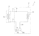
図1は本発明の一実施形態に係るロータリ圧縮機100が使用される空気調和装置1の概要図である。ここでは、冷房運転専用の空気調和装置が示されているが、ロータリ圧縮機100が採用される空気調和装置は、暖房運転専用であってもよく、冷房運転および暖房運転の両方が実施可能なものであってもよい。
(1) Outline of Air Conditioner Using Rotary Compressor FIG. 1 is a schematic view of an
空気調和装置1は、主として、ロータリ圧縮機100を有する室外ユニット2と、室内ユニット3と、室外ユニット2及び室内ユニット3を接続する液冷媒連絡配管4およびガス冷媒連絡配管5とを有する。室内ユニット3は、室内熱交換器3aを有する。室外ユニット2は、アキュムレータ6と、ロータリ圧縮機100と、室外熱交換器7と、膨張弁8とを主に有する。これらの機器が、冷媒配管により図1のように接続されて、冷媒回路10が構成される。ロータリ圧縮機100には、吸入管23を介して冷媒が吸入される。そして、ロータリ圧縮機100の圧縮室C1で冷媒が圧縮され、圧縮後の冷媒が吐出管24から吐出される。
The
(2)ロータリ圧縮機の全体構成
図2は、ロータリ圧縮機100の概略縦断面図である。以下の説明において、ロータリ圧縮機100の位置関係や方向を示すために、「上」、「下」といった表現を用いる場合があるが、特に説明がない場合、図2中の矢印Uの方向を上方向とする。
(2) Overall Configuration of Rotary Compressor FIG. 2 is a schematic longitudinal sectional view of the
ロータリ圧縮機100は、冷媒回路10の低圧の冷媒を吸入して圧縮し、高圧になった冷媒を冷媒回路10に吐出する機器である。ロータリ圧縮機100には、冷媒として例えばR32が使用される。ただし、冷媒の種類は、これに限定されるものではない。
The
ロータリ圧縮機100は、例えば図2に示すように、1シリンダ型のロータリ圧縮機である。ロータリ圧縮機100は、ケーシング20と、モータ30と、駆動軸40と、圧縮機構50と、を主に備えている。ケーシング20には、モータ30と、駆動軸40と、圧縮機構50とが収容されている。ケーシング20内には、モータ30がケーシング20の上下方向における中央部付近に配置され、その下方に圧縮機構50が配置される。
The
(3)ロータリ圧縮機の詳細構成
(3−1)ケーシング
ケーシング20は、縦型円筒状の容器である。ケーシング20は、上下が開口した円筒状の円筒部材21と、円筒部材21の上端および下端にそれぞれ設けられ、円筒部材21の上下の開口端を閉じる椀状の上蓋22aおよび下蓋22bと、を有する。円筒部材21と、上蓋22aおよび下蓋22bとは、気密を保つように溶接により固定される。
(3) Detailed configuration of the rotary compressor (3-1) Casing The
円筒部材21の下部には、圧縮機構50と連結される吸入管23が設けられる。吸入管23は、冷媒回路10から圧縮機構50内に(具体的には、後述する圧縮機構50の圧縮室C1に)、冷媒回路10における低圧冷媒を供給する。また、円筒部材21の上部には、吐出管24が設けられる。吐出管24は、圧縮機構50により圧縮された高圧冷媒を図示しない冷媒回路10に吐出する。
A
ケーシング20の下部には、油溜空間25が形成される。油溜空間25には、圧縮機構50等を潤滑するための冷凍機油Lが貯留される。
An
(3−2)モータ
モータ30は、駆動軸40に連結し、駆動軸40及び圧縮機構50を駆動する機構である。モータ30は、図2に示すように、ケーシング20の上下方向における中央部に収容される。モータ30は、圧縮機構50の上方に配置される。
(3-2) Motor The
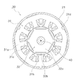
図3は、モータ30の構成を模式的に示す平面図である。モータ30は、主として、ステータ31と、ロータ32とを有する。
FIG. 3 is a plan view schematically showing the configuration of the
ステータ31は、環状に形成されており、円筒形状のステータコア31aと、このステータコア31aに巻き付けられた巻線31bとを有する。ステータコア31aは、例えば積層された複数の鋼板からなる。巻線31bは、ステータコア31aの各ティース部31cにそれぞれ巻かれるものである。ステータ31は、円筒部材21の内周面に隙間を空けて固定される。具体的には、ステータ31は、その外周面が、円筒部材21の内面とスポット溶接により固定される。ただし、ステータ31と円筒部材21との固定方法は例示であって、これに限定されるものではない。例えば、円筒部材21の内周面とステータ31とは、溶接、かしめ、又は接着剤により固定されてもよいし、溶接及び接着剤又はかしめ及び接着剤により固定されてもよい。また、円筒部材21の内周面とステータ31との隙間は、概ね0.15〜0.30mmである。
The
なお、図3に示されるように、ケーシング20の円筒部材21の内周面とステータコア31aの外周面との間には、コアカット31dが形成される。ここでは、3個のコアカット31dが形成されている。コアカット31dは、上端面から下端面に亘り中心軸に沿って形成される切欠状の溝であり、冷媒ガス及び冷凍機油の流通経路として機能する。円筒部材21の内周面とコアカット31dとの間は、概ね数mm〜数十mmである。このようなコアカット31dが形成される位置においては、上述した固定方法による、円筒部材21の内周面とステータ31の外周面との固定は除かれる。
As shown in FIG. 3, a
ロータ32は、円筒状の部材であり、ロータコア32aと、このロータコア32aに埋設された複数の磁石32bとを有する。ロータコア32aは、例えば積層された電磁鋼板からなる。また、ロータコア32aの中央の孔部には駆動軸40が挿嵌される。複数の磁石32bは、ロータコア32aの周方向に等間隔の中心角度で配列される。ロータ32は、環状に形成されたステータ31の内側に、ステータ31とわずかな隙間を隔てて配置される。そして、ロータ32は、ステータ31に巻き付けられた巻線31bに電流が流れることで発生する磁力を受けて回転する。ロータ32が回転すると、駆動軸40が回転し、駆動軸40を介して、モータ30から圧縮機構50に駆動力が伝達される。
The
(3−3)駆動軸
駆動軸40は、ケーシング20内に配置され、上下方向に延びる部材である。駆動軸40の上部は、モータ30のロータ32に連結される。駆動軸40の下部は、圧縮機構50に連結される。また、駆動軸40は、駆動軸40の軸心Oに対して偏心する偏心部41を有する。偏心部41は、ピストン61に連結される。ピストン61は、後述する圧縮機構50のシリンダ51のシリンダ孔51dに囲まれた空間に配置される。また、偏心部41は、モータ30の力を伝達可能な状態で、円筒状のピストン61の内部に嵌っている。
(3-3) Drive shaft The
駆動軸40は、後述する圧縮機構50の、フロントヘッド52の上部軸受部52aおよびリアヘッド53の下部軸受部53aによって、回転自在に支持される。駆動軸40は、モータ30が駆動されると、軸心O周りに回転する。そして、偏心部41が、軸心Oに対して偏心回転し、圧縮機構50のピストン61を公転させる。
The
駆動軸40の下端部には、油溜空間25の冷凍機油Lを吸引するための油ポンプ42が固定される。駆動軸40の内部には、油ポンプ42によって吸引された冷凍機油Lが流れる給油通路43が形成される(図2参照)。給油通路43は、駆動軸40に沿って上下方向に延びる主給油通路43aを有する。また、給油通路43は、主給油通路43aから駆動軸40の径方向外方へ延びる複数の副給油通路(図示せず)を有する。副給油通路は、上部軸受部52aの下端付近、下部軸受部53aの上端付近、および偏心部41において駆動軸40の側面に開口し、複数の給油口43bを形成する。油溜空間25から、油ポンプ42によって吸引された冷凍機油Lは、主給油通路43aおよび副給油経路を通過して、給油口43bから駆動軸40やピストン61の各摺動部に供給される。
An
(3−4)圧縮機構
圧縮機構50は、図4に示すように、シリンダ51、フロントヘッド52、及びリアヘッド53を有する。
(3-4) Compression Mechanism The
圧縮機構50は、吸入管23を介して吸入した冷媒を圧縮する機構である。圧縮機構50は、図2に示すように、モータ30の下方に配置される。圧縮機構50は、シリンダ51、フロントヘッド52、リアヘッド53、ピストン61、ブレード62、およびブッシュ63、を主に有する(図2,4,5参照)。ここで、ピストン61およびブレード62は、一体的に形成される。具体的には、ブレード62が、円筒状のピストン61の外周面61aから延びて形成される。
The
(3−4−1)シリンダ
シリンダ51は冷媒が流入する部材である。シリンダ51は、軸方向が上下方向に延びるようにケーシング20の内部に配置される。シリンダ51は、上下両端が開口しており、内部に円柱状のシリンダ孔51d(円筒形状のシリンダ51の中空部)が形成される。シリンダ孔51dには、ピストン61が収納される。
(3-4-1) Cylinder The
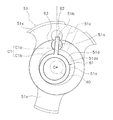
シリンダ51の、シリンダ孔51dの外周側には、ブッシュ63が回転自在に挿入されたブッシュ保持孔51a、および、ブッシュ保持孔51aに連通する給油孔51bが形成される(図5参照)。また、シリンダ51には、シリンダ孔51dに連通する吸入通路51cが形成される(図5参照)。
A
ブッシュ保持孔51aおよび給油孔51bの内部には、後述するピストン61の偏心回転に応じて、ブッシュ保持孔51aに配置されたブッシュ63により揺動可能に支持されたブレード62が出入りする。給油孔51bは、後述する、シリンダ51の下方の開口を閉塞するリアヘッド53に形成された給油連通孔53bと、上端が給油連通孔53bに接続され下端が油溜空間25内に配置されるオイルピックアップ54の内部に形成された流路54aと、を介して油溜空間25に連通する。油溜空間25の冷凍機油Lは、圧力差により給油孔51bまで吸い上げられ、摺動部の潤滑に利用される。
Into the
吸入通路51cは、シリンダ51の外周面からシリンダ孔51dまで、径方向に沿ってシリンダ51を貫通して形成される。これにより、吸入通路51cは、シリンダ孔51dに連通する。吸入通路51cには、吸入管23の先端部が挿入される。そして、吸入管23から吸入通路51cを介してシリンダ孔51dの内部に形成される圧縮室C1へと冷媒が導かれる。
The
(3−4−2)フロントヘッド
フロントヘッド52は、図6に示すように、シリンダ51の上方に配置される。フロントヘッド52は、シリンダ51の上方の開口を閉塞する。すなわち、フロントヘッド52は、円筒形状のシリンダ51のシリンダ孔51dの上方の開口を塞ぐ。そして、フロントヘッド52は、シリンダ51の内周面51da(シリンダ孔51dを囲む面)と、シリンダ孔51d内に配置されるピストン61の外周面61aとの間に形成される圧縮室C1の天面を形成する。また、フロントヘッド52には、圧縮室C1に連通する図示しない吐出通路が形成されており、圧縮室C1で圧縮された冷媒は、吐出通路を通って圧縮室C1から流出する。
(3-4-2) Front Head The
フロントヘッド52の上部には、駆動軸40を回転自在に支持する円筒状の上部軸受部52aが形成される。
A cylindrical
また、フロントヘッド52は、円筒部材21の内周面に沿った固定部52xを有し、円筒部材21の内周面に密着する状態で固定される。そして、円筒部材21の内周面とフロントヘッド52とが、圧入及び部分的な溶接により固定される。ここでは、円筒部材21とフロントヘッドとは、複数の溶接部52bで溶接される。例えば、溶接部52bは、3点設けられる。なお、一例として、円筒部材21の内周面とフロントヘッド52との隙間は、0.00〜0.10mmである。
The
(3−4−3)リアヘッド
リアヘッド53は、シリンダ51の下方に配置される。リアヘッド53は、シリンダ51の下方の開口を閉塞するものである。すなわち、円筒形状のシリンダ51のシリンダ孔51dの下方の開口を塞ぐ。そして、リアヘッド53は、シリンダ51の内周面51daと、シリンダ孔51d内に配置されるピストン61の外周面61aとの間に形成される圧縮室C1の底面を形成する。
(3-4-3) Rear Head The
リアヘッド53の下部には、駆動軸40を回転自在に支持する円筒状の下部軸受部53aが形成される。
A cylindrical
リアヘッド53には、シリンダ51の給油孔51bに囲まれた空間と連通する給油連通孔53bが形成される。給油連通孔53bは、上下方向にリアヘッド53を貫通する。給油連通孔53bは、リアヘッド53の下部に取り付けられたオイルピックアップ54の内部に形成されている流路54aと連通する。オイルピックアップ54の下端は油溜空間25に配置される。油溜空間25の冷凍機油Lは、圧力差により、流路54aおよび給油連通孔53bを経て、給油孔51bの内部に供給される。
The
(3−4−4)ピストン
ピストン61は、円筒状に形成された部材である。ピストン61は、ブレード62と一体に形成される(図5参照)。ピストン61の内部には、駆動軸40の偏心部41が嵌め込まれる(図2参照)。
(3-4-4) Piston The
ピストン61は、シリンダ51、フロントヘッド52、およびリアヘッド53と共に、圧縮室C1を形成する。圧縮室C1は、ピストン61の外周面61aと、シリンダ51の内周面51daと、フロントヘッド52の下面と、リアヘッド53の上面と、により囲まれた空間である。駆動軸40が回転すると、ピストン61は、シリンダ孔51d内で、シリンダ51の内周面51daに沿って偏心回転運動を行い(シリンダ51のシリンダ孔51dに沿って公転し)、シリンダ51の吸入通路51cを介して圧縮室C1に吸入される冷媒を圧縮する。
The
(3−4−5)ブレード
ブレード62は、圧縮室C1を、低圧室C1aと高圧室C1bとに区画する部材である。ブレード62は、板状の部材であり、ピストン61と一体に形成される。具体的には、ブレード62は、円筒状のピストン61の外周面61aから、径方向外側に向かって延びるように形成される。
(3-4-5) Blade The
ブレード62は、シリンダ51のブッシュ保持孔51aに配置された一対のブッシュ63により挟みこまれ、ブッシュ63により揺動可能に支持される。そして、駆動軸40が回転すると、ブッシュ63により支持されるブレード62が揺動し、ピストン61の偏心回転に応じてブッシュ保持孔51aおよび給油孔51bに出入りする。また、ブレード62により、ピストン61の自転が規制される。
The
(3−4−6)ブッシュ
圧縮機構50は、1対のブッシュ63を有する(図5参照)。各ブッシュ63は、半円筒形状(円柱を軸方向に沿って2つに分割した形状)の部材である。ブッシュ63は、ブッシュ保持孔51aに配置される。1対のブッシュ63は、その間でブレード62を挟み、ブレード62を揺動可能に支持する。
(3-4-6) Bushing The
(4)ロータリ圧縮機の製造
上述したロータリ圧縮機100は、次のようにして製造される。
(4) Manufacture of rotary compressor The
まず、圧縮機構50を、ケーシング20の円筒部材21内部に配置する。この際、圧縮機構50は、ケーシング20の円筒部材21の内周面に密着する状態で圧入される。また、圧縮機構50のフロントヘッド52の固定部52xが溶接部52bを介して円筒部材21に溶接される。ここでは、異なる高さ毎に、120°の中心角度で設けられた3箇所の溶接部52bを溶接装置により同時に溶接することで密着させる。なお、ケーシング20の円筒部材21の内周面と圧縮機構50との間には0.00〜0.10mmの隙間が存在する。これにより、上述の圧入・溶接工程を経ることにより密着を実現(熱歪など)できる。
First, the
次に、圧縮機構50をケーシング20に固定した後、モータ30がケーシング20内に配置される。この際、モータ30の位置を移動して、駆動軸40の軸心が調整される。
Next, after fixing the
そして、駆動軸40の軸心が調整された後、モータ30が溶接、かしめ、及び接着剤のいずれか一つ又はそれらの任意の組み合わせによりケーシングの円筒部材21に固定される。
Then, after the axis of the
なお、ケーシング20の円筒部材21の内周面とモータ30との間には0.15〜0.30mmの隙間が存在する。要するに、円筒部材21の内周面と圧縮機構50との隙間よりも、円筒部材21の内周面とモータ30との隙間の方が広く設定されており、上述する製造方法により、幾何公差と溶接等による収縮により圧縮機構50を円筒部材21の内周面に密着させた上で圧縮機構50と駆動軸40の軸心を調整することができる。
A gap of 0.15 to 0.30 mm exists between the inner peripheral surface of the
(5)ロータリ圧縮機の動作
上述したロータリ圧縮機100は以下のように動作する。
(5) Operation of Rotary Compressor The above-described
まず、モータ30が起動する。これにより、ロータ32がステータ31に対して回転し、ロータ32に固定された駆動軸40が回転する。駆動軸40が回転すると、駆動軸40の偏心部41が偏心回転する。そして、この偏心部41が内部に嵌め込まれたピストン61が、シリンダ51のシリンダ孔51dに沿って公転する。この際、ピストン61の自転は、ピストン61と一体に形成されたブレード62によって規制される。
First, the
次に、ピストン61が上死点にある状態から回転を開始する。そして、吸入通路51cから、低圧室C1aへの冷媒の吸入工程が開始される。駆動軸40の回転角が大きくなると、低圧室C1aの容積が増大し、低圧室C1aへ吸入される冷媒量が増加する。そして、ピストン61が上死点まで回転すると、低圧室C1aにおける冷媒の閉じ込みが完了する。
Next, the rotation starts from the state where the
続いて、吸入通路51cに繋がっていた低圧室C1aが、フロントヘッド52に形成された図示しない吐出通路に繋がる高圧室C1bに移行する。そして、ピストン61の回転角度が大きくなると、高圧室C1bの容積が減少する。それに伴って高圧室C1bの圧力が上昇する。高圧室C1bの圧力が所定圧力を上回ると、吐出通路に設けられた図示しない吐出弁が開く。この後、高圧室C1bの冷媒が、吐出通路を介してケーシング20の内部空間へ吐出される。そして、圧縮された冷媒が吐出管24を介してロータリ圧縮機100の外部へと吐出される。冷媒の吐出行程は、ピストン61の回転角度が360度になるまで続く。
Subsequently, the low pressure chamber C1a connected to the
ロータリ圧縮機100では、上述した吸入行程と吐出行程とが繰り返されて、冷媒の吸入/圧縮動作が連続的に行われる。
In the
なお、ケーシング20の内部空間は、圧縮機構50において圧縮された冷媒が吐出されるので、高圧になる。これにより、油溜空間25の高圧の冷凍機油Lが、駆動軸40の下端部に設けられた油ポンプ42および給油通路43を経て、圧縮機構50に供給される。
In addition, since the refrigerant | coolant compressed in the
(6)特徴
(6−1)
以上説明したように、本実施形態に係るロータリ圧縮機100は、ケーシング20と、駆動軸40と、モータ(駆動機構)30と、圧縮機構50と、を備える。ケーシング20は、円筒部材21を有する。駆動軸40は、ケーシング20内に配置される。モータ30は、駆動軸40に連結し、駆動軸40を駆動する。圧縮機構50は、駆動軸40を介してモータ30により駆動され、冷媒を圧縮する。また、圧縮機構50は、円筒部材21の内周面に沿って接触する固定部52xを有し、円筒部材21の内周面に密着する状態で固定される。モータ30は、円筒部材21の内周面に隙間を空けて固定される。
(6) Features (6-1)
As described above, the
これにより、ロータリ圧縮機100では、圧縮機構50が、円筒部材21の内周面に密着する状態で固定されるので、圧縮機構50の固定位置での剛性を高めることができる。この結果、圧縮機構50からケーシング20への振動の伝達を抑制でき、ロータリ圧縮機100に生じる放射音を低減できる。また、モータ30が、円筒部材22の内周面に隙間を空けて固定されるので、圧縮機構50に対して駆動軸40の芯出しを容易に調整することができる。
Thereby, in the
なお、円筒部材21の内周面と圧縮機構50とは、圧入及び部分的な溶接により固定される。また、一例として、円筒部材21の内周面と圧縮機構50との隙間は、0.00〜0.10mmである。
The inner peripheral surface of the
なお、ここでは、圧縮機構50は、冷媒が流入するシリンダ51と、シリンダ51の上方に配置されるフロントヘッド52と、シリンダ51の下方に配置されるリアヘッド53と、を備える。そして、フロントヘッド52が、円筒部材21の内周面に沿った固定部52xを有し、円筒部材21の内周面に密着する状態で固定される。これにより、圧縮機構50の固定位置での剛性を高めることができる。
Here, the
(6−2)
また、本実施形態に係るロータリ圧縮機100は、モータ30が、駆動軸40に固定されるロータ32と、ロータ32の外側に配置され、ロータ32を駆動するステータ31と、を備える。そして、ステータ31が、円筒部材21の内周面に隙間を空けて固定される。これにより、圧縮機構50に対して駆動軸40の芯出しを容易に調整することができる。一例として、円筒部材21の内周面とモータ30との隙間は、0.15〜0.30mmである。したがって、所定の範囲で、圧縮機構に対する駆動軸の芯出しを調整きる。
(6-2)
In the
また、円筒部材21の内周面とモータ30とは、溶接、かしめ、及び接着剤のいずれか一つ又はそれらの任意の組み合わせにより固定される。そのため、圧縮機構50に対する駆動軸40の芯出しを調整しながら、円筒部材21の内周面にモータ30を固定できる。
Moreover, the inner peripheral surface of the
(6−3)
また、本実施形態に係るロータリ圧縮機100を製造する方法は、圧縮機構50を、ケーシング20の円筒部材21の内周面に密着するように圧入及び部分的な溶接により固定する工程と、圧縮機構50をケーシング20に固定した後、モータ30をケーシング20内に配置する工程と、モータ30の位置を移動して、駆動軸40の軸心を調整する工程と、駆動軸40の軸心を調整した後、モータ30を溶接、かしめ、及び接着剤のいずれか一つ又はそれらの任意の組み合わせにより固定する工程と、を備える。
(6-3)
Moreover, the method of manufacturing the
この方法によれば、ケーシング20の円筒部材21の内周面に、略全周にわたって、圧入及び部分的な溶接により密着する状態で、圧縮機構50を固定するので、放射音を低減し得るロータリ圧縮機100を製造できる。
According to this method, since the
補足すると、従来は、図7(a)に示すように、モータ30のステータ31を焼嵌めしてから、圧縮機構50を溶接してロータリ圧縮機100が組み立てられていた。これに対し、本実施形態では、図7(b)に示すように、圧入された圧縮機構50を溶接する、又は焼嵌めする、若しくは溶接及び焼嵌めしてから、隙間嵌めされたステータ31を溶接してロータリ圧縮機100が組み立てられる。このように、圧縮機構50を固定してから、駆動軸40の軸心を調整し、その後にモータ30を固定するので、圧縮機構50に対する駆動軸40の芯出しを容易に調整できる。
Supplementally, conventionally, as shown in FIG. 7A, the
(7)変形例
以下に、本実施形態の変形例を示す。なお、各変形例は、矛盾しない範囲で、他の変形例と適宜組み合わされてもよい。
(7) Modification Examples of the present embodiment are shown below. Each modified example may be appropriately combined with other modified examples within a consistent range.
(7−1)変形例A
本実施形態では、フロントヘッド52が、円筒部材21の内周面に密着する状態で固定されるとしたが、これに限るものではない。すなわち、シリンダ51、フロントヘッド52、及びリアヘッド53の少なくとも一つが、円筒部材21の内周面に沿った固定部を有し、円筒部材21の内周面に密着する状態で固定されるものであればよい。例えば、図5に示す、シリンダ51の固定部51xは、円筒部材21の内周面の形状に合わせて形成されている。このような形状も、圧縮機構50の固定位置での剛性を高める効果を有している。
(7-1) Modification A
In the present embodiment, the
(7−2)変形例B
なお、本実施形態では、円筒部材21の内周面と圧縮機構50とが、焼き嵌めにより固定されてもよい。これにより、圧縮機構50が、円筒部材21の内周面に、さらに密着する状態で固定される。
(7-2) Modification B
In the present embodiment, the inner peripheral surface of the
(7−3)変形例C
上記実施形態では、ロータリ圧縮機100は1シリンダ型のロータリ圧縮機であるが、これに限定されるものではない。ロータリ圧縮機は、複数シリンダ型(例えば2シリンダ側)のものであってもよい。また、ロータリ圧縮機は、圧縮室C1に中間圧冷媒がインジェクションされる構造を備えるものであってもよい。
(7-3) Modification C
In the above embodiment, the
(7−4)変形例D
上記実施形態のロータリ圧縮機100は、ピストン61及びブレード62が一体となっている形態の圧縮機であったが、ピンストン61(ローラー)とブレード62が分離された形態の圧縮機であってもよい。
(7-4) Modification D
The
20 ケーシング
21 円筒部材
30 モータ(駆動機構)
31 ステータ
32 ロータ
40 駆動軸
50 圧縮機構
51 シリンダ
52 フロントヘッド
52x 固定部
53 リアヘッド
100 ロータリ圧縮機
20
31
Claims (10)
前記ケーシング内に配置される駆動軸(40)と、
前記駆動軸に連結し、前記駆動軸を駆動する駆動機構(30)と、
前記駆動軸を介して前記駆動機構により駆動され、冷媒を圧縮する圧縮機構(50)と、
を備えたロータリ圧縮機(100)であって、
前記圧縮機構は、前記円筒部材の内周面に沿って接触する固定部(52x)を有し、前記円筒部材の内周面に密着する状態で固定され、
前記駆動機構は、前記円筒部材の内周面に隙間を空けて固定される、
ロータリ圧縮機。 A casing (20) having a cylindrical member (21);
A drive shaft (40) disposed within the casing;
A drive mechanism (30) coupled to the drive shaft and driving the drive shaft;
A compression mechanism (50) driven by the drive mechanism via the drive shaft to compress the refrigerant;
A rotary compressor (100) comprising:
The compression mechanism has a fixing portion (52x) that contacts along the inner peripheral surface of the cylindrical member, and is fixed in a state of being in close contact with the inner peripheral surface of the cylindrical member,
The drive mechanism is fixed to the inner peripheral surface of the cylindrical member with a gap.
Rotary compressor.
前記冷媒が流入するシリンダ(51)と、
前記シリンダの上方に配置されるフロントヘッド(52)と、
前記シリンダの下方に配置されるリアヘッド(53)と、を備え、
前記シリンダ、前記フロントヘッド、及び前記リアヘッドの少なくとも一つが、円筒部材の内周面に沿った前記固定部を有し、円筒部材の内周面に密着する状態で固定される、
請求項1に記載のロータリ圧縮機 The compression mechanism is
A cylinder (51) into which the refrigerant flows;
A front head (52) disposed above the cylinder;
A rear head (53) disposed below the cylinder,
At least one of the cylinder, the front head, and the rear head has the fixing portion along the inner peripheral surface of the cylindrical member, and is fixed in a state of being in close contact with the inner peripheral surface of the cylindrical member.
The rotary compressor according to claim 1.
前記駆動軸に固定されるロータ(32)と、
前記ロータの外側に配置され、前記ロータを駆動するステータ(31)と、を備え、
前記ステータが、前記円筒部材の内周面に隙間を空けて固定される、
請求項1または2に記載のロータリ圧縮機。 The drive mechanism is
A rotor (32) fixed to the drive shaft;
A stator (31) disposed outside the rotor and driving the rotor,
The stator is fixed to the inner peripheral surface of the cylindrical member with a gap.
The rotary compressor according to claim 1 or 2.
請求項1から3のいずれか1項に記載のロータリ圧縮機。 The gap between the inner peripheral surface of the cylindrical member and the drive mechanism is 0.15 to 0.30 mm.
The rotary compressor of any one of Claim 1 to 3.
請求項1から4のいずれか1項に記載のロータリ圧縮機。 The gap between the inner peripheral surface of the cylindrical member and the compression mechanism is 0.00 to 0.10 mm.
The rotary compressor of any one of Claim 1 to 4.
請求項1から5のいずれか1項に記載のロータリ圧縮機。 The inner peripheral surface of the cylindrical member and the drive mechanism are fixed by welding, caulking, or an adhesive, or are fixed by welding and an adhesive or caulking and an adhesive,
The rotary compressor according to any one of claims 1 to 5.
請求項1から6のいずれか1項に記載のロータリ圧縮機。 The inner peripheral surface of the cylindrical member and the compression mechanism are fixed by press-fitting and partial welding.
The rotary compressor of any one of Claim 1 to 6.
請求項1から7のいずれか1項に記載のロータリ圧縮機。 The inner peripheral surface of the cylindrical member and the compression mechanism are fixed by shrink fitting.
The rotary compressor of any one of Claim 1 to 7.
前記圧縮機構を、前記ケーシングの前記円筒部材の内周面に密着するように圧入及び部分的な溶接により固定する工程と、
前記圧縮機構を前記ケーシングに固定した後、前記駆動機構を前記ケーシング内に配置する工程と、
前記駆動機構の位置を移動して、前記駆動軸の軸心を調整する工程と、
前記駆動軸の軸心を調整した後、前記駆動機構を溶接、かしめ、及び接着剤のいずれか一つ又はそれらの任意の組み合わせにより固定する工程と、
を備える方法。 A method for manufacturing the rotary compressor according to claim 7, comprising:
Fixing the compression mechanism by press-fitting and partial welding so as to be in close contact with the inner peripheral surface of the cylindrical member of the casing;
After fixing the compression mechanism to the casing, disposing the drive mechanism in the casing;
Moving the position of the drive mechanism to adjust the axis of the drive shaft;
After adjusting the axis of the drive shaft, fixing the drive mechanism by welding, caulking, and any one or any combination thereof; and
A method comprising:
請求項9に記載の方法。 The fixing step further comprises a step of shrink fitting the compression mechanism into the casing;
The method of claim 9.
Priority Applications (1)
| Application Number | Priority Date | Filing Date | Title |
|---|---|---|---|
| JP2016142260A JP2018013064A (en) | 2016-07-20 | 2016-07-20 | Rotary compressor and manufacturing method thereof |
Applications Claiming Priority (1)
| Application Number | Priority Date | Filing Date | Title |
|---|---|---|---|
| JP2016142260A JP2018013064A (en) | 2016-07-20 | 2016-07-20 | Rotary compressor and manufacturing method thereof |
Publications (1)
| Publication Number | Publication Date |
|---|---|
| JP2018013064A true JP2018013064A (en) | 2018-01-25 |
Family
ID=61019280
Family Applications (1)
| Application Number | Title | Priority Date | Filing Date |
|---|---|---|---|
| JP2016142260A Pending JP2018013064A (en) | 2016-07-20 | 2016-07-20 | Rotary compressor and manufacturing method thereof |
Country Status (1)
| Country | Link |
|---|---|
| JP (1) | JP2018013064A (en) |
Cited By (1)
| Publication number | Priority date | Publication date | Assignee | Title |
|---|---|---|---|---|
| JP2021063470A (en) * | 2019-10-15 | 2021-04-22 | ダイキン工業株式会社 | Rotary compressor |
-
2016
- 2016-07-20 JP JP2016142260A patent/JP2018013064A/en active Pending
Cited By (2)
| Publication number | Priority date | Publication date | Assignee | Title |
|---|---|---|---|---|
| JP2021063470A (en) * | 2019-10-15 | 2021-04-22 | ダイキン工業株式会社 | Rotary compressor |
| US11835045B2 (en) | 2019-10-15 | 2023-12-05 | Daikin Industries, Ltd. | Rotary compressor |
Similar Documents
| Publication | Publication Date | Title |
|---|---|---|
| US7938630B2 (en) | Compressor | |
| JP5114710B2 (en) | Hermetic scroll compressor and method for assembling the same | |
| KR101801676B1 (en) | Hermetic compressor | |
| WO2016206054A1 (en) | Rotary compressor and refrigerating cycle device having same | |
| JPWO2013105386A1 (en) | Vane type compressor | |
| KR101690127B1 (en) | Hermetic compressor | |
| US8647086B2 (en) | Enclosed compressor | |
| JP3960347B2 (en) | Compressor | |
| WO2014049914A1 (en) | Rotary compressor | |
| CN205036583U (en) | Rotary compressor | |
| JP2018013064A (en) | Rotary compressor and manufacturing method thereof | |
| JP6314610B2 (en) | Compressor welding method | |
| JP2000097183A (en) | Rotary compressor | |
| CN105090028A (en) | Rotary compressor | |
| JP2012127256A (en) | Rotary fluid machine | |
| JP2015113723A (en) | Vane type two-stage compressor | |
| WO2022107212A1 (en) | Hermetic electric compressor | |
| JP2005337015A (en) | Low pressure dome type compressor | |
| JP2007092738A (en) | Compressor | |
| JP2017120047A (en) | Rotary Compressor | |
| JP2017067026A (en) | Rotary Compressor | |
| JPWO2019207785A1 (en) | Scroll compressor | |
| JP2009281304A (en) | Rotary compressor | |
| KR101927254B1 (en) | Electric compressor | |
| KR101801675B1 (en) | Hermetic compressor |