JP2018010355A - Money processor and money processing system - Google Patents

Money processor and money processing system Download PDF

Info

Publication number
JP2018010355A
JP2018010355A JP2016136902A JP2016136902A JP2018010355A JP 2018010355 A JP2018010355 A JP 2018010355A JP 2016136902 A JP2016136902 A JP 2016136902A JP 2016136902 A JP2016136902 A JP 2016136902A JP 2018010355 A JP2018010355 A JP 2018010355A
Authority
JP
Japan
Prior art keywords
money
unit
opening
depositing
standby position
Prior art date
Legal status (The legal status is an assumption and is not a legal conclusion. Google has not performed a legal analysis and makes no representation as to the accuracy of the status listed.)
Granted
Application number
JP2016136902A
Other languages
Japanese (ja)
Other versions
JP6666210B2 (en
Inventor
幹久 渡邊
Motohisa Watanabe
幹久 渡邊
謙三 吉本
Kenzo Yoshimoto
謙三 吉本
雅幸 向田
Masayuki Mukoda
雅幸 向田
Current Assignee (The listed assignees may be inaccurate. Google has not performed a legal analysis and makes no representation or warranty as to the accuracy of the list.)
Glory Ltd
Original Assignee
Glory Ltd
Priority date (The priority date is an assumption and is not a legal conclusion. Google has not performed a legal analysis and makes no representation as to the accuracy of the date listed.)
Filing date
Publication date
Application filed by Glory Ltd filed Critical Glory Ltd
Priority to JP2016136902A priority Critical patent/JP6666210B2/en
Publication of JP2018010355A publication Critical patent/JP2018010355A/en
Priority to JP2020027505A priority patent/JP6982112B2/en
Application granted granted Critical
Publication of JP6666210B2 publication Critical patent/JP6666210B2/en
Active legal-status Critical Current
Anticipated expiration legal-status Critical

Links

Images

Abstract

PROBLEM TO BE SOLVED: To provide a money processing device suitable for an installation environment and an operation pattern regarding a take-out port for taking out money which is rejected in deposit processing and a money processing system.SOLUTION: A money processor 2 has: a deposit part 14 for depositing money; a storage part 25 for storing the deposited money; a dispensing part 15 for dispensing the money stored in the storage part 25 which works as a destination of money rejected which is not to be deposited in deposit processing; a take-out port 13 for taking out the money in the dispensing port 15; a shutter 17 to open and close the dispensing port 13; a memory part for memorizing whether a standby position of the shutter 17 is at an open position or a close position; and a control part. The control part controls opening/closing of the shutter 17 so that a standby position of the shutter 17 matches the standby position memorized in the memory port.SELECTED DRAWING: Figure 2

Description

この発明は、貨幣処理装置および貨幣処理システムに関する。   The present invention relates to a money handling apparatus and a money handling system.

下記特許文献1の紙幣処理装置は、バラ紙幣の処理を行うバラ紙幣処理部を備え、バラ紙幣処理部は、入金部とカセットと入金リジェクト部とを備えている。入金部は、紙幣投入口と、紙幣投入口を開閉するバラシャッタとによって構成されている。入金処理では、紙幣投入口から投入されたバラ紙幣のうち、所定の要件を満たす紙幣は、カセットに収納され、異常があると判断された紙幣は、入金リジェクト部に搬送される。出金処理では、カセットから繰り出されたバラ紙幣が、紙幣投入口へと払い出される。   The banknote processing apparatus of the following patent document 1 includes a loose banknote processing unit that processes loose banknotes, and the loose banknote processing unit includes a depositing unit, a cassette, and a deposit rejecting unit. The depositing unit is configured by a bill insertion slot and a rose shutter that opens and closes the bill insertion slot. In deposit processing, among the rose bills inserted from the bill insertion slot, bills satisfying a predetermined requirement are stored in a cassette, and bills determined to be abnormal are conveyed to a deposit reject unit. In the withdrawal process, loose banknotes fed out from the cassette are dispensed to the banknote slot.

特許第5723102号公報Japanese Patent No. 5723102

特許文献1の紙幣処理装置には、入金リジェクト部から紙幣を取り出すための取出口が形成されていることが想定される。取出口が常に開放されている場合には、紙幣処理装置内部の作動音が取出口から外部に漏れることによって紙幣処理装置の周囲がうるさくなる虞がある。これでは、静粛性が求められる設置環境では好ましくない。かといって、取出口を開閉するためのシャッタを設けて取出口を閉じておくと、例えば入金処理の実行頻度が高い、つまり入金リジェクト部に紙幣がリジェクトされる頻度が高い運用形態では、入金リジェクト部から紙幣を取り出すために毎回シャッタを開く必要があり、これでは、入金リジェクト部から紙幣を取り出すための操作性が低下する。   In the banknote processing apparatus of Patent Document 1, it is assumed that an outlet for taking out banknotes from the deposit reject unit is formed. When the outlet is always open, there is a possibility that the operating sound inside the banknote handling apparatus leaks from the outlet to the outside and the surroundings of the banknote handling apparatus become noisy. This is not preferable in an installation environment where quietness is required. However, if a shutter for opening and closing the outlet is provided and the outlet is closed, for example, in an operation mode in which the depositing process is executed frequently, that is, the banknote is rejected frequently in the deposit reject unit, In order to take out the banknote from the reject part, it is necessary to open the shutter every time, and this reduces the operability for taking out the banknote from the deposit reject part.

この発明は、かかる背景のもとにおいてなされたものであり、入金処理においてリジェクトされる貨幣を取り出すための取出口に関して設置環境や運用形態に適した貨幣処理装置および貨幣処理システムを提供することを目的とする。   The present invention has been made under such background, and it is intended to provide a money handling apparatus and a money handling system suitable for an installation environment and an operation mode with respect to an outlet for taking out money rejected in a deposit process. Objective.

本発明は、貨幣が入金される入金部と、前記入金部に入金された貨幣を収納するための収納部と、前記収納部の貨幣が出金される出金部であって、前記入金部に貨幣が入金される入金処理の際には、前記入金部に入金された貨幣のうち入金対象外の貨幣のリジェクト先となる出金部と、前記出金部の貨幣を取り出すための取出口と、前記取出口を開放する開位置と、前記取出口を閉鎖する閉位置との間において開閉される開閉部と、前記開閉部の待機位置が前記開位置および前記閉位置のどちらであるかを記憶する記憶手段と、前記開閉部の待機位置が、前記記憶手段に記憶された待機位置と一致するように前記開閉部の開閉を制御する制御手段とを含む、貨幣処理装置である。   The present invention is a depositing unit into which money is deposited, a storing unit for storing the money deposited in the depositing unit, and a dispensing unit from which the money in the storing unit is withdrawn, wherein the depositing unit In the case of deposit processing in which money is deposited into the depositing unit, a withdrawal unit to which the money not deposited is rejected out of the money deposited in the depositing unit, and an outlet for taking out the currency of the dispensing unit An opening / closing part that is opened and closed between an open position that opens the outlet and a closed position that closes the outlet, and whether the standby position of the opening / closing part is the open position or the closed position And a control means for controlling the opening and closing of the opening and closing unit so that the standby position of the opening and closing unit coincides with the standby position stored in the storage unit.

また、本発明は、前記待機位置が前記開位置である場合には、前記制御手段は、前記入金処理の際に前記開閉部を前記開位置に維持し、前記出金部に貨幣が出金される出金処理の際に、前記開閉部を前記閉位置まで閉じて、出金対象の貨幣が全て前記出金部に出金されると前記開閉部を前記開位置まで開くことを特徴とする。   Further, according to the present invention, when the standby position is the open position, the control means maintains the open / close portion in the open position during the depositing process, and money is dispensed to the withdrawal portion. When the dispensing process is performed, the opening / closing part is closed to the closed position, and when the money to be dispensed is all dispensed to the dispensing part, the opening / closing part is opened to the open position. To do.

また、本発明は、前記待機位置が前記閉位置である場合には、前記制御手段は、前記入金処理の際に前記開閉部を前記開位置まで開き、前記出金部に貨幣が出金される出金処理の際に、前記開閉部を前記閉位置に維持し、出金対象の貨幣が全て前記出金部に出金されると前記開閉部を前記開位置まで開くことを特徴とする。   Further, according to the present invention, when the standby position is the closed position, the control means opens the opening / closing part to the open position during the depositing process, and money is dispensed to the dispensing part. When the dispensing process is performed, the opening / closing part is maintained in the closed position, and when the money to be dispensed is all dispensed to the dispensing part, the opening / closing part is opened to the open position. .

また、本発明は、前記制御手段は、前記待機位置を前記開位置および前記閉位置の一方から他方に切り替えることを特徴とする。   Further, the present invention is characterized in that the control means switches the standby position from one of the open position and the closed position to the other.

また、本発明は、前記記憶手段は、所定期間における前記入金処理および前記出金処理のそれぞれの実行履歴を記憶し、前記制御手段は、前記実行履歴における前記入金処理および前記出金処理のそれぞれの実行頻度に基いて前記待機位置を切り替えることを特徴とする。   Further, according to the present invention, the storage unit stores respective execution histories of the deposit process and the withdrawal process in a predetermined period, and the control unit stores each of the deposit process and the withdrawal process in the execution history. The standby position is switched based on the execution frequency of.

また、本発明は、前記待機位置を切り替えるタイミングを設定する設定手段を含み、前記制御手段は、前記設定手段によって設定されたタイミングに前記待機位置を切り替えることを特徴とする。   In addition, the present invention includes a setting unit that sets a timing for switching the standby position, and the control unit switches the standby position at a timing set by the setting unit.

また、本発明は、貨幣処理装置と、前記貨幣処理装置と通信可能な操作端末とを含む貨幣処理システムであって、貨幣が入金される入金部と、前記入金部に入金された貨幣を収納するための収納部と、前記収納部の貨幣が出金される出金部であって、前記入金部に貨幣が入金される入金処理の際には、前記入金部に入金された貨幣のうち入金対象外の貨幣のリジェクト先となる出金部と、前記出金部の貨幣を取り出すための取出口と、前記取出口を開放する開位置と、前記取出口を閉鎖する閉位置との間において開閉される開閉部と、前記開閉部の待機位置が前記開位置および前記閉位置のどちらであるかを記憶する記憶手段と、前記開閉部の待機位置が、前記記憶手段に記憶された待機位置と一致するように前記開閉部の開閉を制御する制御手段とを含む、貨幣処理システムである。   Further, the present invention is a money handling system including a money handling device and an operation terminal capable of communicating with the money handling device, and stores a depositing unit into which money is deposited, and money deposited in the depositing unit. A depositing unit from which money in the storing unit is withdrawn, and in the depositing process in which money is deposited in the depositing unit, of the money deposited in the depositing unit Between a withdrawal part as a reject destination of money not to be deposited, an outlet for taking out the money of the withdrawal part, an open position for opening the outlet, and a closed position for closing the outlet An opening / closing part that is opened and closed at the time, a storage means that stores whether the standby position of the opening / closing part is the open position or the closed position, and a standby position where the standby position of the opening / closing part is stored in the storage means Control to control the opening and closing of the opening and closing part to match the position. And means, a money handling system.

本発明によれば、貨幣処理システムに含まれる貨幣処理装置では、入金処理の際に入金部に入金された貨幣のうち、入金対象の貨幣は収納部に収納され、入金対象外の貨幣は出金部に送られる。つまり、収納部の貨幣が出金される出金部は、入金処理の際には入金対象外の貨幣のリジェクト先を兼ねる。出金部から貨幣を取り出すための取出口は、開閉部によって開閉される。
開閉部の待機位置が開位置および閉位置のどちらであるかは、記憶手段によって記憶され、開閉部の実際の待機位置が、記憶手段に記憶された待機位置と一致するように、開閉部の開閉が制御手段によって制御される。そのため、例えば静粛性が求められる設置環境では、開閉部の待機位置を閉位置に設定しておけば、貨幣処理装置内部の作動音が取出口から外部に漏れることを抑制できる。一方、例えば入金処理の実行頻度が高い運用形態では、開閉部の待機位置を開位置に設定しておけば、開閉部を開く動作がなくても、入金処理において出金部にリジェクトされる貨幣を取出口からスムーズに取り出すことができる。
このように、設置環境や運用形態に応じて開閉部の待機位置を開位置および閉位置のどちらにも設定できるので、開閉部によって開閉される取出口に関して設置環境や運用形態に適した貨幣処理装置および貨幣処理システムを提供できる。
According to the present invention, in the money handling apparatus included in the money handling system, of the money deposited in the depositing part during the depositing process, the money to be deposited is stored in the storage unit, and the money not to be deposited is output. Sent to Kinbe. In other words, the withdrawal unit from which the money in the storage unit is dispensed also serves as a reject destination for money that is not subject to deposit during the deposit process. An outlet for taking out money from the dispensing unit is opened and closed by an opening / closing unit.
Whether the standby position of the opening / closing part is the open position or the closed position is stored by the storage means, and the actual standby position of the opening / closing part matches the standby position stored in the storage means. Opening and closing is controlled by the control means. Therefore, for example, in an installation environment where quietness is required, if the standby position of the opening / closing part is set to the closed position, it is possible to suppress leakage of the operating sound inside the money handling apparatus from the outlet. On the other hand, for example, in an operation mode in which the deposit processing is executed frequently, if the standby position of the opening / closing unit is set to the open position, money that is rejected by the dispensing unit in the depositing process even if there is no operation to open the opening / closing unit. Can be removed smoothly from the outlet.
In this way, since the standby position of the opening / closing part can be set to either the open position or the closed position according to the installation environment or operation mode, the monetary processing suitable for the installation environment and operation mode with respect to the outlet opened and closed by the opening / closing part A device and a money handling system can be provided.

図1は、本発明の一実施形態に係る貨幣処理システムの斜視図である。FIG. 1 is a perspective view of a money handling system according to an embodiment of the present invention. 図2は、貨幣処理システムにおける紙幣入出金機の模式的な縦断面右側面図である。FIG. 2 is a schematic vertical cross-sectional right side view of the banknote depositing and dispensing machine in the money handling system. 図3は、紙幣入出金機の電気的構成を示すブロック図である。FIG. 3 is a block diagram showing an electrical configuration of the banknote depositing and dispensing machine. 図4は、貨幣処理システムの端末装置における表示内容の一例を示す図である。FIG. 4 is a diagram illustrating an example of display contents in the terminal device of the money handling system. 図5は、端末装置における表示内容の一例を示す図である。FIG. 5 is a diagram illustrating an example of display contents on the terminal device. 図6は、紙幣入出金機の内部構成の概要を示す模式図である。FIG. 6 is a schematic diagram showing an outline of the internal configuration of the banknote depositing and dispensing machine. 図7は、変形例に係る紙幣入出金機の斜視図である。FIG. 7 is a perspective view of a banknote depositing and dispensing machine according to a modification.

以下では、この発明の実施の形態を、添付図面を参照して詳細に説明する。図1は、本発明の一実施形態に係る貨幣処理システム1を正面側から見た斜視図である。貨幣処理システム1は、銀行等の金融機関に設置される。貨幣処理システム1は、貨幣処理装置2と、操作端末3と、プリンタ4とを含む。貨幣処理装置2は、貨幣のうちの紙幣の入金処理および出金処理を行うための紙幣入出金機2Aと、貨幣のうちの硬貨の入金処理および出金処理を行うための硬貨入出金機2Bとを含む。紙幣入出金機2Aと硬貨入出金機2Bと操作端末3とプリンタ4とは、通信可能に接続されている。操作端末3には、タッチパネルディスプレイ等によって構成された表示操作部3Aが設けられ、表示操作部3Aには、各貨幣処理装置2の動作に関する様々な情報が表示される。プリンタ4は、各貨幣処理装置2において実行された処理の内容を記したレシートを発行する。なお、操作端末3およびプリンタ4は、貨幣処理装置2の一部として貨幣処理装置2に組み込まれてもよい。   Hereinafter, embodiments of the present invention will be described in detail with reference to the accompanying drawings. FIG. 1 is a perspective view of a money handling system 1 according to an embodiment of the present invention as seen from the front side. The money handling system 1 is installed in a financial institution such as a bank. The money handling system 1 includes a money handling device 2, an operation terminal 3, and a printer 4. The money handling apparatus 2 includes a banknote depositing / withdrawing machine 2A for performing depositing / withdrawing processing of banknotes in money, and a coin depositing / withdrawing machine 2B for performing depositing / withdrawing processing of coins out of money. Including. The banknote depositing / dispensing machine 2A, the coin depositing / dispensing machine 2B, the operation terminal 3, and the printer 4 are connected to be communicable. The operation terminal 3 is provided with a display operation unit 3A configured by a touch panel display or the like, and various information regarding the operation of each money handling apparatus 2 is displayed on the display operation unit 3A. The printer 4 issues a receipt describing the contents of the processing executed in each money handling apparatus 2. The operation terminal 3 and the printer 4 may be incorporated in the money handling apparatus 2 as a part of the money handling apparatus 2.

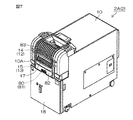
次に、紙幣入出金機2Aに着目して貨幣処理装置2について詳しく説明する。紙幣入出金機2Aは、例えば縦長のボックス状の装置本体10を含む。装置本体10において利用者に臨む前面部10Aの略上半分には、払出口11と、入金口12と、取出口13とが、上側からこの順番に設けられている。例えば100枚といった所定数毎にまとまった状態において帯封された紙幣によって構成された束紙幣が、払出口11から払い出される。入金口12に関連して、装置本体10には、入金口12から装置本体10内へ窪んだ凹状の入金部14が設けられている。入金処理の際に、入金用のバラ紙幣が利用者によって入金口12から入金部14に入金される。取出口13に関連して、装置本体10には、取出口13から装置本体10内へ窪んだ凹状の出金部15が設けられている。出金処理の際に、出金用のバラ紙幣が装置本体10内から出金部15に出金されるので、利用者は、出金部15の紙幣を取出口13から取り出すことができる。   Next, the money handling apparatus 2 will be described in detail with a focus on the banknote depositing and dispensing machine 2A. The bill depositing / dispensing machine 2A includes, for example, a vertically long box-shaped device main body 10. In the apparatus main body 10, a payout port 11, a deposit port 12, and a takeout port 13 are provided in this order from the upper side in a substantially upper half of the front surface portion 10 </ b> A facing the user. For example, a bundle of banknotes composed of banknotes that are bundled in a predetermined state such as 100 sheets is paid out from the payout opening 11. In relation to the deposit port 12, the apparatus main body 10 is provided with a concave deposit portion 14 that is recessed from the deposit port 12 into the apparatus main body 10. During the depositing process, the deposit bills are deposited by the user into the depositing unit 14 from the deposit port 12. In relation to the outlet 13, the apparatus main body 10 is provided with a concave dispensing portion 15 that is recessed from the outlet 13 into the apparatus main body 10. During the withdrawal process, the banknotes for withdrawal are withdrawn from the apparatus main body 10 to the withdrawal unit 15, so that the user can take out the banknotes in the withdrawal unit 15 from the outlet 13.

装置本体10には、モータ等の駆動部(図示せず)の駆動力を受けて払出口11を開閉するシャッタ16と、別の駆動部(図示せず)の駆動力を受けて取出口13を開閉する開閉部の一例としてのシャッタ17とが設けられている。なお、入金口12および入金部14は、常に機外に露出されているが、入金口12を開閉するシャッタを設けても構わない。装置本体10の前面部10Aの略下半分は、扉18を構成している。   The apparatus main body 10 includes a shutter 16 that opens and closes the payout opening 11 by receiving a driving force of a driving unit (not shown) such as a motor, and an outlet 13 that receives a driving force of another driving unit (not shown). A shutter 17 is provided as an example of an opening / closing part that opens and closes the shutter. The deposit port 12 and the deposit unit 14 are always exposed to the outside of the machine, but a shutter for opening and closing the deposit port 12 may be provided. A substantially lower half of the front surface portion 10 </ b> A of the apparatus main body 10 constitutes a door 18.

紙幣入出金機2Aの模式的な縦断面右側面図である図2を参照して、装置本体10内には、バラ紙幣処理部20と、バラ紙幣処理部20の上側に位置する束紙幣処理部21とが設けられている。図2では、バラ紙幣処理部20と束紙幣処理部21との境界線が、1点鎖線によって示されている。バラ紙幣処理部20は、前述した入金部14、出金部15およびシャッタ17の他に、出金リジェクト部24、収納部25、環状搬送路26、取込搬送路27、取出搬送路28、識別部29、反転部30および供給路31を含む。   Referring to FIG. 2, which is a schematic vertical cross-sectional right side view of the banknote depositing / dispensing machine 2 </ b> A, in the apparatus main body 10, a banknote processing unit 20 and a bundled banknote processing located above the bulk banknote processing unit 20. Part 21 is provided. In FIG. 2, a boundary line between the loose banknote processing unit 20 and the bundled banknote processing unit 21 is indicated by a one-dot chain line. In addition to the depositing unit 14, the dispensing unit 15 and the shutter 17, the loose banknote processing unit 20 includes a withdrawal / rejection unit 24, a storage unit 25, an annular conveyance path 26, an intake conveyance path 27, an extraction conveyance path 28, An identification unit 29, a reversing unit 30 and a supply path 31 are included.

前述したシャッタ17は、取出口13を閉鎖して機外から遮断する閉位置(実線のシャッタ17を参照)と、閉位置から上側にずれて取出口13を機外に向けて開放する開位置(破線のシャッタ17を参照)との間において開閉される。出金リジェクト部24は、例えば出金部15の真下に配置された空間である。   The shutter 17 described above has a closed position (see the solid line shutter 17) that closes the outlet 13 and shuts off from outside the machine, and an open position that shifts upward from the closed position and opens the outlet 13 toward the outside of the machine. (See the broken line shutter 17). The withdrawal reject unit 24 is a space arranged, for example, directly below the withdrawal unit 15.

収納部25は、箱状に形成され、複数(ここでは5つ)存在し、前後(図2では左右)に並んで配置されている。これらの収納部25は、扉18とともにスライドすることによって、装置本体10から前側(図2では左側)へ引き出し可能である。5つ並んだ収納部25のうち、前後に隣り合って並んだ3つの収納部25は、バラ紙幣が金種毎に積層状態にて収納される金種別収納部25Aである。別の1つの収納部25は、複数金種のバラ紙幣が混合状態にて一括収納されたり、他の収納部25に収納しきれないオーバーフロー紙幣が収納されたりする一括収納部25Bであり、残りの1つの収納部25は、入金されたバラ紙幣を一時的に収納する一時保留部25Cである。金種別収納部25A、一括収納部25Bおよび一時保留部25Cは、後側(図2では右側)からこの順番にて並んでいる。各収納部25内には、水平な板状のステージ34が配置され、積層状態にて収納されたバラ紙幣は、ステージ34上に配置される。ステージ34は、モータ等の駆動部(図示せず)の駆動力を受けて昇降する。   The storage unit 25 is formed in a box shape, and a plurality (here, five) exist, and are arranged side by side in the front and rear (left and right in FIG. 2). These storage portions 25 can be pulled out from the apparatus main body 10 to the front side (left side in FIG. 2) by sliding together with the door 18. Of the five storage units 25 arranged, three storage units 25 arranged side by side in front and rear are denomination storage units 25A in which loose banknotes are stored in a stacked state for each denomination. Another storage unit 25 is a batch storage unit 25B in which multiple banknotes of different denominations are stored in a mixed state, or overflow banknotes that cannot be stored in the other storage unit 25 are stored. The one storage unit 25 is a temporary storage unit 25C that temporarily stores the received rose banknotes. The denomination storage unit 25A, the batch storage unit 25B, and the temporary storage unit 25C are arranged in this order from the rear side (right side in FIG. 2). A horizontal plate-shaped stage 34 is disposed in each storage unit 25, and loose banknotes stored in a stacked state are disposed on the stage 34. The stage 34 moves up and down in response to a driving force of a driving unit (not shown) such as a motor.

環状搬送路26は、上下に扁平なループ状をなしている。環状搬送路26内のバラ紙幣は、5つの収納部25の上方において、図2における時計回りおよび反時計回りのどちらかに循環するように搬送される。環状搬送路26の下側部分には、分岐路35、36、37、38、39および40の各一端が、環状搬送路26内におけるバラ紙幣の搬送方向に沿って、この順番にて接続されている。分岐路35、36および37の各他端は、3つの金種別収納部25Aのそれぞれに1つずつ上側からつながっている。分岐路38の他端は、一括収納部25Bに上側からつながっている。分岐路39の他端は、一時保留部25Cに上側からつながっている。分岐路40の他端は、出金リジェクト部24につながっている。取込搬送路27は、入金部14に入金されたバラ紙幣を1枚ずつ取り込み、環状搬送路26へ送るための搬送路である。取出搬送路28は、環状搬送路26内のバラ紙幣を出金部15に送るための搬送路である。   The annular conveyance path 26 has a flat loop shape in the vertical direction. The loose banknotes in the annular transport path 26 are transported so as to circulate either in the clockwise direction or the counterclockwise direction in FIG. One end of each of the branch paths 35, 36, 37, 38, 39 and 40 is connected to the lower portion of the annular conveyance path 26 in this order along the conveyance direction of the loose banknotes in the annular conveyance path 26. ing. The other ends of the branch paths 35, 36, and 37 are connected to the three denomination storage units 25A one by one from the upper side. The other end of the branch path 38 is connected to the collective storage unit 25B from above. The other end of the branch path 39 is connected to the temporary storage unit 25C from above. The other end of the branch path 40 is connected to the withdrawal reject unit 24. The take-in conveyance path 27 is a conveyance path for taking the individual banknotes deposited in the depositing unit 14 one by one and sending them to the annular conveyance path 26. The take-out conveyance path 28 is a conveyance path for sending the loose banknotes in the annular conveyance path 26 to the withdrawal unit 15.

識別部29は、環状搬送路26の上側部分の途中領域、詳しくは、環状搬送路26において取込搬送路27に接続された部分と分岐路35に接続された部分との間の領域に配置されている。識別部29は、環状搬送路26において搬送されるバラ紙幣の金種、正損、真偽、表裏等を識別する一般的なセンサである。損傷のあるバラ紙幣や偽のバラ紙幣は、リジェクト紙幣であると識別部29によって識別される。また、識別部29は、バラ紙幣を1枚ずつ識別することによって計数することもできる。   The identification unit 29 is arranged in the middle region of the upper portion of the annular conveyance path 26, specifically, in the region between the portion connected to the intake conveyance path 27 and the portion connected to the branch path 35 in the annular conveyance path 26. Has been. The identification unit 29 is a general sensor that identifies the denomination, correctness, authenticity, front and back, etc., of the loose bills conveyed in the annular conveyance path 26. A damaged rose banknote or a fake rose banknote is identified by the identification unit 29 as being a reject banknote. Moreover, the identification part 29 can also count by identifying a rose banknote one by one.

反転部30は、反転路45と分岐爪46とを含む。反転路45は、略V字に折れ曲がっていて、環状搬送路26から一旦分岐した後に環状搬送路26に合流するように環状搬送路26に対して並列的に接続されている。詳しくは、反転路45は、環状搬送路26において識別部29が設けられた部分と分岐路35に接続された部分との間の領域に対して接続されている。分岐爪46は、反転路45において環状搬送路26から分岐した分岐位置45Aに設けられている。分岐爪46の向きは、ソレノイド等の駆動部(図示せず)の作動に応じて切り換わる。これによって、環状搬送路26内において分岐位置45Aに到達したバラ紙幣を、引き続き環状搬送路26内において搬送したり、反転路45へ搬送したりすることができる。表裏が逆であると識別部29によって識別されたバラ紙幣は、反転路45においてスイッチバックされて表裏が直されてから、環状搬送路26に合流する。供給路31は、環状搬送路26において反転路45が接続された部分と分岐路35に接続された部分との間の領域から分岐して束紙幣処理部21まで延びている。   The reversing unit 30 includes a reversing path 45 and a branching claw 46. The reversing path 45 is bent substantially in a V shape, and is connected in parallel to the annular conveyance path 26 so as to branch from the annular conveyance path 26 and then merge with the annular conveyance path 26. Specifically, the reversing path 45 is connected to a region between the part where the identification unit 29 is provided in the annular conveyance path 26 and the part connected to the branch path 35. The branching claw 46 is provided at a branching position 45 </ b> A branched from the annular conveyance path 26 in the reversing path 45. The direction of the branching claw 46 is switched according to the operation of a drive unit (not shown) such as a solenoid. As a result, the loose bills that have reached the branch position 45 </ b> A in the annular conveyance path 26 can be subsequently conveyed in the annular conveyance path 26 or conveyed to the reversing path 45. The loose bills identified by the identifying unit 29 as being reversed are switched back in the reversing path 45 and the front and back are corrected, and then merged into the annular transport path 26. The supply path 31 branches from the region between the part where the reversing path 45 is connected and the part connected to the branch path 35 in the annular transport path 26 and extends to the bundled bill processing unit 21.

環状搬送路26、取込搬送路27、取出搬送路28、供給路31、分岐路35、36、37、38、39および40ならびに反転路45といった搬送路には、バラ紙幣を搬送するために回転する搬送ローラ(図示せず)や周回移動する搬送ベルト(図示せず)が設けられている。モータ等の駆動部(図示せず)の駆動力を受けて、搬送ローラが回転したり搬送ベルトが周回移動したりする。この搬送ローラは、搬送ローラ47として各収納部25にも設けられ、分岐路35〜39において対応する分岐路からのバラ紙幣を収納部25内に取り込んだり、収納部25内のバラ紙幣を当該分岐路へ送り出したりする。   In order to convey loose banknotes in the conveyance paths such as the annular conveyance path 26, the intake conveyance path 27, the take-out conveyance path 28, the supply path 31, the branch paths 35, 36, 37, 38, 39 and 40, and the reverse path 45 A rotating conveying roller (not shown) and a conveying belt (not shown) that moves around are provided. In response to a driving force of a driving unit (not shown) such as a motor, the conveying roller rotates or the conveying belt rotates. This transport roller is also provided in each storage unit 25 as a transport roller 47, and takes in the banknotes from the corresponding branch path in the branch paths 35 to 39 into the storage unit 25, or receives the banknotes in the storage unit 25 Or send it to a branch.

環状搬送路26と分岐路35〜40のそれぞれとの接続位置には、前述した分岐爪46と同様の分岐爪(図示せず)が設けられており、各分岐爪の向きは、ソレノイド等の駆動部(図示せず)の作動に応じて切り換わる。これによって、環状搬送路26内の紙幣を分岐路35〜40へ搬送することができる。この分岐爪は、取出搬送路28および供給路31のそれぞれと環状搬送路26との接続位置にも設けられていて、この分岐爪の向きが切り換わることによって、環状搬送路26内の紙幣を取出搬送路28や供給路31へ搬送することができる。   A branching claw (not shown) similar to the above-mentioned branching claw 46 is provided at a connection position between the annular conveyance path 26 and each of the branching paths 35 to 40, and the direction of each branching claw is such as a solenoid. It switches according to the operation of the drive unit (not shown). Thereby, the banknote in the annular conveyance path 26 can be conveyed to the branch paths 35-40. This branching claw is also provided at a connection position between each of the take-out conveyance path 28 and the supply path 31 and the annular conveyance path 26. By switching the direction of the branching claw, the banknotes in the annular conveyance path 26 are removed. It can be conveyed to the take-out conveyance path 28 and the supply path 31.

束紙幣処理部21は、前述したシャッタ16の他に、集積部50と、帯封機構51と、縦搬送路52と、リフト53と、横搬送路54と、搬送機構55と、収納部56とを含む。集積部50は、箱状に形成され、複数(ここでは2つ)存在し、上下に並んで配置されている。環状搬送路26から分岐した供給路31は、各集積部50に接続されている。   In addition to the shutter 16 described above, the bundled banknote processing unit 21 includes a stacking unit 50, a bundling mechanism 51, a vertical conveyance path 52, a lift 53, a horizontal conveyance path 54, a conveyance mechanism 55, and a storage unit 56. including. The stacking unit 50 is formed in a box shape, and there are a plurality (two in this case), which are arranged side by side. A supply path 31 branched from the annular transport path 26 is connected to each stacking unit 50.

帯封機構51は、供給路31を経由してバラ紙幣処理部20から集積部50まで搬送されてきたバラ紙幣のまとまりを受け取って帯封することによって束紙幣を作成するためのものであって、帯封機構51の構成として、公知の構成を用いることができる。縦搬送路52は、帯封機構51から上側へ垂直に延びる空間であって、前述した払出口11が縦搬送路52に前側から連通している。リフト53は、水平な板状に形成されて縦搬送路52内に配置されていて、モータ等の駆動部(図示せず)の駆動力を受けて昇降する。   The banding mechanism 51 is for creating a bundle of banknotes by receiving and bundling a bundle of loose banknotes conveyed from the bulk banknote processing unit 20 to the stacking unit 50 via the supply path 31, A known configuration can be used as the configuration of the mechanism 51. The vertical conveyance path 52 is a space extending vertically upward from the banding mechanism 51, and the above-described payout opening 11 communicates with the vertical conveyance path 52 from the front side. The lift 53 is formed in a horizontal plate shape and is disposed in the vertical conveyance path 52, and moves up and down by receiving a driving force of a driving unit (not shown) such as a motor.

横搬送路54は、縦搬送路52の上端から後側へ水平に延びる空間である。搬送機構55は、上下に扁平な無端状のベルト57と、ベルト57を周回移動させるモータ等の駆動部(図示せず)とを含む。ベルト57は、図2における時計回りおよび反時計回りのどちらにも周回移動できる。ベルト57の外周面には、複数の突起57Aが設けられている。複数の突起57Aは、ベルト57の周回移動方向において等間隔にて配置されている。   The horizontal conveyance path 54 is a space that extends horizontally from the upper end of the vertical conveyance path 52 to the rear side. The transport mechanism 55 includes an endless belt 57 that is flattened up and down, and a drive unit (not shown) such as a motor that moves the belt 57 around. The belt 57 can move both clockwise and counterclockwise in FIG. A plurality of protrusions 57 </ b> A are provided on the outer peripheral surface of the belt 57. The plurality of protrusions 57 </ b> A are arranged at equal intervals in the circumferential movement direction of the belt 57.

収納部56は、箱状に形成され、複数(ここでは4つ)存在し、ベルト57の下側において前後に並んで配置されている。各収納部56の上面には、出入口56Aが形成されているとともに、シャッタ58が設けられている。シャッタ58は、モータ等の駆動部(図示せず)の駆動力を受けて出入口56Aを開閉する。各収納部56には、束紙幣が金種毎に積層状態にて収納される。各収納部56内には、水平な板状のステージ59が配置され、積層状態にて収納された束紙幣は、ステージ59上に配置される。ステージ59は、モータ等の駆動部(図示せず)の駆動力を受けて昇降する。これらの収納部56の上面とベルト57とによって上下から挟まれた空間が、横搬送路54である。   The storage portion 56 is formed in a box shape, and there are a plurality (four in this case), which are arranged side by side on the lower side of the belt 57. On the upper surface of each storage portion 56, an entrance 56A is formed and a shutter 58 is provided. The shutter 58 opens and closes the entrance / exit 56 </ b> A in response to a driving force of a driving unit (not shown) such as a motor. In each storage section 56, banknotes are stored in a stacked state for each denomination. A horizontal plate-like stage 59 is disposed in each storage unit 56, and bundled banknotes stored in a stacked state are disposed on the stage 59. The stage 59 moves up and down in response to a driving force of a driving unit (not shown) such as a motor. A space sandwiched from above and below by the upper surface of the storage portion 56 and the belt 57 is a lateral conveyance path 54.

次に、図3のブロック図を参照して、紙幣入出金機2Aの電気的構成について説明する。紙幣入出金機2Aは、制御手段および設定手段の一例としての制御部65と、通信I/F部66と、記憶手段の一例としての記憶部67とを含む。制御部65は、例えばマイクロコンピュータによって構成されている。制御部65には、通信I/F部66および記憶部67のそれぞれと、前述したバラ紙幣処理部20および束紙幣処理部21のそれぞれとが電気的に接続されている。   Next, the electrical configuration of the banknote depositing / dispensing machine 2A will be described with reference to the block diagram of FIG. The bill depositing / dispensing machine 2A includes a control unit 65 as an example of a control unit and a setting unit, a communication I / F unit 66, and a storage unit 67 as an example of a storage unit. The control unit 65 is configured by a microcomputer, for example. The control unit 65 is electrically connected to each of the communication I / F unit 66 and the storage unit 67 and each of the above-described rose banknote processing unit 20 and the bundled banknote processing unit 21.

制御部65は、通信I/F部66を介して、硬貨入出金機2B、操作端末3およびプリンタ4や他の外部機器と通信することができる。そのため、制御部65は、利用者による操作端末3の表示操作部3A(図1参照)の操作を受け付けたり、表示操作部3Aの表示を制御したりする。また、制御部65は、プリンタ4によってレシートを発行する。   The control unit 65 can communicate with the coin depositing / dispensing machine 2B, the operation terminal 3, the printer 4, and other external devices via the communication I / F unit 66. Therefore, the control unit 65 receives an operation of the display operation unit 3A (see FIG. 1) of the operation terminal 3 by the user, or controls the display of the display operation unit 3A. The control unit 65 issues a receipt using the printer 4.

制御部65は、バラ紙幣処理部20における前述した駆動部(図示せず)を制御する。これにより、図2を参照して、制御部65は、各収納部25と、入金部14、出金部15、出金リジェクト部24および集積部50のそれぞれとの間においてバラ紙幣を移動させたり、収納部25同士の間においてバラ紙幣を移動させたり、シャッタ17を開閉させたり、反転部30においてバラ紙幣の表裏を反転させたりする。識別部29による紙幣の識別結果は、制御部65に入力される。制御部65は、識別部29によるバラ紙幣の計数結果に基いて各収納部25におけるバラ紙幣の金種および収納枚数を把握する。   The control part 65 controls the drive part (not shown) in the rose banknote processing part 20 mentioned above. Thereby, referring to FIG. 2, control unit 65 moves the loose bills between each storage unit 25 and each of depositing unit 14, dispensing unit 15, dispensing reject unit 24, and stacking unit 50. Or the bills are moved between the storage units 25, the shutter 17 is opened or closed, and the front and back of the rose bills are reversed in the reversing unit 30. The banknote identification result by the identification unit 29 is input to the control unit 65. The control unit 65 grasps the denomination and the number of stored banknotes in each storage unit 25 based on the counting result of the banknotes by the identifying unit 29.

制御部65は、束紙幣処理部21における前述した駆動部(図示せず)や帯封機構51を制御する。これにより、制御部65は、集積部50に集積されたバラ紙幣を帯封機構51によって束紙幣にしたり、この束紙幣が載せられたリフト53を昇降させることによって束紙幣を縦搬送路52内において垂直移動させたりする。また、制御部65は、リフト53が上限まで昇降した状態において搬送機構55のベルト57を反時計回りに周回移動させることによって、リフト53上の束紙幣をベルト57の突起57Aによって引っ掛けて横搬送路54内において水平移動させる。制御部65は、横搬送路54内の束紙幣が収納先の収納部56の真上まで到達するとベルト57を停止させて、この収納部56のシャッタ58を開く。すると、束紙幣が、収納先の収納部56の上面の出入口56Aから落下して収納部56内に収納される。   The control unit 65 controls the drive unit (not shown) and the bundling mechanism 51 described above in the bundled bill processing unit 21. Thereby, the control part 65 makes the bundled banknote in the vertical conveyance path 52 by making the rose banknote integrated | stacked on the stacking part 50 into a bundle banknote by the banding mechanism 51, or raising / lowering the lift 53 on which this bundle banknote was mounted. Move vertically. Further, the control unit 65 moves the belt 57 of the transport mechanism 55 counterclockwise in a state where the lift 53 is raised and lowered to the upper limit, so that the bundled bills on the lift 53 are hooked by the protrusions 57A of the belt 57 and laterally transported. Move horizontally in the path 54. The control unit 65 stops the belt 57 and opens the shutter 58 of the storage unit 56 when the bundle of bills in the horizontal conveyance path 54 reaches just above the storage unit 56 of the storage destination. Then, the banknotes are dropped from the entrance / exit 56 </ b> A on the upper surface of the storage unit 56 at the storage destination and stored in the storage unit 56.

一方、制御部65は、出金したい束紙幣を収納した収納部56においてステージ59を上昇させてシャッタ58を開き、ベルト57を時計回りに周回移動させる。これにより、収納部56内の束紙幣が、最上位のものから順に、ベルト57の突起57Aによって引っ掛けられて横搬送路54内を水平移動し、縦搬送路52のリフト53に受け渡される。その後、制御部65は、リフト53上の束紙幣が払出口11と上下において一致するまでリフト53を下降させてから、シャッタ16を開く。これにより、利用者は、払出口11から束紙幣を取り出すことができる。   On the other hand, the control unit 65 raises the stage 59 in the storage unit 56 that stores bundled banknotes to be dispensed, opens the shutter 58, and rotates the belt 57 in a clockwise direction. As a result, the banknotes in the storage unit 56 are hooked by the protrusions 57A of the belt 57 in order from the highest one, move horizontally in the horizontal conveyance path 54, and are delivered to the lift 53 of the vertical conveyance path 52. Thereafter, the control unit 65 lowers the lift 53 until the bundled banknotes on the lift 53 coincide with the payout opening 11 in the vertical direction, and then opens the shutter 16. Thereby, the user can take out the banknotes from the payout opening 11.

図3を参照して、記憶部67は、不揮発性メモリやハードディスクドライブといった記憶デバイスによって構成されていて、紙幣入出金機2Aに関する様々な情報を記憶している。特に、記憶部67は、出金部15の取出口13を開閉するシャッタ17の待機位置が開位置(図2の破線参照)および閉位置(図2の実線参照)のどちらであるかを少なくとも記憶している。また、記憶部67は、各収納部25におけるバラ紙幣の金種および収納枚数も記憶している。制御部65は、記憶部67に記憶された情報を参照したり、記憶部67に記憶された情報を書き換えたり、新たな情報を記憶部67に記憶させたりする。   Referring to FIG. 3, the storage unit 67 is configured by a storage device such as a nonvolatile memory or a hard disk drive, and stores various information related to the banknote depositing / dispensing machine 2 </ b> A. In particular, the storage unit 67 determines at least whether the standby position of the shutter 17 that opens and closes the outlet 13 of the dispensing unit 15 is an open position (see the broken line in FIG. 2) or a closed position (see the solid line in FIG. 2). I remember it. The storage unit 67 also stores the denominations and the number of stored banknotes in each storage unit 25. The control unit 65 refers to information stored in the storage unit 67, rewrites information stored in the storage unit 67, and stores new information in the storage unit 67.

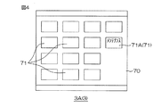
紙幣入出金機2Aでは、シャッタ17の待機位置を開位置および閉位置のどちらかに設定することができる。利用者、厳密には紙幣入出金機2Aを管理する係員が表示操作部3Aに操作することによってログインすると、制御部65は、図4に示すメニュー画面70を表示操作部3Aに表示する。メニュー画面70には、複数のタッチキー71が並んで表示されている。係員が、これらのタッチキー71のうち「メンテナンス」という文字が記されたタッチキー71Aにタッチすると、制御部65は、表示操作部3Aに、図5に示す設定画面72を表示する。設定画面72には、「シャッタの待機位置を選択して下さい」という見出しの下の領域に、「開位置」という文字が記されたタッチキー73と、「閉位置」という文字が記されたタッチキー74とが並んで表示されている。   In the banknote depositing / dispensing machine 2A, the standby position of the shutter 17 can be set to either the open position or the closed position. When the user, who is strictly speaking, a staff member who manages the banknote depositing / dispensing machine 2A logs in by operating the display operation unit 3A, the control unit 65 displays a menu screen 70 shown in FIG. 4 on the display operation unit 3A. On the menu screen 70, a plurality of touch keys 71 are displayed side by side. When the clerk touches the touch key 71A on which the letters “maintenance” are written among these touch keys 71, the control unit 65 displays the setting screen 72 shown in FIG. 5 on the display operation unit 3A. In the setting screen 72, a touch key 73 with characters “open position” and characters “closed position” are written in an area under the heading “Please select a shutter standby position”. Touch keys 74 are displayed side by side.

係員は、シャッタ17の待機位置を開位置に設定したい場合には、タッチキー73にタッチした後に、例えば設定画面72の右下において「確定」という文字が記されたタッチキー75にタッチする。すると、制御部65は、シャッタ17の待機位置が開位置であることを記憶部67に記憶させる。係員は、シャッタ17の待機位置を閉位置に設定したい場合には、タッチキー74および75にタッチする。すると、制御部65は、シャッタ17の待機位置が閉位置であることを記憶部67に記憶させる。なお、係員が、例えば設定画面72の左下において「戻る」という文字が記されたタッチキー76にタッチすれば、制御部65は、表示操作部3Aの表示内容を設定画面72からメニュー画面70(図4参照)に切り替える。   If the attendant wants to set the standby position of the shutter 17 to the open position, after touching the touch key 73, for example, the attendant touches the touch key 75 marked with “fixed” on the lower right of the setting screen 72. Then, the control unit 65 causes the storage unit 67 to store that the standby position of the shutter 17 is the open position. The clerk touches the touch keys 74 and 75 to set the standby position of the shutter 17 to the closed position. Then, the control unit 65 causes the storage unit 67 to store that the standby position of the shutter 17 is the closed position. If the clerk touches, for example, the touch key 76 on which the word “return” is written in the lower left of the setting screen 72, the control unit 65 changes the display content of the display operation unit 3A from the setting screen 72 to the menu screen 70 ( (See FIG. 4).

制御部65は、シャッタ17の実際の待機位置が、記憶部67に記憶された待機位置と一致するようにシャッタ17の開閉を制御する。図6の模式図を参照して、バラ紙幣について収納部56が実行する出金処理および入金処理について、この順番に説明するとともに、シャッタ17の開閉についても説明する。   The control unit 65 controls opening / closing of the shutter 17 so that the actual standby position of the shutter 17 matches the standby position stored in the storage unit 67. With reference to the schematic diagram of FIG. 6, the withdrawal process and the deposit process executed by the storage unit 56 for the loose banknote will be described in this order, and the opening and closing of the shutter 17 will also be described.

制御部65は、利用者による操作端末3の表示操作部3Aの操作によって、出金処理の指示を受け付ける。シャッタ17の待機位置が閉位置(図6における実線のシャッタ17を参照)である場合には、制御部65は、出金処理の開始前も開始時(つまり出金処理の際)もシャッタ17を閉位置に維持するが、シャッタ17の待機位置が開位置(図6における破線のシャッタ17を参照)である場合には、制御部65は、出金処理の開始時にシャッタ17を一旦閉位置まで閉じる。次に、制御部65は、出金対象のバラ紙幣を収納した金種別収納部25Aから必要枚数のバラ紙幣を取り出して、環状搬送路26において反時計回りに搬送し(実線の矢印Y1を参照)、取出搬送路28から出金部15に出金する。なお、制御部65は、環状搬送路26内において搬送されるバラ紙幣のうち、リジェクト紙幣であると識別部29によって識別されたもの(2枚送り紙幣や金種間違い紙幣等も含む)を、分岐路40から出金リジェクト部24にリジェクトする。なお、出金リジェクト部24のリジェクト紙幣は、例えば金融機関の営業時間後に回収される。   The control unit 65 accepts an instruction for a withdrawal process by the operation of the display operation unit 3A of the operation terminal 3 by the user. When the standby position of the shutter 17 is the closed position (see the solid-line shutter 17 in FIG. 6), the control unit 65 is configured to release the shutter 17 both before and at the start of the withdrawal process (that is, during the withdrawal process). However, when the standby position of the shutter 17 is the open position (see the broken line shutter 17 in FIG. 6), the control unit 65 temporarily closes the shutter 17 at the start of the dispensing process. Close until. Next, the control unit 65 takes out the required number of loose banknotes from the denomination storage unit 25A that stores the banknotes to be withdrawn and transports them counterclockwise in the annular transport path 26 (see the solid arrow Y1). ) Withdrawing money from the take-out conveyance path 28 to the withdrawal unit 15. In addition, the control part 65 is what was identified by the identification part 29 as a rejection banknote among the rose banknotes conveyed in the cyclic | annular conveyance path 26 (a 2 sheet | seat banknote, a money type denomination banknote, etc. are included). Reject from the branch path 40 to the withdrawal rejection unit 24. The reject banknote in the withdrawal reject unit 24 is collected after business hours of a financial institution, for example.

シャッタ17の待機位置が閉位置および開位置のいずれである場合にも、出金対象のバラ紙幣が全て出金部15に出金されると、制御部65は、シャッタ17を今までの閉位置から開位置まで開く。そのため、利用者は、開放された取出口13から出金部15のバラ紙幣を取り出すことができる。シャッタ17の待機位置が閉位置である場合には、バラ紙幣が取り出されてから制御部65がシャッタ17を閉位置まで閉じると、出金処理が終了するが、シャッタ17の待機位置が開位置である場合には、バラ紙幣が取り出されると、シャッタ17が開位置にある状態のまま出金処理が終了する。なお、制御部65は、出金部15への出金後にシャッタ17を開いてから所定時間が経過しても出金部15からバラ紙幣が取り出されない場合には、シャッタ17を強制的に閉じて利用者や係員に報知してもよい。この場合、紙幣入出金機2Aには、出金部15におけるバラ紙幣の有無を検知するセンサ(図示せず)とブザーとを含み、制御部65はタイマー機能を有する。   Regardless of whether the standby position of the shutter 17 is the closed position or the open position, when all the banknotes to be dispensed are withdrawn to the withdrawal unit 15, the control unit 65 closes the shutter 17 until now. Open from position to open position. Therefore, the user can take out the loose banknotes of the withdrawal unit 15 from the opened outlet 13. In the case where the standby position of the shutter 17 is the closed position, when the control unit 65 closes the shutter 17 to the closed position after the loose banknotes are taken out, the dispensing process ends, but the standby position of the shutter 17 is the open position. In this case, when the banknotes are taken out, the dispensing process ends with the shutter 17 being in the open position. The controller 65 forcibly moves the shutter 17 if a loose banknote is not taken out from the withdrawal unit 15 even after a predetermined time has elapsed since the shutter 17 was opened after the withdrawal to the withdrawal unit 15. You may close and alert | report to a user or a staff. In this case, the bill depositing / dispensing machine 2A includes a sensor (not shown) for detecting the presence or absence of loose bills in the dispensing unit 15 and a buzzer, and the control unit 65 has a timer function.

シャッタ17の待機位置が開位置および閉位置のいずれである場合にも、出金処理の際には、出金対象のバラ紙幣が全て出金部15に出金されるまではシャッタ17が閉位置まで閉じた状態にあり、出金対象のバラ紙幣が全て出金部15に出金されるとシャッタ17が開位置まで開く。そのため、出金対象のバラ紙幣が全て出金部15に揃っていない途中の段階においてバラ紙幣が取出口13から取り出されることを抑制できる。   Regardless of whether the standby position of the shutter 17 is the open position or the closed position, the shutter 17 is closed until all the loose banknotes to be withdrawn are withdrawn to the withdrawal unit 15 during the withdrawal process. The shutter 17 is opened to the open position when all the banknotes to be withdrawn are withdrawn to the withdrawal unit 15 in the closed state. For this reason, it is possible to prevent the loose banknotes from being taken out from the take-out port 13 in the middle of the stage when all the banknotes to be withdrawn are not aligned with the withdrawal unit 15.

制御部65は、利用者による表示操作部3Aの操作や入金部14への紙幣のセットによって入金処理の指示を受け付ける。制御部65が入金部14への紙幣のセットによって入金処理の指示を受け付ける場合、紙幣入出金機2Aには、入金部14におけるバラ紙幣の有無を検知するセンサ(図示せず)を含む。シャッタ17の待機位置が開位置である場合には、制御部65は、入金処理の開始前も入金処理中もシャッタ17を開位置に維持するが、シャッタ17の待機位置が閉位置である場合には、制御部65は、入金処理の開始時にシャッタ17を開位置まで開き、入金処理の開始後もシャッタ17を開位置に維持する。   The control unit 65 accepts an instruction for deposit processing by an operation of the display operation unit 3 </ b> A by the user or a set of banknotes to the deposit unit 14. When the control unit 65 accepts an instruction for deposit processing by setting a bill to the depositing unit 14, the bill depositing / dispensing machine 2 </ b> A includes a sensor (not shown) that detects the presence or absence of loose bills in the depositing unit 14. When the standby position of the shutter 17 is the open position, the control unit 65 maintains the shutter 17 in the open position before the deposit process is started and during the deposit process, but the standby position of the shutter 17 is the closed position. The controller 65 opens the shutter 17 to the open position at the start of the depositing process, and maintains the shutter 17 in the open position even after the depositing process is started.

次に、制御部65は、利用者によって入金部14に入金されたバラ紙幣を環状搬送路26において時計回りに搬送する(破線の矢印Y2を参照)。その際、制御部65は、環状搬送路26内において搬送されるバラ紙幣のうち、リジェクト紙幣であると識別部29によって識別されたもの(2枚送り紙幣や識別不能紙幣等も含む)を、取出搬送路28から出金部15にリジェクトする。つまり、入金処理の際には、出金部15は、入金部14に入金されたバラ紙幣のうち入金対象外のリジェクト紙幣のリジェクト先、いわゆる入金リジェクト部となる。出金部15のリジェクト紙幣は、開位置のシャッタ17によって開放された取出口13から利用者に随時返却され、入金部14に再セットされたり、再セットされずに別保管されたりする。このように出金部15が入金リジェクト部を兼ねるので、出金部15および入金リジェクト部を別々に設ける場合と比べて、省スペース化や省コスト化を図れる。   Next, the control unit 65 conveys the loose banknotes deposited by the user to the depositing unit 14 in the clockwise direction in the annular conveyance path 26 (see the broken arrow Y2). In that case, the control part 65 is what was identified by the identification part 29 as a rejection banknote among the rose banknotes conveyed in the cyclic | annular conveyance path 26 (a 2 sheet | seat banknote, an unidentifiable banknote, etc. are included). Reject from the take-out conveyance path 28 to the withdrawal unit 15. That is, at the time of deposit processing, the withdrawal unit 15 becomes a reject destination of reject bills that are not subject to deposit among the rose bills deposited in the deposit unit 14, that is, a so-called deposit reject unit. The reject banknote in the withdrawal unit 15 is returned to the user as needed from the outlet 13 opened by the shutter 17 in the open position, and is reset to the deposit unit 14 or stored separately without being reset. Since the withdrawal unit 15 also serves as a deposit rejection unit in this manner, space saving and cost saving can be achieved as compared with the case where the withdrawal unit 15 and the deposit rejection unit are provided separately.

一方、制御部65は、入金部14に入金されて環状搬送路26内において搬送されるバラ紙幣のうち、リジェクト紙幣以外の紙幣、つまり入金対象のバラ紙幣を、一時保留部25Cに収納する。そして、全てのバラ紙幣が入金部14から繰り出されて出金部15または一時保留部25Cに振り分けられ、出金部15のリジェクト紙幣が利用者によって取り出されると、シャッタ17の待機位置が閉位置である場合には制御部65はシャッタ17を閉位置まで閉じ、シャッタ17の待機位置が開位置である場合には制御部65はシャッタ17を開位置のままにする。   On the other hand, the control unit 65 stores, in the temporary storage unit 25C, banknotes other than reject banknotes, that is, rose banknotes to be deposited, among the banknotes deposited in the depositing unit 14 and transported in the annular transport path 26. And when all the rose banknotes are paid out from the depositing unit 14 and distributed to the withdrawal unit 15 or the temporary storage unit 25C, and the reject banknotes of the withdrawal unit 15 are taken out by the user, the standby position of the shutter 17 is closed. In this case, the control unit 65 closes the shutter 17 to the closed position, and when the standby position of the shutter 17 is the open position, the control unit 65 keeps the shutter 17 in the open position.

そして、係員による表示操作部3Aに対する入金処理の承認操作があると、制御部65は、一時保留部25Cのバラ紙幣を、再び識別部29を経由するように環状搬送路26において時計回りに搬送してから、いずれかの金種別収納部25Aまたは一括収納部25Bに金種毎に振り分ける。これにより、入金対象のバラ紙幣は、対応する金種の金種別収納部25Aまたは一括収納部25Bに収納されて、入金処理が終了する。なお、一時保留部25Cのバラ紙幣を金種別収納部25Aや一括収納部25Bに振り分ける前の段階では、利用者による操作端末3の操作等によって今回の入金処理をキャンセルすることができる。入金処理がキャンセルされた場合には、利用者が扉18(図2参照)を開くと、一時保留部25Cが機外に露出されるので、返却処理として、一時保留部25Cに残った紙幣を手作業によって取り出すことができる。返却処理中のシャッタ17は開位置にあってもよい。   When there is a deposit processing approval operation for the display operation unit 3A by the clerk, the control unit 65 conveys the loose banknote of the temporary storage unit 25C clockwise in the annular conveyance path 26 so as to pass through the identification unit 29 again. After that, the money is distributed to any denomination storage unit 25A or collective storage unit 25B for each denomination. As a result, the individual banknotes to be deposited are stored in the corresponding denomination denomination storage unit 25A or batch storage unit 25B, and the deposit process ends. It should be noted that the current deposit process can be canceled by operating the operation terminal 3 by the user or the like before the loose banknotes in the temporary storage unit 25C are distributed to the denomination storage unit 25A or the collective storage unit 25B. When the deposit process is canceled, when the user opens the door 18 (see FIG. 2), the temporary storage unit 25C is exposed to the outside of the apparatus, so that the banknotes remaining in the temporary storage unit 25C are returned as a return process. Can be removed manually. The shutter 17 during the return process may be in the open position.

例えば静粛性が求められる設置環境や、出金処理の実行頻度が高い運用形態では、シャッタ17の待機位置を閉位置に設定しておけば、入金処理のタイミング以外や、出金処理において出金対象の貨幣が全て出金部15に出金されたタイミング以外ではシャッタ17が閉位置にあるので、貨幣処理装置2内部の作動音が取出口13から外部に漏れることを抑制できる。一方、例えば入金処理の実行頻度が高い運用形態、つまり出金部15を入金リジェクト部として使用する頻度が高い運用形態では、シャッタ17の待機位置を開位置に設定しておけば、シャッタ17を開く動作がなくても、入金処理においてリジェクトされる貨幣を取出口13からスムーズに取り出すことができるし、シャッタ17の動作回数の削減によって処理時間の短縮を図ることもできる。つまり、設置環境や運用形態に応じてシャッタ17の待機位置を開位置および閉位置のどちらにも設定できるので、シャッタ17によって開閉される取出口13に関して設置環境や運用形態に適した貨幣処理装置2および貨幣処理システム1を提供できる。   For example, in an installation environment where quietness is required, or in an operation mode in which the withdrawal process is frequently performed, if the standby position of the shutter 17 is set to the closed position, the withdrawal process is performed at a time other than the deposit process or during the withdrawal process. Since the shutter 17 is in the closed position except when all the target money is withdrawn to the withdrawal unit 15, it is possible to suppress the operating sound inside the money handling apparatus 2 from leaking to the outside. On the other hand, for example, in the operation mode in which the deposit processing is frequently executed, that is, in the operation mode in which the withdrawal unit 15 is frequently used as the deposit reject unit, if the standby position of the shutter 17 is set to the open position, the shutter 17 is moved. Even if there is no opening operation, the money rejected in the deposit process can be smoothly taken out from the outlet 13, and the processing time can be shortened by reducing the number of operations of the shutter 17. That is, since the standby position of the shutter 17 can be set to either the open position or the closed position according to the installation environment or operation mode, the money handling apparatus suitable for the installation environment or operation mode with respect to the outlet 13 that is opened and closed by the shutter 17. 2 and the money handling system 1 can be provided.

設置環境や運用形態の変化に応じて、変化後の設置環境や運用形態に適するように、制御部65は、前述した係員による表示操作部3Aでの設定(図5参照)によって、記憶部67におけるシャッタ17の待機位置を開位置および閉位置の一方から他方に切り替えることができる。表示操作部3Aでの設定以外に、所定条件に応じてシャッタ17の待機位置を切り替えてもよい。   In accordance with changes in the installation environment and operation mode, the control unit 65 is configured to be suitable for the changed installation environment and operation mode by the above-described setting in the display operation unit 3A by the staff (see FIG. 5). The standby position of the shutter 17 can be switched from one of the open position and the closed position to the other. In addition to the setting in the display operation unit 3A, the standby position of the shutter 17 may be switched according to a predetermined condition.

例えば、記憶部67が、例えば1ヶ月や1週間といった所定期間における入金処理および出金処理のそれぞれの実行履歴を記憶していて、制御部65は、この実行履歴における入金処理および出金処理のそれぞれの実行頻度に基いて待機位置を切り替えてもよい。この場合、例えば利用者が多い等によって入金処理の実行頻度が高ければ、入金処理においてリジェクト紙幣を取出口13から取り出すための操作性を優先するために待機位置を開位置に切り替えてもよい。一方、出金処理の実行頻度が高ければ、静粛性を優先するために待機位置を閉位置に切り替えてもよい。   For example, the storage unit 67 stores the execution history of each of the deposit process and the withdrawal process in a predetermined period such as one month or one week, for example, and the control unit 65 performs the deposit process and the withdrawal process in the execution history. The standby position may be switched based on each execution frequency. In this case, for example, if the execution frequency of the deposit process is high due to many users or the like, the standby position may be switched to the open position in order to prioritize the operability for taking out the rejected banknote from the outlet 13 in the deposit process. On the other hand, if the withdrawal process is frequently executed, the standby position may be switched to the closed position in order to prioritize quietness.

また、制御部65は、待機位置を切り替えるタイミングを設定してもよく、そのタイミングに待機位置を切り替えてもよい。この場合、制御部65は、カレンダー機能やタイマー機能を有し、シャッタ17の待機位置を時間帯や曜日等のタイミングと対応づけて記憶部67に記憶している。例えば、利用者が少ないタイミングになると、静粛性を重視するために、制御部65は、待機位置を閉位置に設定する。逆に、利用者による入金処理が多いタイミングになると、リジェクト紙幣の発生を想定して、制御部65は、待機位置を開位置に設定する。このように運用形態が変化するタイミングにおいて、変化後の運用形態に適するようにシャッタ17の待機位置を切り替えることができる。   Moreover, the control part 65 may set the timing which switches a standby position, and may switch a standby position at the timing. In this case, the control unit 65 has a calendar function and a timer function, and stores the standby position of the shutter 17 in the storage unit 67 in association with the timing such as the time zone and the day of the week. For example, at a timing when there are few users, the control unit 65 sets the standby position to the closed position in order to emphasize quietness. On the other hand, at the timing when there are many depositing processes by the user, the control unit 65 sets the standby position to the open position, assuming the generation of reject banknotes. Thus, at the timing when the operation mode changes, the standby position of the shutter 17 can be switched so as to be suitable for the changed operation mode.

入金処理および出金処理の実行履歴に基いて待機位置を切り替える場合、および、タイミングに応じて待機位置を切り替える場合のいずれにおいても、待機位置の切り替えは、自動によって行われてもよい。または、例えば紙幣入出金機2Aの起動時等において制御部65が最適な待機位置を操作端末3の表示操作部3Aにて推奨して、係員による承認を得られた場合に、待機位置が切り替えられてもよい。   Whether the standby position is switched based on the execution history of the deposit process and the withdrawal process, or when the standby position is switched according to the timing, the standby position may be switched automatically. Or, for example, when the banknote depositing / dispensing machine 2A is activated, the control unit 65 recommends an optimal standby position in the display operation unit 3A of the operation terminal 3, and the standby position is switched when approval is obtained from an attendant. May be.

なお、制御部65が実行する処理には、前述した入金処理および出金処理以外に、例えば、第1帯封処理、第2帯封処理および精査処理が挙げられる。第1帯封処理として、制御部65は、機外から入金部14に入金されたバラ紙幣を集積部50に直接送り込んで帯封機構51によって束紙幣にして収納部56に収納する。係員による操作端末3での指示があったり、収納部25におけるバラ紙幣の収納枚数が所定数に達したりすると、第2帯封処理として、制御部65は、収納部25のバラ紙幣を帯封機構51によって束紙幣にして収納部56に収納し、当該収納部25に、新たなバラ紙幣を収納するための空きを作る。   Note that the process executed by the control unit 65 includes, for example, a first banding process, a second banding process, and a scrutiny process in addition to the above-described deposit process and withdrawal process. As the first banding process, the control unit 65 directly feeds the banknotes deposited in the depositing unit 14 from the outside of the machine into the stacking unit 50 and stores them in the storage unit 56 as bundled banknotes using the banding mechanism 51. When there is an instruction from the operation terminal 3 by a staff member or when the number of loose banknotes stored in the storage unit 25 reaches a predetermined number, the control unit 65 uses the band banknotes 51 in the storage unit 25 as the second banding process. Thus, a bundle of bills is stored in the storage unit 56, and an empty space for storing new rose bills is created in the storage unit 25.

精査処理として、制御部65は、一時保留部25C以外の各収納部25について、収納部25内の全てのバラ紙幣を一時保留部25Cに移し替えてから元の収納部25に戻し、その際に、識別部29によってバラ紙幣を識別することによって収納部25内のバラ紙幣の金種および収納枚数を確認する。第1帯封処理では、機外から入金部14への入金があるので、出金部15へのバラ紙幣のリジェクトを想定して、シャッタ17の待機位置を開位置に設定することが好ましい。ただし、第2帯封処理および精査処理では、入金部14への入金や出金部15への出金がない状態において、バラ紙幣処理部20や束紙幣処理部21といった装置本体10の内部機構が駆動されるので、静粛性のために、シャッタ17を閉位置にすることが好ましい。   As the scrutiny process, the control unit 65 transfers all loose banknotes in the storage unit 25 to the temporary storage unit 25C and returns them to the original storage unit 25 for each storage unit 25 other than the temporary storage unit 25C. Furthermore, the denomination and the number of stored bills of the rose bills in the storage unit 25 are confirmed by identifying the rose bills by the identification unit 29. In the first banding process, since there is a deposit to the depositing unit 14 from the outside of the machine, it is preferable to set the standby position of the shutter 17 to the open position assuming the rejection of the loose bills to the dispensing unit 15. However, in the second band sealing process and the scrutiny process, the internal mechanisms of the apparatus main body 10 such as the loose banknote processing unit 20 and the bundled banknote processing unit 21 are in a state where there is no depositing to the depositing unit 14 or withdrawal to the dispensing unit 15. Since it is driven, it is preferable to set the shutter 17 in the closed position for quietness.

この発明は、以上の実施形態の内容に限定されるものではなく、請求項に記載の範囲内において種々の変更が可能である。   The present invention is not limited to the contents of the above embodiments, and various modifications can be made within the scope of the claims.

例えば、紙幣入出金機2Aとして、図7に示す変形例が挙げられる。なお、変形例に係る紙幣入出金機2Aの説明に際し、これまでの説明した紙幣入出金機2Aと対応する部品には、同一の符号を付して説明を省略する。変形例に係る紙幣入出金機2Aには、前述した入金リジェクト部が、入金リジェクト部80として、出金部15とは別に設けられ、さらに、入金リジェクト部80からリジェクト紙幣を取り出すための取出口81を開閉するシャッタ82と、入金部14の入金口12を開閉するシャッタ83とが追加されている。変形例に係る紙幣入出金機2Aでは、前述したシャッタ17だけでなく、シャッタ82および83のそれぞれの待機位置が開位置および閉位置のどちらであるかが記憶部67によって記憶されていて、シャッタ17、82および83のそれぞれの待機位置が、記憶部67に記憶された待機位置と一致するように、各シャッタの開閉が制御部65によって制御される。   For example, a modification shown in FIG. In the description of the banknote depositing / dispensing machine 2A according to the modification, parts corresponding to those of the banknote depositing / dispensing machine 2A described so far are denoted by the same reference numerals and description thereof is omitted. In the banknote depositing / dispensing machine 2A according to the modified example, the above-described deposit reject unit is provided as the deposit reject unit 80 separately from the withdrawal unit 15, and an outlet for taking out the reject banknote from the deposit reject unit 80. A shutter 82 that opens and closes 81 and a shutter 83 that opens and closes the deposit port 12 of the depositing unit 14 are added. In the banknote depositing / dispensing machine 2A according to the modified example, the storage unit 67 stores not only the shutter 17 but also the standby positions of the shutters 82 and 83, which is the open position or the closed position. The opening / closing of each shutter is controlled by the control unit 65 so that the standby positions of 17, 82, and 83 coincide with the standby positions stored in the storage unit 67.

また、紙幣入出金機2Aに着目して貨幣処理装置2について説明したが、出金部15およびシャッタ17に相当する構成が硬貨入出金機2B(図1参照)に設けられている場合には、紙幣入出金機2Aにおいて出金部15およびシャッタ17に関する構成は、硬貨入出金機2Bにも適用できる。また、貨幣処理システム1において、紙幣入出金機2Aにおける制御部65や記憶部67(図3参照)は、紙幣入出金機2Aでなく、硬貨入出金機2Bや操作端末3に設けられてもよい。   Moreover, although the money processing apparatus 2 was demonstrated paying attention to 2 A of banknote depositing / withdrawing machines, when the structure corresponded to the withdrawal part 15 and the shutter 17 is provided in the coin depositing / withdrawing machine 2B (refer FIG. 1). In the banknote depositing / dispensing machine 2A, the configuration relating to the dispensing unit 15 and the shutter 17 can also be applied to the coin depositing / dispensing machine 2B. Moreover, in the money handling system 1, even if the control part 65 and the memory | storage part 67 (refer FIG. 3) in the banknote depositing / withdrawing machine 2A are provided not in the banknote depositing / withdrawing machine 2A but in the coin depositing / dispensing machine 2B and the operation terminal 3. Good.

また、貨幣処理システム1は、複数の貨幣処理装置2を統括する管理装置(図示せず)を含んでもよく、この管理装置が、シャッタの待機位置の設定情報を複数の貨幣処理装置2に一括送信し、この設定情報が各貨幣処理装置2の記憶部67に記憶されてもよい。   Further, the money handling system 1 may include a management device (not shown) that controls the plurality of money handling devices 2, and this management device collects the setting information of the standby position of the shutter in the plurality of money handling devices 2. This setting information may be stored in the storage unit 67 of each money handling apparatus 2.

1 貨幣処理システム
2 貨幣処理装置
3 操作端末
13 取出口
14 入金部
15 出金部
17 シャッタ
25 収納部
65 制御部
67 記憶部
DESCRIPTION OF SYMBOLS 1 Money processing system 2 Money processing apparatus 3 Operation terminal 13 Taking out port 14 Depositing part 15 Depositing part 17 Shutter 25 Storage part 65 Control part 67 Storage part

Claims (7)

貨幣が入金される入金部と、
前記入金部に入金された貨幣を収納するための収納部と、
前記収納部の貨幣が出金される出金部であって、前記入金部に貨幣が入金される入金処理の際には、前記入金部に入金された貨幣のうち入金対象外の貨幣のリジェクト先となる出金部と、
前記出金部の貨幣を取り出すための取出口と、
前記取出口を開放する開位置と、前記取出口を閉鎖する閉位置との間において開閉される開閉部と、
前記開閉部の待機位置が前記開位置および前記閉位置のどちらであるかを記憶する記憶手段と、
前記開閉部の待機位置が、前記記憶手段に記憶された待機位置と一致するように前記開閉部の開閉を制御する制御手段とを含む、貨幣処理装置。
A depositing part in which money is deposited;
A storage unit for storing money deposited in the deposit unit;
A withdrawal unit for withdrawing money from the storage unit, and when depositing money into the depositing unit, rejecting money that is not to be deposited out of the money deposited in the depositing unit. Withdrawal department ahead,
An outlet for taking out the money of the withdrawal unit;
An opening / closing part that is opened and closed between an open position that opens the outlet and a closed position that closes the outlet;
Storage means for storing whether the standby position of the opening and closing unit is the open position or the closed position;
A money handling apparatus, comprising: control means for controlling opening / closing of the opening / closing section so that a standby position of the opening / closing section matches a standby position stored in the storage means.
前記待機位置が前記開位置である場合には、前記制御手段は、前記入金処理の際に前記開閉部を前記開位置に維持し、前記出金部に貨幣が出金される出金処理の際に、前記開閉部を前記閉位置まで閉じて、出金対象の貨幣が全て前記出金部に出金されると前記開閉部を前記開位置まで開く、請求項1に記載の貨幣処理装置。   When the standby position is the open position, the control means maintains the opening / closing part in the open position during the deposit process, and performs a withdrawal process in which money is dispensed to the withdrawal part. The money processing apparatus according to claim 1, wherein the opening / closing part is closed to the closed position, and the opening / closing part is opened to the open position when all of the money to be dispensed is withdrawn to the dispensing part. . 前記待機位置が前記閉位置である場合には、前記制御手段は、前記入金処理の際に前記開閉部を前記開位置まで開き、前記出金部に貨幣が出金される出金処理の際に、前記開閉部を前記閉位置に維持し、出金対象の貨幣が全て前記出金部に出金されると前記開閉部を前記開位置まで開く、請求項1に記載の貨幣処理装置。   When the standby position is the closed position, the control means opens the opening / closing part to the open position during the depositing process, and performs a dispensing process in which money is dispensed to the dispensing part. The money processing apparatus according to claim 1, wherein the opening / closing part is maintained at the closed position, and the opening / closing part is opened to the open position when all of the money to be dispensed is dispensed to the dispensing part. 前記制御手段は、前記待機位置を前記開位置および前記閉位置の一方から他方に切り替える、請求項2または3に記載の貨幣処理装置。   4. The money handling apparatus according to claim 2, wherein the control unit switches the standby position from one of the open position and the closed position to the other. 前記記憶手段は、所定期間における前記入金処理および前記出金処理のそれぞれの実行履歴を記憶し、
前記制御手段は、前記実行履歴における前記入金処理および前記出金処理のそれぞれの実行頻度に基いて前記待機位置を切り替える、請求項4に記載の貨幣処理装置。
The storage means stores respective execution histories of the deposit process and the withdrawal process in a predetermined period,
5. The money handling apparatus according to claim 4, wherein the control unit switches the standby position based on each execution frequency of the deposit process and the withdrawal process in the execution history.
前記待機位置を切り替えるタイミングを設定する設定手段を含み、
前記制御手段は、前記設定手段によって設定されたタイミングに前記待機位置を切り替える、請求項4に記載の貨幣処理装置。
Setting means for setting a timing for switching the standby position;
The money handling apparatus according to claim 4, wherein the control unit switches the standby position at a timing set by the setting unit.
貨幣処理装置と、前記貨幣処理装置と通信可能な操作端末とを含む貨幣処理システムであって、
貨幣が入金される入金部と、
前記入金部に入金された貨幣を収納するための収納部と、
前記収納部の貨幣が出金される出金部であって、前記入金部に貨幣が入金される入金処理の際には、前記入金部に入金された貨幣のうち入金対象外の貨幣のリジェクト先となる出金部と、
前記出金部の貨幣を取り出すための取出口と、
前記取出口を開放する開位置と、前記取出口を閉鎖する閉位置との間において開閉される開閉部と、
前記開閉部の待機位置が前記開位置および前記閉位置のどちらであるかを記憶する記憶手段と、
前記開閉部の待機位置が、前記記憶手段に記憶された待機位置と一致するように前記開閉部の開閉を制御する制御手段とを含む、貨幣処理システム。
A money handling system including a money handling device and an operation terminal capable of communicating with the money handling device,
A depositing part in which money is deposited;
A storage unit for storing money deposited in the deposit unit;
A withdrawal unit for withdrawing money from the storage unit, and when depositing money into the depositing unit, rejecting money that is not to be deposited out of the money deposited in the depositing unit. Withdrawal department ahead,
An outlet for taking out the money of the withdrawal unit;
An opening / closing part that is opened and closed between an open position that opens the outlet and a closed position that closes the outlet;
Storage means for storing whether the standby position of the opening and closing unit is the open position or the closed position;
A money handling system comprising: control means for controlling opening / closing of the opening / closing section so that a standby position of the opening / closing section matches a standby position stored in the storage means.
JP2016136902A 2016-07-11 2016-07-11 Money handling equipment and money handling system Active JP6666210B2 (en)

Priority Applications (2)

Application Number Priority Date Filing Date Title
JP2016136902A JP6666210B2 (en) 2016-07-11 2016-07-11 Money handling equipment and money handling system
JP2020027505A JP6982112B2 (en) 2016-07-11 2020-02-20 Money processing equipment and money processing system

Applications Claiming Priority (1)

Application Number Priority Date Filing Date Title
JP2016136902A JP6666210B2 (en) 2016-07-11 2016-07-11 Money handling equipment and money handling system

Related Child Applications (1)

Application Number Title Priority Date Filing Date
JP2020027505A Division JP6982112B2 (en) 2016-07-11 2020-02-20 Money processing equipment and money processing system

Publications (2)

Publication Number Publication Date
JP2018010355A true JP2018010355A (en) 2018-01-18
JP6666210B2 JP6666210B2 (en) 2020-03-13

Family

ID=60994346

Family Applications (1)

Application Number Title Priority Date Filing Date
JP2016136902A Active JP6666210B2 (en) 2016-07-11 2016-07-11 Money handling equipment and money handling system

Country Status (1)

Country Link
JP (1) JP6666210B2 (en)

Cited By (1)

* Cited by examiner, † Cited by third party
Publication number Priority date Publication date Assignee Title
JP2019185200A (en) * 2018-04-04 2019-10-24 日立オムロンターミナルソリューションズ株式会社 Banknote handling device

Citations (4)

* Cited by examiner, † Cited by third party
Publication number Priority date Publication date Assignee Title
JPS5175295U (en) * 1974-12-11 1976-06-14
JP2005157425A (en) * 2003-11-20 2005-06-16 Fujitsu Ltd Automatic transaction device, automatic transaction control method, and control program therefor
JP2008165469A (en) * 2006-12-28 2008-07-17 Oki Electric Ind Co Ltd Automatic transaction apparatus
JP2014241096A (en) * 2013-06-12 2014-12-25 グローリー株式会社 Valuable medium processor and valuable medium processing method

Patent Citations (4)

* Cited by examiner, † Cited by third party
Publication number Priority date Publication date Assignee Title
JPS5175295U (en) * 1974-12-11 1976-06-14
JP2005157425A (en) * 2003-11-20 2005-06-16 Fujitsu Ltd Automatic transaction device, automatic transaction control method, and control program therefor
JP2008165469A (en) * 2006-12-28 2008-07-17 Oki Electric Ind Co Ltd Automatic transaction apparatus
JP2014241096A (en) * 2013-06-12 2014-12-25 グローリー株式会社 Valuable medium processor and valuable medium processing method

Cited By (2)

* Cited by examiner, † Cited by third party
Publication number Priority date Publication date Assignee Title
JP2019185200A (en) * 2018-04-04 2019-10-24 日立オムロンターミナルソリューションズ株式会社 Banknote handling device
JP7132737B2 (en) 2018-04-04 2022-09-07 日立チャネルソリューションズ株式会社 Banknote handling device

Also Published As

Publication number Publication date
JP6666210B2 (en) 2020-03-13

Similar Documents

Publication Publication Date Title
CN108140274B (en) ATM with escrow device
EP3483847B1 (en) Money processing device and money processing system
RU2573365C2 (en) Banknote handling device
JP5503982B2 (en) Valuable medium processing apparatus and valuable medium processing method
US20090118861A1 (en) Paper money receiving/dispensing mechanism and automatic teller machine
JP2003346221A (en) Bill handling device and atm
JP4117630B2 (en) Banknote handling equipment
JP4051388B2 (en) Banknote deposit and withdrawal machine
JP2000172903A (en) Paper money receipt/payment machine
JP4887554B2 (en) Automatic transaction equipment
JPH11224362A (en) Paper money handling device
WO2017126410A1 (en) Banknote handling device
JP2018010355A (en) Money processor and money processing system
JP6910212B2 (en) Money processing equipment and money processing system
JP2002236961A (en) Bill teller machine
JP6982112B2 (en) Money processing equipment and money processing system
JP2018005485A (en) Bill processor, bill processing system and bill processing method
JP2012238247A (en) Automatic teller machine
JP2016177570A (en) Bill processor and bill processing method
US20220335768A1 (en) Banknote deposit-withdrawal system and architecture
JP7242416B2 (en) Banknote processing equipment
JP7132737B2 (en) Banknote handling device
JP2019049791A (en) Currency processing device
JP7296858B2 (en) Money handling device and money handling system
CN108510642B (en) Automatic cash transaction device

Legal Events

Date Code Title Description
A621 Written request for application examination

Free format text: JAPANESE INTERMEDIATE CODE: A621

Effective date: 20190408

A977 Report on retrieval

Free format text: JAPANESE INTERMEDIATE CODE: A971007

Effective date: 20200115

TRDD Decision of grant or rejection written
A01 Written decision to grant a patent or to grant a registration (utility model)

Free format text: JAPANESE INTERMEDIATE CODE: A01

Effective date: 20200130

A61 First payment of annual fees (during grant procedure)

Free format text: JAPANESE INTERMEDIATE CODE: A61

Effective date: 20200220

R150 Certificate of patent or registration of utility model

Ref document number: 6666210

Country of ref document: JP

Free format text: JAPANESE INTERMEDIATE CODE: R150