JP2018009890A - Fusion reactor blanket subunit, its manufacturing method, and fusion reactor blanket - Google Patents
Fusion reactor blanket subunit, its manufacturing method, and fusion reactor blanket Download PDFInfo
- Publication number
- JP2018009890A JP2018009890A JP2016139327A JP2016139327A JP2018009890A JP 2018009890 A JP2018009890 A JP 2018009890A JP 2016139327 A JP2016139327 A JP 2016139327A JP 2016139327 A JP2016139327 A JP 2016139327A JP 2018009890 A JP2018009890 A JP 2018009890A
- Authority
- JP
- Japan
- Prior art keywords
- subunit
- lithium
- housing
- fusion reactor
- wall
- Prior art date
- Legal status (The legal status is an assumption and is not a legal conclusion. Google has not performed a legal analysis and makes no representation as to the accuracy of the status listed.)
- Granted
Links
Images


Classifications
-
- Y—GENERAL TAGGING OF NEW TECHNOLOGICAL DEVELOPMENTS; GENERAL TAGGING OF CROSS-SECTIONAL TECHNOLOGIES SPANNING OVER SEVERAL SECTIONS OF THE IPC; TECHNICAL SUBJECTS COVERED BY FORMER USPC CROSS-REFERENCE ART COLLECTIONS [XRACs] AND DIGESTS
- Y02—TECHNOLOGIES OR APPLICATIONS FOR MITIGATION OR ADAPTATION AGAINST CLIMATE CHANGE
- Y02E—REDUCTION OF GREENHOUSE GAS [GHG] EMISSIONS, RELATED TO ENERGY GENERATION, TRANSMISSION OR DISTRIBUTION
- Y02E30/00—Energy generation of nuclear origin
- Y02E30/10—Nuclear fusion reactors
Landscapes
- Physical Or Chemical Processes And Apparatus (AREA)
- Measurement Of Radiation (AREA)
Abstract
【課題】十分に大きなトリチウム増殖比を安定して実現できる核融合炉ブランケットを提供する。【解決手段】核融合炉ブランケットサブユニットは、リチウムまたはリチウム化合物を含むリチウム含有体25と、リチウム含有体25を収納して密閉するベリリウム製の稠密収納体26を備えた増倍材ブロックと、増倍材ブロックを収納して密閉するサブユニット筐体と、を有する。サブユニット筐体の外側と内側とを連絡してサブユニット筐体内を冷却する冷却水が流れる冷却水流路が形成されている。サブユニット筐体の外側と内側とを連絡してサブユニット筐体内で生じたトリチウムをサブユニット筐体外に搬送するガス流路が形成されている。【選択図】図4A fusion reactor blanket capable of stably realizing a sufficiently large tritium breeding ratio is provided. A fusion reactor blanket subunit includes a lithium-containing body 25 containing lithium or a lithium compound, and a multiplier block provided with a dense storage body 26 made of beryllium that houses and seals the lithium-containing body 25. And a subunit housing that houses and seals the multiplier block. A cooling water flow path is formed through which cooling water that cools the inside of the subunit housing is communicated with the outside and inside of the subunit housing. A gas flow path is formed in which the tritium generated in the subunit housing is conveyed outside the subunit housing by connecting the outside and the inside of the subunit housing. [Selection] Figure 4
Description
本発明の実施形態は、核融合炉ブランケットサブユニットおよびその製造方法ならびに核融合炉ブランケットに関する。 Embodiments of the present invention relate to a fusion reactor blanket subunit, a method for manufacturing the same, and a fusion reactor blanket.
核融合炉ブランケット(以下、単に「ブランケット」ともいう。)は、核融合炉からエネルギーを取り出すためのキーコンポーネントである。 A fusion reactor blanket (hereinafter also simply referred to as a “blanket”) is a key component for extracting energy from a fusion reactor.
核融合炉ブランケットシステムは、中性子照射を受け、内部で中性子を増倍し、トリチウム生産を行うためのものであって、筐体構造とその後方のトリチウム回収系などからなる複合システムである。 The fusion reactor blanket system is a composite system that receives neutron irradiation, multiplies neutrons inside, and produces tritium, and includes a housing structure and a tritium recovery system behind the case structure.
核融合炉では燃料としてトリチウムを用いるが、トリチウムは天然には存在しないため、核融合炉内で自己生成して燃料サイクルを成立させる必要がある。ブランケットシステムにおけるトリチウムの生産性(TBR:トリチウム増殖比)およびその連続稼動を可能にするため、トリチウム回収や炉心への再投入まで含めたプラントシステムでの評価値としてのTBRが1.05よりも大きいこと、および、サブユニット単独での評価でTBRが1.25よりも大きいこと、が必要と試算している。 Although tritium is used as a fuel in a nuclear fusion reactor, since tritium does not exist in nature, it must be self-generated in the nuclear fusion reactor to establish a fuel cycle. In order to enable tritium productivity (TBR: tritium breeding ratio) and its continuous operation in the blanket system, TBR as an evaluation value in the plant system including tritium recovery and reintroduction into the core is more than 1.05 It is estimated that it is necessary and that TBR is larger than 1.25 in the evaluation of the subunit alone.
一方で、リチウムは極めて化学活性な金属であり、高温で水に触れると激しい発熱反応をすることから、従来、化学的に安定なリチウム化合物が使われてきた。しかしこれらは、サブユニット内のリチウム量を低減するとともに、中性子を吸収・消費し、トリチウム増殖の大きな弊害となっている。 On the other hand, lithium is an extremely chemically active metal and reacts violently with heat at high temperatures, so that chemically stable lithium compounds have been used in the past. However, these reduce the amount of lithium in the subunit and absorb and consume neutrons, which is a serious detrimental effect on tritium growth.
本発明の実施形態はこのような課題を解決するためになされたものであり、十分に大きなトリチウム増殖比を安定して実現できる核融合炉ブランケットおよびそのためのブランケットサブユニットを提供することを目的とする。 Embodiments of the present invention have been made to solve such problems, and an object thereof is to provide a fusion reactor blanket capable of stably realizing a sufficiently large tritium breeding ratio and a blanket subunit therefor. To do.
本発明の一つの実施形態に係る核融合炉ブランケットサブユニットは、リチウムまたはリチウム化合物を含むリチウム含有体と、前記リチウム含有体を収納して密閉するベリリウム製の稠密収納体を備えた増倍材ブロックと、前記増倍材ブロックを収納して密閉するサブユニット筐体と、を有し、前記サブユニット筐体の外側と内側とを連絡して前記サブユニット筐体内を冷却する冷却水が流れる冷却水流路が形成され、前記サブユニット筐体の外側と内側とを連絡して前記サブユニット筐体内で生じたトリチウムを前記サブユニット筐体外に搬送するガス流路が形成されていること、を特徴とする。 A nuclear fusion reactor blanket subunit according to one embodiment of the present invention includes a lithium-containing body containing lithium or a lithium compound, and a beryllium dense housing body that houses and seals the lithium-containing body. A block and a subunit housing that houses and seals the multiplier block, and cooling water that cools the inside of the subunit housing flows between the outside and the inside of the subunit housing. A cooling water flow path is formed, and a gas flow path is formed that communicates the outside and inside of the subunit housing to convey tritium generated in the subunit housing to the outside of the subunit housing. Features.
本発明の他の一つの実施形態に係る核融合炉ブランケットサブユニットは、リチウム化合物を含むリチウム含有体と、前記リチウム含有体を収納して密閉するベリリウム製の粗密収納体を備えた増倍材ブロックと、前記増倍材ブロックを収納して密閉するサブユニット筐体と、を有し、前記サブユニット筐体の外側と内側とを連絡して前記サブユニット筐体内を冷却する冷却水が流れる冷却水流路が形成され、前記サブユニット筐体の外側と内側とを連絡して前記サブユニット筐体内で生じたトリチウムを前記サブユニット筐体外に搬送するガス流路が形成されていること、を特徴とする。 A nuclear fusion reactor blanket subunit according to another embodiment of the present invention includes a lithium-containing body containing a lithium compound, and a multiplying material provided with a coarse and dense container made of beryllium that houses and seals the lithium-containing body. A block and a subunit housing that houses and seals the multiplier block, and cooling water that cools the inside of the subunit housing flows between the outside and the inside of the subunit housing. A cooling water flow path is formed, and a gas flow path is formed that communicates the outside and inside of the subunit housing to convey tritium generated in the subunit housing to the outside of the subunit housing. Features.
本発明の一つの実施形態に係る核融合炉ブランケットは、プラズマを閉じ込める真空容器の内面に沿って配列された前記核融合炉ブランケットサブユニットの複数個、を備えることを特徴とする。 A fusion reactor blanket according to an embodiment of the present invention includes a plurality of the fusion reactor blanket subunits arranged along an inner surface of a vacuum vessel for confining plasma.
本発明の一つの実施形態に係る核融合炉ブランケットサブユニット製造方法は、多孔質ベリリウム体にリチウムまたはリチウム化合物を含浸させてリチウムまたはリチウム化合物を含むリチウム含有体を作成するリチウム含有体作成工程と、ベリリウム製の稠密収納体内に前記リチウム含有体を収納して密閉してリチウム−ベリリウムペレットを作成するペレット作成工程と、前記ペレット作成工程の後にサブユニット筐体内に前記リチウム−ベリリウムペレットを収納して密閉するサブユニット筐体収納工程と、を有することを特徴とする。 A fusion reactor blanket subunit manufacturing method according to an embodiment of the present invention includes a lithium-containing body creation step of creating a lithium-containing body containing lithium or a lithium compound by impregnating a porous beryllium body with lithium or a lithium compound; A pellet forming step in which the lithium-containing body is stored in a dense beryllium container and sealed to form a lithium-beryllium pellet; and the lithium-beryllium pellet is stored in a subunit housing after the pellet forming step. And a sub-unit housing housing step for hermetically sealing.
本発明の実施形態によれば、核融合炉ブランケットにおいて、十分に大きなトリチウム増殖比を安定して実現できる。 According to the embodiment of the present invention, a sufficiently large tritium breeding ratio can be stably realized in a fusion reactor blanket.
ブランケットの開発・設計・製作に必要な3つの機能を以下に示す。
(1)核融合反応中性子を受けて、運動エネルギーを熱として回収する。
D+T→ n(14.1MeV)+He(3.5MeV)
(2)反応中性子を増倍する。
Be−9+n → 2n+2He−2.5MeV
(3)トリチウムを増殖し、回収して燃料として再利用する。
Li−6+n → T+He+4.8MeV
Three functions necessary for blanket development, design, and production are shown below.
(1) Fusion reaction Receiving neutrons and recovering kinetic energy as heat.
D + T → n (14.1 MeV) + He (3.5 MeV)
(2) Multiply reactive neutrons.
Be-9 + n → 2n + 2He-2.5MeV
(3) Tritium is propagated, recovered and reused as fuel.
Li-6 + n → T + He + 4.8 MeV
以下、図面を参照しながら、本発明の実施形態に係る核融合炉ブランケットについて説明する。ここで、互いに同一または類似の部分には共通の符号を付して、重複説明は省略する。 Hereinafter, a fusion reactor blanket according to an embodiment of the present invention will be described with reference to the drawings. Here, the same or similar parts are denoted by common reference numerals, and redundant description is omitted.
[第1の実施形態]
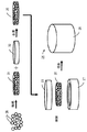
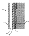
図1は、第1の実施形態に係る核融合炉ブランケットサブユニットの模式的縦断面図である。図2は、第1の実施形態に係る複数の核融合炉ブランケットサブユニットを配置した状況を示す核融合炉の模式的な要部縦断面図である。図3は、第1の実施形態に係る核融合炉ブランケットサブユニットを構成する一つの増倍材ブロックの縦断面図である。図4は、第1の実施形態に係る増倍材ブロックを構成する一つのペレットの縦断面図である。図5は、図4のペレットの製造プロセスを示す説明図である。図6は、図3の増倍材ブロックの製造プロセスを示す説明図である。図7は、第1の実施形態に係る複数の核融合炉ブランケットサブユニットにおけるサブユニット筐体の壁面近傍を示す要部拡大縦断面図である。
[First Embodiment]
FIG. 1 is a schematic longitudinal sectional view of a nuclear fusion reactor blanket subunit according to the first embodiment. FIG. 2 is a schematic longitudinal sectional view of a main part of a nuclear fusion reactor showing a state in which a plurality of nuclear fusion reactor blanket subunits according to the first embodiment are arranged. FIG. 3 is a longitudinal sectional view of one multiplier block constituting the nuclear fusion reactor blanket subunit according to the first embodiment. FIG. 4 is a longitudinal sectional view of one pellet constituting the multiplier block according to the first embodiment. FIG. 5 is an explanatory view showing a manufacturing process of the pellet of FIG. FIG. 6 is an explanatory view showing a manufacturing process of the multiplier block of FIG. FIG. 7 is an enlarged vertical cross-sectional view of the main part showing the vicinity of the wall surface of the subunit housing in the plurality of fusion reactor blanket subunits according to the first embodiment.
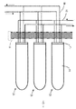
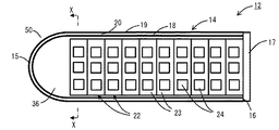
図2に示すように、核融合炉の真空容器11の内面に沿って多数の核融合炉ブランケットサブユニット(以下、単に「サブユニット」とも呼ぶ。)12が配列されている。核融合炉の運転により、真空容器11内に核融合プラズマ13が形成される。
As shown in FIG. 2, a large number of fusion reactor blanket subunits (hereinafter also simply referred to as “subunits”) 12 are arranged along the inner surface of the
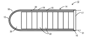
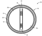
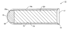
図1に示すように、各サブユニット12は、真空容器11の内面にほぼ垂直な軸方向に延びる円筒形のサブユニット筐体14に覆われている。サブユニット筐体14の核融合プラズマ13に対向する端部(第1の端部)15には半球状部50が形成されている。サブユニット筐体14の第1の端部15の反対側の第2の端部16は、円板状の底板17によって密閉されている。
As shown in FIG. 1, each
サブユニット筐体14は、内壁18とその外側の外壁19とによって二重壁構造をなしており、内壁18と外壁19との間に冷却水流路20が形成されている。内壁18および外壁19は、たとえば、フェライト系ステンレス鋼製である。冷却水流路20は、底板17を貫通する冷却水配管21に接続され、この冷却水配管21は、サブユニット筐体14の外側の熱交換器(図示せず)と接続されている。
The
サブユニット筐体14内には、複数の円板状の増倍材ブロック22が積層されている。
A plurality of disk-like multiplier blocks 22 are stacked in the
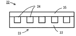
図3に示すように、各増倍材ブロック22は、粗密収納体23と、粗密収納体23内に収納されて密閉された複数のリチウム‐ベリリウムペレット(以下、単に「ペレット」とも呼ぶ)24とを有する。粗密収納体23は、たとえば密度(充填率)80〜90%程度の粗密ベリリウム製である。各粗密収納体23内で、複数のペレット24が互いに間隔をあけて、軸に垂直な一つの平面内で分散して配置されている。
As shown in FIG. 3, each
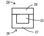
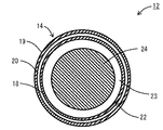
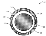
図4に示すように、各リチウム‐ベリリウムペレット24は、円板状のリチウム含有体25と、リチウム含有体25を収納して密閉する稠密収納体26とを有する。リチウム含有体25は、円板状のベリリウム多孔質体31(図5参照)にリチウムを含浸させて円板状としたものである。ベリリウム多孔質体31の密度は、粗密収納体23の密度よりも低く、たとえば65〜80%程度である。稠密収納体26は粗密収納体23よりも密度が高く、たとえば、密度90〜100%の稠密ベリリウム製である。
As shown in FIG. 4, each lithium-
ここで、リチウム−ベリリウムペレット24の製造プロセスを、図5に沿って説明する。図5において、プロセスの順序を黒い太矢印で示す。以下のプロセス説明図でも同様とする。
Here, the manufacturing process of the lithium-
初めに、多数のベリリウム粒30を焼結して円板状のベリリウム多孔質体31を生成する。ベリリウム粒30は、たとえば直径1mm程度である。つぎに、円板状のリチウム板32とベリリウム多孔質体31とを重ねて加熱して、リチウム板32を溶融させて、ベリリウム多孔質体31にリチウムを含浸させ、円板状のリチウム含有体25を生成する。含浸は、たとえば150〜200℃程度で行うことができる。リチウムは濡れ性が良いため、容易に含浸する。つぎに、リチウム含有体25を円筒状の稠密収納容器本体27内に収納する。
First, a large number of
つぎに、円板状の稠密収納容器蓋28(図3)を被せて密閉し、成型して、リチウム−ベリリウムペレット24(図4)が完成する。稠密収納容器本体27と稠密収納容器蓋28とで稠密収納体26が構成される。密閉は、真空中で行う。稠密収納容器蓋28を被せて密閉する際に、稠密収納体26内の大気(おもに酸素と窒素)が残留するが、密閉する際に加えられる熱によりリチウムが溶融し、そのときに稠密収納体26内の大気を取り込むため、稠密収納体26内のガスの活性が低くなる。
Next, a disk-shaped dense storage container lid 28 (FIG. 3) is placed, sealed, and molded to complete the lithium-beryllium pellet 24 (FIG. 4). The dense
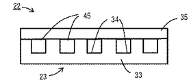
つぎに、増倍材ブロック22の製造プロセスを、図6に沿って説明する。粗密収納体23の一部を構成する円柱状の粗密収納容器本体33の上面に、ペレット24を1個ずつ収容する複数の穴(くぼみ)34を形成しておく。これらの穴34は互いに間隔をあけて平面的に分散して配置する。また、各穴34の形状および大きさはペレット24の形状および大きさに合わせ、なるべく隙間があかないような設計とする。つぎに、これらの穴34にペレット24を挿入する。つぎに、粗密収納容器本体33の上面に円板状の粗密収納容器蓋35を被せて、すべてのペレット24含めて粗密収納容器本体33の上面を覆い、密閉する。このとき、粗密収納容器本体33と粗密収納容器蓋35とによって粗密収納体23が構成される。
Next, the manufacturing process of the
なお、粗密収納容器本体33および粗密収納容器蓋35は、ベリリウム粉末(図示せず)から、粉末冶金で生成することができる。その際に、粉末焼成時の圧力を調整することにより、焼成後の密度(充填率)を制御することができる。
The coarse / dense
図1に示すように、サブユニット筐体14の半球状部50内には、多数のベリリウム粒36が充填されている。さらに、図7に示すように、サブユニット筐体14の内壁18の内側の増倍材ブロック22との間の環状の空隙に多数のベリリウム粒37が充填されている。ベリリウム粒36とベリリウム粒37とは同様のものでよい。ベリリウムは熱伝導率が高いことから、ベリリウム粒36、37の存在によって、増倍材ブロック22内の熱を内壁18に伝え、冷却水流路20内を流れる冷却水に放熱することができる。
As shown in FIG. 1, a large number of
底板17を貫通してガス配管40(図2)が取り付けられている。ガス配管40はサブユニット筐体14の外側でトリチウム回収機構(図示せず)に接続されている。ガス配管40にはヘリウムなどのスイープガスが流され、サブユニット筐体14内で発生したトリチウムがスイープガスとともにガス配管40を通ってトリチウム回収機構に送られて、トリチウムが回収される。
A gas pipe 40 (FIG. 2) is attached through the
この実施形態によれば、リチウムをベリリウム多孔質体31に含浸させて、リチウム密度を高め、トリチウム増殖率を高めることができる。また、ベリリウム製の稠密収納体26およびベリリウム製の粗密収納体23を用いることにより、万一、冷却水がサブユニット筐体14内に漏洩した場合であっても、リチウムと水とが接触することによって生じる化学反応を防止することができる。それと同時に、リチウム含有体25を確実に冷却することができる。
According to this embodiment, the beryllium
リチウム−ベリリウムペレット24の中で発生したトリチウムは、ベリリウム製の稠密収納体26を透過し、さらに、ベリリウム製の粗密収納体23を透過して、ガス配管40から回収される。
The tritium generated in the lithium-
ベリリウム製の稠密収納体26とベリリウム製の粗密収納体23とは、密度が相違するものの、同じ材質であるから、温度変化に伴う膨張・収縮の差が生じず、構造の健全性を保つことができる。
The beryllium
サブユニット筐体14内での冷却水の漏洩を想定すると、増倍材ブロック22が急激に冷却されることが考えられる。そのような場合、ベリリウムの温度が400℃以下に低下すると、ベリリウムの延性が急激に低下するので、一般に、熱衝撃による破損(割れ)が懸念される。しかし、この実施形態では、粗密ベリリウム製の粗密収納体23を用いることにより、割れが生じにくく、また、かりに局所的な割れが発生しても、その割れが伝搬せず、形状と機能を維持することができる。しかも、優れた熱伝導特性を発揮することができる。
Assuming leakage of cooling water in the
本実施形態によれば、トリチウム増殖能力の向上を実現でき、トリチウム回収過程における移行現象によるトリチウム喪失を抑制し、ブランケットシステム全体で核融合炉の稼働に十分なトリチウム生産を実現できる。 According to this embodiment, it is possible to improve the tritium breeding capability, suppress the loss of tritium due to the transition phenomenon in the tritium recovery process, and realize tritium production sufficient for the operation of the fusion reactor in the entire blanket system.
なお、核融合炉の通常運転時において、サブユニット筐体14の温度は、たとえば500〜600℃程度と想定され、リチウムは液状またはガス状になっていると想定されている。
During normal operation of the fusion reactor, the temperature of the
上記説明の中で、リチウム板32を溶融してベリリウム多孔質体31に含浸させるものとした。リチウムの含有量を調整することにより、核反応を制御することができる。
In the above description, the
また、核融合炉の運転継続によって稠密収納体26およびベリリウム多孔質体31の腐食が顕著であると想定される場合は、稠密収納体26の肉厚を調整して設計すればよい。
In addition, when it is assumed that the corrosion of the
設計条件により、稠密収納体26の肉厚を十分に厚くできない場合は、この第1の実施形態の変形例として、上記第1の実施形態におけるリチウムの一部を酸化リチウムによって置き換えることもできる。
When the thickness of the
さらに、上記説明では、サブユニット筐体14の半球状部50内に、多数のベリリウム粒36が充填されているとしたが、その変形例として、多数のベリリウム粒36の代わりに、稠密ベリリウム板(図示せず)を、サブユニット筐体14の半球状部50の形状に合わせて半球状に加工したものを、そこに配置してもよい。
Furthermore, in the above description, the
さらに、他の変形例として、たとえば、リチウム−ベリリウムペレット24をサブユニット筐体14内に分散配置することなどにより、粗密収納体23を用いない構成とすることも可能である。
Furthermore, as another modification, for example, a configuration in which the coarse /
[第2の実施形態]
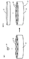
図8は、第2の実施形態に係る核融合炉ブランケットサブユニットを構成する一つの増倍材ブロックの縦断面図である。
[Second Embodiment]
FIG. 8 is a longitudinal sectional view of one multiplier block constituting the fusion reactor blanket subunit according to the second embodiment.
この第2の実施形態においては、第1の実施形態のリチウム‐ベリリウムペレット24に代えて、複数のリチウム化合物ペブル45を用いる。すなわち、各増倍材ブロック22は、粗密収納体23と、粗密収納体23の穴34内に収納されて密閉された複数のリチウム化合物ペブル45とを有する。リチウム化合物ペブル45は、たとえば酸化リチウムからなる。増倍材ブロック22の製造プロセスにおいて、粗密収納容器本体33の上面に形成された複数の穴34それぞれに複数のリチウム化合物ペブル45を充填し、その上から粗密収納容器蓋35を被せて密閉する。その他の構成は第1の実施形態と同様である。
In the second embodiment, a plurality of
酸化リチウムなどのリチウム化合物は、リチウムに比べて反応性が低いので、稠密収納体26(図4)内に封入する必要がない。 Lithium compounds such as lithium oxide are less reactive than lithium and therefore do not need to be enclosed in the dense container 26 (FIG. 4).
この実施形態によれば、リチウム化合物ペブル45が粗密収納体23内に収納されているので、かりにサブユニット筐体14内での冷却水漏洩を想定した場合であっても、水とリチウム化合物との接触を防ぐことができる。これにより、水とリチウム化合物との反応を防ぐことができる。
According to this embodiment, since the lithium compound pebble 45 is housed in the coarse /
[第3の実施形態]
図9は、第3の実施形態に係る核融合炉ブランケットサブユニットの模式的縦断面図である。図10は、図9の核融合炉ブランケットサブユニットのX−X線矢視横断面図である。
[Third Embodiment]
FIG. 9 is a schematic longitudinal sectional view of a nuclear fusion reactor blanket subunit according to the third embodiment. FIG. 10 is a cross-sectional view of the fusion reactor blanket subunit of FIG.
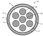
この第3の実施形態は第1の実施形態の変形であって、各増倍材ブロック22において、粗密収納体23内に7個のリチウム−ベリリウムペレット(ペレット)24(24a,24b)が収納されて密閉されている。7個のペレット24はいずれも円柱状であって、互いに同じ形状、同じ大きさであり、いずれもそれぞれの軸がサブユニット筐体14の軸に平行に配置されている。サブユニット筐体14の軸心部に1個のペレット24aが配置され、他の6個のペレット24bが軸心部のペレット24aを周方向間隔が互いに等しくなるように取り囲んで配置されている。このように配置することにより、増倍材ブロック22内に多くのペレット24を収納でき、サブユニット12内のリチウムの量を多くすることができる。
This third embodiment is a modification of the first embodiment, and in each
[第4の実施形態]
図11は、第4の実施形態に係る核融合炉ブランケットサブユニットの横断面図である。
[Fourth Embodiment]
FIG. 11 is a cross-sectional view of a nuclear fusion reactor blanket subunit according to the fourth embodiment.
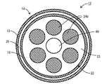
この第4の実施形態は第3の実施形態の変形であって、第3の実施形態の軸心部のペレット24a(図10)に相当するものが存在せず、軸心部に円柱状の中心空隙49が形成されている。6個のペレット24bが、中心空隙49を、周方向間隔が互いに等しくなるように取り囲んで配置されている。さらに、複数の増倍材ブロック22の中心空隙49が軸方向に連通するように、各粗密収納体23の軸心部に貫通孔(図示せず)が形成されている。中心空隙49内にヘリウムガスなどのスイープガスを流すことにより、トリチウムの回収を促進することができる。さらに、スイープガスの流量を増大させれば、ガスによる冷却も可能である。
This fourth embodiment is a modification of the third embodiment, and there is no equivalent to the
上記以外の構成は、第3の実施形態と同様である。 The configuration other than the above is the same as that of the third embodiment.
[第5の実施形態]
図12は、第5の実施形態に係る核融合炉ブランケットサブユニットの模式的縦断面図である。図13は、図12の核融合炉ブランケットサブユニットのXIII−XIII線矢視横断面図である。
[Fifth Embodiment]
FIG. 12 is a schematic longitudinal sectional view of a nuclear fusion reactor blanket subunit according to the fifth embodiment. 13 is a cross-sectional view taken along line XIII-XIII of the fusion reactor blanket subunit of FIG.
この第5の実施形態は第3の実施形態(図9、図10)の変形である。 The fifth embodiment is a modification of the third embodiment (FIGS. 9 and 10).
この第5の実施形態では、サブユニット筐体14の半球状部50内に、サブユニット筐体14の円筒部に配置された増倍材ブロック22よりも軸方向に薄い薄型円板状の増倍材ブロック122が配置されている。この薄型増倍材ブロック122を構成する粗密収納体123およびペレット124はサブユニット筐体14の円筒部に配置された増倍材ブロック22よりも軸方向に薄い(短い)ものとなる。薄型増倍材ブロック122の軸に垂直な断面内の7個のペレット124の配置関係は円筒部の増倍材ブロック22の7個のペレット24の配置関係(図10)と同様である。
In the fifth embodiment, a thin disk-shaped increase in the axial direction is thinner in the
サブユニット筐体14の半球状部50内で薄型増倍材ブロック122よりもさらに先端近くには、薄型増倍材ブロック122よりも直径の小さい小型増倍材ブロック222が配置されている。小型増倍材ブロック222の粗密収納体223は、薄型増倍材ブロック122の粗密収納体123よりも直径が小さいが厚さは粗密収納体123と同様である。小型増倍材ブロック222には3個のペレット224が含まれ、小型増倍材ブロック222の軸心の周りに周方向に等間隔に配置されている。各ペレット224の形状や大きさは薄型増倍材ブロック122のペレット124と同様である。
In the
半球状部50内で、薄型増倍材ブロック122および小型増倍材ブロック222が配置された以外の隙間には、多数のベリリウム粒36が充填されている。
In the
上記以外の構造は第3の実施形態と同様である。 Structures other than those described above are the same as in the third embodiment.
この第5の実施形態によれば、サブユニット筐体14の半球状部50内にペレット124,224を配置するので、サブユニット12内のペレット24,124,224の量を増やすことができる。
According to the fifth embodiment, since the
なお、この実施形態において、半球状部50内のペレット124,224のリチウム含有体25(図4)のリチウム含有量を、円筒部のペレット24のリチウム含有体25のリチウム含有量よりも大きくしてもよい。リチウム含有体25のリチウム含有量は、ベリリウム多孔質体31(図5)の空隙率およびそこへのリチウム含浸量の調整によって調整することができる。
In this embodiment, the lithium content of the lithium-containing body 25 (FIG. 4) of the
[第6の実施形態]
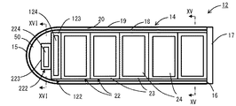
図14は、第6の実施形態に係る核融合炉ブランケットサブユニットの模式的縦断面図である。図15は、図14の核融合炉ブランケットサブユニットのXV−XV線矢視横断面図である。図16は、図14の核融合炉ブランケットサブユニットのXVI−XVI線矢視横断面図である。
[Sixth Embodiment]
FIG. 14 is a schematic longitudinal sectional view of a nuclear fusion reactor blanket subunit according to the sixth embodiment. FIG. 15 is a transverse cross-sectional view of the fusion reactor blanket subunit of FIG. 14 taken along line XV-XV. 16 is a transverse cross-sectional view of the fusion reactor blanket subunit of FIG. 14 taken along line XVI-XVI.
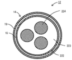
この第6の実施形態は第5の実施形態の変形である。この実施形態では、各増倍材ブロック22,122,222の中央に比較的大きなリチウム‐ベリリウムペレット24,124,224が1個だけ配置されている。各ペレット24,124,224の大きさは第5の実施形態の場合よりも大きいが、構造は第5の実施形態と同様である。
The sixth embodiment is a modification of the fifth embodiment. In this embodiment, only one relatively large lithium-
粗密収納体23,123,223の構造は第5の実施形態の場合と同様である。
The structure of the coarse /
この実施形態によれば、ペレット24,124,224の個数を減らすことができ、加工量を減らすことができるとともに、リチウムの量を増やすことができる。
According to this embodiment, the number of
[第7の実施形態]
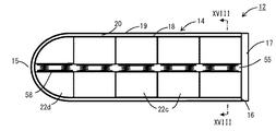
図17は、第7の実施形態に係る核融合炉ブランケットサブユニットの模式的縦断面図である。図18は、図17の核融合炉ブランケットサブユニットのXVIII−XVIII線矢視横断面図である。図19は、第7の実施形態に係る核融合炉ブランケットサブユニットの組み立てプロセスを示す説明図である。図20は、第7の実施形態に係る核融合炉ブランケットサブユニットにおける先端増倍材ブロックとばねユニットとの、サブユニット筐体への挿入前の状況を示す説明図である。図21は、第7の実施形態に係る核融合炉ブランケットサブユニットにおける主増倍材ブロックとばねユニットとの、サブユニット筐体への挿入前の状況を示す説明図である。
[Seventh Embodiment]
FIG. 17 is a schematic longitudinal sectional view of a nuclear fusion reactor blanket subunit according to the seventh embodiment. 18 is a cross-sectional view taken along line XVIII-XVIII of the fusion reactor blanket subunit of FIG. FIG. 19 is an explanatory diagram showing an assembly process of the fusion reactor blanket subunit according to the seventh embodiment. FIG. 20 is an explanatory diagram showing a state before the tip multiplier block and the spring unit in the fusion reactor blanket subunit according to the seventh embodiment are inserted into the subunit housing. FIG. 21 is an explanatory diagram illustrating a state before the main multiplier block and the spring unit in the fusion reactor blanket subunit according to the seventh embodiment are inserted into the subunit housing.
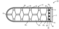
この実施形態の核融合炉ブランケットサブユニット(サブユニット)12は、サブユニット筐体14と、サブユニット筐体14内に収納された複数の増倍材ブロック22c,22dと、底板17とを有する。サブユニット筐体14および底板17の構造は、前述の第1〜第6の実施形態と同様である。
The fusion reactor blanket subunit (subunit) 12 of this embodiment includes a
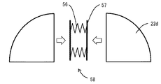
増倍材ブロック(主増倍材ブロック)22cは、サブユニット筐体14の先端を除く円筒部に挿入されていて、円柱形を、その軸を通る平面(分割面)で2分割した略半円柱状である。2個の増倍材ブロック22cがその分割面で対向し、それらの間にばねユニット55が配置されている。ばねユニット55は、並列に配置された2個の圧縮ばね56と、これらの圧縮ばね56をはさんで互いに平行に配置された2枚の当て板57とを有する。2個の増倍材ブロック22cが、当て板57を介して圧縮ばね56によって、互いに離れる方向に押され、サブユニット筐体14の内壁18に押し付けられている。このようにばねユニット55をはさんで配置された2個の増倍材ブロック22cの組が、軸方向に複数組(図示の例では4組)配列されている。
The multiplier block (main multiplier block) 22c is inserted into the cylindrical portion excluding the tip of the
増倍材ブロック(先端増倍材ブロック)22dは、サブユニット筐体14の先端の半球状部50に挿入されるものであり、半球形を、その軸を通る平面(分割面)で2分割した略14球状である。2個の増倍材ブロック22dがその分割面で対向し、それらの間にばねユニット58が配置されている。ばねユニット58の構造はばねユニット55の構造と同様である。2個の増倍材ブロック22dが、ばねユニット58によって、互いに離れる方向に押され、サブユニット筐体14の内壁18に押し付けられている。
The multiplier block (tip multiplier block) 22d is inserted into the
増倍材ブロック22c,22dは、たとえば第1〜第6の実施形態のいずれかにおける増倍材ブロック22と同様のものである。ただし、増倍材ブロック22c,22dの外形は、第1〜第6の実施形態における増倍材ブロック22の外形と相違する。
The multiplier blocks 22c and 22d are similar to the
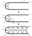
この実施形態のサブユニットの組み立てに当たっては、図19、図20に示すように、初めに、サブユニット筐体14に底板17を取り付ける前の状態で、開放された第2の端部16から、14球状の2個の増倍材ブロック22dとばねユニット58とを挿入して、半球状部50に配置する。ばねユニット58は、挿入時には圧縮して、半球状部50に配置された後には2個の増倍材ブロック22dをサブユニット筐体14の内壁18に押し付けるようにする。
In assembling the subunit of this embodiment, as shown in FIGS. 19 and 20, first, in the state before the
図20において、白抜き矢印は、組立作業における部品の動きの方向を表している。以下の組立手順を説明する図面でも同様である。 In FIG. 20, the white arrow represents the direction of movement of the component in the assembly work. The same applies to the drawings describing the following assembly procedure.
つぎに、2個の増倍材ブロック22cとその間のばねユニット55とからなる組を、順次、サブユニット筐体14内に挿入する。このとき、図21に示すように、ばねユニット55の圧縮ばね56を圧縮した状態で挿入する。その後、サブユニット筐体14の開放された第2の端部16に底板17を取り付けて密封して、図17に示す状態とする。
Next, a set of two
この実施形態によれば、核融合炉の通常運転時に、増倍材ブロック22c,22dがサブユニット筐体14の内壁18に押し付けられているので、増倍材ブロック22c,22dからの熱が接触熱伝導により内壁18に伝達され、増倍材ブロック22c,22dの冷却を効率的に行うことができる。
According to this embodiment, since the multiplier blocks 22c and 22d are pressed against the
[第8の実施形態]
図22は、第8の実施形態に係る核融合炉ブランケットサブユニットの模式的横断面図である。
[Eighth Embodiment]
FIG. 22 is a schematic cross-sectional view of a fusion reactor blanket subunit according to the eighth embodiment.
この実施形態は第7の実施形態の変形であって、増倍材ブロック22cの分割面の向きすなわちばねユニット55の向きと、増倍材ブロック22dでの分割面の向きすなわちばねユニット58の向きが軸方向から見て揃っていない。より具体的には、各分割面がサブユニット筐体14の軸を含むように配置され、しかも、軸方向位置に応じて異なる周方向位置(角度位置)に配置されている。
This embodiment is a modification of the seventh embodiment, and the direction of the dividing surface of the
その他の構成は第7の実施形態と同様である。 Other configurations are the same as those of the seventh embodiment.
この第8の実施形態によれば、増倍材ブロック22cおよび増倍材ブロック22dでの分割面に生じる空隙の位置が軸方向に揃っていない。そのため、軸方向から見て、軸心部分を除き、その空隙が第1の端部15から第2の端部16まで直線的に延びている部分はない。したがって、核融合プラズマ13から発せられた中性子線が底板17まで達することは少ない。
According to the eighth embodiment, the positions of the gaps formed on the dividing surfaces of the
[第9の実施形態]
図23は、第9の実施形態に係る核融合炉ブランケットサブユニットの模式的横断面図である。
[Ninth Embodiment]
FIG. 23 is a schematic cross-sectional view of a nuclear fusion reactor blanket subunit according to the ninth embodiment.
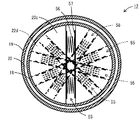
この実施形態は第8の実施形態の変形であって、サブユニット筐体14の半球状部50以外の部分の各軸方向位置に、増倍材ブロック22e,22f,22g,22hが配置されている。増倍材ブロック22e,22f,22g,22hは軸方向に平面的に広がる分割面で互いに対向していて、それらが対向する位置にばねユニット60が配置されている。ばねユニット60の構造は、第8の実施形態におけるばねユニット55と同様である。
This embodiment is a modification of the eighth embodiment, and the
増倍材ブロック22eと増倍材ブロック22fとは同じ形状であるが、増倍材ブロック22g,22hの形状は増倍材ブロック22e,22fとは異なる形状である。この実施形態では、サブユニット筐体14の軸心部には増倍材ブロック22gが存在し、空隙にはなっていない。サブユニット筐体14内の軸方向位置に応じて、増倍材ブロック22e,22f,22g,22hの周方向配置位置がずれている(図示せず)。そのため、軸方向から見て、軸心部分を含めて、増倍材ブロック22e,22f,22g,22h同士の間の隙間が第1の端部15から第2の端部16まで直線的に延びている部分はない。したがって、核融合プラズマ13から発せられた中性子線が底板17まで達することは少ない。
The
[第10の実施形態]
図24は、第10の実施形態に係る核融合炉ブランケットサブユニットの模式的縦断面図である。図25は、第10の実施形態に係る核融合炉ブランケットサブユニットのばねユニットの、サブユニット筐体への挿入前の状況を示す部分拡大正面図である。
[Tenth embodiment]
FIG. 24 is a schematic longitudinal sectional view of a nuclear fusion reactor blanket subunit according to the tenth embodiment. FIG. 25 is a partially enlarged front view showing a state before the spring unit of the fusion reactor blanket subunit according to the tenth embodiment is inserted into the subunit housing.
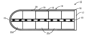
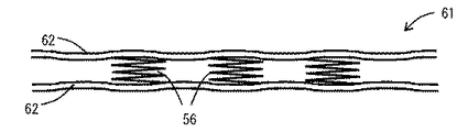
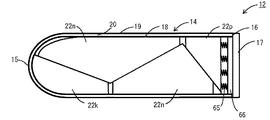
この実施形態は第7の実施形態(図17〜図21)の変形である。一つのばねユニット61が、サブユニット筐体14の第1の端部15から第2の端部16まで、軸方向に長くのびている。ばねユニット61は、互いに平行に軸方向に延びる1対の当て板62と、これらの当て板62間にはさまれて、それぞれが当て板62の間隔を広げる向きに当て板62を押す複数の圧縮ばね56とを有する。当て板62は、軸方向に波形となっており、軸方向に撓みやすくなっている。
This embodiment is a modification of the seventh embodiment (FIGS. 17 to 21). One
この第7の実施形態のサブユニットの組み立てに当たり、サブユニット筐体14の第2の端部16が開放した状態で、サブユニット筐体14内に、第2の端部16から増倍材ブロック22c,22dを順次挿入する。その後に、第2の端部16からばねユニット61を挿入する。その後、サブユニット筐体14の開放された第2の端部16に底板17を取り付けて密封する。このような組み立て手順をとることにより、組み立て時の省力を図ることができる。
In assembling the subunit of the seventh embodiment, the multiplier member block is formed from the
また、当て板62が波形となっているため、増倍材ブロック22c,22dの寸法公差などに応じて当て板62が撓み、増倍材ブロック22c,22dを確実に径方向外向きに押し、増倍材ブロック22c,22dとサブユニット筐体14の内壁18との間の接触を確保することができる。それにより、増倍材ブロック22c,22d内の熱をサブユニット筐体14の内壁18に確実に逃がすことができる。
Further, since the
[第11の実施形態]
図26は、第11の実施形態に係る核融合炉ブランケットサブユニットの模式的縦断面図である。図27は、第11の実施形態に係る核融合炉ブランケットサブユニットの組み立てプロセスを示す説明図である。
[Eleventh embodiment]
FIG. 26 is a schematic longitudinal sectional view of a nuclear fusion reactor blanket subunit according to the eleventh embodiment. FIG. 27 is an explanatory diagram showing an assembly process of the fusion reactor blanket subunit according to the eleventh embodiment.
第11の実施形態は、第7〜第10の実施形態の変形である。 The eleventh embodiment is a modification of the seventh to tenth embodiments.
この第11の実施形態では、円筒状のサブユニット筐体14内に、軸をはさんで互いに対向するほぼ半円柱状の増倍材ブロック22iの対が複数対、軸方向に配列されている。これら複数対の増倍材ブロック22iの対によって軸方向にはさまれる軸方向中央位置に、縦断面形状がほぼひし形の増倍材ブロック22jが配置されている。
In the eleventh embodiment, a plurality of pairs of substantially
増倍材ブロック22iと増倍材ブロック22jとの接触面は軸方向に対して傾斜している。また、増倍材ブロック22i同士が接触することはなく、増倍材ブロック22j同士が接触することもないように構成されている。
The contact surface between the
サブユニット筐体14の第2の端部16に最も近い位置の増倍材ブロック22jの第2の端部16側に接してばねユニット65が配置され、ばねユニット65の軸方向外側に円板状の雄ねじ板66が配置され、雄ねじ板66の軸方向外側に底板17が取り付けられている。
A
ばねユニット65は、軸方向に垂直に広がる2枚の円板状の当て板68と、これらの当て板68にはさまれて軸方向に押圧力を生じるように配置された複数の圧縮ばね69とを有する。雄ねじ板66の外周には雄ねじ70が形成され、サブユニット筐体14の第2端部16近くに形成された雌ねじ71と螺合する。雄ねじ板66をねじ込むことにより、ばねユニット65が第1の端部15側に押される。底板17は、サブユニット筐体14の第2の端部16に溶接固定され、密封されている。
The
ばねユニット65は、サブユニット筐体14の第2の端部16に最も近い位置の増倍材ブロック22jを第1の端部15側に、常時押している。その結果、他の増倍材ブロック22jも、また、増倍材ブロック22iも互いに軸方向に押される。この時、増倍材ブロック22iと増倍材ブロック22jとの接触面が軸方向に対して傾斜していることから、ほぼ半円柱状の増倍材ブロック22iが径方向外側に向かう力を受けることになる。これにより、増倍材ブロック22iはサブユニット筐体14の内壁18に押し付けられる。したがって、増倍材ブロック22iとサブユニット筐体14の内壁18との間で熱伝導による伝熱が促進される。また、互いに隣接する増倍材ブロック22iと増倍材ブロック22jとの間で互いに押し付けられることから、これらの間でも熱伝導が促進される。
The
図27に示すように、この第11の実施形態のサブユニットの組み立てに当たっては、サブユニット筐体14の第2の端部16が開放した状態で、サブユニット筐体14内に、増倍材ブロック22i,22jを、第1の端部15に近い位置のものから順に、第2の端部16から挿入していく。そして、最後に第2の端部16に最も近い位置に配置すべき増倍材ブロック22jを挿入する。その後に、ばねユニット65を挿入し、その後に、雄ねじ板66をねじ込み、ばねユニット65の圧縮ばね69を圧縮して圧縮力が生じるようにする。その後に、底板17を、サブユニット筐体14の第2の端部16に溶接固定して密閉して、図26に示す状態にする。
As shown in FIG. 27, in assembling the subunit of the eleventh embodiment, the multiplier member is placed in the
この第11の実施形態では、サブユニット筐体14内に増倍材ブロック22i,22jを挿入した後にばねユニット65を挿入するものであり、しかもばねユニット65を軸方向に押し付ければよいので、組み立てが容易であり、組み立て時の省力を図ることができる。
In the eleventh embodiment, the
[第12の実施形態]
図28は、第12の実施形態に係る核融合炉ブランケットサブユニットの模式的縦断面図である。
[Twelfth embodiment]
FIG. 28 is a schematic longitudinal sectional view of a nuclear fusion reactor blanket subunit according to the twelfth embodiment.
第12の実施形態は第11の実施形態の変形である。 The twelfth embodiment is a modification of the eleventh embodiment.
この第12の実施形態では、円筒状のサブユニット筐体14内に、増倍材ブロック22k,22m,22n,22pが軸方向に配列されている。増倍材ブロック22kと増倍材ブロック22mとの接触面、増倍材ブロック22mと増倍材ブロック22nとの接触面、増倍材ブロック22nと増倍材ブロック22pとの接触面はいずれも軸方向に対して傾斜している。また、増倍材ブロック22kと増倍材ブロック22nとは直接触せず、増倍材ブロック22mと増倍材ブロック22pとは直接接触していない。
In the twelfth embodiment, multiplier blocks 22k, 22m, 22n, and 22p are arranged in the axial direction in a
サブユニット筐体14の第2の端部16に最も近い位置の増倍材ブロック22pの第2の端部16側に接してばねユニット65が配置され、ばねユニット65の軸方向外側に円板状の雄ねじ板66が配置され、雄ねじ板66の軸方向外側に底板17が取り付けられている。
A
ばねユニット65が増倍材ブロック22pを第1の端部15側に押すことにより、増倍材ブロック22pが増倍材ブロック22nを第1の端部15側に押し、さらにそれが増倍材ブロック22mを第1の端部15側に押し、さらにそれが増倍材ブロック22kを第1の端部15側に押す。その際に、互いの接触面が軸方向に対して傾斜していることにより、増倍材ブロック22k,22m,22n,22pがそれぞれ、サブユニット筐体14の内壁18に向かって押し付けられる向きの力を受ける。
When the
この第12の実施形態によれば、ばねユニット65による軸方向の押し付け力によって、増倍材ブロック22k,22m,22n,22pがサブユニット筐体14の内壁18に向かって押し付けられる。それにより、第11の実施形態と同様の効果を得ることができる。
According to the twelfth embodiment, the multiplying
[第13の実施形態]
図29は、第13の実施形態に係る核融合炉ブランケットサブユニットの模式的縦断面図である。図30は、第13の実施形態に係る核融合炉ブランケットサブユニットの組み立てプロセスを示す説明図である。
[Thirteenth embodiment]
FIG. 29 is a schematic longitudinal sectional view of a nuclear fusion reactor blanket subunit according to the thirteenth embodiment. FIG. 30 is an explanatory diagram showing an assembly process of the fusion reactor blanket subunit according to the thirteenth embodiment.
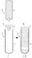
ほぼ円筒状のサブユニット筐体14aは、第7〜第12の実施形態のサブユニット筐体14と同様に、第1の端部15が半球状に突出し、第2の端部16は、円板状の底板17によって密閉されている。
As in the
サブユニット筐体14aの第1の端部15付近の半球状部50内に、この半球の形状に合わせて成形された半球状増倍材ブロック22qが配置されている。
A
サブユニット筐体14aの半球状部50を除く円筒部内に、円柱状増倍材ブロック22rが配置されている。サブユニット筐体14aの半球状部50を除く円筒部の内面には雌ねじ75が形成され、円柱状増倍材ブロック22rの外面には、雌ねじ75と螺合する雄ねじ76が形成されている。
A
この第13の実施形態のサブユニットの組み立てに当たっては、初めに、サブユニット筐体14aの第2の端部16が開放した状態で、サブユニット筐体14a内に、半球状増倍材ブロック22qを挿入し、つぎに、円柱状増倍材ブロック22rをサブユニット筐体14a内にねじ込んでいき、円柱状増倍材ブロック22rで半球状増倍材ブロック22qを第1の端部15に向けて押し付ける。その後に、底板17を、サブユニット筐体14aの第2の端部16に溶接固定して密閉する。
In assembling the subunit of the thirteenth embodiment, first, the
この実施形態によれば、半球状増倍材ブロック22qと円柱状増倍材ブロック22rとが軸方向に押し付けられるとともに、半球状増倍材ブロック22qがサブユニット筐体14aの第1の端部15に押し付けられ、さらに円柱状増倍材ブロック22rの雄ねじ76とサブユニット筐体14aの雌ねじ75とが螺合することによりこれらが確実に接触し、固体接触による熱伝導が確保される。しかも、組み立て作業が容易であって、省力を図ることができる。
According to this embodiment, the
この第13の実施形態の変形として、半球状増倍材ブロック22qと円柱状増倍材ブロック22rとを初めから一体で成型してもよい。その場合は、組立作業がさらに容易である。
As a modification of the thirteenth embodiment, the
[第14の実施形態]
図31は、第14の実施形態に係る核融合炉ブランケットサブユニットの要部拡大縦断面図である。
[Fourteenth embodiment]
FIG. 31 is an enlarged vertical sectional view showing a principal part of a fusion reactor blanket subunit according to the fourteenth embodiment.
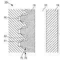
この第14の実施形態は第13の実施形態の変形である。第14の実施形態では、第13の実施形態(図29)と同様に、サブユニット筐体14aの円筒部の雌ねじ75と円柱状増倍材ブロック22rの雄ねじ76とが螺合する。この第14の実施形態の雌ねじ75および雄ねじ76では、通常の機械的要素としてのねじに必要なねじの谷の深さよりも深い谷が形成されている。それにより、互いに螺合するねじの山と谷の間に、通常の機械的要素としてのねじにおける空隙よりも大きな螺旋状のガス空隙80,81が形成されている。さらに、雌ねじ75の谷と雄ねじ76の山との間に形成されるガス空隙81の中央に向かって、雄ねじ76の山から突出する突出部82が形成されている。
The fourteenth embodiment is a modification of the thirteenth embodiment. In the fourteenth embodiment, as in the thirteenth embodiment (FIG. 29), the
螺旋状のガス空隙80,81によりガス流路が形成される。このガス流路に冷却用のガスを流通させることにより、サブユニット筐体14aの内側を冷却することができる。固体同士の接触熱伝導特性は、供用中の固体材料の性状変化によって変動する可能性があるが、流体であれば安定した除熱特性を維持することができる。また、突出部82の存在により、ガス空隙81に接する固体表面積が大きくなり、ガス空隙81内のガスと固体との熱伝達が促進される。
A gas flow path is formed by the
この第14の実施形態の変形例として、雌ねじ75の山と雄ねじ76の谷との間に形成されるガス空隙80の中央に向かって、雌ねじ75の山から突出する突出部(図示せず)が形成されるようにしてもよい。
As a modification of the fourteenth embodiment, a protrusion (not shown) that protrudes from the peak of the
[他の実施形態]
上記実施形態の説明で、サブユニット筐体14は、ほぼ円筒状で第1の端部15が半円球状とした。しかし、本発明はこのような構成に限定されない。たとえば、サブユニット筐体が直方体であってもよい。
[Other Embodiments]
In the description of the above embodiment, the
上述の各実施形態の特徴を適宜組み合わせることもできる。 The features of the embodiments described above can be combined as appropriate.
以上、本発明のいくつかの実施形態を説明したが、これらの実施形態は、例として提示したものであり、発明の範囲を限定することは意図していない。これら実施形態は、その他の様々な形態で実施されることが可能であり、発明の要旨を逸脱しない範囲で、種々の省略、置き換え、変更を行うことができる。これら実施形態やその変形は、発明の範囲や要旨に含まれると同様に、特許請求の範囲に記載された発明とその均等の範囲に含まれるものである。 As mentioned above, although some embodiment of this invention was described, these embodiment is shown as an example and is not intending limiting the range of invention. These embodiments can be implemented in various other forms, and various omissions, replacements, and changes can be made without departing from the spirit of the invention. These embodiments and their modifications are included in the scope and gist of the invention, and are also included in the invention described in the claims and the equivalents thereof.
11…真空容器、 12…核融合炉ブランケットサブユニット(サブユニット)、 13…核融合プラズマ、 14,14a…サブユニット筐体、 15…第1の端部、 16…第2の端部、 17…底板、 18…内壁、 19…外壁、 20…冷却水流路、 21…冷却水配管、 22,22c,22d,22e,22f,22g,22h,22i,22j,22k,22m,22n,22p,22q,22r,122,222…増倍材ブロック、 23,123,223…粗密収納体、 24,24a,24b、124,224…リチウム‐ベリリウムペレット(ペレット)、 25…リチウム含有体、 26…稠密収納体、 27…稠密収納容器本体、 28…稠密収納容器蓋、 30…ベリリウム粒、 31…ベリリウム多孔質体、 32…リチウム板、 33…粗密収納容器本体、 34…穴(くぼみ)、 35…粗密収納容器蓋、 36、37…ベリリウム粒、 40…ガス配管、 45…リチウム化合物ペブル、 49…中心空隙、 50…半球状部、 55…ばねユニット、 56…圧縮ばね、 57…当て板、 58…ばねユニット、 60…ばねユニット、 61…ばねユニット、 62…当て板、 65…ばねユニット、 66…雄ねじ板、 68…当て板、 69…圧縮ばね、 70…雄ねじ、 71,75…雌ねじ、 76…雄ねじ、 80,81…ガス空隙、 82…突出部
DESCRIPTION OF
Claims (19)
前記リチウム含有体を収納して密閉するベリリウム製の稠密収納体を備えた増倍材ブロックと、
前記増倍材ブロックを収納して密閉するサブユニット筐体と、
を有し、
前記サブユニット筐体の外側と内側とを連絡して前記サブユニット筐体内を冷却する冷却水が流れる冷却水流路が形成され、
前記サブユニット筐体の外側と内側とを連絡して前記サブユニット筐体内で生じたトリチウムを前記サブユニット筐体外に搬送するガス流路が形成されていること、
を特徴とする核融合炉ブランケットサブユニット。 A lithium-containing body containing lithium or a lithium compound;
A multiplier block comprising a dense bead made of beryllium that contains and seals the lithium-containing body;
A subunit housing that houses and seals the multiplier block;
Have
A cooling water flow path is formed through which cooling water that cools the inside of the subunit housing through communication between the outside and the inside of the subunit housing is formed.
A gas flow path is formed that communicates the outside and inside of the subunit housing to convey tritium generated in the subunit housing to the outside of the subunit housing;
Fusion reactor blanket subunit characterized by.
前記増倍材ブロックは前記軸方向に複数個が配列されていて、前記増倍材ブロックのそれぞれが前記軸と同軸の円板状であって、
前記粗密収納体それぞれ内で、前記軸に垂直な平面内で、前記軸中心位置に配置された1個の前記稠密収納体を囲んで他の6個の前記稠密収納体が周方向に等間隔に配置されていること、
を特徴とする請求項4に記載の核融合炉ブランケットサブユニット。 The subunit housing is substantially cylindrical extending in the axial direction;
A plurality of the multiplying material blocks are arranged in the axial direction, and each of the multiplying material blocks has a disk shape coaxial with the shaft,
Within each of the dense storage bodies, in a plane perpendicular to the axis, surrounds one of the dense storage bodies arranged at the axial center position, and the other six dense storage bodies are equally spaced in the circumferential direction. Being placed in the
The fusion reactor blanket subunit according to claim 4.
前記増倍材ブロックは前記軸方向に複数個が配列されていて、前記増倍材ブロックのそれぞれが前記軸と同軸の円板状であって、
前記粗密収納体それぞれ内で、前記軸に垂直な平面内で、前記軸中心位置に中心空隙を形成して当該中心空隙の周りを取り囲むように6個の前記稠密収納体が周方向に等間隔に配置されていて、
前記中心空隙が前記ガス流路の一部を構成していること、
を特徴とする請求項4に記載の核融合炉ブランケットサブユニット。 The interior of the subunit housing is substantially cylindrical extending in the axial direction,
A plurality of the multiplying material blocks are arranged in the axial direction, and each of the multiplying material blocks has a disk shape coaxial with the shaft,
In each of the dense storage bodies, six dense storage bodies are equally spaced in the circumferential direction so as to form a central gap at the axial center position and surround the central gap in a plane perpendicular to the axis. Are located in
The central gap forms part of the gas flow path;
The fusion reactor blanket subunit according to claim 4.
前記リチウム含有体を収納して密閉するベリリウム製の粗密収納体を備えた増倍材ブロックと、
前記増倍材ブロックを収納して密閉するサブユニット筐体と、
を有し、
前記サブユニット筐体の外側と内側とを連絡して前記サブユニット筐体内を冷却する冷却水が流れる冷却水流路が形成され、
前記サブユニット筐体の外側と内側とを連絡して前記サブユニット筐体内で生じたトリチウムを前記サブユニット筐体外に搬送するガス流路が形成されていること、
を特徴とする核融合炉ブランケットサブユニット。 A lithium-containing body containing a lithium compound;
A multiplier block comprising a beryllium coarse / dense container for containing and sealing the lithium-containing body;
A subunit housing that houses and seals the multiplier block;
Have
A cooling water flow path is formed through which cooling water that cools the inside of the subunit housing through communication between the outside and the inside of the subunit housing is formed.
A gas flow path is formed that communicates the outside and inside of the subunit housing to convey tritium generated in the subunit housing to the outside of the subunit housing;
Fusion reactor blanket subunit characterized by.
前記冷却水流路は、前記内壁と前記外壁との間に形成されていること、を特徴とする請求項1ないし請求項7のいずれか一項に記載の核融合炉ブランケットサブユニット。 The subunit housing has an inner wall and an outer wall surrounding the inner wall,
The fusion reactor blanket subunit according to any one of claims 1 to 7, wherein the cooling water flow path is formed between the inner wall and the outer wall.
前記冷却水流路は、前記内壁と前記外壁との間に形成され、
前記内壁の内側に、前記増倍材ブロックが複数個配置され、
前記複数個の増倍材ブロックの間に配置されて前記複数個の増倍材ブロックを前記内壁の内面に押し付ける圧縮ばねをさらに有すること、
を特徴とする請求項1ないし請求項9のいずれか一項に記載の核融合炉ブランケットサブユニット。 The subunit housing has an inner wall and an outer wall surrounding the inner wall,
The cooling water flow path is formed between the inner wall and the outer wall,
A plurality of the multiplier blocks are arranged inside the inner wall,
A compression spring disposed between the plurality of multiplier blocks and pressing the plurality of multiplier blocks against the inner surface of the inner wall;
A fusion reactor blanket subunit according to any one of claims 1 to 9.
前記圧縮ばねによって生じる前記複数個の増倍材ブロックの間の軸方向に延びる空隙の径方向または周方向の位置が軸方向位置によってずれるように前記複数個の増倍材ブロックが配置されていること、
を特徴とする請求項10に記載の核融合炉ブランケットサブユニット。 The subunit housing has a cylindrical shape with both ends closed and extending in the axial direction,
The plurality of multiplier blocks are arranged such that the radial or circumferential positions of the gaps extending in the axial direction between the plurality of multiplier blocks generated by the compression springs are shifted depending on the axial position. about,
The fusion reactor blanket subunit according to claim 10.
前記圧縮ばねが複数個並列に配置され、
前記圧縮ばねと前記増倍材ブロックとの間に介在し、前記複数個の圧縮ばねをはさんで軸方向に互いに平行に延びる、2枚の当て板をさらに有し、
前記当て板は、軸方向にたわみやすいように波形状であること、
を特徴とする請求項10に記載の核融合炉ブランケットサブユニット。 The inside of the subunit housing has a cylindrical shape extending in the axial direction,
A plurality of the compression springs are arranged in parallel,
Further comprising two contact plates that are interposed between the compression spring and the multiplier block and extend parallel to each other in the axial direction across the plurality of compression springs;
The caulking plate has a wave shape so as to be easily bent in the axial direction;
The fusion reactor blanket subunit according to claim 10.
前記サブユニット筐体は、核融合プラズマに対向する第1の端部と前記第1の端部の反対側の第2の端部との間で軸方向に延びる筒状であって、
前記冷却水流路は、前記内壁と前記外壁との間に形成され、
前記内壁の内側に、前記増倍材ブロックが複数個配置され、
前記サブユニット筐体の前記第2の端部に配置されて、前記複数個の増倍材ブロックのうちの第1の増倍材ブロックを前記第1の端部に向けて付勢する軸方向圧縮ばね、をさらに有し、
前記第1の増倍材ブロックと、前記複数個の増倍材ブロックのうちの前記第1の増倍材ブロックとは異なる第2の増倍材ブロックとが、前記軸方向に対して傾斜する傾斜接触面で互いに接触していて、
前記軸方向圧縮ばねが前記第1の増倍材ブロックを前記第1の端部に向けて付勢することにより、前記第2の増倍材ブロックが前記内壁に向けて付勢されるように構成されていること、
を特徴とする請求項1ないし請求項9のいずれか一項に記載の核融合炉ブランケットサブユニット。 The subunit housing has an inner wall and an outer wall surrounding the inner wall,
The subunit housing has a cylindrical shape extending in the axial direction between a first end facing the fusion plasma and a second end opposite to the first end,
The cooling water flow path is formed between the inner wall and the outer wall,
A plurality of the multiplier blocks are arranged inside the inner wall,
An axial direction that is disposed at the second end of the subunit housing and biases the first multiplier block of the plurality of multiplier blocks toward the first end. A compression spring,
The first multiplier block and the second multiplier block different from the first multiplier block among the plurality of multiplier blocks are inclined with respect to the axial direction. In contact with each other at the inclined contact surface,
The axial compression spring biases the first multiplier block toward the first end so that the second multiplier block is biased toward the inner wall. That it is configured,
A fusion reactor blanket subunit according to any one of claims 1 to 9.
前記サブユニット筐体は、核融合プラズマに対向する第1の端部と前記第1の端部の反対側の第2の端部の間で軸方向に延びる円筒状であって、
前記冷却水流路は、前記内壁と前記外壁との間に形成され、
前記内壁の内面に雌ねじが形成され、
前記増倍材ブロックは、円柱状増倍材ブロックを含み、前記円柱状増倍材ブロックに、前記内壁の前記雌ねじと螺合する雄ねじが形成されていること
を特徴とする請求項1ないし請求項9のいずれか一項に記載の核融合炉ブランケットサブユニット。 The subunit housing has an inner wall and an outer wall surrounding the inner wall,
The subunit housing has a cylindrical shape extending in an axial direction between a first end facing the fusion plasma and a second end opposite to the first end,
The cooling water flow path is formed between the inner wall and the outer wall,
An internal thread is formed on the inner surface of the inner wall,
The said multiplication material block contains a cylindrical multiplication material block, The external thread which engages with the said internal thread of the said inner wall is formed in the said cylindrical multiplication material block. The fusion reactor blanket subunit according to any one of Items 9.
を備えることを特徴とする核融合炉ブランケット。 A plurality of fusion reactor blanket subunits according to any one of claims 1 to 15, arranged along the inner surface of a vacuum vessel confining plasma.
A fusion reactor blanket characterized by comprising:
ベリリウム製の稠密収納体内に前記リチウム含有体を収納して密閉してリチウム‐ベリリウムペレットを作成するペレット作成工程と、
前記ペレット作成工程の後にサブユニット筐体内に前記リチウム‐ベリリウムペレットを収納して密閉するサブユニット筐体収納工程と、
を有することを特徴とする核融合炉ブランケットサブユニット製造方法。 A lithium-containing body creation step of creating a lithium-containing body containing lithium or a lithium compound by impregnating a porous beryllium body with lithium or a lithium compound;
A pellet making step of storing the lithium-containing body in a dense beryllium container and sealing it to create a lithium-beryllium pellet;
A subunit housing housing step of housing and sealing the lithium-beryllium pellet in the subunit housing after the pellet making step;
A method for manufacturing a nuclear fusion reactor blanket subunit.
前記サブユニット筐体収納工程は、前記増倍材ブロック作成工程の後に、前記サブユニット筐体内に前記増倍材ブロックを収納して密閉するものであること、を特徴とする請求項17または請求項18に記載の核融合炉ブランケットサブユニット製造方法。 The lithium-beryllium pellets are housed and sealed in a coarse / dense beryllium container having a density lower than that of the dense container, further comprising a multiplier block creating step for creating a multiplier block,
The said subunit housing | casing accommodation process accommodates and seals the said multiplication material block in the said subunit housing | casing after the said multiplication material block preparation process, The Claim 17 or Claim characterized by the above-mentioned. Item 19. A fusion reactor blanket subunit manufacturing method according to Item 18.
Priority Applications (1)
| Application Number | Priority Date | Filing Date | Title |
|---|---|---|---|
| JP2016139327A JP6704811B2 (en) | 2016-07-14 | 2016-07-14 | Fusion reactor blanket subunit, manufacturing method thereof, and fusion reactor blanket |
Applications Claiming Priority (1)
| Application Number | Priority Date | Filing Date | Title |
|---|---|---|---|
| JP2016139327A JP6704811B2 (en) | 2016-07-14 | 2016-07-14 | Fusion reactor blanket subunit, manufacturing method thereof, and fusion reactor blanket |
Publications (2)
| Publication Number | Publication Date |
|---|---|
| JP2018009890A true JP2018009890A (en) | 2018-01-18 |
| JP6704811B2 JP6704811B2 (en) | 2020-06-03 |
Family
ID=60995442
Family Applications (1)
| Application Number | Title | Priority Date | Filing Date |
|---|---|---|---|
| JP2016139327A Active JP6704811B2 (en) | 2016-07-14 | 2016-07-14 | Fusion reactor blanket subunit, manufacturing method thereof, and fusion reactor blanket |
Country Status (1)
| Country | Link |
|---|---|
| JP (1) | JP6704811B2 (en) |
Cited By (5)
| Publication number | Priority date | Publication date | Assignee | Title |
|---|---|---|---|---|
| CN112259261A (en) * | 2020-10-23 | 2021-01-22 | 核工业西南物理研究院 | Fusion reactor water-cooling liquid lithium lead tritium production blanket module shunting system |
| CN113836683A (en) * | 2020-06-08 | 2021-12-24 | 核工业西南物理研究院 | An Intelligent Acceleration Method for Improving the Tritium Breeding Ratio of Tritium-producing Cladding in Fusion Reactors |
| CN113919176A (en) * | 2021-10-28 | 2022-01-11 | 核工业西南物理研究院 | Method, device, equipment and medium for optimizing the tritium breeding ratio of fusion reactor cladding |
| JP2022090525A (en) * | 2020-12-07 | 2022-06-17 | 国立大学法人大阪大学 | Fuel pellet, method of manufacturing the same, nuclear fusion reactor, and nuclear fusion method |
| EP4553852A1 (en) | 2023-11-10 | 2025-05-14 | Secretary | A novel process for production of composite tritium breeder material for fusion reactor application |
-
2016
- 2016-07-14 JP JP2016139327A patent/JP6704811B2/en active Active
Cited By (9)
| Publication number | Priority date | Publication date | Assignee | Title |
|---|---|---|---|---|
| CN113836683A (en) * | 2020-06-08 | 2021-12-24 | 核工业西南物理研究院 | An Intelligent Acceleration Method for Improving the Tritium Breeding Ratio of Tritium-producing Cladding in Fusion Reactors |
| CN113836683B (en) * | 2020-06-08 | 2023-08-15 | 核工业西南物理研究院 | An Intelligent Acceleration Method for Improving the Breeding Ratio of Tritium-clad Tritium Produced by Fusion Reactor |
| CN112259261A (en) * | 2020-10-23 | 2021-01-22 | 核工业西南物理研究院 | Fusion reactor water-cooling liquid lithium lead tritium production blanket module shunting system |
| CN112259261B (en) * | 2020-10-23 | 2022-05-17 | 核工业西南物理研究院 | A water-cooled liquid lithium-lead tritium-producing cladding module shunting system for fusion reactors |
| JP2022090525A (en) * | 2020-12-07 | 2022-06-17 | 国立大学法人大阪大学 | Fuel pellet, method of manufacturing the same, nuclear fusion reactor, and nuclear fusion method |
| JP7519681B2 (en) | 2020-12-07 | 2024-07-22 | 国立大学法人大阪大学 | Fuel pellets, fuel pellet manufacturing method, nuclear fusion reactor, and nuclear fusion method |
| CN113919176A (en) * | 2021-10-28 | 2022-01-11 | 核工业西南物理研究院 | Method, device, equipment and medium for optimizing the tritium breeding ratio of fusion reactor cladding |
| CN113919176B (en) * | 2021-10-28 | 2023-04-11 | 核工业西南物理研究院 | Method, device, equipment and medium for optimizing fusion reactor cladding full-reactor tritium breeding ratio |
| EP4553852A1 (en) | 2023-11-10 | 2025-05-14 | Secretary | A novel process for production of composite tritium breeder material for fusion reactor application |
Also Published As
| Publication number | Publication date |
|---|---|
| JP6704811B2 (en) | 2020-06-03 |
Similar Documents
| Publication | Publication Date | Title |
|---|---|---|
| JP2018009890A (en) | Fusion reactor blanket subunit, its manufacturing method, and fusion reactor blanket | |
| US11476011B2 (en) | Reactor core having both nuclear fuel and a heat pipe in a module located in a solid neutron moderator | |
| US8973746B2 (en) | Hydrogen storage apparatus with heat-dissipating structure | |
| CN104766636B (en) | A kind of nuclear fuel rod cools down the nested integral structure of heat pipe with center | |
| US10559389B2 (en) | Modular nuclear reactors including fuel elements and heat pipes extending through grid plates, and methods of forming the modular nuclear reactors | |
| CN202048351U (en) | Solid hydrogen storage device for metal hydride | |
| CN110945600B (en) | nuclear reactor core | |
| JP2020133896A (en) | Heat transfer fin of solid hydrogen storage system and solid hydrogen storage device thereof | |
| US20120211376A1 (en) | Hydrogen storage apparatus | |
| CN111081391B (en) | Reactor core structure of heat pipe reactor fuel element adopting hexagonal prism cladding | |
| CN108240552B (en) | Quick-response hydrogen storage tank and manufacturing method thereof | |
| US11443868B2 (en) | Triple containment targets for particle irradiation | |
| CN116848590A (en) | Packaging ball | |
| Dulera et al. | Compact high temperature reactor (CHTR) | |
| CN204614458U (en) | A kind of nuclear fuel rod and center cool the nested integral structure of heat pipe | |
| Yahya et al. | Numerical Study of Metal Hydride Beds with LaNi4. 88Al0. 12 Alloy for Hydrogen Compression | |
| JPS62270898A (en) | Metal hydride container | |
| US20240021327A1 (en) | Heat pipe fuel element and fission reactor incorporating same, particularly having phyllotaxis spacing pattern of heat pipe fuel elements, and method of manufacture | |
| CN210799285U (en) | Gas compressor cooling mechanism | |
| JP2016095158A (en) | Graphite block | |
| CN121184743A (en) | A hydrogen storage alloy solid hydrogen storage tank with a jacket | |
| CN117012422A (en) | Assembly process method and fuel element of solid core fuel element | |
| KR20130050840A (en) | Storage structure of alloys for hydrogen accumulation | |
| JPH01202689A (en) | Nuclear fuel element |
Legal Events
| Date | Code | Title | Description |
|---|---|---|---|
| A711 | Notification of change in applicant |
Free format text: JAPANESE INTERMEDIATE CODE: A712 Effective date: 20171201 Free format text: JAPANESE INTERMEDIATE CODE: A711 Effective date: 20171201 |
|
| A621 | Written request for application examination |
Free format text: JAPANESE INTERMEDIATE CODE: A621 Effective date: 20190204 |
|
| A977 | Report on retrieval |
Free format text: JAPANESE INTERMEDIATE CODE: A971007 Effective date: 20191113 |
|
| A131 | Notification of reasons for refusal |
Free format text: JAPANESE INTERMEDIATE CODE: A131 Effective date: 20191126 |
|
| A521 | Written amendment |
Free format text: JAPANESE INTERMEDIATE CODE: A523 Effective date: 20200106 |
|
| TRDD | Decision of grant or rejection written | ||
| A01 | Written decision to grant a patent or to grant a registration (utility model) |
Free format text: JAPANESE INTERMEDIATE CODE: A01 Effective date: 20200414 |
|
| A61 | First payment of annual fees (during grant procedure) |
Free format text: JAPANESE INTERMEDIATE CODE: A61 Effective date: 20200513 |
|
| R150 | Certificate of patent or registration of utility model |
Ref document number: 6704811 Country of ref document: JP Free format text: JAPANESE INTERMEDIATE CODE: R150 |