JP2018009880A - Liquid level detection device - Google Patents
Liquid level detection device Download PDFInfo
- Publication number
- JP2018009880A JP2018009880A JP2016138858A JP2016138858A JP2018009880A JP 2018009880 A JP2018009880 A JP 2018009880A JP 2016138858 A JP2016138858 A JP 2016138858A JP 2016138858 A JP2016138858 A JP 2016138858A JP 2018009880 A JP2018009880 A JP 2018009880A
- Authority
- JP
- Japan
- Prior art keywords
- stopper
- detection
- rotation
- rotating body
- liquid level
- Prior art date
- Legal status (The legal status is an assumption and is not a legal conclusion. Google has not performed a legal analysis and makes no representation as to the accuracy of the status listed.)
- Granted
Links
Images
Landscapes
- Level Indicators Using A Float (AREA)
Abstract
【課題】液面レベルの高い検出精度と保証可能な広い検出範囲とを実現する液面検出装置の提供。【解決手段】検出固定体10は、燃料タンクに対して位置固定される固定ストッパ52を有する。検出回転体30は、フロートの上下動に追従して回転可能に、検出固定体10により軸受されており、その回転位置に対応した液面レベルが検出される。検出回転体30は、検出固定体10側へ突出している回転ストッパ51を有し、回転ストッパ51が特定回転側Rsへの動きを固定ストッパ52に止められることにより回転領域が規制される。固定ストッパ52は、検出回転体30側へ向かうほど特定回転側Rsとは逆側Rrへ張出して、回転領域の限界回転位置Plにて回転ストッパ51を係止するストッパ面520を、形成している。【選択図】図5Provided is a liquid level detection device that realizes a high detection accuracy of a liquid level and a wide detection range that can be guaranteed. A detection fixing body has a fixing stopper that is fixed with respect to a fuel tank. The detection rotating body 30 is supported by the detection fixing body 10 so as to be able to rotate following the vertical movement of the float, and the liquid level corresponding to the rotation position is detected. The detection rotator 30 includes a rotation stopper 51 protruding toward the detection fixed body 10, and the rotation region is restricted by the rotation stopper 51 being stopped by the fixed stopper 52 from moving toward the specific rotation side Rs. The fixed stopper 52 extends to the opposite side Rr from the specific rotation side Rs toward the detection rotating body 30 side, and forms a stopper surface 520 that locks the rotation stopper 51 at the limit rotation position Pl of the rotation region. Yes. [Selection] Figure 5
Description
本発明は、容器内に貯留された液体の液面レベルを検出する液面検出装置に関する。 The present invention relates to a liquid level detection device that detects a liquid level of a liquid stored in a container.
従来、容器内の液体に浮遊するフロートの上下動に追従して回転可能に、検出回転体が検出固定体により軸受されている液面検出装置は、広く知られている。この種の液面検出装置では、検出回転体の回転位置に対応した液面レベルが検出されることとなる。 2. Description of the Related Art Conventionally, a liquid level detection device in which a detection rotating body is supported by a detection fixed body so as to be able to rotate following the vertical movement of a float floating in a liquid in a container is widely known. In this type of liquid level detection device, a liquid level corresponding to the rotational position of the detection rotating body is detected.
さて、こうした液面検出装置の一種として特許文献1に開示の装置では、検出回転体のうち検出固定体側へ突出している回転ストッパが、特定回転側への動きを検出固定体の固定ストッパに止められることで、回転領域が規制されるようになっている。
In the device disclosed in
しかし、特許文献1に開示の液面検出装置では、固定ストッパのうち、回転領域の限界回転位置にて回転ストッパを係止するストッパ面が、検出固定体による検出回転体の軸受中心線に沿って形成されていると考えられる。そのため、検出回転体が検出固定体との間の軸受けガタ等により傾斜すると、ストッパ面に対する回転ストッパの接触位置が検出回転体の回転側へとずれることで、液面レベルの検出精度が悪化してしまう。
However, in the liquid level detection device disclosed in
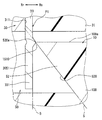
ここで図18に示すように、軸受中心線に沿うストッパ面1001aでの係止作用によって回転ストッパ1000が固定ストッパ1001に動きを止められる特定回転側Rsに対し、逆側Rrへ検出回転体1002が傾斜すると、特に問題が生じる。その問題とは、ストッパ面1001aに対する回転ストッパ1000の接触位置が、図18に二点鎖線で示す回転領域の限界回転位置Plから、特定回転側Rsの逆側Rrへとずれた回転位置Prとなるのに対応して、検出される液面レベルに検出誤差が生じることにある。この場合に液面レベルの検出範囲は、正規範囲よりも検出誤差分だけ狭くなる。これは、液面レベルの保証可能な検出範囲が狭くなることを意味するため、保証性能という点で望ましくない。
Here, as shown in FIG. 18, the
本発明は、以上説明した問題に鑑みてなされたものであって、その目的は、液面レベルの高い検出精度と保証可能な広い検出範囲とを実現する液面検出装置を、提供することにある。 The present invention has been made in view of the above-described problems, and an object of the present invention is to provide a liquid level detection device that realizes a high liquid level detection accuracy and a wide assureable detection range. is there.
以下、課題を達成するための発明の技術的手段について、説明する。尚、発明の技術的手段を開示する特許請求の範囲及び本欄に記載された括弧内の符号は、後に詳述する実施形態に記載された具体的手段との対応関係を示すものであり、発明の技術的範囲を限定するものではない。 The technical means of the invention for achieving the object will be described below. The reference numerals in parentheses described in the claims and in this section disclosing the technical means of the invention indicate the correspondence with the specific means described in the embodiment described in detail later. It is not intended to limit the technical scope of the invention.
上述の課題を解決するために開示された第一発明は、
容器(2)内に貯留された液体の液面レベル(LL)を検出する液面検出装置(1)であって、
容器に対して位置固定される固定ストッパ(52,2052,1052)を有する検出固定体(10)と、
液体に浮遊するフロート(20)と、
フロートの上下動に追従して回転可能に、検出固定体により軸受されており、回転位置に対応した液面レベルが検出される検出回転体(30)とを、備え、
検出回転体は、検出固定体側へ突出している回転ストッパ(51,3051)を有し、回転ストッパが特定回転側(Rs)への動きを固定ストッパに止められることにより回転領域(A)が規制され、
固定ストッパは、検出回転体側へ向かうほど特定回転側とは逆側(Rr)へ張出して、回転領域の限界回転位置(Pl)にて回転ストッパを係止するストッパ面(520,2520,1520)を、形成している。
The first invention disclosed in order to solve the above-mentioned problem is
A liquid level detection device (1) for detecting a liquid level (LL) of a liquid stored in a container (2),
A detection fixing body (10) having a fixing stopper (52, 2052, 1052) fixed in position relative to the container;
A float (20) floating in a liquid;
A detection rotating body (30) that is supported by a detection fixing body and is capable of rotating in accordance with the vertical movement of the float and that detects a liquid level corresponding to the rotation position;
The detection rotating body has a rotation stopper (51, 3051) protruding toward the detection fixed body, and the rotation area (A) is restricted by the rotation stopper being stopped by the fixed stopper from moving toward the specific rotation side (Rs). And
The fixed stopper protrudes to the opposite side (Rr) from the specific rotation side toward the detection rotating body side, and stopper surfaces (520, 2520, 1520) for locking the rotation stopper at the limit rotation position (Pl) of the rotation region. Is forming.
このように第一発明による検出固定体の固定ストッパでは、検出回転体側へ向かうほど特定回転側とは逆側へ張出しているストッパ面が、回転領域の限界回転位置にて回転ストッパを係止することで、特定回転側への検出回転体の動きを止める。これによれば、検出回転体が検出固定体との間の軸受けガタ等により特定回転側の逆側へ傾斜したとしても、検出回転体側ほど当該逆側へと張出したストッパ面に対する回転ストッパの接触位置は、当該逆側へのずれを低減され得る。故に、ストッパ面に対する回転ストッパの接触位置が限界回転位置よりもずれる側、即ち特定回転側の逆側となる回転位置に対応して検出の液面レベルについては、当該ずれによる検出誤差も低減され得る。したがって、液面レベルの高い検出精度と保証可能な広い検出範囲とを実現することができる。 As described above, in the fixed stopper of the detection fixed body according to the first invention, the stopper surface that protrudes toward the side opposite to the specific rotation side toward the detection rotary body side locks the rotation stopper at the limit rotation position of the rotation region. This stops the movement of the detection rotating body toward the specific rotation side. According to this, even if the detection rotator is inclined to the opposite side of the specific rotation side due to bearing play between the detection fixed body and the like, the rotation stopper contacts the stopper surface that protrudes toward the opposite side toward the detection rotator side. The position can be reduced in the reverse direction. Therefore, the detection error due to the deviation is reduced for the detected liquid level corresponding to the rotation position where the contact position of the rotation stopper with respect to the stopper surface deviates from the limit rotation position, that is, the rotation position opposite to the specific rotation side. obtain. Therefore, it is possible to realize a detection accuracy with a high liquid level and a wide detection range that can be guaranteed.
また、開示された第二発明の固定ストッパ(52,2052)においてストッパ面(520,2520)は、検出回転体側のストッパ端部(520a)により限界回転位置の回転ストッパを係止する。 Further, in the fixed stopper (52, 2052) of the disclosed second invention, the stopper surface (520, 2520) locks the rotation stopper at the limit rotation position by the stopper end (520a) on the detection rotating body side.
このように第二発明による固定ストッパでは、検出回転体側ほど特定回転側とは逆側へ張出しているストッパ面のうち、検出回転体側のストッパ端部により、限界回転位置の回転ストッパが係止されることとなる。これによれば、ストッパ端部に対する回転ストッパの接触位置を、検出回転体の傾斜がない場合の正規位置へと可及的に近づけて、当該接触位置の特定回転側とは逆側へのずれ低減作用を高め得る。故に、検出誤差を低減して、保証可能な広い検出範囲の実現に貢献することができる。 As described above, in the fixed stopper according to the second invention, the rotation stopper at the limit rotation position is locked by the stopper end portion on the detection rotor side, out of the stopper surface projecting toward the detection rotor side opposite to the specific rotation side. The Rukoto. According to this, the contact position of the rotation stopper with respect to the stopper end is brought as close as possible to the normal position when the detection rotating body is not inclined, and the contact position is shifted to the side opposite to the specific rotation side. Reduction action can be enhanced. Therefore, it is possible to reduce the detection error and contribute to the realization of a wide detection range that can be guaranteed.
以下、本発明の複数の実施形態を図面に基づいて説明する。尚、各実施形態において対応する構成要素には同一の符号を付すことにより、重複する説明を省略する場合がある。各実施形態において構成の一部分のみを説明している場合、当該構成の他の部分については、先行して説明した他の実施形態の構成を適用することができる。また、各実施形態の説明において明示している構成の組み合わせばかりではなく、特に組み合わせに支障が生じなければ、明示していなくても複数の実施形態の構成同士を部分的に組み合わせることができる。 Hereinafter, a plurality of embodiments of the present invention will be described with reference to the drawings. In addition, the overlapping description may be abbreviate | omitted by attaching | subjecting the same code | symbol to the corresponding component in each embodiment. When only a part of the configuration is described in each embodiment, the configuration of the other embodiment described above can be applied to the other part of the configuration. Moreover, not only the combination of the configurations explicitly described in the description of each embodiment, but also the configuration of a plurality of embodiments can be partially combined even if they are not explicitly described, as long as there is no problem in the combination.
(第一実施形態)
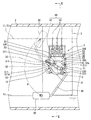
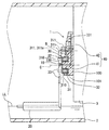
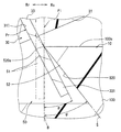
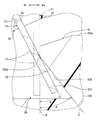
図1,2に示すように、本発明の第一実施形態による液面検出装置1は、車両における「容器」としての燃料タンク2内に、搭載される。ここで燃料タンク2は、車両の内燃機関へ供給される「液体」としての燃料を、内部に貯留する。そこで液面検出装置1は、燃料タンク2内のうち燃料に浸る位置にて燃料ポンプモジュール3等に保持された状態下、当該燃料の液面レベルLLを検出する。
(First embodiment)
As shown in FIGS. 1 and 2, the liquid
(基本構成)
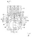
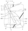
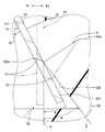
まず、液面検出装置1の基本構成を説明する。図1〜3に示すように液面検出装置1は、検出固定体10、フロート20、検出回転体30及び回転センサ40を備えている。
(Basic configuration)
First, the basic configuration of the liquid
検出固定体10は、例えばポリフェニレンサルファイド樹脂等の耐燃料性樹脂材料により形成されている。検出固定体10は、固定本体100及び固定軸受101を含んで構成されている。固定本体100は、燃料タンク2内にて上下方向に沿って配置される矩形板状を、呈している。固定本体100は、燃料ポンプモジュール3に装着されることで、当該燃料ポンプモジュール3を介して燃料タンク2内に位置固定される。図2に示すように固定軸受101は、固定本体100から検出回転体30側へ向かって突出する円柱状を、呈している。固定軸受101の中心線は、燃料タンク2内では横方向に沿って延伸することとなる軸受中心線Cとして、定義される。
The
図1,2に示すようにフロート20は、例えば発泡エボナイト等の軽量材料によりブロック状に形成されている。フロート20には、燃料よりも小さい比重が与えられている。フロート20は、燃料タンク2内にて燃料液面に浮遊することで、液面レベルLLに対応した位置へと上下動する。
As shown in FIGS. 1 and 2, the
検出回転体30は、回転本体31、一対のマグネット32及びアーム33を含んで構成されている。回転本体31は、例えばポリフェニレンサルファイド樹脂等の耐燃料性樹脂材料により円板状に形成されている。回転本体31は、固定軸受101により軸受されることで、軸受中心線Cまわりの両側に回転可能となっている。回転本体31は、軸受中心線Cを径方向に挟む両側に、それぞれ係合爪状の装着爪310を有している。さらに回転本体31は、軸受中心線Cから片方の装着爪310よりも径方向に偏心した複数箇所に、それぞれ挿入孔311を有している。各挿入孔311は、軸受中心線Cに沿って軸方向に回転本体31を貫通する円筒孔状に、形成されている。
The
図2に示すようにマグネット32は、軸受中心線Cを径方向に挟む両側に、それぞれ一つずつ設けられている。各マグネット32は、例えばフェライト磁石等の強磁性金属材料により扇形柱状に形成されている。各マグネット32は、回転本体31の内部に一体回転可能に埋設されている。各マグネット32は、固定軸受101に対して作用させる磁界を、共同して発生する。
As shown in FIG. 2, one
図1〜3に示すようにアーム33は、例えばステンレス鋼等の弾性金属材料により丸棒状に形成されている。アーム33は、回転本体31とフロート20との間を、複数箇所にて屈曲した屈曲線状に接続している。具体的にアーム33の一端部側は、フロート20に対して使用中は離脱不能に挿通されることで、当該フロート20を支持している。フロート20とは反対側となるアーム33の他端部側は、複数の挿入孔311の中で、燃料タンク2のサイズ等といった製品仕様に応じた一つに挿入される。
As shown in FIGS. 1 to 3, the
アーム33の中間部は、装着部330を形成している。装着部330は、一対の装着爪310の係合により離脱不能に保持されることで、回転本体31に対して一体回転可能に装着されている。かかる装着によりアーム33は、フロート20の上下動に追従して軸受中心線Cまわりに回転することで、液面レベルLLに対応した回転位置へと動く。このときアーム33は、装着部330にて軸受中心線Cとは実質垂直な径方向に延伸した状態を、回転本体31の任意の回転位置で維持する。
An intermediate portion of the
回転センサ40は、検出素子41及び複数のターミナル42を含んで構成されている。検出素子41は、例えばホール素子等の磁気検出素子である。検出素子41は、固定軸受101内に収容されることで、一対のマグネット32間に配置されている。検出素子41は、それらマグネット32の発生した磁界を感知する。ここで、検出素子41の感知する磁界は、回転本体31の回転位置に応じて変化する。これにより、検出素子41の出力信号に基づくことで、液面レベルLLを検出することが可能となっている。即ち、検出素子41の出力信号は、液面レベルLLの検出結果を表す信号となる。
The
ターミナル42は、複数並んで設けられ、それぞれ燃料タンク2内にて上下方向に延伸している。各ターミナル42は、例えば燐青銅といった導電性金属材料により平板帯状に形成されている。各ターミナル42は、検出素子41の対応する端子に電気接続されている。それと共に各ターミナル42は、燃料タンク2外の制御回路にも電気接続される。これらの電気接続下にて制御回路は、検出素子41の出力信号を受信することで、液面レベルLLの検出結果を認識可能となる。
A plurality of
(ストッパ構造)
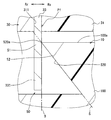
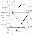
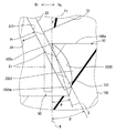
次に、液面検出装置1において検出回転体30及び検出固定体10の間に跨って構築されているストッパ構造50につき、説明する。図1,3,4に示すようにストッパ構造50は、検出回転体30の有する回転ストッパ51と、検出固定体10の有する固定ストッパ52とを、組み合わせて構成されている。
(Stopper structure)
Next, the
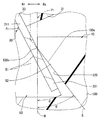
図2〜4に示すように回転ストッパ51は、アーム33の他端部として、回転本体31の挿入孔311からフロート20とは反対側へと延出している延出部331により、形成されている。ここでアーム33は、装着部330から実質直角に折曲された部分に延出部331を有している。これにより、軸受中心線Cに対して検出回転体30の傾斜しない(即ち、傾斜角度が零となる)正規位置では、延出部331の形成する回転ストッパ51が、軸受中心線Cと平行に想定される基準軸線Bに沿って、検出固定体10側へと突出した状態となる。
As shown in FIGS. 2 to 4, the
図1,3に示すように固定ストッパ52は、検出固定体10の固定本体100において検出回転体30側へ開口する凹部内面102の複数部分に、それぞれ形成されている。これにより、固定本体100の有する各固定ストッパ52は、固定本体100と一体に形成されて、燃料タンク2に対しては位置固定されている。
As shown in FIGS. 1 and 3, the fixing
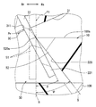
ここで、複数の挿入孔311へそれぞれアーム33が挿入されていると仮定した場合に、製品仕様に応じて制限されることとなる検出回転体30の回転領域A内には、図3に示すように回転ストッパ51の軌道Oが複数想定可能となる。そこで本実施形態では、こうして想定される各軌道O上にて回転領域Aの両端と対応する箇所に、固定ストッパ52が一つずつ配置されている。尚、これら各固定ストッパ52には、互いに実質同一の構成が与えられる。そこで以下では、図1〜3に示す特定挿入孔311(311a)へのアーム33の挿入構成下、回転領域Aのうち液面レベルLLが最上レベルLLuとなる限界回転位置Plと対応した箇所に配置の固定ストッパ52(52a)につき、代表して詳細に説明する。
Here, when it is assumed that the
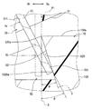
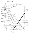
図3に示すように固定ストッパ52は、対応する軌道O上にストッパ面520を形成している。図4に示すようにストッパ面520は、検出回転体30側へ向かうほど、回転ストッパ51の特定回転側(図1,3にて時計回りとなる側)Rsとは逆側Rrへと向かって、張出している。ストッパ面520のうち検出回転体30側のストッパ端部520aは、固定本体100のうち検出回転体30側の板面100a上にて、特定回転側Rsとは逆側Rrへと最も張出している。これによりストッパ端部520aは、検出回転体30に傾きがない正規位置での回転ストッパ51の限界回転位置Plと対応した箇所に、配置されている。
As shown in FIG. 3, the fixed
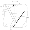
ここで軸受中心線Cに平行な基準軸線Bに対して、図4,5に示すように、検出回転体30側へ向かうほど特定回転側Rsとは逆側Rrへ傾斜する姿勢に傾斜面Sを想定し、これを仮想傾斜面Sとして定義する。かかる定義下にてストッパ面520は、仮想傾斜面S上に重なって設けられることで、当該仮想傾斜面Sの通る箇所にストッパ端部520aを位置させている。これによりストッパ面520は、仮想傾斜面Sを特定回転側Rsの逆側Rrへは越えない範囲で張出していることで、限界回転位置Plの回転ストッパ51をストッパ端部520aにより係止可能となっている。こうした係止の結果、限界回転位置Plにて回転ストッパ51が特定回転側Rsへの動きを固定ストッパ52により止められることで、当該回転ストッパ51を含む検出回転体30の回転領域Aが規制されることとなる。
Here, as shown in FIGS. 4 and 5, with respect to the reference axis B parallel to the bearing center line C, the inclined surface S is inclined toward the opposite side Rr from the specific rotation side Rs toward the
またここで図2に示すように、回転本体31が検出固定体10の固定軸受101によって軸受されている検出回転体30には、それら要素31,101間の軸受ガタに起因して、軸受中心線Cに対する傾斜が不可避的に許容されている。さらに、回転ストッパ51を形成しているアーム33の装着部330が回転本体31に装着されてなる検出回転体30には、それら要素330,31間の装着ガタに起因して、軸受中心線Cに対する傾斜が不可避的に許容されている。そこで、こうした軸受ガタ及び装着ガタ等に起因して検出回転体30に許容されている傾斜のうち、軸受中心線Cに対して特定回転側Rsとは逆側Rrへの傾斜角度が図5の如く最大値θとなる傾斜を想定し、それを最大傾斜角度θとして定義する。かかる定義下にてストッパ面520と重なる仮想傾斜面Sは、図5に示すように、検出回転体30に許容された最大傾斜角度θよりも大きな傾斜角度ψをもって、基準軸線Bから傾斜した姿勢となる。これにより、限界回転位置Plにて回転ストッパ51は、ストッパ面520のうちストッパ端部520aに限定して接触することが、可能となっている。尚、傾斜角度θ,ψについて図5では、それぞれは説明の理解を容易にするために実際よりも大きく図示されているが、大小関係は図示の通りである。
In addition, as shown in FIG. 2, the
(作用効果)
以上説明した第一実施形態の作用効果を、以下に説明する。
(Function and effect)
The effects of the first embodiment described above will be described below.
第一実施形態による検出固定体10の固定ストッパ52では、検出回転体30側へ向かうほど特定回転側Rsとは逆側Rrへ張出しているストッパ面520が、回転領域Aの限界回転位置Plにて回転ストッパ51を係止することで、特定回転側Rsへの検出回転体30の動きを止める。これによれば、検出回転体30が検出固定体10との間の軸受けガタ等により特定回転側Rsとは逆側Rrへ傾斜したとしても、検出回転体30側ほど当該逆側Rrへと張出したストッパ面520に対する回転ストッパ51の接触位置は、当該逆Rr側へのずれを低減され得る(図5,18を対比参照)。故に、ストッパ面520に対する回転ストッパ51の接触位置が限界回転位置Plよりもずれる側、即ち特定回転側Rsの逆側Rrとなる図5の回転位置Prに対応して検出の液面レベルLLについては、当該ずれによる検出誤差も低減され得る。したがって、液面レベルLLの高い検出精度と保証可能な広い検出範囲とを実現することができる。
In the fixed
また、第一実施形態による固定ストッパ52では、検出回転体30側ほど特定回転側Rsとは逆側Rrへ張出しているストッパ面520のうち、検出回転体30側のストッパ端部520aにより、限界回転位置Plの回転ストッパ51が係止されることとなる。これによれば、ストッパ端部520aに対する回転ストッパ51の接触位置を、検出回転体30の傾斜がない場合の正規位置(図5の二点鎖線参照)へと可及的に近づけて、当該接触位置の特定回転側Rsとは逆側Rrへのずれ低減作用を高め得る。故に、検出誤差を低減して、保証可能な広い検出範囲の実現に貢献することができる。
Further, in the fixed
さらに第一実施形態によると、正規位置では軸受中心線Cと平行な基準軸線Bに沿って回転ストッパ51が検出固定体10側へと突出している検出回転体30は、特定回転側Rsとは逆側Rrへの最大傾斜角度θまでの傾斜を、軸受中心線Cに対して許容されている。ここで、検出回転体30側へ向かうほど基準軸線Bに対して逆側Rrへと最大傾斜角度θより大きく傾斜し且つストッパ端部520aを通る姿勢に、仮想傾斜面Sが想定されることで、ストッパ面520の張出範囲は、当該仮想傾斜面Sを逆側Rrへ越えない構成となる。こうした構成によれば、最大傾斜角度θまで傾斜した検出回転体30の回転ストッパ51であっても、それより大きな傾斜となる仮想傾斜面Sを特定回転側Rsの逆側Rrへは越えていないストッパ面520に対しては、検出回転体30側のストッパ端部520aにて正しく接触し得る。故に、ストッパ端部520aに対する回転ストッパ51の接触位置につき、特定回転側Rsとは逆側Rrへのずれ低減作用を確実に高め得る。したがって、検出誤差の低減効果、ひいては保証可能な広い検出範囲の実現効果を、確固たる効果として発揮することができる。
Furthermore, according to the first embodiment, the
またさらに第一実施形態の検出回転体30では、検出固定体10により軸受されている回転本体31が、フロート20との間をアーム33により接続されている。ここで特にアーム33によると、回転本体31と一体回転可能に装着されている装着部330よりもフロート20とは反対側へ延出している延出部331が、回転ストッパ51を形成している。こうした構成によれば、回転本体31及び検出固定体10間の軸受けガタだけでなく、回転本体31及び装着部330間の装着ガタに起因して、延出部331の形成する回転ストッパ51を有した検出回転体30の傾斜が想定され得る。しかし、検出回転体30側ほど特定回転側Rsの逆側Rrへと張出しているストッパ面520に対して、そうした回転ストッパ51が接触することによれば、当該逆側Rrへの接触位置のずれが低減され得る。故に、検出誤差の低減効果、ひいては保証可能な広い検出範囲の実現効果を、軸受けガタや装着ガタに拘わらず発揮することができる。
Furthermore, in the
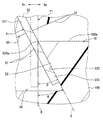
(第二実施形態)
図6に示すように本発明の第二実施形態は、第一実施形態の変形例である。
(Second embodiment)
As shown in FIG. 6, the second embodiment of the present invention is a modification of the first embodiment.
第二実施形態による固定ストッパ2052のストッパ面2520は、検出回転体30側のストッパ端部520aを通る仮想傾斜面Sよりも特定回転側Rsへと凹んだ凹面状に、形成されている。ここで特にストッパ面2520は、検出回転体30側へ単位長さ向かうほど特定回転側Rsの逆側Rrへと張出する張出長さの割合を張出変化率として、当該張出変化率が検出回転体30側ほど増大するように湾曲した湾曲凹面状を、呈している。
The
このような第二実施形態の固定ストッパ2052では、特定回転側Rsへと凹む凹面状ストッパ面2520が、ストッパ端部520aにて限界回転位置Plの回転ストッパ51を正しく係止することとなる。これによれば、ストッパ面2520のうちストッパ端部520aを狙って回転ストッパ51を接触させ易くなるので、当該接触位置での特定回転側Rsとは逆側Rrへのずれ低減作用を確実に高め得る。故に、検出誤差の低減効果、ひいては保証可能な広い検出範囲の実現効果を、確固たる効果として発揮することができる。
In such a fixed
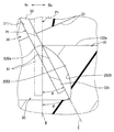
(第三実施形態)
図7に示すように本発明の第三実施形態は、第一実施形態の変形例である。
(Third embodiment)
As shown in FIG. 7, the third embodiment of the present invention is a modification of the first embodiment.
第三実施形態による回転ストッパ3051は、限界回転位置Plにて検出回転体30側のストッパ端部520aにより係止可能となる箇所に、円環板状のストッパ突起3510を有している。ストッパ突起3510は、アーム33の延出部331に対して別体に形成されて、同軸上に装着されている。これにより、特定挿入孔311へのアーム33の挿入構成下、軌道Oの両端に対応した二箇所の固定ストッパ52に対しては、それぞれの特定回転側Rs(即ち、相反する側)へ突出している。
The
このような第三実施形態の回転ストッパ3051では、ストッパ面520のストッパ端部520aにより限界回転位置Plにて係止されるストッパ突起3510が、特定回転側Rsへ突出した状態となる。これによれば、ストッパ面520のうちストッパ端部520aを狙ってストッパ突起3510を接触させ得るので、当該接触位置での特定回転側Rsとは逆側Rrへのずれ低減作用を確実に高め得る。故に、検出誤差の低減効果、ひいては保証可能な広い検出範囲の実現効果を、確固たる効果として発揮することができる。
In such a
(他の実施形態)
以上、本発明の複数の実施形態について説明したが、本発明は、それらの実施形態に限定して解釈されるものではなく、本発明の要旨を逸脱しない範囲内において種々の実施形態及び組み合わせに適用することができる。
(Other embodiments)
Although a plurality of embodiments of the present invention have been described above, the present invention is not construed as being limited to these embodiments, and various embodiments and combinations can be made without departing from the scope of the present invention. Can be applied.
具体的に、第一〜第三実施形態に関する変形例1では、図8,9,10(図8,9,10はいずれも第一実施形態の変形例)に示すように、固定本体100の板面100aから検出回転体30とは反対側へずれた箇所にて、ストッパ面520,2520のストッパ端部520aが張出していてもよい。
Specifically, in
第一〜第三実施形態に関する変形例2では、図11(図11は第一実施形態の変形例)に示すように、固定本体100に対して固定ストッパ52,2052が、別体に形成されて装着されていてもよい。第三実施形態に関する変形例3では、ストッパ突起3510がアーム33と一体に形成されていてもよい。
In
第一〜第三実施形態に関する変形例4では、図12,13(図12,13はそれぞれ第一及び第二実施形態の変形例)に示すように、ストッパ端部520aを通ってストッパ面520,2520を特定回転側Rsの逆側Rrへは越えさせない仮想傾斜面Sにつき、検出回転体30に許容された最大傾斜角度θよりも小さな傾斜角度ψをもって想定されてもよい。ここで図12,13の変形例4では、正規位置の回転ストッパ51がストッパ面520と接触する接触箇所1520aに、限界回転位置Plと対応した箇所が設定されている。これによりストッパ面520は、特定回転側Rsの逆側Rrへと傾斜した検出回転体30における回転ストッパ51に対して、ストッパ端部520aから離れた箇所1520aにて接触する。
In the fourth modification regarding the first to third embodiments, as shown in FIGS. 12 and 13 (FIGS. 12 and 13 are modifications of the first and second embodiments, respectively), the
第一〜第三実施形態に関する変形例5では、図14,15(図14,15はそれぞれ第一及び第二実施形態の変形例)に示すように、ストッパ端部520aを通ってストッパ面520,2520を特定回転側Rsの逆側Rrへは越えさせない仮想傾斜面Sにつき、検出回転体30に許容された最大傾斜角度θと実質同一の傾斜角度ψに想定されてもよい。
In the fifth modification relating to the first to third embodiments, as shown in FIGS. 14 and 15 (FIGS. 14 and 15 are modifications of the first and second embodiments, respectively), the
第一及び第三実施形態に関する変形例6では、図16(図16は第一実施形態の変形例)に示すように、仮想傾斜面Sを越えて特定回転側Rsの逆側Rrへと膨らんだ凸面状に、固定ストッパ1052のストッパ面1520が形成されていてもよい。ここで図16の変形例6では、検出回転体30側へ単位長さ向かうほど特定回転側Rsの逆側Rrへと張出する張出長さの割合を張出変化率として、当該張出変化率が検出回転体30側ほど減少するように湾曲した湾曲凸面状に、ストッパ面1520が形成されている。また、図16の変形例6では、正規位置の回転ストッパ51が凸面状のストッパ面1520と接触する接触箇所1520aに、限界回転位置Plと対応した箇所が設定されている。これによりストッパ面1520は、特定回転側Rsの逆側Rrへと傾斜した検出回転体30における回転ストッパ51に対して、ストッパ端部520aから離れた箇所1520aにて接触する。
In the sixth modified example relating to the first and third embodiments, as shown in FIG. 16 (FIG. 16 is a modified example of the first embodiment), it swells over the virtual inclined surface S to the reverse side Rr of the specific rotation side Rs. A
第一〜第三実施形態に関する変形例7では、回転ストッパ51,3051の軌道O上にて回転領域Aの片側の限界回転位置Plと対応した箇所にのみ、固定ストッパ52,2052が設けられていてもよい。この場合、上述した変形例3のうち第三実施形態に関するものとして、図17に示すように、アーム33の一部を屈曲させて特定回転側Rsへと突出させることで、ストッパ突起1510が形成されていてもよい。
In the modified example 7 related to the first to third embodiments, the fixed
第一〜第三実施形態に関する変形例8では、挿入孔311が一つだけ設けられて、回転ストッパ51,3051の単一の軌道O上に、固定ストッパ52,2052が設けられていてもよい。第一〜第三実施形態に関する変形例9では、アーム33の延出部331に代えて、回転本体31の一部が突出してなる突部により、回転ストッパ51が形成されていてもよい。第一〜第三実施形態に関する変形例10では、燃料以外の液面を貯留する「容器」内に液面検出装置1が搭載されて、液面レベルLLを検出してもよい。
In the modification 8 regarding the first to third embodiments, only one
1 液面検出装置、2 燃料タンク、10 検出固定体、20 フロート、30 検出回転体、31 回転本体、33 アーム、40 回転センサ、50 ストッパ構造、51,3051 回転ストッパ、52,52a,2052,1052 固定ストッパ、100 固定本体、101 固定軸受、311,311a 挿入孔、330 装着部、331 延出部、520,2520,1520 ストッパ面、520a ストッパ端部、3510,1510 ストッパ突起、A 回転領域、C 軸受中心線、LL 液面レベル、LLu 最上レベル、O 軌道、Pl 限界回転位置、Rs 特定回転側、Rr 逆側、S 仮想傾斜面、θ 最大傾斜角度、ψ 傾斜角度
DESCRIPTION OF
Claims (6)
前記容器に対して位置固定される固定ストッパ(52,2052,1052)を有する検出固定体(10)と、
前記液体に浮遊するフロート(20)と、
前記フロートの上下動に追従して回転可能に、前記検出固定体により軸受されており、回転位置に対応した前記液面レベルが検出される検出回転体(30)とを、備え、
前記検出回転体は、前記検出固定体側へ突出している回転ストッパ(51,3051)を有し、前記回転ストッパが特定回転側(Rs)への動きを前記固定ストッパに止められることにより回転領域(A)が規制され、
前記固定ストッパは、前記検出回転体側へ向かうほど前記特定回転側とは逆側(Rr)へ張出して、前記回転領域の限界回転位置(Pl)にて前記回転ストッパを係止するストッパ面(520,2520,1520)を、形成している液面検出装置。 A liquid level detection device (1) for detecting a liquid level (LL) of a liquid stored in a container (2),
A detection fixing body (10) having a fixing stopper (52, 2052, 1052) fixed to the container;
A float (20) floating in the liquid;
A detection rotating body (30) that is supported by the detection fixed body so as to be able to rotate following the vertical movement of the float and that detects the liquid level corresponding to the rotation position;
The detection rotating body has rotation stoppers (51, 3051) protruding toward the detection fixed body side, and the rotation stopper (51) moves to a specific rotation side (Rs) by the fixed stopper to stop the rotation region ( A) is regulated,
The fixed stopper protrudes to the opposite side (Rr) to the specific rotation side as it goes to the detection rotating body side, and a stopper surface (520) that locks the rotation stopper at the limit rotation position (Pl) of the rotation region. , 2520, 1520).
前記回転ストッパは、前記軸受中心線に対して前記検出回転体の傾斜しない正規位置では、前記軸受中心線と平行に想定される基準軸線(B)に沿って、前記検出固定体側へ突出しており、
前記検出回転体側へ向かうほど前記基準軸線に対して前記逆側へ前記最大傾斜角度よりも大きく傾斜し且つ前記ストッパ端部を通る姿勢に想定される傾斜面を、仮想傾斜面(S)と定義すると、前記ストッパ面は、前記仮想傾斜面を前記逆側へ越えない範囲で張出している請求項2に記載の液面検出装置。 The detection rotating body is allowed to tilt up to the maximum tilt angle (θ) to the opposite side with respect to the bearing center line (C) of the detection rotating body by the detection fixed body,
The rotation stopper protrudes toward the detection fixed body along a reference axis (B) assumed to be parallel to the bearing center line at a normal position where the detection rotation body is not inclined with respect to the bearing center line. ,
A hypothetical inclined surface (S) is defined as an inclined surface that is assumed to be inclined to be larger than the maximum inclination angle toward the opposite side with respect to the reference axis as it goes toward the detection rotating body, and passes through the stopper end. Then, the said stopper surface is a liquid level detection apparatus of Claim 2 which protrudes in the range which does not exceed the said virtual inclined surface to the said reverse side.
前記検出固定体により軸受されている回転本体(31)と、
前記回転本体と前記フロートとの間を接続しているアーム(33)とを、含んで構成され、
前記アームは、
前記回転本体と一体回転可能に装着されている装着部(330)と、
前記装着部よりも前記フロートとは反対側へ延出して、前記回転ストッパ(51,3051)を形成している延出部(331)とを、有する請求項1〜5のいずれか一項に記載の液面検出装置。 The detection rotor is
A rotating body (31) that is supported by the detection stationary body;
An arm (33) connecting between the rotating body and the float,
The arm is
A mounting portion (330) mounted to be rotatable integrally with the rotating body;
The extension part (331) which extends to the opposite side to the float from the mounting part, and forms the rotation stopper (51, 3051), has any one of claims 1-5. The liquid level detection apparatus described.
Priority Applications (1)
| Application Number | Priority Date | Filing Date | Title |
|---|---|---|---|
| JP2016138858A JP6642312B2 (en) | 2016-07-13 | 2016-07-13 | Liquid level detector |
Applications Claiming Priority (1)
| Application Number | Priority Date | Filing Date | Title |
|---|---|---|---|
| JP2016138858A JP6642312B2 (en) | 2016-07-13 | 2016-07-13 | Liquid level detector |
Publications (2)
| Publication Number | Publication Date |
|---|---|
| JP2018009880A true JP2018009880A (en) | 2018-01-18 |
| JP6642312B2 JP6642312B2 (en) | 2020-02-05 |
Family
ID=60995398
Family Applications (1)
| Application Number | Title | Priority Date | Filing Date |
|---|---|---|---|
| JP2016138858A Expired - Fee Related JP6642312B2 (en) | 2016-07-13 | 2016-07-13 | Liquid level detector |
Country Status (1)
| Country | Link |
|---|---|
| JP (1) | JP6642312B2 (en) |
-
2016
- 2016-07-13 JP JP2016138858A patent/JP6642312B2/en not_active Expired - Fee Related
Also Published As
| Publication number | Publication date |
|---|---|
| JP6642312B2 (en) | 2020-02-05 |
Similar Documents
| Publication | Publication Date | Title |
|---|---|---|
| JP5983494B2 (en) | Liquid level detector | |
| US10704950B2 (en) | Liquid level detecting device | |
| JP6123521B2 (en) | Liquid level detector | |
| US10712193B2 (en) | Liquid level detecting device | |
| EP1308692A1 (en) | Rotation angle sensor | |
| US6386020B1 (en) | Rotary sensor capable of high-precision detection of rotation angle transmitted from outside | |
| JP6642312B2 (en) | Liquid level detector | |
| JP4732700B2 (en) | Magnetically passive position sensor and method for manufacturing a magnetically passive position sensor | |
| US10697819B2 (en) | Liquid level detecting device with arm fixing portion having holding groove for receiving float arm | |
| JP2024130898A (en) | Angle detection device | |
| CN107110665A (en) | Rotation angle detection apparatus and the rotation angle detecting unit using the rotation angle detection apparatus | |
| JP5230517B2 (en) | Position detection device | |
| JP6344222B2 (en) | Liquid level detector | |
| JPS62237357A (en) | Rotary sensor | |
| JP6842454B2 (en) | Liquid level detector | |
| JP7015096B2 (en) | Liquid level detector | |
| JP5019044B2 (en) | Liquid level detector | |
| JP2010139490A (en) | Liquid level sensor | |
| JP2010090769A (en) | Shaft support structure and rotary sensor | |
| JP6344226B2 (en) | Liquid level detector | |
| JP2020187025A (en) | Rotation angle detector | |
| JP7157114B2 (en) | Liquid level detector | |
| JP2000162022A (en) | Liquid level detector | |
| US9021871B2 (en) | Fuel amount detection device for vehicle | |
| JP6558321B2 (en) | Liquid level detector |
Legal Events
| Date | Code | Title | Description |
|---|---|---|---|
| A621 | Written request for application examination |
Free format text: JAPANESE INTERMEDIATE CODE: A621 Effective date: 20181001 |
|
| TRDD | Decision of grant or rejection written | ||
| A01 | Written decision to grant a patent or to grant a registration (utility model) |
Free format text: JAPANESE INTERMEDIATE CODE: A01 Effective date: 20191203 |
|
| A61 | First payment of annual fees (during grant procedure) |
Free format text: JAPANESE INTERMEDIATE CODE: A61 Effective date: 20191216 |
|
| R151 | Written notification of patent or utility model registration |
Ref document number: 6642312 Country of ref document: JP Free format text: JAPANESE INTERMEDIATE CODE: R151 |
|
| LAPS | Cancellation because of no payment of annual fees |