JP2018009869A - Tire mount sensor and road surface state estimation device including the same - Google Patents
Tire mount sensor and road surface state estimation device including the same Download PDFInfo
- Publication number
- JP2018009869A JP2018009869A JP2016138653A JP2016138653A JP2018009869A JP 2018009869 A JP2018009869 A JP 2018009869A JP 2016138653 A JP2016138653 A JP 2016138653A JP 2016138653 A JP2016138653 A JP 2016138653A JP 2018009869 A JP2018009869 A JP 2018009869A
- Authority
- JP
- Japan
- Prior art keywords
- road surface
- tire
- acceleration
- detection signal
- acceleration sensor
- Prior art date
- Legal status (The legal status is an assumption and is not a legal conclusion. Google has not performed a legal analysis and makes no representation as to the accuracy of the status listed.)
- Granted
Links
Images
Classifications
-
- B—PERFORMING OPERATIONS; TRANSPORTING
- B60—VEHICLES IN GENERAL
- B60W—CONJOINT CONTROL OF VEHICLE SUB-UNITS OF DIFFERENT TYPE OR DIFFERENT FUNCTION; CONTROL SYSTEMS SPECIALLY ADAPTED FOR HYBRID VEHICLES; ROAD VEHICLE DRIVE CONTROL SYSTEMS FOR PURPOSES NOT RELATED TO THE CONTROL OF A PARTICULAR SUB-UNIT
- B60W40/00—Estimation or calculation of non-directly measurable driving parameters for road vehicle drive control systems not related to the control of a particular sub unit, e.g. by using mathematical models
- B60W40/02—Estimation or calculation of non-directly measurable driving parameters for road vehicle drive control systems not related to the control of a particular sub unit, e.g. by using mathematical models related to ambient conditions
- B60W40/06—Road conditions
-
- B—PERFORMING OPERATIONS; TRANSPORTING
- B60—VEHICLES IN GENERAL
- B60C—VEHICLE TYRES; TYRE INFLATION; TYRE CHANGING; CONNECTING VALVES TO INFLATABLE ELASTIC BODIES IN GENERAL; DEVICES OR ARRANGEMENTS RELATED TO TYRES
- B60C19/00—Tyre parts or constructions not otherwise provided for
-
- B—PERFORMING OPERATIONS; TRANSPORTING
- B60—VEHICLES IN GENERAL
- B60C—VEHICLE TYRES; TYRE INFLATION; TYRE CHANGING; CONNECTING VALVES TO INFLATABLE ELASTIC BODIES IN GENERAL; DEVICES OR ARRANGEMENTS RELATED TO TYRES
- B60C99/00—Subject matter not provided for in other groups of this subclass
-
- G—PHYSICS
- G01—MEASURING; TESTING
- G01H—MEASUREMENT OF MECHANICAL VIBRATIONS OR ULTRASONIC, SONIC OR INFRASONIC WAVES
- G01H1/00—Measuring characteristics of vibrations in solids by using direct conduction to the detector
-
- G—PHYSICS
- G01—MEASURING; TESTING
- G01H—MEASUREMENT OF MECHANICAL VIBRATIONS OR ULTRASONIC, SONIC OR INFRASONIC WAVES
- G01H1/00—Measuring characteristics of vibrations in solids by using direct conduction to the detector
- G01H1/003—Measuring characteristics of vibrations in solids by using direct conduction to the detector of rotating machines
-
- G—PHYSICS
- G01—MEASURING; TESTING
- G01K—MEASURING TEMPERATURE; MEASURING QUANTITY OF HEAT; THERMALLY-SENSITIVE ELEMENTS NOT OTHERWISE PROVIDED FOR
- G01K13/00—Thermometers specially adapted for specific purposes
-
- G—PHYSICS
- G01—MEASURING; TESTING
- G01W—METEOROLOGY
- G01W1/00—Meteorology
-
- B—PERFORMING OPERATIONS; TRANSPORTING
- B60—VEHICLES IN GENERAL
- B60C—VEHICLE TYRES; TYRE INFLATION; TYRE CHANGING; CONNECTING VALVES TO INFLATABLE ELASTIC BODIES IN GENERAL; DEVICES OR ARRANGEMENTS RELATED TO TYRES
- B60C19/00—Tyre parts or constructions not otherwise provided for
- B60C2019/004—Tyre sensors other than for detecting tyre pressure
-
- B—PERFORMING OPERATIONS; TRANSPORTING
- B60—VEHICLES IN GENERAL
- B60W—CONJOINT CONTROL OF VEHICLE SUB-UNITS OF DIFFERENT TYPE OR DIFFERENT FUNCTION; CONTROL SYSTEMS SPECIALLY ADAPTED FOR HYBRID VEHICLES; ROAD VEHICLE DRIVE CONTROL SYSTEMS FOR PURPOSES NOT RELATED TO THE CONTROL OF A PARTICULAR SUB-UNIT
- B60W2400/00—Indexing codes relating to detected, measured or calculated conditions or factors
-
- B—PERFORMING OPERATIONS; TRANSPORTING
- B60—VEHICLES IN GENERAL
- B60W—CONJOINT CONTROL OF VEHICLE SUB-UNITS OF DIFFERENT TYPE OR DIFFERENT FUNCTION; CONTROL SYSTEMS SPECIALLY ADAPTED FOR HYBRID VEHICLES; ROAD VEHICLE DRIVE CONTROL SYSTEMS FOR PURPOSES NOT RELATED TO THE CONTROL OF A PARTICULAR SUB-UNIT
- B60W2552/00—Input parameters relating to infrastructure
-
- G—PHYSICS
- G01—MEASURING; TESTING
- G01K—MEASURING TEMPERATURE; MEASURING QUANTITY OF HEAT; THERMALLY-SENSITIVE ELEMENTS NOT OTHERWISE PROVIDED FOR
- G01K2205/00—Application of thermometers in motors, e.g. of a vehicle
Landscapes
- Engineering & Computer Science (AREA)
- Physics & Mathematics (AREA)
- General Physics & Mathematics (AREA)
- Mechanical Engineering (AREA)
- Transportation (AREA)
- Automation & Control Theory (AREA)
- Mathematical Physics (AREA)
- Environmental & Geological Engineering (AREA)
- Ecology (AREA)
- Environmental Sciences (AREA)
- Biodiversity & Conservation Biology (AREA)
- Atmospheric Sciences (AREA)
- Life Sciences & Earth Sciences (AREA)
- Tires In General (AREA)
- Measurement Of Mechanical Vibrations Or Ultrasonic Waves (AREA)
- Control Of Driving Devices And Active Controlling Of Vehicle (AREA)
Abstract
【課題】的確に接地区間を検出することができるタイヤマウントセンサおよびそれを含む路面状態推定装置を提供する。
【解決手段】タイヤ3の回転角度に基づいて接地角度になる期間にのみ第1加速度センサの検出信号に基づく接地区間の抽出を行うようにする。これにより、第1加速度センサの検出信号に路面の凹凸に基づく振動のノイズが重畳されていても、接地区間を誤判定してしまうことを抑制できる。よって、凹凸の大きな走行路面であっても接地区間を誤判定することを抑制することが可能となる。
【選択図】図1A tire mount sensor capable of accurately detecting a contact section and a road surface state estimation device including the tire mount sensor are provided.
A ground contact section is extracted based on a detection signal of a first acceleration sensor only during a period when the ground contact angle is reached based on a rotation angle of a tire. Thereby, even if the noise of the vibration based on the unevenness | corrugation of a road surface is superimposed on the detection signal of a 1st acceleration sensor, it can suppress making an erroneous determination of a grounding area. Therefore, it is possible to suppress erroneous determination of the contact section even on a traveling road surface with large unevenness.
[Selection] Figure 1
Description
本発明は、タイヤが受ける振動を検出し、振動データとして車体側システムに伝えるタイヤマウントセンサおよびその振動データに基づいて路面状態を推定する路面状態推定装置に関するものである。 The present invention relates to a tire mount sensor that detects vibration received by a tire and transmits the vibration data to a vehicle body system and a road surface state estimation device that estimates a road surface state based on the vibration data.
従来、特許文献1において、タイヤトレッドの裏面にタイヤマウントセンサを備え、タイヤマウントセンサにてタイヤに加えられる振動を検出すると共に、その振動の検出結果を車体側システムに伝え、路面状態の推定を行う路面状態推定装置が提案されている。この路面状態推定装置では、タイヤマウントセンサに備えられる振動検出部の検出信号に基づいて路面状態を推定している。具体的には、路面状態に応じて振動検出部の検出信号における高周波成分のレベルが変わる。このため、タイヤトレッドのうちタイヤマウントセンサの配置箇所と対応する部分が路面に接地しているときを接地区間中として、接地区間中の振動検出部の検出信号における高周波成分のレベルを、路面状態を示す路面データとして用いる。そして、タイヤが1回転する毎にタイヤマウントセンサから車体側システムに向けて路面データを送信し、車体側システムにおいて路面データに基づいて路面状態を推定している。より詳しくは、電圧値として示される検出信号の高周波成分を積分した積分電圧値を路面データとして用い、車体側システムにおいて、積分電圧値の大きさに基づいて路面摩擦係数(以下、路面μという)の推定などを行っている。
Conventionally, in
上記のような路面状態推定装置では、接地区間中における振動に基づいて路面μの推定などを行っているが、砂利道のように大きな凹凸がある走行路面の場合、路面の凹凸形状による振動がノイズとして重畳され、接地区間中の振動のみを取得することが難しい。このため、路面μの推定などを的確に行うことができないという問題が発生する。 In the road surface state estimation device as described above, the road surface μ is estimated based on the vibration in the ground contact section, but in the case of a traveling road surface having large unevenness such as a gravel road, vibration due to the uneven shape of the road surface is generated. It is superimposed as noise and it is difficult to acquire only the vibration during the ground contact section. For this reason, there arises a problem that the estimation of the road surface μ cannot be performed accurately.
本発明は上記点に鑑みて、的確に接地区間を検出することができるタイヤマウントセンサおよびそれを含む路面状態推定装置を提供することを目的とする。 An object of this invention is to provide the tire mount sensor which can detect a contact area accurately, and a road surface state estimation apparatus including the same in view of the said point.
上記目的を達成するため、請求項1に記載のタイヤマウントセンサでは、タイヤの振動の大きさに応じた検出信号を出力する振動検出部(11a)と、タイヤの径方向の加速度に応じた検出信号を出力する加速度センサ(11b)と、加速度センサの検出信号に基づいて、タイヤの回転角度が、該タイヤの1回転中におけるトレッドのうちの振動検出部の配置箇所と対応する部分が接地する接地角度になることを検出し、該接地角度となる期間を含む測定期間を設定すると共に、該測定期間中に、振動検出部の検出信号から配置箇所と対応する部分が接地している接地区間を抽出し、該接地区間中における振動検出部の検出信号に基づいて路面状態が表された路面データを生成する信号処理部(13)と、路面データを送信する送信部(14)と、を有している。
In order to achieve the above object, in the tire mount sensor according to
このように、タイヤの回転角度に基づいて接地角度になる期間にのみ振動検出部の検出信号に基づく接地区間の抽出を行うようにしている。このため、振動検出部の検出信号に路面の凹凸に基づく振動のノイズが重畳されていても、接地区間を誤判定してしまうことを抑制できる。よって、凹凸の大きな走行路面であっても接地区間を誤判定することを抑制することが可能となる。 As described above, the contact section is extracted based on the detection signal of the vibration detection unit only during the period when the contact angle is reached based on the rotation angle of the tire. For this reason, even if the noise of the vibration based on the unevenness of the road surface is superimposed on the detection signal of the vibration detection unit, it is possible to suppress erroneous determination of the ground contact section. Therefore, it is possible to suppress erroneous determination of the contact section even on a traveling road surface with large unevenness.
なお、上記各手段の括弧内の符号は、後述する実施形態に記載の具体的手段との対応関係の一例を示すものである。 In addition, the code | symbol in the bracket | parenthesis of each said means shows an example of a corresponding relationship with the specific means as described in embodiment mentioned later.
以下、本発明の実施形態について図に基づいて説明する。なお、以下の各実施形態相互において、互いに同一もしくは均等である部分には、同一符号を付して説明を行う。 Hereinafter, embodiments of the present invention will be described with reference to the drawings. In the following embodiments, parts that are the same or equivalent to each other will be described with the same reference numerals.
(第1実施形態)
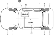
図1〜図8を参照して、本実施形態にかかるタイヤマウントセンサ1を用いた路面状態推定装置100について説明する。本実施形態にかかる路面状態推定装置100は、車両の各車輪に備えられるタイヤの接地面に加わる振動に基づいて走行中の路面状態を推定するものである。
(First embodiment)
With reference to FIGS. 1-8, the road surface
図1および図2に示すように路面状態推定装置100は、車輪側に設けられたタイヤマウントセンサ1と、車体側に備えられた各部を含む車体側システム2とを有する構成とされている。車体側システム2としては、受信機21や報知装置22などが備えられている。
As shown in FIGS. 1 and 2, the road surface
路面状態推定装置100は、タイヤマウントセンサ1よりタイヤ3と走行中の路面との間の路面μを示すデータなどの走行中の路面状態を表すデータを送信する。以下、路面μのデータのことをμデータといい、μデータなどの路面状態を表すデータのことを路面データという。
The road surface
本実施形態の場合、路面状態推定装置100は、受信機21にてタイヤマウントセンサ1から送信された路面データを受信し、路面データに示される路面状態を報知装置22より伝えている。これにより、例えば路面μが低いことや乾燥路やウェット路もしくは凍結路であることなど、路面状態をドライバに伝えることが可能となり、滑り易い路面である場合にはドライバに警告することも可能となる。具体的には、タイヤマウントセンサ1および受信機21は、以下のように構成されている。
In the case of the present embodiment, the road surface
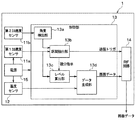
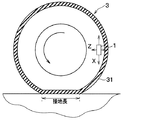
タイヤマウントセンサ1は、図2に示すように、第1加速度センサ11a、第2加速度センサ11b、温度センサ12、制御部13、RF回路14および電源15を備えた構成とされ、図3に示されるように、タイヤ3のトレッド31の裏面側に設けられる。
As shown in FIG. 2, the
第1加速度センサ11aは、タイヤに加わる振動を検出するための振動検出部を構成するものである。例えば、第1加速度センサ11aは、タイヤ3が回転する際にタイヤマウントセンサ1が描く円軌道に対して接する方向、つまり図3中の矢印Xで示すタイヤ接線方向の振動に応じた検出信号として、加速度の検出信号を出力する。
The 1st acceleration sensor 11a comprises the vibration detection part for detecting the vibration added to a tire. For example, the first acceleration sensor 11a is a detection signal corresponding to the vibration in the tire tangential direction indicated by the arrow X in FIG. 3 in the direction in contact with the circular orbit drawn by the
第2加速度センサ11bは、タイヤの回転角度を検出するために用いられる。例えば、第2加速度センサ11bは、タイヤ3の遠心方向、つまり図3中の矢印Zで示すタイヤ径方向の加速度に応じた検出信号を出力する。
The
温度センサ12は、温度に応じた検出信号を出力するもので、タイヤ3のうちのタイヤマウントセンサ1の取り付け位置の温度を検出することで、走行路面の温度を測定している。
The
制御部13は、信号処理部に相当する部分であり、第1加速度センサ11aの検出信号をタイヤ接線方向の振動データを表す検出信号として用いて、この検出信号を処理することで路面データを得て、それをRF回路14に伝える役割を果たす。具体的には、制御部13は、第1加速度センサ11aの検出信号、つまり第1加速度センサ11aの出力電圧の時間変化に基づいて、タイヤ3の回転時における第1加速度センサ11aの接地区間を抽出している。なお、ここでいう接地区間とは、タイヤ3のトレッド31のうち第1加速度センサ11aの配置箇所と対応する部分が路面接地している区間のことを意味している。本実施形態の場合、第1加速度センサ11aの配置箇所がタイヤマウントセンサ1の配置箇所とされているため、接地区間とはタイヤ3のトレッド31のうちタイヤマウントセンサ1の配置箇所と対応する部分が路面接地している区間と同意である。
The
そして、接地区間中における第1加速度センサ11aの検出信号に含まれる高周波成分が路面状態を表していることから、後述するように、制御部13は、検出信号から高周波成分を抽出すると共に抽出した高周波成分に基づいて路面μなどの路面状態を検出している。
And since the high frequency component contained in the detection signal of the 1st acceleration sensor 11a in the earthing | grounding area represents a road surface state, the
このように、接地区間中における第1加速度センサ11aの検出信号に基づいて路面状態の推定を行うが、砂利道のように大きな凹凸がある走行路面の場合、路面の凹凸形状による振動がノイズとして重畳され、接地区間中の振動のみを取得することが難しい。このため、本実施形態では、第2加速度センサ11bの検出信号に基づいて、タイヤ3の回転角度を検出し、接地区間中であることを的確に検出できるようにしている。
As described above, the road surface state is estimated based on the detection signal of the first acceleration sensor 11a in the ground contact section. However, in the case of a traveling road surface with large unevenness such as a gravel road, vibration due to the uneven shape of the road surface is a noise. It is difficult to acquire only the vibration during the ground contact section. For this reason, in the present embodiment, the rotation angle of the
また、本実施形態の場合は、温度センサ12によって走行路面の温度を測定していることから、制御部13は、走行路面の温度に基づいて、路面状態の検出を行ったり、第1加速度センサ11aの検出信号の高周波成分から求めた路面状態の補正などを行っている。
In the present embodiment, since the temperature of the traveling road surface is measured by the
このようにして、制御部13は、路面状態の検出を行うと、その路面状態を示した路面データを生成し、それをRF回路14に伝える処理を行う。これにより、RF回路14を通じて受信機21に路面データが伝えられるようになっている。
In this way, when the
具体的には、制御部13は、CPU、ROM、RAM、I/Oなどを備えた周知のマイクロコンピュータによって構成され、ROMなどに記憶されたプログラムに従って上記した処理を行っている。そして、制御部13は、それらの処理を行う機能部として、角度検出部13a、区間抽出部13b、レベル算出部13c、データ生成部13dを備えている。
Specifically, the
角度検出部13aは、第2加速度センサ11bの検出信号に基づいて、タイヤ3の回転角度が接地角度となっていることを検出する部分である。タイヤ3の回転角度とは、タイヤマウントセンサ1が車軸を中心とした周方向のどの位置にあるかを示す角度のことである。接地角度とは、トレッド31のうちのタイヤマウントセンサ1の配置箇所と対応する部分が接地している状態となる角度範囲のことであり、接地区間中の角度範囲のことである。
The
第2加速度センサ11bの検出信号には、車両の加減速に伴うタイヤ3の遠心加速度に加えて重力加速度が成分として含まれる。遠心加速度は、車両の加減速に伴って発生する直線状の変化となり、検出信号中の直流成分の変化として表れる。一方、重力加速度は、タイヤ3の1回転を1周期とする振動波形の変化となり、検出信号中の振動成分の変化として表れる。これらのうち重力加速度がタイヤ3の回転角度に対応する変化を示している。
The detection signal of the
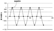
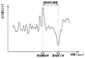
例えば、第2加速度センサ11bの検出信号が、第2加速度センサ11bに対して加速度がタイヤ3の径方向外向きに働いているときを正、径方向内向きに働いている場合を負として表されるとする。この場合において、第2加速度センサ11bの検出信号から直流成分となる遠心加速度を取り除いた波形を生成すると、図4に示す振動波形となる。すなわち、タイヤマウントセンサ1がタイヤ3の中心、つまり車軸と同じ高さに位置しているときには重力加速度が0Gとなる。また、タイヤマウントセンサ1がタイヤ3の上方に位置しているときには重力加速度が−1Gとなり、タイヤ3の下方に位置しているときには重力加速度が1Gとなる。
For example, the detection signal of the
このため、第2加速度センサ11bの検出信号から重力加速度成分を抽出することで、タイヤマウントセンサ1がタイヤ3のどの角度に位置している状態であるかを検出できる。そして、接地角度はタイヤマウントセンサ1がタイヤ3の下方に位置していて接地区間中となっているときであることから、第2加速度センサ11bの検出信号が示す重力加速度成分が1Gの近傍のときに接地角度になる。したがって、角度検出部13aは、第2加速度センサ11bの検出信号の重力加速度成分を抽出し、重力加速度が所定の閾値、例えば図4中に示したように0.8G以上であれば、接地角度になり得る期間中である判定している。そして、角度検出部13aは、接地角度になり得る期間中であると判定すると、測定期間中であるとして区間抽出部13bに伝えている。
For this reason, it is possible to detect at which angle of the
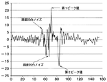
区間抽出部13bは、角度検出部13aから伝えられた測定期間中に、第1加速度センサ11aの出力電圧で表される検出信号のピーク値を検出することで接地区間を抽出する。タイヤ回転時における第1加速度センサ11aの出力電圧波形は例えば図5に示す波形となる。この図に示されるように、タイヤ3の回転に伴ってトレッド31のうち第1加速度センサ11aの配置箇所と対応する部分が接地し始めた接地開始時に、第1加速度センサ11aの出力電圧が極大値をとる。区間抽出部13bでは、この第1加速度センサ11aの出力電圧が極大値をとる接地開始時を第1ピーク値のタイミングとして検出している。さらに、図4に示されるように、タイヤ3の回転に伴ってトレッド31のうち第1加速度センサ11aの配置箇所と対応する部分が接地していた状態から接地しなくなる接地終了時に、第1加速度センサ11aの出力電圧が極小値をとる。区間抽出部13bでは、この第1加速度センサ11aの出力電圧が極小値をとる接地終了時を第2ピーク値のタイミングとして検出している。
The
第1加速度センサ11aの出力電圧が上記のようなタイミングでピーク値をとるのは、以下の理由による。すなわち、タイヤ3の回転に伴ってトレッド31のうち第1加速度センサ11aの配置箇所と対応する部分が接地する際、第1加速度センサ11aの近傍においてタイヤ3のうちそれまで略円筒面であった部分が押圧されて平面状に変形する。このときの衝撃を受けることで、第1加速度センサ11aの出力電圧が第1ピーク値をとる。また、タイヤ3の回転に伴ってトレッド31のうち第1加速度センサ11aの配置箇所と対応する部分が接地面から離れる際には、第1加速度センサ11aの近傍においてタイヤ3は押圧が解放されて平面状から略円筒状に戻る。このタイヤ3の形状が元に戻るときの衝撃を受けることで、第1加速度センサ11aの出力電圧が第2ピーク値をとる。このようにして、第1加速度センサ11aの出力電圧が接地開始時と接地終了時でそれぞれ第1、第2ピーク値をとるのである。また、タイヤ3が押圧される際の衝撃の方向と、押圧から開放される際の衝撃の方向は逆方向であるため、出力電圧の符号も逆方向となる。
The reason why the output voltage of the first acceleration sensor 11a takes the peak value at the above timing is as follows. That is, when the portion of the
そして、区間抽出部13bは、第1、第2ピーク値のタイミングを含めた検出信号のデータを抽出することで第1加速度センサ11aの接地区間を抽出し、接地区間中であることをレベル算出部13cに伝える。
Then, the
このように、角度検出部13aによって、接地角度になり得る期間中であることを判定し、この期間を測定期間として区間抽出部13bによる接地区間の抽出を行うようにしている。このため、第1加速度センサ11aの検出信号に路面の凹凸に基づく振動のノイズが重畳されていても、接地区間を誤判定してしまうことを抑制できる。すなわち、図6に示すように、凹凸が大きい路面を走行する場合には、図5に示す路面が小さなアスファルト路などを走行する場合と比較して、路面の凹凸に基づく振動のノイズが大きくなる。このため、大きなノイズが第1ピーク値や第2ピーク値として誤って検出され得る。しかしながら、本実施形態のように、角度検出部13aによって測定期間を限定することで、路面の凹凸に基づく振動のノイズを誤って第1ピーク値や第2ピーク値として検出しまわないようにできる。よって、凹凸の大きな走行路面であっても接地区間を誤判定することを抑制することが可能となる。
In this way, the
また、第1加速度センサ11aの出力電圧が第2ピーク値をとるタイミングが第1加速度センサ11aの接地終了時となるため、区間抽出部13bは、このタイミングでRF回路14に送信トリガを送っている。これにより、RF回路14より、後述するようにデータ生成部13dで作成されるμデータなどの路面データを送信させている。このように、RF回路14によるデータ送信を常に行うのではなく、第1加速度センサ11aの接地終了時に限定して行うようにしているため、消費電力を低減することが可能となる。
Also, since the timing at which the output voltage of the first acceleration sensor 11a takes the second peak value is when the grounding of the first acceleration sensor 11a ends, the
レベル算出部13cは、区間抽出部13bから接地区間中であることが伝えられると、その期間中に第1加速度センサ11aの出力電圧に含まれるタイヤ3の振動に起因する高周波成分のレベルを算出する。そして、レベル算出部13cは、その算出結果をμデータなどの路面データとしてデータ生成部13dに伝える。ここで、路面μなどの路面状態を表わす指標として高周波成分のレベルを算出するようにしているが、その理由について図7A、図7Bおよび図8を参照して説明する。
The
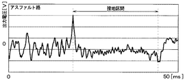
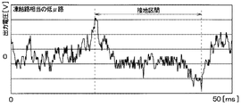
図7Aは、アスファルト路のように路面μが比較的大きな高μ路面を走行している場合における第1加速度センサ11aの出力電圧の変化を示している。また、図7Bは、凍結路の相当する程度に路面μが比較的小さな低μ路面を走行している場合における第1加速度センサ11aの出力電圧の変化を示している。 FIG. 7A shows a change in the output voltage of the first acceleration sensor 11a when traveling on a high μ road surface having a relatively large road surface μ such as an asphalt road. FIG. 7B shows a change in the output voltage of the first acceleration sensor 11a when traveling on a low μ road surface where the road surface μ is relatively small to the extent corresponding to the frozen road.
これらの図から分かるように、路面μにかかわらず、接地区間の最初と最後、つまり第1加速度センサ11aの接地開始時と接地終了時において第1、第2ピーク値が現れる。しかしながら、路面μの影響で、第1加速度センサ11aの出力電圧が変化する。例えば、低μ路面の走行時のように路面μが低いときには、タイヤ3のスリップによる細かな高周波振動が出力電圧に重畳される。このようなタイヤ3のスリップによる細かな高周波信号は、高μ路面の走行時のように路面μが高い場合にはあまり重畳されない。
As can be seen from these figures, regardless of the road surface μ, the first and second peak values appear at the beginning and end of the contact section, that is, at the start and end of contact of the first acceleration sensor 11a. However, the output voltage of the first acceleration sensor 11a changes due to the influence of the road surface μ. For example, when the road surface μ is low, such as when traveling on a low μ road surface, fine high-frequency vibration due to slip of the
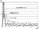
このため、路面μが高い場合と低い場合それぞれについて、接地区間中における出力電圧の周波数解析を行うと、図8に示す結果となる。すなわち、低周波域では路面μが高い場合と低い場合のいずれを走行する場合にも高いレベルになるが、1kHz以上の高周波域では路面μが低い場合の方が高い場合よりも高いレベルになる。このため、第1加速度センサ11aの出力電圧の高周波成分のレベルが路面状態を表す指標となる。 For this reason, when the frequency analysis of the output voltage in the ground section is performed for each of the cases where the road surface μ is high and low, the result shown in FIG. 8 is obtained. In other words, in the low frequency range, the level is high when the road surface μ is high or low, but in the high frequency range of 1 kHz or higher, the level is higher when the road surface μ is low than when it is high. . For this reason, the level of the high frequency component of the output voltage of the first acceleration sensor 11a is an index representing the road surface state.
したがって、レベル算出部13cによって接地区間中における第1加速度センサ11aの出力電圧の高周波成分のレベルを算出することで、これをμデータとすることが可能となる。また、μデータから、例えば路面μが低い場合に凍結路と判定するなど、路面μと対応する路面の種類を路面状態として検出することもできる。
Therefore, by calculating the level of the high frequency component of the output voltage of the first acceleration sensor 11a during the grounding section by the
例えば、高周波成分のレベルは、第1加速度センサ11aの出力電圧から高周波成分を抽出し、接地区間中に抽出した高周波成分を積分することで算出することができる。具体的には、路面状態や路面μに応じて変化すると想定される周波数帯域fa〜fbの高周波成分をフィルタリングなどによって抽出し、周波数解析によって取り出した周波数帯域fa〜fbの高周波数成分の電圧を積分する。例えば、図示しないコンデンサにチャージさせる。このようにすれば、高μ路面を走行している場合のように路面μが高い場合の方が低μ路面を走行している場合のように路面μが低い場合よりもチャージ量が多くなる。このチャージ量をμデータとして用いて、μデータが示すチャージ量が多いほど路面μが低いというように路面μを推定できる。 For example, the level of the high frequency component can be calculated by extracting the high frequency component from the output voltage of the first acceleration sensor 11a and integrating the high frequency component extracted during the grounding section. Specifically, the high frequency components of the frequency bands fa to fb that are assumed to change according to the road surface condition and the road surface μ are extracted by filtering or the like, and the voltages of the high frequency components of the frequency bands fa to fb extracted by the frequency analysis are obtained. Integrate. For example, a capacitor (not shown) is charged. In this way, the amount of charge increases when the road surface μ is high, such as when traveling on a high μ road surface, compared to when the road surface μ is low, such as when traveling on a low μ road surface. . Using this charge amount as the μ data, it is possible to estimate the road surface μ such that the larger the charge amount indicated by the μ data, the lower the road surface μ.
データ生成部13dは、基本的には、レベル算出部13cでの算出結果に基づいて路面データを生成している。例えば、データ生成部13dは、μデータをそのまま路面データとして採用したり、μデータから凍結路やアスファルト路のような路面状態を求めて、それを示すデータを路面データとして生成している。
The
また、上記したように、本実施形態の場合は、温度センサ12によって走行路面の温度を測定している。これに基づき、データ生成部13dは、温度センサ12の検出信号を入力することで路面温度を取得し、取得した路面温度から路面の種類を検出したり、μデータの補正もしくはμデータから得た路面の種類の補正を行っている。
As described above, in the present embodiment, the temperature of the traveling road surface is measured by the
例えば、温度センサ12で検出された路面温度が0℃よりも低いマイナスであった場合には、データ生成部13dは、路面の種類として路面が凍結状態であることを検出している。さらに、データ生成部13dは、第1加速度センサ11aの検出信号の高周波成分から求めたμデータもしくはμデータが示す路面の種類が温度センサ12で検出された路面温度と合致しない場合には、それを補正したり、路面状態の検出結果として採用しないようにする。例えば、第1加速度センサ11aの検出信号の高周波成分から求めた路面の種類が凍結状態であった場合において、温度センサ12で検出された路面温度が40℃であったときには、凍結状態という路面の種類の検出結果に誤りがあると考えられる。この場合には、データ生成部13dは、レベル算出部13cから伝えられる結果を路面の種類の検出結果としては採用しないようにする。同様に、μデータが示す路面μが路面温度から得た路面の種類と合致しない場合、例えば路面温度から凍結状態と検出されているのにμデータが示す路面μが高い場合には、μデータが示す路面μを補正して補正前よりも低い値にしたりする。
For example, when the road surface temperature detected by the
RF回路14は、データ生成部13dから伝えられたμデータなどの路面データを受信機21に対して送信する送信部を構成するものである。RF回路14と受信機21との間の通信は、例えば、Bluetooth(登録商標)などの公知の近距離無線通信技術によって実施可能である。路面データを送信するタイミングについては任意であるが、上記したように、本実施形態では、第1加速度センサ11aの接地終了時に区間抽出部13bから送信トリガが送られることでRF回路14から路面データが送られるようになっている。このように、RF回路14によるデータ送信を常に行うのではなく、第1加速度センサ11aの接地終了時に限定して行うようにしているため、消費電力を低減することが可能となる。
The
また、路面データについては、車両に備えられたタイヤ3毎に予め備えられている車輪の固有識別情報(以下、ID情報という)と共に送られる。各車輪の位置については、車輪が車両のどの位置に取り付けられているかを検出する周知の車輪位置検出装置によって特定できることから、受信機21にID情報と共に路面データを伝えることで、どの車輪のデータであるかが判別可能になる。
Further, the road surface data is sent together with the unique identification information (hereinafter referred to as ID information) of the wheels provided in advance for each
電源15は、例えば電池などによって構成され、タイヤマウントセンサ1の各部を駆動するための電源供給を行っている。
The
一方、受信機21は、タイヤマウントセンサ1より送信された路面データを受信し、これに基づいて路面状態を推定すると共に推定した路面状態を報知装置22に伝え、必要に応じて報知装置22より路面状態をドライバに伝える。これにより、ドライバは路面状態に対応した運転を心掛けるようになり、車両の危険性を回避することが可能となる。例えば、報知装置22を通じて推定された路面状態を常に表示するようにしても良いし、推定された路面状態がウェット路や凍結路や低μ路等のように運転をより慎重に行う必要があるときにのみ路面状態を表示してドライバに警告するようにしても良い。また、受信機21からブレーキ制御用の電子制御装置(以下、ECUという)などの車両運動制御を実行するためのECUに対して路面状態を伝えれば、伝えられた路面状態に基づいて車両運動制御が実行されるようにすることもできる。
On the other hand, the
報知装置22は、例えばメータ表示器などで構成され、ドライバに対して路面状態を報知する際に用いられる。報知装置22をメータ表示器で構成する場合、ドライバが車両の運転中に視認可能な場所に配置され、例えば車両におけるインストルメントパネル内に設置される。メータ表示器は、受信機21から路面状態が伝えられると、その路面状態が把握できる態様で表示を行うことで、視覚的にドライバに対して路面状態を報知することができる。
The notification device 22 is composed of, for example, a meter display and is used when notifying the driver of the road surface state. When the notification device 22 is configured by a meter display, the notification device 22 is disposed at a place where the driver can visually recognize the vehicle while driving, for example, in an instrument panel of the vehicle. When the road surface state is transmitted from the
なお、報知装置22をブザーや音声案内装置などで構成することもできる。その場合、報知装置22は、ブザー音や音声案内によって、聴覚的にドライバに対して路面状態を報知することができる。また、視覚的な報知を行う報知装置22としてメータ表示器を例に挙げたが、ヘッドアップディスプレイなどの情報表示を行う表示器によって報知装置22を構成しても良い。 Note that the notification device 22 may be constituted by a buzzer, a voice guidance device, or the like. In that case, the notification device 22 can audibly notify the driver of the road surface state by a buzzer sound or voice guidance. In addition, although the meter display device has been exemplified as the notification device 22 that performs visual notification, the notification device 22 may be configured by a display device that displays information such as a head-up display.
以上のようにして、本実施形態にかかる路面状態推定装置100が構成されている。なお、車体側システム2を構成する各部が例えばCAN(Controller Area Networkの略)通信などによる車内LAN(Local Area Networkの略)を通じて接続されている。このため、車内LANを通じて各部が互いに情報伝達できるようになっている。
As described above, the road surface
続いて、本実施形態にかかる路面状態推定装置100におけるタイヤマウントセンサ1の作動について、図9を参照して説明する。図9は、タイヤマウントセンサ1でシステム的に行われる処理をフローチャートとして示したものである。
Next, the operation of the
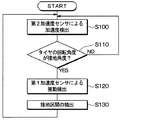
各車輪のタイヤマウントセンサ1では、ステップS100に示されるように、第2加速度センサ11bが電源15からの電力供給に基づいてタイヤ3の遠心方向の加速度検出を行っている。そして、ステップS110に示されるように、角度検出部13aによって第2加速度センサ11bの検出信号に基づいてタイヤ3の回転角度が接地角度になる角度であるか否かを判定する。具体的には、第2加速度センサ11bの検出信号の重力加速度成分を抽出し、重力加速度が所定の閾値、例えば0.8G以上であれば、タイヤ3の回転角度が接地角度になる角度であると判定する。ここで肯定判定されるとステップS120に進み、否定判定されるとステップS100の処理の戻る。
In the
ステップS120では、制御部13において、第1加速度センサ11aの検出信号に基づく振動検出をスタートする。そして、ステップS130において、第1加速度センサ11aの検出信号から第1ピーク値および第2ピーク値を検出することで接地区間を抽出する。
In step S120, the
このような動作が繰り返されることで、第1加速度センサ11aの検出信号の中から接地区間中の振動のみを的確に取得することが可能となる。そして、この後の処理については図示していないが、接地区間中の振動が得られると、それに基づいて路面状態が検出され路面データが生成されて、路面データがRF回路14を通じて受信機21側に送信される。これが受信機21に受信され、路面データに基づく路面状態の推定が行われ、推定された路面状態を報知装置22に伝えるなどの処理が行われる。また、タイヤ3の回転角度が接地角度でなくなると、再び接地角度になるまでの間、第1加速度センサ11aによる振動検出が行われなくなる。
By repeating such an operation, it is possible to accurately acquire only the vibration during the ground contact section from the detection signal of the first acceleration sensor 11a. Although the subsequent processing is not shown, when vibration during the ground contact section is obtained, the road surface state is detected and road surface data is generated, and the road surface data is transmitted to the
以上説明したように、本実施形態にかかる路面状態推定装置100では、タイヤ3の回転角度に基づいて接地角度になる期間にのみ第1加速度センサ11aの検出信号に基づく接地区間の抽出を行うようにしている。このため、第1加速度センサ11aの検出信号に路面の凹凸に基づく振動のノイズが重畳されていても、接地区間を誤判定してしまうことを抑制できる。よって、凹凸の大きな走行路面であっても接地区間を誤判定することを抑制することが可能となる。
As described above, in the road surface
(第2実施形態)
第2実施形態について説明する。本実施形態は、第1実施形態に対して角度検出部13aの構成を変更したものであり、その他については第1実施形態と同様であるため、第1実施形態と異なる部分についてのみ説明する。
(Second Embodiment)
A second embodiment will be described. In the present embodiment, the configuration of the
上記第1実施形態では、角度検出部13aにて、第2加速度センサ11bの検出信号が示す加速度が所定の閾値以上になったときを接地角度になる回転角度として検出している。これに対して、本実施形態では、角度検出部13aにて、第2加速度センサ11bの検出信号が示す加速度と車輪速度とから接地角度になる回転角度を検出する。
In the first embodiment, the
図4に示したように、第2加速度センサ11bの検出信号から直流成分となる遠心加速度を取り除くと、タイヤ3の回転に伴って振幅する振動波形となる。この振動波形の周期は、タイヤ3の速度に応じた振幅となることから、タイヤ3の速度が判れば、次に接地角度になるまでの時間が判る。このため、本実施形態では、所定の回転角度となる加速度として、加速度が所定値、例えば0Gとなるタイミングとタイヤ3の速度とから、次に接地角度になると想定される期間を演算する。そして、その期間を含むように測定期間を設定し、測定期間中であることを区間抽出部13bに伝えるようにする。
As shown in FIG. 4, when centrifugal acceleration, which is a direct current component, is removed from the detection signal of the
例えば、加速度が0Gとなってから加速度が増加する場合、次に加速度が0Gになるまでの間に接地角度になる。この場合、加速度がマイナス値から0Gになったときに、タイヤ3の速度から次に接地角度になると想定される期間を演算する。タイヤ3の速度については、例えば前回加速度が0Gになってから今回加速度が0Gになるまでの期間や、加速度の振幅の最大値同士の時間間隔のように加速度の振幅の1周期の時間などに基づいて算出できる。このときに算出されたタイヤ3の速度が例えば100km/hであれば、25ms後が次に接地角度になる時間と想定される。このため、接地角度になる時間を含む期間、例えば20〜30msを測定期間として設定する。
For example, when the acceleration increases after the acceleration becomes 0G, the contact angle is reached until the acceleration becomes 0G next time. In this case, when the acceleration is changed from a negative value to 0 G, a period that is assumed to be the next contact angle is calculated from the speed of the
このように、角度検出部13aにて、第2加速度センサ11bの検出信号が示す加速度とタイヤ3の速度とから接地角度になる回転角度を検出することもできる。このようにしても、第1実施形態と同様の効果を得ることができる。
As described above, the
(他の実施形態)
本発明は上記した実施形態に限定されるものではなく、特許請求の範囲に記載した範囲内において適宜変更が可能である。
(Other embodiments)
The present invention is not limited to the embodiment described above, and can be appropriately changed within the scope described in the claims.
例えば、上記実施形態においては、振動検出部を構成する第1加速度センサ11aの検出信号から接地区間を特定し、接地区間中の検出信号における高周波成分のレベルの算出結果を路面状態が示された路面データとして用いている。しかしながら、これは振動検出部での検出信号を用いて路面状態を検出する手法の一例を示したに過ぎず、振動検出部での検出信号を用いた他の手法によって路面状態を検出しても良い。また、振動検出部を第1加速度センサ11aによって構成する場合を例示したが、他の振動検出を行うことができる素子、例えば圧電素子などによって振動検出部を構成することもできる。また、電源15についても、電池に限らず、発電素子などによって構成することもできる。例えば、振動検出素子を用いれば、振動検出素子によって振動検出部を構成しつつ電源15を構成することもできる。
For example, in the above-described embodiment, the ground section is specified from the detection signal of the first acceleration sensor 11a constituting the vibration detection unit, and the road surface state is obtained by calculating the level of the high frequency component in the detection signal in the ground section. Used as road surface data. However, this is only an example of a method for detecting the road surface state using the detection signal at the vibration detection unit, and even if the road surface state is detected by another method using the detection signal at the vibration detection unit. good. Moreover, although the case where the vibration detection part is comprised by the 1st acceleration sensor 11a was illustrated, the vibration detection part can also be comprised by the element which can perform another vibration detection, for example, a piezoelectric element. Further, the
また、上記実施形態の場合、μデータや路面状態、より詳しくは路面の種類を示した路面データとしているが、路面状態を示すデータであれば良く、振動検出部の出力電圧波形のうちの第1ピーク値から第2ピーク値までのデータをそのまま路面データとしても良い。 In the case of the above embodiment, μ data and road surface state, more specifically, road surface data indicating the type of road surface are used. However, any data indicating the road surface state may be used, and the first of the output voltage waveforms of the vibration detection unit. Data from the first peak value to the second peak value may be directly used as road surface data.
また、上記実施形態の場合、受信機21にて、路面データの受信に加えて報知装置22への路面状態の通知などを行う制御部としての役割を果たしている。しかしながら、これは一例を示したに過ぎず、受信機21とは別に制御部を備えても良いし、ブレーキECUなどの他のECUを制御部として機能させるようにしても良い。
Moreover, in the case of the said embodiment, in addition to reception of road surface data, the
1 タイヤマウントセンサ
2 車体側システム
11a、11b 第1、第2加速度センサ
13 制御部
13a 角度検出部
13b 区間抽出部
13c レベル算出部
13d データ生成部
21 受信機
100 路面状態推定装置
DESCRIPTION OF
Claims (5)
前記タイヤの振動の大きさに応じた検出信号を出力する振動検出部(11a)と、
前記タイヤの径方向の加速度に応じた検出信号を出力する加速度センサ(11b)と、
前記加速度センサの検出信号に基づいて、前記タイヤの回転角度が、該タイヤの1回転中における前記トレッドのうちの前記振動検出部の配置箇所と対応する部分が接地する接地角度になることを検出し、該接地角度となる期間を含む測定期間を設定すると共に、該測定期間中に、前記振動検出部の検出信号から前記配置箇所と対応する部分が接地している接地区間を抽出し、該接地区間中における前記振動検出部の検出信号に基づいて路面状態が表された路面データを生成する信号処理部(13)と、
前記路面データを送信する送信部(14)と、を有しているタイヤマウントセンサ。 A tire mount sensor attached to the back surface of the tread (31) of the tire (3),
A vibration detector (11a) that outputs a detection signal corresponding to the magnitude of vibration of the tire;
An acceleration sensor (11b) that outputs a detection signal corresponding to the radial acceleration of the tire;
Based on the detection signal of the acceleration sensor, the rotation angle of the tire is detected to be a contact angle at which a portion of the tread corresponding to the position where the vibration detection unit is disposed is grounded during one rotation of the tire. And setting a measurement period including a period corresponding to the grounding angle, and extracting a grounding section in which the portion corresponding to the placement location is grounded from the detection signal of the vibration detecting unit during the measurement period, A signal processing unit (13) for generating road surface data representing a road surface state based on a detection signal of the vibration detection unit in the ground contact section;
A tire mount sensor having a transmitter (14) for transmitting the road surface data.
前記信号処理部は、前記加速度センサの検出信号から重力加速度成分を抽出し、重力加速度が所定の閾値以上になると前記配置箇所と対応する部分が接地する接地角度になることを検出し、前記測定時間を設定する請求項1に記載のタイヤマウントセンサ。 The acceleration sensor outputs, as the detection signal, a signal that is positive when the acceleration is working radially outward of the tire, and is negative when the acceleration is working radially inward,
The signal processing unit extracts a gravitational acceleration component from the detection signal of the acceleration sensor, detects that the gravitational acceleration is equal to or greater than a predetermined threshold, detects that the portion corresponding to the arrangement location is a grounding angle at which the grounding is performed, and the measurement The tire mount sensor according to claim 1 which sets time.
前記信号処理部は、前記加速度センサの検出信号から重力加速度成分を抽出し、前記重力加速度が所定値になってから所定時間後に前記配置箇所と対応する部分が接地する接地角度になることを検出し、前記測定時間を設定する請求項1に記載のタイヤマウントセンサ。 The acceleration sensor outputs, as the detection signal, a signal that is positive when the acceleration is working radially outward of the tire, and is negative when the acceleration is working radially inward,
The signal processing unit extracts a gravitational acceleration component from the detection signal of the acceleration sensor, and detects that a portion corresponding to the arrangement location is grounded after a predetermined time after the gravitational acceleration reaches a predetermined value. The tire mount sensor according to claim 1, wherein the measurement time is set.
車体側に備えられ、前記送信部から送信された前記路面データを受信すると共に、前記路面データに基づいて路面状態を推定する制御部(21)を有する車体側システム(2)と、を備えた路面状態推定装置。 The tire mount sensor according to any one of claims 1 to 4,
A vehicle body side system (2) provided on the vehicle body side, having the control unit (21) for receiving the road surface data transmitted from the transmission unit and estimating a road surface state based on the road surface data. Road surface state estimation device.
Priority Applications (3)
| Application Number | Priority Date | Filing Date | Title |
|---|---|---|---|
| JP2016138653A JP6627670B2 (en) | 2016-07-13 | 2016-07-13 | Tire mount sensor and road surface condition estimation device including the same |
| PCT/JP2017/023192 WO2018012249A1 (en) | 2016-07-13 | 2017-06-23 | Tire-mounted sensor and road surface condition estimating device including same |
| US16/243,113 US11034356B2 (en) | 2016-07-13 | 2019-01-09 | Tire-mounted sensor and road surface condition estimation apparatus including the same |
Applications Claiming Priority (1)
| Application Number | Priority Date | Filing Date | Title |
|---|---|---|---|
| JP2016138653A JP6627670B2 (en) | 2016-07-13 | 2016-07-13 | Tire mount sensor and road surface condition estimation device including the same |
Publications (2)
| Publication Number | Publication Date |
|---|---|
| JP2018009869A true JP2018009869A (en) | 2018-01-18 |
| JP6627670B2 JP6627670B2 (en) | 2020-01-08 |
Family
ID=60951807
Family Applications (1)
| Application Number | Title | Priority Date | Filing Date |
|---|---|---|---|
| JP2016138653A Expired - Fee Related JP6627670B2 (en) | 2016-07-13 | 2016-07-13 | Tire mount sensor and road surface condition estimation device including the same |
Country Status (3)
| Country | Link |
|---|---|
| US (1) | US11034356B2 (en) |
| JP (1) | JP6627670B2 (en) |
| WO (1) | WO2018012249A1 (en) |
Families Citing this family (12)
| Publication number | Priority date | Publication date | Assignee | Title |
|---|---|---|---|---|
| JP6528676B2 (en) * | 2015-12-25 | 2019-06-12 | 株式会社デンソー | Tire mount sensor |
| JP6551463B2 (en) * | 2016-07-13 | 2019-07-31 | 株式会社デンソー | Tire mount sensor and road surface condition estimation apparatus including the same |
| JP2018026111A (en) * | 2016-08-05 | 2018-02-15 | 株式会社デンソー | Tire-mounted sensor and chain regulation management system |
| JP7009098B2 (en) * | 2017-07-19 | 2022-01-25 | 株式会社ブリヂストン | Road surface condition estimation method |
| JP6907965B2 (en) * | 2018-02-01 | 2021-07-21 | 株式会社Soken | Road surface condition determination device |
| US11472235B2 (en) * | 2019-01-22 | 2022-10-18 | American Tire Distributors, Inc. | Tire health monitoring systems and methods thereto |
| EP4267413B1 (en) * | 2020-12-22 | 2025-02-05 | Compagnie Generale Des Etablissements Michelin | Electronic member transmitting an item of identification information during a state change |
| CN114851784B (en) | 2021-02-04 | 2023-12-01 | 武汉杰开科技有限公司 | Vehicle motion state monitoring method, and related chip, device and system |
| US20240190366A1 (en) * | 2022-12-08 | 2024-06-13 | The Goodyear Tire & Rubber Company | Hydroplaning detection method and system |
| EP4610120A1 (en) * | 2024-03-01 | 2025-09-03 | Volvo Truck Corporation | Estimating status of a wheel based on acceleration data |
| US20250297923A1 (en) * | 2024-03-22 | 2025-09-25 | Robert Bosch Gmbh | Prediction and identification of potential semi-trailer truck system anomalies |
| CN121448402A (en) * | 2024-07-31 | 2026-02-03 | 比亚迪股份有限公司 | Road surface type identification method, system, electronic device and vehicle |
Citations (7)
| Publication number | Priority date | Publication date | Assignee | Title |
|---|---|---|---|---|
| JP2005059800A (en) * | 2003-08-19 | 2005-03-10 | Bridgestone Corp | Method and device for estimating road surface condition |
| JP2011203017A (en) * | 2010-03-24 | 2011-10-13 | Bridgestone Corp | Method of estimating road surface condition |
| US20140007683A1 (en) * | 2012-07-06 | 2014-01-09 | CONTINENT AUTOMOTIVE GmbH | Method for determining the angular position of an electronic module fixed to the inner face of the tread of a tire |
| JP2016022761A (en) * | 2014-07-16 | 2016-02-08 | 株式会社日本自動車部品総合研究所 | Tire condition detection device |
| JP2016112967A (en) * | 2014-12-12 | 2016-06-23 | 株式会社日本自動車部品総合研究所 | Vehicle control system |
| JP2017081380A (en) * | 2015-10-27 | 2017-05-18 | 株式会社日本自動車部品総合研究所 | Road surface condition estimation device |
| JP2017083264A (en) * | 2015-10-27 | 2017-05-18 | 株式会社日本自動車部品総合研究所 | Road surface condition estimation device |
Family Cites Families (7)
| Publication number | Priority date | Publication date | Assignee | Title |
|---|---|---|---|---|
| EP1219515B1 (en) * | 2000-06-23 | 2011-01-19 | Kabushiki Kaisha Bridgestone | Method for estimating vehicular running state, vehicular running state estimating device, vehicle control device, and tire wheel |
| CN1321838C (en) * | 2001-12-21 | 2007-06-20 | 株式会社普利司通 | Method and apparatus for estimating road surface state and tire running state, abs and vehicle control using the same |
| JP4517610B2 (en) * | 2003-09-16 | 2010-08-04 | トヨタ自動車株式会社 | Tire state quantity detection device |
| EP1897706B1 (en) * | 2005-06-17 | 2014-12-24 | Kabushiki Kaisha Bridgestone | Road surface state estimating method, road surface state estimating tire, road surface state estimating device, and vehicle control device |
| DE102012204141A1 (en) * | 2012-03-16 | 2013-09-19 | Continental Automotive Gmbh | Device and method for determining an absolute angular position of a wheel of a vehicle |
| FR3014366B1 (en) * | 2013-12-05 | 2016-01-08 | Continental Automotive France | METHOD FOR DETERMINING THE IMPRESSION OF A WHEEL TIRE ON THE GROUND |
| JP6318743B2 (en) | 2014-03-18 | 2018-05-09 | 株式会社Soken | Tire condition detection device |
-
2016
- 2016-07-13 JP JP2016138653A patent/JP6627670B2/en not_active Expired - Fee Related
-
2017
- 2017-06-23 WO PCT/JP2017/023192 patent/WO2018012249A1/en not_active Ceased
-
2019
- 2019-01-09 US US16/243,113 patent/US11034356B2/en not_active Expired - Fee Related
Patent Citations (7)
| Publication number | Priority date | Publication date | Assignee | Title |
|---|---|---|---|---|
| JP2005059800A (en) * | 2003-08-19 | 2005-03-10 | Bridgestone Corp | Method and device for estimating road surface condition |
| JP2011203017A (en) * | 2010-03-24 | 2011-10-13 | Bridgestone Corp | Method of estimating road surface condition |
| US20140007683A1 (en) * | 2012-07-06 | 2014-01-09 | CONTINENT AUTOMOTIVE GmbH | Method for determining the angular position of an electronic module fixed to the inner face of the tread of a tire |
| JP2016022761A (en) * | 2014-07-16 | 2016-02-08 | 株式会社日本自動車部品総合研究所 | Tire condition detection device |
| JP2016112967A (en) * | 2014-12-12 | 2016-06-23 | 株式会社日本自動車部品総合研究所 | Vehicle control system |
| JP2017081380A (en) * | 2015-10-27 | 2017-05-18 | 株式会社日本自動車部品総合研究所 | Road surface condition estimation device |
| JP2017083264A (en) * | 2015-10-27 | 2017-05-18 | 株式会社日本自動車部品総合研究所 | Road surface condition estimation device |
Also Published As
| Publication number | Publication date |
|---|---|
| JP6627670B2 (en) | 2020-01-08 |
| WO2018012249A1 (en) | 2018-01-18 |
| US11034356B2 (en) | 2021-06-15 |
| US20190143987A1 (en) | 2019-05-16 |
Similar Documents
| Publication | Publication Date | Title |
|---|---|---|
| JP6627670B2 (en) | Tire mount sensor and road surface condition estimation device including the same | |
| JP6614073B2 (en) | Road surface condition estimation device | |
| JP6620787B2 (en) | Road surface condition estimation device | |
| JP6558266B2 (en) | Danger avoidance device for vehicles | |
| JP2018016300A (en) | Wheel position detection device | |
| JP2018009974A (en) | Tire-mounted sensor and road surface state estimation device including the same | |
| JP6547793B2 (en) | Tire mount sensor, diagnosis history storage device and diagnosis notification device | |
| JP6551274B2 (en) | Hydroplaning judgment device | |
| JP6318743B2 (en) | Tire condition detection device | |
| JP6365503B2 (en) | Road surface condition estimation device | |
| JP6551463B2 (en) | Tire mount sensor and road surface condition estimation apparatus including the same | |
| JP2016112967A (en) | Vehicle control system | |
| WO2017221578A1 (en) | Road surface condition estimation device | |
| WO2017187927A1 (en) | Road surface condition detecting device | |
| WO2018003693A1 (en) | Tire mounted sensor and road surface condition estimating device including same | |
| WO2018030001A1 (en) | Road surface state assessment apparatus | |
| JP6601261B2 (en) | Road surface condition estimation device | |
| WO2018012251A1 (en) | Wheel position detecting device | |
| WO2018012250A1 (en) | Tire-mounted sensor and road surface condition estimating device including same | |
| WO2018030000A1 (en) | Tire mounted sensor, diagnosis history storage device, and diagnosis notification device | |
| JP2006168568A (en) | Road surface roughness detector |
Legal Events
| Date | Code | Title | Description |
|---|---|---|---|
| A621 | Written request for application examination |
Free format text: JAPANESE INTERMEDIATE CODE: A621 Effective date: 20180606 |
|
| A131 | Notification of reasons for refusal |
Free format text: JAPANESE INTERMEDIATE CODE: A131 Effective date: 20190604 |
|
| A521 | Request for written amendment filed |
Free format text: JAPANESE INTERMEDIATE CODE: A523 Effective date: 20190726 |
|
| TRDD | Decision of grant or rejection written | ||
| A01 | Written decision to grant a patent or to grant a registration (utility model) |
Free format text: JAPANESE INTERMEDIATE CODE: A01 Effective date: 20191105 |
|
| A61 | First payment of annual fees (during grant procedure) |
Free format text: JAPANESE INTERMEDIATE CODE: A61 Effective date: 20191118 |
|
| R151 | Written notification of patent or utility model registration |
Ref document number: 6627670 Country of ref document: JP Free format text: JAPANESE INTERMEDIATE CODE: R151 |
|
| R250 | Receipt of annual fees |
Free format text: JAPANESE INTERMEDIATE CODE: R250 |
|
| R250 | Receipt of annual fees |
Free format text: JAPANESE INTERMEDIATE CODE: R250 |
|
| LAPS | Cancellation because of no payment of annual fees |