JP2018009847A - Extraction method of liquid level shape, device and program - Google Patents
Extraction method of liquid level shape, device and program Download PDFInfo
- Publication number
- JP2018009847A JP2018009847A JP2016137867A JP2016137867A JP2018009847A JP 2018009847 A JP2018009847 A JP 2018009847A JP 2016137867 A JP2016137867 A JP 2016137867A JP 2016137867 A JP2016137867 A JP 2016137867A JP 2018009847 A JP2018009847 A JP 2018009847A
- Authority
- JP
- Japan
- Prior art keywords
- liquid level
- level height
- difference
- original data
- time
- Prior art date
- Legal status (The legal status is an assumption and is not a legal conclusion. Google has not performed a legal analysis and makes no representation as to the accuracy of the status listed.)
- Granted
Links
Images


Landscapes
- Measurement Of Levels Of Liquids Or Fluent Solid Materials (AREA)
- Continuous Casting (AREA)
- Image Analysis (AREA)
Abstract
【課題】容器内の自由液面を撮影した、時間的に連続する画像に基づいて、正確な液体の流動状況、液面挙動を把握できるようにする。【解決手段】液面形状の抽出装置100において、入力部101は、カメラ300で撮影した容器内の自由液面の動画像データを入力する。原データ作成部102は、入力部101で入力する動画像データを用いて、各時間において一水平方向の各位置で液面高さが単一に定まる原データを作成する。原データは、各時刻での画像について、例えば動的計画法により曲線を抽出する手法で作成される。液面高さ推定部103は、原データ作成部102で作成した原データを対象として、原データと液面高さの計算値との差分に関する項と、液面高さの計算値の時間差分に関する項と、液面高さの計算値の空間差分に関する項とを含む評価関数を構築し、この評価関数を最小にする幅方向の各位置、各時刻の液面高さを推定する。【選択図】図1PROBLEM TO BE SOLVED: To accurately grasp the flow state and liquid level behavior of a liquid on the basis of temporally continuous images obtained by photographing a free liquid level in a container. In a liquid surface shape extracting device 100, an input unit 101 inputs moving image data of a free liquid surface in a container captured by a camera 300. The original data creation unit 102 uses the moving image data input by the input unit 101 to create the original data in which the liquid level height is uniquely determined at each position in one horizontal direction at each time. The original data is created, for example, by a method of extracting a curve by the dynamic programming method for the image at each time. The liquid level height estimating unit 103 targets the original data created by the original data creating unit 102, and a time difference between the term regarding the difference between the original data and the calculated value of the liquid level and the time difference between the calculated values of the liquid level. And the spatial difference of the calculated value of the liquid level are constructed, and the liquid level height at each position and time in the width direction that minimizes this evaluation function is estimated. [Selection diagram] Figure 1
Description
本発明は、容器内の自由液面を撮影した、時間的に連続する画像に基づいて液面形状を抽出する液面形状の抽出方法、装置及びプログラムに関する。 The present invention relates to a liquid surface shape extraction method, apparatus, and program for extracting a liquid surface shape based on temporally continuous images obtained by photographing a free liquid surface in a container.
鉄鋼製造プロセスにおける鋼の連続鋳造工程においては、鋳型内の湯面挙動が鋳片欠陥に影響することが知られている。
従来から、鋳型内の溶鋼の流動状況、湯面挙動を適正化するのに必要な操業因子を明らかにするために、水モデル実験が用いられている(非特許文献1を参照)。水モデル実験とは、透明なアクリル樹脂板等を用いて鋳型を模した容器を作成し、溶鋼の代わりに水を満たすことで、溶鋼の流動状況、湯面挙動を模擬する実験である。このような水モデル実験において水面高さを定量測定する必要がある場合には、非特許文献1で示されるように、通常、フロートとレーザー変位計を利用し、レーザー変位計の設置位置での水面高さを測定することが行われるが、この場合、レーザー変位計で測定していない位置での水面高さを知ることはできなかった。
In the continuous casting process of steel in the steel manufacturing process, it is known that the molten metal surface behavior in the mold affects the slab defects.
Conventionally, a water model experiment has been used in order to clarify operational factors necessary for optimizing the flow of molten steel in a mold and the behavior of the molten metal surface (see Non-Patent Document 1). The water model experiment is an experiment that simulates the flow state of the molten steel and the molten metal surface behavior by creating a container simulating a mold using a transparent acrylic resin plate or the like and filling water instead of the molten steel. When it is necessary to quantitatively measure the water surface height in such a water model experiment, as shown in Non-Patent Document 1, usually, a float and a laser displacement meter are used, and the laser displacement meter is installed at the installation position. Although the water surface height is measured, in this case, the water surface height at a position not measured by the laser displacement meter could not be known.
このような課題に対し、特許文献1では、液体が注水される水槽を挟んで、一方の側に光源を設置し、他方の側に近赤外CCDカメラを設置して、近赤外CCDカメラの撮影画像から輝度比(水槽が空の位置と注水位置との輝度比)を算出し、エッジ処理により液面位置を検出する手法が開示されている。
また、非特許文献2では、ビデオカメラ等の撮影画像から、画像処理技術により曲線を検出する手法が開示されている。非特許文献2では、微分フィルタで山岳の稜線を含むエッジを強調した上で、稜線の連続性を利用し動的計画法により稜線を抽出する手法が提案されている。
In order to solve such a problem, in Patent Document 1, a light source is installed on one side with a water tank into which liquid is poured, and a near-infrared CCD camera is installed on the other side. A method is disclosed in which a luminance ratio (luminance ratio between a position where the water tank is empty and a water injection position) is calculated from the captured image and the liquid level position is detected by edge processing.
Non-Patent Document 2 discloses a method for detecting a curve from a captured image of a video camera or the like by an image processing technique. Non-Patent Document 2 proposes a method for extracting edges by dynamic programming using the continuity of ridge lines after emphasizing edges including mountain ridge lines with a differential filter.
しかしながら、水のような無色透明な液体の気液界面付近は、輝度のコントラストが小さく、特許文献1のような単純なエッジ処理では、画像中のノイズ成分と気液界面を見分けることは困難で、気液界面を見誤ることがある。
また、非特許文献2の手法では、動的計画法による曲線(液面)の抽出の際、画像中のノイズに反応し、液面を誤識別することがある。
このように気液界面を見誤ったり、液面を誤識別したりすると、正確な液体の流動状況、液面挙動を把握できなくなってしまう。
However, in the vicinity of the gas-liquid interface of a colorless and transparent liquid such as water, the brightness contrast is small, and it is difficult to distinguish the noise component and the gas-liquid interface in the image by simple edge processing as in Patent Document 1. The gas-liquid interface may be mistaken.
In the method of Non-Patent Document 2, when extracting a curve (liquid level) by dynamic programming, the liquid level may be erroneously identified in response to noise in the image.
If the gas-liquid interface is mistaken in this way or the liquid level is mistakenly identified, it becomes impossible to grasp the accurate liquid flow state and liquid level behavior.
本発明は上記のような点に鑑みてなされたものであり、容器内の自由液面を撮影した、時間的に連続する画像に基づいて、正確な液体の流動状況、液面挙動を把握できるようにすることを目的とする。 The present invention has been made in view of the above points, and based on temporally continuous images obtained by photographing a free liquid level in a container, it is possible to grasp an accurate liquid flow state and liquid level behavior. The purpose is to do so.
上記の課題を解決するための本発明の要旨は、以下のとおりである。
[1] 容器内の自由液面を撮影した、時間的に連続する複数の画像に基づいて液面形状を抽出する液面形状の抽出方法であって、
前記時間的に連続する画像を用いて作成される、各時間において一水平方向の各位置で液面高さが単一に定まる原データを対象として、
前記原データと液面高さの計算値との差分に関する項と、液面高さの計算値の時間差分に関する項と、液面高さの計算値の空間差分に関する項とを含む評価関数に基づいて、前記一水平方向の各位置、各時刻の液面高さを推定することを特徴とする液面形状の抽出方法。
[2] 前記原データと液面高さの計算値との差分に関する項は、jを前記一水平方向の各位置(j=1、2、・・・、M)、tを各時刻(t=1、2、・・・、T)とし、前記原データにおける液面高さyj(t)と、液面高さの計算値dj(t)との誤差絶対値|yj(t)−dj(t)|の前記一水平方向の各位置、各時刻に関する和で表わされることを特徴とする[1]に記載の液面形状の抽出方法。
[3] スラック変数を用いて前記誤差絶対値を不等式制約に置き換え、前記評価関数を2次計画法により解くことを特徴とする[2]に記載の液面形状の抽出方法。
[4] 前記液面高さの計算値の時間差分に関する項は、時間方向における液面高さの1階差分又は2階差分の二乗和で表わされることを特徴とする[1]乃至[3]のいずれか一つに記載の液面形状の抽出方法。
[5] 前記液面高さの計算値の空間差分に関する項は、空間方向における液面高さの1階差分又は2階差分の二乗和で表わされることを特徴とする[1]乃至[4]のいずれか一つに記載の液面形状の抽出方法。
[6] 容器内の自由液面を撮影した、時間的に連続する複数の画像に基づいて液面形状を抽出する液面形状の抽出装置であって、
前記時間的に連続する画像を用いて作成される、各時間において一水平方向の各位置で液面高さが単一に定まる原データを対象として、
前記原データと液面高さの計算値との差分に関する項と、液面高さの計算値の時間差分に関する項と、液面高さの計算値の空間差分に関する項とを含む評価関数に基づいて、前記一水平方向の各位置、各時刻の液面高さを推定する推定手段を備えたことを特徴とする液面形状の抽出装置。
[7] 容器内の自由液面を撮影した、時間的に連続する複数の画像に基づいて液面形状を抽出するためのプログラムであって、
前記時間的に連続する画像を用いて作成される、各時間において一水平方向の各位置で液面高さが単一に定まる原データを対象として、
前記原データと液面高さの計算値との差分に関する項と、液面高さの計算値の時間差分に関する項と、液面高さの計算値の空間差分に関する項とを含む評価関数に基づいて、前記一水平方向の各位置、各時刻の液面高さを推定する処理をコンピュータに実行させるためのプログラム。
The gist of the present invention for solving the above problems is as follows.
[1] A liquid surface shape extraction method for extracting a liquid surface shape based on a plurality of temporally continuous images obtained by photographing a free liquid surface in a container,
For the original data that is created using the temporally continuous image and whose liquid level height is determined to be single at each position in one horizontal direction at each time,
An evaluation function including a term relating to the difference between the original data and the calculated liquid level height, a term relating to the time difference of the calculated liquid level height, and a term relating to the spatial difference in the calculated liquid level height. A liquid surface shape extraction method, wherein the liquid surface height at each position in the one horizontal direction and each time is estimated based on the liquid surface shape.
[2] The term relating to the difference between the original data and the calculated liquid level height is as follows: j is each position in the one horizontal direction (j = 1, 2,..., M), and t is each time (t = 1, 2,..., T) and the absolute value of error | y j (t) between the liquid level height y j (t) in the original data and the calculated liquid level height d j (t). ) -D j (t) | is represented by the sum of each position in the one horizontal direction and each time, and the liquid surface shape extraction method according to [1].
[3] The liquid surface shape extraction method according to [2], wherein the error absolute value is replaced with an inequality constraint using slack variables, and the evaluation function is solved by quadratic programming.
[4] The term relating to the time difference of the calculated liquid level height is represented by the sum of squares of the first-order difference or second-order difference of the liquid level height in the time direction. [1] to [3 ] The liquid surface shape extraction method according to any one of the above.
[5] The term relating to the spatial difference in the calculated value of the liquid level is expressed by the sum of squares of the first-order difference or the second-order difference of the liquid level height in the spatial direction. ] The liquid surface shape extraction method according to any one of the above.
[6] A liquid surface shape extraction device that extracts a liquid surface shape based on a plurality of temporally continuous images obtained by photographing a free liquid surface in a container,
For the original data that is created using the temporally continuous image and whose liquid level height is determined to be single at each position in one horizontal direction at each time,
An evaluation function including a term relating to the difference between the original data and the calculated liquid level height, a term relating to the time difference of the calculated liquid level height, and a term relating to the spatial difference in the calculated liquid level height. An apparatus for extracting a liquid level, comprising: estimation means for estimating the liquid level height at each position in the one horizontal direction and each time based on the above.
[7] A program for extracting a liquid surface shape based on a plurality of temporally continuous images obtained by photographing a free liquid surface in a container,
For the original data that is created using the temporally continuous image and whose liquid level height is determined to be single at each position in one horizontal direction at each time,
An evaluation function including a term relating to the difference between the original data and the calculated liquid level height, a term relating to the time difference of the calculated liquid level height, and a term relating to the spatial difference in the calculated liquid level height. A program for causing a computer to execute a process for estimating the liquid level height at each position and each time in the one horizontal direction based on the program.
本発明によれば、原データと液面高さの計算値との差分に関する項と、液面高さの計算値の時間差分に関する項と、液面高さの計算値の空間差分に関する項とを含む評価関数に基づいて、一水平方向の各位置、各時刻の液面高さを推定するようにしたので、原データにおいて液面の誤識別が生じていても、その誤識別を取り除いて、時間方向及び空間方向になめらかに変動する液面形状を抽出することができる。これにより、正確な液体の流動状況、液面挙動を把握することが可能となる。 According to the present invention, a term related to the difference between the original data and the calculated liquid level height, a term related to the time difference of the calculated liquid level height, and a term related to the spatial difference in the calculated liquid level height Since the liquid level height at each position and time in one horizontal direction is estimated based on the evaluation function including, even if the liquid level is misidentified in the original data, the misidentification is removed. It is possible to extract a liquid surface shape that smoothly changes in the time direction and the space direction. As a result, it is possible to grasp an accurate liquid flow state and liquid level behavior.
以下、添付図面を参照して、本発明の好適な実施形態について説明する。
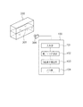
図1に、実施形態に係る液面形状の抽出装置100の機能構成を示す。
図1に示すように、透明なアクリル樹脂板等を用いて鋳型を模した容器200を作成し、溶鋼の代わりに水201を満たす。そして、容器200の一面に対向させるようにしてカメラ300を設置し、カメラ300により、容器200内の自由液面を撮影した時間的に連続する画像、ここでは動画像を取得する。カメラ300で撮影する画像は、可視光画像に限らず、赤外線画像等としてもよい。
Preferred embodiments of the present invention will be described below with reference to the accompanying drawings.
FIG. 1 shows a functional configuration of a liquid surface
As shown in FIG. 1, a
液面形状の抽出装置100において、101は入力部であり、カメラ300で撮影した容器200内の自由液面の動画像データを入力する。
In the liquid surface
102は原データ作成部であり、入力部101で入力する動画像データを用いて、各時間において一水平方向(以下、幅方向と呼ぶ)の各位置で液面高さが単一に定まる原データを作成する。原データは、各時刻での画像について、例えば高さ方向に微分フィルタ演算を行い、その輝度変化のピーク位置を液面と判定する手法で作成される。或いは、原データは、各時刻での画像について、例えば非特許文献2のように動的計画法により曲線を抽出する手法で作成される。
103は液面高さ推定部であり、原データ作成部102で作成した原データを対象として、原データと液面高さの計算値との差分に関する項と、液面高さの計算値の時間差分に関する項と、液面高さの計算値の空間差分に関する項とを含む評価関数を構築し、この評価関数を最小にする幅方向の各位置、各時刻の液面高さを推定する。
104は出力部であり、液面高さ推定部103で推定した液面高さから得られる液面形状の抽出結果を出力する。例えば液面形状の抽出結果を表示装置に表示したり、ネットワークを介して外部機器に送信したりする。
以下、実施形態における液面形状の抽出方法の詳細を説明する。
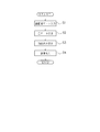
図2は、実施形態に係る液面形状の抽出装置100による液面形状の抽出方法を示すフローチャートである。
ステップS1で、入力部101は、カメラ300で撮影した容器200内の自由液面の動画像データを入力する。
Details of the liquid surface shape extraction method in the embodiment will be described below.
FIG. 2 is a flowchart illustrating a liquid surface shape extraction method performed by the liquid surface
In step S <b> 1, the
ステップS2で、原データ作成部102は、ステップS1で入力する動画像データを用いて原データを作成する。
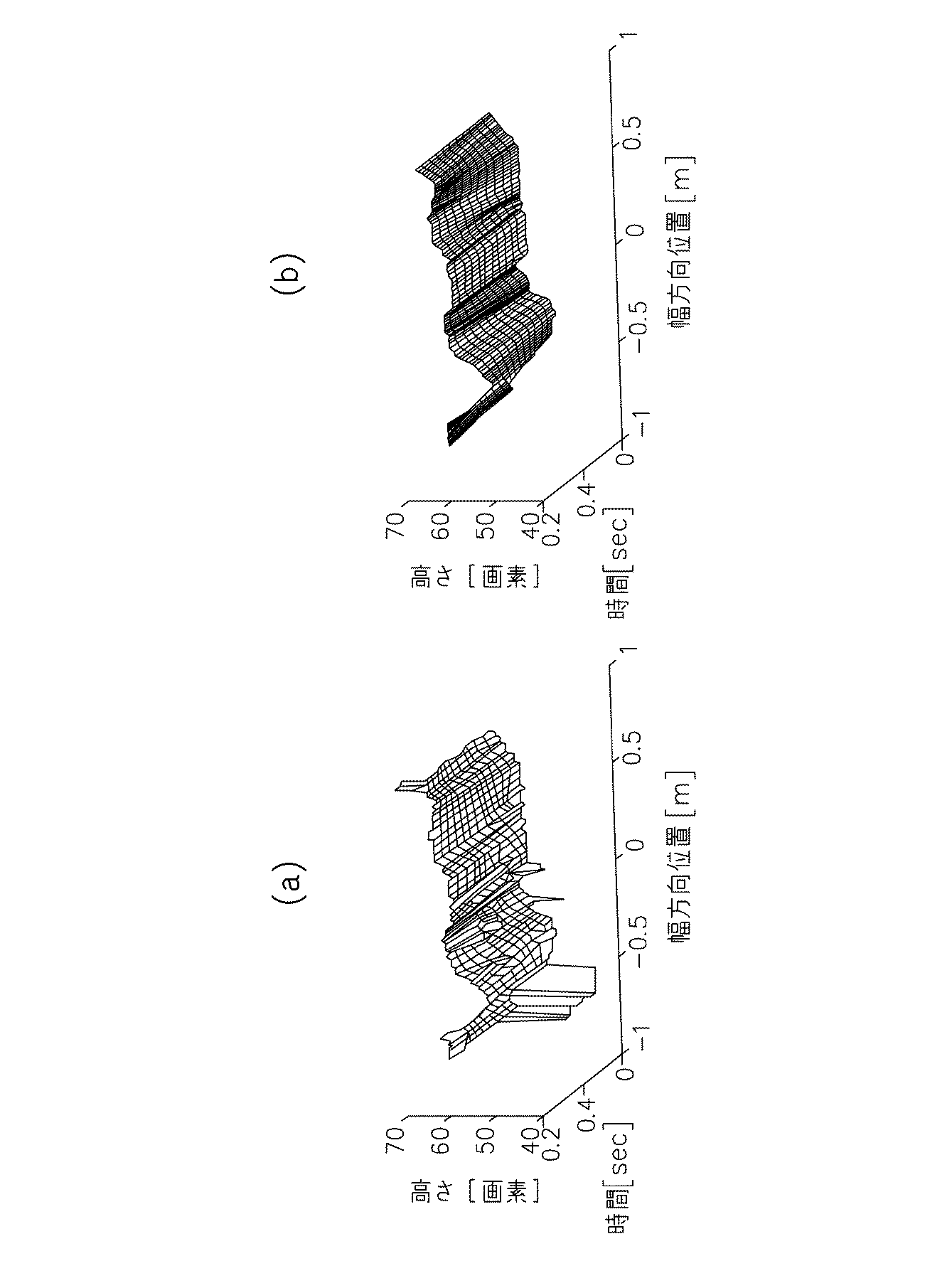
図3(a)に、非特許文献2のように動的計画法により曲線を抽出する手法(以下、単に動的計画法と呼ぶ)により作成した原データの例を示す。また、図4(a)に、ある時刻において、原データにおける液面形状401を原画像に重ね合わせて示す。
図4(a)に示すように、画像中のノイズに反応し、液面をなす曲線を誤識別することが原因で、幅方向の広い範囲(図中の左側の領域X)で液面の誤識別が生じている。このように広範囲に渡る誤識別は、空間方向のローパスフィルタ処理等で除去することが困難である。
In step S2, the original
FIG. 3A shows an example of original data created by a method of extracting a curve by dynamic programming (hereinafter simply referred to as dynamic programming) as in Non-Patent Document 2. FIG. 4A shows the
As shown in FIG. 4 (a), the liquid level in the wide range (region X on the left side in the figure) in response to noise in the image and misidentified the curve forming the liquid level. Misidentification has occurred. Such misidentification over a wide range is difficult to remove by a low-pass filter process or the like in the spatial direction.
ステップS3で、液面高さ推定部103は、ステップS2で作成した原データを対象として、原データと液面高さの計算値との差分に関する項と、液面高さの計算値の時間差分に関する項と、液面高さの計算値の空間差分に関する項との重み付き和として評価関数を構築し、この評価関数を最小にする幅方向の各位置、各時刻の液面高さを推定する。
具体的には、図3(a)、図4(a)のような原データを対象として、式(1)の評価関数を最小にする幅方向の各位置j(j=1、2、・・・、M)、各時刻t(t=1、2、・・・、T)の液面高さdj(t)を計算する。yj(t)は、原データにおける液面高さ(動的計画法により求めた液面高さ)である。
In step S3, the liquid
Specifically, for the original data as shown in FIGS. 3A and 4A, each position j in the width direction (j = 1, 2,...) That minimizes the evaluation function of Expression (1). .., M), and calculates the liquid level height d j (t) at each time t (t = 1, 2,..., T). y j (t) is the liquid level in the original data (the liquid level obtained by dynamic programming).
式(1)の第1項は液面高さの推定誤差を表わし、第2項は液面の時間方向変動のなめらかさに関する正則化項を表わし、第3項は液面の幅方向変動のなめらかさに関する正則化項を表わす。式(1)は、液面が時間方向及び空間方向にわたりなめらかに変化することを利用して、液面の時間及び空間変動のなめらかさの制約の下で、再構成誤差を最小化するものである。なお、λ1、λ2は推定値変動のなめらかさを制御する調整パラメータである。 The first term of equation (1) represents the estimation error of the liquid level, the second term represents a regularization term relating to the smoothness of the fluctuation in the time direction of the liquid level, and the third term represents the fluctuation in the width direction of the liquid level. Represents a regularization term for smoothness. Equation (1) uses the fact that the liquid level changes smoothly in the time direction and the spatial direction, and minimizes the reconstruction error under the restriction of the smoothness of the liquid level in time and space. is there. Note that λ 1 and λ 2 are adjustment parameters that control the smoothness of the estimated value fluctuation.
なお、第2項及び第3項のなめらかさに関する正則化項として、式(1)のような時間方向及び幅方向における液面高さの2階差分の二乗和でなく、式(2)のように、時間方向及び幅方向における液面高さの1階差分の二乗和としてもよい。 In addition, as a regularization term regarding the smoothness of the second term and the third term, not the sum of squares of the second-order difference of the liquid level height in the time direction and the width direction as in the equation (1), but in the equation (2) Thus, it is good also as the square sum of the 1st-floor difference of the liquid level height in a time direction and the width direction.
また、動的計画法により求めた液面高さyj(t)は、大きな外れ値を含む場合がある。このため、観測値とのあてはまりの尺度として二乗誤差{yj(t)−dj(t)}2を選んだ場合に、外れ値に推定結果が引きずられ過ぎるおそれがある。これを防ぐため、観測値とのあてはまりの尺度として、二乗誤差でなく誤差絶対値|yj(t)−dj(t)|を選ぶようにしてもよい。この考え方は、ロバスト統計学の分野においてL1損失最小化と呼ばれるものである(非特許文献3を参照)。この場合、式(3)の評価関数を最小にする液面高さdj(t)を計算する。 Further, the liquid level height y j (t) obtained by dynamic programming may include a large outlier. For this reason, when the square error {y j (t) −d j (t)} 2 is selected as a measure of the fit with the observed value, the estimation result may be excessively dragged to the outlier. In order to prevent this, an error absolute value | y j (t) −d j (t) | may be selected instead of the square error as a measure of the fit with the observed value. This idea is called L1 loss minimization in the field of robust statistics (see Non-Patent Document 3). In this case, the liquid level height d j (t) that minimizes the evaluation function of Equation (3) is calculated.
式(3)の数理計画問題は、スラック変数ξj(t)を追加し、式(4)のように書き換えることができる。この変換により、誤差絶対値の項を不等式制約に置き換えることができ、2次計画法を用いて解くことができる。 The mathematical programming problem of Equation (3) can be rewritten as Equation (4) by adding a slack variable ξ j (t). By this conversion, the term of error absolute value can be replaced by an inequality constraint and can be solved using quadratic programming.
図3(b)に、図3(a)の原データを対象として、式(4)の評価関数を2次計画法を用いて解いて得られた、液面形状の抽出結果(再構成結果)を示す。なお、M=176点、T=12フレーム(0.2sec間)とした。
図3(b)の再構成結果では、図3(a)の原データに含まれる異常値が除去され、時間方向及び空間方向になめらかに変動する液面形状を抽出できている。
なお、この計算にあたり、式(4)の調整パラメータはλ1=λ2=0.5とした。また、計算量低減のため、幅方向に関して10点間隔(約10mm間隔)に間引いて計算し、得られた計算結果を幅方向に補間し最終的な出力としている。
FIG. 3B shows a liquid surface shape extraction result (reconstruction result) obtained by solving the evaluation function of equation (4) using quadratic programming for the original data of FIG. ). Note that M = 176 points and T = 12 frames (between 0.2 sec).
In the reconstruction result of FIG. 3B, the abnormal value included in the original data of FIG. 3A is removed, and the liquid level shape that smoothly changes in the time direction and the spatial direction can be extracted.
In this calculation, the adjustment parameter of equation (4) is λ 1 = λ 2 = 0.5. Further, in order to reduce the amount of calculation, calculation is performed by thinning out at 10-point intervals (about 10 mm intervals) in the width direction, and the obtained calculation results are interpolated in the width direction to obtain a final output.
また、図4(b)に、図4(a)と同時刻(12フレーム中の3フレーム目)において、液面形状の再構成結果402を原画像に重ね合わせて示す。図4(b)に示すように、図4(a)で生じていた液面の誤識別が取り除かれ、なめらかな液面形状を抽出できていることがわかる。
FIG. 4B shows the
ステップS4で、出力部104は、ステップS3で推定した液面高さから得られる液面形状の抽出結果を出力する。出力部104から出力する液面形状の抽出結果としては、例えば図3(b)のようにグラフとして出力してもよいし、図4(b)のように原画像に液面形状の再構成結果402を重ね合わせて出力してもよいし、単に液面高さの値を出力するようにしてもよい。
In step S4, the
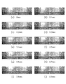
図5に、本発明を適用して液面形状を抽出した結果の例を表わす写真を示す。T=61フレーム(1.0sec間)とし、計算して得られた液面形状の再構成結果を原画像に重ね合わせた結果を6フレーム毎(0.1secピッチ)に10枚表示した例である。図5からもわかるように、時間方向及び空間方向になめらかに変動する液面形状を抽出できている。 FIG. 5 shows a photograph showing an example of the result of extracting the liquid surface shape by applying the present invention. In this example, T = 61 frames (for 1.0 sec), and the result of superimposing the liquid surface shape reconstruction result obtained by calculation on the original image is displayed every 6 frames (0.1 sec pitch). is there. As can be seen from FIG. 5, it is possible to extract a liquid level shape that smoothly varies in the time direction and the spatial direction.
以上述べたように、液面形状の変動は、幅方向、高さ方向及び時間方向の三次元空間においてなめらかな曲面を構成することを見出し、液面の誤識別を含む原データの異常値除去アルゴリズムを構築した。この異常値除去アルゴリズムにより、原データにおいて液面の誤識別が生じていても、その誤識別を取り除いて、時間方向及び空間方向になめらかに変動する液面形状を抽出することができる。
これにより、正確な液体の流動状況、液面挙動を把握することが可能となり、安価なコスト、簡易なセッティングで、連続鋳造機の鋳型を対象とする水モデル実験での水面高さの定量測定ができるようになる。この結果、実機では実施困難な各種実験を可能とし、良好な鋳片品質を可能とする操業因子を明らかにすることができる。
As described above, it has been found that the fluctuation of the liquid surface shape forms a smooth curved surface in the three-dimensional space in the width direction, the height direction, and the time direction, and the abnormal value removal of the original data including misidentification of the liquid surface is performed. An algorithm was constructed. With this abnormal value removal algorithm, even if a liquid level is erroneously identified in the original data, it is possible to remove the erroneous identification and extract a liquid level shape that varies smoothly in the time direction and the spatial direction.
This makes it possible to ascertain accurate fluid flow conditions and liquid level behavior. Quantitative measurement of water surface height in water model experiments for molds of continuous casting machines at low cost and simple settings. Will be able to. As a result, it is possible to perform various experiments that are difficult to carry out with an actual machine, and to clarify operational factors that enable good slab quality.
以上、本発明を種々の実施形態と共に説明したが、本発明はこれらの実施形態にのみ限定されるものではなく、発明の範囲内で変更等が可能である。例えば図1では、液面形状の抽出装置100において原データを作成するようにしたが、原データは外部で作成するようにして、液面形状の抽出装置100では、作成済みの原データを入力して、液面高さ推定部103で液面高さを推定する構成としてもよい。
As mentioned above, although this invention was demonstrated with various embodiment, this invention is not limited only to these embodiment, A change etc. are possible within the scope of the invention. For example, in FIG. 1, the original data is created by the liquid surface
また、本発明は、連続鋳造機の鋳型の水モデル実験に限定されるものではない。例えば電力会社における原油燃料タンクや原子炉溶融プール等におけるスロッシング現象解明を目的として水モデル実験が行われることがあり、このような場合においても本発明は適用可能である。また、容器200の形状は、用途に合わせたものとすればよい。
さらに、本発明は、水モデル実験に限定されるものではなく、一般に、誤差やノイズを含む動画像から、なめらかな変化を有する自由液面形状を抽出するのに適用可能である。
Further, the present invention is not limited to a water model experiment of a mold for a continuous casting machine. For example, a water model experiment may be performed for the purpose of elucidating the sloshing phenomenon in a crude oil fuel tank or a reactor molten pool in an electric power company, and the present invention can be applied even in such a case. Moreover, what is necessary is just to let the shape of the
Furthermore, the present invention is not limited to the water model experiment, and is generally applicable to extracting a free liquid surface shape having a smooth change from a moving image including errors and noises.
本発明を適用した液面形状の抽出装置は、例えばCPU、ROM、RAM等を備えたコンピュータ装置により実現される。
また、本発明は、本発明の機能を実現するソフトウェア(プログラム)を、ネットワーク又は各種記憶媒体を介してシステム或いは装置に供給し、そのシステム或いは装置のコンピュータがプログラムを読み出して実行することによっても実現可能である。
The liquid surface shape extraction apparatus to which the present invention is applied is realized by a computer apparatus including a CPU, a ROM, a RAM, and the like, for example.
The present invention also provides software (program) that implements the functions of the present invention to a system or apparatus via a network or various storage media, and the system or apparatus computer reads out and executes the program. It is feasible.
100:液面形状の抽出装置
101:入力部
102:原データ作成部
103:液面高さ推定部
104:出力部
200:容器
201:水
300:カメラ
DESCRIPTION OF SYMBOLS 100: Liquid surface shape extraction apparatus 101: Input part 102: Original data preparation part 103: Liquid level height estimation part 104: Output part 200: Container 201: Water 300: Camera
Claims (7)
前記時間的に連続する画像を用いて作成される、各時間において一水平方向の各位置で液面高さが単一に定まる原データを対象として、
前記原データと液面高さの計算値との差分に関する項と、液面高さの計算値の時間差分に関する項と、液面高さの計算値の空間差分に関する項とを含む評価関数に基づいて、前記一水平方向の各位置、各時刻の液面高さを推定することを特徴とする液面形状の抽出方法。 A liquid surface shape extraction method for extracting a liquid surface shape based on a plurality of temporally continuous images obtained by photographing a free liquid surface in a container,
For the original data that is created using the temporally continuous image and whose liquid level height is determined to be single at each position in one horizontal direction at each time,
An evaluation function including a term relating to the difference between the original data and the calculated liquid level height, a term relating to the time difference of the calculated liquid level height, and a term relating to the spatial difference in the calculated liquid level height. A liquid surface shape extraction method, wherein the liquid surface height at each position in the one horizontal direction and each time is estimated based on the liquid surface shape.
前記時間的に連続する画像を用いて作成される、各時間において一水平方向の各位置で液面高さが単一に定まる原データを対象として、
前記原データと液面高さの計算値との差分に関する項と、液面高さの計算値の時間差分に関する項と、液面高さの計算値の空間差分に関する項とを含む評価関数に基づいて、前記一水平方向の各位置、各時刻の液面高さを推定する推定手段を備えたことを特徴とする液面形状の抽出装置。 A liquid surface shape extraction device that extracts a liquid surface shape based on a plurality of temporally continuous images obtained by photographing a free liquid surface in a container,
For the original data that is created using the temporally continuous image and whose liquid level height is determined to be single at each position in one horizontal direction at each time,
An evaluation function including a term relating to the difference between the original data and the calculated liquid level height, a term relating to the time difference of the calculated liquid level height, and a term relating to the spatial difference in the calculated liquid level height. An apparatus for extracting a liquid level, comprising: estimation means for estimating the liquid level height at each position in the one horizontal direction and each time based on the above.
前記時間的に連続する画像を用いて作成される、各時間において一水平方向の各位置で液面高さが単一に定まる原データを対象として、
前記原データと液面高さの計算値との差分に関する項と、液面高さの計算値の時間差分に関する項と、液面高さの計算値の空間差分に関する項とを含む評価関数に基づいて、前記一水平方向の各位置、各時刻の液面高さを推定する処理をコンピュータに実行させるためのプログラム。 A program for extracting a liquid level shape based on a plurality of temporally continuous images obtained by photographing a free liquid level in a container,
For the original data that is created using the temporally continuous image and whose liquid level height is determined to be single at each position in one horizontal direction at each time,
An evaluation function including a term relating to the difference between the original data and the calculated liquid level height, a term relating to the time difference of the calculated liquid level height, and a term relating to the spatial difference in the calculated liquid level height. A program for causing a computer to execute a process for estimating the liquid level height at each position and each time in the one horizontal direction based on the program.
Priority Applications (1)
| Application Number | Priority Date | Filing Date | Title |
|---|---|---|---|
| JP2016137867A JP6759785B2 (en) | 2016-07-12 | 2016-07-12 | Liquid level shape extraction method, equipment and program |
Applications Claiming Priority (1)
| Application Number | Priority Date | Filing Date | Title |
|---|---|---|---|
| JP2016137867A JP6759785B2 (en) | 2016-07-12 | 2016-07-12 | Liquid level shape extraction method, equipment and program |
Publications (2)
| Publication Number | Publication Date |
|---|---|
| JP2018009847A true JP2018009847A (en) | 2018-01-18 |
| JP6759785B2 JP6759785B2 (en) | 2020-09-23 |
Family
ID=60995329
Family Applications (1)
| Application Number | Title | Priority Date | Filing Date |
|---|---|---|---|
| JP2016137867A Active JP6759785B2 (en) | 2016-07-12 | 2016-07-12 | Liquid level shape extraction method, equipment and program |
Country Status (1)
| Country | Link |
|---|---|
| JP (1) | JP6759785B2 (en) |
Cited By (3)
| Publication number | Priority date | Publication date | Assignee | Title |
|---|---|---|---|---|
| JP2019141895A (en) * | 2018-02-22 | 2019-08-29 | 日本製鉄株式会社 | State estimation method, molten metal surface control method, program, and state estimation apparatus |
| CN114707295A (en) * | 2022-02-23 | 2022-07-05 | 大连海事大学 | Method for calculating liquid level height of cabin in cargo ship stowage instrument |
| CN115439505A (en) * | 2022-08-29 | 2022-12-06 | 天津大学 | Two-dimensional fluid sloshing test data acquisition method based on image processing |
Citations (12)
| Publication number | Priority date | Publication date | Assignee | Title |
|---|---|---|---|---|
| JP2001041803A (en) * | 1999-08-04 | 2001-02-16 | Fujitsu Ltd | Liquid level detection method |
| US20040233783A1 (en) * | 2003-05-21 | 2004-11-25 | Siemens Milltronics Process Instruments Inc. | Method for echo processing in time-of-flight or level measurement systems |
| JP2005018521A (en) * | 2003-06-27 | 2005-01-20 | Sony Corp | Signal processing apparatus, signal processing method, program, and recording medium |
| JP2007078483A (en) * | 2005-09-13 | 2007-03-29 | Matsushita Electric Ind Co Ltd | Liquid level measuring method and liquid amount measuring method |
| JP2007085997A (en) * | 2005-09-26 | 2007-04-05 | Japan Atomic Energy Agency | Method for obtaining velocity distribution and pressure distribution in a fluid region whose surface shape changes over time |
| JP2008072636A (en) * | 2006-09-15 | 2008-03-27 | Nagaoka Univ Of Technology | Image processing system, image processing method, and program |
| US20080187219A1 (en) * | 2007-02-05 | 2008-08-07 | Chao-Ho Chen | Video Object Segmentation Method Applied for Rainy Situations |
| US20120136576A1 (en) * | 2010-11-30 | 2012-05-31 | Halliburton Energy Services, Inc. | Evaluating surface data |
| US20120281096A1 (en) * | 2011-05-02 | 2012-11-08 | Honeywell-Enraf B.V. | Storage tank inspection system and method |
| WO2013088827A1 (en) * | 2011-12-16 | 2013-06-20 | 旭硝子株式会社 | Video image analysis device, video image analysis method, and video image analysis program |
| JP2015507261A (en) * | 2011-12-21 | 2015-03-05 | ユニヴェルシテ・ピエール・エ・マリ・キュリ・(パリ・6) | Method for estimating optical flow based on asynchronous optical sensors |
| US20150276397A1 (en) * | 2012-08-27 | 2015-10-01 | Inb Vision Ag | Method and device for detecting deviations of an object surface |
-
2016
- 2016-07-12 JP JP2016137867A patent/JP6759785B2/en active Active
Patent Citations (12)
| Publication number | Priority date | Publication date | Assignee | Title |
|---|---|---|---|---|
| JP2001041803A (en) * | 1999-08-04 | 2001-02-16 | Fujitsu Ltd | Liquid level detection method |
| US20040233783A1 (en) * | 2003-05-21 | 2004-11-25 | Siemens Milltronics Process Instruments Inc. | Method for echo processing in time-of-flight or level measurement systems |
| JP2005018521A (en) * | 2003-06-27 | 2005-01-20 | Sony Corp | Signal processing apparatus, signal processing method, program, and recording medium |
| JP2007078483A (en) * | 2005-09-13 | 2007-03-29 | Matsushita Electric Ind Co Ltd | Liquid level measuring method and liquid amount measuring method |
| JP2007085997A (en) * | 2005-09-26 | 2007-04-05 | Japan Atomic Energy Agency | Method for obtaining velocity distribution and pressure distribution in a fluid region whose surface shape changes over time |
| JP2008072636A (en) * | 2006-09-15 | 2008-03-27 | Nagaoka Univ Of Technology | Image processing system, image processing method, and program |
| US20080187219A1 (en) * | 2007-02-05 | 2008-08-07 | Chao-Ho Chen | Video Object Segmentation Method Applied for Rainy Situations |
| US20120136576A1 (en) * | 2010-11-30 | 2012-05-31 | Halliburton Energy Services, Inc. | Evaluating surface data |
| US20120281096A1 (en) * | 2011-05-02 | 2012-11-08 | Honeywell-Enraf B.V. | Storage tank inspection system and method |
| WO2013088827A1 (en) * | 2011-12-16 | 2013-06-20 | 旭硝子株式会社 | Video image analysis device, video image analysis method, and video image analysis program |
| JP2015507261A (en) * | 2011-12-21 | 2015-03-05 | ユニヴェルシテ・ピエール・エ・マリ・キュリ・(パリ・6) | Method for estimating optical flow based on asynchronous optical sensors |
| US20150276397A1 (en) * | 2012-08-27 | 2015-10-01 | Inb Vision Ag | Method and device for detecting deviations of an object surface |
Non-Patent Citations (3)
| Title |
|---|
| 小川直子、南美穂子、渋谷政昭: "一次平滑化スプラインの平滑化行列の特性", 応用統計学, vol. 24巻1号, JPN6019044286, 20 November 1995 (1995-11-20), JP, pages 27 - 41, ISSN: 0004233127 * |
| 末吉俊幸: "最小絶対値法による回帰分析", JOURNAL OF THE OPERATIONS RESEARCH SOCIETY OF JAPAN, vol. 40巻2号, JPN6019044288, June 1997 (1997-06-01), JP, pages 261 - 275, ISSN: 0004233128 * |
| 椿涼太、藤田一郎: "ステレオ画像を利用した自由水面の水位分布計測法", 水工学論文集, vol. 48巻, JPN6020024964, 1 February 2004 (2004-02-01), JP, pages 523 - 528, ISSN: 0004319333 * |
Cited By (4)
| Publication number | Priority date | Publication date | Assignee | Title |
|---|---|---|---|---|
| JP2019141895A (en) * | 2018-02-22 | 2019-08-29 | 日本製鉄株式会社 | State estimation method, molten metal surface control method, program, and state estimation apparatus |
| CN114707295A (en) * | 2022-02-23 | 2022-07-05 | 大连海事大学 | Method for calculating liquid level height of cabin in cargo ship stowage instrument |
| CN114707295B (en) * | 2022-02-23 | 2025-02-18 | 大连海事大学 | A method for calculating the liquid level height of a tank in a liquid cargo ship stowage instrument |
| CN115439505A (en) * | 2022-08-29 | 2022-12-06 | 天津大学 | Two-dimensional fluid sloshing test data acquisition method based on image processing |
Also Published As
| Publication number | Publication date |
|---|---|
| JP6759785B2 (en) | 2020-09-23 |
Similar Documents
| Publication | Publication Date | Title |
|---|---|---|
| KR100326702B1 (en) | Method for calculating road width of the alarm device for lane beyond | |
| JP7120582B2 (en) | River flow velocity measurement device and method using optical flow image processing | |
| JP6737164B2 (en) | Liquid surface shape extraction method, device and program | |
| US9773302B2 (en) | Three-dimensional object model tagging | |
| Peter Heng et al. | Applying close range digital photogrammetry in soil erosion studies | |
| US10311591B2 (en) | Displacement detecting apparatus and displacement detecting method | |
| KR20210047955A (en) | Manufacturing condition output devices, quality management systems and programs | |
| JP6759785B2 (en) | Liquid level shape extraction method, equipment and program | |
| JP5957250B2 (en) | Crack detection method and crack display device | |
| KR20180040846A (en) | Setting method of edge blur for edge modeling | |
| Amaral et al. | Experimental methods for local-scale characterization of hydro-morphodynamic dam breach processes. Breach detection, 3D reconstruction, flow kinematics and spatial surface velocimetry | |
| JP2019503751A5 (en) | ||
| JP6278880B2 (en) | Water level measuring device | |
| Hassan et al. | A comparative study of techniques of distant reconstruction of displacement and strain fields using the DISTRESS simulator | |
| Camplani et al. | Accurate depth-color scene modeling for 3D contents generation with low cost depth cameras | |
| CN116433755B (en) | Structure dense displacement recognition method and system based on deformable three-dimensional model and optical flow representation learning | |
| Zappulla et al. | Visualization of Steel Continuous Casting Including a New Integral Method for Post‐Processing Temperature Data | |
| JP2021089185A (en) | Concrete structure diagnostic system, concrete structure diagnostic method, and program | |
| JP7398613B2 (en) | Joint surface roughness evaluation device and joint surface roughness evaluation system | |
| JP6525026B2 (en) | Method and apparatus for determining molten metal around pressure casting | |
| WO2024171873A1 (en) | Continuous casting system and melt level estimation method | |
| JP2015174116A (en) | Estimation method for shrinkage crack and memory medium for estimation program of the same | |
| JP6372217B2 (en) | Method and apparatus for estimating state of molten metal level in continuous casting mold | |
| JP6818263B2 (en) | Fracture surface analysis device and fracture surface analysis method | |
| CN119273653A (en) | Calculation method of piles subjected to wave loads based on machine vision |
Legal Events
| Date | Code | Title | Description |
|---|---|---|---|
| A621 | Written request for application examination |
Free format text: JAPANESE INTERMEDIATE CODE: A621 Effective date: 20190306 |
|
| A131 | Notification of reasons for refusal |
Free format text: JAPANESE INTERMEDIATE CODE: A131 Effective date: 20191119 |
|
| A02 | Decision of refusal |
Free format text: JAPANESE INTERMEDIATE CODE: A02 Effective date: 20200317 |
|
| A521 | Request for written amendment filed |
Free format text: JAPANESE INTERMEDIATE CODE: A523 Effective date: 20200528 |
|
| A911 | Transfer to examiner for re-examination before appeal (zenchi) |
Free format text: JAPANESE INTERMEDIATE CODE: A911 Effective date: 20200604 |
|
| TRDD | Decision of grant or rejection written | ||
| A01 | Written decision to grant a patent or to grant a registration (utility model) |
Free format text: JAPANESE INTERMEDIATE CODE: A01 Effective date: 20200804 |
|
| A61 | First payment of annual fees (during grant procedure) |
Free format text: JAPANESE INTERMEDIATE CODE: A61 Effective date: 20200817 |
|
| R151 | Written notification of patent or utility model registration |
Ref document number: 6759785 Country of ref document: JP Free format text: JAPANESE INTERMEDIATE CODE: R151 |