JP2018005259A - Control system - Google Patents
Control system Download PDFInfo
- Publication number
- JP2018005259A JP2018005259A JP2016126129A JP2016126129A JP2018005259A JP 2018005259 A JP2018005259 A JP 2018005259A JP 2016126129 A JP2016126129 A JP 2016126129A JP 2016126129 A JP2016126129 A JP 2016126129A JP 2018005259 A JP2018005259 A JP 2018005259A
- Authority
- JP
- Japan
- Prior art keywords
- periodic disturbance
- value
- controller
- frequency component
- torque
- Prior art date
- Legal status (The legal status is an assumption and is not a legal conclusion. Google has not performed a legal analysis and makes no representation as to the accuracy of the status listed.)
- Granted
Links
Images


Classifications
-
- G—PHYSICS
- G05—CONTROLLING; REGULATING
- G05B—CONTROL OR REGULATING SYSTEMS IN GENERAL; FUNCTIONAL ELEMENTS OF SUCH SYSTEMS; MONITORING OR TESTING ARRANGEMENTS FOR SUCH SYSTEMS OR ELEMENTS
- G05B23/00—Testing or monitoring of control systems or parts thereof
- G05B23/02—Electric testing or monitoring
- G05B23/0205—Electric testing or monitoring by means of a monitoring system capable of detecting and responding to faults
- G05B23/0218—Electric testing or monitoring by means of a monitoring system capable of detecting and responding to faults characterised by the fault detection method dealing with either existing or incipient faults
- G05B23/0224—Process history based detection method, e.g. whereby history implies the availability of large amounts of data
- G05B23/0227—Qualitative history assessment, whereby the type of data acted upon, e.g. waveforms, images or patterns, is not relevant, e.g. rule based assessment; if-then decisions
- G05B23/0235—Qualitative history assessment, whereby the type of data acted upon, e.g. waveforms, images or patterns, is not relevant, e.g. rule based assessment; if-then decisions based on a comparison with predetermined threshold or range, e.g. "classical methods", carried out during normal operation; threshold adaptation or choice; when or how to compare with the threshold
-
- G—PHYSICS
- G05—CONTROLLING; REGULATING
- G05B—CONTROL OR REGULATING SYSTEMS IN GENERAL; FUNCTIONAL ELEMENTS OF SUCH SYSTEMS; MONITORING OR TESTING ARRANGEMENTS FOR SUCH SYSTEMS OR ELEMENTS
- G05B13/00—Adaptive control systems, i.e. systems automatically adjusting themselves to have a performance which is optimum according to some preassigned criterion
- G05B13/02—Adaptive control systems, i.e. systems automatically adjusting themselves to have a performance which is optimum according to some preassigned criterion electric
- G05B13/04—Adaptive control systems, i.e. systems automatically adjusting themselves to have a performance which is optimum according to some preassigned criterion electric involving the use of models or simulators
- G05B13/042—Adaptive control systems, i.e. systems automatically adjusting themselves to have a performance which is optimum according to some preassigned criterion electric involving the use of models or simulators in which a parameter or coefficient is automatically adjusted to optimise the performance
-
- G—PHYSICS
- G05—CONTROLLING; REGULATING
- G05B—CONTROL OR REGULATING SYSTEMS IN GENERAL; FUNCTIONAL ELEMENTS OF SUCH SYSTEMS; MONITORING OR TESTING ARRANGEMENTS FOR SUCH SYSTEMS OR ELEMENTS
- G05B13/00—Adaptive control systems, i.e. systems automatically adjusting themselves to have a performance which is optimum according to some preassigned criterion
- G05B13/02—Adaptive control systems, i.e. systems automatically adjusting themselves to have a performance which is optimum according to some preassigned criterion electric
- G05B13/0205—Adaptive control systems, i.e. systems automatically adjusting themselves to have a performance which is optimum according to some preassigned criterion electric not using a model or a simulator of the controlled system
- G05B13/021—Adaptive control systems, i.e. systems automatically adjusting themselves to have a performance which is optimum according to some preassigned criterion electric not using a model or a simulator of the controlled system in which a variable is automatically adjusted to optimise the performance
- G05B13/022—Adaptive control systems, i.e. systems automatically adjusting themselves to have a performance which is optimum according to some preassigned criterion electric not using a model or a simulator of the controlled system in which a variable is automatically adjusted to optimise the performance using a perturbation of the variable
-
- G—PHYSICS
- G05—CONTROLLING; REGULATING
- G05B—CONTROL OR REGULATING SYSTEMS IN GENERAL; FUNCTIONAL ELEMENTS OF SUCH SYSTEMS; MONITORING OR TESTING ARRANGEMENTS FOR SUCH SYSTEMS OR ELEMENTS
- G05B19/00—Programme-control systems
- G05B19/02—Programme-control systems electric
- G05B19/18—Numerical control [NC], i.e. automatically operating machines, in particular machine tools, e.g. in a manufacturing environment, so as to execute positioning, movement or co-ordinated operations by means of programme data in numerical form
- G05B19/404—Numerical control [NC], i.e. automatically operating machines, in particular machine tools, e.g. in a manufacturing environment, so as to execute positioning, movement or co-ordinated operations by means of programme data in numerical form characterised by control arrangements for compensation, e.g. for backlash, overshoot, tool offset, tool wear, temperature, machine construction errors, load, inertia
Abstract
Description
本発明は、システムの共振・外乱を抑制しながら、周期的な外乱も同時に抑制する制御方式に関する。 The present invention relates to a control method that suppresses periodic disturbances at the same time while suppressing resonance and disturbances of the system.
特許文献1は、周期的な外乱を抑制する制御方式に関するものである。この特許文献1では、「周期外乱オブザーバ方式」によって、周期外乱である電動機のトルクリプルを抑制する手法が開示されている。
特許文献2,3は、μ設計法によるロバスト制御で、共振や外乱を抑制し、制御の安定化・高速化を実現するものである。特に、ダイナモメータ(エンジンベンチシステム)の動力計測装置の構成について記載されている。
本願発明は、システムの共振抑制と周期的な外乱抑制を同時に実現するものである。以下からは、ダイナモメータシステムのような多慣性系のモータドライブシステムを事例に挙げて説明するが、用途例はこれに限るものではない。例えば、電力系統システムならば、系統共振抑制と高調波抑制を同時に実現するなども該当する。 The present invention achieves simultaneous suppression of system resonance and periodic disturbance. In the following, a multi-inertia motor drive system such as a dynamometer system will be described as an example, but application examples are not limited thereto. For example, in the case of a power system, it is applicable to simultaneously realize system resonance suppression and harmonic suppression.
制御システムにおいて発生する共振や外乱は、制御性能を劣化させるのみでなく、システムを不安定化させる要因となる。構造・仕様・コスト等の制約があるため、システム共振や外乱を構造的対策によって十分に低減できない場合、共振抑制制御や外乱抑制制御が古くから行われている。 Resonance and disturbance generated in the control system not only deteriorate the control performance but also cause the system to become unstable. When system resonance and disturbance cannot be sufficiently reduced by structural measures due to restrictions on structure, specifications, cost, etc., resonance suppression control and disturbance suppression control have been performed for a long time.
外乱には、ホワイトノイズのように全周波数帯域で発生する「非周期外乱」と、特定の周波数成分で周期的に発生する「周期外乱」がある。例えば、モータであればトルクリプル、電力系統であれば高調波などが周期外乱に相当する。特に、周期外乱については特定周波数成分で繰り返し発生するため、システムの共振周波数と一致した場合、非常に大きな外乱として増幅され、システムの故障や不安定化に多大な影響を与える。 Disturbances include “non-periodic disturbances” that occur in the entire frequency band, such as white noise, and “periodic disturbances” that occur periodically at specific frequency components. For example, torque ripple corresponds to a periodic disturbance in the case of a motor, and harmonics in a power system correspond to a periodic disturbance. In particular, since periodic disturbances are repeatedly generated at a specific frequency component, when they coincide with the resonance frequency of the system, they are amplified as very large disturbances and have a great influence on system failure and instability.
外乱を抑制する一般的な手法として、外乱オブザーバが広く用いられている。外乱オブザーバは、指令値および制御対象モデルの逆特性から外乱を推定し、その推定外乱を指令値から差し引くことで外乱を除去する。 Disturbance observers are widely used as a general technique for suppressing disturbances. The disturbance observer estimates the disturbance from the command value and the inverse characteristic of the controlled object model, and removes the disturbance by subtracting the estimated disturbance from the command value.
しかしながら、制御対象モデルの逆特性は一般に微分要素を持つため、高周波帯域のゲイン増幅を防止して擬似微分とするためのローパスフィルタが用いられる。このローパスフィルタが存在するために、周波数帯域の外乱を推定・除去することができない問題を有する。 However, since the inverse characteristic of the controlled object model generally has a differential element, a low-pass filter for preventing gain amplification in the high frequency band and making it a pseudo differential is used. Since this low-pass filter exists, there is a problem that the disturbance in the frequency band cannot be estimated and removed.
例えば、3相モータのトルクリプルは、回転数に同期して発生する周期外乱であり、主に回転数の6×n倍で発生することが知られている。回転数が高くなるほどトルクリプルの周波数成分は高くなり、外乱オブザーバでは十分に抑制できない制御帯域となる。さらには、高周波数帯域にシステムの共振周波数がある場合は周期外乱が増幅し、非常に大きな振動・騒音が発生する。 For example, torque ripple of a three-phase motor is a periodic disturbance that occurs in synchronization with the rotational speed, and is known to occur mainly at 6 × n times the rotational speed. The higher the rotational speed, the higher the frequency component of torque ripple, resulting in a control band that cannot be sufficiently suppressed by a disturbance observer. Furthermore, when the system resonance frequency is in the high frequency band, the periodic disturbance is amplified, and very large vibrations and noises are generated.
特許文献1では、周期外乱の周期性に着目し、トルクリプル周波数に同期した回転座標系で外乱オブザーバを一般化した「周期外乱オブザーバ方式」が開示されている。
この方式は、特定周波数成分の周期外乱のみに寄与する制御系であり、制御対象の逆特性に微分特性を含まないため、高周波数帯域であっても周期外乱を抑制することができる。しかしながら、特定周波数成分以外の非周期外乱を抑制することはできない。したがって、例えばシステムの共振周波数と一致する非周期外乱が存在する場合は、その影響を除去できないため、非周期外乱を抑制する別の方策を併用する必要がある。 This method is a control system that contributes only to the periodic disturbance of the specific frequency component, and does not include a differential characteristic in the inverse characteristic of the controlled object, so that the periodic disturbance can be suppressed even in a high frequency band. However, non-periodic disturbances other than the specific frequency component cannot be suppressed. Therefore, for example, when there is an aperiodic disturbance that coincides with the resonance frequency of the system, the influence cannot be removed. Therefore, another measure for suppressing the aperiodic disturbance needs to be used in combination.
特許文献2,3では、共振/外乱抑制手法の一例として、μ設計法によるロバスト制御が用いられている。こうしたロバスト制御においては、システムの共振や外乱を包括的に抑制し、所望の指令値応答や外乱応答を実現するコントローラの設計を行う。
In
しかし、広範な周波数帯域で各種パラメータの摂動を考慮した場合、保守的な設計となりやすい。また、ボードの定理に従い、指令値応答や外乱応答の速応性と共振抑圧性能にはトレードオフがある。そのため、共振周波数付近の外乱応答特性が0dBを超えてしまい、そこに大きな周期外乱が含まれると十分に共振を抑制できないことがある。 However, when considering perturbations of various parameters in a wide frequency band, it tends to be a conservative design. Further, according to the board theorem, there is a trade-off between the rapid response of the command value response and the disturbance response and the resonance suppression performance. For this reason, the disturbance response characteristic near the resonance frequency exceeds 0 dB, and if a large period disturbance is included therein, the resonance may not be sufficiently suppressed.
以上示したように、制御システムにおいて、システムの制御性能を高度化するために、共振,非周期外乱,周期外乱をすべて抑制することが課題となる。 As described above, in the control system, in order to improve the control performance of the system, it is a problem to suppress all of resonance, non-periodic disturbance, and periodic disturbance.
本発明は、前記従来の問題に鑑み、案出されたもので、その一態様は、指令値と、制御対象システムの検出値と、制御対象システムの位相情報と、に基づいて、制御対象システムの操作量を決定するフィードバック制御器を備えた制御システムであって、前記フィードバック制御器は、前記検出値と前記位相情報とに基づいて、周期外乱補償信号を出力する周期外乱抑制制御器と、前記指令値と前記周期外乱補償信号とを加算した補正指令値と、前記検出値と、に基づいて、前記操作量を算出する共振・外乱抑制制御器と、を有し、前記周期外乱抑制制御器は一般化周期外乱オブザーバを用いることを特徴とする。 The present invention has been devised in view of the above-described conventional problems. One aspect of the present invention is based on a command value, a detection value of the control target system, and phase information of the control target system. A control system including a feedback controller for determining an operation amount of the periodic disturbance suppression controller that outputs a periodic disturbance compensation signal based on the detected value and the phase information; and A resonance / disturbance suppression controller that calculates the manipulated variable based on a correction command value obtained by adding the command value and the periodic disturbance compensation signal and the detected value; and the periodic disturbance suppression control The instrument is characterized by using a generalized periodic disturbance observer.
また、その一態様として、前記共振・外乱抑制制御器は、前記指令値がμ設計制御器の前記指令値から前記操作量までの伝達特性を介した出力と、前記検出値がμ設計制御器の前記検出値から前記操作量までの伝達特性を介した出力と、を加算して、前記操作量を出力するμ設計制御器を有し、前記周期外乱抑制制御器は、前記位相情報に抑制対象次数nを乗じたn次回転位相を用いて、前記検出値から周波数成分を抽出し、dnqn回転座標に変換した周期外乱のn次周波数成分ベクトルを出力する周波数成分抽出器と、前記n次回転位相を微分してn次回転周波数を算出する速度変換器と、前記周期外乱のn次周波数成分ベクトルに、前記n次回転周波数に同期した単一の周波数ベクトルが適用された逆モデルを乗じて、操作量推定値のn次周波数成分ベクトルを求める逆モデル乗算部と、前記操作量推定値のn次周波数成分ベクトルから、周期外乱補償値のn次周波数成分ベクトルが低域通過フィルタを介した値を減算して周期外乱推定値のn次周波数成分ベクトルを出力する第1減算器と、周期外乱指令値のn次周波数成分ベクトルから、前記周期外乱推定値のn次周波数成分ベクトルを減算して、周期外乱補償値のn次周波数成分ベクトルを出力する第2減算器と、前記周期外乱補償値のn次周波数成分ベクトルを、前記n次回転位相に基づいて、周期外乱に同期したdnqn回転座標系から元の時間波形に復元し、前記周期外乱補償信号を出力する補償信号合成部と、を備えたことを特徴とする。 Further, as one aspect thereof, the resonance / disturbance suppression controller is configured such that the command value is an output through the transfer characteristic from the command value to the manipulated variable of the μ design controller, and the detected value is the μ design controller. And an output via the transfer characteristic from the detected value to the manipulated variable, and a μ design controller that outputs the manipulated variable, and the periodic disturbance suppression controller suppresses the phase information. A frequency component extractor that extracts a frequency component from the detected value using an n-th order rotation phase multiplied by a target order n and outputs an n-th order frequency component vector of a periodic disturbance converted into d n q n rotation coordinates; A speed converter that differentiates the n-th order rotation phase to calculate an n-th order rotation frequency, and an inverse in which a single frequency vector synchronized with the n-th order rotation frequency is applied to the n-th order frequency component vector of the periodic disturbance. Multiply the model to calculate the manipulated variable estimate n Periodic disturbance estimation by subtracting the value of the nth-order frequency component vector of the periodic disturbance compensation value from the nth-order frequency component vector of the manipulated variable estimation value through the low-pass filter from the inverse model multiplication unit for obtaining the frequency component vector A first subtractor for outputting the n-th order frequency component vector of the value, and subtracting the n-th order frequency component vector of the estimated periodic disturbance value from the n-th order frequency component vector of the periodic disturbance command value to obtain the periodic disturbance compensation value n A second subtractor that outputs a second-order frequency component vector, and an n-th order frequency component vector of the periodic disturbance compensation value based on the n-th rotational phase from an original d n q n rotating coordinate system synchronized with the periodic disturbance. A compensation signal synthesizer that restores the time waveform and outputs the periodic disturbance compensation signal.
また、その一態様として、前記周波数成分抽出器に使用する前記検出値は、高域通過フィルタを通過させた値であることを特徴とする。 Further, as one aspect thereof, the detection value used for the frequency component extractor is a value that has passed through a high-pass filter.
また、その一態様として、前記共振・外乱抑制制御器は、前記指令値がμ設計制御器の前記指令値から前記操作量までの伝達特性を介した出力と、前記検出値が設計制御器の前記検出値から前記操作量までの伝達特性を介した出力と、を加算して、前記操作量を出力するμ設計制御器を有し、前記周期外乱抑制制御器は、前記位相情報に抑制対象次数nを乗じたn次回転位相を用いて、前記指令値から前記検出値を減算した偏差から周波数成分を抽出し、dnqn回転座標に変換した周期外乱のn次周波数成分ベクトルを出力する周波数成分抽出器と、前記n次回転位相を微分してn次回転周波数を算出する速度変換器と、周期外乱のn次周波数成分ベクトルに、前記n次回転周波数に同期した単一の周波数ベクトルが適用された逆モデルを乗じて、操作量推定値のn次周波数成分ベクトルを求める逆モデル乗算部と、前記操作量推定値のn次周波数成分ベクトルと、周期外乱補償値のn次周波数成分ベクトルが低域通過フィルタを介した値と、を加算して周期外乱補償値のn次周波数成分ベクトルを出力する加算器と、前記周期外乱補償値のn次周波数成分ベクトルを、前記n次回転位相に基づいて、周期外乱に同期したdnqn回転座標系から元の時間波形に復元し、前記周期外乱補償信号を出力する補償信号合成部と、を備えたことを特徴とする。 Further, as one aspect thereof, the resonance / disturbance suppression controller is configured such that the command value is an output through a transfer characteristic from the command value of the μ design controller to the manipulated variable, and the detected value is a value of the design controller. And a μ design controller that outputs the manipulated variable by adding the output via the transfer characteristic from the detected value to the manipulated variable, and the periodic disturbance suppression controller is subject to suppression in the phase information. using n-order rotational phase multiplied by the order n, the detected value to extract frequency components from the subtracted difference, d n q n outputs an n-order frequency component vector of the converted period disturbance rotating coordinate from said command value A frequency component extractor, a speed converter for differentiating the n-th order rotation phase to calculate an n-th order rotation frequency, and a single frequency synchronized with the n-th order rotation frequency in the n-th order frequency component vector of periodic disturbance Square inverse model with vector applied An inverse model multiplication unit for obtaining an n-order frequency component vector of the manipulated variable estimated value, an n-order frequency component vector of the manipulated variable estimated value, and an n-order frequency component vector of the periodic disturbance compensation value via a low-pass filter. And an adder that outputs an n-order frequency component vector of the periodic disturbance compensation value, and an n-order frequency component vector of the periodic disturbance compensation value is converted into a periodic disturbance based on the n-th rotation phase. And a compensation signal synthesizer that restores the original time waveform from the synchronized d n q n rotating coordinate system and outputs the periodic disturbance compensation signal.
また、その一態様として、前記共振・外乱抑制制御器は、前記指令値がμ設計制御器の前記指令値から前記操作量までの伝達特性を介した出力と、前記検出値がμ設計制御器の前記検出値から前記操作量までの伝達特性を介した出力と、を加算して、前記操作量を出力するμ設計制御器を有し、前記周期外乱抑制制御器は、前記位相情報に抑制対象次数nを乗じたn次回転位相を用いて、前記指令値から前記検出値を減算した偏差を、dnqn回転座標に変換した周期外乱のn次周波数成分ベクトルを出力する周波数成分変換器と、前記n次回転位相を微分してn次回転周波数を算出する速度変換器と、前記周期外乱のn次周波数成分ベクトルに、前記n次回転周波数に同期した単一の周波数ベクトルが適用された逆モデルを乗じて、操作量推定値のn次周波数成分ベクトルを求める逆モデル乗算部と、前記操作量推定値のn次周波数成分ベクトルを積分し、周期外乱補償値のn次周波数成分ベクトルを出力する積分器と、前記周期外乱補償値のn次周波数成分ベクトルを、前記n次回転位相に基づいて、周期外乱に同期したdnqn回転座標系から元の時間波形に復元し、前記周期外乱補償信号を出力する補償信号合成部と、を備えたことを特徴とする。 Further, as one aspect thereof, the resonance / disturbance suppression controller is configured such that the command value is an output through the transfer characteristic from the command value to the manipulated variable of the μ design controller, and the detected value is the μ design controller. And an output via the transfer characteristic from the detected value to the manipulated variable, and a μ design controller that outputs the manipulated variable, and the periodic disturbance suppression controller suppresses the phase information. Frequency component conversion that outputs an n-order frequency component vector of a periodic disturbance obtained by converting a deviation obtained by subtracting the detected value from the command value into d n q n rotation coordinates using an n-order rotation phase multiplied by the target order n A single frequency vector synchronized with the n-th order rotation frequency is applied to the n-th order frequency component vector of the periodic disturbance. By multiplying the inverse model An inverse model multiplication unit for obtaining an n-order frequency component vector of the value, an integrator for integrating the n-order frequency component vector of the manipulated variable estimation value and outputting an n-order frequency component vector of the periodic disturbance compensation value, and the periodic disturbance A compensation signal for restoring the n-th order frequency component vector of the compensation value to the original time waveform from the d n q n rotating coordinate system synchronized with the period disturbance based on the n-th order rotation phase and outputting the period disturbance compensation signal And a combining unit.
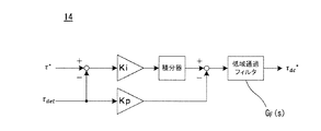
また、その一態様として、前記指令値と前記検出値に基づいて、直流トルク成分指令値を出力する低域トルク制御器を有し、前記直流トルク成分指令値と前記周期外乱補償信号を加算した値を前記補正指令値とし、前記低域トルク制御器は、PI制御器と、低域通過フィルタと、を備えたことを特徴とする。 In addition, as one aspect thereof, a low-frequency torque controller that outputs a DC torque component command value based on the command value and the detected value is provided, and the DC torque component command value and the periodic disturbance compensation signal are added. The correction command value is used as the value, and the low-frequency torque controller includes a PI controller and a low-pass filter.
また、その一態様として、抑制対象次数の異なる前記周期外乱抑制制御器を複数台有し、各々の前記周期外乱抑制制御器の出力を合算した値を周期外乱補償信号とすることを特徴とする。 Further, as one aspect thereof, there is provided a plurality of the periodic disturbance suppression controllers having different suppression target orders, and a value obtained by adding the outputs of the respective periodic disturbance suppression controllers is used as a periodic disturbance compensation signal. .
また、他の態様として、トルク指令値と、トルク検出値と、インバータによって駆動されるモータの位相情報と、に基づいて、前記インバータのインバータトルク指令値を演算するトルク制御器を備えた制御システムであって、前記トルク制御器は、前記トルク検出値と前記位相情報とに基づいて、周期外乱補償信号を出力する周期外乱抑制制御器と、前記トルク指令値と前記周期外乱補償信号とを加算した補正トルク指令値と、前記トルク検出値と、に基づいて、前記インバータトルク指令値を算出する共振・外乱抑制制御器と、を有し、前記周期外乱抑制制御器は一般化周期外乱オブザーバを用いることを特徴とする。 In another aspect, the control system includes a torque controller that calculates the inverter torque command value of the inverter based on the torque command value, the detected torque value, and the phase information of the motor driven by the inverter. The torque controller adds a periodic disturbance suppression controller that outputs a periodic disturbance compensation signal based on the torque detection value and the phase information, and adds the torque command value and the periodic disturbance compensation signal. A resonance / disturbance suppression controller that calculates the inverter torque command value based on the corrected torque command value and the detected torque value, and the periodic disturbance suppression controller includes a generalized periodic disturbance observer. It is characterized by using.
本発明によれば、制御システムにおいて、システムの制御性能を高度化するために、共振,非周期外乱,周期外乱をすべて抑制することが可能となる。 According to the present invention, it is possible to suppress all of resonance, non-periodic disturbance, and periodic disturbance in the control system in order to enhance the control performance of the system.
本明細書では、H∞的制御やμ設計法のように共振と非周期外乱を抑制する手法と、周期外乱オブザーバを用いた周期外乱抑制手法を併用する手段を説明する。 In this specification, a means for combining a technique for suppressing resonance and non-periodic disturbance, such as H∞ control and μ design method, and a technique for suppressing periodic disturbance using a periodic disturbance observer will be described.
本明細書では、共振抑制制御手法の一例としてμ設計法を用いて説明するが、共振比制御・H∞制御など、共振抑制手法を限定するものではなく、共振抑制後の閉ループ伝達特性が把握できれば、どのような方式にも対応できるものである。 In this specification, the μ design method is used as an example of the resonance suppression control method. However, the resonance suppression method such as resonance ratio control and H∞ control is not limited, and the closed-loop transfer characteristics after resonance suppression are understood. If possible, it can be applied to any method.
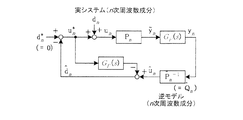
本願発明は、さまざまなシステムに適用可能な制御方式であるため、図1に示す一般的なフィードバック制御システムが基本構成図となる。指令値r*、検出値y、および、システムで問題となっている周期外乱を制御するために位相情報θをフィードバック制御器1に入力する。フィードバック制御器1で演算された操作量uは、制御対象システム2に入力される。
Since the present invention is a control method applicable to various systems, the general feedback control system shown in FIG. 1 is a basic configuration diagram. In order to control the command value r * , the detected value y, and the periodic disturbance which is a problem in the system, the phase information θ is input to the
実際の制御対象システム2では共振特性を有する場合があり、操作量uや検出値yには外乱が含まれる。また、外乱の中でもシステム特性に起因して周期的に発生する周期外乱は、制御性能や安定性に影響を与えやすい。
The actual
こうした周期外乱は、制御対象システム2の動作に伴って周期的に発生するものであるから、その周期性を検出するための位相情報θをフィードバック制御器1に返す。
Such a periodic disturbance is periodically generated in accordance with the operation of the
図2は、フィードバック制御器1の構成例である。共振・外乱抑制制御器3では後述する補正指令値rと検出値yに基づいてフィードバック制御を実施する。本願発明では、制御対象システム2に共振特性が含まれている場合を考慮し、共振抑制制御や外乱抑制制御も実施する。
FIG. 2 is a configuration example of the
例えば、PID制御器に外乱オブザーバ等を組み合わせたもの,共振比制御,H∞制御やμ設計等のロバスト制御などを想定しているが、これら共振抑制手法は限定されず、共振・外乱を抑制する任意の手法を用いれば良い。本願発明で重要となるのは、共振抑制した結果得られる指令値から検出値までの閉ループの周波数伝達特性となる。 For example, it is assumed that the PID controller is combined with a disturbance observer, resonance control, robust control such as H∞ control and μ design, etc., but these resonance suppression methods are not limited, and resonance and disturbance are suppressed. Any method may be used. What is important in the present invention is the closed-loop frequency transfer characteristic from the command value to the detection value obtained as a result of resonance suppression.
この共振抑制された閉ループ伝達特性を、後述する一般化周期外乱オブザーバのモデルに適用することが本願発明の主たる目的となる。 The main object of the present invention is to apply this resonance-suppressed closed-loop transmission characteristic to a model of a generalized periodic disturbance observer described later.
周期外乱抑制制御器4では、位相情報θを用いて検出値yに含まれる周期外乱を抽出し、その周期外乱を抑制するように周波数成分毎に制御する。その手法として、特許文献1等で提案されている一般化周期外乱オブザーバを用いる。仮に、特許文献1の手法のみを共振系システムに適用した場合、周期外乱は抑制できるが共振抑制や非周期的な外乱の抑制はできない。
The periodic
したがって、本願発明では共振抑制制御・非周期外乱抑制制御・周期外乱抑制制御を同時に実現する。周期外乱抑制制御器4で得られた周期外乱補償信号rpd *は、指令値r*に加算し、補正指令値rとして共振・外乱抑制制御器3に入力する。
Therefore, in the present invention, resonance suppression control, non-periodic disturbance suppression control, and periodic disturbance suppression control are simultaneously realized. The periodic disturbance compensation signal r pd * obtained by the periodic
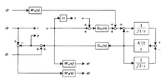
ここで、一般化周期外乱オブザーバについて簡単に説明する。図3は、一般化周期外乱オブザーバの基本構成例である。 Here, the generalized periodic disturbance observer will be briefly described. FIG. 3 is a basic configuration example of a generalized periodic disturbance observer.
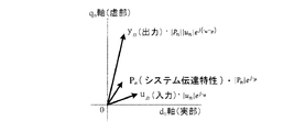
周期外乱は特定の周波数で発生する外乱であるため、その周波数成分を抽出して抑制制御系を構築する。ここで、n次周波数の周期外乱に同期したdnqn回転座標系を定義すると、図4に示すように、システム伝達特性Pnの入力信号(操作量)un、出力信号(検出値)ynとその間のシステム伝達特性Pnは1次元複素ベクトルで表現できる。(実部をdn軸,虚部をqn軸とする。)
システム伝達特性Pnは(1)式で示され、操作量uから検出値yまでのn次周波数成分の伝達特性を示している。したがって、例えばアクチュエータや負荷,センサ,無駄時間等の伝達特性をすべて包含した周波数伝達特性となり、n次周波数成分に限定すればシステム伝達特性Pnは1次元複素ベクトルで一般化できることを意味する。
Since the periodic disturbance is a disturbance generated at a specific frequency, a suppression control system is constructed by extracting the frequency component. Here, when defining the d n q n rotational coordinate system synchronized with the cycle disturbance of n order frequency, as shown in FIG. 4, the input signal (operation amount) of the system transfer characteristic P n u n, an output signal (detection value ) y n and between the system transfer characteristic P n can be represented by a 1-dimensional complex vector. (The real part is d n axis and the imaginary part is q n axis.)
The system transfer characteristic P n is expressed by equation (1) and indicates the transfer characteristic of the n-th order frequency component from the manipulated variable u to the detected value y. Therefore, for example, the frequency transfer characteristics include all of the transfer characteristics such as actuators, loads, sensors, dead time, and the like, meaning that the system transfer characteristics P n can be generalized by a one-dimensional complex vector if limited to n-order frequency components.

このように、特定周波数成分で一般化されたシステム上で制御を行うために、検出値yからdnqn回転座標系に同期した成分を抽出する。検出値yが単相信号の場合は、(2)式に基づいて抽出し、三相信号の場合は(3)式に基づいて抽出する。 Thus, in order to perform control on the system generalized with the specific frequency component, a component synchronized with the d n q n rotating coordinate system is extracted from the detected value y. When the detection value y is a single-phase signal, extraction is performed based on the equation (2), and when the detection value y is a three-phase signal, extraction is performed based on the equation (3).
GF(s)は、(2)式または(3)式でdnqn回転座標変換した後に、dn軸・qn軸成分を直流値として抽出するための低域通過フィルタであり、実部・虚部すなわちdn軸とqn軸それぞれに寄与する。例えば、フィルタ次数を1とした場合は、(4)式となる。 G F (s) is (2) after converting d n q n rotational coordinates by the formula or (3), a low-pass filter for extracting a d n axis · q n -axis component as a DC value, real and imaginary portion, that contribute to each d n-axis and q n axis. For example, when the filter order is 1, equation (4) is obtained.
ωf:ローパスフィルタのカットオフ周波数
こうして抽出された検出値ynに対し、(5)式に示すシステムの伝達特性Pnの逆モデルQn^を用いて、(6)式のように操作量unの操作量推定値un^を推定する。
ωf: Cut-off frequency of the low-pass filter With respect to the detected value y n extracted in this way, the manipulated variable is expressed as in equation (6) using the inverse model Q n ^ of the transfer characteristic P n of the system shown in equation (5). operation estimated value of u n u n ^ to estimate.
実際のシステムに入力される操作量unは、周期外乱dnを含んでいるため、(7)式に示すとおり(6)式の操作量推定値un^から低域通過フィルタGF(s)を介した操作量指令値un *を差し引くことで、周期外乱推定値dn^を推定する。 Manipulated variable u n to be input to the actual system, the period disturbance d for n contains, (7) the operation amount estimated value of expression as shown (6) u n ^ from the low-pass filter G F ( The periodic disturbance estimated value d n ^ is estimated by subtracting the manipulated variable command value u n * via s).
周期外乱指令値dn *(周期外乱を抑制する場合は0)から(7)式の周期外乱推定値dn^を差し引くことで、周期外乱dnを打ち消すことができる。以上、図3に基づいて一般化周期外乱オブザーバの動作を説明した。 By subtracting the periodic disturbance estimated value d n ^ in the equation (7) from the periodic disturbance command value d n * (0 when the periodic disturbance is suppressed), the periodic disturbance d n can be canceled out. The operation of the generalized periodic disturbance observer has been described above based on FIG.
ところで、(5)式で示した逆モデルQn^は、特定周波数についての単一の逆モデルであるため、複数の周波数成分で動作させる場合は、それぞれの周波数における逆モデルを用意しておく必要がある。例えば、動作周波数が可変なシステムでは、周期外乱の周波数も動作周波数のn倍で発生するため、抽出すべき周波数成分も可変となる。このような場合は、動作周波数の変化に応じて適用する逆モデルも変える必要がある。 By the way, since the inverse model Q n ^ shown in the equation (5) is a single inverse model for a specific frequency, when operating with a plurality of frequency components, an inverse model at each frequency is prepared. There is a need. For example, in a system in which the operating frequency is variable, the frequency of the periodic disturbance is also generated at n times the operating frequency, so that the frequency component to be extracted is also variable. In such a case, it is necessary to change the inverse model to be applied according to the change in the operating frequency.
例えば、周期外乱が取り得る周波数範囲を1〜1000Hzと設定し、1Hz毎に逆モデルQn^を用意する場合は、Qdn,Qqnをそれぞれ1000個実装しておき、動作周波数のn倍に同期した周波数成分を読み出すことで、変化する動作周波数にも対応できる。 For example, when the frequency range that can be taken by the periodic disturbance is set to 1 to 1000 Hz and an inverse model Q n ^ is prepared for every 1 Hz, 1000 Q dn and Q qn are respectively mounted and n times the operating frequency. By reading out the frequency component synchronized with the frequency, it is possible to cope with the changing operating frequency.
しかしながら、システム伝達特性Pnが共振系システムの場合は、逆モデルQn^も共振特性を含むため、動作周波数の変化に対して急峻なモデルの変化を引き起こす。特に、共振周波数が交差する際は、その位相特性が反転する場合がある。直ちに正確な逆モデルQn^を読み出すことができれば問題とはならないが、実際のコントローラはデジタル制御に伴う演算無駄時間や位相検出遅れがある。 However, when the system transfer characteristic P n is a resonance system, the inverse model Q n ^ also includes the resonance characteristic, which causes a steep model change with respect to a change in operating frequency. In particular, when the resonance frequencies intersect, the phase characteristics may be reversed. If an accurate inverse model Q n ^ can be read out immediately, there is no problem, but an actual controller has calculation dead time and phase detection delay associated with digital control.
また、一般化周期外乱オブザーバは低域通過フィルタGF(s)によって決定づけられる閉ループ特性による応答遅れが生じ、モデル化誤差によって共振周波数のズレがあると最悪の場合、逆位相で補償する状態に陥り、制御が不安定となる恐れがある。したがって、周波数変化に対して逆モデルが急峻な特性変化を持つ場合は、不安定化を防止する対策が必須である。 Further, the generalized periodic disturbance observer has a response delay due to the closed loop characteristic determined by the low-pass filter G F (s), and if there is a resonance frequency shift due to a modeling error, in the worst case, it is in a state of compensating with an opposite phase. There is a risk that control will become unstable. Therefore, when the inverse model has a steep characteristic change with respect to the frequency change, a measure for preventing instability is essential.
本願発明では、この逆モデルQn^の急峻な変化を抑えるために、共振抑制制御をマイナーループで実施した上で、共振抑制制御特性を含んだシステムの閉ループ伝達特性で逆モデルQn^を生成し、それを一般化周期外乱オブザーバに適用するものである。さらには、共振と非周期的な外乱をも抑制した上で、周期的な外乱を抑制するため、特許文献1〜3にはなかった「共振」,「非周期外乱」,「周期外乱」のすべての課題を同時に改善することが可能となる。
In the present invention, in order to suppress the abrupt change of the inverse model Q n ^, the resonance suppression control is performed in the minor loop, and then the inverse model Q n ^ is set to the closed loop transmission characteristic of the system including the resonance suppression control characteristic. Generated and applied to a generalized periodic disturbance observer. Furthermore, in order to suppress periodic disturbances while also suppressing resonance and non-periodic disturbances, there are “resonance”, “non-periodic disturbances”, and “periodic disturbances” that were not found in
以下、実施形態のひとつとして、モータドライブ用途の2慣性共振系システムにおけるトルクフィードバック制御を例に挙げて説明する。 Hereinafter, as one embodiment, torque feedback control in a two-inertia resonance system for motor drive will be described as an example.
なお、3慣性系以上の多慣性系や、モータドライブシステム以外の共振系システムの用途であっても、本願発明の手法が適用可能である。また、トルク制御以外(例えば、速度制御,位置制御,加速度制御,電流制御など)であっても同様の制御構成で実現可能であり、フィードバック制御システムにおける指令値と検出値の種目を限定するものではない。 Note that the technique of the present invention can be applied to a multi-inertia system having three or more inertia systems or a resonance system other than a motor drive system. Moreover, even if it is other than torque control (for example, speed control, position control, acceleration control, current control, etc.), it can be realized with the same control configuration, and the types of command values and detection values in the feedback control system are limited. is not.
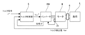
図5に、本願発明の効果を説明するための代表例として、2慣性共振系のモータドライブシステムでトルク制御を実現するための構成図を示す。 FIG. 5 shows a configuration diagram for realizing torque control in a two-inertia resonance motor drive system as a representative example for explaining the effect of the present invention.
装置構成の一例として、モータMと負荷Lによる2慣性系システムを想定する。結合軸にはトルクメータ6を設置し、トルク検出値τdetをトルク制御器5にフィードバックする。モータMを駆動するインバータINVでは,回転位置センサ21あるいはセンサレス制御等で得られたモータMの位相情報θないし回転速度情報などを取得し、トルク制御器5にその情報を渡す。
As an example of the device configuration, a two-inertia system using a motor M and a load L is assumed. A
トルク制御器5はトルク指令値τ*,位相情報θ,トルク検出値τdetに基づいて、インバータトルク指令値τinv *を演算する。インバータINVはインバータトルク指令値τinv *に基づいて所望の電圧をモータMへ印加することでモータMを制御し、モータMは負荷Lを駆動する。
The
位相情報θや回転速度情報は、後述する周期外乱抑制制御(本例ではトルクリプル抑制制御に相当)のために用いられる。 The phase information θ and the rotation speed information are used for periodic disturbance suppression control (corresponding to torque ripple suppression control in this example), which will be described later.
トルク検出値τdetを、速度検出・位置検出・電流検出などに置き換えて、各々に合わせて指令値を変更しても、同様のフィードバック制御システムが成り立つ。 Even if the torque detection value τ det is replaced with speed detection, position detection, current detection, and the like, and the command value is changed according to each, the same feedback control system is established.
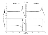
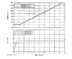
また、本願発明を説明するにあたり、数値例として本構成のシステム伝達特性を図6に示す。図6は、トルク制御を実施しない場合のシステムの開ループ伝達特性であり、インバータトルク指令値τinv *からトルク検出値τdetまでの周波数特性を示している。低周波数帯域ではトルク誤差(指令値から検出値のゲイン(振幅)特性が0dBとならない)があり、高域では2慣性共振系による共振点が存在する。また、図6の周波数特性は外乱を含んでいないが、実際のトルク検出値τdetには、例えばトルクリプルのような周期外乱や、ホワイトノイズ等の非周期外乱が含まれることにも留意する。こうした外乱は,特に図6に示した共振点で増幅し、トルク検出値τdetに顕著にその影響が現れる。 In describing the present invention, the system transfer characteristic of this configuration is shown in FIG. 6 as a numerical example. FIG. 6 shows the open loop transmission characteristic of the system when torque control is not performed, and shows the frequency characteristic from the inverter torque command value τ inv * to the torque detection value τ det . There is a torque error (the gain (amplitude) characteristic of the detected value from the command value does not become 0 dB) in the low frequency band, and a resonance point due to the two-inertia resonance system exists in the high frequency band. Moreover, although the frequency characteristic of FIG. 6 does not include disturbance, it is also noted that the actual torque detection value τ det includes periodic disturbance such as torque ripple and non-periodic disturbance such as white noise. Such a disturbance is amplified particularly at the resonance point shown in FIG. 6, and its influence appears remarkably in the torque detection value τ det .
図7は、図6の特性においてトルクフィードバック制御を行わない場合の回転数とトルクの波形例である。図7では、0.5seconds以降のトルク指令値τ*は一定値(5[Nm])である。 FIG. 7 is a waveform example of the rotational speed and torque when the torque feedback control is not performed in the characteristics of FIG. In FIG. 7, the torque command value τ * after 0.5 seconds is a constant value (5 [Nm]).
図7に示すように、トルク誤差や外乱が発生しており、回転数上昇中にトルクリプル周波数とシステムの共振周波数が一致したとき、特に大きな共振現象が発生していることが分かる。 As shown in FIG. 7, a torque error or disturbance occurs, and it can be seen that a particularly large resonance phenomenon occurs when the torque ripple frequency and the resonance frequency of the system coincide with each other while the rotational speed increases.
本願発明は、図6における低域のゲイン特性を0dBとしてトルク誤差をなくし、かつ、高域の共振を抑制して非周期外乱と周期外乱をも同時に抑制することを目的とする。 The object of the present invention is to eliminate the torque error by setting the low-frequency gain characteristic in FIG. 6 to 0 dB, and to suppress the high-frequency resonance and simultaneously suppress the non-periodic disturbance and the periodic disturbance.
[実施形態1]
図8に本実施形態1の制御システムとしてトルク制御器を示す。
[Embodiment 1]
FIG. 8 shows a torque controller as the control system of the first embodiment.
〔第1の機能:共振および非周期外乱抑制制御器7〕
共振および非周期外乱抑制制御器7は図2の共振・外乱抑制制御器3に対応する。
[First Function: Resonance and Aperiodic Disturbance Suppression Controller 7]
The resonance and non-periodic
本実施形態1では、構造化特異値μを用いたμ設計による共振抑制および非周期外乱抑制を実装する例で説明する。H∞制御,共振比制御など,そのほかの共振抑制手法を用いても同様に実現できることを示唆しておく。 In the first embodiment, an example in which resonance suppression and aperiodic disturbance suppression by μ design using a structured singular value μ is implemented will be described. It is suggested that other resonance suppression methods such as H∞ control and resonance ratio control can be used in the same way.
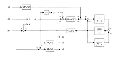
図9は、μ設計で用いる一般化プラントの構成例である。機械系パラメータ等の摂動を個別に考慮しても良いが、実用上は物理モデル(バネ・マス要素)を明示的に同定することを省略し、トルク入出力の周波数伝達特性から簡易的に同定することが多い。したがって、ここではインバータから入力される定常トルク誤差(トルク偏差)Δτを摂動項として見積もり、ロバスト制御性能を担保する手法を用いる。 FIG. 9 is a configuration example of a generalized plant used in μ design. Perturbations such as mechanical parameters may be considered individually, but in practice, the physical model (spring / mass element) is not explicitly identified and is simply identified from the frequency transfer characteristics of torque input / output Often to do. Therefore, here, a steady torque error (torque deviation) Δτ input from the inverter is estimated as a perturbation term, and a method of ensuring robust control performance is used.
図9の符号は以下の通りである。
J1:モータの慣性モーメント,J2:負荷の慣性モーメント,K12:軸ねじれ剛性,s:ラプラス演算子,Δτ:定常トルク誤差(トルク偏差),Gtm(s):トルクメータ等の検出応答伝達関数,Ginv:インバータ応答伝達関数,d1:外乱(周期外乱を含む),d2およびr:μ設計制御器入力,d3:トルク検出ノイズ,z:定常トルク誤差の評価出力,w:定常トルク誤差による外乱入力,u:μ設計制御器出力(操作量),y:観測出力(検出値),e1:インバータトルク指令の評価出力,e2:トルク偏差の評価出力,Wn(s):外乱d1に対する重み関数,Wu(s):インバータトルク指令に対する重み関数,We(s):トルク偏差に対する重み関数。
The symbols in FIG. 9 are as follows.
J1: Motor inertia moment, J2: Load inertia moment, K12: Shaft torsional rigidity, s: Laplace operator, Δτ: Steady torque error (torque deviation), G tm (s): Detection response transfer function of torque meter, etc. , G inv : Inverter response transfer function, d1: Disturbance (including periodic disturbance), d2 and r: μ design controller input, d3: Torque detection noise, z: Steady torque error evaluation output, w: Steady torque error Disturbance input, u: μ design controller output (operation amount), y: observation output (detected value), e1: inverter torque command evaluation output, e2: torque deviation evaluation output, W n (s): disturbance d1 Weight function, W u (s): Weight function for inverter torque command, W e (s): Weight function for torque deviation.
トルク偏差に対する重み関数We(s)は、低域の定常偏差をなくすように重みづけをしている。インバータトルク指令に対する重み関数Wu(s)は、インバータトルクの高周波特性を低減するように設定している。外乱d1に対する重み関数Wn(s)は、周期外乱や非周期的外乱の抑圧性能を向上するように重み付けしている。 Weight function W e with respect to the torque deviation (s) is a weighted to eliminate the steady state error of the low frequency range. The weight function W u (s) for the inverter torque command is set so as to reduce the high-frequency characteristic of the inverter torque. The weighting function W n (s) for the disturbance d1 is weighted so as to improve the suppression performance of periodic disturbances and aperiodic disturbances.
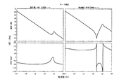
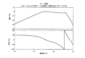
図9のように構成した一般化プラントにおいて、D−Kイテレーションを実施して得られたμ設計制御器の特性を図10に示す。上段はゲイン線図,下段は位相線図を示している。左側はμ設計制御器の指令値rから操作量uの伝達特性Cref(s),右側はμ設計制御器の検出値yから操作量uの伝達特性Ctm(s)を示している。 FIG. 10 shows the characteristics of the μ design controller obtained by performing the DK iteration in the generalized plant configured as shown in FIG. The upper diagram shows the gain diagram, and the lower diagram shows the phase diagram. The left side shows the transfer characteristic Cref (s) of the manipulated variable u from the command value r of the μ design controller, and the right side shows the transfer characteristic Ctm (s) of the manipulated variable u from the detected value y of the μ design controller.
上記で設計された伝達特性Cref(s)と伝達特性Ctm(s)を持つμ設計制御器は、図8の共振および非周期外乱抑制制御器7に実装され、図11に示すように構成される。補正トルク指令値τr *が伝達特性Cref(s)を介した出力と、トルク検出値τdetが伝達特性Ctm(s)を介した出力と、を加算してインバータトルク指令値τinv *を生成する。
The μ design controller having the transfer characteristic Cref (s) and the transfer characteristic Ctm (s) designed as described above is mounted on the resonance and non-periodic
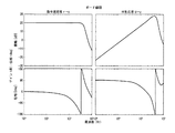
共振および非周期外乱抑制制御器7のみを機能させた場合の閉ループ伝達特性を図12に示す。また、そのときのトルク波形例を図13に示す。図12の上段はゲイン線図,下段は位相線図を示している。左側はトルク指令値τ*からトルク検出値τdetまでの閉ループ特性(指令値応答),右側は外乱d1からトルク検出値τdetまでの閉ループ特性(外乱応答)を示している。
FIG. 12 shows closed loop transfer characteristics when only the resonance and non-periodic
図7の制御なしの場合のトルク波形と比較すると、図13のトルク波形は共振および非周期外乱抑制制御器7の効果により、共振現象を大幅に低減できていることが分かる。しかしながら、図12の外乱特性を見て分かるように、共振周波数付近の外乱に対する閉ループ伝達特性は0dBを超えているため、周期的な外乱に対してはリプルが残留し、十分に除去できているとは言えない。本実施形態1で用いたμ設計手法に関わらず、全周波数帯域で制御設計するコントローラは、ボードの定理に従って、どこかの周波数帯域を低減すれば、そのほかの周波数帯域が増幅される。
Compared to the torque waveform in the case of no control in FIG. 7, it can be seen that the torque waveform in FIG. 13 can greatly reduce the resonance phenomenon due to the effect of the resonance and non-periodic
したがって、設計の善し悪しに関わらず、指令値応答と外乱抑圧に関する速応性と抑圧振幅にはトレードオフが発生する。 Therefore, regardless of whether the design is good or bad, there is a trade-off between the speed response and the suppression amplitude related to the command value response and the disturbance suppression.
そこで、本実施形態1では、上述のような共振および非周期外乱抑制制御器7に加えて、第2の機能として特定の周波数成分のみに寄与する周期外乱オブザーバによる周期外乱抑制制御器8を組み合わせる。
Thus, in the first embodiment, in addition to the resonance and non-periodic
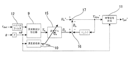
〔第2の機能:周期外乱抑制制御器8〕
図14は、図8の周期外乱抑制制御器8の構成図である。図3で前述した一般化周期外乱オブザーバを用いている。図14の符号は以下の通りである。
Tn:周期外乱(トルクリプル)のn次周波数成分ベクトル,Un^:操作量推定値のn次周波数成分ベクトル(周期外乱を含む推定値),Dn *:周期外乱指令値のn次周波数成分ベクトル(抑制する場合は通常ゼロ),Dn^:周期外乱推定値のn次周波数成分ベクトル,TPDn *:周期外乱補償値のn次周波数成分ベクトル。
[Second function: Periodic disturbance suppression controller 8]
FIG. 14 is a block diagram of the periodic
T n : n-order frequency component vector of periodic disturbance (torque ripple), U n ^: n-order frequency component vector of operation amount estimated value (estimated value including periodic disturbance), D n * : n-order frequency of periodic disturbance command value Component vector (usually zero for suppression), D n ^: n-order frequency component vector of the periodic disturbance estimated value, T PDn * : n-order frequency component vector of the periodic disturbance compensation value.
まず、周波数成分抽出器9では、位相情報θに対して周期外乱(トルクリプル)の抑制対象次数nを乗じたn次回転位相nθを用いて、トルク検出値τdetから周波数成分を抽出し、トルクリプルに同期したdnqn回転座標系の周期外乱(トルクリプル)のn次周波数成分ベクトルTnに変換する。周期外乱のn次周波数成分ベクトルTnの変換式は(2)式に基づき以下の(8)式となる。
First, the
速度変換器10では、n次回転位相nθを微分してn次回転周波数n・ωmを算出する。次に、逆モデル乗算部15において、(8)式で算出した周期外乱のn次周波数成分ベクトルTnに、逆モデルQn^を乗じて操作量推定値のn次周波数成分ベクトルUn^を求める。なお、(5)式に逆モデルQn^の算出式がある。この際、逆モデルQn^にはn次回転周波数n・ωmに同期した単一の周波数成分ベクトルが適用される。前述したとおり、逆モデルQn^には、第1の機能である「共振および非周期外乱抑制制御器7」の閉ループ伝達特性(すなわち、図12の指令値応答:トルク指令値からトルク検出までの周波数伝達特性)をマイナーループ特性として適用するため、図6のような共振特性は含まれず、動作周波数の変化、すなわち可変速運転に対して比較的ロバストな制御系を構築することができる。
The
操作量推定値のn次周波数成分ベクトルUn^には周期外乱が含まれているため、操作量推定値のn次周波数成分ベクトルUn^から、周期外乱補償値のn次周波数成分ベクトルTpDn *が低域通過フィルタGF(s)を通った値を差し引き、周期外乱推定値のn次周波数成分ベクトルDn^を推定する。なお、低域通過フィルタGF(s)を介するのは、周波数成分抽出器9に含まれる低域通過フィルタGF(s)の応答と合わせるためである。周期外乱指令値のn次周波数成分ベクトルDn *から推定した周期外乱推定値のn次周波数成分ベクトルDn^を減算し、周期外乱補償値のn次周波数成分ベクトルTpDn *を算出することで、周期外乱を抑制できる。なお、フィルタ次数を1とした場合の低域通過フィルタGF(s)は(4)式となる。
Since the n-th order frequency component vector U n ^ of the manipulated variable estimated value includes a periodic disturbance, the n-order frequency component vector T of the periodic disturbance compensation value is derived from the n-order frequency component vector U n ^ of the manipulated variable estimated value. The value obtained by passing pDn * through the low-pass filter G F (s) is subtracted to estimate the nth-order frequency component vector D n ^ of the periodic disturbance estimated value. Incidentally, through the low-pass filter G F (s) is to match the response of the low pass filter G F (s) included in the
こうして生成した周期外乱補償値のn次周波数成分ベクトルTpDn *は、補償信号合成部11において、(9)式に基づいて周期外乱に同期したdnqn回転座標系から元の時間波形に復元する。なお、nに複数の次数を設定して並列に構成することも可能であり、これら各次数の周波数成分を合算することにより、周期外乱補償信号τpd *が合成できる。
Thus resulting periodic disturbance compensation value of n order frequency component vector T PDN * is the compensation
以上より周期外乱抑制制御器4を構成し、その出力である周期外乱補償信号τpd *を図8におけるトルク指令値τ*に加算することで、共振および非周期外乱抑制制御器7の新たな入力となる補正トルク指令値τr *を生成する。これにより、第1の機能である共振および非周期外乱抑制制御に加え、周期外乱抑制を同時に実現することができる。
As described above, the periodic
図15に、図8の構成で共振・非周期外乱・周期外乱を同時に抑制した場合のトルク波形例を示す。 FIG. 15 shows an example of a torque waveform when resonance, non-periodic disturbance, and periodic disturbance are simultaneously suppressed with the configuration of FIG.
共振と非周期外乱のみを抑制した場合の図13と比較し、残留していた周期外乱の影響も除去され、トルクリプルや共振現象がさらに低減できていることが分かる。したがって、数値演算からも本実施形態1の効果が確認できる。 Compared with FIG. 13 in which only resonance and non-periodic disturbance are suppressed, it can be seen that the influence of the remaining periodic disturbance is also eliminated, and torque ripple and resonance phenomenon can be further reduced. Therefore, the effect of the first embodiment can also be confirmed from numerical calculation.
本実施形態1では、共振と非周期外乱と周期外乱を同時に抑制することができる。また本制御方法をモータドライブシステムのトルク制御に適用した場合、トルク制御の精度を向上させることができる。 In the first embodiment, resonance, non-periodic disturbance, and periodic disturbance can be suppressed simultaneously. When this control method is applied to torque control of a motor drive system, the accuracy of torque control can be improved.
[実施形態2]
実施形態1において(8)式によってトルク検出値τdetから周期外乱成分を抽出する際、トルク検出値τdetに含まれるTdncosnq+Tqnsinnqに着目すると、その周波数成分においては(10)式のように展開される。
[Embodiment 2]
In
(10)式におけるTdncos2nθ+Tqnsin2nθ、Tqncos2nθ+Tdnsin2nθで発生している2n倍の周波数成分を、低域通過フィルタGF(s)によって除去することにより、dnqn回転座標系で使用するn次周波数成分のTdnおよびTqnを抽出できる。 T dn cos2nθ + T qn sin2nθ in (10), the T qn cos2nθ + T dn 2n times the frequency components occurring in Sin2enushita, are removed by the low-pass filter G F (s), d n q n rotating coordinate system T dn and T qn of the n-th order frequency component used in FIG.
一方、トルク検出値τdetに直流トルク成分Tdcが含まれる場合は、以下の(11)式のように展開される。 On the other hand, when the DC torque component Tdc is included in the torque detection value τ det , it is developed as in the following equation (11).
(11)式のTdncos2nθ+Tqnsin2nθ+2Tdccosnθ、Tqncos2nθ+Tdnsin2nθ+2Tdcsinnθを(10)式と比較すると、(10)式で発生していた2n倍周波数成分に加えて、直流トルク成分Tdcに関する1n倍成分が発生することが分かる。同様に、低域通過フィルタGF(s)で除去しても良いが、2n倍成分のみの場合に比べて、1n倍成分は低周波数となり、低域通過フィルタGF(s)で除去するためにはカットオフ周波数をより低く設計する必要がある。 When comparing T dn cos2nθ + T qn sin2nθ + 2T dc cosnθ, T qn cos2nθ + T dn sin2nθ + 2T dc sinnθ in the equation (11) with the equation (10), the DC torque component Tdc It can be seen that a 1n-fold component is generated. Similarly, it may be removed by the low-pass filter G F (s), but the 1n-fold component has a lower frequency than the case of only the 2n-fold component, and is removed by the low-pass filter G F (s). Therefore, it is necessary to design the cut-off frequency lower.
低域通過フィルタGF(s)のカットオフ周波数は、周期外乱オブザーバの過渡応答性に直結するため、カットオフ周波数を可能な限り高くすることが望ましいが、前述のTdncos2nθ+Tqnsin2nθ+2Tdccosnθ、Tqncos2nθ+Tdnsin2nθ+2Tdcsinnθの影響を十分に除去することとのトレードオフの関係にある。 Since the cutoff frequency of the low-pass filter G F (s) is directly related to the transient response of the periodic disturbance observer, it is desirable to make the cutoff frequency as high as possible. However, the above-described T dn cos2nθ + T qn sin2nθ + 2T dc cosnθ , T qn cos2nθ + T dn sin2nθ + 2T dc sinnθ is in a trade-off relationship with sufficiently removing the influence.
カットオフ周波数が高すぎると、他の周波数成分の影響がdnqn回転座標系に現れ、周期外乱オブザーバの安定性を損なう。一方で、カットオフ周波数が低すぎると、周期外乱オブザーバの安定性は向上するが、周期外乱抑圧の速応性が劣化し、可変速運転等の用途では特に問題となる。 If the cut-off frequency is too high, the influence of other frequency components appears in the d n q n rotating coordinate system, which impairs the stability of the periodic disturbance observer. On the other hand, if the cut-off frequency is too low, the stability of the periodic disturbance observer is improved, but the rapid response of the periodic disturbance suppression is deteriorated, which becomes a problem particularly in applications such as variable speed operation.
(10)式では、2n倍成分と直流成分を切り分けるカットオフ周波数を設定すれば良いが、直流トルク成分Tdcに重畳された周期外乱を抽出する(11)式の場合は1n倍成分も発生するため、1n倍成分と直流トルク成分Tdcを切り分ける必要がある。 In equation (10), it is only necessary to set a cutoff frequency that separates the 2n-fold component and the DC component, but in the case of equation (11) that extracts the periodic disturbance superimposed on the DC torque component Tdc, a 1n-fold component is also generated. Therefore, it is necessary to separate the 1n-fold component and the DC torque component Tdc.
そのため、直流トルク成分Tdcが含まれない(10)式と比べて、カットオフ周波数の設定範囲が厳しくなり、速応性と安定性の両面で性能が劣化する可能性がある。 Therefore, compared with the formula (10) that does not include the DC torque component Tdc, the setting range of the cut-off frequency becomes strict, and there is a possibility that the performance is deteriorated in both speed response and stability.
そこで、本実施形態2では、図16に示すように、直流トルク成分Tdcを含むトルク検出値τdetに対して、高域通過フィルタ(ハイパスフィルタ)12を介した後に、周波数成分抽出器9に入力し、(10)式と等価の変換を行う。このハイパスフィルタ12は、直流トルク成分Tdcを除去し、2n倍には影響しない程度のカットオフ周波数に設定すれば良い。
Therefore, in the second embodiment, as shown in FIG. 16, the detected torque value τ det including the direct-current torque component Tdc is passed through the high-pass filter (high-pass filter) 12 to the
以上示したように、本実施形態2によれば、実施形態1と同様の作用効果を奏する。直流トルク成分Tdcに重畳された周期外乱成分を一般化周期外乱オブザーバで抑制する際に、速応性と安定性の劣化を防止することができる。 As described above, according to the second embodiment, the same operational effects as those of the first embodiment can be obtained. When the periodic disturbance component superimposed on the direct-current torque component Tdc is suppressed by the generalized periodic disturbance observer, it is possible to prevent deterioration of quick response and stability.
[実施形態3]
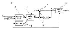
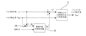
本実施形態3では、指令値と検出値の偏差に対して一般化周期外乱オブザーバを適用し、偏差に含まれる周期外乱を抑制する手法を説明する。図17は、トルク誤差に対して周期外乱抑制制御を実施する場合の制御構成図である。
[Embodiment 3]
In the third embodiment, a method for suppressing a periodic disturbance included in the deviation by applying a generalized periodic disturbance observer to the deviation between the command value and the detected value will be described. FIG. 17 is a control configuration diagram in the case where the periodic disturbance suppression control is performed on the torque error.
なお、このときの周期外乱抑制制御器8は、図14のトルク検出値τdetをトルク偏差Δτに置き換えて用いれば良い。また、周期外乱指令値のn次周波数成分ベクトルDn *は、トルク偏差をなくすことが目的であるから、ゼロに設定する。
Note that the periodic
したがって、図14の制御ブロックを等価変換すると、周期外乱抑制制御器8は図18のように構成できる。図18に示すように、図16の減算器16,17が省略され、操作量推定値のn次周波数成分ベクトルUn^と周期外乱補償値のn次周波数成分ベクトルTpDn *を低域通過フィルタGF(s)に通した値と、を加算する加算器19が設けられている。また、加算器19の出力が周期外乱補償値のn次周波数成分ベクトルTpDn *となる。
Therefore, if the control block of FIG. 14 is equivalently converted, the periodic
図18の周期外乱のn次周波数成分ベクトルTnは、(8)式のトルク検出値τdetにΔτを代入して求める。 N order frequency component vector T n cycle disturbance 18 is obtained by substituting Δτ to (8) of the torque detection value tau det.
以上示したように、本実施形態3によれば、実施形態1と同様の作用効果を奏する。また、実施形態2で説明したように、直流トルク成分Tdcに周期外乱が重畳された場合であっても、トルク偏差Δτを用いることで直流トルク成分Tdcが予め除去された状態で周期外乱オブザーバを動作させることが可能となる。 As described above, according to the third embodiment, the same operational effects as those of the first embodiment can be obtained. In addition, as described in the second embodiment, even when a periodic disturbance is superimposed on the DC torque component Tdc, the periodic disturbance observer can be used in a state where the DC torque component Tdc is removed in advance by using the torque deviation Δτ. It becomes possible to operate.
すなわち、実施形態2で構成したようなハイパスフィルタは不要でありながら、実施形態2と同等の効果が得られ、図18のように、より簡素化された制御構成で実現できる利点がある。 That is, the high pass filter as configured in the second embodiment is unnecessary, but the same effect as in the second embodiment can be obtained, and there is an advantage that can be realized with a more simplified control configuration as shown in FIG.
[実施形態4]
実施形態3の図18の構成において、一般化周期外乱オブザーバの周波数成分抽出に用いる低域通過フィルタGF(s)を(12)式に示す1次のローパスフィルタに設定した場合、図18は図19のように制御ブロック図に等価変換できる。
[Embodiment 4]
In the configuration of FIG. 18 of the third embodiment, when the low-pass filter G F (s) used for frequency component extraction of the generalized periodic disturbance observer is set to the first-order low-pass filter shown in the equation (12), FIG. As shown in FIG. 19, it can be equivalently converted into a control block diagram.
図19は、図18の周波数成分抽出器9を周波数成分変換器20に変更し、低域通過フィルタGF(s)を積分器13に変更している。すなわち、図18の周波数成分抽出器9の内部にある低域通過フィルタGF(s)を外に出す。そして、積分器13は、周波数成分抽出器9の内部にある低域通過フィルタGF(s)と後段の低域通過フィルタGF(s)と合成した結果で得られ、カットオフ周波数ωfと逆モデルをゲインとした単純な積分器13となる。このように図18は図19に等価変換できる。ただし、図19の周波数成分変換器20は、(8)式の代わりに以下の(13)式を用いる。
In FIG. 19, the
(13)式には低域通過フィルタGF(s)がないため、トルク偏差Δτに含まれる周期外乱の周波数成分を明示的に抽出することをせずに、直接、周期外乱補償値のn次周波数成分ベクトルTpDn *を生成することになる。 Since there is no low-pass filter G F (s) in the equation (13), the periodic disturbance compensation value n is directly extracted without explicitly extracting the frequency component of the periodic disturbance included in the torque deviation Δτ. The next frequency component vector T pDn * is generated.
以上より、本実施形態4によれば、実施形態1と同様の作用効果を奏する。また、低域通過フィルタGF(s)を1次に限定した場合、トルク偏差Δτに対する一般化周期外乱オブザーバは、ゲインと積分器という非常に簡単な構成で実現できるため、制御に係る演算量を低減できる。 As described above, according to the fourth embodiment, the same effects as those of the first embodiment can be obtained. When the low-pass filter G F (s) is limited to the first order, the generalized periodic disturbance observer for the torque deviation Δτ can be realized with a very simple configuration of a gain and an integrator. Can be reduced.
[実施形態5]
これまでの実施形態1〜4では、共振および非周期外乱抑制制御器7において、定常トルクを含む低周波数域のトルク制御も実施するコントローラを設計していた。つまり、高周波数域にある共振抑制も含めて、全周波数帯域でのコントローラとなるが、一般にμ設計等のロバスト制御で全周波数帯域をカバーする制御器を設計した場合、制御性能が保守的になったり、コントローラの次数が高くなる傾向がある。
[Embodiment 5]
In the first to fourth embodiments so far, in the resonance and non-periodic
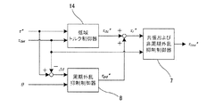
そこで、本実施形態5では、図20に示すように共振および非周期外乱抑制制御器7において、高周波数領域にある共振抑制と非周期外乱抑制に注力し、定常トルク制御を含む低域トルク制御器14により一般的なPI制御器で実現し、それらをマイナーループに含んだ周期外乱抑制制御器8を付加する手法を説明する。
Therefore, in the fifth embodiment, as shown in FIG. 20, the resonance and non-periodic
図21は、トルク制御の例における制御の基本構成図となる。なお、本実施形態5における周期外乱抑制制御器8は、実施形態3のトルク偏差に対する一般化周期外乱オブザーバの構成を基に説明するが、もちろん実施形態1やそのほかの構成を採っても良い。
FIG. 21 is a basic configuration diagram of control in an example of torque control. In addition, although the periodic
まず、低域トルク制御器14の機能について説明する。
First, the function of the low
2慣性共振系において、機械系の定常トルク(直流トルク)の特性はモータと負荷の慣性モーメントの比で決定づけられる。モータの慣性モーメントをJ1,負荷の慣性モーメントJ2とした場合、定常トルクτdet(dc)は(14)式で示される。なお、(dc)は直流成分を意味する。 In the two-inertia resonance system, the characteristic of the steady torque (DC torque) of the mechanical system is determined by the ratio of the moment of inertia of the motor and the load. When the inertia moment of the motor is J1 and the inertia moment J2 of the load, the steady torque τ det (dc) is expressed by equation (14). Note that (dc) means a DC component.
このように、簡易的に慣性比が分かれば、予めそのトルク誤差をある程度補正することも可能であるが、実際にはインバータのトルク誤差や慣性モーメントの設計値からの誤差,粘性摩擦損失等も含まれるため、トルクフィードバック制御によって定常トルクを制御する必要がある。 In this way, if the inertia ratio is simply known, it is possible to correct the torque error to some extent in advance. In practice, however, the torque error of the inverter, the error from the design value of the moment of inertia, viscous friction loss, etc. Therefore, it is necessary to control the steady torque by torque feedback control.
一方で、図6に示したように高周波数領域では2慣性系によるシステム共振点があるため、一般的なPID制御等の構成で全周波数帯域に亘るトルクフィードバック制御を実施した場合、制御が不安定となりやすく、周波数領域での共振抑制を実施することは難しい。 On the other hand, as shown in FIG. 6, since there is a system resonance point by a two-inertia system in the high frequency region, when torque feedback control over the entire frequency band is performed with a general configuration such as PID control, control is not possible. It tends to be stable, and it is difficult to suppress resonance in the frequency domain.
そこで、本実施形態5では、定常トルクを含む低周波数領域のトルク誤差をなくすためだけに寄与するPI制御器を構成する。一例として、図21に低域トルク制御器14の構成例を示す。
Therefore, in the fifth embodiment, a PI controller that contributes only to eliminate the torque error in the low frequency region including the steady torque is configured. As an example, FIG. 21 shows a configuration example of the low-
図21では、一例として比例先行型I−P制御器を基本とし、その出力に低域通過フィルタGF(s)を介して直流トルク成分指令値τdc *を出力する構成を用いている。低域通過フィルタGF(s)は、高域にあるシステム共振特性の影響を除去するためのフィルタであり、このフィルタの通過帯域、すなわち、低周波数領域においてPI制御器が機能する構造を持つ。これにより、高周波帯域でPI制御器が不安定とならないように設計している。低域通過フィルタGF(s)の設計は任意であるが、例えば二項係数標凖形の2次ローパスフィルタで共振周波数の0.1倍程度のカットオフ周波数に設計する。 In FIG. 21, as an example, a proportional leading IP controller is used as a basis, and a configuration in which a DC torque component command value τ dc * is output to the output via a low-pass filter G F (s) is used. The low-pass filter G F (s) is a filter for removing the influence of the system resonance characteristic in the high band, and has a structure in which the PI controller functions in the pass band of the filter, that is, in the low-frequency region. . As a result, the PI controller is designed not to become unstable in the high frequency band. The design of the low-pass filter G F (s) is arbitrary. For example, the low-pass filter G F (s) is designed to have a cutoff frequency that is about 0.1 times the resonance frequency by a binarized coefficient sign-shaped secondary low-pass filter.
低域通過フィルタGF(s)を用いることにより、本制御器が制御対象とするシステム特性は等価的に2次系ローパスフィルタ特性に近似されるため、本制御器の閉ループ特性は3次系となる。3次系の閉ループ特性を例えば二項係数標準形の参照モデルにマッチングさせることにより、(15)式のようにKp,Kiが求められる。 By using the low-pass filter G F (s), the system characteristics controlled by this controller are equivalently approximated to the second-order low-pass filter characteristics. Therefore, the closed-loop characteristic of this controller is the third-order system. It becomes. By matching the closed-loop characteristic of the cubic system with, for example, a binomial coefficient standard form reference model, Kp and Ki are obtained as in equation (15).
ここで、ωcは、所望する任意の閉ループ応答周波数である。ωlpfは2次ローパスフィルタのカットオフ周波数、kは2次ローパスフィルタの係数(二項係数標準型は2,バターワース型は1.4など、フィルタ形式に従って指定する係数),a2およびa1は3次系参照モデルの係数(二項係数標準形ならばa1=a2=3,バターワース型ならばa1=a2=2など)である。 Where ωc is any desired closed loop response frequency. ω lpf is the cutoff frequency of the second-order low-pass filter, k is the coefficient of the second-order low-pass filter (binary coefficient standard type is 2, Butterworth type is 1.4, etc.), a2 and a1 are 3 The coefficient of the next system reference model (a1 = a2 = 3 for the binomial coefficient standard form, a1 = a2 = 2 for the Butterworth type, etc.).
この低域トルク制御器14によって、定常トルクを含む低周波領域のトルク誤差をなくし、安定的に制御することができる。ただし、低域トルク制御器14のみでは高周波数領域の共振を抑制することはできないので、前述の共振および非周期外乱抑制制御器7を用いて抑制する。
This low-
低周波数領域のトルク追従制御は低域トルク制御器14で実現するため、高周波数領域の共振および非周期外乱抑制制御器7では、低周波数領域におけるコントローラゲインを低くした設計を行う。例えば、μ設計制御器を用いる場合、一般化プラントを図22のように構成し、μ設計制御器入力(補正指令値)rからμ設計制御器出力(操作量)uのゲインに対して、重み関数We(s)を介してμ設計制御器ゲインの評価出力を設定する。We(s)では、前述の低域トルク制御器14との制御干渉を防ぐために、低域に対する重み付けをする。図22の符号は以下の通りである。
J1:モータの慣性モーメント,J2:負荷の慣性モーメント,K12:軸ねじれ剛性,s:ラプラス演算子,Δτ:定常トルク誤差,Gtm(s):トルクメータ等の検出応答伝達関数,Ginv(s):インバータ応答伝達関数,d1:外乱(周期外乱を含む),d2およびr:μ設計制御器入力,d3:トルク検出ノイズ
z:定常トルク誤差の評価出力,w:定常トルク誤差による外乱入力,u:μ設計制御器出力(操作量),y:観測出力(検出値),e1:トルク検出値の評価出力,e2:インバータトルク指令の評価出力,e3:μ設計制御器ゲインの評価出力,Wn(s):外乱d1に対する重み関数,Wu(s):インバータトルク指令Uに対する重み関数,We(s):μ設計制御器ゲインに対する重み関数。
Since the low-frequency region torque follow-up control is realized by the low-frequency
J1: Motor inertia moment, J2: Load inertia moment, K12: Shaft torsional rigidity, s: Laplace operator, Δτ: Steady torque error, G tm (s): Detection response transfer function of torque meter, G inv ( s): inverter response transfer function, d1: disturbance (including periodic disturbance), d2 and r: μ design controller input, d3: torque detection noise z: evaluation output of steady torque error, w: disturbance input due to steady torque error , U: μ design controller output (operation amount), y: observation output (detection value), e1: torque detection value evaluation output, e2: inverter torque command evaluation output, e3: μ design controller gain evaluation output , W n (s): Weight function for disturbance d1, W u (s): Weight function for inverter torque command U, W e (s): Weight function for μ design controller gain.
実施形態1と同様に、伝達特性Cref(s)と伝達特性Ctm(s)をもつμ設計制御器を設計し、図11に示す構成で、図20の共振および非周期外乱抑制制御器7の部分に実装する。さらに、低域トルク制御器14が出力する直流トルク成分指令値τdc *と周期外乱抑制制御器8が出力する周期外乱抑制制御器出力τpd *を加算して、補正トルク指令値τr *を生成して共振および非周期外乱抑制制御器7に入力する。
Similarly to the first embodiment, a μ design controller having a transfer characteristic Cref (s) and a transfer characteristic Ctm (s) is designed, and the configuration of the resonance and non-periodic
上述で得られた共振および非周期外乱抑制制御器7および低域トルク制御器14を実装し、周期外乱抑制制御器8のみは動作させない状態において、周期外乱抑制制御器出力τpd *からトルク検出値τdetまでの閉ループ周波数伝達特性を図23に示す。この周波数伝達特性を利用し、一般化周期外乱オブザーバの逆モデルQn^を設定する。このようにして、周期外乱抑制制御器8から見たマイナーループのモデルを設定し、周期外乱オブザーバを安定に動作させるとともに、共振・非周期外乱・周期外乱を同時に抑制する。
In the state where the resonance and non-periodic
本実施形態5によるトルク制御の結果を図24に示す。共振・非周期外乱・周期外乱を良好に抑制できていることが確認できる。 The results of torque control according to the fifth embodiment are shown in FIG. It can be confirmed that the resonance / non-periodic disturbance / periodic disturbance can be satisfactorily suppressed.
本実施形態5によれば、実施形態1と同様の作用効果を奏する。また、以下の効果が期待できる。 According to the fifth embodiment, the same operational effects as those of the first embodiment are obtained. In addition, the following effects can be expected.
低域と高域の制御器を分離することで、低域ではPID制御等の従来的手法で制御調整が容易となる。 By separating the low-frequency and high-frequency controllers, control adjustment is facilitated by conventional methods such as PID control in the low frequency range.
また、高域の共振抑制制御を実施するμ設計等のロバスト制御器では、低域のトルク追従性能を考慮する必要がなくなるため、共振抑圧性能や即応性向上を目指した設計が容易となる。 In addition, in a robust controller such as a μ design that performs high-frequency resonance suppression control, it is not necessary to consider low-frequency torque tracking performance, so that it is easy to design for improved resonance suppression performance and quick response.
[実施形態6]
実施形態1〜5に関わる「一般化周期外乱オブザーバ」は、特定周波数成分のみに寄与する周期外乱抑制制御器ではあるが、本実施形態6では、抑制したい次数を別個指定し、それらの一般化周期外乱オブザーバを並列化し、補償信号合成部において、並列化した周期外乱補償値を合算することで、複数の周波数成分の周期外乱を同時に抑制することができる。
[Embodiment 6]
Although the “generalized periodic disturbance observer” related to the first to fifth embodiments is a periodic disturbance suppression controller that contributes only to a specific frequency component, in the sixth embodiment, the orders to be suppressed are separately specified and generalized. By parallelizing periodic disturbance observers and adding together the parallel periodic disturbance compensation values in the compensation signal synthesis unit, periodic disturbances of a plurality of frequency components can be suppressed simultaneously.
以上、本発明において、記載された具体例に対してのみ詳細に説明したが、本発明の技術思想の範囲で多彩な変形および修正が可能であることは、当業者にとって明白なことであり、このような変形および修正が特許請求の範囲に属することは当然のことである。 Although the present invention has been described in detail only for the specific examples described above, it is obvious to those skilled in the art that various changes and modifications are possible within the scope of the technical idea of the present invention. Such variations and modifications are naturally within the scope of the claims.
1…フィードバック制御器
2…制御対象システム
3…共振・外乱抑制制御器
4…周期外乱抑制制御器
5…トルク制御器
6…トルクメータ
7…共振および非周期外乱抑制制御器
8…周期外乱抑制制御器
9…周波数成分抽出器
10…速度変換器
11…補償信号合成部
12…高域通過フィルタ
13…積分器
14…低域トルク制御器
15…逆モデル乗算器
20…周波数成分変換器
DESCRIPTION OF
Claims (8)
前記フィードバック制御器は、
前記検出値と前記位相情報とに基づいて、周期外乱補償信号を出力する周期外乱抑制制御器と、
前記指令値と前記周期外乱補償信号とを加算した補正指令値と、前記検出値と、に基づいて、前記操作量を算出する共振・外乱抑制制御器と、を有し、
前記周期外乱抑制制御器は一般化周期外乱オブザーバを用いることを特徴とする制御システム。 A control system including a feedback controller that determines an operation amount of a control target system based on a command value, a detection value of the control target system, and phase information of the control target system,
The feedback controller is
A periodic disturbance suppression controller that outputs a periodic disturbance compensation signal based on the detected value and the phase information;
A resonance / disturbance suppression controller that calculates the manipulated variable based on a correction command value obtained by adding the command value and the periodic disturbance compensation signal, and the detected value,
The periodic disturbance suppression controller uses a generalized periodic disturbance observer.
前記指令値がμ設計制御器の前記指令値から前記操作量までの伝達特性を介した出力と、前記検出値がμ設計制御器の前記検出値から前記操作量までの伝達特性を介した出力と、を加算して、前記操作量を出力するμ設計制御器を有し、
前記周期外乱抑制制御器は、
前記位相情報に抑制対象次数nを乗じたn次回転位相を用いて、前記検出値から周波数成分を抽出し、dnqn回転座標に変換した周期外乱のn次周波数成分ベクトルを出力する周波数成分抽出器と、
前記n次回転位相を微分してn次回転周波数を算出する速度変換器と、
前記周期外乱のn次周波数成分ベクトルに、前記n次回転周波数に同期した単一の周波数ベクトルが適用された逆モデルを乗じて、操作量推定値のn次周波数成分ベクトルを求める逆モデル乗算部と、
前記操作量推定値のn次周波数成分ベクトルから、周期外乱補償値のn次周波数成分ベクトルが低域通過フィルタを介した値を減算して周期外乱推定値のn次周波数成分ベクトルを出力する第1減算器と、
周期外乱指令値のn次周波数成分ベクトルから、前記周期外乱推定値のn次周波数成分ベクトルを減算して、周期外乱補償値のn次周波数成分ベクトルを出力する第2減算器と、
前記周期外乱補償値のn次周波数成分ベクトルを、前記n次回転位相に基づいて、周期外乱に同期したdnqn回転座標系から元の時間波形に復元し、前記周期外乱補償信号を出力する補償信号合成部と、
を備えたことを特徴とする請求項1記載の制御システム。 The resonance / disturbance suppression controller is
The command value is output via the transfer characteristic from the command value of the μ design controller to the manipulated variable, and the detection value is output via the transfer characteristic of the detected value of the μ design controller to the manipulated variable. And a μ design controller that outputs the manipulated variable,
The periodic disturbance suppression controller is
A frequency at which a frequency component is extracted from the detected value using an n-th rotation phase obtained by multiplying the phase information by the suppression target order n, and an n-order frequency component vector of a periodic disturbance converted into a dn q n rotation coordinate is output. A component extractor;
A speed converter for differentiating the n-th rotational phase to calculate an n-th rotational frequency;
An inverse model multiplying unit that multiplies the nth order frequency component vector of the periodic disturbance by an inverse model in which a single frequency vector synchronized with the nth order rotation frequency is applied to obtain an nth order frequency component vector of the manipulated variable estimated value. When,
The n-th order frequency component vector of the periodic disturbance estimated value is output by subtracting the value of the n-th order frequency component vector of the periodic disturbance compensation value from the n-th order frequency component vector of the manipulated variable estimated value through a low-pass filter. 1 subtractor,
A second subtractor for subtracting the n-th order frequency component vector of the estimated periodic disturbance value from the n-th order frequency component vector of the periodic disturbance command value and outputting an n-order frequency component vector of the periodic disturbance compensation value;
The n-th frequency component vector of the periodic disturbance compensation values, based on said n-order rotational phase, and recovered from d n q n rotational coordinate system synchronized with the periodic disturbance to the original time waveform, outputs the periodic disturbance compensation signal A compensation signal synthesizing unit,
The control system according to claim 1, further comprising:
前記指令値がμ設計制御器の前記指令値から前記操作量までの伝達特性を介した出力と、前記検出値が設計制御器の前記検出値から前記操作量までの伝達特性を介した出力と、を加算して、前記操作量を出力するμ設計制御器を有し、
前記周期外乱抑制制御器は、
前記位相情報に抑制対象次数nを乗じたn次回転位相を用いて、前記指令値から前記検出値を減算した偏差から周波数成分を抽出し、dnqn回転座標に変換した周期外乱のn次周波数成分ベクトルを出力する周波数成分抽出器と、
前記n次回転位相を微分してn次回転周波数を算出する速度変換器と、
周期外乱のn次周波数成分ベクトルに、前記n次回転周波数に同期した単一の周波数ベクトルが適用された逆モデルを乗じて、操作量推定値のn次周波数成分ベクトルを求める逆モデル乗算部と、
前記操作量推定値のn次周波数成分ベクトルと、周期外乱補償値のn次周波数成分ベクトルが低域通過フィルタを介した値と、を加算して周期外乱補償値のn次周波数成分ベクトルを出力する加算器と、
前記周期外乱補償値のn次周波数成分ベクトルを、前記n次回転位相に基づいて、周期外乱に同期したdnqn回転座標系から元の時間波形に復元し、前記周期外乱補償信号を出力する補償信号合成部と、
を備えたことを特徴とする請求項1記載の制御システム。 The resonance / disturbance suppression controller is
The command value is output via the transfer characteristic from the command value of the μ design controller to the manipulated variable, and the detected value is output via the transfer characteristic of the design controller from the detected value to the manipulated variable. , And a μ design controller that outputs the manipulated variable,
The periodic disturbance suppression controller is
Using the n-th rotational phase obtained by multiplying the phase information by the suppression target order n, the frequency component is extracted from the deviation obtained by subtracting the detected value from the command value, and the period disturbance n converted to dn q n rotational coordinates A frequency component extractor that outputs a second frequency component vector;
A speed converter for differentiating the n-th rotational phase to calculate an n-th rotational frequency;
An inverse model multiplying unit that multiplies the nth order frequency component vector of the periodic disturbance by an inverse model in which a single frequency vector synchronized with the nth order rotation frequency is applied to obtain an nth order frequency component vector of the manipulated variable estimation value; ,
The n-order frequency component vector of the manipulated variable estimate value and the n-order frequency component vector of the periodic disturbance compensation value are added through the low-pass filter to output the n-order frequency component vector of the periodic disturbance compensation value. An adder to
The n-th frequency component vector of the periodic disturbance compensation values, based on said n-order rotational phase, and recovered from d n q n rotational coordinate system synchronized with the periodic disturbance to the original time waveform, outputs the periodic disturbance compensation signal A compensation signal synthesizing unit,
The control system according to claim 1, further comprising:
前記指令値がμ設計制御器の前記指令値から前記操作量までの伝達特性を介した出力と、前記検出値がμ設計制御器の前記検出値から前記操作量までの伝達特性を介した出力と、を加算して、前記操作量を出力するμ設計制御器を有し、
前記周期外乱抑制制御器は、
前記位相情報に抑制対象次数nを乗じたn次回転位相を用いて、前記指令値から前記検出値を減算した偏差を、dnqn回転座標に変換した周期外乱のn次周波数成分ベクトルを出力する周波数成分変換器と、
前記n次回転位相を微分してn次回転周波数を算出する速度変換器と、
前記周期外乱のn次周波数成分ベクトルに、前記n次回転周波数に同期した単一の周波数ベクトルが適用された逆モデルを乗じて、操作量推定値のn次周波数成分ベクトルを求める逆モデル乗算部と、
前記操作量推定値のn次周波数成分ベクトルを積分し、周期外乱補償値のn次周波数成分ベクトルを出力する積分器と、
前記周期外乱補償値のn次周波数成分ベクトルを、前記n次回転位相に基づいて、周期外乱に同期したdnqn回転座標系から元の時間波形に復元し、前記周期外乱補償信号を出力する補償信号合成部と、
を備えたことを特徴とする請求項1記載の制御システム。 The resonance / disturbance suppression controller is
The command value is output via the transfer characteristic from the command value of the μ design controller to the manipulated variable, and the detection value is output via the transfer characteristic of the detected value of the μ design controller to the manipulated variable. And a μ design controller that outputs the manipulated variable,
The periodic disturbance suppression controller is
An n-order frequency component vector of a periodic disturbance obtained by converting a deviation obtained by subtracting the detection value from the command value into a d n q n rotation coordinate using an n-order rotation phase obtained by multiplying the phase information by the suppression target order n. An output frequency component converter;
A speed converter for differentiating the n-th rotational phase to calculate an n-th rotational frequency;
An inverse model multiplying unit that multiplies the nth order frequency component vector of the periodic disturbance by an inverse model in which a single frequency vector synchronized with the nth order rotation frequency is applied to obtain an nth order frequency component vector of the manipulated variable estimated value. When,
An integrator that integrates the n-order frequency component vector of the manipulated variable estimation value and outputs the n-order frequency component vector of the periodic disturbance compensation value;
The n-th frequency component vector of the periodic disturbance compensation values, based on said n-order rotational phase, and recovered from d n q n rotational coordinate system synchronized with the periodic disturbance to the original time waveform, outputs the periodic disturbance compensation signal A compensation signal synthesizing unit,
The control system according to claim 1, further comprising:
前記直流トルク成分指令値と前記周期外乱補償信号を加算した値を前記補正指令値とし、
前記低域トルク制御器は、
PI制御器と、低域通過フィルタと、を備えたことを特徴とする請求項1〜5のうち何れか1項に記載の制御システム。 Based on the command value and the detected value, a low-frequency torque controller that outputs a DC torque component command value,
A value obtained by adding the DC torque component command value and the periodic disturbance compensation signal is the correction command value,
The low-frequency torque controller is
The control system according to claim 1, further comprising a PI controller and a low-pass filter.
前記トルク制御器は、
前記トルク検出値と前記位相情報とに基づいて、周期外乱補償信号を出力する周期外乱抑制制御器と、
前記トルク指令値と前記周期外乱補償信号とを加算した補正トルク指令値と、前記トルク検出値と、に基づいて、前記インバータトルク指令値を算出する共振・外乱抑制制御器と、を有し、
前記周期外乱抑制制御器は一般化周期外乱オブザーバを用いることを特徴とする制御システム。 A control system including a torque controller that calculates an inverter torque command value of the inverter based on a torque command value, a torque detection value, and phase information of a motor driven by the inverter,
The torque controller is
A periodic disturbance suppression controller that outputs a periodic disturbance compensation signal based on the torque detection value and the phase information;
A resonance / disturbance suppression controller that calculates the inverter torque command value based on the corrected torque command value obtained by adding the torque command value and the periodic disturbance compensation signal and the torque detection value;
The periodic disturbance suppression controller uses a generalized periodic disturbance observer.
Priority Applications (4)
| Application Number | Priority Date | Filing Date | Title |
|---|---|---|---|
| JP2016126129A JP6197923B1 (en) | 2016-06-27 | 2016-06-27 | Control system |
| US16/313,558 US10558176B2 (en) | 2016-06-27 | 2017-03-15 | Feedback control system with periodic disturbance suppression and resonance/disturbance suppression using μ-synthesis |
| PCT/JP2017/010427 WO2018003200A1 (en) | 2016-06-27 | 2017-03-15 | Control system |
| KR1020197002650A KR102002144B1 (en) | 2016-06-27 | 2017-03-15 | Control system |
Applications Claiming Priority (1)
| Application Number | Priority Date | Filing Date | Title |
|---|---|---|---|
| JP2016126129A JP6197923B1 (en) | 2016-06-27 | 2016-06-27 | Control system |
Publications (2)
| Publication Number | Publication Date |
|---|---|
| JP6197923B1 JP6197923B1 (en) | 2017-09-20 |
| JP2018005259A true JP2018005259A (en) | 2018-01-11 |
Family
ID=59895629
Family Applications (1)
| Application Number | Title | Priority Date | Filing Date |
|---|---|---|---|
| JP2016126129A Active JP6197923B1 (en) | 2016-06-27 | 2016-06-27 | Control system |
Country Status (4)
| Country | Link |
|---|---|
| US (1) | US10558176B2 (en) |
| JP (1) | JP6197923B1 (en) |
| KR (1) | KR102002144B1 (en) |
| WO (1) | WO2018003200A1 (en) |
Cited By (1)
| Publication number | Priority date | Publication date | Assignee | Title |
|---|---|---|---|---|
| JP2019193408A (en) * | 2018-04-24 | 2019-10-31 | 富士電機株式会社 | Vibration suppression device and linear motor control device |
Families Citing this family (3)
| Publication number | Priority date | Publication date | Assignee | Title |
|---|---|---|---|---|
| CN110323974B (en) * | 2019-08-07 | 2021-05-07 | 哈尔滨工业大学 | Active disturbance rejection control method based on proportional resonant controller optimization |
| CN113341714B (en) * | 2021-06-02 | 2022-05-27 | 南京工业大学 | Method for counteracting same frequency interference of magnetic suspension bearing rotor control system |
| CN113625555A (en) * | 2021-06-30 | 2021-11-09 | 佛山科学技术学院 | Adaptive inverse control AGV rotation speed control method based on recursive subspace identification |
Family Cites Families (9)
| Publication number | Priority date | Publication date | Assignee | Title |
|---|---|---|---|---|
| SE7412459L (en) | 1973-10-18 | 1975-04-21 | Lee Hunter | |
| JP3772721B2 (en) | 2001-10-11 | 2006-05-10 | 株式会社明電舎 | Engine bench system and method for measuring engine characteristics |
| JP3775284B2 (en) | 2001-11-08 | 2006-05-17 | 株式会社明電舎 | Engine bench system and method for measuring engine characteristics |
| WO2010024195A1 (en) * | 2008-08-26 | 2010-03-04 | 株式会社明電舎 | Electric motor disturbance suppression device and disturbance suppression method |
| JP5446988B2 (en) * | 2010-02-25 | 2014-03-19 | 株式会社明電舎 | Torque ripple suppression control device and control method for rotating electrical machine |
| CN103492962B (en) * | 2011-04-15 | 2016-11-02 | 株式会社明电舍 | Rejection of Cyclic Disturbances equipment and Rejection of Cyclic Disturbances method |
| JP5532115B1 (en) * | 2012-12-07 | 2014-06-25 | 株式会社明電舎 | Periodic disturbance automatic suppression device |
| US9729094B2 (en) * | 2013-06-10 | 2017-08-08 | Meidensha Corporation | Automatic suppression device for cyclic disturbance |
| KR101716250B1 (en) * | 2014-03-11 | 2017-03-15 | 메이덴샤 코포레이션 | Drivetrain testing system |
-
2016
- 2016-06-27 JP JP2016126129A patent/JP6197923B1/en active Active
-
2017
- 2017-03-15 KR KR1020197002650A patent/KR102002144B1/en active IP Right Grant
- 2017-03-15 US US16/313,558 patent/US10558176B2/en active Active
- 2017-03-15 WO PCT/JP2017/010427 patent/WO2018003200A1/en active Application Filing
Cited By (2)
| Publication number | Priority date | Publication date | Assignee | Title |
|---|---|---|---|---|
| JP2019193408A (en) * | 2018-04-24 | 2019-10-31 | 富士電機株式会社 | Vibration suppression device and linear motor control device |
| JP7214976B2 (en) | 2018-04-24 | 2023-01-31 | 富士電機株式会社 | Vibration suppression device and linear motor control device |
Also Published As
| Publication number | Publication date |
|---|---|
| JP6197923B1 (en) | 2017-09-20 |
| US20190227500A1 (en) | 2019-07-25 |
| KR20190018014A (en) | 2019-02-20 |
| WO2018003200A1 (en) | 2018-01-04 |
| KR102002144B1 (en) | 2019-10-01 |
| US10558176B2 (en) | 2020-02-11 |
Similar Documents
| Publication | Publication Date | Title |
|---|---|---|
| JP6197923B1 (en) | Control system | |
| KR101328494B1 (en) | Torque ripple suppression control apparatus and torque ripple suppression control method for rotating electrical machine | |
| JP5088414B2 (en) | Disturbance suppression device and disturbance suppression method for electric motor | |
| JP5273575B2 (en) | Electric motor control device | |
| JP6172349B1 (en) | Motor drive system | |
| US9490734B2 (en) | Motor control device and method of controlling the same | |
| JP3892823B2 (en) | Motor speed control device | |
| JP5652678B2 (en) | Electric motor control device | |
| JP5644409B2 (en) | Electric motor position control device | |
| JP2011257205A (en) | Axial torque controller for dynamometer system | |
| JP2014023370A (en) | Disturbance observer for two-inertia system and speed control device employing the same | |
| JP2018156557A (en) | Method for designing delay compensator filter, and feedback control method and motor controller using same | |
| JP5017984B2 (en) | Servo control device and speed tracking control method thereof | |
| JP4788656B2 (en) | Power test system | |
| JP5998663B2 (en) | AC motor drive control device | |
| JP6341770B2 (en) | Two-phase signal phase detection device and two-phase signal phase detection method | |
| JP5981277B2 (en) | Position detection device | |
| Al-Badrani et al. | Enhanced Speed Control of a Drive With Rejection of Periodical Disturbances | |
| JP2005168212A (en) | Motor control device | |
| Naifar et al. | Observer Design and Sensorless Control in Electrical Machines: A Brief Overview | |
| Luckert et al. | Novel Extended Robust Disturbance Observer for Improved Cogging Force Compensation in Permanent Magnet Linear Motors | |
| JP2010161854A (en) | Motor controller | |
| Kani et al. | Characteristic Analysis of DFT based Specified Component Reduction Controller | |
| JP2008278626A (en) | Servo controller and its control method | |
| JP2019012009A (en) | Position data filter |
Legal Events
| Date | Code | Title | Description |
|---|---|---|---|
| A521 | Written amendment |
Free format text: JAPANESE INTERMEDIATE CODE: A523 Effective date: 20170626 |
|
| TRDD | Decision of grant or rejection written | ||
| A01 | Written decision to grant a patent or to grant a registration (utility model) |
Free format text: JAPANESE INTERMEDIATE CODE: A01 Effective date: 20170725 |
|
| A61 | First payment of annual fees (during grant procedure) |
Free format text: JAPANESE INTERMEDIATE CODE: A61 Effective date: 20170807 |
|
| R150 | Certificate of patent or registration of utility model |
Ref document number: 6197923 Country of ref document: JP Free format text: JAPANESE INTERMEDIATE CODE: R150 |