JP2018005182A - Image forming apparatus - Google Patents
Image forming apparatus Download PDFInfo
- Publication number
- JP2018005182A JP2018005182A JP2016136078A JP2016136078A JP2018005182A JP 2018005182 A JP2018005182 A JP 2018005182A JP 2016136078 A JP2016136078 A JP 2016136078A JP 2016136078 A JP2016136078 A JP 2016136078A JP 2018005182 A JP2018005182 A JP 2018005182A
- Authority
- JP
- Japan
- Prior art keywords
- image forming
- forming apparatus
- exterior member
- unit
- sheet
- Prior art date
- Legal status (The legal status is an assumption and is not a legal conclusion. Google has not performed a legal analysis and makes no representation as to the accuracy of the status listed.)
- Pending
Links
Images


Classifications
-
- B—PERFORMING OPERATIONS; TRANSPORTING
- B65—CONVEYING; PACKING; STORING; HANDLING THIN OR FILAMENTARY MATERIAL
- B65H—HANDLING THIN OR FILAMENTARY MATERIAL, e.g. SHEETS, WEBS, CABLES
- B65H43/00—Use of control, checking, or safety devices, e.g. automatic devices comprising an element for sensing a variable
- B65H43/04—Use of control, checking, or safety devices, e.g. automatic devices comprising an element for sensing a variable detecting, or responding to, presence of faulty articles
-
- B—PERFORMING OPERATIONS; TRANSPORTING
- B65—CONVEYING; PACKING; STORING; HANDLING THIN OR FILAMENTARY MATERIAL
- B65H—HANDLING THIN OR FILAMENTARY MATERIAL, e.g. SHEETS, WEBS, CABLES
- B65H7/00—Controlling article feeding, separating, pile-advancing, or associated apparatus, to take account of incorrect feeding, absence of articles, or presence of faulty articles
- B65H7/02—Controlling article feeding, separating, pile-advancing, or associated apparatus, to take account of incorrect feeding, absence of articles, or presence of faulty articles by feelers or detectors
- B65H7/06—Controlling article feeding, separating, pile-advancing, or associated apparatus, to take account of incorrect feeding, absence of articles, or presence of faulty articles by feelers or detectors responsive to presence of faulty articles or incorrect separation or feed
-
- G—PHYSICS
- G03—PHOTOGRAPHY; CINEMATOGRAPHY; ANALOGOUS TECHNIQUES USING WAVES OTHER THAN OPTICAL WAVES; ELECTROGRAPHY; HOLOGRAPHY
- G03G—ELECTROGRAPHY; ELECTROPHOTOGRAPHY; MAGNETOGRAPHY
- G03G15/00—Apparatus for electrographic processes using a charge pattern
- G03G15/50—Machine control of apparatus for electrographic processes using a charge pattern, e.g. regulating differents parts of the machine, multimode copiers, microprocessor control
- G03G15/5016—User-machine interface; Display panels; Control console
-
- B—PERFORMING OPERATIONS; TRANSPORTING
- B65—CONVEYING; PACKING; STORING; HANDLING THIN OR FILAMENTARY MATERIAL
- B65H—HANDLING THIN OR FILAMENTARY MATERIAL, e.g. SHEETS, WEBS, CABLES
- B65H2402/00—Constructional details of the handling apparatus
- B65H2402/40—Details of frames, housings or mountings of the whole handling apparatus
- B65H2402/45—Doors
-
- B—PERFORMING OPERATIONS; TRANSPORTING
- B65—CONVEYING; PACKING; STORING; HANDLING THIN OR FILAMENTARY MATERIAL
- B65H—HANDLING THIN OR FILAMENTARY MATERIAL, e.g. SHEETS, WEBS, CABLES
- B65H2511/00—Dimensions; Position; Numbers; Identification; Occurrences
- B65H2511/40—Identification
- B65H2511/417—Identification of state of the machine
-
- B—PERFORMING OPERATIONS; TRANSPORTING
- B65—CONVEYING; PACKING; STORING; HANDLING THIN OR FILAMENTARY MATERIAL
- B65H—HANDLING THIN OR FILAMENTARY MATERIAL, e.g. SHEETS, WEBS, CABLES
- B65H2511/00—Dimensions; Position; Numbers; Identification; Occurrences
- B65H2511/50—Occurence
- B65H2511/52—Defective operating conditions
- B65H2511/528—Jam
-
- B—PERFORMING OPERATIONS; TRANSPORTING
- B65—CONVEYING; PACKING; STORING; HANDLING THIN OR FILAMENTARY MATERIAL
- B65H—HANDLING THIN OR FILAMENTARY MATERIAL, e.g. SHEETS, WEBS, CABLES
- B65H2551/00—Means for control to be used by operator; User interfaces
- B65H2551/20—Display means; Information output means
- B65H2551/23—Analog displays
-
- B—PERFORMING OPERATIONS; TRANSPORTING
- B65—CONVEYING; PACKING; STORING; HANDLING THIN OR FILAMENTARY MATERIAL
- B65H—HANDLING THIN OR FILAMENTARY MATERIAL, e.g. SHEETS, WEBS, CABLES
- B65H2551/00—Means for control to be used by operator; User interfaces
- B65H2551/20—Display means; Information output means
- B65H2551/29—Means displaying permanently a particular information, e.g. mark, ruler
-
- B—PERFORMING OPERATIONS; TRANSPORTING
- B65—CONVEYING; PACKING; STORING; HANDLING THIN OR FILAMENTARY MATERIAL
- B65H—HANDLING THIN OR FILAMENTARY MATERIAL, e.g. SHEETS, WEBS, CABLES
- B65H2557/00—Means for control not provided for in groups B65H2551/00 - B65H2555/00
- B65H2557/60—Details of processes or procedures
- B65H2557/65—Details of processes or procedures for diagnosing
-
- B—PERFORMING OPERATIONS; TRANSPORTING
- B65—CONVEYING; PACKING; STORING; HANDLING THIN OR FILAMENTARY MATERIAL
- B65H—HANDLING THIN OR FILAMENTARY MATERIAL, e.g. SHEETS, WEBS, CABLES
- B65H2601/00—Problem to be solved or advantage achieved
- B65H2601/10—Ensuring correct operation
- B65H2601/11—Clearing faulty handling, e.g. jams
-
- G—PHYSICS
- G03—PHOTOGRAPHY; CINEMATOGRAPHY; ANALOGOUS TECHNIQUES USING WAVES OTHER THAN OPTICAL WAVES; ELECTROGRAPHY; HOLOGRAPHY
- G03G—ELECTROGRAPHY; ELECTROPHOTOGRAPHY; MAGNETOGRAPHY
- G03G21/00—Arrangements not provided for by groups G03G13/00 - G03G19/00, e.g. cleaning, elimination of residual charge
- G03G21/16—Mechanical means for facilitating the maintenance of the apparatus, e.g. modular arrangements
- G03G21/1604—Arrangement or disposition of the entire apparatus
- G03G21/1623—Means to access the interior of the apparatus
- G03G21/1633—Means to access the interior of the apparatus using doors or covers
-
- G—PHYSICS
- G03—PHOTOGRAPHY; CINEMATOGRAPHY; ANALOGOUS TECHNIQUES USING WAVES OTHER THAN OPTICAL WAVES; ELECTROGRAPHY; HOLOGRAPHY
- G03G—ELECTROGRAPHY; ELECTROPHOTOGRAPHY; MAGNETOGRAPHY
- G03G21/00—Arrangements not provided for by groups G03G13/00 - G03G19/00, e.g. cleaning, elimination of residual charge
- G03G21/16—Mechanical means for facilitating the maintenance of the apparatus, e.g. modular arrangements
- G03G21/1604—Arrangement or disposition of the entire apparatus
- G03G21/1623—Means to access the interior of the apparatus
- G03G21/1638—Means to access the interior of the apparatus directed to paper handling or jam treatment
-
- G—PHYSICS
- G03—PHOTOGRAPHY; CINEMATOGRAPHY; ANALOGOUS TECHNIQUES USING WAVES OTHER THAN OPTICAL WAVES; ELECTROGRAPHY; HOLOGRAPHY
- G03G—ELECTROGRAPHY; ELECTROPHOTOGRAPHY; MAGNETOGRAPHY
- G03G2221/00—Processes not provided for by group G03G2215/00, e.g. cleaning or residual charge elimination
- G03G2221/16—Mechanical means for facilitating the maintenance of the apparatus, e.g. modular arrangements and complete machine concepts
- G03G2221/1651—Mechanical means for facilitating the maintenance of the apparatus, e.g. modular arrangements and complete machine concepts for connecting the different parts
- G03G2221/1654—Locks and means for positioning or alignment
Abstract
Description
本発明は、複写機、プリンタ、ファクシミリ、又は、それらの複合機等の画像形成装置に関するものである。 The present invention relates to an image forming apparatus such as a copying machine, a printer, a facsimile, or a complex machine thereof.
従来から一般的に知られている画像形成装置では、カセットから給送された記録紙などのシートに転写部においてトナー像を転写し、定着部においてトナー像を定着し、その後、シートを装置外に排出する動作を行う。 In a conventionally known image forming apparatus, a toner image is transferred to a sheet of recording paper or the like fed from a cassette at a transfer unit, and the toner image is fixed at a fixing unit. The operation to discharge is performed.
上述した画像形成装置ではシートの搬送中に、シートの重送や搬送不良などで装置内にシートが滞留してしまい(以下ジャムという)、正常に装置外に排出されずに装置内にシートが残ってしまうことがある。その場合に、ユーザに装置の状況を知らせ、どの箇所にアクセスすればいいのかを知らせる手段として、扉や搬送ガイドにLED発光部を備えたものがある(特許文献1)。 In the image forming apparatus described above, the sheet stays in the apparatus during sheet conveyance due to double feeding or conveyance failure (hereinafter referred to as jam), and the sheet is not discharged out of the apparatus normally and is not discharged into the apparatus. It may remain. In that case, as a means for notifying the user of the status of the apparatus and which part should be accessed, there is a door or a conveyance guide provided with an LED light emitting unit (Patent Document 1).
しかしながら、従来の構成では、ユーザに対するLED発光部の視認性を上げるために、LED発光部が外装部材から突出した形状になっている。一般に扉などの外装部材は、ブランドロゴなどが配置され、意匠性、デザイン性が装置内部の部品に比べて高い。しかし、従来の構成では、LEDを点灯していない時にLED発光部が外装部材から突出しているので、デザイン性の観点等で満足できるものではなかった。またLED発光部は導光体となる材料で成形されており、高い難燃性等が求められる外装部材とは一般的に材料が異なるので、組立費や部品代などの製造上のコストが発生するという問題があった。 However, in the conventional configuration, in order to increase the visibility of the LED light emitting part to the user, the LED light emitting part has a shape protruding from the exterior member. In general, exterior members such as doors are provided with a brand logo and the like, and the design and design are higher than the parts inside the device. However, in the conventional configuration, the LED light-emitting portion protrudes from the exterior member when the LED is not lit, so that it is not satisfactory from the viewpoint of design. In addition, the LED light-emitting part is molded from the material used as the light guide, and the material is generally different from that of exterior members that require high flame retardancy, etc., resulting in manufacturing costs such as assembly costs and parts costs. There was a problem to do.
そこで、本発明の目的は、外装部材にLED発光部を別途設けることなく、LEDの消灯時には意匠性も損ねない構成とすることである。 Accordingly, an object of the present invention is to provide a configuration that does not impair the designability when the LED is turned off without separately providing an LED light emitting portion on the exterior member.
上記目的を達成するため、本発明は、装置本体に開閉可能に設けられ、装置本体の外装をなす外装部材と、前記外装部材を前記装置本体にロックするためのロック手段と、前記外装部材に設けられ、前記ロック手段の状態を表示するための表示部と、前記表示部を点灯させるための光源と、を有し、前記表示部は、前記外装部材の一部であって、前記外装部材における他の部分の肉厚よりも薄い肉厚の、前記光源からの光が透過する薄肉部であることを特徴とする。 In order to achieve the above object, the present invention provides an exterior member that can be opened and closed in an apparatus main body, forms an exterior of the apparatus main body, locking means for locking the exterior member to the apparatus main body, and the exterior member. A display unit for displaying a state of the locking means; and a light source for lighting the display unit, wherein the display unit is a part of the exterior member, and the exterior member It is a thin-walled portion that is thinner than the other portions of the light-transmitting portion and transmits light from the light source.
本発明によれば、表示部を外装部材に別途設ける必要がなく、光源の消灯時には意匠性も損ねない構成とすることができる。 According to the present invention, it is not necessary to separately provide the display unit on the exterior member, and the design can be made not to deteriorate when the light source is turned off.
以下、図面を参照して、本発明の実施の形態を例示的に詳しく説明する。ただし、以下の実施の形態に記載されている構成部品の寸法、材質、形状、それらの相対配置などは、本発明が適用される装置の構成や各種条件により適宜変更されるべきものであり、本発明の範囲をそれらのみに限定する趣旨のものではない。 Hereinafter, exemplary embodiments of the present invention will be described in detail with reference to the drawings. However, the dimensions, materials, shapes, and relative arrangements of the components described in the following embodiments should be changed as appropriate according to the configuration of the apparatus to which the present invention is applied and various conditions. It is not intended to limit the scope of the present invention only to them.
<画像形成装置について>
図2は、本発明の実施形態の一例である画像形成装置の概略断面図である。本実施形態に係る画像形成装置は電子写真方式を用いたカラー画像形成装置である。ここでは、多種多様なシートへの適応性やプリント生産性に優れるという利点から、4色の画像形成ユニットを中間転写ベルトの上方に並べて配置した、中間転写タンデム方式を採用した画像形成装置を例示している。
<About image forming apparatus>
FIG. 2 is a schematic cross-sectional view of an image forming apparatus which is an example of an embodiment of the present invention. The image forming apparatus according to the present embodiment is a color image forming apparatus using an electrophotographic system. Here, an example of an image forming apparatus employing an intermediate transfer tandem system in which four color image forming units are arranged side by side above an intermediate transfer belt is shown because of its advantage of adaptability to various sheets and excellent print productivity. doing.
画像形成装置1は、シートを給送するシート給送部92と、シート給送部92によって給送されたシートを搬送するシート搬送装置91とを備え、シート給送部92は、シート収納部30〜34およびシート給送手段35〜39から構成されている。そして、シート搬送装置91によって搬送されるシートに画像を形成する画像形成部90を備えている。
The image forming apparatus 1 includes a
<画像形成部90>
画像形成部90は、感光体61(61Y、61M、61C、61K)、帯電装置62(62Y、62M、62C、62K)、露光装置63(63Y、63M、63C、63K)、現像装置64(64Y、64M、64C、64K)を備えている。また、画像形成部90は、一次転写装置66(66Y、66M、66C、66K)、および感光体クリーナ65(65Y、65M、65C、65K)を備えている。
<
The
画像形成部90は、感光体61(61Y、61M、61C、61K)に形成されたトナー像が一次転写される中間転写ベルト67、中間転写ベルト67に重畳転写されたフルカラートナー像をシートに転写するための転写ローラ43を備えている。中間転写ベルト67は駆動ローラ68、テンションローラ69および二次転写内ローラ70等のローラによって張架され搬送駆動される。
The
シート搬送装置91は、シート給送手段35〜39によって送られたシートが通過する搬送パス40,41や、中間転写ベルト67と転写ローラ43とのニップ位置にシートを送り出すレジストローラ42を備えている。さらに、トナー像が転写されたシート上に画像を定着する定着器45を備えている。また、シート搬送装置91は、トナー像が転写されたシートを定着器45へ送る定着前搬送ベルト44を備えている。
The
<シート搬送装置91>
シート搬送装置91のシート搬送方向下流には、シートをスイッチバック搬送する反転部58を備えている。反転部58には、排出搬送パス51、反転誘導パス52および反転誘導パス52を経たシートが通過するスイッチバックパス55が設けられている。反転部58は、スイッチバックパス55内に設けられた反転上ローラ対53と反転下ローラ対54とを備えている。 さらに、反転部58のスイッチバックパス55において搬送方向を反転されたシートが搬送される両面搬送パス47があり、搬送パス41に繋がっている。
<
A
また、反転部58は図2に示す排出積載部50側に開閉可能な扉(不図示)を有した構成となっていて、その扉を開くことで反転部58内でのジャムしたシートへのアクセスが容易に可能となっている。
Further, the
<シートの搬送プロセス>
シートSは、シート収納部30〜34に積載される形で収納されており、各シート給送手段35〜39により画像形成タイミングに合わせて給送される。シート給送手段35〜39により送り出されたシートSは搬送パス40または搬送パス41を通過し、レジストローラ42へと搬送される。
<Sheet transport process>
The sheets S are stored so as to be stacked on the
レジストローラ42は、シート収納部30〜34から搬送されてくるシートSを突き当ててループを作成することによりシートSの先端を倣わせ斜行を修正する。またレジストローラ42は、シートSへの画像形成のタイミング、即ち、像担持体である中間転写ベルト67上に担持されたトナー像に合わせて、所定のタイミングにてシートSを二次転写部へ搬送する。斜行修正を行った後に、所望のタイミングにて、レジストローラ42はシートSを二次転写部へ送り出す。二次転写部は、対向配置された二次転写内ローラ70および転写ローラ43により形成されるシートSへのトナー像転写ニップ部である。二次転写部において、所定の加圧力と静電的負荷バイアスを与えることでシートS上にトナー像が転写される。
The
<画像の作像プロセス>
二次転写部までの上記シートの搬送プロセスと同じ時期に行われる画像の形成プロセスについて説明する。
<Image creation process>
An image forming process performed at the same time as the sheet conveying process up to the secondary transfer unit will be described.
帯電装置62により表面を一様に帯電され、回転する感光体61に対し、送られてきた画像情報の信号に基づいて露光装置63が駆動され潜像が形成される。感光体61上に形成された静電潜像は、現像装置64によるトナー現像を経て、感光体61上にトナー像として顕在化する。その後、一次転写装置66により所定の加圧力および静電的負荷バイアスが与えられ、感光体61上から中間転写ベルト67上にトナー像が転写される。その後、感光体61上に残った転写残トナーは前記感光体クリーナ65により回収される。感光体61は、転写残トナーが回収された後、再び次の画像形成に備えている。以上説明した画像形成は、イエロー(Y)、マゼンタ(M)、シアン(C)およびブラック(K)の夫々について行われる。
The surface is uniformly charged by the charging device 62, and the exposure device 63 is driven on the rotating photoconductor 61 based on the transmitted image information signal to form a latent image. The electrostatic latent image formed on the photosensitive member 61 is developed as a toner image on the photosensitive member 61 through toner development by the developing device 64. Thereafter, a predetermined pressure and an electrostatic load bias are applied by the primary transfer device 66, and the toner image is transferred from the photoreceptor 61 onto the
感光体61に形成されたY、M、CおよびK各色のトナー画像は、中間転写ベルト67上に一次転写されて、フルカラーのトナー像が中間転写ベルト67に形成されることになる。
The Y, M, C, and K color toner images formed on the photoreceptor 61 are primarily transferred onto the
<二次転写以降のプロセス>
二次転写部においてシート上にフルカラーのトナー像が二次転写される。その後、シートSは定着前搬送ベルト44により定着器45へと搬送される。定着器45は、対向するローラもしくはベルト等による所定の加圧力と、一般的にはヒータ等の熱源による熱とで、シートS上にトナー像を溶融固着させる。このようにして得られた定着画像を有するシートは、内排出ローラ46を経由して、排出搬送パス51か、もしくは反転排出や両面画像形成を要する場合には反転誘導パス52のいずれかに搬送されるべく経路選択が行われる。
<Process after secondary transfer>
A full-color toner image is secondarily transferred onto the sheet in the secondary transfer portion. Thereafter, the sheet S is transported to the fixing
内排出ローラ46によって排出搬送パス51内を搬送されたシートは、排出積載部50に排出される。
The sheet conveyed in the
両面画像形成を要する場合、シートSは反転誘導パス52から反転上ローラ対53、反転下ローラ対54を経由してスイッチバックパス55内へと引き込まれる。シートSは、スイッチバックパス55において、反転下ローラ対54の回転方向をそれまでとは逆転させる動作(スイッチバック動作)を行うことでシートの先後端を入れ替え、両面搬送パス47へと搬送される。その後、シートSは、両面ローラ48a〜48dによって、各シート給送手段35〜39より搬送されてくる後続シートとのタイミングを合わせて搬送パス41に合流し、レジストローラ42を経て二次転写部へと送られる。
When double-sided image formation is required, the sheet S is drawn into the
再び二次転写部に送られたシートの裏面(2面目)の画像形成プロセスに関しては、先述の表面(1面目)の場合と同様なので説明は省略する。 The image forming process on the back surface (second surface) of the sheet sent again to the secondary transfer portion is the same as that for the front surface (first surface) described above, and a description thereof will be omitted.
<ロック構成>
図3(a)に示すように画像形成装置には装置前側に前扉93が備えられている。前扉93は、画像形成装置の外装をなす外装部材であり、画像形成装置の装置本体に対して開閉可能に設けられている。図3(b)に示すように前扉93を開くと、装置内部にアクセスすることができる。ここでは、前扉93を開くと、引き出し可能な構成であるシート搬送装置91を装置内部から引き出すことが可能となっている。
<Lock configuration>
As shown in FIG. 3A, the image forming apparatus is provided with a
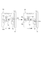
図3(b)に示すように、画像形成装置には前扉93を装置本体に対して開かないようにロックするロック手段を構成するロックユニット105が備えられている。一方、図4に示すように、前扉93には、前記ロックユニット105と対向する位置に、前記ロックユニット105と係合可能なフック部材102が設けられている。前扉93は、前扉93が閉められた状態でロックユニット105とフック部材102が係合することで、装置本体に対して前扉93が開かないようにロックがかけられる。
As shown in FIG. 3B, the image forming apparatus is provided with a
ロックユニット105には前扉93に備え付けられたフック部材102と対向する位置に、フック部材102に引っ掛かるように回動可能なロック部材103が設けられている。ロック部材103には、フック部材102と係合する係合部103aと、係合部103aに対して回動中心反対側に検知部103bが設けられている。ロック検知センサ104は前記ロック部材103の検知部103bを検知する検知手段である。このロック検知センサ104により前扉93がロックされているか否かを検知する構成となっている。
The
前扉93が閉められた状態でロックユニット105に設けられたソレノイド(以下SL)101がON/OFFすることで、ロック部材103を回動させて前扉93のロック状態、フリー状態を変更することができる。
When the solenoid (hereinafter referred to as SL) 101 provided in the
SL101がOFFの時、ロック部材103の係合部103aが回動して上側に逃げることで前扉93のフック部材との係合が解除され、前扉93がフリー状態になる。その時、ロック検知センサ104が検知部103bを検知できない状態となり、前扉93がロックされていないことを検知する。
When SL101 is OFF, the
逆にSL101がONの時は、ロック部材103の係合部103aが回動して下側に下がることで前扉93のフック部材102と係合し、前扉93がロック状態となる。その時、ロック検知センサ104が検知部103bを検知した状態となり、前扉93がロックされたことを検知する。
On the contrary, when SL101 is ON, the engaging
<ロック動作>
次に、前扉93のロック動作について説明する。前述したように画像形成を行うためにシート収納部から給送されたシートは、シート給送部92とシート搬送装置91とを通って排出積載部50へ排出される。この際に、シートの重送や不送りなどによってジャム(紙詰まり)が発生する可能性がある。
<Lock operation>
Next, the locking operation of the
本実施形態では、前記SL101等を含む画像形成装置の動作を制御する制御装置(不図示)が、シートを検出しているセンサ(不図示)からの情報に基づいて装置内に残っているシートの位置を検出し、前扉93をロックするか否かを判定している。
In this embodiment, a control device (not shown) that controls the operation of the image forming apparatus including the
例えば、シート先端が排出積載部50に到達し、その後端が内排出ローラ46よりもシート搬送方向上流にあるような時、つまりシートが引出ユニットであるシート搬送装置91と反転部58との間に跨っている状態のときに前扉93のロック処理を実行する。シートがシート搬送装置91と反転部58に跨った状態で、引出ユニットであるシート搬送装置91を装置本体から引き出すとシートが破断し、最悪の場合は装置の破損に繋がるからである。そのため、前扉93をロックして、シート搬送装置91を引き出せなくし、最初に搬送方向にある反転部58からシートを引き抜くことでシートへのダメージ、装置本体のダメージを低減することができる。
For example, when the leading end of the sheet reaches the
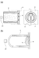
<ロック表示部>
次にロック状態を表示する表示部について図1、図5と用いて説明する。図1は、ロック表示94を説明する図であり、LED200と共に示している。図1(a)はロック表示のA−A断面図であり、図1(b)はロック表示の断面斜視図である。図5(a)は、ロック表示94を有する前扉93の斜視図である。図5(b)は、前扉93の正面側(装置外側)から見たロック表示94を示す平面図である。
<Lock display section>
Next, a display unit for displaying the lock state will be described with reference to FIGS. FIG. 1 is a diagram for explaining the
前述したように、シート搬送装置91を装置本体から引き出すことでシートへのダメージが懸念される場合には、前扉93がロック状態になり、ユーザが前扉93の開動作を行うことができない。このような装置の状態(ロックして前扉が開かいない状態)をユーザに知らせるため、前扉93にロック表示94を設け、それと対向する装置本体側にロック表示94を照射するLED200を設けている。ロック表示94は、外装部材としての前扉93に設けられ、前記前扉93のロック状態又はフリー状態を表示するための表示部である。LED200は、前記ロック表示94を点灯させるための光源である。また、ロック表示94とLED200の間には、LED200からの光を効率的にロック表示94に集めるための集光部95が前扉93に設けられている。
As described above, when there is concern about damage to the sheet by pulling out the
LED200の点灯に関しては、SL101がONしてロック検知センサ104が検知部103bを検知すると、不図示の制御装置によりLED200が点灯する。逆に、ジャム処理後、SL101がOFFとなりロック検知センサ104が検知部103bを検知できなくなると、前記制御装置によりLED200が消灯する。
Regarding the lighting of the
次にロック表示部の詳細な構成について図1、図5を用いて説明する。本実施形態ではロック表示94としては、前扉93のロック状態を表すために鍵マークのデザインとなっている。ロック表示94は、前扉93と同一部材であり、前扉93の内面(前扉93の外装面とは反対側の面)に、鍵マークのデザインがその他の面に対して一段凹んだ形状となっている。つまり、ロック表示94は、前扉93の一部である薄肉部である。ロック表示94としての薄肉部は、前扉93の肉厚(前扉93におけるロック表示94の他の部分の厚さ)とは異なる、前扉93の肉厚よりも薄い肉厚を有し、前扉93に鍵マークの形に形成されている。更に具体的には、ロック表示94の肉厚(薄肉部)は、前扉93の肉厚に対して半分以下である。そして、ロック表示94の凹み形状は、装置外からは見えない前扉93の内側のみ設けられており、装置本体の外装面には凹みが無い形状となっている。ロック表示94は前扉93の肉厚に比べて半分以下の肉厚(薄肉)に成形されているので、内側からLED200で照射すると薄肉の部分のみLED光が透過し、装置本体の前面から見るとロック表示94のみが見える。またロック表示94は、装置本体の外装面には凹みが無いため、LED200の消灯時には意匠性も損ねない。なお、ロック表示94(薄肉部)よりも厚い肉厚を備えている、前扉93におけるロック表示94の他の部分とは、LED光が照射される前扉93の領域内における、ロック表示94(薄肉部)以外の部分を、指している。
Next, a detailed configuration of the lock display unit will be described with reference to FIGS. In the present embodiment, the
本実施形態の場合、前扉93の材質はPC+ABSであり、難燃性を確保するために基本肉厚が2.0mmになっている。それに対してロック表示94は、前扉93と同一部材であり、前扉93の肉厚に比べて薄肉になっている。ロック表示94部分の肉厚は、極力薄い方がLED光が透過しやすいが、ここでは成形性などを考慮して0.6mmとしている。
In the case of this embodiment, the material of the
またロック表示94とLED200の間には集光部95が設けられている。集光部95は、LED200から出たLED光を効率的にロック表示94に集めるためのものである。集光部95は、ロック表示94の全周を囲むように設けられており、円筒状の集光部95を備えている。集光部95は、LED200とロック表示94とを結んだ線に沿って中心軸が延びた円筒形状である。少ないLED光量でロック表示94をより鮮明に光らせる(LEDを透過させる)には、集光部95の表面にLEDを反射させながらロック表示94に集光する必要がある。そのため、集光部95は反射率の高い色で形成されている。具体的には、集光部95のLED光が反射する面は、より多くのLED光が反射するように黒色系よりも白色系にするのが好ましい。集光部95が白色系なので、同一部材の前扉93も白色系にするのが製造上もっとも好ましいが、例えば二色成形などで前扉93と集光部95の色が異なっても問題ない。また、本実施形態ではLED200の光源が3mm四方に対して、集光部95は直径12mmとしている。
A condensing
このように、前扉93に薄肉のロック表示94を設けることで、LED200の消灯時には意匠性を確保しつつ、LED200が点灯したときのみ鍵マークを本体前面から視認することができる。また、外装部材である前扉93の内側の一部をロック表示94として薄肉にすることで、そこにLED光を照射させた場合にのみ表示部としての役割を果たす。これにより、表示部を外装部材に別途設ける必要がなく、LEDの消灯時には意匠性も損ねない構成とすることができる。
As described above, by providing the
なお、図3に示すように、前扉93はヒンジ部と反対側の端部に、前扉93を開くときにユーザが操作する取手201が設けられている。そして、ロック表示94は、取手201に近傍に配置されている。また、図3の202は、画像形成装置にユーザが設定を入力したりユーザへのメッセージを表示したりする操作表示部である。前扉93をロックしたときには、前扉93のロック表示94によってロック状態を知らせるだけでなく、操作表示部にも前扉93がロックされていることを知らせる表示が行なわれる。
As shown in FIG. 3, the
なお、前述した実施形態では、ロック表示94として鍵マークを例示した。しかし、例えば「ロック中」などの文字によって、前扉93がロックされていることを表示するようにしてもよい。また、前述した実施形態では前扉93がロックされているときにLEDを点灯させてロックしていること知らせる形態を例示した。しかし、前扉93がロックされていないときにLEDを点灯さてロック解除の状態(前扉93を開くことができる状態)であることを表示するようにしてもよい。
In the embodiment described above, the key mark is exemplified as the
また、前述した実施形態では、画像形成装置の状態を示す表示の一例として、前扉93のロック状態を示す形態を例示した。しかし、例えば、画像形成の動作中に「プリント中」を表示するようにしてもよい。この場合、画像の形成動作中に「プリント中」を表示させるためにLEDが点灯し、画像形成動作を行っていない待機中においてはLEDを消灯させる。
Further, in the above-described embodiment, as an example of the display indicating the state of the image forming apparatus, the form indicating the locked state of the
なお、前述した実施形態では、色の異なる4つの画像形成部を使用した画像形成装置を例示しているが、この画像形成部の使用個数はこれに限定されるものではなく、必要に応じて適宜設定すれば良い。 In the above-described embodiment, the image forming apparatus using four image forming units having different colors is illustrated. However, the number of the image forming units to be used is not limited to this and may be changed as necessary. What is necessary is just to set suitably.
また前述した実施形態では、画像形成装置として複写機を例示したが、本発明はこれに限定されるものではない。例えばプリンタ、ファクシミリ装置等の他の画像形成装置や、或いはこれらの機能を組み合わせた複合機等の他の画像形成装置であっても良い。また、中間転写体を使用し、該中間転写体に各色のトナー像を順次重ねて転写し、該中間転写体に担持されたトナー像をシートに一括して転写する画像形成装置を例示したが、これに限定されるものでもない。シート担持体を使用し、該シート担持体に担持されたシートに各色のトナー像を順次重ねて転写する画像形成装置であっても良い。また画像形成手段としてはインクジェット方式の画像形成手段であってもよい。これらの画像形成装置に本発明を適用することにより同様の効果を得ることができる。 In the above-described embodiment, the copying machine is exemplified as the image forming apparatus, but the present invention is not limited to this. For example, the image forming apparatus may be another image forming apparatus such as a printer or a facsimile apparatus, or another image forming apparatus such as a multi-function machine that combines these functions. Further, the image forming apparatus is exemplified in which an intermediate transfer member is used, toner images of respective colors are sequentially transferred onto the intermediate transfer member, and the toner images carried on the intermediate transfer member are collectively transferred to a sheet. However, the present invention is not limited to this. An image forming apparatus that uses a sheet carrier and sequentially superimposes and transfers the toner images of the respective colors on the sheet carried on the sheet carrier. The image forming unit may be an ink jet type image forming unit. The same effect can be obtained by applying the present invention to these image forming apparatuses.
S …シート
1 …画像形成装置
47 …両面搬送パス
58 …反転部
90 …画像形成部
91 …シート搬送装置
92 …シート給送部
93 …前扉
94 …ロック表示
95 …集光部
101 …ソレノイド
102 …フック部材
103 …ロック部材
103a …係合部
103b …検知部
104 …ロック検知センサ
105 …ロックユニット
200 …LED
S ... Sheet 1 ... Image forming apparatus 47 ... Double-
Claims (14)
前記外装部材を前記装置本体にロックするためのロック手段と、
前記外装部材に設けられ、前記ロック手段の状態を表示するための表示部と、
前記表示部を点灯させるための光源と、を有し、
前記表示部は、前記外装部材の一部であって、前記外装部材における他の部分の肉厚よりも薄い肉厚の、前記光源からの光が透過する薄肉部であることを特徴とする画像形成装置。 An exterior member that can be opened and closed in the apparatus body, and forms an exterior of the apparatus body;
Locking means for locking the exterior member to the apparatus main body;
A display unit provided on the exterior member for displaying the state of the locking means;
A light source for lighting the display unit,
The display section is a thin-walled portion that is a part of the exterior member and is thinner than the thickness of other portions of the exterior member and transmits light from the light source. Forming equipment.
前記画像形成装置の外装部材と、
前記画像形成装置の状態を表示するための表示部と、
前記表示部を点灯させるための光源と、を有し、
前記表示部は、前記外装部材の一部であって、前記外装部材における他の部分の厚さよりも薄い、前記光源からの光が透過する薄肉部であることを特徴とする画像形成装置。 An image forming apparatus,
An exterior member of the image forming apparatus;
A display unit for displaying a state of the image forming apparatus;
A light source for lighting the display unit,
The image forming apparatus according to claim 1, wherein the display unit is a thin-walled portion that is a part of the exterior member and is thinner than other portions of the exterior member and transmits light from the light source.
前記装置本体に前記光源が設けられ、前記外装部材に前記集光部が設けられていることを特徴とする請求項8乃至10のいずれか1項に記載の画像形成装置。 The exterior member is provided to be openable and closable on the apparatus body.
The image forming apparatus according to claim 8, wherein the light source is provided in the apparatus main body, and the light collecting unit is provided in the exterior member.
Priority Applications (2)
| Application Number | Priority Date | Filing Date | Title |
|---|---|---|---|
| JP2016136078A JP2018005182A (en) | 2016-07-08 | 2016-07-08 | Image forming apparatus |
| US15/641,606 US10167166B2 (en) | 2016-07-08 | 2017-07-05 | Image forming apparatus |
Applications Claiming Priority (1)
| Application Number | Priority Date | Filing Date | Title |
|---|---|---|---|
| JP2016136078A JP2018005182A (en) | 2016-07-08 | 2016-07-08 | Image forming apparatus |
Publications (2)
| Publication Number | Publication Date |
|---|---|
| JP2018005182A true JP2018005182A (en) | 2018-01-11 |
| JP2018005182A5 JP2018005182A5 (en) | 2019-08-15 |
Family
ID=60893126
Family Applications (1)
| Application Number | Title | Priority Date | Filing Date |
|---|---|---|---|
| JP2016136078A Pending JP2018005182A (en) | 2016-07-08 | 2016-07-08 | Image forming apparatus |
Country Status (2)
| Country | Link |
|---|---|
| US (1) | US10167166B2 (en) |
| JP (1) | JP2018005182A (en) |
Cited By (1)
| Publication number | Priority date | Publication date | Assignee | Title |
|---|---|---|---|---|
| US11762325B2 (en) | 2021-04-23 | 2023-09-19 | Canon Kabushiki Kaisha | Image forming apparatus |
Families Citing this family (3)
| Publication number | Priority date | Publication date | Assignee | Title |
|---|---|---|---|---|
| JP6859038B2 (en) * | 2016-07-12 | 2021-04-14 | キヤノン株式会社 | Image forming device |
| JP2021142732A (en) * | 2020-03-13 | 2021-09-24 | キヤノン株式会社 | Image forming apparatus |
| US11427417B2 (en) * | 2020-08-05 | 2022-08-30 | Konica Minolta, Inc. | Image forming device |
Citations (9)
| Publication number | Priority date | Publication date | Assignee | Title |
|---|---|---|---|---|
| US4176941A (en) * | 1978-02-27 | 1979-12-04 | Van Dyk Research Corporation | Malfunction display system for electrophotographic copying machines |
| JPH05289446A (en) * | 1992-04-10 | 1993-11-05 | Ricoh Co Ltd | Image forming device |
| JPH09212114A (en) * | 1996-01-31 | 1997-08-15 | Nippon Seiki Co Ltd | Display device |
| JP2000011794A (en) * | 1998-06-23 | 2000-01-14 | Sanyo Electric Co Ltd | Push button |
| JP2008076837A (en) * | 2006-09-22 | 2008-04-03 | Konica Minolta Business Technologies Inc | Image forming apparatus |
| JP2010039391A (en) * | 2008-08-07 | 2010-02-18 | Kyocera Mita Corp | Image forming device |
| JP2012088646A (en) * | 2010-10-22 | 2012-05-10 | Fuji Xerox Co Ltd | Operation device and image forming apparatus |
| JP2015215633A (en) * | 2015-08-26 | 2015-12-03 | 京セラドキュメントソリューションズ株式会社 | Image forming apparatus |
| JP2016057351A (en) * | 2014-09-05 | 2016-04-21 | シャープ株式会社 | Image forming apparatus and image forming system using the same |
Family Cites Families (10)
| Publication number | Priority date | Publication date | Assignee | Title |
|---|---|---|---|---|
| US5157448A (en) * | 1992-04-16 | 1992-10-20 | Xerox Corporation | Automatic copier or printer paper tray lock |
| US7403721B2 (en) * | 2006-02-28 | 2008-07-22 | Kabushiki Kaisha Toshiba | Image forming apparatus, MFP and method of displaying jam removal guidance |
| JP5777019B2 (en) | 2011-03-14 | 2015-09-09 | 株式会社リコー | Light emitting part structure of equipment, equipment using the same, and image forming apparatus |
| JP2013018586A (en) * | 2011-07-08 | 2013-01-31 | Ricoh Co Ltd | Sheet tray and image forming apparatus |
| JP2013133214A (en) * | 2011-12-27 | 2013-07-08 | Canon Inc | Sheet conveying device and image forming apparatus |
| JP6057162B2 (en) * | 2012-12-13 | 2017-01-11 | 株式会社リコー | Image forming apparatus |
| JP2014119511A (en) * | 2012-12-13 | 2014-06-30 | Ricoh Co Ltd | Image forming apparatus |
| JP2014134753A (en) * | 2012-12-13 | 2014-07-24 | Ricoh Co Ltd | Image forming apparatus |
| US9533846B2 (en) * | 2015-01-30 | 2017-01-03 | Ricoh Company, Ltd. | Drawer unit, and image forming apparatus using the drawer unit |
| US9561920B1 (en) * | 2015-10-01 | 2017-02-07 | Xerox Corporation | Media supply tray having multi-color exterior light indicating different media loading conditions |
-
2016
- 2016-07-08 JP JP2016136078A patent/JP2018005182A/en active Pending
-
2017
- 2017-07-05 US US15/641,606 patent/US10167166B2/en active Active
Patent Citations (9)
| Publication number | Priority date | Publication date | Assignee | Title |
|---|---|---|---|---|
| US4176941A (en) * | 1978-02-27 | 1979-12-04 | Van Dyk Research Corporation | Malfunction display system for electrophotographic copying machines |
| JPH05289446A (en) * | 1992-04-10 | 1993-11-05 | Ricoh Co Ltd | Image forming device |
| JPH09212114A (en) * | 1996-01-31 | 1997-08-15 | Nippon Seiki Co Ltd | Display device |
| JP2000011794A (en) * | 1998-06-23 | 2000-01-14 | Sanyo Electric Co Ltd | Push button |
| JP2008076837A (en) * | 2006-09-22 | 2008-04-03 | Konica Minolta Business Technologies Inc | Image forming apparatus |
| JP2010039391A (en) * | 2008-08-07 | 2010-02-18 | Kyocera Mita Corp | Image forming device |
| JP2012088646A (en) * | 2010-10-22 | 2012-05-10 | Fuji Xerox Co Ltd | Operation device and image forming apparatus |
| JP2016057351A (en) * | 2014-09-05 | 2016-04-21 | シャープ株式会社 | Image forming apparatus and image forming system using the same |
| JP2015215633A (en) * | 2015-08-26 | 2015-12-03 | 京セラドキュメントソリューションズ株式会社 | Image forming apparatus |
Cited By (1)
| Publication number | Priority date | Publication date | Assignee | Title |
|---|---|---|---|---|
| US11762325B2 (en) | 2021-04-23 | 2023-09-19 | Canon Kabushiki Kaisha | Image forming apparatus |
Also Published As
| Publication number | Publication date |
|---|---|
| US20180009625A1 (en) | 2018-01-11 |
| US10167166B2 (en) | 2019-01-01 |
Similar Documents
| Publication | Publication Date | Title |
|---|---|---|
| JP5523216B2 (en) | Image forming apparatus | |
| JP2018005182A (en) | Image forming apparatus | |
| JP2007047571A (en) | Image forming device | |
| US8442418B2 (en) | Image forming apparatus having door to access jammed sheets | |
| JP5675709B2 (en) | Sheet conveying apparatus and image forming apparatus | |
| JP4873487B2 (en) | Image forming apparatus | |
| US8985568B2 (en) | Paper discharge device of image forming apparatus | |
| JP2015163960A (en) | image forming apparatus | |
| JP2010284823A (en) | Lock mechanism of opening and closing cover and image forming apparatus | |
| JP6587513B2 (en) | Image forming apparatus | |
| JP2008083442A (en) | Image forming apparatus | |
| US10254688B2 (en) | Image forming apparatus with pivoting fixing device | |
| JP6463239B2 (en) | Sheet conveying apparatus and image forming apparatus. | |
| JP6287981B2 (en) | Image forming apparatus | |
| JP2016098052A (en) | Recording medium conveyance device and image formation apparatus | |
| JP2014046998A (en) | Sheet conveying device, and image forming apparatus with the same | |
| JP6685746B2 (en) | Image forming apparatus and image forming system | |
| JP6849332B2 (en) | Image forming device and image forming system | |
| JP5328523B2 (en) | Sheet conveying apparatus and image forming apparatus | |
| US20110062649A1 (en) | Sheet feeding device and image forming apparatus having same | |
| JP2015069068A (en) | Image forming apparatus | |
| JP5049511B2 (en) | Lock device and image forming apparatus | |
| US8837987B2 (en) | Image forming apparatus with first and second interlocking doors | |
| JP2008100816A (en) | Image forming device | |
| JP2001235905A (en) | Image forming device |
Legal Events
| Date | Code | Title | Description |
|---|---|---|---|
| A521 | Request for written amendment filed |
Free format text: JAPANESE INTERMEDIATE CODE: A523 Effective date: 20190704 |
|
| A621 | Written request for application examination |
Free format text: JAPANESE INTERMEDIATE CODE: A621 Effective date: 20190704 |
|
| A977 | Report on retrieval |
Free format text: JAPANESE INTERMEDIATE CODE: A971007 Effective date: 20200630 |
|
| A131 | Notification of reasons for refusal |
Free format text: JAPANESE INTERMEDIATE CODE: A131 Effective date: 20200714 |
|
| A521 | Request for written amendment filed |
Free format text: JAPANESE INTERMEDIATE CODE: A523 Effective date: 20200903 |
|
| A131 | Notification of reasons for refusal |
Free format text: JAPANESE INTERMEDIATE CODE: A131 Effective date: 20210119 |
|
| A521 | Request for written amendment filed |
Free format text: JAPANESE INTERMEDIATE CODE: A523 Effective date: 20210312 |
|
| A02 | Decision of refusal |
Free format text: JAPANESE INTERMEDIATE CODE: A02 Effective date: 20210720 |