JP2017538526A - Adapter for robot cannula and sealing assembly - Google Patents
Adapter for robot cannula and sealing assembly Download PDFInfo
- Publication number
- JP2017538526A JP2017538526A JP2017532976A JP2017532976A JP2017538526A JP 2017538526 A JP2017538526 A JP 2017538526A JP 2017532976 A JP2017532976 A JP 2017532976A JP 2017532976 A JP2017532976 A JP 2017532976A JP 2017538526 A JP2017538526 A JP 2017538526A
- Authority
- JP
- Japan
- Prior art keywords
- cannula
- sealing assembly
- proximal
- tapered surface
- annular flange
- Prior art date
- Legal status (The legal status is an assumption and is not a legal conclusion. Google has not performed a legal analysis and makes no representation as to the accuracy of the status listed.)
- Granted
Links
- 238000007789 sealing Methods 0.000 title claims abstract description 107
- 230000000295 complement effect Effects 0.000 claims abstract description 18
- 239000013536 elastomeric material Substances 0.000 claims description 23
- 239000012530 fluid Substances 0.000 claims description 19
- 239000000463 material Substances 0.000 claims description 9
- 238000004891 communication Methods 0.000 claims description 8
- 238000003780 insertion Methods 0.000 claims description 4
- 230000037431 insertion Effects 0.000 claims description 4
- 238000000034 method Methods 0.000 description 8
- 238000001356 surgical procedure Methods 0.000 description 6
- 229920003023 plastic Polymers 0.000 description 5
- 239000004033 plastic Substances 0.000 description 5
- 230000008878 coupling Effects 0.000 description 4
- 238000010168 coupling process Methods 0.000 description 4
- 238000005859 coupling reaction Methods 0.000 description 4
- 238000012986 modification Methods 0.000 description 4
- 230000004048 modification Effects 0.000 description 4
- 238000004140 cleaning Methods 0.000 description 3
- 239000012636 effector Substances 0.000 description 3
- 230000000694 effects Effects 0.000 description 3
- 238000002674 endoscopic surgery Methods 0.000 description 3
- 230000014509 gene expression Effects 0.000 description 3
- 230000035515 penetration Effects 0.000 description 3
- 230000005855 radiation Effects 0.000 description 3
- CURLTUGMZLYLDI-UHFFFAOYSA-N Carbon dioxide Chemical compound O=C=O CURLTUGMZLYLDI-UHFFFAOYSA-N 0.000 description 2
- 208000005646 Pneumoperitoneum Diseases 0.000 description 2
- 229920001971 elastomer Polymers 0.000 description 2
- 239000000806 elastomer Substances 0.000 description 2
- 230000007246 mechanism Effects 0.000 description 2
- 238000002324 minimally invasive surgery Methods 0.000 description 2
- 241000272525 Anas platyrhynchos Species 0.000 description 1
- 241000894006 Bacteria Species 0.000 description 1
- 208000032544 Cicatrix Diseases 0.000 description 1
- IAYPIBMASNFSPL-UHFFFAOYSA-N Ethylene oxide Chemical compound C1CO1 IAYPIBMASNFSPL-UHFFFAOYSA-N 0.000 description 1
- 229920003295 Radel® Polymers 0.000 description 1
- 229920000690 Tyvek Polymers 0.000 description 1
- 239000004775 Tyvek Substances 0.000 description 1
- 230000006978 adaptation Effects 0.000 description 1
- 238000013459 approach Methods 0.000 description 1
- 229910002092 carbon dioxide Inorganic materials 0.000 description 1
- 239000001569 carbon dioxide Substances 0.000 description 1
- 238000010276 construction Methods 0.000 description 1
- 238000010894 electron beam technology Methods 0.000 description 1
- 238000007667 floating Methods 0.000 description 1
- 208000015181 infectious disease Diseases 0.000 description 1
- 208000014674 injury Diseases 0.000 description 1
- 238000012423 maintenance Methods 0.000 description 1
- 238000012978 minimally invasive surgical procedure Methods 0.000 description 1
- 229920002492 poly(sulfone) Polymers 0.000 description 1
- 230000008569 process Effects 0.000 description 1
- 238000011084 recovery Methods 0.000 description 1
- 238000002432 robotic surgery Methods 0.000 description 1
- 231100000241 scar Toxicity 0.000 description 1
- 230000037387 scars Effects 0.000 description 1
- 230000003068 static effect Effects 0.000 description 1
- 230000001954 sterilising effect Effects 0.000 description 1
- 238000004659 sterilization and disinfection Methods 0.000 description 1
- 239000013589 supplement Substances 0.000 description 1
- 230000004083 survival effect Effects 0.000 description 1
- 238000002560 therapeutic procedure Methods 0.000 description 1
- 230000008733 trauma Effects 0.000 description 1
- XLYOFNOQVPJJNP-UHFFFAOYSA-N water Chemical compound O XLYOFNOQVPJJNP-UHFFFAOYSA-N 0.000 description 1
Images


Classifications
-
- A—HUMAN NECESSITIES
- A61—MEDICAL OR VETERINARY SCIENCE; HYGIENE
- A61B—DIAGNOSIS; SURGERY; IDENTIFICATION
- A61B17/00—Surgical instruments, devices or methods
- A61B17/34—Trocars; Puncturing needles
- A61B17/3462—Trocars; Puncturing needles with means for changing the diameter or the orientation of the entrance port of the cannula, e.g. for use with different-sized instruments, reduction ports, adapter seals
-
- A—HUMAN NECESSITIES
- A61—MEDICAL OR VETERINARY SCIENCE; HYGIENE
- A61B—DIAGNOSIS; SURGERY; IDENTIFICATION
- A61B17/00—Surgical instruments, devices or methods
- A61B17/34—Trocars; Puncturing needles
- A61B17/3417—Details of tips or shafts, e.g. grooves, expandable, bendable; Multiple coaxial sliding cannulas, e.g. for dilating
- A61B17/3421—Cannulas
-
- A—HUMAN NECESSITIES
- A61—MEDICAL OR VETERINARY SCIENCE; HYGIENE
- A61M—DEVICES FOR INTRODUCING MEDIA INTO, OR ONTO, THE BODY; DEVICES FOR TRANSDUCING BODY MEDIA OR FOR TAKING MEDIA FROM THE BODY; DEVICES FOR PRODUCING OR ENDING SLEEP OR STUPOR
- A61M39/00—Tubes, tube connectors, tube couplings, valves, access sites or the like, specially adapted for medical use
- A61M39/22—Valves or arrangement of valves
- A61M39/26—Valves closing automatically on disconnecting the line and opening on reconnection thereof
-
- A—HUMAN NECESSITIES
- A61—MEDICAL OR VETERINARY SCIENCE; HYGIENE
- A61B—DIAGNOSIS; SURGERY; IDENTIFICATION
- A61B17/00—Surgical instruments, devices or methods
- A61B2017/00477—Coupling
-
- A—HUMAN NECESSITIES
- A61—MEDICAL OR VETERINARY SCIENCE; HYGIENE
- A61B—DIAGNOSIS; SURGERY; IDENTIFICATION
- A61B17/00—Surgical instruments, devices or methods
- A61B2017/00477—Coupling
- A61B2017/00486—Adaptors for coupling parts with incompatible geometries
-
- A—HUMAN NECESSITIES
- A61—MEDICAL OR VETERINARY SCIENCE; HYGIENE
- A61B—DIAGNOSIS; SURGERY; IDENTIFICATION
- A61B17/00—Surgical instruments, devices or methods
- A61B17/34—Trocars; Puncturing needles
- A61B17/3417—Details of tips or shafts, e.g. grooves, expandable, bendable; Multiple coaxial sliding cannulas, e.g. for dilating
- A61B17/3421—Cannulas
- A61B17/3439—Cannulas with means for changing the inner diameter of the cannula, e.g. expandable
- A61B2017/3441—Cannulas with means for changing the inner diameter of the cannula, e.g. expandable with distal sealing means
-
- A—HUMAN NECESSITIES
- A61—MEDICAL OR VETERINARY SCIENCE; HYGIENE
- A61B—DIAGNOSIS; SURGERY; IDENTIFICATION
- A61B17/00—Surgical instruments, devices or methods
- A61B17/34—Trocars; Puncturing needles
- A61B17/3462—Trocars; Puncturing needles with means for changing the diameter or the orientation of the entrance port of the cannula, e.g. for use with different-sized instruments, reduction ports, adapter seals
- A61B2017/3464—Trocars; Puncturing needles with means for changing the diameter or the orientation of the entrance port of the cannula, e.g. for use with different-sized instruments, reduction ports, adapter seals with means acting on inner surface of valve or seal for expanding or protecting, e.g. inner pivoting fingers
-
- A—HUMAN NECESSITIES
- A61—MEDICAL OR VETERINARY SCIENCE; HYGIENE
- A61B—DIAGNOSIS; SURGERY; IDENTIFICATION
- A61B34/00—Computer-aided surgery; Manipulators or robots specially adapted for use in surgery
- A61B34/30—Surgical robots
Landscapes
- Health & Medical Sciences (AREA)
- Life Sciences & Earth Sciences (AREA)
- Surgery (AREA)
- Heart & Thoracic Surgery (AREA)
- Public Health (AREA)
- Animal Behavior & Ethology (AREA)
- Biomedical Technology (AREA)
- Veterinary Medicine (AREA)
- Engineering & Computer Science (AREA)
- General Health & Medical Sciences (AREA)
- Medical Informatics (AREA)
- Molecular Biology (AREA)
- Pathology (AREA)
- Nuclear Medicine, Radiotherapy & Molecular Imaging (AREA)
- Pulmonology (AREA)
- Anesthesiology (AREA)
- Hematology (AREA)
- Surgical Instruments (AREA)
Abstract
アダプター装置は、封止アセンブリハウジング、チャネル、及びテーパ形状表面を備える。アダプター装置は、トロカール封止アセンブリをロボットトロカールカニューレと接続して、患者の吹送された体腔内のニューモスタシスを維持するように構成されている。封止アセンブリハウジングは、アダプター装置内にトロカール封止アセンブリを受け入れ、支持し、かつ固定するのに十分な開放面積を備える。チャネルは、器具をトロカール封止アセンブリからカニューレの中に挿入するための経路を提供する。ロボットトロカールカニューレは、環状フランジと、テーパ形状近位開口部とを含む。アダプター装置のテーパ形状表面は、カニューレの環状フランジ及びテーパ形状近位開口部に係合するように構成されている。アダプター装置のテーパ形状表面は、カニューレの環状フランジの外側及び角度をなした開口部を補完するように構成されている。The adapter device includes a sealed assembly housing, a channel, and a tapered surface. The adapter device is configured to connect the trocar seal assembly with the robot trocar cannula to maintain pneumostosis within the patient's insufflated body cavity. The sealing assembly housing has an open area sufficient to receive, support and secure the trocar sealing assembly within the adapter device. The channel provides a path for inserting the instrument from the trocar seal assembly into the cannula. The robot trocar cannula includes an annular flange and a tapered proximal opening. The tapered surface of the adapter device is configured to engage the annular flange and the tapered proximal opening of the cannula. The tapered surface of the adapter device is configured to complement the outside and angled opening of the annular flange of the cannula.
Description
外科手術において内視鏡手技が使用され得る。用語「内視鏡の」は、腹腔鏡手技及び関節鏡手技を含むあらゆるタイプの低侵襲性外科手技を指す。内視鏡手術は、開腹手術に比べて、外傷の減少、より速い回復、感染のリスクの減少、及び瘢痕の減少を提供し得る。 Endoscopic procedures can be used in surgery. The term “endoscopic” refers to any type of minimally invasive surgical procedure, including laparoscopic and arthroscopic procedures. Endoscopic surgery can provide reduced trauma, faster recovery, reduced risk of infection, and reduced scars compared to open surgery.
内視鏡器具を体腔内に導入するために、「トロカール」として知られる装置を用いて、体腔の壁を穿刺し及び/又は体腔の壁をカニューレ処置することができる。トロカールは、栓子とカニューレとを備えることができる。栓子は、体腔壁の貫通を容易にする鋭くとがった又は適切に構造化された先端部を含むことができる。カニューレは、外科医がそれを通して内視鏡器具を導入し、また除去することが可能な、体腔壁を貫くチャネル又は開口部を提供する。 To introduce an endoscopic instrument into a body cavity, a device known as a “trocar” can be used to puncture and / or cannulate the body cavity wall. The trocar can comprise an obturator and a cannula. The obturator can include a sharply pointed or appropriately structured tip that facilitates penetration of the body cavity wall. The cannula provides a channel or opening through the body cavity wall through which the surgeon can introduce and remove endoscopic instruments.
内視鏡手術は、目的とする外科手技を行うのに十分な空間を与えるための、二酸化炭素などの、吹送流体が体腔内に存在する状態で行なわれ得る。吹送された体腔は一般に圧力下にあり、ときに気腹状態にあると称される。気腹状態を維持するために、封止部若しくは封止機構が、カニューレと一体的に形成され得るか、又はカニューレに直接取り付け可能であり得る。封止部は、一般的に、内視鏡器具がトロカールカニューレに位置付けられ得る間に、吹送流体が漏出することを防止する。 Endoscopic surgery can be performed with insufflation fluid, such as carbon dioxide, in the body cavity to provide sufficient space to perform the intended surgical procedure. Insufflated body cavities are generally under pressure and are sometimes referred to as being in the pneumoperitoneum. In order to maintain a pneumoperitoneum, a seal or a sealing mechanism can be formed integrally with the cannula or can be directly attached to the cannula. The seal generally prevents insufflation fluid from leaking while the endoscopic instrument can be positioned on the trocar cannula.
トロカール及び関連デバイスのいくつかの実施例は、その開示内容が参照により本明細書に組み込まれる、1995年1月31日に発行された「Trocar with Floating Septum Seal」と題する米国特許第5,385,553号、その開示内容が参照により本明細書に組み込まれる、1997年5月13日に発行された「Trocar with Improved Universal Seal」と題する米国特許第5,628,732号、その開示内容が参照により本明細書に組み込まれる、1998年1月20日に発行された「Trocar Having an Improved Tip Configuration」と題する米国特許第5,709,671号、その開示内容が参照により本明細書に組み込まれる、1995年1月31日に発行された「Trocar for Endoscopic Surgery」と題する米国特許第5,385,572号、その開示内容が参照により本明細書に組み込まれる、1997年3月11日に発行された「Trocar with Improved Blade Attachment」と題する米国特許第5,609,604号、その開示内容が参照により本明細書に組み込まれる、1997年12月16日に発行された「Trocar Including Cannula with Stepped Region」と題する米国特許第5,697,913号、その開示内容が参照により本明細書に組み込まれる、1998年10月6日に発行された「rocar Assembly」と題する米国特許第5,817,061号、その開示内容が参照により本明細書に組み込まれる、1995年9月12日に発行のされた「Blunt Tipped Ultrasonic Trocar」と題する米国特許第5,449,370号、その開示内容が参照により本明細書に組み込まれる、2012年7月17日に発行された「Trocar Obturator」と題する米国特許第8,221,364号、及び2014年5月20日に発行された「Pleated Trocar Seal」と題する米国特許第8,728,037号に開示されている。 Some examples of trocars and related devices are described in US Pat. No. 5,385, entitled “Trocar with Floating Septum Seal,” issued January 31, 1995, the disclosure of which is incorporated herein by reference. , 553, the disclosure of which is incorporated herein by reference, U.S. Pat. No. 5,628,732, entitled “Trocar with Improved Universal Seal,” issued May 13, 1997, which is incorporated herein by reference. US Pat. No. 5,709,671, entitled “Trocar Having an Improved Tip Configuration” issued January 20, 1998, which is incorporated herein by reference, the disclosure of which is hereby incorporated by reference. U.S. Pat. No. 5,385,572 entitled “Trocar for Endoscopic Surgery” issued January 31, 1995, the disclosure of which is incorporated herein by reference, March 11, 1997 U.S. Pat. No. 5,609,604 entitled “Trocar with Improved Blade Attachment” issued on Dec. 16, “Trocar Inclusion” issued Dec. 16, 1997, the disclosure of which is incorporated herein by reference. U.S. Pat. No. 5,697,913 entitled “Canula with Stepped Region”, entitled “rocar Assembly” published on October 6, 1998, the disclosure of which is incorporated herein by reference. U.S. Pat. No. 5,817,061, U.S. Pat. No. 5,449, entitled “Blunt Tipped Ultrasonic Trocar,” issued September 12, 1995, the disclosure of which is incorporated herein by reference. No. 370, US Pat. No. 8,221,364 entitled “Trocar Observer”, issued July 17, 2012, the disclosure of which is incorporated herein by reference, and May 20, 2014 U.S. Pat. No. 8,728,037 entitled “Pleated Trocar Seal”.
いくつかの手術システムにより手術器具のロボット制御が提供される。低侵襲性ロボット手術では、外科手術は、患者の体内の小さな切開部を通じて実施され得る。ロボット手術システムでは、種々のタイプの手術器具と共に使用することができ、手術器具には、手術ステープラー、超音波器具、電気手術器具、及び/又は種々の他の種類の器具が挙げられるが、それらに限定されず、下記により詳細に説明する。ロボット手術システムの一例は、Intuitive Surgical,Inc.(Sunnyvale、California)によるDAVINCI(商標)システムである。更なる例として、ロボット手術システムの1つ又は2つ以上の態様が、以下に開示されている。その開示内容が参照により本明細書に組み込まれる、1998年8月11日に発行された「Articulated Surgical Instrument For Performing Minimally Invasive Surgery With Enhanced Dexterity and Sensitivity」と題する米国特許第5,792,135号、その開示内容が参照により本明細書に組み込まれる、1998年10月6日に発行された「Remote Center Positioning Device with Flexible Drive」と題する米国特許第5,817,084号、その開示内容が参照により本明細書に組み込まれる、1999年3月2日に発行された「Automated Endoscope System for Optimal Positioning」と題する米国特許第5,878,193号、その開示内容が参照により本明細書に組み込まれる、2001年5月15日に発行された「Robotic Arm DLUS for Performing Surgical Tasks」と題する米国特許第6,231,565号、その開示内容が参照により本明細書に組み込まれる、2004年8月31日に発行された「Robotic Surgical Tool with Ultrasound Cauterizing and Cutting Instrument」と題する米国特許第6,783,524号、その開示内容が参照により本明細書に組み込まれる、2002年4月2日に発行された「Alignment of Master and Slave in a Minimally Invasive Surgical Apparatus」と題する米国特許第6,364,888号、その開示内容が参照により本明細書に組み込まれる、2009年4月28日に発行された「Mechanical Actuator Interface System for Robotic Surgical Tools」と題する米国特許第7,524,320号、その開示内容が参照により本明細書に組み込まれる、2010年4月6日に発行された「Platform Link Wrist Mechanism」と題する米国特許第7,691,098号、その開示内容が参照により本明細書に組み込まれる、2010年10月5日に発行された「Repositioning and Reorientation of Master/Slave Relationship in Minimally Invasive Telesurgery」と題する米国特許第7,806,891号、及びその開示内容が参照により本明細書に組み込まれる、2010年11月2日に発行された「Surgical Tool With Writed Monopolar Electrosurgical End Effectors」と題する米国特許第7,824,401号。 Several surgical systems provide robotic control of surgical instruments. In minimally invasive robotic surgery, the surgery can be performed through a small incision in the patient's body. A robotic surgical system can be used with various types of surgical instruments, including surgical staplers, ultrasonic instruments, electrosurgical instruments, and / or various other types of instruments, However, the present invention will be described in detail below. An example of a robotic surgical system is available from Intuitive Surgical, Inc. (Sunnyvale, Calif.) DAVINCI ™ system. As a further example, one or more aspects of a robotic surgical system are disclosed below. "Articulated Surgical Instrument For Performing Minimally Innovative Survival With Enhanced Entitlement 5, Patent No. 135 and U.S. Patent No. 135, published on August 11, 1998, the disclosure of which is incorporated herein by reference" US Pat. No. 5,817,084 entitled “Remote Center Positioning Device with Flexible Drive” issued on Oct. 6, 1998, the disclosure of which is incorporated herein by reference. “Automated” issued March 2, 1999, incorporated herein. US Pat. No. 5,878,193 entitled “ndoscope System for Optimal Positioning”, the disclosure of which is hereby incorporated by reference, “Robotic Arm DLUS for Performing Surgical Task”. US Patent No. 6,231,565 entitled "Robotic Surgical Tool With Ultrasounding and Cutting Instrument" issued August 31, 2004, the disclosure of which is incorporated herein by reference. No. 6,783,524, issued April 2, 2002, the disclosure of which is incorporated herein by reference. US Pat. No. 6,364,888 entitled “Alignment of Master and Slave in a Minimal Inverse Surgical Apparatus”, the disclosure of which is incorporated herein by reference, issued April 28, 2009 US Pat. No. 7,524,320 entitled “Mechanical Actuator Interface System for Robotic Surgical Tools”, the disclosure of which is hereby incorporated herein by reference, “Platform LinkMrchMrMwMrW”, published on Apr. 6, 2010. US Pat. No. 7,691,098, the disclosure of which is incorporated herein by reference, 2010 U.S. Patent No. 7,806,891 issued October 5, entitled "Repositioning and Reorientation of Master / Slave Relationship in Minimally Investive Therapy", and its disclosure is incorporated herein by reference, 20 U.S. Pat. No. 7,824,401, entitled “Surgical Tool With Written Monopolar Electrical End Effects”, issued November 2.
ロボット手術システムと共に組み込むことができる器具のさらなる例が以下に記載される。その開示が参照により本明細書に組み込まれる、2013年1月10日に公開された「Automated End Effector Component Reloading System for Use with a Robotic System」と題する米国特許出願公開第2013/0012957号、その開示が参照により本明細書に組み込まれる、2012年8月9日に公開された「Robotically−Controlled Surgical Instrument with Force−Feedback Capabilities」とする米国特許出願公開第2012/0199630号、その開示が参照により本明細書に組み込まれる、2012年5月31日に公開された「Shiftable Drive Interface for Robotically−Controlled Surgical Tool」と題する米国特許出願公開第2012/0132450号、その開示が参照により本明細書に組み込まれる、2012年8月9日に公開された「Surgical Stapling Instruments with Cam−Driven Staple Deployment Arrangements」と題する米国特許出願公開第2012/0199633号、その開示が参照により本明細書に組み込まれる、2012年8月9日に公開された「Robotically−Controlled Motorized Surgical End Effector System with Rotary Actuated Closure Systems Having Variable Actuation Speeds」と題する米国特許出願公開第2012/0199631号、その開示が参照により本明細書に組み込まれる、2012年8月9日に公開された「Robotically−Controlled Surgical Instrument with Selectively Articulatable End Effector」と題する米国特許出願公開第2012/0199632号、その開示が参照により本明細書に組み込まれる、2012年8月9日に公開された「Robotically−Controlled Surgical End Effector System」と題する米国特許出願公開第2012/0203247号、2012年8月23日に公開された「Drive Interface for Operably Coupling a Manipulatable Surgical Tool to a Robot」と題する米国特許出願公開第2012/0211546号、その開示が参照により本明細書に組み込まれる、2012年6月7日に公開された「Robotically−Controlled Cable−Based Surgical End Effectors」と題する米国特許出願公開第2012/0138660号、その開示内容が参照により本明細書に組み込まれる、2012年8月16日に公開された「Robotically−Controlled Surgical End Effector System with Rotary Actuated Closure Systems」と題する米国特許出願公開第2012/0205421号、(、その開示内容が参照により本明細書に組み込まれる、2012年4月10日に出願された「Control Interface for Laparoscopic Suturing Instrument」と題する米国特許出願第13/443,101号、その開示内容が参照により本明細書に組み込まれる、2012年2月10日に出願された「Robotically Controlled Surgical Instrument」と題する米国仮特許出願第61/597,603号。 Additional examples of instruments that can be incorporated with the robotic surgical system are described below. US Patent Application Publication No. 2013/0012957, entitled “Automated End Effector Component Reloading System for Use with a Robotic System,” published January 10, 2013, the disclosure of which is incorporated herein by reference. U.S. Patent Application Publication No. 2012/0199630, entitled “Robotically-Controlled Surgical Instrument with Force-Feedback Capabilities” published August 9, 2012, which is incorporated herein by reference. “Shiftable Drive” published May 31, 2012, incorporated herein by reference. US Patent Application Publication No. 2012/0132450 entitled “E Interface for Robotically-Controlled Surgical Tool”, “Surgent Stapling Instruments, published on August 9, 2012, the disclosure of which is incorporated herein by reference. US Patent Application Publication No. 2012/0199633 entitled “Driving Stable Deployment Arrangements”, the disclosure of which is hereby incorporated by reference, “Robotically-Controlled Rigidly Protected Motorized Protected Motorized Protected Motorized Protected Motorized Measured Measured Measure Actuat U.S. Patent Application Publication No. 2012/0199631 entitled "Ed Closure Systems Having Variable Actuation Speeds", the disclosure of which is hereby incorporated by reference, "Robotically-Controlled Innovative Stable Measured Stable Measured US Patent Application Publication No. 2012/0199632 entitled “Articulatable End Effector”, the disclosure of which is incorporated herein by reference, “Robotically-Controlled Surgical End Effector System”, published August 9, 2012. Patent Application Publication No. 2012 / No. 0203247, U.S. Patent Application Publication No. 2012/0211546, the disclosure of which is incorporated herein by reference, “Drive Interface for Operable Coupling a Manipulable Surgical Tool to a Robot” published August 23, 2012, the disclosure of which is incorporated herein by reference. US Patent Application Publication No. 2012/0138660 entitled “Robotically-Controlled Cable-Based Surgical End Effects” published on June 7, 2012, the disclosure of which is incorporated herein by reference, 2012 “Robotically-Controlled Surgical End Effect” released on May 16 U.S. Patent Application Publication No. 2012/0205421, entitled “System with Rotated Actuation Closure Systems,” (the “Control Interface for Laparos Corporatory Corporatory Corporatory Corporatory Corporatory Corporatory Corporatory Corporatory Corporatory Corporatory Corporatory, filed on Apr. 10, 2012, the disclosure of which is incorporated herein by reference.” US Patent Application No. 13 / 443,101 entitled “Instrument”, US Provisional Patent Application entitled “Robotically Controlled Surgical Instrument” filed on February 10, 2012, the disclosure of which is incorporated herein by reference. 61 / 597,603.
ロボット手術システムで使用するために作製される、モジュラートロカール封止アセンブリをトロカールカニューレと連結するためのアダプターを提供することが望ましい場合がある。 It may be desirable to provide an adapter for coupling a modular trocar seal assembly made with a trocar cannula for use in a robotic surgical system.
本明細書に組み込まれると共にその一部をなす添付の図面は、本発明の実施形態を示すものであり、上記の本発明の一般的説明、及び以下の実施形態の詳細な説明と共に、本発明の原理を説明する役割を果たすものである。
図面は、いかなる方式でも限定すること意図されておらず、本発明の種々の実施形態は、図面に必ずしも描写されていないものを含め、他の様々な方式で実施し得ることが企図される。本明細書に組み込まれ、その一部をなす添付図面は、本発明のいくつかの態様を図示したものであり、本説明文と共に本発明の原理を説明する役割を果たすものである。しかしながら、本発明が示される正確な配置に限定されない点が理解される。 The drawings are not intended to be limiting in any way, and it is contemplated that various embodiments of the invention may be implemented in a variety of other ways, including those not necessarily depicted in the drawings. The accompanying drawings, which are incorporated in and constitute a part of this specification, illustrate several aspects of the present invention and together with the description, serve to explain the principles of the invention. However, it is understood that the invention is not limited to the precise arrangement shown.
本発明の特定の例の以下の説明文は、本発明の範囲を限定する目的で用いられるべきではない。本発明の他の例、特徴、態様、実施形態、及び利点は、本発明を実施するために想到される最良の形態の1つを実例として示す以下の説明文より当業者には明らかとなろう。理解されるように、本発明には、いずれも本発明から逸脱することなく、他の異なる、かつ明白な態様が可能である。したがって、図面及び説明は、限定的ではなく、例示的な性質のものとみされるべきである。 The following descriptive text of specific examples of the invention should not be used to limit the scope of the invention. Other examples, features, aspects, embodiments, and advantages of the present invention will become apparent to those skilled in the art from the following description, which illustrates one of the best mode contemplated for carrying out the invention. Let's go. As will be realized, the invention is capable of other different and obvious aspects, all without departing from the invention. Accordingly, the drawings and descriptions are to be regarded as illustrative in nature and not as restrictive.
I.例示的なトロカール
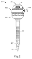
図1〜2は、低侵襲性手術の実施のためのアクセスポートを提供するようにサイズ調整される例示的なトロカール器具(10)を示す。トロカール器具(10)は、栓子(20)、カニューレ(30)、及び封止アセンブリ(400)を含む。栓子(20)は、操作者が把持するための栓子握り部(24)、シャフト部(23)、及び栓子先端部(22)を含む。図2に示すように、栓子(20)は、封止アセンブリ(400)及びカニューレ(30)を通して挿入されるように構成されており、これにより、栓子先端部(22)は、栓子先端部(22)がカニューレ(35)の遠位端を過ぎて遠位に延在する状態で、封止アセンブリ(400)及びカニューレ(30)を通過し、これによって、栓子先端部(22)が患者の組織層を貫通又は切開して、手術部位に隣接して開口部を提供することを可能にする。シャフト部(23)は、組織の貫通及び切開中に組織層が及ぼす力に持ちこたえるように剛性である。栓子先端部(22)は、栓子(20)が手術部位に向かって組織層を通して挿入されるとき、組織層の貫通又は切開を容易にするのに十分な圧力を提供するように構成され、したがって、トロカール器具(10)が内部手術部位に向かって挿入されるとき、組織の開口部を広げるように形作られる。
I. Exemplary Trocar FIGS. 1-2 illustrate an exemplary trocar instrument (10) that is sized to provide an access port for performing minimally invasive surgery. Trocar instrument (10) includes an obturator (20), a cannula (30), and a sealing assembly (400). The obturator (20) includes an obturator grip (24), a shaft (23), and an obturator tip (22) for the operator to grasp. As shown in FIG. 2, the obturator (20) is configured to be inserted through the sealing assembly (400) and the cannula (30) so that the obturator tip (22) is inserted into the obturator. With the tip (22) extending distally past the distal end of the cannula (35), it passes through the sealing assembly (400) and cannula (30), thereby obturating the obturator tip (22). ) Can penetrate or cut through the patient's tissue layer to provide an opening adjacent to the surgical site. The shaft portion (23) is rigid to withstand the forces exerted by the tissue layer during tissue penetration and incision. The obturator tip (22) is configured to provide sufficient pressure to facilitate penetration or incision of the tissue layer when the obturator (20) is inserted through the tissue layer toward the surgical site. Thus, the trocar instrument (10) is shaped to widen the tissue opening when inserted toward the internal surgical site.
栓子(20)及びカニューレ(30)が、組織を通して挿入された後に、栓子(20)は、トロカール器具(10)の残部から除去されるが、一方カニューレ(30)は、組織内にそのまま残り、低侵襲性手術を実施するために、患者の体腔内に器具の挿入のための経路を提供する。カニューレ(30)は、封止アセンブリ(400)と連結するためのねじ切り(31)、封止アセンブリハウジング(34)、封止アセンブリハウジング(34)より遠位の中空シャフト(33)、中空シャフト(33)の外表面に沿う隆起部(35)、及び手術器具が手術部位にアクセスすることを可能にするように構成された開口先端部(32)を含む。栓子(20)が手術部位から除去されるとき、中空シャフト(33)は、手術部位に隣接する開口部を維持する。隆起部(35)は、患者の周辺組織層に追加の接触部を提供することによって、トロカール器具(10)に追加的な安定性をもたらすように構成されている。隆起部(35)は、加圧吹送流体(例えば、加圧空気など)が手術部位に導入されるときに安定性をもたらす上で特に有用であり、なぜなら、吹送流体がカニューレ(30)を手術部位から離れるように押し出す自然の傾向性を提供し得るからである。 After the obturator (20) and cannula (30) are inserted through the tissue, the obturator (20) is removed from the remainder of the trocar instrument (10) while the cannula (30) remains intact within the tissue. The remainder provides a path for instrument insertion into the patient's body cavity for performing minimally invasive surgery. The cannula (30) includes a threading (31) for coupling with the sealing assembly (400), a sealing assembly housing (34), a hollow shaft (33) distal to the sealing assembly housing (34), a hollow shaft ( 33) and a ridge (35) along the outer surface, and an open tip (32) configured to allow the surgical instrument to access the surgical site. When the obturator (20) is removed from the surgical site, the hollow shaft (33) maintains an opening adjacent to the surgical site. The ridge (35) is configured to provide additional stability to the trocar instrument (10) by providing additional contact to the patient's surrounding tissue layer. The ridge (35) is particularly useful in providing stability when a pressurized insufflation fluid (eg, pressurized air, etc.) is introduced into the surgical site, because the insufflation fluid surgically operates the cannula (30). This is because it can provide a natural tendency to push away from the site.
封止アセンブリ(400)は、栓子(20)又は手術器具がカニューレ(30)を介して手術部位に近づくことを可能にし、これと同時に加圧吹送流体が患者の体腔から漏出することを防止又は最小化することによって、患者の体腔のニューモスタシス(pneumostasis)を維持する。本実施例のトロカール器具(10)において、封止アセンブリ(400)は、カニューレ(30)と連結するためのねじ切り(425)、器具ポート(411)、及び弁(414)を含む。弁(414)は、操作者が、加圧吹送流体をトロカール器具(10)を通して患者の体腔内に選択的に導入又は放出することを可能にするように構成されている。 The sealing assembly (400) allows the obturator (20) or surgical instrument to approach the surgical site via the cannula (30) while simultaneously preventing pressurized insufflation fluid from leaking out of the patient's body cavity. Or, maintain pneumostasis of the patient's body cavity by minimizing. In the trocar instrument (10) of this example, the sealing assembly (400) includes a threading (425) for coupling with the cannula (30), an instrument port (411), and a valve (414). The valve (414) is configured to allow the operator to selectively introduce or release pressurized insufflation fluid through the trocar device (10) into the patient's body cavity.
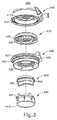
図3〜4は、封止アセンブリ(400)をより詳細に示す。図示するように、封止アセンブリ(400)は、頂部弁ハウジング(410)、接続リング(420)、器具封止部(430)、閉鎖弁基部(440)、及び閉鎖弁(450)を更に含む。頂部弁ハウジング(410)は、器具ポート(411)、吹送流体ポート(415)、及び弁(414)を含む。器具ポート(411)は、栓子(20)又は手術器具に手術部位へのアクセスを提供する。吹送流体ポート(415)は、頂部弁ハウジング(414)と流体連通し、これにより患者の吹送された体腔を提供するために、吹送流体は、頂部弁アセンブリ(414)、器具封止部(430)の周囲、及び閉鎖弁(450)の近位面を通過し、カニューレ(30)を通り、開口先端部(32)から出て、手術部位に至ることができる。 3-4 show the sealing assembly (400) in more detail. As shown, the sealing assembly (400) further includes a top valve housing (410), a connection ring (420), an instrument seal (430), a closure valve base (440), and a closure valve (450). . The top valve housing (410) includes an instrument port (411), an insufflation fluid port (415), and a valve (414). Instrument port (411) provides access to the surgical site for the obturator (20) or surgical instrument. The insufflation fluid port (415) is in fluid communication with the top valve housing (414), thereby providing insufflation fluid for the patient to the top valve assembly (414), instrument seal (430). ) And through the proximal face of the closure valve (450), through the cannula (30) and out of the open tip (32) to the surgical site.
器具封止部(430)及び閉鎖弁(450)は、患者の吹送された体腔内のニューモスタシスを維持するように協働する封止機構を形成する。この実施例では、閉鎖弁(450)は、「ダックビル」弁である。しかしながら、他のタイプの閉鎖弁、例えば、フラッパー弁なども使用されてもよい。内視鏡器具が、閉鎖弁(450)を通過すると、閉鎖弁(450)は開放するであろうが、通常は、器具に対して完全な封止を提供しない。内視鏡器具が、トロカール器具(10)から除去されるとき、閉鎖弁(450)は閉鎖され、吹送流体がトロカール器具(10)から漏出することを実質的に防止する。栓子(20)又は内視鏡手術器具が封止アセンブリ(400)を通して挿入されるときに閉鎖弁(450)を補うために、器具封止部(430)は、挿入された栓子(20)又は内視鏡手術器具に対して封止し、吹送流体がトロカール器具(10)を通って漏出することを防止する。しかしながら、器具封止部(430)は、通常、栓子(20)又は内視鏡器具がトロカール器具(10)に位置付けられない限り、単独でニューモスタシスを維持することはないであろう。したがって、器具封止部(430)及び閉鎖弁(450)は一緒に、栓子(20)又は内視鏡手術器具がトロカール器具(10)内に配設されるかどうかに無関係に、ニューモスタシスの状態を維持する。 Instrument seal (430) and closure valve (450) form a sealing mechanism that cooperates to maintain pneumostasis in the infused body cavity of the patient. In this example, the closure valve (450) is a “duck bill” valve. However, other types of closing valves, such as flapper valves, may also be used. When the endoscopic instrument passes through the closure valve (450), the closure valve (450) will open, but typically does not provide a perfect seal for the instrument. When the endoscopic instrument is removed from the trocar instrument (10), the closing valve (450) is closed, substantially preventing insufflation fluid from leaking out of the trocar instrument (10). To supplement the closure valve (450) when the obturator (20) or endoscopic surgical instrument is inserted through the sealing assembly (400), the instrument seal (430) is inserted into the inserted obturator (20). ) Or endoscopic surgical instrument to prevent insufflation fluid from leaking through the trocar instrument (10). However, the instrument seal (430) will typically not maintain pneumostasis alone unless the obturator (20) or endoscopic instrument is positioned on the trocar instrument (10). Thus, the instrument seal (430) and the shut-off valve (450) together, regardless of whether an obturator (20) or endoscopic surgical instrument is disposed within the trocar instrument (10) Maintain the state.
接続リング(420)は、器具封止部(430)及び閉鎖弁(450)に封止表面も提供しつつ、同時に封止アセンブリ(400)をカニューレ(30)と接続する。接続リング(420)は、カニューレ(30)のねじ切り(31)と対応する外側ねじ切り(425)を有する。接続リング(420)はまた、閉鎖弁基部(440)上に存在する複数の柱状物(442)と対応する複数のインサート(428)をその遠位側に有する。これは、接続リング(420)及び閉鎖弁基部(440)が閉鎖弁(450)の周囲の周りで封止を効果的に提供することを可能にする。同様に、頂部弁ハウジング(410)及び接続リング(420)もまた、中に挟まれた器具封止部(430)と一体となって、器具封止部(430)の周囲の周りに封止を提供する。 The connection ring (420) also provides a sealing surface for the instrument seal (430) and the closure valve (450) while simultaneously connecting the seal assembly (400) with the cannula (30). The connection ring (420) has an outer threading (425) corresponding to the threading (31) of the cannula (30). The connection ring (420) also has a plurality of inserts (428) on its distal side corresponding to the plurality of pillars (442) present on the closure valve base (440). This allows the connection ring (420) and the closure valve base (440) to effectively provide a seal around the perimeter of the closure valve (450). Similarly, the top valve housing (410) and connecting ring (420) are also sealed around the periphery of the instrument seal (430), united with the instrument seal (430) sandwiched therein. I will provide a.
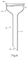
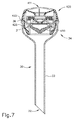
患者の吹送された体腔内のニューモスタシスを維持するために、図6に示すカニューレ(36)の近位唇部と、封止アセンブリ(400)のいくつかの遠位表面(422、443)との間の接点は、封止を効果的に創出し得る。図7は、対応するねじ切り(425、31)を介して封止アセンブリ(400)と連結されたカニューレ(30)を示す。対応するねじ切り(425、31)は、封止アセンブリ(400)の遠位表面(422)とカニューレ(36)の近位唇部と間に封止を創出するのに十分な力を提供するために、カニューレ(30)の内部に沿って十分な程の所まで延びる。この封止を更に容易にするために、Oリング(図示せず)などのエラストマー材が、カニューレ(36)の唇部と封止アセンブリ(500)の遠位表面(510)との間で使用されてもよい。 To maintain pneumostasis within the infused body cavity of the patient, the proximal lip of the cannula (36) shown in FIG. 6 and several distal surfaces (422, 443) of the sealing assembly (400) The contacts between can effectively create a seal. FIG. 7 shows the cannula (30) connected to the sealing assembly (400) via corresponding threading (425, 31). The corresponding threading (425, 31) provides sufficient force to create a seal between the distal surface (422) of the seal assembly (400) and the proximal lip of the cannula (36). And extend to a sufficient extent along the interior of the cannula (30). To further facilitate this sealing, an elastomeric material such as an O-ring (not shown) is used between the lip of the cannula (36) and the distal surface (510) of the sealing assembly (500). May be.
前述のものに加えて又はその代わりに、トロカールアセンブリ(10)の種々の構成要素及び特徴が、下記の特許文献の教示の少なくとも一部に従って構築され、かつ動作可能であってもよい。米国特許第5,385,553号、米国特許第5,628,732号、米国特許第5,709,671号、米国特許第5,385,572号、米国特許第5,609,604号、米国特許第5,697,913号、米国特許第5,817,061号、米国特許第5,449,370号、米国特許第8,221,364号、及び/又は米国特許第8,728,037号。これらの特許のそれぞれの開示内容は、参照により本明細書に組み込まれる。 In addition to or instead of the foregoing, various components and features of the trocar assembly (10) may be constructed and operable in accordance with at least some of the teachings of the following patent documents. U.S. Patent No. 5,385,553, U.S. Patent No. 5,628,732, U.S. Patent No. 5,709,671, U.S. Patent No. 5,385,572, U.S. Patent No. 5,609,604, US Patent No. 5,697,913, US Patent No. 5,817,061, US Patent No. 5,449,370, US Patent No. 8,221,364, and / or US Patent No. 8,728, 037. The disclosure of each of these patents is incorporated herein by reference.
II.例示的なロボットカニューレ
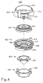
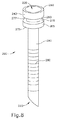
図8〜図9は、別の例示的なカニューレ(200)を示す。本実施例のカニューレ(200)は、米国特許第6,364,888号、米国特許第7,524,320号、及び米国特許第7,806,891号に記載されるロボット手術システムなどのロボット手術システムで使用するように構成されている。これらの特許のそれぞれの開示内容は、参照により本明細書に組み込まれる。ほんの一例として、カニューレ(200)は、以下の特許文献の教示の少なくとも一部に従って構築され、動作可能であってもよい。その開示内容が参照により本明細書に組み込まれる、2012年3月29日に公開された「Cannula」と題する米国公開第2012/0078245号。上述したカニューレ(30)と同様に、本実施例のカニューレ(200)は、中空シャフト(290)に至る近位の角度をなした開口部(230)、隆起部(280)、及び手術器具が手術部位にアクセスすることを可能にする開口先端部(220)を有する。中空シャフト(290)は、長手方向軸を画定する。しかしながら、カニューレ(200)は、これが封止アセンブリ(400)を支持するように構成された封止アセンブリハウジング(34)を有しないために、上述したカニューレ(30)とは異なる。カニューレ(200)の近位端で封止アセンブリハウジング(34)を有する代わりに、カニューレ取付けブラケット顎部(図示せず)と嵌合するように構成されている、2つの隆起した環状フランジ(240、265)と取付け部分(260)とがある。環状フランジ(240、265)は、中空シャフト(290)によって画定された長手方向軸に対して実質的に垂直である唇部(250、277、270、275)を画定する。カニューレ取付けブラケット顎部(図示せず)は、カニューレ(200)をロボット手術システムのマニプレータアーム(図示せず)に固定するために、環状フランジ(240、265)及び取付け部分(260)の周辺の途中まで達する。
II. Exemplary Robot Cannula FIGS. 8-9 illustrate another exemplary cannula (200). The cannula (200) of this example is a robot such as the robotic surgical system described in US Pat. No. 6,364,888, US Pat. No. 7,524,320, and US Pat. No. 7,806,891. Configured for use in a surgical system. The disclosure of each of these patents is incorporated herein by reference. By way of example only, cannula (200) may be constructed and operable in accordance with at least some of the teachings of the following patent documents. US Publication No. 2012/0078245 entitled “Cannula” published March 29, 2012, the disclosure of which is incorporated herein by reference. Similar to the cannula (30) described above, the cannula (200) of this example includes a proximal angled opening (230), ridge (280), and surgical instrument leading to the hollow shaft (290). It has an open tip (220) that allows access to the surgical site. The hollow shaft (290) defines a longitudinal axis. However, the cannula (200) differs from the cannula (30) described above because it does not have a seal assembly housing (34) configured to support the seal assembly (400). Instead of having a sealing assembly housing (34) at the proximal end of the cannula (200), two raised annular flanges (240) configured to mate with a cannula mounting bracket jaw (not shown). 265) and an attachment portion (260). The annular flange (240, 265) defines a lip (250, 277, 270, 275) that is substantially perpendicular to the longitudinal axis defined by the hollow shaft (290). A cannula mounting bracket jaw (not shown) is provided around the annular flange (240, 265) and mounting portion (260) to secure the cannula (200) to the manipulator arm (not shown) of the robotic surgical system. It reaches halfway.
カニューレ(200)は、ロボット操作を提供するために、封止アセンブリハウジング(34)の代わりに環状フランジ(240、265)及び取付け部分(260)を含むので、封止アセンブリ(400)は、カニューレ(200)と直接対応しない場合がある。図7に示すように、前の実施例のカニューレ(30)は、封止アセンブリ(500)を支持するための封止アセンブリハウジング(34)、並びに封止アセンブリ(500)の遠位表面(510)と嵌合するように構成された対応するねじ切り(31)及び近位唇部(36)を有する。これらの特徴の全ては、ニューモスタシスを維持するために、封止アセンブリとカニューレとの間の封止接続を提供する助けとなる。これとは対照的に、図10は、本実施例のカニューレ(200)の上に位置付けられた例示的な封止アセンブリ(400)を示す。カニューレ(200)は、封止アセンブリ(400)の少なくとも1つの遠位表面(443)と接触することができる唇部(250)を有するが、カニューレ(200)は、封止アセンブリ(400)に支持をもたらすための対応するハウジングと、ニューモスタシスを維持するために十分な封止接続を創出するのに十分な力を提供するための手段とを欠如している。したがって、封止アセンブリ(500)とカニューレ(200)との間に適切な連結を提供するために、いくつかの追加の構成要素が必要となる。そのような構成要素の実施例が、以下でより詳しく述べられる。 Since the cannula (200) includes an annular flange (240, 265) and a mounting portion (260) instead of the seal assembly housing (34) to provide robotic operation, the seal assembly (400) is a cannula. (200) may not correspond directly. As shown in FIG. 7, the cannula (30) of the previous example includes a seal assembly housing (34) for supporting the seal assembly (500), as well as a distal surface (510) of the seal assembly (500). ) With corresponding threading (31) and proximal lip (36). All of these features help provide a sealing connection between the sealing assembly and the cannula to maintain pneumostasis. In contrast, FIG. 10 shows an exemplary sealing assembly (400) positioned over the cannula (200) of this example. The cannula (200) has a lip (250) that can contact at least one distal surface (443) of the sealing assembly (400), but the cannula (200) is attached to the sealing assembly (400). It lacks a corresponding housing for providing support and means for providing sufficient force to create a sufficient sealing connection to maintain pneumostasis. Thus, several additional components are required to provide a proper connection between the sealing assembly (500) and the cannula (200). Examples of such components are described in more detail below.
III.封止アセンブリ及びロボットカニューレのための例示的なアダプター
図11〜12は、患者の吹送された体腔内のニューモスタシスを維持しつつ、カニューレ(200)を封止アセンブリ(400)と接続するためのアダプター(300)を示す。アダプター(300)は、ハウジング床(370)、ハウジング傾斜面(390)、及びハウジング壁(395)によって画定された封止アセンブリハウジング(385)を含む。アダプタ(300)は、レーデル(Radel)などの硬質プラスチックから構成されており、封止アセンブリ(400)のねじ切り(425)と対応するねじ切り(360)を有する。当然ながら、多くの種類の硬質プラスチック材が使用されてもよく、当業者には明らかであるだろう。可能な硬質プラスチックのいくつかの例としては、SustaPEEK MG、Susta PEI MG、及びポリスルホンが挙げられるが、これらに限定されない。この対応するねじ切り(360、425)は、アダプター(300)の近位端(310)及び封止アセンブリ(400)の遠位表面(422)が一緒に連結し、ニューモスタシスを維持するために効果的な封止を創出することを可能にする。しかしながら、アダプター(300)は、封止アセンブリ(500)のねじ切り(530)とアダプター(300)のハウジング壁(395)との間に干渉を創出するように構成された寸法を有するエラストマー材で全体的に作製され、ニューモスタシスを維持するための封止を創出することも可能である。したがって、ねじ切り(360)は、アダプター(300)に必ずしも必要であるというわけではない。エラストマー材は、硬質プラスチックに加えて又は硬質プラスチックの代わりに使用されてもよい。アダプター(300)のいくつかの変形例において、Oリング(図示せず)などのエラストマー構成要素は、アダプター(300)の近位端(310)と封止アセンブリ(400)の遠位表面(422)との間に位置付けられ、近位端(310)と遠位表面(422)との間の封止を提供又は向上させて、ニューモスタシスを更に維持する。
III. Exemplary Adapter for Sealing Assembly and Robot Cannula FIGS. 11-12 are for connecting the cannula (200) with the sealing assembly (400) while maintaining pneumostasis within the insufflated body cavity of the patient. The adapter (300) is shown. The adapter (300) includes a sealing assembly housing (385) defined by a housing floor (370), a housing ramp (390), and a housing wall (395). The adapter (300) is constructed from a hard plastic such as Radel and has a threading (360) corresponding to the threading (425) of the sealing assembly (400). Of course, many types of hard plastic materials may be used and will be apparent to those skilled in the art. Some examples of possible rigid plastics include, but are not limited to, SustaPEEK MG, Susta PEI MG, and polysulfone. This corresponding threading (360, 425) is effective to connect the proximal end (310) of the adapter (300) and the distal surface (422) of the sealing assembly (400) together to maintain pneumostasis. It is possible to create a static seal. However, the adapter (300) is generally an elastomeric material having dimensions configured to create interference between the threading (530) of the sealing assembly (500) and the housing wall (395) of the adapter (300). It is also possible to create a seal to be created and maintain pneumostasis. Thus, threading (360) is not necessarily required for adapter (300). The elastomeric material may be used in addition to or instead of hard plastic. In some variations of the adapter (300), an elastomeric component, such as an O-ring (not shown), is attached to the proximal end (310) of the adapter (300) and the distal surface (422) of the sealing assembly (400). ) To provide or enhance a seal between the proximal end (310) and the distal surface (422) to further maintain pneumostasis.
アダプター(300)は、チャネル表面(320)によって画定されたチャネル(325)を更に含む。チャネル(325)は、栓子(20)又は手術器具が、アダプター(300)を介して封止アセンブリ(400)からカニューレ(200)まで通っていくことを可能にし、これによって手術部位にアクセスする。チャネル(325)は、封止アセンブリ(500)とカニューレ(200)との間の流体連通のための経路を更に提供する。 The adapter (300) further includes a channel (325) defined by the channel surface (320). Channel (325) allows obturator (20) or surgical instrument to pass from sealing assembly (400) to cannula (200) via adapter (300), thereby accessing the surgical site. . Channel (325) further provides a path for fluid communication between sealing assembly (500) and cannula (200).
アダプタ(300)はまた、2つの環状壁、外側テーパ部(340)、及び内側テーパ部(330)も有し、両方のテーパ部(330、340)は、ハウジング床(370)の下に位置する。外側テーパ部(340)は、フランジ(240)の外径よりも小さい内径を有し得る。いくつかの変形例において、内側テーパ部(330)の遠位端は、近位の角度をなした開口部(230)の内径よりも小さい外径を有し得るが、一方、内側テーパ部(330)の近位端は、近位の角度をなした開口部(230)の内径よりも大きな外径を有し得る。換言すれば、内側テーパ部(330)は、近位の角度をなした開口部(230)のテーパ角度よりも広い角度でテーパ形状になってもよい。これは、向上した締まりばめを提供し得る。外側テーパ部(340)及び内側テーパ部(330)は一緒になって、トロカールルーフ(350)で終端する。内側テーパ部(330)は、カニューレ(200)の近位の角度をなした開口部(230)の中に収まるように周径でサイズ調整されており近位の角度をなした開口部(230)を画定する内壁のものと同様な角度でテーパ形状となる。外側テーパ部(340)は、フランジ(240)の周径を補完するように周径でサイズ調整されており、深さはフランジ(240)の深さを超えない。外側テーパ部(340)及び内側テーパ部(330)のために、トロカールルーフ(350)は、カニューレ(200)の唇部(250)を補完する。 The adapter (300) also has two annular walls, an outer taper (340) and an inner taper (330), both tapers (330, 340) being located under the housing floor (370). To do. The outer taper (340) may have an inner diameter that is smaller than the outer diameter of the flange (240). In some variations, the distal end of the inner taper (330) may have an outer diameter that is smaller than the inner diameter of the proximal angled opening (230), while the inner taper ( The proximal end of 330) may have an outer diameter that is greater than the inner diameter of the proximal angled opening (230). In other words, the inner taper portion (330) may be tapered at a wider angle than the taper angle of the proximal angled opening (230). This can provide an improved interference fit. The outer taper (340) and the inner taper (330) together terminate in a trocar roof (350). The inner taper (330) is sized around the circumference to fit within the proximal angled opening (230) of the cannula (200) and has a proximal angled opening (230). ) In a tapered shape at an angle similar to that of the inner wall. The outer taper part (340) is sized by the circumference so as to complement the circumference of the flange (240), and the depth does not exceed the depth of the flange (240). Due to the outer taper (340) and the inner taper (330), the trocar roof (350) complements the lip (250) of the cannula (200).
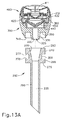
図13Aは、封止アセンブリ(400)に接続されたアダプター(300)を示す。アダプター(300)のねじ切り(360は、封止アセンブリ(400)のねじ切り(425)に接続する。ねじ切り(425、360)のこの係合を通して、封止アセンブリ(400)の遠位表面(422)とアダプター(300)の近位端(310)との間の接続は、患者の吹送された体腔内のニューモスタシスの維持をもたらすのに十分なものとなる。また、封止アセンブリハウジング(385)は、封止アセンブリ(400)を支持し、これにより、アダプター(300)が安定であるならば、封止アセンブリ(400)も安定である。 FIG. 13A shows the adapter (300) connected to the sealing assembly (400). The threading (360) of the adapter (300) connects to the threading (425) of the sealing assembly (400). Through this engagement of the threading (425, 360), the distal surface (422) of the sealing assembly (400). And the proximal end (310) of the adapter (300) will be sufficient to provide maintenance of pneumostasis within the insufflated body cavity of the patient, and the sealing assembly housing (385). Supports the sealing assembly (400) so that if the adapter (300) is stable, the sealing assembly (400) is also stable.
図13Bは、カニューレ(200)と相互作用するアダプター(300)の補完的な配置を示す。ニューモスタシスを維持するアダプター(300)とフランジ(240)との間の封止は、複数の材料を用いて創出することができる。アダプター(300)がエラストマー材から全体的に作製される場合、内側テーパ部(330)は、近位の角度をなした開口部(230)を画定する内壁と干渉するような寸法にすることができ、外側テーパ部(340)は、フランジ(240)と干渉するような寸法にすることができるか、又は内側テーパ部(330)及び外側テーパ部(340)の両方を、それぞれ近位の角度をなした開口部(230)及びフランジ(240)を画定する内壁と干渉するような寸法にすることができる。これらの可能性の全ては、実際に患者の吹送された体腔内でニューモスタシスを維持する封止を創出することができる。 FIG. 13B shows a complementary arrangement of the adapter (300) that interacts with the cannula (200). The seal between adapter (300) and flange (240) that maintains pneumostasis can be created using multiple materials. When the adapter (300) is made entirely from an elastomeric material, the inner taper (330) may be dimensioned to interfere with the inner wall defining the proximal angled opening (230). The outer taper (340) can be dimensioned to interfere with the flange (240), or both the inner taper (330) and the outer taper (340) are each at a proximal angle. And can be dimensioned to interfere with the inner wall defining the defined opening (230) and flange (240). All of these possibilities can actually create a seal that maintains pneumostasis within the infused body cavity of the patient.
アダプター(300)は、剛体から部分的に作製され得る。その場合、内側テーパ部(330)の周りにオーバーモールドされたエラストマー材が存在することが可能であり、このオーバーモールドは、近位の角度をなした開口部(230)を画定する内壁に干渉するような寸法にされる。外側テーパ部(340)の周りにオーバーモールドされたエラストマー材が存在することが可能であり、このオーバーモールドは、フランジ(240)と干渉するような寸法にされる。内側テーパ部(330)及び外側テーパ部(340)の両方の周りにオーバーモールドされたエラストマー材が存在することも可能であり、このオーバーモールドは、それぞれ近位の角度をなした開口部(230)及びフランジ(240)を画定する内壁と干渉するような寸法にされる。この場合もやはり、これらの可能性の全ては、実際に患者の吹送された体腔内でニューモスタシスを維持する封止を創出することが可能である。 The adapter (300) can be made in part from a rigid body. In that case, there can be an overmolded elastomeric material around the inner taper (330) that interferes with the inner wall defining the proximal angled opening (230). The dimensions are as follows. There can be an overmolded elastomeric material around the outer taper (340), which is dimensioned to interfere with the flange (240). It is also possible that there is an overmolded elastomeric material around both the inner taper (330) and the outer taper (340), each of which has a proximal angled opening (230). ) And the inner wall defining the flange (240). Again, all of these possibilities can actually create a seal that maintains pneumostasis within the patient's insufflated body cavity.
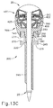
アダプター(300)は、全体的に剛体から作製されることも可能であり、エラストマーOリングを、カニューレ(200)とアダプター(300)との接点のいずれかの間に付加することが可能である。例えば、エラストマーOリングは、内側テーパ部(330)と近位の角度をなした開口部(230)を画定する内壁との間に付加することが可能である。あるいは、エラストマーOリングは、外側テーパ部(340)とフランジ(240)との間にあることが可能である。更に、エラストマーOリングは、トロカールルーフ(350)とカニューレ(200)の唇部(250)との間にあることが可能である。これらの可能性又はその組み合わせの全ては、アダプター(300)とカニューレ(200)との間に封止を創出することが可能である。カニューレ(200)が、ねじ切り(図示せず)を有する場合、ニューモスタシスを維持するために必要な力を創出するために、アダプター(300)は、補完的なねじ切り(図示せず)を有するように変更することができる。しかしながら、当業者であれば、限定されないが、ラッチ及びスナップ嵌め特徴部などの、ニューモスタシスを維持するために必要な力を創出する他の方法を認識するであろう。図13Cは、アダプター(300)が、患者の吹送された体腔内のニューモスタシスを維持する能力を有しつつ、栓子(20)の封止アセンブリ(400)、アダプター(300)、及びカニューレ(200)を通しての挿入のため経路をどのように提供するかを示す。 The adapter (300) can also be made entirely rigid, and an elastomeric O-ring can be added between any of the cannula (200) and adapter (300) contacts. . For example, an elastomeric O-ring can be added between the inner taper (330) and the inner wall defining the proximal angled opening (230). Alternatively, the elastomeric O-ring can be between the outer taper (340) and the flange (240). Further, the elastomeric O-ring can be between the trocar roof (350) and the lip (250) of the cannula (200). All of these possibilities or combinations thereof can create a seal between adapter (300) and cannula (200). If the cannula (200) has threading (not shown), the adapter (300) will have complementary threading (not shown) to create the force necessary to maintain pneumostasis. Can be changed. However, those skilled in the art will recognize other ways of creating the force necessary to maintain pneumostasis, such as, but not limited to, latches and snap-fit features. FIG. 13C shows that the seal assembly (400) of the obturator (20), the adapter (300), and the cannula (300) while the adapter (300) has the ability to maintain pneumostasis in the patient's infused body cavity 200) how the path is provided for insertion through.
IV.その他
本明細書に記載の教示、表現、実施形態、実施例などのうちのいずれか1つ又は2つ以上を、本明細書に記載の他の教示、表現、実施形態、実施例などのうちのいずれか1つ又は2つ以上と組み合わせることができる点が理解されるべきである。したがって、上記の教示、表現、実施形態、実施例などは、互いに対して独立して考慮されるべきではない。本明細書の教示に照らして、本明細書の教示を組み合わせることができる種々の好適な方法が、当業者には容易に明らかとなろう。かかる改変例及び変形例は、特許請求の範囲内に含まれることを意図される。
IV. Others Any one or more of the teachings, expressions, embodiments, examples and the like described in the present specification may be combined with other teachings, expressions, embodiments, examples, and the like described in the specification. It should be understood that any one or more of can be combined. Accordingly, the above teachings, expressions, embodiments, examples and the like should not be considered independently of one another. Various suitable ways in which the teachings herein can be combined will be readily apparent to those skilled in the art in light of the teachings herein. Such modifications and variations are intended to be included within the scope of the claims.
本明細書に参照により組み込まれるといわれるいかなる特許、刊行物、又は他の開示文献も、全体的に又は部分的に、組み込まれた内容が現行の定義、見解、又は本開示に記載された他の開示内容とあくまで矛盾しない範囲でのみ本明細書に組み込まれることが理解されるべきである。それ自体、また必要な範囲で、本明細書に明示的に記載される開示内容は、参照により本明細書に組み込まれるあらゆる矛盾する記載に優先するものとする。参照により本明細書に組み込まれるものとするが、既存の定義、記載、又は本明細書に記載される他の開示文献と矛盾する任意の文献、又はそれらの部分は、組み込まれた文献と既存の開示文献との間に矛盾が生じない範囲においてのみ組み込まれるものとする。 Any patent, publication, or other disclosure document referred to herein by reference may, in whole or in part, be incorporated into the current definition, opinion, or other disclosure in this disclosure. It is to be understood that the present disclosure is incorporated only to the extent that it does not contradict the disclosure content of. As such and to the extent necessary, the disclosure expressly set forth herein shall supersede any conflicting description incorporated herein by reference. Any reference, or part thereof, that is incorporated herein by reference, but that conflicts with existing definitions, descriptions, or other disclosed references contained herein, is incorporated herein by reference. It shall be incorporated only to the extent that no contradiction arises with the disclosed document.
上述の変形例は、1回の使用後に廃棄されるように設計されてもよく、あるいは、それらは、複数回使用されるように設計されてもよい。いずれか又は両方の場合において、変形例は、少なくとも1回の使用後に再利用のために再調整され得る。再調整は、装置の分解工程、それに続く特定の部品の洗浄又は交換工程、及びその後の再組立て工程の任意の組み合わせを含み得る。特に、装置のいくつかの形態は分解することができ、また、装置の任意の数の特定の部材又は部品を、任意の組み合わせで選択的に交換又は除去してもよい。特定の部品の洗浄及び/又は交換に際して、装置の特定の形態を、再調整用の施設において、又は手術の直前に使用者により再組み立てして、その後の使用に供することができる。当業者であれば、装置の再調整において、分解、洗浄/交換、及び再組み立てのための様々な技術を使用できる点は認識するであろう。かかる技術の使用、及び結果として得られる再調整された装置は、全て本出願の範囲内にある。 The variants described above may be designed to be discarded after a single use, or they may be designed to be used multiple times. In either or both cases, the variant may be reconditioned for reuse after at least one use. Reconditioning can include any combination of equipment disassembly steps, followed by cleaning or replacement of specific parts, and subsequent reassembly steps. In particular, some forms of the device can be disassembled, and any number of the particular members or parts of the device may be selectively replaced or removed in any combination. Upon cleaning and / or replacement of certain parts, certain forms of the device can be reassembled by the user at a reconditioning facility or immediately prior to surgery for subsequent use. One skilled in the art will recognize that various techniques for disassembly, cleaning / replacement, and reassembly can be used in reconditioning the device. The use of such techniques and the resulting reconditioned device are all within the scope of this application.
ほんの一例として、本明細書に記載されるバージョンは、手術の前及び/又は後に滅菌されてもよい。1つの滅菌法では、装置をプラスチック製又はTYVEK製のバックなどの閉鎖かつ密封された容器に入れる。次いで、容器及び装置を、γ線、X線、又は高エネルギー電子線などの、容器を透過する放射線場に置くことができる。放射線は、装置の表面及び容器内の細菌を死滅させることができる。この後、滅菌された装置を、後の使用のために、滅菌容器中で保管することができる。装置は、また、β線若しくはγ線、エチレンオキシド、又は水蒸気が挙げられるが、これらに限定されない、当該技術分野で既知の任意の別の技術を用いて滅菌され得る。 By way of example only, the versions described herein may be sterilized before and / or after surgery. In one sterilization method, the device is placed in a closed and sealed container, such as a plastic or TYVEK bag. The container and device can then be placed in a radiation field that penetrates the container, such as gamma rays, x-rays, or high energy electron beams. Radiation can kill bacteria on the surface of the device and in the container. After this, the sterilized device can be stored in a sterile container for later use. The device can also be sterilized using any other technique known in the art including, but not limited to, beta or gamma radiation, ethylene oxide, or water vapor.
以上、本発明の種々の実施形態を図示及び説明したが、本発明の範囲から逸脱することなく、当業者による適切な改変により、本明細書に記載される方法及びシステムの更なる適合化を実現することができる。そのような可能な改変のうちのいくつかについて述べたが、他の改変も当業者には明らかになるであろう。例えば、上記で論じた実施例、実施形態、形状、材料、寸法、比率、工程などは例示的なものであって必須のものではない。したがって、本発明の範囲は、以下の特許請求の範囲の観点から考慮されるべきものであり、本明細書及び図面において図示され、説明された構造及び動作の細部に限定されないものとして理解される。 While various embodiments of the invention have been illustrated and described, further adaptations of the methods and systems described herein can be made by appropriate modifications by those skilled in the art without departing from the scope of the invention. Can be realized. Although some of such possible modifications have been described, other modifications will be apparent to those skilled in the art. For example, the examples, embodiments, shapes, materials, dimensions, ratios, processes, etc. discussed above are exemplary and not essential. Accordingly, the scope of the present invention should be considered in terms of the following claims and is understood not to be limited to the details of construction and operation shown and described in the present specification and drawings. .
〔実施の態様〕
(1) (a)封止アセンブリハウジングであって、封止アセンブリハウジングが、近位端と遠位端とを備える、封止アセンブリハウジングと、
(b)チャネルであって、前記チャネルが、長手方向軸を画定し、前記チャネルが、近位端と遠位端とを備え、前記チャネルの前記近位端が、前記封止アセンブリハウジングの前記遠位端と流体連通する、チャネルと、
(c)前記チャネルの少なくとも前記遠位端を包囲する内側テーパ形状表面であって、前記内側テーパ形状表面が、近位端と遠位端とを備え、前記近位端が、前記遠位端よりも大きな周囲を有する、内側テーパ形状表面と、
(d)外側テーパ形状表面であって、前記外側テーパ形状表面が、近位端と遠位端とを備える、外側テーパ形状表面と、
(e)トロカールルーフであって、前記トロカールルーフが、前記内側テーパ形状表面及び前記外側テーパ形状表面の近位端の終端の間で画定されている、トロカールルーフと、を備える、装置。
(2) 前記装置が、エラストマー材で全体的に形成されている、実施態様1に記載の装置。
(3) 前記装置が、中空カニューレを更に備え、前記カニューレが、近位の角度をなした開口部を有する環状フランジを備え、前記内側テーパ形状表面が、前記カニューレの前記近位の角度をなした開口部と締まりばめを提供するように構成されている、実施態様2に記載の装置。
(4) 前記外側テーパ形状表面が、前記カニューレの前記環状フランジの外周と干渉するように構成されている、実施態様3に記載の装置。
(5) 前記装置が、中空カニューレを更に備え、前記カニューレが、環状フランジを備え、前記外側テーパ形状表面が、前記カニューレの前記環状フランジの外周と締まりばめを提供するように構成されている、実施態様2に記載の装置。
Embodiment
(1) (a) a sealing assembly housing, wherein the sealing assembly housing comprises a proximal end and a distal end;
(B) a channel, wherein the channel defines a longitudinal axis, the channel comprising a proximal end and a distal end, wherein the proximal end of the channel is the portion of the sealing assembly housing; A channel in fluid communication with the distal end;
(C) an inner tapered surface surrounding at least the distal end of the channel, the inner tapered surface comprising a proximal end and a distal end, the proximal end being the distal end An inner tapered surface having a larger perimeter, and
(D) an outer tapered surface, wherein the outer tapered surface comprises a proximal end and a distal end;
(E) a trocar roof, the trocar roof comprising a trocar roof defined between a distal end of a proximal end of the inner tapered surface and the outer tapered surface.
(2) The apparatus according to embodiment 1, wherein the apparatus is entirely formed of an elastomer material.
(3) The device further comprises a hollow cannula, the cannula comprises an annular flange having a proximal angled opening, and the inner tapered surface forms the proximal angle of the cannula. The apparatus of embodiment 2, wherein the apparatus is configured to provide a closed opening and an interference fit.
4. The apparatus of
(5) The apparatus further comprises a hollow cannula, the cannula comprises an annular flange, and the outer tapered surface is configured to provide an interference fit with the outer periphery of the annular flange of the cannula.
(6) 前記装置が、硬質材料で部分的に形成され、エラストマー材で部分的に形成されている、実施態様1に記載の装置。
(7) 前記装置が、ねじ切りを有する封止アセンブリを更に備え、前記封止アセンブリハウジングが、前記封止アセンブリの前記ねじ切りを補完するように構成されたねじ切りを更に備える、実施態様1に記載の装置。
(8) 前記装置が、中空カニューレを更に備え、前記カニューレが、近位の角度をなした開口部を有する環状フランジを備え、前記内側テーパ形状表面が、エラストマー材を備え、前記エラストマー材が、前記カニューレの前記近位の角度をなした開口部と締まりばめを提供するように構成されている、実施態様1に記載の装置。
(9) 前記装置が、中空カニューレを更に備え、前記カニューレが、近位の角度をなした開口部を有する環状フランジを備え、前記外側テーパ形状表面が、エラストマー材を備え、前記エラストマー材が、前記カニューレの前記環状フランジの前記外周と締まりばめを提供するように構成されている、実施態様1に記載の装置。
(10) 前記トロカールルーフの周りにオーバーモールドされたエラストマー材を更に備える、実施態様1に記載の装置。
(6) The apparatus according to embodiment 1, wherein the apparatus is partially formed of a hard material and partially formed of an elastomer material.
7. The apparatus of claim 1, wherein the apparatus further comprises a sealing assembly having threading, and the sealing assembly housing further comprises threading configured to complement the threading of the sealing assembly. apparatus.
(8) The device further comprises a hollow cannula, the cannula comprises an annular flange having a proximal angled opening, the inner tapered surface comprises an elastomeric material, and the elastomeric material comprises: The device of embodiment 1, wherein the device is configured to provide an interference fit with the proximal angled opening of the cannula.
(9) The device further comprises a hollow cannula, the cannula comprises an annular flange having a proximal angled opening, the outer tapered surface comprises an elastomeric material, and the elastomeric material comprises: The apparatus of embodiment 1, wherein the apparatus is configured to provide an interference fit with the outer periphery of the annular flange of the cannula.
The apparatus of claim 1, further comprising an elastomeric material overmolded around the trocar roof.
(11) 前記外側テーパ形状表面の周りにオーバーモールドされたエラストマー材を更に備え、前記装置が、中空カニューレを更に備え、前記カニューレが、環状フランジを備え、前記エラストマー材が、前記カニューレの前記環状フランジの前記外周と干渉するように構成されている、実施態様1に記載の装置。
(12) 前記トロカールルーフの前記表面を補完するように構成されたOリングを更に備える、実施態様1に記載の装置。
(13) 前記装置が、中空カニューレを更に備え、前記カニューレが、近位の角度をなした開口部を有する環状フランジを備え、前記カニューレの前記近位の角度をなした開口部が、ねじ切りを備え、前記内側テーパ形状表面が、前記カニューレの前記近位の角度をなした開口部のねじ切りを補完するように構成されたねじ切りを更に備える、実施態様1に記載の装置。
(14) 前記装置が、中空カニューレを更に備え、前記カニューレが、環状フランジを備え、前記環状フランジの前記外周が、ねじ切りを備え、前記外側テーパ形状表面が、前記カニューレの前記環状フランジの前記外周上のねじ切りを補完するように構成されたねじ切りを更に備える、実施態様1に記載の装置。
(15) 前記装置が、硬質材料から全体的に形成されている、実施態様1に記載の装置。
(11) further comprising an elastomeric material overmolded around the outer tapered surface, wherein the device further comprises a hollow cannula, the cannula comprises an annular flange, and the elastomeric material comprises the annular of the cannula. 2. The apparatus of embodiment 1, configured to interfere with the outer periphery of the flange.
The apparatus of claim 1, further comprising an O-ring configured to complement the surface of the trocar roof.
(13) The device further comprises a hollow cannula, the cannula comprising an annular flange having a proximal angled opening, and the proximal angled opening of the cannula is threaded. The apparatus of claim 1, further comprising: the inner tapered surface further comprising a threading configured to complement threading of the proximal angled opening of the cannula.
(14) The device further comprises a hollow cannula, the cannula comprises an annular flange, the outer circumference of the annular flange comprises a thread, and the outer tapered surface is the outer circumference of the annular flange of the cannula. The apparatus of embodiment 1, further comprising a threading configured to complement the upper threading.
15. The apparatus according to embodiment 1, wherein the apparatus is entirely formed from a hard material.
(16) 前記装置が、雄ねじ切りを有する封止アセンブリを更に備え、前記封止アセンブリハウジングが、前記封止アセンブリの前記雄ねじ切りを補完するように構成された雌ねじ切りを更に備え、これにより、前記封止アセンブリの少なくとも一部が、前記封止アセンブリハウジング内に螺合するように構成されている、実施態様1に記載の装置。
(17) 前記装置が、中空カニューレを更に備え、前記カニューレが、近位の角度をなした開口部を有する環状フランジを備え、前記カニューレの前記近位の角度をなした開口部が、雌ねじ切りを備え、前記内側テーパ形状表面が、前記カニューレの前記近位開口部の前記雌ねじ切りを補完するように構成された雄ねじ切りを更に備える、実施態様16に記載の装置。
(18) 前記装置が、中空カニューレを更に備え、前記カニューレが、環状フランジを備え、前記環状フランジの前記外周が、雄ねじ切りを備え、前記外側テーパ形状表面が、前記カニューレの前記環状フランジの前記外周の前記雄ねじ切りを補完するように構成された雌ねじ切りを更に備える、実施態様16に記載の装置。
(19) (a)カニューレであって、前記カニューレが、近位の角度をなした開口部を有する環状フランジを備える、カニューレと、
(b)封止アセンブリであって、前記封止アセンブリが、近位端と遠位端とを有する、封止アセンブリと、
(c)アダプターであって、
(i)チャネルであって、前記チャネルが、近位端と遠位端とを備え、前記チャネルの前記近位端が、前記封止アセンブリの前記遠位端と流体連通し、前記チャネルの前記遠位端が、前記カニューレの前記近位の角度をなした開口部と流体連通する、チャネルと、
(ii)前記封止アセンブリの一部を受け入れるように構成された封止アセンブリハウジングであって、封止アセンブリハウジングが、近位端と遠位端とを備え、前記近位端が、環状表面を備え、前記環状表面が、前記アダプターと前記封止アセンブリとの間に封止を提供するように構成されている、封止アセンブリハウジングと、
(iii)前記チャネルの少なくとも前記遠位端を包囲する内側テーパ形状表面であって、前記内側テーパ形状表面が、近位端と遠位端とを備え、前記近位端が、前記遠位端よりも大きな周囲を有し、前記内側テーパ形状表面が、前記カニューレの前記近位の角度をなした開口部に挿入されるように構成されている、内側テーパ形状表面と、
(iv)前記環状フランジの少なくとも前記近位端を包囲する外側テーパ形状表面と、を備えるアダプターと、を備える、装置。
(20) (a)カニューレであって、前記カニューレが、近位開口部の周りに延在する環状フランジを備え、前記近位開口部が、側壁によって画定されている、カニューレと、
(b)封止アセンブリであって、前記封止アセンブリが、手術器具を受け入れるように構成された通路を画定し、前記封止アセンブリが、前記通路内に配設された手術器具に対して封止するように構成された少なくとも1つの封止部材を更に備える、封止アセンブリと、
(c)前記カニューレを前記封止アセンブリに連結するように構成されたアダプターと、を備え、前記アダプターが、
(i)前記近位開口部に位置付けられた第1のカニューレ取付け特徴部であって、前記カニューレ取付け特徴部が、前記近位開口部を画定する前記側壁に対して封止するように構成され、前記カニューレ取付け特徴部が、前記封止アセンブリの前記封止通路から前記カニューレの前記近位開口部に至る、器具の挿入のための経路を提供するように更に構成されている、第1のカニューレ取付け特徴部と、
(ii)前記環状フランジの周りに位置付けられた第2のカニューレ取付け特徴部と、を備える、装置。
(16) The apparatus further comprises a sealing assembly having male threading, and the sealing assembly housing further comprises female threading configured to complement the male threading of the sealing assembly, thereby The apparatus of embodiment 1, wherein at least a portion of the sealing assembly is configured to threadably engage within the sealing assembly housing.
(17) The device further comprises a hollow cannula, the cannula comprising an annular flange having a proximal angled opening, and the proximal angled opening of the cannula is internally threaded. 17. The apparatus of embodiment 16, wherein the inner tapered surface further comprises a male threading configured to complement the female threading of the proximal opening of the cannula.
(18) The device further comprises a hollow cannula, the cannula comprises an annular flange, the outer periphery of the annular flange comprises an external threading, and the outer tapered surface is a portion of the annular flange of the cannula. The apparatus of embodiment 16, further comprising a female thread configured to complement the male threading of the outer periphery.
(19) (a) a cannula, wherein the cannula comprises an annular flange having a proximal angled opening;
(B) a sealing assembly, wherein the sealing assembly has a proximal end and a distal end;
(C) an adapter,
(I) a channel, the channel comprising a proximal end and a distal end, wherein the proximal end of the channel is in fluid communication with the distal end of the sealing assembly; A channel having a distal end in fluid communication with the proximal angled opening of the cannula;
(Ii) a sealing assembly housing configured to receive a portion of the sealing assembly, the sealing assembly housing comprising a proximal end and a distal end, the proximal end being an annular surface; A sealing assembly housing, wherein the annular surface is configured to provide a seal between the adapter and the sealing assembly;
(Iii) an inner tapered surface surrounding at least the distal end of the channel, the inner tapered surface comprising a proximal end and a distal end, the proximal end being the distal end An inner tapered surface, wherein the inner tapered surface is configured to be inserted into the proximal angled opening of the cannula;
(Iv) an adapter comprising an outer tapered surface surrounding at least the proximal end of the annular flange.
(20) (a) a cannula, wherein the cannula comprises an annular flange extending around a proximal opening, the proximal opening being defined by a sidewall;
(B) a sealing assembly, wherein the sealing assembly defines a passage configured to receive a surgical instrument, the sealing assembly sealing against a surgical instrument disposed in the passage. A sealing assembly further comprising at least one sealing member configured to stop;
(C) an adapter configured to couple the cannula to the sealing assembly, the adapter comprising:
(I) a first cannula attachment feature positioned in the proximal opening, wherein the cannula attachment feature is configured to seal against the sidewall defining the proximal opening; The cannula attachment feature is further configured to provide a path for insertion of an instrument from the sealing passage of the sealing assembly to the proximal opening of the cannula; A cannula attachment feature;
(Ii) a second cannula attachment feature positioned about the annular flange.
Claims (20)
(b)チャネルであって、前記チャネルが、長手方向軸を画定し、前記チャネルが、近位端と遠位端とを備え、前記チャネルの前記近位端が、前記封止アセンブリハウジングの前記遠位端と流体連通する、チャネルと、
(c)前記チャネルの少なくとも前記遠位端を包囲する内側テーパ形状表面であって、前記内側テーパ形状表面が、近位端と遠位端とを備え、前記近位端が、前記遠位端よりも大きな周囲を有する、内側テーパ形状表面と、
(d)外側テーパ形状表面であって、前記外側テーパ形状表面が、近位端と遠位端とを備える、外側テーパ形状表面と、
(e)トロカールルーフであって、前記トロカールルーフが、前記内側テーパ形状表面及び前記外側テーパ形状表面の近位端の終端の間で画定されている、トロカールルーフと、を備える、装置。 (A) a sealing assembly housing, the sealing assembly housing comprising a proximal end and a distal end;
(B) a channel, wherein the channel defines a longitudinal axis, the channel comprising a proximal end and a distal end, wherein the proximal end of the channel is the portion of the sealing assembly housing; A channel in fluid communication with the distal end;
(C) an inner tapered surface surrounding at least the distal end of the channel, the inner tapered surface comprising a proximal end and a distal end, the proximal end being the distal end An inner tapered surface having a larger perimeter, and
(D) an outer tapered surface, wherein the outer tapered surface comprises a proximal end and a distal end;
(E) a trocar roof, the trocar roof comprising a trocar roof defined between a terminal end of a proximal end of the inner tapered surface and the outer tapered surface.
(b)封止アセンブリであって、前記封止アセンブリが、近位端と遠位端とを有する、封止アセンブリと、
(c)アダプターであって、
(i)チャネルであって、前記チャネルが、近位端と遠位端とを備え、前記チャネルの前記近位端が、前記封止アセンブリの前記遠位端と流体連通し、前記チャネルの前記遠位端が、前記カニューレの前記近位の角度をなした開口部と流体連通する、チャネルと、
(ii)前記封止アセンブリの一部を受け入れるように構成された封止アセンブリハウジングであって、封止アセンブリハウジングが、近位端と遠位端とを備え、前記近位端が、環状表面を備え、前記環状表面が、前記アダプターと前記封止アセンブリとの間に封止を提供するように構成されている、封止アセンブリハウジングと、
(iii)前記チャネルの少なくとも前記遠位端を包囲する内側テーパ形状表面であって、前記内側テーパ形状表面が、近位端と遠位端とを備え、前記近位端が、前記遠位端よりも大きな周囲を有し、前記内側テーパ形状表面が、前記カニューレの前記近位の角度をなした開口部に挿入されるように構成されている、内側テーパ形状表面と、
(iv)前記環状フランジの少なくとも前記近位端を包囲する外側テーパ形状表面と、を備えるアダプターと、を備える、装置。 (A) a cannula, wherein the cannula comprises an annular flange having a proximal angled opening;
(B) a sealing assembly, wherein the sealing assembly has a proximal end and a distal end;
(C) an adapter,
(I) a channel, the channel comprising a proximal end and a distal end, wherein the proximal end of the channel is in fluid communication with the distal end of the sealing assembly; A channel having a distal end in fluid communication with the proximal angled opening of the cannula;
(Ii) a sealing assembly housing configured to receive a portion of the sealing assembly, the sealing assembly housing comprising a proximal end and a distal end, the proximal end being an annular surface; A sealing assembly housing, wherein the annular surface is configured to provide a seal between the adapter and the sealing assembly;
(Iii) an inner tapered surface surrounding at least the distal end of the channel, the inner tapered surface comprising a proximal end and a distal end, the proximal end being the distal end An inner tapered surface, wherein the inner tapered surface is configured to be inserted into the proximal angled opening of the cannula;
(Iv) an adapter comprising an outer tapered surface surrounding at least the proximal end of the annular flange.
(b)封止アセンブリであって、前記封止アセンブリが、手術器具を受け入れるように構成された通路を画定し、前記封止アセンブリが、前記通路内に配設された手術器具に対して封止するように構成された少なくとも1つの封止部材を更に備える、封止アセンブリと、
(c)前記カニューレを前記封止アセンブリに連結するように構成されたアダプターと、を備え、前記アダプターが、
(i)前記近位開口部に位置付けられた第1のカニューレ取付け特徴部であって、前記カニューレ取付け特徴部が、前記近位開口部を画定する前記側壁に対して封止するように構成され、前記カニューレ取付け特徴部が、前記封止アセンブリの前記封止通路から前記カニューレの前記近位開口部に至る、器具の挿入のための経路を提供するように更に構成されている、第1のカニューレ取付け特徴部と、
(ii)前記環状フランジの周りに位置付けられた第2のカニューレ取付け特徴部と、を備える、装置。 (A) a cannula, wherein the cannula comprises an annular flange extending around a proximal opening, the proximal opening being defined by a sidewall;
(B) a sealing assembly, wherein the sealing assembly defines a passage configured to receive a surgical instrument, the sealing assembly sealing against a surgical instrument disposed in the passage. A sealing assembly further comprising at least one sealing member configured to stop;
(C) an adapter configured to couple the cannula to the sealing assembly, the adapter comprising:
(I) a first cannula attachment feature positioned in the proximal opening, wherein the cannula attachment feature is configured to seal against the sidewall defining the proximal opening; The cannula attachment feature is further configured to provide a path for insertion of an instrument from the sealing passage of the sealing assembly to the proximal opening of the cannula; A cannula attachment feature;
(Ii) a second cannula attachment feature positioned about the annular flange.
Applications Claiming Priority (3)
| Application Number | Priority Date | Filing Date | Title |
|---|---|---|---|
| US14/576,431 | 2014-12-19 | ||
| US14/576,431 US9888942B1 (en) | 2014-12-19 | 2014-12-19 | Adaptor for robotics cannula and seal assembly |
| PCT/US2015/065493 WO2016100181A1 (en) | 2014-12-19 | 2015-12-14 | Adaptor for robotics cannula and seal assembly |
Publications (2)
| Publication Number | Publication Date |
|---|---|
| JP2017538526A true JP2017538526A (en) | 2017-12-28 |
| JP6672308B2 JP6672308B2 (en) | 2020-03-25 |
Family
ID=55066849
Family Applications (1)
| Application Number | Title | Priority Date | Filing Date |
|---|---|---|---|
| JP2017532976A Active JP6672308B2 (en) | 2014-12-19 | 2015-12-14 | Adapter for robot cannula and sealing assembly |
Country Status (6)
| Country | Link |
|---|---|
| US (1) | US9888942B1 (en) |
| EP (2) | EP3769705A1 (en) |
| JP (1) | JP6672308B2 (en) |
| CN (1) | CN107106207B (en) |
| BR (1) | BR112017012984B1 (en) |
| WO (1) | WO2016100181A1 (en) |
Families Citing this family (19)
| Publication number | Priority date | Publication date | Assignee | Title |
|---|---|---|---|---|
| US20140005640A1 (en) | 2012-06-28 | 2014-01-02 | Ethicon Endo-Surgery, Inc. | Surgical end effector jaw and electrode configurations |
| EP3481313B1 (en) | 2016-07-11 | 2020-04-15 | CONMED Corporation | Cannula assembly for robotically assisted pressure regulated laparoscopic surgical procedures |
| CN111556735A (en) * | 2018-01-04 | 2020-08-18 | 柯惠Lp公司 | Systems and assemblies for mounting surgical accessories to robotic surgical systems and providing access therethrough |
| US11369443B2 (en) | 2019-06-27 | 2022-06-28 | Cilag Gmbh International | Method of using a surgical modular robotic assembly |
| US11547468B2 (en) | 2019-06-27 | 2023-01-10 | Cilag Gmbh International | Robotic surgical system with safety and cooperative sensing control |
| US11413102B2 (en) | 2019-06-27 | 2022-08-16 | Cilag Gmbh International | Multi-access port for surgical robotic systems |
| US11376082B2 (en) | 2019-06-27 | 2022-07-05 | Cilag Gmbh International | Robotic surgical system with local sensing of functional parameters based on measurements of multiple physical inputs |
| US11376083B2 (en) | 2019-06-27 | 2022-07-05 | Cilag Gmbh International | Determining robotic surgical assembly coupling status |
| US11723729B2 (en) | 2019-06-27 | 2023-08-15 | Cilag Gmbh International | Robotic surgical assembly coupling safety mechanisms |
| US11612445B2 (en) | 2019-06-27 | 2023-03-28 | Cilag Gmbh International | Cooperative operation of robotic arms |
| US11607278B2 (en) | 2019-06-27 | 2023-03-21 | Cilag Gmbh International | Cooperative robotic surgical systems |
| US11399906B2 (en) | 2019-06-27 | 2022-08-02 | Cilag Gmbh International | Robotic surgical system for controlling close operation of end-effectors |
| USD956219S1 (en) | 2020-07-10 | 2022-06-28 | Covidien Lp | Port apparatus |
| USD963851S1 (en) | 2020-07-10 | 2022-09-13 | Covidien Lp | Port apparatus |
| CN112075982A (en) * | 2020-09-17 | 2020-12-15 | 苏州泰宝生物医疗科技有限公司 | Abdominal cavity puncture outfit |
| WO2022070016A1 (en) * | 2020-09-30 | 2022-04-07 | Auris Health, Inc. | Robotic instrument alignment |
| CN112494121A (en) * | 2020-12-25 | 2021-03-16 | 凌斌 | Multi-phase firm-adapting abdominal wall puncture outfit for endoscope |
| US11931026B2 (en) | 2021-06-30 | 2024-03-19 | Cilag Gmbh International | Staple cartridge replacement |
| US11974829B2 (en) | 2021-06-30 | 2024-05-07 | Cilag Gmbh International | Link-driven articulation device for a surgical device |
Family Cites Families (40)
| Publication number | Priority date | Publication date | Assignee | Title |
|---|---|---|---|---|
| US5385553A (en) | 1991-07-18 | 1995-01-31 | Applied Medical Resources Corporation | Trocar with floating septum seal |
| US5657429A (en) | 1992-08-10 | 1997-08-12 | Computer Motion, Inc. | Automated endoscope system optimal positioning |
| US5385572A (en) | 1992-11-12 | 1995-01-31 | Beowulf Holdings | Trocar for endoscopic surgery |
| US5449370A (en) | 1993-05-12 | 1995-09-12 | Ethicon, Inc. | Blunt tipped ultrasonic trocar |
| JP2665052B2 (en) | 1993-05-14 | 1997-10-22 | エスアールアイ インターナショナル | Remote center positioning device |
| US5709671A (en) | 1995-10-16 | 1998-01-20 | Ethicon Endo-Surgery, Inc. | Trocar having an improved tip configuration |
| US5609604A (en) | 1995-10-16 | 1997-03-11 | Ethicon Endo-Surgery, Inc. | Trocar with improved blade attachment |
| US5628732A (en) | 1996-01-19 | 1997-05-13 | Ethicon Endo-Surgery, Inc. | Trocar with improved universal seal |
| US5792135A (en) | 1996-05-20 | 1998-08-11 | Intuitive Surgical, Inc. | Articulated surgical instrument for performing minimally invasive surgery with enhanced dexterity and sensitivity |
| US5820606A (en) | 1996-06-11 | 1998-10-13 | Origin Medsystems, Inc. | Reusable cannula with disposable seal |
| US5697913A (en) | 1996-08-09 | 1997-12-16 | Ethicon Endo-Surgery, Inc. | Trocar including cannula with stepped region |
| US6364888B1 (en) | 1996-09-09 | 2002-04-02 | Intuitive Surgical, Inc. | Alignment of master and slave in a minimally invasive surgical apparatus |
| US6331181B1 (en) | 1998-12-08 | 2001-12-18 | Intuitive Surgical, Inc. | Surgical robotic tools, data architecture, and use |
| US5817061A (en) | 1997-05-16 | 1998-10-06 | Ethicon Endo-Surgery, Inc. | Trocar assembly |
| US6231565B1 (en) | 1997-06-18 | 2001-05-15 | United States Surgical Corporation | Robotic arm DLUs for performing surgical tasks |
| US6459926B1 (en) | 1998-11-20 | 2002-10-01 | Intuitive Surgical, Inc. | Repositioning and reorientation of master/slave relationship in minimally invasive telesurgery |
| US7824401B2 (en) | 2004-10-08 | 2010-11-02 | Intuitive Surgical Operations, Inc. | Robotic tool with wristed monopolar electrosurgical end effectors |
| US6783524B2 (en) | 2001-04-19 | 2004-08-31 | Intuitive Surgical, Inc. | Robotic surgical tool with ultrasound cauterizing and cutting instrument |
| ATE547992T1 (en) | 2001-06-29 | 2012-03-15 | Intuitive Surgical Operations | JOINT MECHANISM FOR PLATFORM CONNECTION |
| US20040260244A1 (en) * | 2001-08-31 | 2004-12-23 | Piechowicz Michael E. | Seals for trocars |
| US9060770B2 (en) | 2003-05-20 | 2015-06-23 | Ethicon Endo-Surgery, Inc. | Robotically-driven surgical instrument with E-beam driver |
| US7377909B2 (en) | 2003-06-19 | 2008-05-27 | Claude L Rickerd | Connection assembly for use with splittable sheath |
| US7637896B2 (en) | 2005-03-30 | 2009-12-29 | Ethicon Endo-Surgery, Inc. | Obturator tip assembly for a trocar |
| US8800838B2 (en) | 2005-08-31 | 2014-08-12 | Ethicon Endo-Surgery, Inc. | Robotically-controlled cable-based surgical end effectors |
| US7845537B2 (en) | 2006-01-31 | 2010-12-07 | Ethicon Endo-Surgery, Inc. | Surgical instrument having recording capabilities |
| US20110295295A1 (en) | 2006-01-31 | 2011-12-01 | Ethicon Endo-Surgery, Inc. | Robotically-controlled surgical instrument having recording capabilities |
| US8992422B2 (en) | 2006-03-23 | 2015-03-31 | Ethicon Endo-Surgery, Inc. | Robotically-controlled endoscopic accessory channel |
| US8728037B2 (en) | 2006-04-18 | 2014-05-20 | Ethicon Endo-Surgery, Inc. | Pleated trocar seal |
| US8684253B2 (en) | 2007-01-10 | 2014-04-01 | Ethicon Endo-Surgery, Inc. | Surgical instrument with wireless communication between a control unit of a robotic system and remote sensor |
| US8931682B2 (en) | 2007-06-04 | 2015-01-13 | Ethicon Endo-Surgery, Inc. | Robotically-controlled shaft based rotary drive systems for surgical instruments |
| US7976501B2 (en) * | 2007-12-07 | 2011-07-12 | Ethicon Endo-Surgery, Inc. | Trocar seal with reduced contact area |
| US8573465B2 (en) | 2008-02-14 | 2013-11-05 | Ethicon Endo-Surgery, Inc. | Robotically-controlled surgical end effector system with rotary actuated closure systems |
| US9179912B2 (en) | 2008-02-14 | 2015-11-10 | Ethicon Endo-Surgery, Inc. | Robotically-controlled motorized surgical cutting and fastening instrument |
| US9386983B2 (en) | 2008-09-23 | 2016-07-12 | Ethicon Endo-Surgery, Llc | Robotically-controlled motorized surgical instrument |
| DE102009032188B4 (en) | 2009-07-07 | 2020-08-27 | Geuder Aktiengesellschaft | Device for introducing a medium or an instrument into the human body |
| IT1396791B1 (en) * | 2009-11-26 | 2012-12-14 | Borla Ind | VALVE MALE LUER CONNECTOR |
| US8979883B2 (en) * | 2009-12-17 | 2015-03-17 | Covidien Lp | Obturator tip |
| US9173697B2 (en) | 2010-09-29 | 2015-11-03 | Intuitive Surgical Operations, Inc. | Surgical cannula for dissipating electric charge |
| US9814457B2 (en) | 2012-04-10 | 2017-11-14 | Ethicon Llc | Control interface for laparoscopic suturing instrument |
| US9572626B2 (en) | 2013-02-15 | 2017-02-21 | Intuitive Surgical Operations, Inc. | Actuated cannula seal |
-
2014
- 2014-12-19 US US14/576,431 patent/US9888942B1/en active Active
-
2015
- 2015-12-14 EP EP20196059.8A patent/EP3769705A1/en active Pending
- 2015-12-14 EP EP15817726.1A patent/EP3232957B1/en active Active
- 2015-12-14 BR BR112017012984-1A patent/BR112017012984B1/en active IP Right Grant
- 2015-12-14 JP JP2017532976A patent/JP6672308B2/en active Active
- 2015-12-14 WO PCT/US2015/065493 patent/WO2016100181A1/en active Application Filing
- 2015-12-14 CN CN201580069245.2A patent/CN107106207B/en active Active
Also Published As
| Publication number | Publication date |
|---|---|
| CN107106207B (en) | 2021-01-22 |
| CN107106207A (en) | 2017-08-29 |
| EP3232957A1 (en) | 2017-10-25 |
| JP6672308B2 (en) | 2020-03-25 |
| EP3232957B1 (en) | 2020-09-16 |
| US9888942B1 (en) | 2018-02-13 |
| BR112017012984B1 (en) | 2022-11-29 |
| EP3769705A1 (en) | 2021-01-27 |
| BR112017012984A2 (en) | 2018-01-02 |
| WO2016100181A1 (en) | 2016-06-23 |
Similar Documents
| Publication | Publication Date | Title |
|---|---|---|
| JP6672308B2 (en) | Adapter for robot cannula and sealing assembly | |
| JP5574807B2 (en) | Flexible access assembly with multiple ports | |
| RU2455954C2 (en) | Folded trocar sealing | |
| EP2229900B1 (en) | Flexible port seal | |
| US20210275222A1 (en) | Cannula assembly for robotically assisted pressure regulated laparoscopic surgical procedures | |
| US20110295074A1 (en) | Methods and Devices for Providing Multiple Devices Access to a Surgical Site Through a Single Port | |
| US20100312061A1 (en) | Methods and devices for providing access through tissue to a surgical site | |
| US20110295077A1 (en) | Methods and Devices for Providing Multiple Devices Access to a Surgical Site Through a Single Port | |
| US9545264B2 (en) | Trocars and obturators | |
| JP2018535752A (en) | Integrated surgical end effector loading device and trocar | |
| JP2009066397A (en) | Composite seal and method for manufacturing | |
| EP3420986B1 (en) | Trocar with oblique needle insertion port and coplanar stopcock | |
| JP5607778B2 (en) | Surgical seal assembly | |
| US20210204978A1 (en) | Trocar with Reduced Profile | |
| US20110112375A1 (en) | Portal apparatus including conformable cup seal | |
| JP2010221031A (en) | Access port including rotatable seal | |
| WO2011150159A1 (en) | Methods and devices for providing multiple devices access to a surgical site through a single port |
Legal Events
| Date | Code | Title | Description |
|---|---|---|---|
| A621 | Written request for application examination |
Free format text: JAPANESE INTERMEDIATE CODE: A621 Effective date: 20181011 |
|
| A977 | Report on retrieval |
Free format text: JAPANESE INTERMEDIATE CODE: A971007 Effective date: 20190809 |
|
| A131 | Notification of reasons for refusal |
Free format text: JAPANESE INTERMEDIATE CODE: A131 Effective date: 20190820 |
|
| A601 | Written request for extension of time |
Free format text: JAPANESE INTERMEDIATE CODE: A601 Effective date: 20191120 |
|
| A521 | Request for written amendment filed |
Free format text: JAPANESE INTERMEDIATE CODE: A523 Effective date: 20200114 |
|
| TRDD | Decision of grant or rejection written | ||
| A01 | Written decision to grant a patent or to grant a registration (utility model) |
Free format text: JAPANESE INTERMEDIATE CODE: A01 Effective date: 20200204 |
|
| A61 | First payment of annual fees (during grant procedure) |
Free format text: JAPANESE INTERMEDIATE CODE: A61 Effective date: 20200304 |
|
| R150 | Certificate of patent or registration of utility model |
Ref document number: 6672308 Country of ref document: JP Free format text: JAPANESE INTERMEDIATE CODE: R150 |
|
| R250 | Receipt of annual fees |
Free format text: JAPANESE INTERMEDIATE CODE: R250 |
|
| R250 | Receipt of annual fees |
Free format text: JAPANESE INTERMEDIATE CODE: R250 |