JP2017536908A5 - - Google Patents
Download PDFInfo
- Publication number
- JP2017536908A5 JP2017536908A5 JP2017530180A JP2017530180A JP2017536908A5 JP 2017536908 A5 JP2017536908 A5 JP 2017536908A5 JP 2017530180 A JP2017530180 A JP 2017530180A JP 2017530180 A JP2017530180 A JP 2017530180A JP 2017536908 A5 JP2017536908 A5 JP 2017536908A5
- Authority
- JP
- Japan
- Prior art keywords
- catheter
- tissue
- straight
- path
- forming
- Prior art date
- Legal status (The legal status is an assumption and is not a legal conclusion. Google has not performed a legal analysis and makes no representation as to the accuracy of the status listed.)
- Granted
Links
- 210000001519 tissues Anatomy 0.000 claims description 29
- 239000012530 fluid Substances 0.000 claims description 6
- 238000000465 moulding Methods 0.000 claims description 5
- 230000003278 mimic Effects 0.000 claims description 3
- 238000004891 communication Methods 0.000 claims description 2
- 238000003780 insertion Methods 0.000 claims 2
- 230000000149 penetrating Effects 0.000 claims 1
- 238000004873 anchoring Methods 0.000 description 6
- 230000037361 pathway Effects 0.000 description 6
- 210000003491 Skin Anatomy 0.000 description 2
- 238000000034 method Methods 0.000 description 2
- 210000003195 Fascia Anatomy 0.000 description 1
- 210000003484 anatomy Anatomy 0.000 description 1
- 238000010276 construction Methods 0.000 description 1
- 238000005516 engineering process Methods 0.000 description 1
- 230000001747 exhibiting Effects 0.000 description 1
- 238000001125 extrusion Methods 0.000 description 1
- 239000000463 material Substances 0.000 description 1
- 229920000915 polyvinyl chloride Polymers 0.000 description 1
- 238000003672 processing method Methods 0.000 description 1
- 238000003856 thermoforming Methods 0.000 description 1
Images
Description
カテーテルを固定するための装置、システムおよび方法が、本明細書に開示される。本明細書に例証された実施形態によれば、追加の固定器具を使用せずに自己固定できるカテーテルが提供される。カテーテルは実質的に真っすぐな部分、実質的に真っすぐな部分の近位に位置する固定部を含んでもよく、当該固定部は、組織へカテーテルを固定するために組織との長手方向への摩擦力を提供するための湾曲部を有することができる。カテーテルは、流体を輸送するためにカテーテルを通って延びる経路、または器具が被験者に挿入される際に通る経路をさらに含んでもよく、当該経路は、互いに流体連通される第一部分および第二部分を含むことができる。第一部分は、真っすぐな部分内をその長さに沿って延びることができ、また、第二部分は、固定部に沿って延び、および固定部の湾曲部を模倣する湾曲部 を有することができる。 Disclosed herein are devices, systems and methods for securing a catheter. According to the embodiments illustrated herein, a catheter is provided that can be self-fixating without the use of additional fixation devices. The catheter may include a substantially straight portion , a fixation portion located proximate the substantially straight portion , the fixation portion comprising a longitudinal frictional force with the tissue to secure the catheter to the tissue. Can have a bend to provide The catheter may further include a pathway extending through the catheter for transporting fluid or a pathway through which the device is inserted into the subject, the pathway including a first portion and a second portion in fluid communication with each other. Can be included. The first portion may extend within the straight portion along its length, and the second portion may have a bend extending along the anchor and mimicking the bend of the anchor. ..
いくつかの実施形態では、組織との摩擦力を提供するように構成されるあらかじめ決められた湾曲部を呈することが可能な可撓性を持つ部分を有する真っすぐな部分を含む、カテーテルシステムを提供する。そのシステムは、真っすぐな部分の可撓性を持つ部分をあらかじめ決められた湾曲部に成形するためにあらかじめ決められた湾曲部を有する曲線状の部分を有する成形部材、および組織へ、また組織から流体を輸送するために真っすぐな部分内をその長さに沿って延びる経路を含んでもよく、当該成形部材が可撓性を持つ部分に連結される場合、可撓性を持つ部分は、あらかじめ決められた湾曲部の形状を呈し、そして経路はあらかじめ決められた湾曲部を模倣してもよい。 In some embodiments, including the straight portion having a portion having a flexibility capable of exhibiting a predetermined curved portion configured to provide a frictional force between the tissue and provide a catheter system To do. From the system, the molding member having a curved portion having a curved portion that is determined in advance in order to mold the flexible curved portion to a predetermined portion with the straight portion, and to the tissue and tissue may include a path that extends along a straight in part its length to transport fluid, if the molding member is coupled to a portion having a flexible, portion having a flexible, predetermined The shape of the curved portion may be defined, and the path may mimic a predetermined curved portion.
いくつかの実施形態では、自己固定カテーテルを作動させる方法が提供される。当該方法は、組織へカテーテルを挿入する工程を含んでもよく、当該カテーテルは実質的に真っすぐな部分、実質的に真っすぐな部分の近位に位置する固定部、および真っすぐな部分を通って延びる経路を有し、当該固定部は、組織にカテーテルを固定するために組織との長手方向への摩擦力をもたらすための湾曲部を有し、当該経路は固定部の湾曲部を模倣するように構成される。その方法は、固定部が組織との摩擦力をもたらすまで回転しながらカテーテルを前進させる工程、および固定部と組織の間にもたらされた摩擦力を用いてカテーテルを固定する工程も含んでもよい。 In some embodiments, a method of actuating a self-fixating catheter is provided. The method may include the step of inserting a catheter into the tissue, the catheter having a substantially straight portion , a fixation portion proximal to the substantially straight portion, and a path extending through the straight portion. And the fixation portion has a curved portion for providing a longitudinal frictional force with the tissue for fixing the catheter to the tissue, and the path is configured to mimic the curved portion of the fixed portion. To be done. The method may also include advancing the catheter while rotating until the anchor provides a frictional force with the tissue, and anchoring the catheter using the frictional force provided between the anchor and the tissue. ..
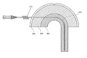
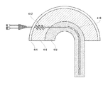
図1を参照すると、組織部位にカテーテル(100)を固定するために、いくつかの実施形態では、固定部(106)は組織構造へ固定するように設計されるコルク栓抜きのような螺旋体の構成をとるように湾曲され得る。この螺旋体は、周囲の組織との摩擦力を生み出すように設計される特定のピッチで離間された複数の曲り部を含むことができる。螺旋体の各曲り部は、一般的に、カテーテル部(104)の直径(104w)と実質的に同じ幅(106w)を有することができ、またはカテーテル(100)の残りに対しても同様である。固定部(106)の寸法およびピッチ距離は、螺旋体の曲り部と組織体の間の摩擦力を最適化するように構成され得る。例えば、カテーテルが最初に組織に挿入される時、螺旋体の部分の直径または幅(106d)は、カテーテル部(104)により開けられた開口部よりも実質的に大きくなることができ、それによって、螺旋体の固定部(106)の曲り部が、周囲の組織に固定されるように押しつけられ得ることが確実となる。いくつかの実施形態では、固定部(106)にもたらされる長さは、摩擦力を最適化するために十分であるべきであり、螺旋体の設計が提供されるが、決められた場所に装置が固定されるように固定部が前進することが可能な設計である限り、他の幾何学的設計が実施され得ることが認識されるだろう。いくつかの実施形態では、直径1mmのPVCでは、固定部(106)は、約2つから6つの曲り部を有することができ、その螺旋体の直径は、カテーテルの直径の約2〜6倍(例えば、約2〜6mm)になり、そして曲り部の間のピッチは、約2〜4mmになり得る。固定プロセス中に、カテーテル(100)が組織に挿入されるにつれて、固定部(106)が組織の少なくとも1つの層(すなわち皮膚の層)の真下に実質的に位置することができるまで、カテーテル(100)は右回りにまたは左回りに回転されてもよく、結果的に、複数の螺旋体の曲り部が、長手方向への移動に抵抗するのに十分な組織との摩擦力を生み出すことができる。少なくとも1つの螺旋体の曲り部を固定組織の近位に残すことによって、カテーテル(100)が摩擦力からの移動に抵抗することを可能にするだけでなく、カテーテル(100)が押力により被験者内へさらに前進することを防ぐ。固定部(106)が、移動に対して抵抗するのに十分な周囲の組織との摩擦力を生み出すことができる限り、任意の形状または寸法になり得ることが認識されるだろう。いくつかの実施形態では、一度カテーテル(100)が決められた場所に固定されると、流体は経路(108)を通って輸送され、当該経路(108)の第二部分(108b)は、流体が螺旋体の部分内の各曲り部を通って流れるように、螺旋体の部分の湾曲部になるように設計されてもよい。経路(108)の第二部分(108b)は、螺旋体の部分の曲り部内に完全に含まれ、そして経路(108)の第一部分(108a)と直接連通し得る。図1に示されるような固定部(106)は、螺旋体の部分の各曲り部の間で組織を効果的にとどまらせ、それにより、周囲の組織とカテーテル(100)の間の摩擦力を最適化する。さらに、曲り部の数および曲り部の間のピッチ距離はもちろんのこと、螺旋体の部分の長さおよび直径は、異なる解剖学的構造中にカテーテルをより良く固定するよう最適化され得る。1つの固定部のみが提供されるが、特定の適用が想定される程度まで、装置は複数の固定部分を提供され得ることが認識されるだろう。複数の固定部分が利用できることによっては、異なる組織の領域にわたる装置の固定を補助することができる。例えば、カテーテルは、2つの異なる解剖学的層(例えば、皮膚と筋膜)においてカテーテルを固定するために、2つ以上の固定部分を含んでもよい。固定部(106)の螺旋状のコルク栓抜きのような構造は、様々な方法で形成され得る。固定の役割を果たすために、固定部(106)は摩擦力の適用中に真っすぐになることに抵抗するように構成されてもよい。それゆえ、固定部(106)は、剛性を有するように設計してもよい。いくつかの実施形態の場合では、カテーテル(100)全体が実質的に剛性を有するようになってもよく、その場合には螺旋体の固定部(106)は、一般の技術(例えば、マンドレル曲げ加工法、加熱成形法、または初めからその形状に成形する方法)を使用してその部分を成型することにより1つの部品の一部として作られてもよい。カテーテル(104)の遠位の真っすぐな部分が実質的に可撓性を持ついくつかの実施形態では、装置は、螺旋体の部分をより剛性を有するような処理をすること、または装置を形成している時(例えば、押出し中)に材料を変更することにより、1つの部品から構築することができる。いくつかの実施形態では、カテーテル(104)は、遠位の真っすぐな部分が実質的に可撓性を持つようにし、および近位の螺旋体の部分をより剛性にする複数の部分から構築され得る。例えば、図1Bおよび図1Cで例証されるように、比較的に剛性を有する挿入体(120)が固定部(106)(可撓性を持っていてもよい)へ適用され、螺旋体成形部を作ることができる。または、図1Dおよび図1Eで例証されるように、螺旋形状を有するジャケット(122)が、固定部(106)をより剛性を有するようにするため、および固定部(106)を螺旋体を成形するためにカテーテルの固定部(106)に適用することができる。 Referring to FIG. 1, for anchoring a catheter (100) at a tissue site, in some embodiments, anchoring portion (106) is designed to anchor to tissue structures, such as a corkscrew-like spiral . Can be curved to take the configuration of. The helix may comprise a plurality of bent portions which are spaced at a certain pitch is designed to produce a frictional force between the surrounding tissue. Each bend in the helix is generally the same for the remaining catheter portion (104) in diameter can have an (104w) and substantially the same width (106 W), or catheter (100) is there. Size and pitch distance of the fixed portion (106) may be configured to optimize the frictional force between the organization bend of the helix. For example, when the catheter is first inserted into the tissue, the diameter or width of the portion of the helix (106d) may be substantially larger than the opening portion opened by the catheter section (104), whereby , bends of the fixed part of the helix (106) ensures that the may be pressed to be fixed to the surrounding tissue. In some embodiments, the length that is brought to the fixing unit (106) should be sufficient to optimize the frictional force, but the design of the spiral body is provided, in a predetermined location device It will be appreciated that other geometric designs may be implemented, as long as the fixture is a design that allows the fixture to be advanced so that it is fixed. In some embodiments, for PVC with a diameter of 1 mm, the anchor (106) can have about 2 to 6 bends , the diameter of the helix of which is about 2-6 times the diameter of the catheter. (E.g., about 2-6 mm), and the pitch between bends can be about 2-4 mm. During the fixation process, as the catheter (100) is inserted into the tissue, the fixation portion (106) can be positioned substantially beneath at least one layer of tissue (ie, the layer of skin) until the catheter (100) is substantially positioned. 100) may be rotated clockwise or counterclockwise, so that the bends of the multiple helices may produce sufficient frictional force with the tissue to resist longitudinal movement. it can. By leaving the proximal fixed tissue bends of at least one helix, not only to allow the catheter (100) to resist movement of the frictional force, the catheter (100) by pushing force subjects Prevent further progress inward. It will be appreciated that the fixation portion (106) can be of any shape or size as long as it can generate sufficient frictional force with the surrounding tissue to resist movement. In some embodiments, once the catheter (100) is secured in place, the fluid is transported through the pathway (108) and the second portion (108b) of the pathway (108) is so they flow through each bend in the part of the helix, may be designed such that the curved portion of the portion of the helix. Path second portion (108b) of the (108) is contained entirely within the bend portions of the spiral, and may communicate directly with the pathway first portion (108a) of the (108). Fixing portion as shown in FIG. 1 (106) is effectively allowed to remain tissue between the bend portions of the spiral, thereby, the frictional force between the surrounding tissue and the catheter (100) Optimize. Further, the pitch distance between the number and the bent portion of the bend, of course, the length and diameter of the portion of the helix, may be optimized to better secure the catheter in different anatomical structures. It will be appreciated that although only one fixation is provided, the device may be provided with multiple fixations to the extent that a particular application is envisioned. The availability of multiple anchoring portions can assist in anchoring the device across different tissue regions. For example, the catheter may include more than one anchoring portion to anchor the catheter in two different anatomical layers (eg, skin and fascia). The helical corkscrew-like structure of the fixation portion (106) can be formed in various ways. In order to act as a lock, the lock (106) may be configured to resist straightening during the application of frictional forces. Therefore, the fixed part (106) may be designed to be rigid. In the case of some embodiments, the catheter (100) entirely may be adapted to have a substantially rigid, fixed portion of the helical body when the (106) are generally technology (e.g., Mandrel Bend It may be made as part of one part by molding the part using a processing method, a thermoforming method, or a method of forming the shape from the beginning). In some embodiments straight portion of the distal catheter (104) has a substantially flexible, the device to the process as having a more rigid part of the helix, or forming a device It can be built from one piece by changing the material while it is running (eg during extrusion). Construction In some embodiments, the catheter (104) is straight portion of the distal is to have a substantially flexible, and the portion of the proximal helix more of a plurality of portions on rigid Can be done. For example, as illustrated in Figure 1B and 1C, applies insert a rigid relatively (120) to the fixed part (106) (flexibility may have a), spiral-forming unit Can be made. Or, as illustrated in Figure 1D and FIG. 1E, a jacket with a helical shape (122) is, in order to have the rigidity of the fixing unit (106), and a fixing portion (106) spiral shaped it can be applied to the fixing portion of the catheter (106) to.
Claims (8)
組織内に前進させるための実質的に真っすぐな部分;
細長い実質的に真っすぐな部分に続いて組織内へと前進させるための、実質的に真っすぐな部分の近位に位置する剛性を有する固定部であって、当該固定部は、カテーテルを組織に固定するために、固定部が内部に配置されている組織との長手方向への摩擦力をもたらすための、組織をそれらの間にとどまらせるように構成された複数の曲り部であって、充分な剛性によって回転運動を用いて組織内に前進させるように構成され、予め決められたピッチを備えた曲り部を有する、剛性を有する固定部;および、
流体を輸送するため、または器具の通路として役立つためにカテーテルを通って延びる経路であって、当該経路が、互いに流体連通する第一部分および第二部分を含み、当該第一部分が真っすぐな部分内をその長さに沿って延び、当該第二部分が固定部を通って延びる、経路、
を含む、カテーテル。 A catheter, wherein the catheter is
A substantially straight section for advancing into the organization ;
For advancing into Then the tissue elongate substantially straight portion, a fixed portion having a rigidity that is located proximal to the substantially straight part, the fixing part fixing the catheter to the tissue A plurality of bends configured to retain tissue between them to provide a longitudinal frictional force with the tissue in which the fixation portion is disposed. is configured to advance into the tissue using rotational motion by a rigid, has a bent portion having a predetermined pitch, the fixed portion having a stiffness; and,
A path extending through a catheter for transporting a fluid or to serve as a passageway for a device, the path including a first portion and a second portion in fluid communication with each other, the first portion within a straight portion . A path extending along its length, the second portion extending through the anchor,
Including a catheter.
あらかじめ決められた湾曲部を有する曲線状の部分を有する成形部材とカテーテルの真っすぐな部分を連結させる工程であって、当該真っすぐな部分が、あらかじめ決められた湾曲部に成形可能である可撓性な部分およびその真っすぐな部分を通って延びる経路を有し、当該経路が 成形部材の湾曲部を模倣する、工程;および
あらかじめ決められた湾曲部を呈するために真っすぐな部分の可撓性を有する部分を成形する工程;
を含み、
成形部材から真っすぐな部分を取り除くと、当該真っすぐな部分の可撓性な部分があらかじめ決められた湾曲部を維持する、方法。 A method for forming a catheter, the method comprising:
A step of connecting a straight member of a catheter with a molding member having a curved portion having a predetermined curved portion, wherein the straight portion can be molded into the predetermined curved portion. having a moiety and the path that extends through the straight portion, the path to mimic the curvature of the molded member, step, a flexible straight portion to exhibit and predetermined curvature Molding the part;
Including,
A method of removing a straight portion from a molded member, wherein the flexible portion of the straight portion maintains a predetermined bend.
Applications Claiming Priority (3)
| Application Number | Priority Date | Filing Date | Title |
|---|---|---|---|
| US201462085838P | 2014-12-01 | 2014-12-01 | |
| US62/085,838 | 2014-12-01 | ||
| PCT/US2015/063221 WO2016089894A1 (en) | 2014-12-01 | 2015-12-01 | Self-anchoring catheters and methods of use |
Related Child Applications (2)
| Application Number | Title | Priority Date | Filing Date |
|---|---|---|---|
| JP2019008109A Division JP7104640B2 (en) | 2014-12-01 | 2019-01-21 | Self-fixing catheter and how to use it |
| JP2020080451A Division JP7065904B2 (en) | 2014-12-01 | 2020-04-30 | Self-fixing catheter and how to use it |
Publications (3)
| Publication Number | Publication Date |
|---|---|
| JP2017536908A JP2017536908A (en) | 2017-12-14 |
| JP2017536908A5 true JP2017536908A5 (en) | 2020-06-25 |
| JP7037361B2 JP7037361B2 (en) | 2022-03-16 |
Family
ID=56078513
Family Applications (3)
| Application Number | Title | Priority Date | Filing Date |
|---|---|---|---|
| JP2017530180A Active JP7037361B2 (en) | 2014-12-01 | 2015-12-01 | Self-fixing catheter and how to use it |
| JP2019008109A Active JP7104640B2 (en) | 2014-12-01 | 2019-01-21 | Self-fixing catheter and how to use it |
| JP2020080451A Active JP7065904B2 (en) | 2014-12-01 | 2020-04-30 | Self-fixing catheter and how to use it |
Family Applications After (2)
| Application Number | Title | Priority Date | Filing Date |
|---|---|---|---|
| JP2019008109A Active JP7104640B2 (en) | 2014-12-01 | 2019-01-21 | Self-fixing catheter and how to use it |
| JP2020080451A Active JP7065904B2 (en) | 2014-12-01 | 2020-04-30 | Self-fixing catheter and how to use it |
Country Status (7)
| Country | Link |
|---|---|
| US (4) | US10252034B2 (en) |
| EP (1) | EP3226955A4 (en) |
| JP (3) | JP7037361B2 (en) |
| CN (2) | CN113521503A (en) |
| AU (1) | AU2015355062B2 (en) |
| CA (1) | CA2969448A1 (en) |
| WO (1) | WO2016089894A1 (en) |
Families Citing this family (9)
| Publication number | Priority date | Publication date | Assignee | Title |
|---|---|---|---|---|
| CN113521503A (en) | 2014-12-01 | 2021-10-22 | 帕夫梅德有限公司 | Self-anchoring catheter and method of use |
| SG10201602007WA (en) * | 2015-04-20 | 2016-11-29 | Biotronik Se & Co Kg | Implantable curved shaping part for externally shaping an implantable electrode line or a catheter |
| SG10201602009PA (en) * | 2015-04-20 | 2016-11-29 | Biotronik Se & Co Kg | Implantable curved shaping part for externally shaping an implantable electrode line or a catheter |
| WO2018125845A1 (en) | 2016-12-27 | 2018-07-05 | Vasonics, Llc | Catheter housing |
| CN110325122B (en) * | 2017-02-28 | 2024-03-19 | 波士顿科学国际有限公司 | Hinge pin |
| AU2019408052A1 (en) * | 2018-12-21 | 2021-07-08 | National University Of Ireland, Galway | A medical anchor device |
| WO2021026641A1 (en) * | 2019-08-09 | 2021-02-18 | Safa Behnam | Coiled over-the-needle catheter and methods of use thereof for performing continuous nerve block procedures |
| WO2022256307A1 (en) * | 2021-06-03 | 2022-12-08 | PAVmed Inc. | Adjustable self-anchoring catheters and methods of use |
| GB2623022A (en) * | 2021-07-26 | 2024-04-03 | Interrad Medical Inc | Securing a catheter device |
Family Cites Families (56)
| Publication number | Priority date | Publication date | Assignee | Title |
|---|---|---|---|---|
| US3461869A (en) | 1966-04-05 | 1969-08-19 | Bio Medical Systems Inc | Permanent skin exit device |
| US3719737A (en) * | 1970-12-09 | 1973-03-06 | Bard Inc C R | Method of making a preformed curved epidural catheter |
| US3890970A (en) * | 1974-01-21 | 1975-06-24 | Robert L Gullen | Retention cannula or catheter and applicator |
| US4534761A (en) | 1981-08-14 | 1985-08-13 | Bentley Laboratories, Inc. | Implant device |
| JPS58149765A (en) * | 1981-11-27 | 1983-09-06 | フレセニウス・ア−ゲ− | Abdominal membrane cathetel |
| CA1245931A (en) | 1984-09-21 | 1988-12-06 | Sophia Pesotchinsky | Positionable tissue interfacing device for the management of percutaneous conduits |
| SE445518B (en) | 1985-02-27 | 1986-06-30 | Inst Applied Biotechnology | BUKVEGGSGENOMFORING |
| GB8814898D0 (en) * | 1988-06-22 | 1988-07-27 | Evans J M | Catheters & methods of manufacture |
| US5964744A (en) | 1993-01-04 | 1999-10-12 | Menlo Care, Inc. | Polymeric medical device systems having shape memory |
| US5582616A (en) | 1994-08-05 | 1996-12-10 | Origin Medsystems, Inc. | Surgical helical fastener with applicator |
| US5797870A (en) * | 1995-06-07 | 1998-08-25 | Indiana University Foundation | Pericardial delivery of therapeutic and diagnostic agents |
| US6546280B2 (en) * | 1996-06-18 | 2003-04-08 | Cook Incorporated | Indwelling catheter |
| US6416510B1 (en) * | 1997-03-13 | 2002-07-09 | Biocardia, Inc. | Drug delivery catheters that attach to tissue and methods for their use |
| US5984896A (en) | 1997-10-28 | 1999-11-16 | Ojp #73, Inc. | Fixated catheter |
| US6309370B1 (en) * | 1998-02-05 | 2001-10-30 | Biosense, Inc. | Intracardiac drug delivery |
| US6623473B1 (en) * | 1998-06-04 | 2003-09-23 | Biosense Webster, Inc. | Injection catheter with multi-directional delivery injection needle |
| WO2000029056A2 (en) * | 1998-11-19 | 2000-05-25 | Corvascular, Inc. | Coronary infusion catheter and intra-coronary drug administration methods |
| JP3524788B2 (en) * | 1998-12-24 | 2004-05-10 | 株式会社パイオラックス | Indwelling catheter for administration of anticancer drugs |
| US6569143B2 (en) * | 1999-10-14 | 2003-05-27 | Becton, Dickinson And Company | Method of intradermally injecting substances |
| US6595958B1 (en) * | 2000-08-08 | 2003-07-22 | Scimed Life Systems, Inc. | Tortuous path injection device and method |
| JP2002191699A (en) * | 2000-12-22 | 2002-07-09 | Terumo Corp | Introduction sheath positioning instrument |
| US8075630B2 (en) | 2001-09-06 | 2011-12-13 | Bio-Lok International, Inc. | Transcutaneous port having micro-textured surfaces for tissue and bone integration |
| US20030055381A1 (en) | 2001-09-17 | 2003-03-20 | Wilkinson Bradley M. | Medical devices |
| US7846148B2 (en) * | 2001-09-20 | 2010-12-07 | Boston Scientific Scimed, Inc. | Catheter having increased curve performance through heat treatment |
| US6743209B2 (en) | 2002-07-12 | 2004-06-01 | John Howell Brown | Catheter with integral anchoring means |
| US7662145B2 (en) | 2003-09-17 | 2010-02-16 | Prostalund Operations Ab | Partial-length indwelling urinary catheter and method permitting selective urine discharge |
| US8382786B2 (en) * | 2004-10-27 | 2013-02-26 | Petrus A. Besselink | Self-activating endoluminal device |
| JP5586147B2 (en) * | 2005-09-12 | 2014-09-10 | ブリッジポイント、メディカル、インコーポレイテッド | Intravascular device for utilizing the space in the wall |
| JP2007236628A (en) * | 2006-03-08 | 2007-09-20 | Terumo Corp | Medical tube introduction implement |
| US8442656B2 (en) * | 2006-06-02 | 2013-05-14 | Cardiac Pacemakers, Inc. | Cardiac lead having implantable stiffening structures for fixation |
| WO2008027371A2 (en) * | 2006-08-29 | 2008-03-06 | Surmodics, Inc. | Low profile bioactive agent delivery device |
| US20080108950A1 (en) * | 2006-11-03 | 2008-05-08 | Rioux Robert F | Corkscrew helical inserter port |
| JP5562648B2 (en) * | 2007-01-29 | 2014-07-30 | スパイナル・モデュレーション・インコーポレイテッド | Non-stitched top retaining mechanism |
| CN101896220A (en) | 2007-10-08 | 2010-11-24 | 瑞尼斯豪(爱尔兰)有限公司 | Catheter |
| GB0802634D0 (en) | 2008-02-13 | 2008-03-19 | Renishaw Plc | Catheter |
| US20090105659A1 (en) | 2007-10-17 | 2009-04-23 | Tyco Healthcare Group Lp | Anchoring cannula |
| CN201094764Y (en) * | 2007-10-23 | 2008-08-06 | 中国人民解放军第二军医大学 | Artery blood cannulation with sacculus |
| US7824377B2 (en) * | 2007-12-21 | 2010-11-02 | St. Jude Medical, Atrial Fibrillation Division, Inc. | Tissue anchoring catheter systems and methods |
| EP2092943A1 (en) | 2008-02-21 | 2009-08-26 | Universität Bern | Implantable access for removal and/or return of fluids |
| US20090275894A1 (en) * | 2008-05-01 | 2009-11-05 | Curtis Guy P | Transvenous soaker catheter |
| ES2525525T3 (en) * | 2008-08-22 | 2014-12-26 | C.R. Bard, Inc. | Catheter assembly that includes ECG and magnetic sensor assemblies |
| US20110054448A1 (en) | 2009-08-28 | 2011-03-03 | Navilyst Medical, Inc. | Medical device containing catheter anchoring feature |
| EP2473123B1 (en) * | 2009-09-03 | 2019-01-30 | Boston Scientific Limited | Lancet micro-catheter |
| US8496644B2 (en) * | 2009-12-17 | 2013-07-30 | Angiodynamics, Inc. | Drainage catheter tip shape configuration |
| AU2010336956A1 (en) | 2009-12-30 | 2012-07-19 | Cook Medical Technologies Llc | Gastric port system |
| EP2593028B1 (en) * | 2010-09-15 | 2017-08-16 | Icecure Medical Ltd. | Cryosurgical instrument for treating large volume of tissue |
| US8940002B2 (en) | 2010-09-30 | 2015-01-27 | Kardium Inc. | Tissue anchor system |
| GB201017247D0 (en) * | 2010-10-13 | 2010-11-24 | Islam Abul B M | Injection port for intra-marrow injection/fusion |
| CN202665687U (en) * | 2010-10-25 | 2013-01-16 | 美敦力Af卢森堡有限责任公司 | Catheter device used for treatment of human patient via renal denervation |
| CN201862119U (en) * | 2010-11-25 | 2011-06-15 | 王俊平 | Gastrointestinal decompression and naso-gastrojejunal nutrition composite tube |
| US8486009B2 (en) | 2011-06-20 | 2013-07-16 | Hue-Teh Shih | Systems and methods for steering catheters |
| US8932263B2 (en) | 2012-02-17 | 2015-01-13 | Interrad Medical, Inc. | Anchoring an intravenous cannula |
| JP6347452B2 (en) | 2012-10-01 | 2018-06-27 | キューマックス,エルエルシー | Spiral balloon catheter |
| CN105792877B (en) | 2013-09-30 | 2019-09-27 | 比尔卡地亚股份有限公司 | Radial artery and through internal membrane of heart delivery catheter |
| US9737696B2 (en) * | 2014-01-15 | 2017-08-22 | Tufts Medical Center, Inc. | Endovascular cerebrospinal fluid shunt |
| CN113521503A (en) | 2014-12-01 | 2021-10-22 | 帕夫梅德有限公司 | Self-anchoring catheter and method of use |
-
2015
- 2015-12-01 CN CN202110794459.3A patent/CN113521503A/en active Pending
- 2015-12-01 CN CN201580065441.2A patent/CN107106813A/en active Pending
- 2015-12-01 AU AU2015355062A patent/AU2015355062B2/en active Active
- 2015-12-01 WO PCT/US2015/063221 patent/WO2016089894A1/en active Application Filing
- 2015-12-01 JP JP2017530180A patent/JP7037361B2/en active Active
- 2015-12-01 CA CA2969448A patent/CA2969448A1/en active Pending
- 2015-12-01 US US14/956,141 patent/US10252034B2/en active Active
- 2015-12-01 EP EP15865776.7A patent/EP3226955A4/en not_active Withdrawn
-
2019
- 2019-01-18 US US16/251,372 patent/US20190151618A1/en active Pending
- 2019-01-18 US US16/251,397 patent/US11511081B2/en active Active
- 2019-01-18 US US16/251,411 patent/US20190151620A1/en not_active Abandoned
- 2019-01-21 JP JP2019008109A patent/JP7104640B2/en active Active
-
2020
- 2020-04-30 JP JP2020080451A patent/JP7065904B2/en active Active
Similar Documents
| Publication | Publication Date | Title |
|---|---|---|
| JP2017536908A5 (en) | ||
| JP2019088839A5 (en) | ||
| US11654264B2 (en) | Guide for intravascular device | |
| JP7225306B2 (en) | Stent with Dual Tissue Wall Anchoring Mechanism | |
| JP5068527B2 (en) | Stent delivery system with improved delivery force distribution | |
| JP7104640B2 (en) | Self-fixing catheter and how to use it | |
| JP5724382B2 (en) | catheter | |
| JP6983142B6 (en) | Ureteral stent | |
| US8652146B2 (en) | Shapeable retrieval device and method of using | |
| JP6153011B2 (en) | Non-slip stent manufacturing method | |
| JP2019504746A (en) | Endovascular treatment site access | |
| CN110536712A (en) | System for delivery conduit | |
| JP2012532687A5 (en) | ||
| US8685047B2 (en) | Scaffold device for preventing tissue trauma | |
| CA2946789A1 (en) | Biliary stent | |
| JP2010506685A5 (en) | ||
| JP2019141607A (en) | Dilator system and method | |
| BR102012002370B1 (en) | device to install and remove a self-expanding intravascular stent with a flexible sheathed wire | |
| US20110319979A1 (en) | Stent and method of mounting the same | |
| EP2818141B1 (en) | Stent kit | |
| US9839767B2 (en) | Catheter | |
| US9039637B2 (en) | Flexible cytology coil | |
| US20150088151A1 (en) | Elongated member for medical use and connecting member | |
| JP6633513B2 (en) | Catheter and catheter set | |
| JP6565169B2 (en) | Support catheter |