JP2017536583A - Driving method of pixel array - Google Patents
Driving method of pixel array Download PDFInfo
- Publication number
- JP2017536583A JP2017536583A JP2017542239A JP2017542239A JP2017536583A JP 2017536583 A JP2017536583 A JP 2017536583A JP 2017542239 A JP2017542239 A JP 2017542239A JP 2017542239 A JP2017542239 A JP 2017542239A JP 2017536583 A JP2017536583 A JP 2017536583A
- Authority
- JP
- Japan
- Prior art keywords
- pixel
- sub
- pixels
- pixel unit
- unit
- Prior art date
- Legal status (The legal status is an assumption and is not a legal conclusion. Google has not performed a legal analysis and makes no representation as to the accuracy of the status listed.)
- Pending
Links
- 238000000034 method Methods 0.000 title claims abstract description 30
- 239000003086 colorant Substances 0.000 claims abstract description 9
- 238000000638 solvent extraction Methods 0.000 claims abstract description 4
- 238000005070 sampling Methods 0.000 claims description 23
- 229910003460 diamond Inorganic materials 0.000 claims description 16
- 239000010432 diamond Substances 0.000 claims description 16
- 238000003491 array Methods 0.000 claims description 2
- 230000000694 effects Effects 0.000 description 6
- 239000011159 matrix material Substances 0.000 description 4
- 238000010586 diagram Methods 0.000 description 2
- 238000004519 manufacturing process Methods 0.000 description 2
- 238000012986 modification Methods 0.000 description 1
- 230000004048 modification Effects 0.000 description 1
- 239000000126 substance Substances 0.000 description 1
- 230000000007 visual effect Effects 0.000 description 1
Images
Classifications
-
- G—PHYSICS
- G09—EDUCATION; CRYPTOGRAPHY; DISPLAY; ADVERTISING; SEALS
- G09G—ARRANGEMENTS OR CIRCUITS FOR CONTROL OF INDICATING DEVICES USING STATIC MEANS TO PRESENT VARIABLE INFORMATION
- G09G5/00—Control arrangements or circuits for visual indicators common to cathode-ray tube indicators and other visual indicators
- G09G5/02—Control arrangements or circuits for visual indicators common to cathode-ray tube indicators and other visual indicators characterised by the way in which colour is displayed
-
- G—PHYSICS
- G09—EDUCATION; CRYPTOGRAPHY; DISPLAY; ADVERTISING; SEALS
- G09G—ARRANGEMENTS OR CIRCUITS FOR CONTROL OF INDICATING DEVICES USING STATIC MEANS TO PRESENT VARIABLE INFORMATION
- G09G3/00—Control arrangements or circuits, of interest only in connection with visual indicators other than cathode-ray tubes
- G09G3/20—Control arrangements or circuits, of interest only in connection with visual indicators other than cathode-ray tubes for presentation of an assembly of a number of characters, e.g. a page, by composing the assembly by combination of individual elements arranged in a matrix no fixed position being assigned to or needed to be assigned to the individual characters or partial characters
- G09G3/2003—Display of colours
-
- G—PHYSICS
- G09—EDUCATION; CRYPTOGRAPHY; DISPLAY; ADVERTISING; SEALS
- G09G—ARRANGEMENTS OR CIRCUITS FOR CONTROL OF INDICATING DEVICES USING STATIC MEANS TO PRESENT VARIABLE INFORMATION
- G09G5/00—Control arrangements or circuits for visual indicators common to cathode-ray tube indicators and other visual indicators
- G09G5/10—Intensity circuits
-
- G—PHYSICS
- G09—EDUCATION; CRYPTOGRAPHY; DISPLAY; ADVERTISING; SEALS
- G09G—ARRANGEMENTS OR CIRCUITS FOR CONTROL OF INDICATING DEVICES USING STATIC MEANS TO PRESENT VARIABLE INFORMATION
- G09G5/00—Control arrangements or circuits for visual indicators common to cathode-ray tube indicators and other visual indicators
- G09G5/14—Display of multiple viewports
-
- G—PHYSICS
- G09—EDUCATION; CRYPTOGRAPHY; DISPLAY; ADVERTISING; SEALS
- G09G—ARRANGEMENTS OR CIRCUITS FOR CONTROL OF INDICATING DEVICES USING STATIC MEANS TO PRESENT VARIABLE INFORMATION
- G09G2300/00—Aspects of the constitution of display devices
- G09G2300/04—Structural and physical details of display devices
- G09G2300/0439—Pixel structures
- G09G2300/0452—Details of colour pixel setup, e.g. pixel composed of a red, a blue and two green components
-
- G—PHYSICS
- G09—EDUCATION; CRYPTOGRAPHY; DISPLAY; ADVERTISING; SEALS
- G09G—ARRANGEMENTS OR CIRCUITS FOR CONTROL OF INDICATING DEVICES USING STATIC MEANS TO PRESENT VARIABLE INFORMATION
- G09G2300/00—Aspects of the constitution of display devices
- G09G2300/04—Structural and physical details of display devices
- G09G2300/0439—Pixel structures
- G09G2300/0465—Improved aperture ratio, e.g. by size reduction of the pixel circuit, e.g. for improving the pixel density or the maximum displayable luminance or brightness
-
- G—PHYSICS
- G09—EDUCATION; CRYPTOGRAPHY; DISPLAY; ADVERTISING; SEALS
- G09G—ARRANGEMENTS OR CIRCUITS FOR CONTROL OF INDICATING DEVICES USING STATIC MEANS TO PRESENT VARIABLE INFORMATION
- G09G2320/00—Control of display operating conditions
- G09G2320/02—Improving the quality of display appearance
- G09G2320/0257—Reduction of after-image effects
-
- G—PHYSICS
- G09—EDUCATION; CRYPTOGRAPHY; DISPLAY; ADVERTISING; SEALS
- G09G—ARRANGEMENTS OR CIRCUITS FOR CONTROL OF INDICATING DEVICES USING STATIC MEANS TO PRESENT VARIABLE INFORMATION
- G09G2320/00—Control of display operating conditions
- G09G2320/06—Adjustment of display parameters
- G09G2320/0626—Adjustment of display parameters for control of overall brightness
-
- G—PHYSICS
- G09—EDUCATION; CRYPTOGRAPHY; DISPLAY; ADVERTISING; SEALS
- G09G—ARRANGEMENTS OR CIRCUITS FOR CONTROL OF INDICATING DEVICES USING STATIC MEANS TO PRESENT VARIABLE INFORMATION
- G09G2340/00—Aspects of display data processing
- G09G2340/04—Changes in size, position or resolution of an image
- G09G2340/0407—Resolution change, inclusive of the use of different resolutions for different screen areas
-
- G—PHYSICS
- G09—EDUCATION; CRYPTOGRAPHY; DISPLAY; ADVERTISING; SEALS
- G09G—ARRANGEMENTS OR CIRCUITS FOR CONTROL OF INDICATING DEVICES USING STATIC MEANS TO PRESENT VARIABLE INFORMATION
- G09G2340/00—Aspects of display data processing
- G09G2340/04—Changes in size, position or resolution of an image
- G09G2340/0442—Handling or displaying different aspect ratios, or changing the aspect ratio
-
- G—PHYSICS
- G09—EDUCATION; CRYPTOGRAPHY; DISPLAY; ADVERTISING; SEALS
- G09G—ARRANGEMENTS OR CIRCUITS FOR CONTROL OF INDICATING DEVICES USING STATIC MEANS TO PRESENT VARIABLE INFORMATION
- G09G2340/00—Aspects of display data processing
- G09G2340/04—Changes in size, position or resolution of an image
- G09G2340/0457—Improvement of perceived resolution by subpixel rendering
Landscapes
- Engineering & Computer Science (AREA)
- Physics & Mathematics (AREA)
- Computer Hardware Design (AREA)
- General Physics & Mathematics (AREA)
- Theoretical Computer Science (AREA)
- Devices For Indicating Variable Information By Combining Individual Elements (AREA)
- Control Of Indicators Other Than Cathode Ray Tubes (AREA)
- Electroluminescent Light Sources (AREA)
- Liquid Crystal (AREA)
Abstract
本発明は、横縦比が1:2乃至1:1の間にある異なる色の複数のサブ画素を有する複数の画素ユニットを含む画素アレイの駆動方法を提供する。前記駆動方法は、表示される画像を複数の色分量を有する複数の理論的な画素ユニットに区画するステップと、区画された各理論的な画素ユニットの色分量に基づき、各画素ユニットの各サブ画素の輝度値を算出するステップとを含む。The present invention provides a driving method of a pixel array including a plurality of pixel units having a plurality of sub-pixels of different colors having an aspect ratio of 1: 2 to 1: 1. The driving method includes a step of partitioning an image to be displayed into a plurality of theoretical pixel units having a plurality of color components, and each sub-unit of each pixel unit based on the color components of each theoretical pixel unit partitioned. Calculating a luminance value of the pixel.
Description
本発明は表示技術分野に属し、具体的には画素アレイの駆動方法に関する。 The present invention belongs to the field of display technology, and specifically relates to a method for driving a pixel array.
現在の表示パネルでは、よく見られる画素設計は、3つのサブ画素(例えば、図1に示されたように、赤色サブ画素、緑色サブ画素及び青色サブ画素)又は4つのサブ画素(例えば、赤色サブ画素、緑色サブ画素、青色サブ画素及び白色サブ画素)により1つの画素ユニットを構成することによって表示を行う。物理解像度は即ち視覚解像度である。 In current display panels, common pixel designs are three sub-pixels (eg, red sub-pixel, green sub-pixel and blue sub-pixel as shown in FIG. 1) or four sub-pixels (eg red Display is performed by forming one pixel unit by subpixels, green subpixels, blue subpixels, and white subpixels). Physical resolution is visual resolution.
仮に、表示パネルのインチ当たりの画素(pixel per inch,PPI)が比較的低いと、表示画面を見る時に、ユーザは明確に粒状感を感じる(即ち、表示される画像のエッジはスムーズではなく、鋸歯状を呈する)。表示画面の視聴体験に対するユーザの要求の増加に伴って、表示画面のPPIの増加が要される。表示画面のPPIの増加は表示パネルを製造するプロセスの難しさの増加をもたらす。 If the pixel per inch (PPI) of the display panel is relatively low, the user clearly feels grain when viewing the display screen (ie, the edge of the displayed image is not smooth, (Sawtooth shape) With an increase in user demand for the viewing experience of the display screen, an increase in the PPI of the display screen is required. An increase in the PPI of the display screen leads to an increase in the difficulty of the process for manufacturing the display panel.
製造プロセスの難しさを増やさない(即ち、PPIを増やさない)状況において、如何にして表示画面の粒状感を低減することにより、同一の寸法でより高い解像度を有する表示パネルの表示効果に達するかは、本分野のいますぐに解決しなければならない課題となる。 In a situation where the difficulty of the manufacturing process is not increased (ie, the PPI is not increased), how can the display effect of a display panel with the same dimensions and higher resolution be achieved by reducing the granularity of the display screen? Is an issue that must be resolved in the field.
本発明の解決しようとする技術課題は以下を含む。即ち、従来の画素アレイに存在する課題に対して、駆動方法を提供し、この駆動方法を用いて画素アレイを駆動することにより表示パネルの粒状感を低減でき、同一の寸法でより高い解像度を有する表示パネルの表示効果を達成する。 Technical problems to be solved by the present invention include the following. In other words, a driving method is provided for the problems existing in the conventional pixel array, and the graininess of the display panel can be reduced by driving the pixel array using this driving method, and a higher resolution can be achieved with the same dimensions. The display effect of the display panel having is achieved.
本発明に基づき、横縦比が1:2乃至1:1の間にある異なる色の複数のサブ画素を有する複数の画素ユニットを含む画素アレイの駆動方法が提供される。前記駆動方法は、表示される画像を複数の色分量を有する複数の理論的な画素ユニットに区画するステップと、区画された各理論的な画素ユニットの色分量に基づき、各画素ユニットの各サブ画素の輝度値を算出するステップとを含む。各サブ画素の輝度値を算出するステップは、各サブ画素に、該サブ画素の中心を中心とし、該サブ画素と同行又は同列であり且つ同じ色を有する隣接的なサブ画素の中心と該サブ画素の中心とのラインの中間点を夫々4つの頂点とするひし形サンプリング領域を区画するサブステップと、各理論的な画素ユニットと該サブ画素のひし形サンプリング領域との重なり面積と、該ひし形サンプリング領域の面積との比を、該サブ画素のひし形サンプリング領域に対する該理論的な画素ユニットの面積割合として算出するサブステップと、該サブ画素のひし形サンプリング領域に対する各理論的な画素ユニットの面積割合に、該サブ画素と同じ色の該理論的な画素ユニットの色分量を掛けて得られる各積の和を該サブ画素の輝度値とするサブステップとを含む。 In accordance with the present invention, there is provided a driving method of a pixel array including a plurality of pixel units having a plurality of sub-pixels of different colors having an aspect ratio of 1: 2 to 1: 1. The driving method includes a step of partitioning an image to be displayed into a plurality of theoretical pixel units having a plurality of color components, and each sub-unit of each pixel unit based on the color components of each theoretical pixel unit partitioned. Calculating a luminance value of the pixel. The step of calculating the luminance value of each sub-pixel includes, for each sub-pixel, the center of the sub-pixel and the center of the adjacent sub-pixel having the same color and the same row or column as the sub-pixel. A sub-step for defining a rhombus sampling area having four vertices at the midpoint of the line with the center of the pixel, an overlapping area between each theoretical pixel unit and the rhombus sampling area of the sub-pixel, and the rhombus sampling area Sub-step of calculating the ratio of the area to the rhomboidal sampling area of the subpixel as a ratio of the area of the theoretical pixel unit to the rhomboidal sampling area of the subpixel, A sub-step in which the sum of each product obtained by multiplying the color amount of the theoretical pixel unit of the same color as the sub-pixel is the luminance value of the sub-pixel. Including the door.
本発明の実施例に基づき、前記画素ユニットは横縦比が2:3であり異なる色を有する3つのサブ画素を含んでもよい。 According to an embodiment of the present invention, the pixel unit may include three sub-pixels having an aspect ratio of 2: 3 and different colors.
本発明の実施例に基づき、前記画素アレイは、同一の列に位置し、次の行の画素ユニットのサブ画素の左境界と上の行の画素ユニットのサブ画素の下境界の中間点が合わせられ、又は上の行の画素ユニットのサブ画素の左境界と次の行の画素ユニットのサブ画素の上境界の中間点が合わせられるような2つの隣接する画素ユニットを有する複数の画素グループを含む。 According to an embodiment of the present invention, the pixel arrays are located in the same column, and the midpoint between the left boundary of the subpixel of the pixel unit of the next row and the lower boundary of the subpixel of the pixel unit of the upper row is aligned. Or a plurality of pixel groups having two adjacent pixel units such that the midpoint between the left boundary of the sub-pixels of the upper row pixel unit and the upper boundary of the sub-pixel of the next row pixel unit is aligned .
本発明の実施例に基づき、前記画素グループは以下の各種配列方式における一種又は多種の方式により配列される。即ち、(1)上の行の画素ユニットのサブ画素は赤色サブ画素、青色サブ画素及び緑色サブ画素であり、次の行の画素ユニットのサブ画素は緑色サブ画素、赤色サブ画素及び青色サブ画素であり、且つ次の行の画素ユニットのサブ画素の左境界と上の行の画素ユニットのサブ画素の下境界の中間点は合わせられる。(2)上の行の画素ユニットのサブ画素は青色サブ画素、赤色サブ画素及び緑色サブ画素であり、次の行の画素ユニットのサブ画素は緑色サブ画素、青色サブ画素及び赤色サブ画素であり、且つ次の行の画素ユニットのサブ画素の左境界と上の行の画素ユニットのサブ画素の下境界の中間点は合わせられる。(3)上の行の画素ユニットのサブ画素は青色サブ画素、緑色サブ画素及び赤色サブ画素であり、次の行の画素ユニットのサブ画素は赤色サブ画素、青色サブ画素及び緑色サブ画素であり、且つ次の行の画素ユニットのサブ画素の左境界と上の行の画素ユニットのサブ画素の下境界の中間点は合わせられる。(4)上の行の画素ユニットのサブ画素は緑色サブ画素、青色サブ画素及び赤色サブ画素であり、次の行の画素ユニットのサブ画素は赤色サブ画素、緑色サブ画素及び青色サブ画素であり、且つ次の行の画素ユニットのサブ画素の左境界と上の行の画素ユニットのサブ画素の下境界の中間点は合わせられる。(5)上の行の画素ユニットのサブ画素は緑色サブ画素、赤色サブ画素及び青色サブ画素であり、次の行の画素ユニットのサブ画素は青色サブ画素、緑色サブ画素及び赤色サブ画素であり、且つ次の行の画素ユニットのサブ画素の左境界と上の行の画素ユニットのサブ画素の下境界の中間点は合わせられる。(6)上の行の画素ユニットのサブ画素は赤色サブ画素、緑色サブ画素及び青色サブ画素であり、次の行の画素ユニットのサブ画素は青色サブ画素、赤色サブ画素及び緑色サブ画素であり、且つ次の行の画素ユニットのサブ画素の左境界と上の行の画素ユニットのサブ画素の下境界の中間点は合わせられる。(7)上の行の画素ユニットのサブ画素は緑色サブ画素、赤色サブ画素及び青色サブ画素であり、次の行の画素ユニットのサブ画素は赤色サブ画素、青色サブ画素及び緑色サブ画素であり、且つ上の行の画素ユニットのサブ画素の左境界と次の行の画素ユニットのサブ画素の上境界の中間点は合わせられる。(8)上の行の画素ユニットのサブ画素は緑色サブ画素、青色サブ画素及び赤色サブ画素であり、次の行の画素ユニットのサブ画素は青色サブ画素、赤色サブ画素及び緑色サブ画素であり、且つ上の行の画素ユニットのサブ画素の左境界と次の行の画素ユニットのサブ画素の上境界の中間点は合わせられる。(9)上の行の画素ユニットのサブ画素は赤色サブ画素、青色サブ画素及び緑色サブ画素であり、次の行の画素ユニットのサブ画素は青色サブ画素、緑色サブ画素及び赤色サブ画素であり、且つ上の行の画素ユニットのサブ画素の左境界と次の行の画素ユニットのサブ画素の上境界の中間点は合わせられる。(10)上の行の画素ユニットのサブ画素は赤色サブ画素、緑色サブ画素及び青色サブ画素であり、次の行の画素ユニットのサブ画素は緑色サブ画素、青色サブ画素及び赤色サブ画素であり、且つ上の行の画素ユニットのサブ画素の左境界と次の行の画素ユニットのサブ画素の上境界の中間点は合わせられる。(11)上の行の画素ユニットのサブ画素は青色サブ画素、緑色サブ画素及び赤色サブ画素であり、次の行の画素ユニットのサブ画素は緑色サブ画素、赤色サブ画素及び青色サブ画素であり、且つ上の行の画素ユニットのサブ画素の左境界と次の行の画素ユニットのサブ画素の上境界の中間点は合わせられる。(12)上の行の画素ユニットのサブ画素は青色サブ画素、赤色サブ画素及び緑色サブ画素であり、次の行の画素ユニットのサブ画素は赤色サブ画素、緑色サブ画素及び青色サブ画素であり、且つ上の行の画素ユニットのサブ画素の左境界と次の行の画素ユニットのサブ画素の上境界の中間点は合わせられる。 According to an embodiment of the present invention, the pixel groups are arranged by one or various methods in the following various arrangement methods. That is, (1) the sub-pixels of the pixel unit in the upper row are a red sub-pixel, a blue sub-pixel, and a green sub-pixel, and the sub-pixels of the pixel unit in the next row are a green sub-pixel, a red sub-pixel, and a blue sub-pixel. And the midpoint of the left boundary of the sub-pixel of the pixel unit in the next row and the lower boundary of the sub-pixel of the pixel unit in the upper row are matched. (2) The sub-pixels of the pixel unit in the upper row are a blue sub-pixel, a red sub-pixel, and a green sub-pixel, and the sub-pixels of the pixel unit in the next row are a green sub-pixel, a blue sub-pixel, and a red sub-pixel. In addition, the midpoint of the left boundary of the sub-pixel of the pixel unit in the next row and the lower boundary of the sub-pixel of the pixel unit in the upper row are matched. (3) The sub-pixels of the pixel unit in the upper row are a blue sub-pixel, a green sub-pixel, and a red sub-pixel, and the sub-pixels of the pixel unit in the next row are a red sub-pixel, a blue sub-pixel, and a green sub-pixel. In addition, the midpoint of the left boundary of the sub-pixel of the pixel unit in the next row and the lower boundary of the sub-pixel of the pixel unit in the upper row are matched. (4) The sub-pixels of the pixel unit in the upper row are a green sub-pixel, a blue sub-pixel, and a red sub-pixel, and the sub-pixels of the pixel unit in the next row are a red sub-pixel, a green sub-pixel, and a blue sub-pixel. In addition, the midpoint of the left boundary of the sub-pixel of the pixel unit in the next row and the lower boundary of the sub-pixel of the pixel unit in the upper row are matched. (5) The sub-pixels of the pixel unit in the upper row are a green sub-pixel, a red sub-pixel, and a blue sub-pixel, and the sub-pixels of the pixel unit in the next row are a blue sub-pixel, a green sub-pixel, and a red sub-pixel. In addition, the midpoint of the left boundary of the sub-pixel of the pixel unit in the next row and the lower boundary of the sub-pixel of the pixel unit in the upper row are matched. (6) The sub-pixels of the pixel unit in the upper row are a red sub-pixel, a green sub-pixel, and a blue sub-pixel, and the sub-pixels of the pixel unit in the next row are a blue sub-pixel, a red sub-pixel, and a green sub-pixel. In addition, the midpoint of the left boundary of the sub-pixel of the pixel unit in the next row and the lower boundary of the sub-pixel of the pixel unit in the upper row are matched. (7) The sub-pixels of the pixel unit in the upper row are a green sub-pixel, a red sub-pixel, and a blue sub-pixel, and the sub-pixels of the pixel unit in the next row are a red sub-pixel, a blue sub-pixel, and a green sub-pixel. And the midpoint between the left boundary of the sub-pixel of the pixel unit in the upper row and the upper boundary of the sub-pixel of the pixel unit in the next row is aligned. (8) The sub-pixels of the pixel unit in the upper row are a green sub-pixel, a blue sub-pixel, and a red sub-pixel, and the sub-pixels of the pixel unit in the next row are a blue sub-pixel, a red sub-pixel, and a green sub-pixel. And the midpoint between the left boundary of the sub-pixel of the pixel unit in the upper row and the upper boundary of the sub-pixel of the pixel unit in the next row is aligned. (9) The sub-pixels of the pixel unit in the upper row are a red sub-pixel, a blue sub-pixel, and a green sub-pixel, and the sub-pixels of the pixel unit in the next row are a blue sub-pixel, a green sub-pixel, and a red sub-pixel. And the midpoint between the left boundary of the sub-pixel of the pixel unit in the upper row and the upper boundary of the sub-pixel of the pixel unit in the next row is aligned. (10) The sub-pixels of the pixel unit in the upper row are a red sub-pixel, a green sub-pixel, and a blue sub-pixel, and the sub-pixels of the pixel unit in the next row are a green sub-pixel, a blue sub-pixel, and a red sub-pixel. And the midpoint between the left boundary of the sub-pixel of the pixel unit in the upper row and the upper boundary of the sub-pixel of the pixel unit in the next row is aligned. (11) The sub-pixels of the pixel unit in the upper row are a blue sub-pixel, a green sub-pixel, and a red sub-pixel, and the sub-pixels of the pixel unit in the next row are a green sub-pixel, a red sub-pixel, and a blue sub-pixel. And the midpoint between the left boundary of the sub-pixel of the pixel unit in the upper row and the upper boundary of the sub-pixel of the pixel unit in the next row is aligned. (12) The sub-pixels of the pixel unit in the upper row are a blue sub-pixel, a red sub-pixel, and a green sub-pixel, and the sub-pixels of the pixel unit in the next row are a red sub-pixel, a green sub-pixel, and a blue sub-pixel. And the midpoint between the left boundary of the sub-pixel of the pixel unit in the upper row and the upper boundary of the sub-pixel of the pixel unit in the next row is aligned.
本発明の実施例に基づき、各サブ画素の横縦比は1:2であってもよい。 According to an embodiment of the present invention, the aspect ratio of each sub-pixel may be 1: 2.
本発明の実施例に基づき、各サブ画素の横縦比は1:1であってもよい。 According to an embodiment of the present invention, the aspect ratio of each sub-pixel may be 1: 1.
添付図は本発明に対する更なる理解を提供し、且つ明細書の一部分を構成し、下記の具体的な実施形態と共に本発明を解釈するが、本発明に対する制限を構成しない。その中に、 The accompanying drawings provide a further understanding of the invention and constitute a part of the specification and are interpreted with the following specific embodiments, but do not constitute a limitation on the invention. Among them,
当業者がより良く本発明の技術案を理解できるように、以下に、添付図と具体的な実施形態を組み合わせて、本発明を更に詳しく説明する。 In order that those skilled in the art may better understand the technical solution of the present invention, the present invention will be described in more detail below in combination with the accompanying drawings and specific embodiments.
図1に示された従来の画素アレイにおいて、各サブ画素の横縦比は1:3である。従来技術と比べて、本発明に提供された画素アレイにおけるサブ画素は、比較的大きな幅を有するので、便利に加工され製造される。また、従来技術と比べて、本発明に提供された画素アレイにおいて、横方向のサブ画素の数が減少することにより、画素アレイに要されるデータラインの数が減少し、画素アレイの製造プロセスが更に簡潔化される。 In the conventional pixel array shown in FIG. 1, the aspect ratio of each sub-pixel is 1: 3. Compared to the prior art, the sub-pixels in the pixel array provided in the present invention have a relatively large width and are thus conveniently processed and manufactured. In addition, in the pixel array provided in the present invention, the number of sub-pixels in the horizontal direction is reduced, and the number of data lines required for the pixel array is reduced. Is further simplified.
本発明に提供された駆動方法を用いて画素アレイを駆動するとき、画素アレイを含む表示パネルの粒状感を低減でき、同一の寸法でより高い解像度を有する表示パネルの表示効果を達成する。当業者が容易に理解できるように、各画素ユニットにおける異なる色の3つのサブ画素は、例えば、赤色サブ画素R、緑色サブ画素G及び青色サブ画素Bであってもよい。本発明において、各画素ユニットにおける色及び各異なる色のサブ画素の配列順序に対する限定は存在しない。 When the pixel array is driven using the driving method provided in the present invention, the graininess of the display panel including the pixel array can be reduced, and the display effect of the display panel having the same size and higher resolution can be achieved. As can be easily understood by those skilled in the art, the three subpixels of different colors in each pixel unit may be, for example, a red subpixel R, a green subpixel G, and a blue subpixel B. In the present invention, there is no limitation on the arrangement order of colors and sub-pixels of different colors in each pixel unit.
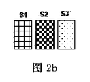
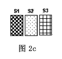
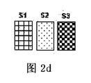
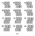
本発明の一つの実施例に基づき、図2a乃至図2dに示されたように、画素アレイにおける各画素ユニットは横縦比が2:3である異なる色の3つのサブ画素を含む。また、画素アレイは、同一の列に位置している2つの隣接する画素ユニットを有する複数の画素グループを含んでもよい。次の行の画素ユニットのサブ画素の左境界と上の行の画素ユニットのサブ画素の下境界の中間点が合わせられてもよい。又は上の行の画素ユニットのサブ画素の左境界と次の行の画素ユニットのサブ画素の上境界の中間点が合わせられてもよい。画素グループの各種配列方式は図5に示されている。 In accordance with one embodiment of the present invention, as shown in FIGS. 2a to 2d, each pixel unit in the pixel array includes three sub-pixels of different colors with an aspect ratio of 2: 3. The pixel array may also include a plurality of pixel groups having two adjacent pixel units located in the same column. The midpoint of the left boundary of the sub pixel of the pixel unit of the next row and the lower boundary of the sub pixel of the pixel unit of the upper row may be matched. Alternatively, the midpoint between the left boundary of the sub-pixel of the pixel unit in the upper row and the upper boundary of the sub-pixel of the pixel unit in the next row may be aligned. Various arrangements of pixel groups are shown in FIG.
図5に示されたように、画素グループは以下の各種配列方式における一種又は多種の方式により配列されてもよい。即ち、(1)上の行の画素ユニットのサブ画素は赤色サブ画素、青色サブ画素及び緑色サブ画素であり、次の行の画素ユニットのサブ画素は緑色サブ画素、赤色サブ画素及び青色サブ画素であり、且つ次の行の画素ユニットのサブ画素の左境界と上の行の画素ユニットのサブ画素の下境界の中間点は合わせられる。(2)上の行の画素ユニットのサブ画素は青色サブ画素、赤色サブ画素及び緑色サブ画素であり、次の行の画素ユニットのサブ画素は緑色サブ画素、青色サブ画素及び赤色サブ画素であり、且つ次の行の画素ユニットのサブ画素の左境界と上の行の画素ユニットのサブ画素の下境界の中間点は合わせられる。(3)上の行の画素ユニットのサブ画素は青色サブ画素、緑色サブ画素及び赤色サブ画素であり、次の行の画素ユニットのサブ画素は赤色サブ画素、青色サブ画素及び緑色サブ画素であり、且つ次の行の画素ユニットのサブ画素の左境界と上の行の画素ユニットのサブ画素の下境界の中間点は合わせられる。(4)上の行の画素ユニットのサブ画素は緑色サブ画素、青色サブ画素及び赤色サブ画素であり、次の行の画素ユニットのサブ画素は赤色サブ画素、緑色サブ画素及び青色サブ画素であり、且つ次の行の画素ユニットのサブ画素の左境界と上の行の画素ユニットのサブ画素の下境界の中間点は合わせられる。(5)上の行の画素ユニットのサブ画素は緑色サブ画素、赤色サブ画素及び青色サブ画素であり、次の行の画素ユニットのサブ画素は青色サブ画素、緑色サブ画素及び赤色サブ画素であり、且つ次の行の画素ユニットのサブ画素の左境界と上の行の画素ユニットのサブ画素の下境界の中間点は合わせられる。(6)上の行の画素ユニットのサブ画素は赤色サブ画素、緑色サブ画素及び青色サブ画素であり、次の行の画素ユニットのサブ画素は青色サブ画素、赤色サブ画素及び緑色サブ画素であり、且つ次の行の画素ユニットのサブ画素の左境界と上の行の画素ユニットのサブ画素の下境界の中間点は合わせられる。(7)上の行の画素ユニットのサブ画素は緑色サブ画素、赤色サブ画素及び青色サブ画素であり、次の行の画素ユニットのサブ画素は赤色サブ画素、青色サブ画素及び緑色サブ画素であり、且つ上の行の画素ユニットのサブ画素の左境界と次の行の画素ユニットのサブ画素の上境界の中間点は合わせられる。(8)上の行の画素ユニットのサブ画素は緑色サブ画素、青色サブ画素及び赤色サブ画素であり、次の行の画素ユニットのサブ画素は青色サブ画素、赤色サブ画素及び緑色サブ画素であり、且つ上の行の画素ユニットのサブ画素の左境界と次の行の画素ユニットのサブ画素の上境界の中間点は合わせられる。(9)上の行の画素ユニットのサブ画素は赤色サブ画素、青色サブ画素及び緑色サブ画素であり、次の行の画素ユニットのサブ画素は青色サブ画素、緑色サブ画素及び赤色サブ画素であり、且つ上の行の画素ユニットのサブ画素の左境界と次の行の画素ユニットのサブ画素の上境界の中間点は合わせられる。(10)上の行の画素ユニットのサブ画素は赤色サブ画素、緑色サブ画素及び青色サブ画素であり、次の行の画素ユニットのサブ画素は緑色サブ画素、青色サブ画素及び赤色サブ画素であり、且つ上の行の画素ユニットのサブ画素の左境界と次の行の画素ユニットのサブ画素の上境界の中間点は合わせられる。(11)上の行の画素ユニットのサブ画素は青色サブ画素、緑色サブ画素及び赤色サブ画素であり、次の行の画素ユニットのサブ画素は緑色サブ画素、赤色サブ画素及び青色サブ画素であり、且つ上の行の画素ユニットのサブ画素の左境界と次の行の画素ユニットのサブ画素の上境界の中間点は合わせられる。(12)上の行の画素ユニットのサブ画素は青色サブ画素、赤色サブ画素及び緑色サブ画素であり、次の行の画素ユニットのサブ画素は赤色サブ画素、緑色サブ画素及び青色サブ画素であり、且つ上の行の画素ユニットのサブ画素の左境界と次の行の画素ユニットのサブ画素の上境界の中間点は合わせられる。 As shown in FIG. 5, the pixel groups may be arranged by one or various methods in the following various arrangement methods. That is, (1) the sub-pixels of the pixel unit in the upper row are a red sub-pixel, a blue sub-pixel, and a green sub-pixel, and the sub-pixels of the pixel unit in the next row are a green sub-pixel, a red sub-pixel, and a blue sub-pixel. And the midpoint of the left boundary of the sub-pixel of the pixel unit in the next row and the lower boundary of the sub-pixel of the pixel unit in the upper row are matched. (2) The sub-pixels of the pixel unit in the upper row are a blue sub-pixel, a red sub-pixel, and a green sub-pixel, and the sub-pixels of the pixel unit in the next row are a green sub-pixel, a blue sub-pixel, and a red sub-pixel. In addition, the midpoint of the left boundary of the sub-pixel of the pixel unit in the next row and the lower boundary of the sub-pixel of the pixel unit in the upper row are matched. (3) The sub-pixels of the pixel unit in the upper row are a blue sub-pixel, a green sub-pixel, and a red sub-pixel, and the sub-pixels of the pixel unit in the next row are a red sub-pixel, a blue sub-pixel, and a green sub-pixel. In addition, the midpoint of the left boundary of the sub-pixel of the pixel unit in the next row and the lower boundary of the sub-pixel of the pixel unit in the upper row are matched. (4) The sub-pixels of the pixel unit in the upper row are a green sub-pixel, a blue sub-pixel, and a red sub-pixel, and the sub-pixels of the pixel unit in the next row are a red sub-pixel, a green sub-pixel, and a blue sub-pixel. In addition, the midpoint of the left boundary of the sub-pixel of the pixel unit in the next row and the lower boundary of the sub-pixel of the pixel unit in the upper row are matched. (5) The sub-pixels of the pixel unit in the upper row are a green sub-pixel, a red sub-pixel, and a blue sub-pixel, and the sub-pixels of the pixel unit in the next row are a blue sub-pixel, a green sub-pixel, and a red sub-pixel. In addition, the midpoint of the left boundary of the sub-pixel of the pixel unit in the next row and the lower boundary of the sub-pixel of the pixel unit in the upper row are matched. (6) The sub-pixels of the pixel unit in the upper row are a red sub-pixel, a green sub-pixel, and a blue sub-pixel, and the sub-pixels of the pixel unit in the next row are a blue sub-pixel, a red sub-pixel, and a green sub-pixel. In addition, the midpoint of the left boundary of the sub-pixel of the pixel unit in the next row and the lower boundary of the sub-pixel of the pixel unit in the upper row are matched. (7) The sub-pixels of the pixel unit in the upper row are a green sub-pixel, a red sub-pixel, and a blue sub-pixel, and the sub-pixels of the pixel unit in the next row are a red sub-pixel, a blue sub-pixel, and a green sub-pixel. And the midpoint between the left boundary of the sub-pixel of the pixel unit in the upper row and the upper boundary of the sub-pixel of the pixel unit in the next row is aligned. (8) The sub-pixels of the pixel unit in the upper row are a green sub-pixel, a blue sub-pixel, and a red sub-pixel, and the sub-pixels of the pixel unit in the next row are a blue sub-pixel, a red sub-pixel, and a green sub-pixel. And the midpoint between the left boundary of the sub-pixel of the pixel unit in the upper row and the upper boundary of the sub-pixel of the pixel unit in the next row is aligned. (9) The sub-pixels of the pixel unit in the upper row are a red sub-pixel, a blue sub-pixel, and a green sub-pixel, and the sub-pixels of the pixel unit in the next row are a blue sub-pixel, a green sub-pixel, and a red sub-pixel. And the midpoint between the left boundary of the sub-pixel of the pixel unit in the upper row and the upper boundary of the sub-pixel of the pixel unit in the next row is aligned. (10) The sub-pixels of the pixel unit in the upper row are a red sub-pixel, a green sub-pixel, and a blue sub-pixel, and the sub-pixels of the pixel unit in the next row are a green sub-pixel, a blue sub-pixel, and a red sub-pixel. And the midpoint between the left boundary of the sub-pixel of the pixel unit in the upper row and the upper boundary of the sub-pixel of the pixel unit in the next row is aligned. (11) The sub-pixels of the pixel unit in the upper row are a blue sub-pixel, a green sub-pixel, and a red sub-pixel, and the sub-pixels of the pixel unit in the next row are a green sub-pixel, a red sub-pixel, and a blue sub-pixel. And the midpoint between the left boundary of the sub-pixel of the pixel unit in the upper row and the upper boundary of the sub-pixel of the pixel unit in the next row is aligned. (12) The sub-pixels of the pixel unit in the upper row are a blue sub-pixel, a red sub-pixel, and a green sub-pixel, and the sub-pixels of the pixel unit in the next row are a red sub-pixel, a green sub-pixel, and a blue sub-pixel. And the midpoint between the left boundary of the sub-pixel of the pixel unit in the upper row and the upper boundary of the sub-pixel of the pixel unit in the next row is aligned.
以下に、図6及び図7を参照して、本発明の実施例に基づいた駆動方法を具体的に説明し、特に、各サブ画素の輝度値を算出する方法を具体的に説明する。 Hereinafter, a driving method based on an embodiment of the present invention will be described in detail with reference to FIGS. 6 and 7, and in particular, a method for calculating a luminance value of each sub-pixel will be specifically described.
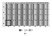
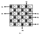
図6に示された例において、各サブ画素の横縦比は2:3であることに対して、区画された各理論的な画素ユニットの横縦比は1:1である。各理論的な画素ユニットは横方向で1.5個のサブ画素を覆うことに対し、横方向に隣接する2つごとの理論的な画素ユニットは3個のサブ画素、即ち1個の画素ユニットを覆う。これにより、本発明に基づいた駆動方法を用いて画素アレイを駆動するとき、横方向における解像度を二倍に高めるという表示効果は達成される。 In the example shown in FIG. 6, the aspect ratio of each sub-pixel is 2: 3, whereas the aspect ratio of each partitioned theoretical pixel unit is 1: 1. Each theoretical pixel unit covers 1.5 sub-pixels in the horizontal direction, whereas every two theoretical pixel units adjacent in the horizontal direction have 3 sub-pixels, that is, one pixel unit. Cover. Thereby, when the pixel array is driven using the driving method according to the present invention, the display effect of increasing the resolution in the horizontal direction by a factor of two is achieved.
図6に示されたように、隣接する二行の間に、サブ画素の境界はアラインされる。しかしながら、本発明はこれに限らず、例えば図5に示された各種の配列方式に基づきサブ画素を配置してもよい。 As shown in FIG. 6, the boundary between subpixels is aligned between two adjacent rows. However, the present invention is not limited to this. For example, the sub-pixels may be arranged based on various arrangement methods shown in FIG.
また、図6の例において、各赤色サブ画素がチェッカーボードの形式で強調的に示されたことに対して、図の混乱を避けるために、横方向における2つの隣接する赤色サブ画素の間に、青色及び緑色サブ画素が空白の方式で示された。 Also, in the example of FIG. 6, each red sub-pixel is highlighted in the form of a checkerboard, whereas in order to avoid confusion in the figure, between two adjacent red sub-pixels in the horizontal direction. The blue and green sub-pixels are shown in a blank manner.
先ず、所望の解像度に基づき、表示される画像を、表示される画像の対応的な領域における複数の色分量を含む複数の理論的な画素ユニットに区画する。言い換えれば、所望の解像度に基づき、表示される画像により、各理論的な画素ユニットにおける各異なる色成分の輝度値を算出する(例えば、赤色成分の輝度値、緑色成分の輝度値及び青色成分の輝度値)。 First, based on a desired resolution, a displayed image is divided into a plurality of theoretical pixel units including a plurality of color components in a corresponding region of the displayed image. In other words, based on the desired resolution, the luminance value of each different color component in each theoretical pixel unit is calculated from the displayed image (for example, the luminance value of the red component, the luminance value of the green component, and the blue component) Brightness value).
その後、区画された各理論的な画素ユニットの色分量に基づき、各画素ユニットの各サブ画素の輝度値を算出する。以下に、赤色サブ画素を例として、各サブ画素の輝度値を算出するための方法を説明する。 Thereafter, the luminance value of each sub-pixel of each pixel unit is calculated based on the color amount of each divided theoretical pixel unit. Hereinafter, a method for calculating the luminance value of each sub-pixel will be described using the red sub-pixel as an example.
先ず、算出されるサブ画素(例えば、赤色サブ画素F3)に、該サブ画素の中心を中心とし、該サブ画素と同行又は同列であり且つ同じ色を有する隣接的なサブ画素(例えば、赤色サブ画素F3の上部の赤色サブ画素F2)の中心と該サブ画素の中心とのラインの中間点を夫々4つの頂点とするひし形サンプリング領域を区画する。図6において、赤色サブ画素F3のひし形サンプリング領域の4つの頂点が小さな丸で例示的に示された。 First, the calculated sub-pixel (for example, the red sub-pixel F3) has an adjacent sub-pixel (for example, the red sub-pixel F3) that is centered on the center of the sub-pixel, is in the same row or column as the sub-pixel, and has the same color. A rhombus sampling region having four vertexes at the midpoint of the line between the center of the red subpixel F2) above the pixel F3 and the center of the subpixel is defined. In FIG. 6, the four vertices of the diamond sampling region of the red sub-pixel F3 are exemplarily shown by small circles.
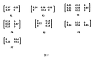
次に、各理論的な画素ユニットと該サブ画素のひし形サンプリング領域との重なり面積と、該ひし形サンプリング領域の面積との比を、該サブ画素のひし形サンプリング領域に対する該理論的な画素ユニットの面積割合として算出する。例えば、赤色サブ画素F3のひし形サンプリング領域と7つの理論的な画素ユニットとは、夫々、赤色サブ画素F3の左上方、左下方、上方、下方、左側及び右側の理論的な画素ユニット及び赤色サブ画素F3を覆う理論的な画素ユニットである重なり部分を有する。図7において、赤色サブ画素F3のひし形サンプリング領域に対する各理論的な画素ユニットの面積割合は、マトリックスの形式で示された。同じ方式で、図7に示されたように、各赤色サブ画素F1乃至F7の面積割合マトリックスが算出される。注意すべきことは、サブ画素は画素アレイの縁部又は角部に位置するとき、該サブ画素のひし形サンプリング領域は完全なひし形ではなく、ひし形サンプリング領域に対する理論的な画素ユニットの面積割合を算出するときに、ひし形サンプリング領域の(完全なひし形の面積ではなく)実際の面積で算出すべきことである。また、図7に示された各面積割合マトリックスにおいて、算出された各面積割合に四捨五入を行う。 Next, the ratio of the overlap area between each theoretical pixel unit and the diamond sampling region of the subpixel and the area of the diamond sampling region is determined by calculating the area of the theoretical pixel unit with respect to the diamond sampling region of the subpixel. Calculate as a percentage. For example, the diamond sampling region of the red sub-pixel F3 and the seven theoretical pixel units are respectively the upper left, lower left, upper, lower, left and right theoretical pixel units and the red sub-pixel of the red sub-pixel F3. It has an overlapping part which is a theoretical pixel unit covering the pixel F3. In FIG. 7, the area ratio of each theoretical pixel unit to the diamond sampling region of the red sub-pixel F3 is shown in the form of a matrix. In the same manner, as shown in FIG. 7, the area ratio matrix of each red sub-pixel F1 to F7 is calculated. It should be noted that when the subpixel is located at the edge or corner of the pixel array, the diamond sampling area of the subpixel is not a perfect rhombus, and the area ratio of the theoretical pixel unit to the diamond sampling area is calculated. When calculating the actual area of the diamond sampling area (not the area of the complete diamond). Further, in each area ratio matrix shown in FIG. 7, the calculated area ratio is rounded off.
その後、該サブ画素のひし形サンプリング領域に対する各理論的な画素ユニットの面積割合に、該サブ画素と同じ色の該理論的な画素ユニットの色分量を掛けて得られる各積の和を該サブ画素の輝度値とする。例えば、赤色サブ画素F3の輝度を算出するとき、赤色サブ画素F3の左上方の理論的な画素ユニットの赤色分量(即ち、赤色成分の輝度値)に面積割合0.01を掛け、赤色サブ画素F3の上方の理論的な画素ユニットの赤色分量に面積割合0.12を掛け、赤色サブ画素F3の左側の理論的な画素ユニットの赤色分量に面積割合0.21を掛け、赤色サブ画素F3の右側の理論的な画素ユニットの赤色分量に面積割合0.05を掛け、赤色サブ画素F3の左下方の理論的な画素ユニットの赤色分量に面積割合0.01を掛け、赤色サブ画素F3の下方の理論的な画素ユニットの赤色分量に面積割合0.12を掛け、且つ、赤色サブ画素F3を覆う理論的な画素ユニットの赤色分量に面積割合0.48を掛けることにより算出された各積の和を、赤色サブ画素F3の輝度値とする。 Thereafter, the sum of each product obtained by multiplying the area ratio of each theoretical pixel unit with respect to the diamond sampling region of the subpixel by the amount of color of the theoretical pixel unit having the same color as the subpixel is obtained. Luminance value. For example, when calculating the luminance of the red sub-pixel F3, the red sub-pixel F3 is multiplied by the area ratio 0.01 to the red amount (that is, the luminance value of the red component) of the theoretical pixel unit at the upper left of the red sub-pixel F3. The red amount of the theoretical pixel unit above F3 is multiplied by an area ratio of 0.12, the red quantity of the theoretical pixel unit on the left side of the red subpixel F3 is multiplied by an area ratio of 0.21, and the red subpixel F3's Multiply the red amount of the theoretical pixel unit on the right by the area ratio 0.05, multiply the red amount of the theoretical pixel unit at the lower left of the red sub-pixel F3 by the area ratio 0.01, and below the red sub-pixel F3. The product of each product calculated by multiplying the red amount of the theoretical pixel unit by an area ratio of 0.12 and multiplying the red quantity of the theoretical pixel unit covering the red sub-pixel F3 by an area ratio of 0.48. And the luminance value of the red sub-pixel F3.
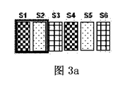
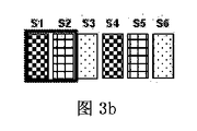
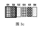
図3a乃至図3cは、本発明のもう一つの実施例に基づいた画素アレイにおける画素ユニットの概略図である。図3a乃至図3cに示されたように、各サブ画素の横縦比は1:2である。各理論的な画素ユニットは横方向で2個のサブ画素を覆うことに対し、横方向に隣接する3つごとの理論的な画素ユニットは6個のサブ画素、即ち2個の画素ユニットを覆う。これにより、本発明に基づいた駆動方法を用いて画素アレイを駆動するとき、横方向における解像度を1.5倍に高めるという表示効果は達成される。 3a to 3c are schematic views of pixel units in a pixel array according to another embodiment of the present invention. As shown in FIGS. 3a to 3c, the aspect ratio of each sub-pixel is 1: 2. Each theoretical pixel unit covers two sub-pixels in the horizontal direction, whereas every third theoretical pixel unit adjacent in the horizontal direction covers six sub-pixels, ie two pixel units. . Thus, when the pixel array is driven using the driving method according to the present invention, the display effect of increasing the resolution in the horizontal direction by 1.5 times is achieved.
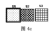
図4a乃至図4fは、本発明の他の実施例に基づいた画素アレイにおける画素ユニットの概略図である。図4a乃至図4fに示されたように、各サブ画素の横縦比は1:1である。各理論的な画素ユニットは横方向で1個のサブ画素を覆うことに対し、横方向に隣接する3つごとの理論的な画素ユニットは3個のサブ画素、即ち1個の画素ユニットを覆う。これにより、本発明に基づいた駆動方法を用いて画素アレイを駆動するとき、横方向における解像度を3倍に高めるという表示効果は達成される。 4a to 4f are schematic views of pixel units in a pixel array according to another embodiment of the present invention. As shown in FIGS. 4a to 4f, the aspect ratio of each sub-pixel is 1: 1. Each theoretical pixel unit covers one sub-pixel in the horizontal direction, whereas every third theoretical pixel unit adjacent in the horizontal direction covers three sub-pixels, that is, one pixel unit. . As a result, when the pixel array is driven using the driving method according to the present invention, the display effect of increasing the resolution in the horizontal direction by three times is achieved.
前文において、3つの色のサブ画素を含む画素アレイが説明されたにもかかわらず、当業者に理解できるように、画素アレイは4つの色のサブ画素を含んでもよい(例えば、赤色、緑色、青色及び白色)。 In the preceding sentence, although a pixel array including three color sub-pixels has been described, the pixel array may include four color sub-pixels (eg, red, green, Blue and white).
理解できるように、上記の実施形態は、本発明の原理を説明するために用いられる例示的な実施形態に過ぎず、本発明はこれに限らない。本分野における通常の技術者は、本発明の精神及び実質に背かない状況で、様々な変型及び改善をすることができる。これらの変型及び改善も本発明の保護範囲と見なす。 As can be appreciated, the above embodiments are merely exemplary embodiments used to describe the principles of the invention, and the invention is not limited thereto. Those skilled in the art can make various modifications and improvements without departing from the spirit and substance of the present invention. These variations and improvements are also considered as the protection scope of the present invention.
Claims (6)
表示される画像を複数の色分量を有する複数の理論的な画素ユニットに区画するステップと、
各サブ画素に、該サブ画素の中心を中心とし、該サブ画素と同行又は同列であり且つ同じ色を有する隣接的なサブ画素の中心と該サブ画素の中心とのラインの中間点を夫々4つの頂点とするひし形サンプリング領域を区画するサブステップと、
各理論的な画素ユニットと該サブ画素のひし形サンプリング領域との重なり面積と、該ひし形サンプリング領域の面積との比を、該サブ画素のひし形サンプリング領域に対する該理論的な画素ユニットの面積割合として算出するサブステップと、
該サブ画素のひし形サンプリング領域に対する各理論的な画素ユニットの面積割合に、該サブ画素と同じ色の該理論的な画素ユニットの色分量を掛けて得られる各積の和を該サブ画素の輝度値とするサブステップとを有する、
区画された各理論的な画素ユニットの色分量に基づき、各画素ユニットの各サブ画素の輝度値を算出するステップとを含む、画素アレイの駆動方法。 A driving method of a pixel array including a plurality of pixel units having a plurality of sub-pixels of different colors having an aspect ratio of 1: 2 to 1: 1,
Partitioning a displayed image into a plurality of theoretical pixel units having a plurality of color quantities;
Each subpixel is centered on the center of the subpixel, and the middle point of the line between the center of the adjacent subpixel and the center of the subpixel that is in the same row or in the same column as the subpixel and has the same color. A sub-step that defines a diamond sampling region with two vertices;
The ratio of the overlapping area of each theoretical pixel unit and the diamond sampling area of the sub-pixel and the area of the diamond sampling area is calculated as the area ratio of the theoretical pixel unit to the diamond sampling area of the sub-pixel. Substeps to
The luminance of each subpixel is obtained by multiplying the area ratio of each theoretical pixel unit with respect to the diamond sampling region of the subpixel by the amount of color of the theoretical pixel unit having the same color as the subpixel. A sub-step as a value,
And a step of calculating a luminance value of each sub-pixel of each pixel unit based on a color amount of each theoretical pixel unit partitioned.
上の行の画素ユニットのサブ画素が赤色サブ画素、青色サブ画素及び緑色サブ画素であり、次の行の画素ユニットのサブ画素が緑色サブ画素、赤色サブ画素及び青色サブ画素であり、且つ次の行の画素ユニットのサブ画素の左境界と上の行の画素ユニットのサブ画素の下境界の中間点が合わせられ、
上の行の画素ユニットのサブ画素が青色サブ画素、赤色サブ画素及び緑色サブ画素であり、次の行の画素ユニットのサブ画素が緑色サブ画素、青色サブ画素及び赤色サブ画素であり、且つ次の行の画素ユニットのサブ画素の左境界と上の行の画素ユニットのサブ画素の下境界の中間点が合わせられ、
上の行の画素ユニットのサブ画素が青色サブ画素、緑色サブ画素及び赤色サブ画素であり、次の行の画素ユニットのサブ画素が赤色サブ画素、青色サブ画素及び緑色サブ画素であり、且つ次の行の画素ユニットのサブ画素の左境界と上の行の画素ユニットのサブ画素の下境界の中間点が合わせられ、
上の行の画素ユニットのサブ画素が緑色サブ画素、青色サブ画素及び赤色サブ画素であり、次の行の画素ユニットのサブ画素が赤色サブ画素、緑色サブ画素及び青色サブ画素であり、且つ次の行の画素ユニットのサブ画素の左境界と上の行の画素ユニットのサブ画素の下境界の中間点が合わせられ、
上の行の画素ユニットのサブ画素が緑色サブ画素、赤色サブ画素及び青色サブ画素であり、次の行の画素ユニットのサブ画素が青色サブ画素、緑色サブ画素及び赤色サブ画素であり、且つ次の行の画素ユニットのサブ画素の左境界と上の行の画素ユニットのサブ画素の下境界の中間点が合わせられ、
上の行の画素ユニットのサブ画素が赤色サブ画素、緑色サブ画素及び青色サブ画素であり、次の行の画素ユニットのサブ画素が青色サブ画素、赤色サブ画素及び緑色サブ画素であり、且つ次の行の画素ユニットのサブ画素の左境界と上の行の画素ユニットのサブ画素の下境界の中間点が合わせられ、
上の行の画素ユニットのサブ画素が緑色サブ画素、赤色サブ画素及び青色サブ画素であり、次の行の画素ユニットのサブ画素が赤色サブ画素、青色サブ画素及び緑色サブ画素であり、且つ上の行の画素ユニットのサブ画素の左境界と次の行の画素ユニットのサブ画素の上境界の中間点が合わせられ、
上の行の画素ユニットのサブ画素が緑色サブ画素、青色サブ画素及び赤色サブ画素であり、次の行の画素ユニットのサブ画素が青色サブ画素、赤色サブ画素及び緑色サブ画素であり、且つ上の行の画素ユニットのサブ画素の左境界と次の行の画素ユニットのサブ画素の上境界の中間点が合わせられ、
上の行の画素ユニットのサブ画素が赤色サブ画素、青色サブ画素及び緑色サブ画素であり、次の行の画素ユニットのサブ画素が青色サブ画素、緑色サブ画素及び赤色サブ画素であり、且つ上の行の画素ユニットのサブ画素の左境界と次の行の画素ユニットのサブ画素の上境界の中間点が合わせられ、
上の行の画素ユニットのサブ画素が赤色サブ画素、緑色サブ画素及び青色サブ画素であり、次の行の画素ユニットのサブ画素が緑色サブ画素、青色サブ画素及び赤色サブ画素であり、且つ上の行の画素ユニットのサブ画素の左境界と次の行の画素ユニットのサブ画素の上境界の中間点が合わせられ、
上の行の画素ユニットのサブ画素が青色サブ画素、緑色サブ画素及び赤色サブ画素であり、次の行の画素ユニットのサブ画素が緑色サブ画素、赤色サブ画素及び青色サブ画素であり、且つ上の行の画素ユニットのサブ画素の左境界と次の行の画素ユニットのサブ画素の上境界の中間点が合わせられ、
上の行の画素ユニットのサブ画素が青色サブ画素、赤色サブ画素及び緑色サブ画素であり、次の行の画素ユニットのサブ画素が赤色サブ画素、緑色サブ画素及び青色サブ画素であり、且つ上の行の画素ユニットのサブ画素の左境界と次の行の画素ユニットのサブ画素の上境界の中間点が合わせられるような、各種配列方式における一種又は多種の方式により配列される、請求項3に記載の画素アレイの駆動方法。 The pixel groups are as follows:
The sub-pixels of the pixel unit in the upper row are a red sub-pixel, a blue sub-pixel, and a green sub-pixel, the sub-pixels of the pixel unit in the next row are a green sub-pixel, a red sub-pixel, and a blue sub-pixel, and The middle point of the left boundary of the sub-pixel of the pixel unit in the row and the lower boundary of the sub-pixel of the pixel unit in the upper row are combined,
The sub-pixels of the pixel unit in the upper row are a blue sub-pixel, a red sub-pixel, and a green sub-pixel, the sub-pixels of the pixel unit in the next row are a green sub-pixel, a blue sub-pixel, and a red sub-pixel, and The middle point of the left boundary of the sub-pixel of the pixel unit in the row and the lower boundary of the sub-pixel of the pixel unit in the upper row are combined,
The sub-pixels of the pixel unit in the upper row are the blue sub-pixel, the green sub-pixel, and the red sub-pixel, the sub-pixels of the pixel unit in the next row are the red sub-pixel, the blue sub-pixel, and the green sub-pixel, and The middle point of the left boundary of the sub-pixel of the pixel unit in the row and the lower boundary of the sub-pixel of the pixel unit in the upper row are combined,
The sub-pixels of the pixel unit in the upper row are green sub-pixels, blue sub-pixels and red sub-pixels, the sub-pixels of the pixel unit in the next row are red sub-pixels, green sub-pixels and blue sub-pixels, and The middle point of the left boundary of the sub-pixel of the pixel unit in the row and the lower boundary of the sub-pixel of the pixel unit in the upper row are combined,
The sub-pixels of the pixel unit in the upper row are green sub-pixels, red sub-pixels and blue sub-pixels, the sub-pixels of the pixel unit in the next row are blue sub-pixels, green sub-pixels and red sub-pixels, and The middle point of the left boundary of the sub-pixel of the pixel unit in the row and the lower boundary of the sub-pixel of the pixel unit in the upper row are combined,
The sub-pixels of the pixel unit in the upper row are a red sub-pixel, a green sub-pixel, and a blue sub-pixel, the sub-pixels of the pixel unit in the next row are a blue sub-pixel, a red sub-pixel, and a green sub-pixel, and The middle point of the left boundary of the sub-pixel of the pixel unit in the row and the lower boundary of the sub-pixel of the pixel unit in the upper row are combined,
The sub-pixels of the pixel unit in the upper row are a green sub-pixel, a red sub-pixel, and a blue sub-pixel, the sub-pixels of the pixel unit in the next row are a red sub-pixel, a blue sub-pixel, and a green sub-pixel, and the upper The midpoint of the left boundary of the sub-pixel of the pixel unit in the next row and the upper boundary of the sub-pixel of the pixel unit in the next row is matched,
The sub-pixels of the pixel unit in the upper row are the green sub-pixel, the blue sub-pixel, and the red sub-pixel, the sub-pixels of the pixel unit in the next row are the blue sub-pixel, the red sub-pixel, and the green sub-pixel, and the upper The midpoint of the left boundary of the sub-pixel of the pixel unit in the next row and the upper boundary of the sub-pixel of the pixel unit in the next row is matched,
The sub-pixels of the pixel unit in the upper row are the red sub-pixel, the blue sub-pixel, and the green sub-pixel, the sub-pixels of the pixel unit in the next row are the blue sub-pixel, the green sub-pixel, and the red sub-pixel, and the upper The midpoint of the left boundary of the sub-pixel of the pixel unit in the next row and the upper boundary of the sub-pixel of the pixel unit in the next row is matched,
The sub-pixels of the pixel unit in the upper row are the red sub-pixel, the green sub-pixel, and the blue sub-pixel, the sub-pixels of the pixel unit in the next row are the green sub-pixel, the blue sub-pixel, and the red sub-pixel, and the upper The midpoint of the left boundary of the sub-pixel of the pixel unit in the next row and the upper boundary of the sub-pixel of the pixel unit in the next row is matched,
The sub-pixels of the pixel unit in the upper row are a blue sub-pixel, a green sub-pixel, and a red sub-pixel, the sub-pixels of the pixel unit in the next row are a green sub-pixel, a red sub-pixel, and a blue sub-pixel, and the upper The midpoint of the left boundary of the sub-pixel of the pixel unit in the next row and the upper boundary of the sub-pixel of the pixel unit in the next row is matched,
The sub-pixels of the pixel unit in the upper row are a blue sub-pixel, a red sub-pixel, and a green sub-pixel, the sub-pixels of the pixel unit in the next row are a red sub-pixel, a green sub-pixel, and a blue sub-pixel, and the upper 4. The arrangement is performed by one or various methods in various arrangement methods such that the left boundary of the sub-pixel of the pixel unit in the next row and the middle point of the upper boundary of the sub-pixel of the pixel unit in the next row are matched. A driving method of the pixel array described in 1.
Applications Claiming Priority (3)
| Application Number | Priority Date | Filing Date | Title |
|---|---|---|---|
| CN201410602640.X | 2014-10-31 | ||
| CN201410602640.XA CN104299561B (en) | 2014-10-31 | 2014-10-31 | Driving method for pixel array |
| PCT/CN2015/076268 WO2016065849A1 (en) | 2014-10-31 | 2015-04-10 | Drive method for pixel array |
Publications (2)
| Publication Number | Publication Date |
|---|---|
| JP2017536583A true JP2017536583A (en) | 2017-12-07 |
| JP2017536583A5 JP2017536583A5 (en) | 2018-03-29 |
Family
ID=52319263
Family Applications (1)
| Application Number | Title | Priority Date | Filing Date |
|---|---|---|---|
| JP2017542239A Pending JP2017536583A (en) | 2014-10-31 | 2015-04-10 | Driving method of pixel array |
Country Status (6)
| Country | Link |
|---|---|
| US (1) | US10249259B2 (en) |
| EP (1) | EP3214615A4 (en) |
| JP (1) | JP2017536583A (en) |
| KR (1) | KR101708139B1 (en) |
| CN (1) | CN104299561B (en) |
| WO (1) | WO2016065849A1 (en) |
Families Citing this family (16)
| Publication number | Priority date | Publication date | Assignee | Title |
|---|---|---|---|---|
| CN104036710B (en) * | 2014-02-21 | 2016-05-04 | 北京京东方光电科技有限公司 | Pel array and driving method thereof, display floater and display unit |
| CN104299561B (en) * | 2014-10-31 | 2017-01-18 | 京东方科技集团股份有限公司 | Driving method for pixel array |
| CN104599626B (en) | 2015-03-02 | 2017-03-01 | 京东方科技集团股份有限公司 | Display drive method and device, the generation method of sample region and device |
| CN104766548A (en) * | 2015-03-17 | 2015-07-08 | 京东方科技集团股份有限公司 | Display device and display method thereof |
| CN104680966B (en) * | 2015-03-19 | 2017-11-14 | 京东方科技集团股份有限公司 | The driving method and its drive device of a kind of display device |
| CN104681001A (en) | 2015-03-23 | 2015-06-03 | 京东方科技集团股份有限公司 | Display driving method and display driving device |
| CN104793341B (en) * | 2015-05-12 | 2018-01-12 | 京东方科技集团股份有限公司 | A kind of display drive method and device |
| CN104978920B (en) * | 2015-07-24 | 2018-10-16 | 京东方科技集团股份有限公司 | Pel array, display device and its display methods |
| CN104992688B (en) * | 2015-08-05 | 2018-01-09 | 京东方科技集团股份有限公司 | Pel array, display device and its driving method and drive device |
| CN106023818B (en) * | 2016-05-18 | 2019-09-17 | 京东方科技集团股份有限公司 | A kind of driving method of dot structure, display panel and dot structure |
| CN108807460B (en) * | 2017-04-28 | 2019-08-23 | 昆山国显光电有限公司 | Dot structure driving method |
| CN109427265B (en) * | 2017-08-31 | 2020-10-16 | 昆山国显光电有限公司 | Pixel driving method |
| WO2019042072A1 (en) | 2017-08-31 | 2019-03-07 | 昆山国显光电有限公司 | Pixel structure, oled display device, and driving method |
| CN108831376A (en) * | 2018-07-27 | 2018-11-16 | 京东方科技集团股份有限公司 | Dot structure and its driving method, display base plate and display device |
| CN112447147B (en) * | 2019-08-30 | 2022-09-02 | 合肥鑫晟光电科技有限公司 | Liquid crystal display panel, display device and brightness conversion method thereof |
| CN110992867B (en) * | 2019-12-18 | 2023-02-28 | 京东方科技集团股份有限公司 | Image processing method and display device |
Citations (6)
| Publication number | Priority date | Publication date | Assignee | Title |
|---|---|---|---|---|
| JP2004530924A (en) * | 2001-05-09 | 2004-10-07 | クレアーボヤント ラボラトリーズ、インコーポレイテッド | Conversion from one subpixel format data to another subpixel data format |
| US20100045695A1 (en) * | 2007-04-20 | 2010-02-25 | Candice Hellen Brown Elliott | Subpixel rendering area resample functions for display device |
| CN103777393A (en) * | 2013-12-16 | 2014-05-07 | 北京京东方光电科技有限公司 | Display panel, display method of display panel, and display device |
| CN103886825A (en) * | 2014-02-21 | 2014-06-25 | 北京京东方光电科技有限公司 | Pixel array driving method and display device |
| CN104036710A (en) * | 2014-02-21 | 2014-09-10 | 北京京东方光电科技有限公司 | Pixel array, driving method for pixel array, display panel and display device |
| CN104112763A (en) * | 2014-06-30 | 2014-10-22 | 京东方科技集团股份有限公司 | Pixel arrangement structure, display device and display method thereof |
Family Cites Families (13)
| Publication number | Priority date | Publication date | Assignee | Title |
|---|---|---|---|---|
| US20080079748A1 (en) * | 1997-09-13 | 2008-04-03 | Phan Gia C | Image sensor and image data processing system |
| US6608632B2 (en) * | 2000-06-12 | 2003-08-19 | Sharp Laboratories Of America, Inc. | Methods and systems for improving display resolution in images using sub-pixel sampling and visual error filtering |
| TW493782U (en) | 2001-04-03 | 2002-07-01 | Giantplus Technology Co Ltd | Pixel driving module of liquid crystal display |
| JP2004152737A (en) | 2002-11-01 | 2004-05-27 | Matsushita Electric Ind Co Ltd | Plasma display panel and plasma display panel display device |
| US20060158466A1 (en) | 2005-01-18 | 2006-07-20 | Sitronix Technology Corp. | Shared pixels rendering display |
| US20060170712A1 (en) * | 2005-02-01 | 2006-08-03 | Eastman Kodak Company | Color display device with enhanced pixel pattern |
| JP4879084B2 (en) * | 2007-05-10 | 2012-02-15 | 三菱電機株式会社 | Image processing device |
| US8896505B2 (en) | 2009-06-12 | 2014-11-25 | Global Oled Technology Llc | Display with pixel arrangement |
| CN103714751B (en) * | 2013-12-30 | 2016-06-22 | 北京京东方光电科技有限公司 | Pel array and driving method, display floater and display device |
| CN103824520B (en) * | 2014-01-26 | 2016-08-31 | 北京京东方光电科技有限公司 | Pel array and driving method, display floater and display device |
| CN103886808B (en) * | 2014-02-21 | 2016-02-24 | 北京京东方光电科技有限公司 | Display packing and display device |
| CN103903549B (en) | 2014-03-25 | 2016-08-17 | 京东方科技集团股份有限公司 | Display packing |
| CN104299561B (en) | 2014-10-31 | 2017-01-18 | 京东方科技集团股份有限公司 | Driving method for pixel array |
-
2014
- 2014-10-31 CN CN201410602640.XA patent/CN104299561B/en active Active
-
2015
- 2015-04-10 EP EP15763180.5A patent/EP3214615A4/en not_active Ceased
- 2015-04-10 WO PCT/CN2015/076268 patent/WO2016065849A1/en active Application Filing
- 2015-04-10 US US14/778,694 patent/US10249259B2/en active Active
- 2015-04-10 KR KR1020157025878A patent/KR101708139B1/en active IP Right Grant
- 2015-04-10 JP JP2017542239A patent/JP2017536583A/en active Pending
Patent Citations (6)
| Publication number | Priority date | Publication date | Assignee | Title |
|---|---|---|---|---|
| JP2004530924A (en) * | 2001-05-09 | 2004-10-07 | クレアーボヤント ラボラトリーズ、インコーポレイテッド | Conversion from one subpixel format data to another subpixel data format |
| US20100045695A1 (en) * | 2007-04-20 | 2010-02-25 | Candice Hellen Brown Elliott | Subpixel rendering area resample functions for display device |
| CN103777393A (en) * | 2013-12-16 | 2014-05-07 | 北京京东方光电科技有限公司 | Display panel, display method of display panel, and display device |
| CN103886825A (en) * | 2014-02-21 | 2014-06-25 | 北京京东方光电科技有限公司 | Pixel array driving method and display device |
| CN104036710A (en) * | 2014-02-21 | 2014-09-10 | 北京京东方光电科技有限公司 | Pixel array, driving method for pixel array, display panel and display device |
| CN104112763A (en) * | 2014-06-30 | 2014-10-22 | 京东方科技集团股份有限公司 | Pixel arrangement structure, display device and display method thereof |
Also Published As
| Publication number | Publication date |
|---|---|
| EP3214615A1 (en) | 2017-09-06 |
| CN104299561A (en) | 2015-01-21 |
| KR101708139B1 (en) | 2017-02-17 |
| WO2016065849A1 (en) | 2016-05-06 |
| CN104299561B (en) | 2017-01-18 |
| KR20160065772A (en) | 2016-06-09 |
| US10249259B2 (en) | 2019-04-02 |
| US20160329026A1 (en) | 2016-11-10 |
| EP3214615A4 (en) | 2018-06-27 |
Similar Documents
| Publication | Publication Date | Title |
|---|---|---|
| JP2017536583A (en) | Driving method of pixel array | |
| US9824620B2 (en) | Driving method for pixel array and display device | |
| JP6802066B2 (en) | Display drive method and device, sampling area generation method and device | |
| WO2016150076A1 (en) | Pixel array, display drive method, display drive apparatus, and display apparatus | |
| CN103927946B (en) | Display packing | |
| US9601082B2 (en) | Display substrate and driving method thereof and display device | |
| CN103778882B (en) | Pel array and driving method, display panel and display device | |
| US9734795B2 (en) | Pixel array and driving method thereof, display panel and display device | |
| JP2017536583A5 (en) | ||
| US9508296B2 (en) | Driving method of pixel array, driving module of pixel array and display device | |
| US9892696B2 (en) | Display panel having a plurality of pixels driven in a time-sharing manner, display method thereof and display device | |
| CN103903549A (en) | Display method | |
| KR101970088B1 (en) | Display screen and method of driving the same | |
| CN103714751A (en) | Pixel array, driving method of pixel array, display panel and display device | |
| US20150301239A1 (en) | Pixel array | |
| US10573247B2 (en) | Pixel array, display driving device having sub-pixel groups offsetting in column and driving method thereof, and display device | |
| JP2018517915A (en) | Display driving method and display driving apparatus | |
| CN105185247A (en) | Display panel, display device and display method | |
| JP2015018239A (en) | Pixel array | |
| CN105185270A (en) | Display panel, display device and display method | |
| US9361839B2 (en) | Double-vision display device and method for driving the same |
Legal Events
| Date | Code | Title | Description |
|---|---|---|---|
| A521 | Request for written amendment filed |
Free format text: JAPANESE INTERMEDIATE CODE: A523 Effective date: 20180213 |
|
| A621 | Written request for application examination |
Free format text: JAPANESE INTERMEDIATE CODE: A621 Effective date: 20180213 |
|
| A977 | Report on retrieval |
Free format text: JAPANESE INTERMEDIATE CODE: A971007 Effective date: 20190123 |
|
| A131 | Notification of reasons for refusal |
Free format text: JAPANESE INTERMEDIATE CODE: A131 Effective date: 20190208 |
|
| A521 | Request for written amendment filed |
Free format text: JAPANESE INTERMEDIATE CODE: A523 Effective date: 20190508 |
|
| A02 | Decision of refusal |
Free format text: JAPANESE INTERMEDIATE CODE: A02 Effective date: 20190805 |
|
| A521 | Request for written amendment filed |
Free format text: JAPANESE INTERMEDIATE CODE: A523 Effective date: 20191203 |
|
| C60 | Trial request (containing other claim documents, opposition documents) |
Free format text: JAPANESE INTERMEDIATE CODE: C60 Effective date: 20191203 |
|
| A911 | Transfer to examiner for re-examination before appeal (zenchi) |
Free format text: JAPANESE INTERMEDIATE CODE: A911 Effective date: 20191210 |
|
| C21 | Notice of transfer of a case for reconsideration by examiners before appeal proceedings |
Free format text: JAPANESE INTERMEDIATE CODE: C21 Effective date: 20191216 |
|
| A912 | Re-examination (zenchi) completed and case transferred to appeal board |
Free format text: JAPANESE INTERMEDIATE CODE: A912 Effective date: 20200117 |
|
| C211 | Notice of termination of reconsideration by examiners before appeal proceedings |
Free format text: JAPANESE INTERMEDIATE CODE: C211 Effective date: 20200127 |
|
| C22 | Notice of designation (change) of administrative judge |
Free format text: JAPANESE INTERMEDIATE CODE: C22 Effective date: 20200713 |
|
| C23 | Notice of termination of proceedings |
Free format text: JAPANESE INTERMEDIATE CODE: C23 Effective date: 20200831 |
|
| C03 | Trial/appeal decision taken |
Free format text: JAPANESE INTERMEDIATE CODE: C03 Effective date: 20201005 |
|
| C30A | Notification sent |
Free format text: JAPANESE INTERMEDIATE CODE: C3012 Effective date: 20201005 |
