JP2017535495A - Radius conveyor with magnetic bearings - Google Patents
Radius conveyor with magnetic bearings Download PDFInfo
- Publication number
- JP2017535495A JP2017535495A JP2017519543A JP2017519543A JP2017535495A JP 2017535495 A JP2017535495 A JP 2017535495A JP 2017519543 A JP2017519543 A JP 2017519543A JP 2017519543 A JP2017519543 A JP 2017519543A JP 2017535495 A JP2017535495 A JP 2017535495A
- Authority
- JP
- Japan
- Prior art keywords
- electrically conductive
- conveyor
- conveyor belt
- magnetic field
- side edge
- Prior art date
- Legal status (The legal status is an assumption and is not a legal conclusion. Google has not performed a legal analysis and makes no representation as to the accuracy of the status listed.)
- Pending
Links
Images


Classifications
-
- B—PERFORMING OPERATIONS; TRANSPORTING
- B65—CONVEYING; PACKING; STORING; HANDLING THIN OR FILAMENTARY MATERIAL
- B65G—TRANSPORT OR STORAGE DEVICES, e.g. CONVEYORS FOR LOADING OR TIPPING, SHOP CONVEYOR SYSTEMS OR PNEUMATIC TUBE CONVEYORS
- B65G21/00—Supporting or protective framework or housings for endless load-carriers or traction elements of belt or chain conveyors
- B65G21/20—Means incorporated in, or attached to, framework or housings for guiding load-carriers, traction elements or loads supported on moving surfaces
- B65G21/2009—Magnetic retaining means
-
- B—PERFORMING OPERATIONS; TRANSPORTING
- B65—CONVEYING; PACKING; STORING; HANDLING THIN OR FILAMENTARY MATERIAL
- B65G—TRANSPORT OR STORAGE DEVICES, e.g. CONVEYORS FOR LOADING OR TIPPING, SHOP CONVEYOR SYSTEMS OR PNEUMATIC TUBE CONVEYORS
- B65G17/00—Conveyors having an endless traction element, e.g. a chain, transmitting movement to a continuous or substantially-continuous load-carrying surface or to a series of individual load-carriers; Endless-chain conveyors in which the chains form the load-carrying surface
- B65G17/06—Conveyors having an endless traction element, e.g. a chain, transmitting movement to a continuous or substantially-continuous load-carrying surface or to a series of individual load-carriers; Endless-chain conveyors in which the chains form the load-carrying surface having a load-carrying surface formed by a series of interconnected, e.g. longitudinal, links, plates, or platforms
- B65G17/08—Conveyors having an endless traction element, e.g. a chain, transmitting movement to a continuous or substantially-continuous load-carrying surface or to a series of individual load-carriers; Endless-chain conveyors in which the chains form the load-carrying surface having a load-carrying surface formed by a series of interconnected, e.g. longitudinal, links, plates, or platforms the surface being formed by the traction element
- B65G17/086—Conveyors having an endless traction element, e.g. a chain, transmitting movement to a continuous or substantially-continuous load-carrying surface or to a series of individual load-carriers; Endless-chain conveyors in which the chains form the load-carrying surface having a load-carrying surface formed by a series of interconnected, e.g. longitudinal, links, plates, or platforms the surface being formed by the traction element specially adapted to follow a curved path
-
- B—PERFORMING OPERATIONS; TRANSPORTING
- B65—CONVEYING; PACKING; STORING; HANDLING THIN OR FILAMENTARY MATERIAL
- B65G—TRANSPORT OR STORAGE DEVICES, e.g. CONVEYORS FOR LOADING OR TIPPING, SHOP CONVEYOR SYSTEMS OR PNEUMATIC TUBE CONVEYORS
- B65G21/00—Supporting or protective framework or housings for endless load-carriers or traction elements of belt or chain conveyors
- B65G21/20—Means incorporated in, or attached to, framework or housings for guiding load-carriers, traction elements or loads supported on moving surfaces
- B65G21/22—Rails or the like engaging sliding elements or rollers attached to load-carriers or traction elements
-
- B—PERFORMING OPERATIONS; TRANSPORTING
- B65—CONVEYING; PACKING; STORING; HANDLING THIN OR FILAMENTARY MATERIAL
- B65G—TRANSPORT OR STORAGE DEVICES, e.g. CONVEYORS FOR LOADING OR TIPPING, SHOP CONVEYOR SYSTEMS OR PNEUMATIC TUBE CONVEYORS
- B65G15/00—Conveyors having endless load-conveying surfaces, i.e. belts and like continuous members, to which tractive effort is transmitted by means other than endless driving elements of similar configuration
- B65G15/60—Arrangements for supporting or guiding belts, e.g. by fluid jets
Abstract
側部柔軟性コンベヤベルトと、転向部分の内側の非接触式磁気ベアリングとを含むラジアスコンベヤ。コンベヤベルトは、側縁部に電気伝導性要素を有する。転向部分の内側のコンベヤサイドレールに沿った永久磁石のアレイが、永久磁界を生成する。コンベヤベルトが転向部分を通して駆動されるとき、永久磁界が電気伝導性材料中に電流を誘起する。電流が、永久磁界に対抗される反応性磁界を生成し、それにより、コンベヤベルトをサイドレールとの摩擦接触から遠ざける半径方向外向き力がもたらされる。代替的に、ベルトの側縁部中の永久磁石と、コンベヤのサイドレール中の電気伝導性要素とが、磁気ベアリングを同様に引き起こす。【選択図】図4Radius conveyor comprising a side flexible conveyor belt and a non-contact magnetic bearing inside the turning section. The conveyor belt has electrically conductive elements at the side edges. An array of permanent magnets along the conveyor side rail inside the turning section generates a permanent magnetic field. When the conveyor belt is driven through the turning portion, a permanent magnetic field induces a current in the electrically conductive material. The current generates a reactive magnetic field that is opposed to the permanent magnetic field, thereby providing a radially outward force that moves the conveyor belt away from frictional contact with the side rails. Alternatively, permanent magnets in the side edges of the belt and electrically conductive elements in the side rails of the conveyor cause magnetic bearings as well. [Selection] Figure 4
Description
本発明は、広義には動力駆動式コンベヤに関し、詳細にはラジアスベルトコンベヤ(radius belt conveyor)に関する。 The present invention relates generally to power-driven conveyors, and more particularly to a radius belt conveyor.
転向部分を切り抜けるとき、モジュール式ラジアス、すなわち側部柔軟性コンベヤベルトは、転向部分の内側半径で高い半径方向力を受ける。その結果としてもたらされる、転向部分の内側のレールと、側部柔軟性ベルトの側縁部との間の摺動摩擦は、ベルト張力およびベルト縁部の摩耗を増大する。増大されたベルト張力および摩耗の両方は、ベルトの寿命を縮める。 When passing through the turning portion, the modular radius, ie the side flexible conveyor belt, is subjected to a high radial force at the inner radius of the turning portion. The resulting sliding friction between the inner rail of the turning portion and the side edge of the side flexible belt increases belt tension and belt edge wear. Both increased belt tension and wear reduce the life of the belt.
本発明の特徴を具現化するコンベヤは、転向区間を備えた運搬経路を含むコンベヤフレームに支持された側部柔軟性コンベヤベルトを含む。側部柔軟性コンベヤベルトは、運搬経路に沿っておよび転向区間を通して駆動される。第1磁界生成要素を備えたベルトの側縁部が、転向区間の内側半径に沿って前進する。第2磁界生成要素が、転向区間の内側半径に沿って配置される。第1磁界生成要素が永久磁石のアレイを形成し、第2磁界生成要素が電気伝導性要素である、またはその逆である。永久磁石のアレイは、コンベヤベルトの側縁部の電気伝導性要素中に電流を誘起する磁界を生成する。誘起された電流は、アレイの磁界によって対抗される誘起磁界を生成する。その結果として得られるのは、転向区間を前進する側部柔軟性コンベヤベルトに対抗して方向付けられる半径方向外向き力である。 A conveyor embodying features of the present invention includes a side flexible conveyor belt supported on a conveyor frame that includes a transport path with a turning section. The side flexible conveyor belt is driven along the transport path and through the turning section. The side edge of the belt with the first magnetic field generating element advances along the inner radius of the turning section. The second magnetic field generating element is disposed along the inner radius of the turning section. The first magnetic field generating element forms an array of permanent magnets and the second magnetic field generating element is an electrically conductive element, or vice versa. The array of permanent magnets generates a magnetic field that induces a current in the electrically conductive elements at the side edges of the conveyor belt. The induced current generates an induced magnetic field that is counteracted by the magnetic field of the array. The result is a radially outward force directed against the side flexible conveyor belt that advances the turning section.
本発明の別の態様において、本発明の特徴を具現化するコンベヤベルトの1つの変形は、ヒンジ式に相互に連結されるベルトモジュールの一連の列を含む。一連の列は第1側縁部から第2側縁部までの幅にわたり延在する。電気伝導性プレートが、ベルトモジュールの列の第1側縁部に沿って配置される。 In another aspect of the present invention, one variation of a conveyor belt embodying features of the present invention includes a series of rows of belt modules that are hingedly interconnected. The series of rows extends across the width from the first side edge to the second side edge. An electrically conductive plate is disposed along the first side edge of the row of belt modules.
そのようなモジュール式コンベヤベルトの別の変形は、ヒンジ式に相互に連結されたベルトモジュールの一連の列を含む。一連の列は中間部分を横切って第1側縁部から第2側縁部までの幅にわたって延在する。電気伝導性要素が第1側縁部に沿って配置される。中間部分には電気伝導性要素がない。 Another variation of such a modular conveyor belt includes a series of rows of belt modules that are hingedly interconnected. The series of rows extends across the middle portion across the width from the first side edge to the second side edge. An electrically conductive element is disposed along the first side edge. There is no electrically conductive element in the middle part.
本発明の特徴を具現化するラジアスコンベヤの運搬経路の一部が図1に示されている。コンベヤ10は、コンベヤフレーム14に支持されるラジアス、すなわち側部柔軟性コンベヤベルト12を含む。コンベヤベルト12の上側走行部は、摩耗ストリップまたは運搬経路パンからなる運搬経路上に支持されている。運搬経路は、転向区間16が2つの直線セグメント18、19間にある状態で示されている。コンベヤベルト12は、第1側縁部20から第2側縁部21までの幅において、ベルトの幅の大部分を構成する中間部分22を横切って延在する。コンベヤベルト12は、連続列間のヒンジジョイント27においてヒンジロッド(25、図3)によってヒンジ式に相互に連結された1つまたは複数のベルトモジュール26の一連の列24から構成されたモジュール式プラスチックコンベヤベルトとして示されている。側部柔軟性ベルト12は、各ベルト列24に沿って少なくとも1組の細長いヒンジロッド穴(23、図3)を有し、それにより、ベルトの内側縁部が転向区間16の内側半径28で潰れる一方で外側縁部21が転向部分の外側半径29において扇形に広げられることを可能にする。
A portion of a radius conveyor transport path embodying features of the present invention is shown in FIG. The
図2に示されるように、コンベヤフレーム14は、内側サイドレール30を有する。直線セグメント18において、サイドレール30は、コンベヤベルトの側縁部と低摩擦式に摺動接触するための、耐久性のある低摩擦材料から作製された摩耗ストリップ32を有する。転向区間16において、摩耗ストリップは、内側半径28に沿って、永久磁石34のアレイで置き換えられる。
As shown in FIG. 2, the
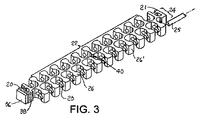
図3に示されるように、転向区間の内側半径に沿って走るベルトモジュール26の側縁部20は、電気伝導性要素を含む。電気伝導性要素は、銅またはアルミニウムなどの電気伝導性材料から作製されかつ側縁部20に取り付けられるかそれに埋設されるサイドプレート36であり得、または、それは、プラスチック用樹脂と混合されかつモジュールの縁部20を形成するように一緒に成型される電気伝導性繊維または粒子38であり得る。一方向のみに転向部分を切り抜ける必要のあるベルトに関して、電気伝導性材料は、一方の側縁部のみに存在すればよい。ラジアスベルトが左右両方の転向区間を切り抜ける場合、両方の側縁部が電気伝導性材料を有する。図3において、ベルトモジュール26は、隣接モジュール26’とベルト列24を形成する。2つのモジュールは継ぎ目40で互いに分離される。隣接する縁部モジュール26’は、電気伝導性要素のない側縁部21を有する。電気伝導性要素のない、ベルト列24の中間部分22が示されている。
As shown in FIG. 3, the
運搬経路の転向区間16に進入する側部柔軟性コンベヤベルト12が、図4に示されている。ベルトは、駆動スプロケットまたはドラムによってベルト移動方向42にモータ駆動される。直線セグメント18において、各ベルト列24に電気伝導性プレート36を備えたベルトの側縁部20は、サイドレール摩耗ストリップ32に沿って摺動可能である。ベルトが転向区間16に進入するとき、ベルトの内側縁部20は潰れる。アレイを形成する永久磁石34は永久磁界を生成し、永久磁界は、ベルトが転向部分を前進するとき、ベルト縁部20のプレート36などの電気伝導性材料中に電流を誘起する。誘起された電流は、レンツの法則によってアレイの永久磁界に対抗する反応性磁界を生成する。対抗磁界は、内側レールおよび磁石34のアレイからベルト12をはじく半径方向外向き力Fを生成する。半径方向外向き力Fは、ベルト12の内側縁部20が、転向区間16上を摺動することを防止する。このようにして、磁石および電気伝導性要素は、非接触式磁気ベアリングを形成する。摩擦接触は回避され、それによりベルト張力およびベルト摩耗は低減される。また、ベルト12が速く駆動されるほど、反発力Fは強くなる。永久磁石をハルバッハ配列(Hallbach array)状に配列することにより、電気伝導性要素に結合される磁界の強度は増大する。2つの磁界生成要素−永久磁石アレイおよび電気伝導性要素−は代替的に、永久磁石がコンベヤベルトの縁部に存在し電気伝導性要素が転向区間の内側半径においてコンベヤフレームに存在するように、位置を交換可能である。そのような配置は、半径方向外向き力が転向部分の内側半径からベルトを遠ざける磁気ベアリングを、同じように生成し得る。
A side
Claims (16)
転向区間を備えた運搬経路を含むコンベヤフレームと、
前記コンベヤフレームに支持されかつ第1磁界生成要素を備えた側縁部を有する側部柔軟性コンベヤベルトであって、
前記運搬経路に沿っておよび前記転向区間を通して駆動され、前記第1磁界生成要素を備えた前記側縁部が前記転向区間の内側半径に沿って前進する側部柔軟性コンベヤベルトと、
前記転向区間の前記内側半径に沿って前記運搬経路に沿って配置された第2磁界生成要素とを含み、
前記第1磁界生成要素が電気伝導性要素であり、前記第2磁界生成要素が永久磁石のアレイを形成し、またはその逆であり、
前記永久磁石のアレイが、前記電気伝導性要素中に電流を誘起する磁界を生成し、前記電流が、前記アレイの前記磁界によって対抗される誘起磁界を生成し、その結果、前記転向区間を前進する前記側部柔軟性コンベヤベルトに対抗する半径方向外向き力が生成される
ことを特徴とするコンベヤ。 A conveyor,
A conveyor frame including a transport path with a turning section;
A side flexible conveyor belt supported on the conveyor frame and having a side edge with a first magnetic field generating element;
A side flexible conveyor belt driven along the conveying path and through the turning section, the side edge with the first magnetic field generating element being advanced along the inner radius of the turning section;
A second magnetic field generating element disposed along the transport path along the inner radius of the turning section;
The first magnetic field generating element is an electrically conductive element and the second magnetic field generating element forms an array of permanent magnets, or vice versa,
The array of permanent magnets generates a magnetic field that induces a current in the electrically conductive element, and the current generates an induced magnetic field that is opposed by the magnetic field of the array, thereby advancing the turning section. A conveyor, characterized in that a radially outward force is generated against the side flexible conveyor belt.
前記ベルトモジュールの列の前記第1側縁部に沿って配置された電気伝導性プレートと
を含むことを特徴とするコンベヤベルト。 A series of rows of belt modules hinged to each other and extending across the width from the first side edge to the second side edge;
An electrically conductive plate disposed along the first side edge of the row of belt modules.
前記ベルトモジュールの列の前記第1側縁部に沿って配置された電気伝導性要素とを含み、
前記中間部分には電気伝導性要素がないことを特徴とするコンベヤベルト。 A series of rows of belt modules hingedly interconnected and extending across the width from the first side edge to the second side edge across the middle portion;
An electrically conductive element disposed along the first side edge of the row of belt modules;
Conveyor belt, characterized in that the intermediate part is free of electrically conductive elements.
Applications Claiming Priority (3)
| Application Number | Priority Date | Filing Date | Title |
|---|---|---|---|
| US201462063734P | 2014-10-14 | 2014-10-14 | |
| US62/063,734 | 2014-10-14 | ||
| PCT/US2015/051974 WO2016060818A2 (en) | 2014-10-14 | 2015-09-24 | Radius conveyor with magnetic bearing |
Publications (2)
| Publication Number | Publication Date |
|---|---|
| JP2017535495A true JP2017535495A (en) | 2017-11-30 |
| JP2017535495A5 JP2017535495A5 (en) | 2018-09-06 |
Family
ID=55747534
Family Applications (1)
| Application Number | Title | Priority Date | Filing Date |
|---|---|---|---|
| JP2017519543A Pending JP2017535495A (en) | 2014-10-14 | 2015-09-24 | Radius conveyor with magnetic bearings |
Country Status (8)
| Country | Link |
|---|---|
| US (1) | US9988214B2 (en) |
| EP (1) | EP3206971B1 (en) |
| JP (1) | JP2017535495A (en) |
| CN (1) | CN107074446B (en) |
| BR (1) | BR112017007557A2 (en) |
| DK (1) | DK3206971T3 (en) |
| MX (1) | MX2017004933A (en) |
| WO (1) | WO2016060818A2 (en) |
Families Citing this family (3)
| Publication number | Priority date | Publication date | Assignee | Title |
|---|---|---|---|---|
| EP3617104A1 (en) | 2018-08-31 | 2020-03-04 | Afher Eurobelt, S.A. | Tensioning system for a conveyor belt |
| CN109516085B (en) * | 2018-12-12 | 2020-06-30 | 福建龙净环保股份有限公司 | Electromagnetic drive type belt conveyor |
| EP3670392A1 (en) | 2018-12-21 | 2020-06-24 | Afher Eurobelt, S.A. | System for elongation control in conveyor belts |
Family Cites Families (17)
| Publication number | Priority date | Publication date | Assignee | Title |
|---|---|---|---|---|
| US3589300A (en) * | 1968-10-25 | 1971-06-29 | North American Rockwell | Magnetic suspension system |
| JPS60112512A (en) | 1983-11-18 | 1985-06-19 | Imamura Seisakusho:Kk | Deflection preventing apparatus for cylindrical or u-shaped conveyor |
| DE8530825U1 (en) * | 1985-10-31 | 1986-01-16 | Rexnord Kette GmbH & Co KG, 5240 Betzdorf | Curved chain conveyor |
| US4805761A (en) * | 1987-07-14 | 1989-02-21 | Totsch John W | Magnetic conveyor system for transporting wafers |
| IT1215730B (en) * | 1988-01-19 | 1990-02-22 | Regina Sud Spa | PERFECTED CHAIN CONVEYOR. |
| US4981208A (en) * | 1990-02-16 | 1991-01-01 | The Cambridge Wire Cloth Company | Magnetic drive spiral conveyor system |
| IT219317Z2 (en) * | 1990-03-20 | 1993-02-18 | Regina Sud Spa | PERFECTED CHAIN CONVEYOR |
| WO1994001354A1 (en) | 1992-07-07 | 1994-01-20 | Ebara Corporation | Magnetically levitated carrying apparatus |
| IT237914Y1 (en) * | 1997-09-18 | 2000-09-29 | Regina Sud Spa | IMPROVED MAGNETIC GUIDE |
| ITTV20040115A1 (en) | 2004-10-18 | 2005-01-18 | Plastomeccanica Spa | GUIDE, PARTICULARLY FOR CONVEYOR BELTS. |
| US7597188B2 (en) * | 2006-06-12 | 2009-10-06 | Habasit Ag | Belt module with magnetic properties |
| DE102007047000A1 (en) | 2007-10-01 | 2009-04-02 | Siemens Ag | Sorting system for piece goods sorting |
| ITMI20080345A1 (en) | 2008-02-29 | 2009-09-01 | Regina Catene Calibrate Spa | "CARRYING CARPET WITH GUIDELINES FOR CURVILINE PATHS AND FORMS FOR IT" |
| NL2001774C2 (en) * | 2008-07-07 | 2010-01-11 | Kaak Johan H B | Belt conveyor. |
| WO2012087577A2 (en) * | 2010-12-21 | 2012-06-28 | Laitram, L.L.C. | Closed-loop magnetic positioning of conveyor belts |
| EP2847111B1 (en) * | 2012-05-07 | 2019-08-14 | Laitram, L.L.C. | Conveyor having rollers actuated by electromagnetic induction |
| US8899409B2 (en) * | 2012-06-13 | 2014-12-02 | Ashworth Bros., Inc. | Conveyor belt link having wear resistant portion |
-
2015
- 2015-09-24 DK DK15850499.3T patent/DK3206971T3/en active
- 2015-09-24 US US15/512,730 patent/US9988214B2/en active Active
- 2015-09-24 MX MX2017004933A patent/MX2017004933A/en unknown
- 2015-09-24 JP JP2017519543A patent/JP2017535495A/en active Pending
- 2015-09-24 BR BR112017007557A patent/BR112017007557A2/en not_active Application Discontinuation
- 2015-09-24 WO PCT/US2015/051974 patent/WO2016060818A2/en active Application Filing
- 2015-09-24 CN CN201580056143.7A patent/CN107074446B/en active Active
- 2015-09-24 EP EP15850499.3A patent/EP3206971B1/en active Active
Also Published As
| Publication number | Publication date |
|---|---|
| CN107074446A (en) | 2017-08-18 |
| US9988214B2 (en) | 2018-06-05 |
| BR112017007557A2 (en) | 2018-02-06 |
| MX2017004933A (en) | 2017-12-04 |
| WO2016060818A3 (en) | 2017-05-04 |
| CN107074446B (en) | 2022-04-15 |
| US20170247192A1 (en) | 2017-08-31 |
| DK3206971T3 (en) | 2021-04-12 |
| WO2016060818A2 (en) | 2016-04-21 |
| EP3206971A2 (en) | 2017-08-23 |
| EP3206971B1 (en) | 2021-01-20 |
| EP3206971A4 (en) | 2018-05-23 |
Similar Documents
| Publication | Publication Date | Title |
|---|---|---|
| CN104271476B (en) | Conveyer with the roller activated by electromagnetic induction | |
| US9371194B2 (en) | Diverting conveyor with magnetically driven movers | |
| US9056720B2 (en) | Conveying device with articulated conveying element | |
| US9758317B2 (en) | Low profile transfer conveyor for use with conveyor systems | |
| AU2010298016B2 (en) | Belt drive conveyor with power tap off | |
| JP2017535495A (en) | Radius conveyor with magnetic bearings | |
| US8646596B2 (en) | Transverse belt | |
| JP6037456B2 (en) | Cross feed driven roller belt and conveyor | |
| US1422398A (en) | Conveying belt | |
| CA2614040A1 (en) | Conveying device | |
| US10273088B2 (en) | Conveyor belt with longitudinal rails | |
| CN103496545A (en) | Length-adjustable conveying flow channel | |
| ATE468287T1 (en) | SEPARATOR AND HANGING CONVEYOR EQUIPPED WITH IT | |
| JP2013107720A (en) | Apron feeder | |
| KR20090010132U (en) | Conveyer | |
| US10538392B2 (en) | Magnetic transmission for conveyor | |
| CN116750472A (en) | Three-in-three high-speed lane-dividing conveyor | |
| TH168921A (en) | Conveying device | |
| JP2018002334A (en) | Container alignment conveying device | |
| DE602007007502D1 (en) | Reciprocating floor conveyor for carrying and conveying loads |
Legal Events
| Date | Code | Title | Description |
|---|---|---|---|
| A521 | Request for written amendment filed |
Free format text: JAPANESE INTERMEDIATE CODE: A523 Effective date: 20180727 |
|
| A621 | Written request for application examination |
Free format text: JAPANESE INTERMEDIATE CODE: A621 Effective date: 20180727 |
|
| A977 | Report on retrieval |
Free format text: JAPANESE INTERMEDIATE CODE: A971007 Effective date: 20190409 |
|
| A131 | Notification of reasons for refusal |
Free format text: JAPANESE INTERMEDIATE CODE: A131 Effective date: 20190507 |
|
| A02 | Decision of refusal |
Free format text: JAPANESE INTERMEDIATE CODE: A02 Effective date: 20200204 |