JP2017534603A - Distillation equipment - Google Patents
Distillation equipment Download PDFInfo
- Publication number
- JP2017534603A JP2017534603A JP2017518463A JP2017518463A JP2017534603A JP 2017534603 A JP2017534603 A JP 2017534603A JP 2017518463 A JP2017518463 A JP 2017518463A JP 2017518463 A JP2017518463 A JP 2017518463A JP 2017534603 A JP2017534603 A JP 2017534603A
- Authority
- JP
- Japan
- Prior art keywords
- column
- distillation
- distillation column
- stream
- region
- Prior art date
- Legal status (The legal status is an assumption and is not a legal conclusion. Google has not performed a legal analysis and makes no representation as to the accuracy of the status listed.)
- Granted
Links
Images
Classifications
-
- B—PERFORMING OPERATIONS; TRANSPORTING
- B01—PHYSICAL OR CHEMICAL PROCESSES OR APPARATUS IN GENERAL
- B01D—SEPARATION
- B01D3/00—Distillation or related exchange processes in which liquids are contacted with gaseous media, e.g. stripping
-
- B—PERFORMING OPERATIONS; TRANSPORTING
- B01—PHYSICAL OR CHEMICAL PROCESSES OR APPARATUS IN GENERAL
- B01D—SEPARATION
- B01D3/00—Distillation or related exchange processes in which liquids are contacted with gaseous media, e.g. stripping
- B01D3/14—Fractional distillation or use of a fractionation or rectification column
-
- C—CHEMISTRY; METALLURGY
- C07—ORGANIC CHEMISTRY
- C07B—GENERAL METHODS OF ORGANIC CHEMISTRY; APPARATUS THEREFOR
- C07B63/00—Purification; Separation; Stabilisation; Use of additives
-
- C—CHEMISTRY; METALLURGY
- C07—ORGANIC CHEMISTRY
- C07C—ACYCLIC OR CARBOCYCLIC COMPOUNDS
- C07C45/00—Preparation of compounds having >C = O groups bound only to carbon or hydrogen atoms; Preparation of chelates of such compounds
- C07C45/78—Separation; Purification; Stabilisation; Use of additives
- C07C45/81—Separation; Purification; Stabilisation; Use of additives by change in the physical state, e.g. crystallisation
- C07C45/82—Separation; Purification; Stabilisation; Use of additives by change in the physical state, e.g. crystallisation by distillation
-
- C—CHEMISTRY; METALLURGY
- C07—ORGANIC CHEMISTRY
- C07C—ACYCLIC OR CARBOCYCLIC COMPOUNDS
- C07C47/00—Compounds having —CHO groups
- C07C47/02—Saturated compounds having —CHO groups bound to acyclic carbon atoms or to hydrogen
-
- B—PERFORMING OPERATIONS; TRANSPORTING
- B01—PHYSICAL OR CHEMICAL PROCESSES OR APPARATUS IN GENERAL
- B01D—SEPARATION
- B01D5/00—Condensation of vapours; Recovering volatile solvents by condensation
- B01D5/0057—Condensation of vapours; Recovering volatile solvents by condensation in combination with other processes
- B01D5/006—Condensation of vapours; Recovering volatile solvents by condensation in combination with other processes with evaporation or distillation
-
- F—MECHANICAL ENGINEERING; LIGHTING; HEATING; WEAPONS; BLASTING
- F25—REFRIGERATION OR COOLING; COMBINED HEATING AND REFRIGERATION SYSTEMS; HEAT PUMP SYSTEMS; MANUFACTURE OR STORAGE OF ICE; LIQUEFACTION SOLIDIFICATION OF GASES
- F25J—LIQUEFACTION, SOLIDIFICATION OR SEPARATION OF GASES OR GASEOUS OR LIQUEFIED GASEOUS MIXTURES BY PRESSURE AND COLD TREATMENT OR BY BRINGING THEM INTO THE SUPERCRITICAL STATE
- F25J2200/00—Processes or apparatus using separation by rectification
- F25J2200/80—Processes or apparatus using separation by rectification using integrated mass and heat exchange, i.e. non-adiabatic rectification in a reflux exchanger or dephlegmator
Landscapes
- Chemical & Material Sciences (AREA)
- Organic Chemistry (AREA)
- Crystallography & Structural Chemistry (AREA)
- Chemical Kinetics & Catalysis (AREA)
- Organic Low-Molecular-Weight Compounds And Preparation Thereof (AREA)
- Vaporization, Distillation, Condensation, Sublimation, And Cold Traps (AREA)
Abstract
本出願は、蒸留装置に関し、本出願の蒸留装置によれば、異性体の混合物、例えばn−ブチルアルデヒド及びiso−ブチルアルデヒドを含む原料の精製過程で発生するエネルギー損失を最小化し、製品を高純度で分離することによって、工程の経済性を向上させることができる。The present application relates to a distillation apparatus which, according to the distillation apparatus of the present application, minimizes energy loss generated during the purification process of raw materials containing a mixture of isomers, for example n-butyraldehyde and iso-butyraldehyde, and increases the product. By separating by purity, the economics of the process can be improved.
Description
本出願は、異性体(isomer)を分離する蒸留装置に関する。 The present application relates to a distillation apparatus for separating isomers.
n−ブタノール(n−butanol)のようなアルカノールは、例えば、コーティング液の製造時の溶媒などのような化学産業の多様な用途に用いられている。 Alkanols such as n-butanol are used in various applications in the chemical industry, for example, as solvents in the production of coating solutions.
例えば、n−ブタノールは、n−ブチルアルデヒド(n−butylaldehyde)の水素添加反応(hydrogenation)を通じて製造することができる。例えば、プロピレン(propylene)、一酸化炭素(CO)及び水素(H2)の混合ガスをオキソ反応(oxo reaction)に取り入れれば、ブチルアルデヒドを製造することができる。製造されたブチルアルデヒドは、通常、n−ブチルアルデヒドとiso−ブチルアルデヒドの混合物であり、前記混合物からn−ブチルアルデヒドを分離して水素添加反応を進行すれば、n−ブタノールを製造することができる。 For example, n-butanol can be produced through a hydrogenation reaction of n-butyraldehyde. For example, if a mixed gas of propylene, carbon monoxide (CO), and hydrogen (H 2 ) is introduced into an oxo reaction, butyraldehyde can be produced. The produced butyraldehyde is usually a mixture of n-butyraldehyde and iso-butyraldehyde. If n-butyraldehyde is separated from the mixture and a hydrogenation reaction proceeds, n-butanol can be produced. it can.
一般的な場合、化合物とその異性体は、沸点の差がその他の化合物に比べて相対的に小さいため、分離しにくく、例えば、前記n−ブチルアルデヒド及びその異性体であるiso−ブチルアルデヒドは、沸点の差が非常に小さいため、これを分離するのに多くのエネルギーを必要とする。したがって、高純度のn−ブチルアルデヒドを得るためには、相当なエネルギーが消耗し、前記異性体の分離工程でエネルギー消費量を一部節減するために、製品の純度をあきらめなければならない問題がある。 In general, the difference between the boiling point of the compound and its isomer is relatively small compared to other compounds, so that it is difficult to separate, for example, the n-butyraldehyde and its isomeric iso-butyraldehyde are The difference in boiling point is so small that a lot of energy is required to separate it. Therefore, in order to obtain high-purity n-butyraldehyde, considerable energy is consumed, and in order to save part of the energy consumption in the separation process of the isomer, there is a problem that the purity of the product must be given up. is there.
本出願は、異性質体を高純度及び高効率で分離する蒸留装置を提供することを目的にする。 This application aims at providing the distillation apparatus which isolate | separates an isomer with high purity and high efficiency.
本出願は、蒸留装置に関する。例示的な本出願の具現例による蒸留装置によれば、異性体の混合物、例えば下記化学式1の化合物と該化合物の異性体を含む原料の精製過程で発生するエネルギー損失を最小化し、製品を高純度で分離することによって、工程の経済性を向上させることができる。特に、本出願の蒸留装置では、2機の蒸留ユニットを利用したn−ブチルアルデヒド及びiso−ブチルアルデヒドの分離に最適化された温度及び圧力条件を提供し、これによって、本出願の蒸留装置を利用して高純度のn−ブチルアルデヒドを経済的に製造することができる。
The present application relates to a distillation apparatus. The distillation apparatus according to an exemplary embodiment of the present application minimizes energy loss generated in the purification process of a mixture of isomers, for example, a compound of
以下、図面を参照して本出願の蒸留装置を説明するが、前記図面は、例示的なものであって、前記蒸留装置の範囲が添付の図面に制限されるものではない。 Hereinafter, although the distillation apparatus of this application is demonstrated with reference to drawings, the said drawing is an illustration and the range of the said distillation apparatus is not restrict | limited to an accompanying drawing.
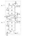
図1は、本出願の一具現例による蒸留装置を例示的に示す図である。図1に示されたように、例示的な前記蒸留装置は、2機の蒸留ユニット10、20及び熱交換器30を含み、例えば、前記蒸留装置は、第1蒸留ユニット10、第2蒸留ユニット20及び熱交換器30を含む。前記第1蒸留ユニット10は、第1蒸留塔100、第1凝縮器101、貯蔵槽102、及び第1再沸器103を含み、前記第2蒸留ユニット20は、第2蒸留塔200、第2凝縮器201、貯蔵槽202及び第2再沸器203を含む。
FIG. 1 is a diagram illustrating a distillation apparatus according to an embodiment of the present application. As shown in FIG. 1, the exemplary distillation apparatus includes two
前記第1蒸留塔100及び第2蒸留塔200は、原料に含まれた多成分物質をそれぞれの沸点の差によって分離し得る装置である。流入される原料の成分または分離しようとする成分などの沸点を考慮して、多様な形態を有する蒸留塔が本出願の蒸留装置において用いられることができる。本出願の蒸留装置において使用できる蒸留塔の具体的な種類は、特に制限されず、例えば、図1に示されたような一般的な構造の蒸留塔または内部に分離壁が設けられた分離壁型蒸留塔を使用することもできる。1つの例示で、前記第1蒸留塔100及び第2蒸留塔200の内部は、図1に示されたように、上部領域110、210、下部領域130、230及び中間領域120、220に区分され得る。本明細書で用語「上部領域」は、第1蒸留塔100及び第2蒸留塔200の構造において相対的に上側部分を意味し、例えば、前記第1蒸留塔100及び第2蒸留塔200において各蒸留塔の高さまたは長さ方向に3等分したときに分けられた3個の領域のうち最も上側部分を意味する。また、前記で「下部領域」は、それぞれ、第1蒸留塔100及び第2蒸留塔200の構造で相対的に下側部分を意味し、例えば、前記第1蒸留塔100及び第2蒸留塔200において各蒸留塔の高さまたは長さ方向に3等分したときに分けられた3個の領域のうち最も下側部分を意味する。また、本明細書で「中間領域」は、第1蒸留塔100及び第2蒸留塔200の構造において各蒸留塔の高さまたは長さ方向に3等分したときに分けられた3個の領域のうち中間領域を意味することができ、前記第1蒸留塔100及び第2蒸留塔200の上部領域110、210と下部領域130、230の間の領域を意味することができる。本明細書で蒸留塔の上部領域、下部領域及び中間領域は、互いに相対的な概念として使用され得る。前記第1蒸留塔100及び第2蒸留塔200の塔頂は、上部領域に含まれ、前記第1蒸留塔100及び第2蒸留塔200の塔底は、下部領域に含まれ、本明細書で特に別途定義しない限り、上部領域は、塔頂領域と同一の意味として使用され、下部領域は、塔底領域と同一の意味として使用される。前記第1蒸留塔100及び第2蒸留塔200としては、理論段数が50〜150段、70〜140段または90〜130段である蒸留塔を使用することができる。前記で、「理論段数」は、前記第1蒸留塔100及び第2蒸留塔200において気相及び液相のような2個の相が互いに平衡を成す仮想的な領域または段の数を意味する。
The
1つの具現例において、前記第1蒸留ユニット10は、図1のように、第1蒸留塔100、前記第1蒸留塔100にそれぞれ連結されている第1凝縮器101、貯蔵槽102及び第1再沸器103を含み、前記第2蒸留ユニット20は、図1に示されたように、第2蒸留塔200、前記第2蒸留塔200にそれぞれ連結されている第2凝縮器201、貯蔵槽202及び第2再沸器203を含む。例えば、前記第1蒸留塔100、第1凝縮器101、貯蔵槽102及び第1再沸器103は、前記第1蒸留塔100に流入された流体が流れることができるように、互いに流体連結(fluidically connected)されていてもよく、前記第2蒸留塔200、第2凝縮器201、貯蔵槽202及び第2再沸器203は、前記第2蒸留塔200に流入された流体が流れることができるように、互いに流体連結(fluidically connected)されていてもよい。前記「凝縮器」は、蒸留塔の外部に別途設置された装置であって、前記蒸留塔の塔頂から流出された流れを外部から流入された冷却水と接触させるなどの方式で冷却させるための装置を意味する。例えば、前記第1蒸留塔100の第1凝縮器101は、前記第1蒸留塔100の塔頂領域110から流出される第1塔頂流れF1-2を凝縮させる装置であり、前記第2蒸留塔200の第2凝縮器201は、前記第2蒸留塔200の塔頂領域210から流出される第2塔頂流れF2-2を凝縮させる装置であることができる。また、前記「再沸器」は、蒸留塔の外部に別途設置された加熱装置であり、前記蒸留塔の塔底から流出された高沸点成分の流れをさらに加熱及び蒸発させるための装置を意味することができる。例えば、前記第1蒸留塔100の第1再沸器103は、前記第1蒸留塔100の塔底領域130から流出される塔底流れF1-3を加熱する装置であり、後述する前記第2蒸留塔200の第2再沸器203は、前記第2蒸留塔200の塔底領域230から流出される塔底流れF2-3を加熱する装置であることができる。前記「貯蔵槽」は、前記蒸留塔から流出された流れを臨時的に貯蔵する槽または水槽を意味し、技術分野で知られた多様な槽や水槽を制限なく使用することができる。例えば、前記第1蒸留塔100の塔頂領域110から流出された第1塔頂流れF1-2は、第1凝縮器101で凝縮された後に貯蔵槽102に流入されて貯蔵され得、前記第2蒸留塔200の塔頂領域210から流出された第2塔頂流れF2-2は、第2凝縮器201で凝縮された後に貯蔵槽202に流入されて貯蔵され得る。
In one embodiment, the
前記第1蒸留塔100は、第1供給ポート121を含み、前記第2蒸留塔200は、第2供給ポート221を含む。一具現例において、前記第1供給ポート121は、前記第1蒸留塔100の中間領域120に位置し、前記第2供給ポート221は、前記第2蒸留塔200の中間領域220に位置する。
The
図1に示されたように、下記化学式1の化合物及び前記化合物の異性体を含む原料は、前記第1蒸留塔100の第1供給ポート121及び/または第2蒸留塔200の第2供給ポート221に流入される。
As shown in FIG. 1, the raw material containing the compound of the following
前記化学式1で、Rは、炭素数1〜12、例えば、炭素数1〜10、炭素数1〜8、炭素数1〜6または炭素数1〜4のアルキル基を示す。1つの例示で、前記化学式1の化合物は、例えば、n−ブチルアルデヒドであることができ、前記化合物の異性体は、iso−ブチルアルデヒドであることができる。
In the
例えば、図1のように、第1蒸留塔100と第2蒸留塔200が並列に連結された構造(以下、「並列構造」と称する)を有する蒸留装置の場合、前記化学式1の化合物及び前記化合物の異性体を含む原料は、前記第1蒸留塔100の第1供給ポート121及び第2蒸留塔200の第2供給ポート221にそれぞれ流入される。本出願の蒸留装置が、図1のように、前記第1蒸留塔100と第2蒸留塔200が並列に連結された構造を有する場合、エネルギー節減効果を極大化することができる。
For example, as shown in FIG. 1, in the case of a distillation apparatus having a structure in which the
1つの例示で、前記第1蒸留塔100の第1供給ポート121に流入された原料は、前記第1蒸留塔100の中間領域120に流入され、前記第1蒸留塔100の中間領域120に流入された原料F1-1は、前記第1蒸留塔100の塔頂領域110から流出される塔頂流れと前記第1蒸留塔100の塔底領域130から流出される塔底流れとにそれぞれ分離して流出される。この場合、前記第1蒸留塔100の塔底領域130から流出される塔底流れは、少なくとも1つ以上の流れに分離して流出され得る。例えば、前記第1蒸留塔100に流入された原料は、第1塔頂流れF1-2及び前記第1蒸留塔100の塔底領域130から流出される第1塔底流れF1-3、第2塔底流れF1-4及び第3塔底流れF1-5にそれぞれ分離して流出され得る。前記第1蒸留塔100の塔頂領域110から流出される第1塔頂流れF1-2は、前記第1凝縮器101に流入され、前記第1凝縮器101を通過した第1塔頂流れF1-2の一部または全部は、前記第1蒸留塔100の塔頂領域110に還流されるか、または製品に貯蔵され得る。1つの例示で、前記第1凝縮器101から流出された流れは、貯蔵槽102に流入されて貯蔵された後に、前記第1蒸留塔100に還流されるか、または製品に貯蔵され得る。また、前記第1蒸留塔100の塔底領域130から流出される第1塔底流れF1-3は、前記第1再沸器103に流入され、前記第1再沸器103を通過した第1塔底流れF1-3は、前記第1蒸留塔100の塔底領域130に流入され、前記第1蒸留塔100の塔底領域130から流出される第2塔底流れF1-4は、製品に貯蔵され得る。前記第1再沸器103に流入された第1塔底流れF1-3は、前記第1再沸器103内を通過する高圧スチームによって加熱され得、後述する熱交換器30によって前記高圧スチームの量は、適切に調節され得る。例えば、熱交換器30で熱交換が充分に起きる場合、前記高圧スチームは、全然使用しなくてもよいが、原料の流量または工程上の外乱が存在し、熱交換が円滑に起きない場合、分離効率が急激に劣化することがある。これによって、外乱(disturbance)に対しても壮健な(Robust)分離効率を維持し得るように、一時的に適切な量の高圧スチームが使用され得る。
In one example, the raw material that has flowed into the
前述したように、第1蒸留塔100と第2蒸留塔200が並列に連結された構造を有する蒸留装置の場合、前記第2蒸留塔200の第2供給ポート221に流入される流れは、前記化学式1の化合物及び前記化合物の異性体を含む原料の流れであることができる。前記第2蒸留塔200の第2供給ポート221に流入された原料は、前記第2蒸留塔200の中間領域220に流入され、前記第2蒸留塔200の中間領域220に流入された原料F2-1は、前記第2蒸留塔200の塔頂領域210から流出される塔頂流れと前記第2蒸留塔200の塔底領域230から流出される塔底流れとにそれぞれ分離して流出される。この場合、前記第2蒸留塔200の塔底領域230から流出される塔底流れは、少なくとも1つ以上の流れに分離して流出され得る。例えば、前記第2蒸留塔200に流入された原料は、第2塔頂流れF2-2及び前記第2蒸留塔200の塔底領域230から流出される第4塔底流れF2-3及び第5塔底流れF2-4にそれぞれ分離して流出され得る。前記第2蒸留塔200の塔底領域230から流出される第4塔底流れF2-3は、前記第2再沸器203に流入され、前記第2再沸器203を通過した第4塔底流れF2-3は、前記第2蒸留塔200の塔底領域230に流入され、前記第2蒸留塔200の塔底領域230から流出される第5塔底流れF2-4は、製品に貯蔵され得る。
As described above, in the case of a distillation apparatus having a structure in which the
前記第1蒸留塔100の塔底領域130から流出される第3塔底流れF1-5及び前記第2蒸留塔200の塔頂領域210から流出される第2塔頂流れF2-2は、前記熱交換器30に流入される。前記「熱交換器」は、蒸留塔の外部に別途設置され、互いに温度が異なる2つの流体流れの間に熱伝逹が円滑に起きるように熱交換を行う装置であり、例えば、前記熱交換器30は、前記第1蒸留塔100の塔底領域130から流出される第3塔底流れF1-5と前記第2蒸留塔200の塔頂領域210から流出される第2塔頂流れF2-2を熱交換させる装置であることができる。本出願の蒸留装置では、前記第1蒸留塔100の塔底領域130から流出される高沸点流れである第3塔底流れF1-5と前記第2蒸留塔200の塔頂領域210から流出される低沸点流れである第2塔頂流れF2-2を前記熱交換器30で互いに熱交換させることによって、前記凝縮器または再沸器を利用した凝縮及び加熱工程で必要なエネルギーを節減することができる。
The third column bottom stream F 1-5 flowing out from the
前記熱交換器30は、前記第1蒸留塔100の第3塔底流れF1-5及び前記第2蒸留塔200の第2塔頂流れF2-2が流れる配管に直接または間接的に連結されるように位置することができる。1つの例示で、前記熱交換器30は、第1蒸留塔100の第3塔底流れF1-5及び前記第2蒸留塔200の第2塔頂流れF2-2が流れる配管に直接連結されることによって、前記第3塔底流れF1-5及び第2塔頂流れF2-2を効率的に熱交換させることができる。
The
前記熱交換器30に流入された第3塔底流れF1-5及び第2塔頂流れF2-2は、熱交換され、前記熱交換器30を通過した第3塔底流れF1-5は、第1蒸留塔100の塔底領域130に還流され、前記熱交換器30を通過した第2塔頂流れF2-2は、第2凝縮器201に流入され、前記第2凝縮器201を通過した第2塔頂流れF2-2の一部または全部は、前記第2蒸留塔200の塔頂領域210に還流されるか、または製品に貯蔵され得る。1つの例示で、前記第2凝縮器201から流出された流れは、貯蔵槽202に流入されて貯蔵された後に、前記第2蒸留塔200に還流されるか、または製品に貯蔵され得る。
Third bottoms stream F 1-5 and the second overhead stream F 2-2 flowing into the
前記熱交換器30では、前記第3塔底流れF1-5が前記第1蒸留塔100に還流される前に、前記第2塔頂流れF2-2と熱交換され得、前記第2塔頂流れF2-2が第2凝縮器201に流入される前に、前記第3塔底流れF1-5と熱交換され得る。例えば、前記第2蒸留塔200の塔頂領域210から流出される低沸点成分の流れである第2塔頂流れF2-2は、第2蒸留塔200の塔頂領域210に還流される前に、熱交換器30を経由するようになり、この際、前記熱交換器30に熱を供給するようになる。これによって、前記第2蒸留塔200から流出される第2塔頂流れF2-2は、相対的に低い温度で前記第2蒸留塔200に還流され得る。これによって、前記第2蒸留塔200の塔頂領域210から流出される第2塔頂流れF2-2を凝縮させるのに必要な熱量を低減することができ、第2凝縮器201を利用した凝縮工程で使用される冷却水の量を減らすことによって、前記凝縮工程で所要されるコストを節減することができる。また、前記第1蒸留塔100の塔底領域130から流出される高沸点成分の流れである第3塔底流れF1-5は、第1蒸留塔100の塔底領域130に還流される前に、熱交換器30を経由するようになり、この際、前記第2塔頂流れF2-2から伝達された熱を供給され得る。これによって、前記第2塔頂流れF2-2は、前記第1蒸留塔100の塔底領域130に熱を供給するようになり、前記第1蒸留塔100の塔底領域130から流出される第1塔底流れF1-3を加熱するために、第1再沸器103で使用されるスチームの量を減らすことによって、コストを節減することができる。
In the
以下、本出願の一具現例による蒸留装置を利用してn−ブチルアルデヒド及びその異性体であるiso−ブチルアルデヒドを分離する過程を詳しく説明する。 Hereinafter, a process of separating n-butyraldehyde and its isomer iso-butyraldehyde using a distillation apparatus according to an embodiment of the present application will be described in detail.
1つの例示で、n−ブチルアルデヒドとその異性体であるiso−ブチルアルデヒドが含まれた原料F1-1が、前記第1蒸留塔100の第1供給ポート121及び第2蒸留塔200の第2供給ポート221にそれぞれ流入される。
In one example, a raw material F 1-1 containing n-butyraldehyde and iso-butyraldehyde, which is an isomer thereof, is supplied to the
この場合、前記第1供給ポート121に流入された前記原料F1-1に含まれる成分のうち相対的に低沸点成分である、iso−ブチルアルデヒドが濃厚な流れは、前記第1蒸留塔100の塔頂領域110から第1塔頂流れF1-2に流出され、相対的に高沸点成分である、n−ブチルアルデヒドが濃厚な流れは、前記第1蒸留塔100の塔底領域130から第1塔底流れF1-3、第2塔底流れF1-4及び第3塔底流れF1-5に流出され得る。前記第1蒸留塔100の塔頂領域110から流出された前記第1塔頂流れF1-2は、第1凝縮器101を通過して貯蔵槽102に流入され、前記貯蔵槽102から流出された流れの一部は、前記第1蒸留塔100の塔頂領域110に還流され、残りの一部は、製品に貯蔵され得る。前記製品は、高純度のiso−ブチルアルデヒドであることができる。一方、前記第1蒸留塔100の塔底領域130から流出された前記第1塔底流れF1-3は、第1再沸器103を経て第1蒸留塔100の塔底領域130に還流され、前記第2塔底流れF1-4は、製品に貯蔵され得る。前記製品は、高純度のn−ブチルアルデヒドであることができる。また、前記第3塔底流れF1-5は、熱交換器30で前記第2蒸留塔200の第2塔頂流れF2-2と熱交換された後、前記第1蒸留塔100の塔底領域130に還流され得る。
In this case, a flow having a high concentration of iso-butyraldehyde, which is a relatively low boiling point component among the components contained in the raw material F 1-1 flowing into the
また、前記第2供給ポート221に流入された前記原料F2-1流れに含まれる成分のうち相対的に低沸点成分である、iso−ブチルアルデヒドが濃厚な流れは、前記第2蒸留塔200の塔頂領域210から第2塔頂流れF2-2に流出され、相対的に高沸点である、n−ブチルアルデヒドが濃厚な流れは、前記第2蒸留塔200の塔底領域230から第4塔底流れF2-3及び第5塔底流れF2-4に流出され得る。流出された前記第2塔頂流れF2-2は、前記熱交換器30で前記第1蒸留塔100の第3塔底流れF1-5と熱交換された後、第2凝縮器201を通過して貯蔵槽202に流入され、前記貯蔵槽202から流出された流れの一部は、前記第2蒸留塔200の塔頂領域210に還流され、残りの一部は、製品に貯蔵され得る。前記製品は、高純度のiso−ブチルアルデヒドであることができる。また、前記原料F2-1に含まれる成分のうち相対的に高い沸点を有する高沸点流れは、前記第2蒸留塔200の塔底領域230から第4塔底流れF2-3及び第5塔底流れF2-4に流出され、前記第4塔底流れF2-3は、第2再沸器203を経て第2蒸留塔200の塔底領域230に還流され、前記第5塔底流れF2-4は、製品に貯蔵され得る。前記製品は、高純度のn−ブチルアルデヒドであることができる。
In addition, the iso-butyraldehyde-rich stream, which is a relatively low boiling point component among the components contained in the raw material F 2-1 stream flowing into the
本明細書で「低沸点流れ」は、低沸点及び高沸点成分を含む原料流れのうち相対的に沸点の低い成分が濃厚(rich)な流れを意味し、前記低沸点流れは、例えば、第1蒸留塔100及び第2蒸留塔200の塔頂領域210から流出される流れを意味する。また、「高沸点流れ」は、低沸点及び高沸点成分を含む原料流れのうち相対的に沸点の高い成分が濃厚(rich)な流れを意味し、前記高沸点流れは、例えば、第1蒸留塔100及び第2蒸留塔200の塔底領域230から流出される相対的に沸点の高い成分が濃厚な流れを意味する。前記で用語「濃厚な流れ」というのは、原料F1-1に含まれた低沸点成分及び高沸点成分それぞれの含量より前記第1蒸留塔100及び第2蒸留塔200の塔頂領域210から流出される流れに含まれた低沸点成分及び前記第1蒸留塔100及び第2蒸留塔200の塔底領域230から流出される流れに含まれた高沸点成分それぞれの含量がさらに高い流れを意味する。例えば、前記第1蒸留塔100の第1塔頂流れF1-2に含まれた低沸点成分と前記第2蒸留塔200の第2塔頂流れF2-2に含まれた低沸点成分が示すそれぞれの含量が50重量%以上、80重量%以上、90重量%以上、95重量%以上または99重量%以上の流れを意味するか、または前記第1蒸留塔100の第1塔底流れF1-3、第2塔底流れF1-4及び第3塔底流れF1-5に含まれた高沸点成分と第2蒸留塔200の第4塔底流れF2-3及び第5塔底流れF2-4に含まれた高沸点成分が示すそれぞれの含量が50重量%以上、80重量%以上、90重量%以上、95重量%以上または99重量%以上の流れを意味することができる。
As used herein, “low-boiling stream” means a stream in which a component having a relatively low boiling point out of a raw material stream containing low-boiling and high-boiling components is rich. This means a flow that flows out from the
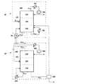
図2は、本出願の他の具現例による蒸留装置を例示的に示す図である。
図2のように、第1蒸留塔100と第2蒸留塔200が直列に連結された構造(以下、「直列構造」と称する)を有する蒸留装置の場合、前記化学式1の化合物及び前記化合物の異性体を含む原料は、前記第1蒸留塔100の第1供給ポート121に流入され、この場合、前記第1蒸留塔100の第2塔底流れF1-4は、前記第2蒸留塔200の第2供給ポート221に流入される流れである。本出願の蒸留装置が、図2のように、前記第1蒸留塔100と第2蒸留塔200が直列に連結された構造を有する場合、製造されるn−ブチルアルデヒドの純度を極大化することができる。
FIG. 2 is a diagram illustrating a distillation apparatus according to another embodiment of the present application.
As shown in FIG. 2, in the case of a distillation apparatus having a structure in which the
1つの例示で、図2のように、前記第1蒸留塔100の第1供給ポート121に流入された原料は、前記第1蒸留塔100の中間領域120に流入され、前記第1蒸留塔100の中間領域120に流入された原料F1-1は、前記第1蒸留塔100の塔頂領域110から流出される塔頂流れと前記第1蒸留塔100の塔底領域130から流出される塔底流れとにそれぞれ分離して流出される。この場合、前述した並列に連結された構造を有する蒸留装置と同様に、前記第1蒸留塔100の塔底領域130から流出される塔底流れは、少なくとも1つ以上の流れに分離して流出され得る。例えば、前記第1蒸留塔100に流入された原料は、第1塔頂流れF1-2及び前記第1蒸留塔100の塔底領域130から流出される第1塔底流れF1-3、第2塔底流れF1-4及び第3塔底流れF1-5にそれぞれ分離して流出され得る。前記第1蒸留塔100の塔頂領域110から流出される第1塔頂流れF1-2は、前記第1凝縮器101に流入され、前記第1凝縮器101を通過した第1塔頂流れF1-2の一部または全部は、前記第1蒸留塔100の塔頂領域110に還流されるか、または製品に貯蔵され得る。1つの例示で、前記第1凝縮器101から流出された流れは、貯蔵槽102に流入されて貯蔵された後に、前記第1蒸留塔100に還流されるか、または製品に貯蔵され得る。また、前記第1蒸留塔100の塔底領域130から流出される第1塔底流れF1-3は、前記第1再沸器103に流入され、前記第1再沸器103を通過した第1塔底流れF1-3は、前記第1蒸留塔100の塔底領域130に流入され得る。
For example, as shown in FIG. 2, the raw material that has flowed into the
前述したように、第1蒸留塔100と第2蒸留塔200が直列に連結された構造を有する蒸留装置の場合、前記第2蒸留塔200の第2供給ポート221に流入される流れは、前記第1蒸留塔100の第2塔底流れF1-4であることができる。前記第2蒸留塔200の第2供給ポート221に流入された第2塔底流れF1-4は、前記第2蒸留塔200の中間領域220に流入され、前記第2蒸留塔200の中間領域220に流入された第2塔底流れF1-4は、前記第2蒸留塔200の塔頂領域210から流出される塔頂流れと前記第2蒸留塔200の塔底領域230から流出される塔底流れとにそれぞれ分離して流出される。この場合、前述した並列に連結された構造を有する蒸留装置と同様に、前記第2蒸留塔200の塔底領域230から流出される塔底流れは、少なくとも1つ以上の流れに分離して流出され得る。例えば、前記第2蒸留塔200に流入された流れは、第2塔頂流れF2-2及び前記第2蒸留塔200の塔底領域230から流出される第4塔底流れF2-3及び第5塔底流れF2-4にそれぞれ分離して流出され得る。前記第2蒸留塔200の塔底領域230から流出される第4塔底流れF2-3は、前記第2再沸器203に流入され、前記第2再沸器203を通過した第4塔底流れF2-3は、前記第2蒸留塔200の塔底領域230に流入され、前記第2蒸留塔200の塔底領域230から流出される第5塔底流れF2-4は、製品に貯蔵され得る。
As described above, in the case of a distillation apparatus having a structure in which the
前記第1蒸留塔100の塔底領域130から流出される第3塔底流れF1-5及び前記第2蒸留塔200の塔頂領域210から流出される第2塔頂流れF2-2は、前記熱交換器30に流入される。前述したように、前記熱交換器30は、前記第1蒸留塔100の塔底領域130から流出される第3塔底流れF1-5と前記第2蒸留塔200の塔頂領域210から流出される第2塔頂流れF2-2を熱交換させる装置であることができる。本出願の蒸留装置では、前記第1蒸留塔100の塔底領域130から流出される高沸点流れである第3塔底流れF1-5と前記第2蒸留塔200の塔頂領域210から流出される低沸点流れである第2塔頂流れF2-2を前記熱交換器30で互いに熱交換させることによって、前記凝縮器または再沸器を利用した凝縮及び加熱工程で必要なエネルギーを節減することができ、高純度でn−ブチルアルデヒドを製造することができる。
The third column bottom stream F 1-5 flowing out from the
前記熱交換器30に関する説明は、前述した第1蒸留塔100と第2蒸留塔200が並列に連結された構造を有する蒸留装置で説明したものと同一なので、省略する。
Since the description regarding the
以下、本出願のさらに他の具現例による第1蒸留塔100と第2蒸留塔200が直列に連結された構造を有する蒸留装置を利用してn−ブチルアルデヒド及びその異性体であるiso−ブチルアルデヒドを分離する過程を詳しく説明する。
Hereinafter, n-butyraldehyde and iso-butyl, which is an isomer thereof, using a distillation apparatus having a structure in which a
1つの例示で、n−ブチルアルデヒドとその異性体であるiso−ブチルアルデヒドが含まれた原料F1-1が前記第1蒸留塔100の第1供給ポート121に流入される。
In one example, a raw material F 1-1 containing n-butyraldehyde and iso-butyraldehyde, which is an isomer thereof, flows into the
この場合、前記第1供給ポート121に流入された前記原料F1-1に含まれる成分のうち相対的に低沸点成分である、iso−ブチルアルデヒドが濃厚な流れは、前記第1蒸留塔100の塔頂領域110から第1塔頂流れF1-2に流出され、相対的に高沸点成分である、n−ブチルアルデヒドが濃厚な流れは、前記第1蒸留塔100の塔底領域130から第1塔底流れF1-3、第2塔底流れF1-4及び第3塔底流れF1-5に流出され得る。前記第1蒸留塔100の塔頂領域110から流出された前記第1塔頂流れF1-2は、第1凝縮器101を通過して貯蔵槽102に流入され、前記貯蔵槽102から流出された流れの一部は、前記第1蒸留塔100の塔頂領域110に還流され、残りの一部は、製品に貯蔵され得る。前記製品は、高純度のiso−ブチルアルデヒドであることができる。一方、前記第1蒸留塔100の塔底領域130から流出された前記第1塔底流れF1-3は、第1再沸器103を経て第1蒸留塔100の塔底領域130に還流され、前記第2塔底流れF1-4は、第2蒸留塔200の第2供給ポート221に流入され得る。また、前記第3塔底流れF1-5は、熱交換器30で前記第2蒸留塔200の第2塔頂流れF2-2と熱交換された後、前記第1蒸留塔100の塔底領域130に還流され得る。
In this case, a flow having a high concentration of iso-butyraldehyde, which is a relatively low boiling point component among the components contained in the raw material F 1-1 flowing into the
また、前記第2供給ポート221に流入された前記第2塔底流れF1-4は、n−ブチルアルデヒド及び高沸点成分を含む流れであり、したがって、前記第2塔底流れF1-4に含まれる成分のうち相対的に低沸点成分である、n−ブチルアルデヒドが濃厚な流れは、前記第2蒸留塔200の塔頂領域210から第2塔頂流れF2-2に流出され、相対的に高沸点成分(heavy components)が濃厚な流れは、前記第2蒸留塔200の塔底領域230から第4塔底流れF2-3及び第5塔底流れF2-4に流出され得る。流出された前記第2塔頂流れF2-2は、前記熱交換器30で前記第1蒸留塔100の第3塔底流れF1-5と熱交換された後、第2凝縮器201を通過して貯蔵槽202に流入され、前記貯蔵槽202から流出された流れの一部は、前記第2蒸留塔200の塔頂領域210に還流され、残りの一部は、製品に貯蔵され得る。前記製品は、超高純度のn−ブチルアルデヒドであることができる。また、前記第2塔頂流れF2-2に含まれる成分のうち相対的に高い沸点を有する高沸点成分の流れは、前記第2蒸留塔200の塔底領域230から第4塔底流れF2-3及び第5塔底流れF2-4に流出され、前記第4塔底流れF2-3は、第2再沸器203を経て第2蒸留塔200の塔底領域230に還流され、前記第5塔底流れF2-4は、製品に貯蔵され得る。前記製品は、例えば、n−ブチルアルデヒド、ブチルアルコール、またはこれらのダイマー及びトライマーを含むことができる。
In addition, the second column bottom flow F 1-4 flowing into the
1つの例示で、前記第2蒸留塔200の塔底領域230から流出される第5塔底流れF2-4の一部は、第1蒸留塔100の塔底領域130、例えば、理論段数が50〜150である第1蒸留塔100の45〜145段に流入され得る。これによって、前記第5塔底流れF2-4内に一部残っていることができるn−ブチルアルデヒドを第1蒸留塔100の塔底領域130に供給することができ、より高い純度でn−ブチルアルデヒドを製造することができる。この場合、前記第2蒸留塔200の塔底領域230から流出される第5塔底流れF2-4の流量(ton/hr)に対する前記第1蒸留塔100の塔底領域130に流入される流れの流量(ton/hr)の比率は、1:0.85〜1:0.95であることができ、前記第1蒸留塔100の塔底領域130に流入される流れの流量の比率を前記範囲に調節することによって、より高い純度のn−ブチルアルデヒドを製造することができる。
As an example, a part of the fifth bottom stream F 2-4 that flows out from the
一具現例で、本出願の蒸留装置は、下記一般式1を満足する。
In one embodiment, the distillation apparatus of the present application satisfies the following
[一般式1]
Tt-2−Tb-3≧8℃
[General Formula 1]
T t-2 -T b-3 ≧ 8 ℃
前記一般式1で、Tt-2は、第2塔頂流れF2-2の温度を示し、Tb-3は、第3塔底流れF1-5の温度を示す。
In the
本出願の蒸留装置が前記一般式1を満足することによって、前記のような並列構造を有する蒸留装置または直列構造を有する蒸留装置を利用して前記化学式1の化合物、特に、n−ブチルアルデヒドを優れた効率及び高純度で分離し得る。すなわち、前記蒸留装置で、前記第2塔頂流れF2-2の温度と第3塔底流れF1-5の温度の差が前記一般式1を満足するように調節することによって、前記第2塔頂流れF2-2の温度と第3塔底流れF1-5との間に熱交換効率を最大化することができ、これによって、前記化学式1の化合物、特に、n−ブチルアルデヒドを優れたな効率及び高純度で分離し得る。
When the distillation apparatus of the present application satisfies the
1つの例示で、前記第2蒸留塔200の塔頂領域210から流出される第2塔頂流れF2-2の温度と前記第1蒸留塔100の塔底領域130から流出される第3塔底流れF1-5の温度の差は、前記一般式1を満足すれば、特に制限されるものではなく、例えば、8℃以上、9℃以上、10℃以上または13℃以上であることができる。前記第2蒸留塔200の塔頂領域210から流出される第2塔頂流れF2-2の温度と前記第1蒸留塔100の塔底領域130から流出される第3塔底流れF1-5の温度の差が大きいほど熱交換効率に優れているので、前記差の上限値は、特に制限されるものではなく、例えば、前記第2蒸留塔200の塔頂領域210から流出される第2塔頂流れF2-2の温度と前記第1蒸留塔100の塔底領域130から流出される第3塔底流れF1-5の温度の差は、工程効率を考慮して、100℃以下であることができる。
In one example, the temperature of the second top stream F 2-2 flowing out from the
1つの例示で、本出願の蒸留装置は、下記一般式2を満足する。 In one example, the distillation apparatus of the present application satisfies the following general formula 2.
[一般式2]
P2/P1≧20
[General formula 2]
P 2 / P 1 ≧ 20
前記一般式2で、P1は、第1蒸留塔100の塔頂領域110の圧力(Kg/cm2g)を示し、P2は、第2蒸留塔200の塔頂領域210の圧力(Kg/cm2g)を示す。
In the general formula 2, P 1 represents the pressure (Kg / cm 2 g) of the
本出願の蒸留装置が前記一般式2を満足するによって、前記のような並列構造を有する蒸留装置または直列構造を有する蒸留装置を利用して前記化学式1の化合物、特に、n−ブチルアルデヒドを優れた効率及び高純度で分離し得る。すなわち、前記蒸留装置で、前記第1蒸留塔100の塔頂領域110の圧力と前記第2蒸留塔200の塔頂領域210の圧力の比が、前記一般式2を満足するように調節することによって、前記第2塔頂流れF2-2の温度と第3塔底流れF1-5との間に熱交換効率を最大化でき、これによって、前記化学式1の化合物、特に、n−ブチルアルデヒドを優れた効率及び高純度で分離し得る
When the distillation apparatus of the present application satisfies the general formula 2, the compound of the
例えば、前記熱交換器30で熱交換効率を高めるために前記第1蒸留塔100の内部の温度は、前記第2蒸留塔200の内部の温度より低く維持され得、これによって、前記第1蒸留塔100の塔頂領域110の圧力は、第2蒸留塔200塔頂領域の圧力より低く維持され得る。
For example, the temperature inside the
1つの例示で、前記第1蒸留塔100の塔頂領域110の圧力と前記第2蒸留塔200の塔頂領域210の圧力の比は、前記一般式2を満足すれば、特に制限されるものではなく、例えば20以上、25以上、35以上、50以上、80以上または120以上であることができる。前記第1蒸留塔100の塔頂領域110の圧力と前記第2蒸留塔200の塔頂領域210の圧力の比が大きいほど熱交換効率に優れているので、前記の比率の上限値は、特に制限されるものではなく、例えば、前記第1蒸留塔100の塔頂領域110の圧力と前記第2蒸留塔200の塔頂領域210の圧力の比は、工程効率を考慮して、300以下、または200以下であることができる。
For example, the ratio of the pressure in the
本出願の蒸留装置が前述したような並列構造を有する場合、前記第2蒸留塔200の塔頂領域210から流出される第2塔頂流れF2-2の温度は、前記一般式1を満足すれば、特に制限されるものではなく、100℃〜110℃、例えば、102℃〜108℃または104℃〜106℃であることができる。また、前記第1蒸留塔100の塔底領域130から排出される第3塔底流れF1-5の温度は、前記一般式1を満足すれば、特に制限されるものではなく、90℃〜100℃、例えば、92℃〜98℃または94℃〜96℃であることができる。また、この場合、前記第1蒸留塔100の塔頂領域110の圧力は、前記一般式2を満足すれば、特に制限されるものではなく、0.01〜0.1Kg/cm2g、0.01〜0.07Kg/cm2gまたは0.015〜0.03Kg/cm2gであることができる。また、前記第2蒸留塔200の塔頂領域210の圧力は、前記一般式2を満足すれば、特に制限されるものではなく、2.3〜2.7Kg/cm2g、2.35〜2.65Kg/cm2gまたは2.4〜2.6Kg/cm2gであることができる。
When the distillation apparatus of the present application has a parallel structure as described above, the temperature of the second overhead stream F 2-2 flowing out from the
1つの例示で、本出願の蒸留装置が前述したような並列構造を有する場合、前記第1蒸留塔100の塔頂領域110の温度は、60℃〜70℃、例えば、62℃〜68℃または64℃〜66℃であることができ、前記第1蒸留塔100の塔底領域130の温度は、90℃〜100℃、例えば、92℃〜98℃または94℃〜96℃であることができるが、これに制限されるものではない。また、この場合、前記第2蒸留塔200の塔頂領域210の温度は、100℃〜110℃、例えば、102℃〜108℃または104℃〜106℃であることができ、前記第2蒸留塔200の塔底領域230の温度は、120℃〜140℃、例えば、124℃〜138℃または126℃〜134℃であることができるが、これに制限されるものではない。
For example, when the distillation apparatus of the present application has a parallel structure as described above, the temperature of the
1つの例示で、本出願の蒸留装置が前述したような並列構造を有する場合には、下記一般式3を満足することができる。 For example, when the distillation apparatus of the present application has a parallel structure as described above, the following general formula 3 can be satisfied.
[一般式3]
0.3≦F1/F2≦3.0
[General formula 3]
0.3 ≦ F 1 / F 2 ≦ 3.0
前記一般式3で、F1は、第1蒸留塔100の第1供給ポート121に流入される原料の流量(ton/hr)であり、F2は、第2蒸留塔200の第2供給ポート221にそれぞれ流入される原料の流量(ton/hr)を示す。
In Formula 3, F 1 is a flow rate (ton / hr) of the raw material flowing into the
前記蒸留装置で、前記第1蒸留塔100の第1供給ポート121に流入される原料F1-1の流量と前記第2蒸留塔200の第2供給ポート221にそれぞれ流入される原料F2-1の流量の比を前記一般式3の範囲内に調節することによって、エネルギー節減効果を極大化することができる。
In the distillation apparatus, the flow rate of the raw material F 1-1 that flows into the
1つの例示で、前記第1蒸留塔100の第1供給ポート121に流入される原料F1−1の流量と前記第2蒸留塔200の第2供給ポート221にそれぞれ流入される原料F2-1の流量の比は、前述した範囲内であれば、特に制限されるものではなく、例えば、0.3〜3.0、0.6〜2.0、0.7〜1.7、0.8〜1.4または0.9〜1.2であることができる。
In one example, the flow rate of the raw material F1-1 that flows into the
また、前記第1蒸留塔100の第1供給ポート121に流入される原料F1-1の流量は、前記一般式3を満足すれば、特に制限されるものではないが、10〜30ton/hr、例えば、14〜26ton/hrまたは18〜22ton/hrであることができ、前記第2蒸留塔200の第2供給ポート221にそれぞれ流入される原料F2-1の流量は、前記一般式3を満足すれば、特に制限されるものではないが、10〜30ton/hr、例えば、14〜26ton/hrまたは18〜22ton/hrであることができる。
Further, the flow rate of the raw material F 1-1 flowing into the
本出願の蒸留装置が前述したような並列構造を有する場合、前記第1蒸留塔100の塔頂領域110から流出される第1塔頂流れF1-2及び前記第2蒸留塔200の塔頂領域210から流出される第2塔頂流れF2-2内のiso−ブチルアルデヒドの含量は、90%以上、好ましくは99%以上であることができ、前記第1蒸留塔100の塔底領域130から流出される第2塔底流れF1-4及び第2蒸留塔200の塔底領域230から流出される第5塔底流れF2-4内のn−ブチルアルデヒドの含量は、90%以上、好ましくは99%以上であることができる。
When the distillation apparatus of the present application has a parallel structure as described above, the first top stream F 1-2 flowing out from the
本出願の蒸留装置が前述したような直列構造を有する場合、前記第2蒸留塔200の塔頂領域210から流出される第2塔頂流れF2-2の温度は、前記一般式1を満足すれば、特に制限されるものではなく、100℃〜110℃、例えば、102℃〜108℃または104℃〜106℃であることができる。また、前記第1蒸留塔100の塔底領域130から排出される第3塔底流れF1-5の温度は、前記一般式1を満足すれば、特に制限されるものではなく、90℃〜100℃、例えば、92℃〜98℃または94℃〜96℃であることができる。また、この場合、前記第1蒸留塔100の塔頂領域110の圧力は、前記一般式2を満足すれば、特に制限されるものではなく、0.01〜0.1Kg/cm2g、0.012〜0.07Kg/cm2gまたは0.015〜0.03Kg/cm2gであることができる。また、前記第2蒸留塔200の塔頂領域210の圧力は、前記一般式2を満足すれば、特に制限されるものではなく、1.0〜2.0Kg/cm2g、1.2〜2.0Kg/cm2gまたは1.4〜1.6Kg/cm2gであることができる。
When the distillation apparatus of the present application has a series structure as described above, the temperature of the second overhead stream F 2-2 flowing out from the
1つの例示で、本出願の蒸留装置が前述したような直列構造を有する場合、前記第1蒸留塔100の塔頂領域110の温度は、60℃〜70℃、例えば、62℃〜68℃または64℃〜66℃であることができ、前記第1蒸留塔100の塔底領域130の温度は、90℃〜100℃、例えば、92℃〜98℃または94℃〜96℃であることができるが、これに制限されるものではない。また、この場合、前記第2蒸留塔200の塔頂領域210の温度は、100℃〜110℃、例えば、102℃〜108℃または104℃〜106℃であることができ、前記第2蒸留塔200の塔底領域230の温度は、120℃〜140℃、例えば、124℃〜138℃または126℃〜134℃であることができるが、これに制限されるものではない。
For example, when the distillation apparatus of the present application has a series structure as described above, the temperature of the
本出願の蒸留装置が前述したような直列構造を有する場合、前記第1蒸留塔100の塔頂領域110から流出される第1塔頂流れF1-2内のiso−ブチルアルデヒドの含量は、90%以上、好ましくは99%以上であることができ、前記第2蒸留塔200の塔頂領域210から流出される第2塔頂流れF2-2内のn−ブチルアルデヒドの含量は、90%以上、好ましくは99%以上であることができる。
When the distillation apparatus of the present application has a serial structure as described above, the content of iso-butyraldehyde in the first overhead stream F 1-2 discharged from the
本出願は、また、前記化学式1の化合物の製造方法に関する。
例示的な本出願の製造方法は、前述した蒸留装置を利用して行われることができ、これによって、前述した蒸留装置で記載された内容と重複される内容は省略する。
The present application also relates to a method for producing the compound of
The exemplary manufacturing method of the present application can be performed by using the above-described distillation apparatus, and thus, the contents overlapping with the contents described in the above-described distillation apparatus are omitted.
本出願の製造方法の一具現例は、i)第1蒸留塔100の第1供給ポート121及び第2蒸留塔200の第2供給ポート221に下記化学式1の化合物及び前記化合物の異性体を含む原料をそれぞれ流入する段階;ii)前記第1供給ポート121に流入された原料を前記第1蒸留塔100の塔頂領域110から流出される第1塔頂流れF1-2;及び前記第1蒸留塔100の塔底領域130から流出される第1塔底流れF1-3、第2塔底流れF1-4及び第3塔底流れF1-5にそれぞれ流出させる段階;iii)前記第2供給ポート221に流入された原料を、前記第2蒸留塔200の塔頂領域210から流出される第2塔頂流れF2-2;及び前記第2蒸留塔200の塔底領域230から流出される第4塔底流れF2-3及び第5塔底流れF2-4にそれぞれ流出させる段階;iv)前記第2塔頂流れF2-2と前記第3塔底流れF1-5を熱交換させる段階;及びv)前記第1蒸留塔100の塔底領域130で前記化学式1の化合物を分離し、前記第1蒸留塔100の塔頂領域110及び第2蒸留塔200の塔頂領域210で前記化学式1の化合物の異性体を分離する段階を含む。
In one embodiment of the production method of the present application, i) the
前記化学式1でRは炭素数1〜12のアルキル基である。前記化学式1の化合物は、例えば、n−ブチルアルデヒドまたはiso−ブチルアルデヒドであることができ、1つの例示で、n−ブチルアルデヒドであることができる。
In
前記製造方法は、前述した並列構造を有する蒸留装置を利用して行われることができ、前記並列構造を有する蒸留装置と関する説明は、前述したものと同様なので、省略する。 The manufacturing method can be performed using the distillation apparatus having the parallel structure described above, and the description of the distillation apparatus having the parallel structure is the same as that described above, and thus the description thereof is omitted.
前記i)〜v)の各段階は、それぞれ独立して、有機的に結合されているので、各境界が明確に時間の順序によって区分されるものではなく、これによって、前記i)〜v)の各段階は、順次に行われるか、またはそれぞれ独立して、同時に行われることができる。 Since each step of i) to v) is independently organically coupled, each boundary is not clearly separated by the order of time. These steps can be performed sequentially or independently and simultaneously.
前記製造方法は、下記一般式1及び2を満足し、これに関する説明は、前述したものと同様なので、省略する。
The manufacturing method satisfies the following
[一般式1]
Tt-2−Tb-3≧8℃
[General Formula 1]
T t-2 -T b-3 ≧ 8 ℃
[一般式2]
P2/P1≧20
[General formula 2]
P 2 / P 1 ≧ 20
前記一般式1で、Tt-2は、第2塔頂流れF2-2の温度を示し、Tb-3は、第3塔底流れF1-5の温度を示し、
前記一般式2で、P1は、第1蒸留塔100の塔頂領域110の圧力(Kg/cm2g)を示し、P2は、第2蒸留塔200の塔頂領域210の圧力(Kg/cm2g)を示す。
In the
In the general formula 2, P 1 represents the pressure (Kg / cm 2 g) of the
本出願の製造方法の他の具現例は、a)第1蒸留塔100の第1供給ポート121に下記化学式1の化合物及び前記化合物の異性体を含む原料を流入する段階;b)前記流入された原料を前記第1蒸留塔100の塔頂領域110から流出される第1塔頂流れF1-2;及び前記第1蒸留塔100の塔底領域130から流出される第1塔底流れF1-3、第2塔底流れF1-4及び第3塔底流れF1-5にそれぞれ流出させる段階;c)前記第1塔底流れF1-3を第2蒸留塔200の第2供給ポート221に流入させる段階;d)前記第2供給ポート221に流入された流れを、前記第2蒸留塔200の塔頂領域210から流出される第2塔頂流れF2-2;及び前記第2蒸留塔200の塔底領域230から流出される第4塔底流れF2-3及び第5塔底流れF2-4にそれぞれ流出させる段階;e)前記第2塔頂流れF2-2と前記第3塔底流れF1-5を熱交換させる段階;及びf)第2蒸留塔200の塔頂領域210で前記化学式1の化合物を分離し、前記第1蒸留塔100の塔頂領域110で化合物の異性体を分離する段階を含む。
In another embodiment of the manufacturing method of the present application, a) a step of feeding a raw material containing a compound of
前記化学式1で、Rは、炭素数1〜12のアルキル基である。
In
前記製造方法は、前述した直列構造を有する蒸留装置を利用して行われることができ、前記直列構造を有する蒸留装置に関する説明は、前述したものと同様なので、省略する。 The manufacturing method can be performed using the distillation apparatus having the above-described serial structure, and the description of the distillation apparatus having the serial structure is the same as that described above, and thus will be omitted.
前述したように、前記a)〜f)の各段階は、それぞれ独立して、有機的に結合されているので、各境界が明確に時間の順序によって区分されるものではなく、これによって、前記a)〜f)の各段階は、順次に行われるか、またはそれぞれ独立して、同時に行われることができる。 As described above, the steps a) to f) are organically coupled independently of each other, so that the boundaries are not clearly separated by the order of time. The steps a) to f) can be performed sequentially or independently and simultaneously.
前記製造方法は、下記一般式1及び2を満足し、これに関する説明は、前述したものと同様なので、省略する。
The manufacturing method satisfies the following
[一般式1]
Tt-2−Tb-3≧8℃
[General Formula 1]
T t-2 -T b-3 ≧ 8 ℃
[一般式2]
P2/P1≧20
[General formula 2]
P 2 / P 1 ≧ 20
前記一般式1で、Tt-2は、第2塔頂流れの温度を示し、Tb-3は、第3塔底流れF1-5の温度を示し、
前記一般式2で、P1は、第1蒸留塔100の塔頂領域110の圧力(Kg/cm2g)を示し、P2は、第2蒸留塔200の塔頂領域210の圧力(Kg/cm2g)を示す。
In the
In the general formula 2, P 1 represents the pressure (Kg / cm 2 g) of the
本出願の蒸留装置によれば、異性体の混合物、例えば下記n−ブチルアルデヒド及びiso−ブチルアルデヒドを含む原料の精製過程で発生するエネルギー損失を最小化し、製品を高純度で分離することによって、工程の経済性を向上させることができる。 According to the distillation apparatus of the present application, by minimizing the energy loss generated in the purification process of the raw material containing a mixture of isomers, for example, n-butyraldehyde and iso-butyraldehyde, and separating the product with high purity, The economics of the process can be improved.
以下、本発明による実施例及び本発明によらない比較例を通じて本発明を詳しく説明するが、本発明の範囲が提示された実施例によって制限されるものではない。 Hereinafter, the present invention will be described in detail through examples according to the present invention and comparative examples not according to the present invention, but the scope of the present invention is not limited by the presented examples.
実施例1
図1の蒸留装置を使用してn−ブチルアルデヒド及びiso−ブチルアルデヒドを分離した。具体的には、n−ブチルアルデヒド及びiso−ブチルアルデヒドを含む原料を理論段数が100段である第1蒸留塔及び理論段数が100段である第2蒸留塔にそれぞれ流入した。この場合、前記第1蒸留塔に流入される原料の流量と第2蒸留塔に流入される原料の流量の比率を2:3になるようにした。
Example 1
Using the distillation apparatus of FIG. 1, n-butyraldehyde and iso-butyraldehyde were separated. Specifically, the raw materials containing n-butyraldehyde and iso-butyraldehyde were respectively flowed into the first distillation column having 100 theoretical plates and the second distillation column having 100 theoretical plates. In this case, the ratio of the flow rate of the raw material flowing into the first distillation column and the flow rate of the raw material flowing into the second distillation column was set to 2: 3.
前記第1蒸留塔の塔頂領域から排出される第1塔頂流れの一部は、第1凝縮器を経て前記第1蒸留塔の塔頂領域に還流させた。前記第1塔頂流れの残りの一部は、iso−ブチルアルデヒドを含む製品に分離して貯蔵し、前記第1蒸留塔の塔底領域から排出される第1塔底流れは、第1再沸器を経て前記第1蒸留塔の塔底領域に還流させた。前記第1蒸留塔の塔底領域から流出される第2塔底流れは、n−ブチルアルデヒドを含む製品に分離して貯蔵した。前記第1蒸留塔の塔底領域から流出される第3塔底流れは、熱交換器に流入させ、前記熱交換器に流入された第2蒸留塔の第2塔頂流れと熱交換させた後、前記熱交換器を経て第1蒸留塔の塔底領域に還流させた。この場合、前記第1蒸留塔塔頂領域の運転圧力を0.02Kg/cm2gに調節し、運転温度は、65℃に調節し、前記第1蒸留塔塔底領域の運転温度は、95℃に調節した。 A part of the first top stream discharged from the top region of the first distillation column was refluxed to the top region of the first distillation column via the first condenser. The remaining part of the first top stream is separated and stored in a product containing iso-butyraldehyde, and the first bottom stream discharged from the bottom region of the first distillation tower is the first recycle. The solution was refluxed to the bottom area of the first distillation column through a boiling machine. The second bottom stream flowing out from the bottom region of the first distillation column was separated into a product containing n-butyraldehyde and stored. The third bottom stream flowing out from the bottom region of the first distillation column was introduced into a heat exchanger, and heat exchange was performed with the second top stream of the second distillation column that was introduced into the heat exchanger. Thereafter, the mixture was refluxed to the bottom area of the first distillation column through the heat exchanger. In this case, the operating pressure in the top region of the first distillation column is adjusted to 0.02 Kg / cm 2 g, the operating temperature is adjusted to 65 ° C., and the operating temperature in the bottom region of the first distillation column is 95 Adjusted to ° C.
一方、前記第2蒸留塔の塔頂領域から排出される第2塔頂流れは、熱交換器に流入させ、前記第3塔底流れと熱交換させた後、前記熱交換器及び第2凝縮器を経て一部は、前記第2蒸留塔の塔頂領域に還流させ、残りの一部は、iso−ブチルアルデヒドを含む製品に分離した。前記第2蒸留塔の塔底領域から排出される第4塔底流れは、第2再沸器を経て前記第2蒸留塔の塔底領域に還流させ、前記第2蒸留塔の塔底領域から排出される第5塔底流れは、n−ブチルアルデヒドを含む製品に分離した。この場合、前記第2蒸留塔の塔頂領域の運転圧力は、2.5Kg/cm2gに調節し、運転温度は、105℃に調節し、前記第2蒸留塔の塔底領域の運転温度は、129℃に調節した。 On the other hand, the second tower top stream discharged from the top area of the second distillation tower flows into the heat exchanger and exchanges heat with the third tower bottom stream, and then the heat exchanger and the second condenser. Part of the solution was refluxed to the top area of the second distillation column, and the remaining part was separated into a product containing iso-butyraldehyde. The fourth bottom stream discharged from the bottom region of the second distillation column is refluxed to the bottom region of the second distillation column through a second reboiler, and from the bottom region of the second distillation column. The 5th bottom stream discharged is separated into a product containing n-butyraldehyde. In this case, the operating pressure in the top area of the second distillation column is adjusted to 2.5 Kg / cm 2 g, the operating temperature is adjusted to 105 ° C., and the operating temperature in the bottom area of the second distillation column is adjusted. Was adjusted to 129 ° C.
実施例1の蒸留装置を使用してn−ブチルアルデヒド及びiso−ブチルアルデヒドを分離する場合のエネルギー使用量、回収量、節減量、節減率及びn−ブチルアルデヒド/iso−ブチルアルデヒド製品の純度を下記表1に示す。 Energy separation amount, recovery amount, saving amount, saving rate and purity of n-butyraldehyde / iso-butyraldehyde product when separating n-butyraldehyde and iso-butyraldehyde using the distillation apparatus of Example 1 Shown in Table 1 below.
実施例2
前記第1蒸留塔及び第2蒸留塔の運転条件を下記表1のように変更したことを除いて、実施例1と同一の方法によってn−ブチルアルデヒド及びiso−ブチルアルデヒドを分離した。
実施例2の蒸留装置を使用してn−ブチルアルデヒド及びiso−ブチルアルデヒドを分離する場合のエネルギー使用量、回収量、節減量、節減率及びn−ブチルアルデヒド/iso−ブチルアルデヒド製品の純度を下記表1に示す。
Example 2
N-Butyraldehyde and iso-butyraldehyde were separated by the same method as in Example 1 except that the operating conditions of the first distillation column and the second distillation column were changed as shown in Table 1 below.
Energy separation amount, recovery amount, saving amount, saving rate and purity of n-butyraldehyde / iso-butyraldehyde product when separating n-butyraldehyde and iso-butyraldehyde using the distillation apparatus of Example 2 Shown in Table 1 below.
実施例3
前記第1蒸留塔及び第2蒸留塔の運転条件を下記表1のように変更したことを除いて、実施例1と同一の方法によってn−ブチルアルデヒド及びiso−ブチルアルデヒドを分離した。
実施例3の蒸留装置を使用してn−ブチルアルデヒド及びiso−ブチルアルデヒドを分離する場合のエネルギー使用量、回収量、節減量、節減率及びn−ブチルアルデヒド/iso−ブチルアルデヒド製品の純度を下記表1に示す。
Example 3
N-Butyraldehyde and iso-butyraldehyde were separated by the same method as in Example 1 except that the operating conditions of the first distillation column and the second distillation column were changed as shown in Table 1 below.
Energy separation amount, recovery amount, saving amount, saving rate and purity of n-butyraldehyde / iso-butyraldehyde product when separating n-butyraldehyde and iso-butyraldehyde using the distillation apparatus of Example 3 Shown in Table 1 below.
実施例4
前記第1蒸留塔及び第2蒸留塔の運転条件を下記表1のように変更したことを除いて、実施例2と同一の方法によってn−ブチルアルデヒド及びiso−ブチルアルデヒドを分離した。
実施例4の蒸留装置を使用してn−ブチルアルデヒド及びiso−ブチルアルデヒドを分離する場合のエネルギー使用量、回収量、節減量、節減率及びn−ブチルアルデヒド/iso−ブチルアルデヒド製品の純度を下記表1に示す。
Example 4
N-Butyraldehyde and iso-butyraldehyde were separated by the same method as in Example 2 except that the operating conditions of the first distillation column and the second distillation column were changed as shown in Table 1 below.
Energy separation amount, recovery amount, saving amount, saving rate and purity of n-butyraldehyde / iso-butyraldehyde product when separating n-butyraldehyde and iso-butyraldehyde using the distillation apparatus of Example 4 Shown in Table 1 below.
実施例5
前記第1蒸留塔及び第2蒸留塔の運転条件を下記表1のように変更したことを除いて、実施例2と同一の方法によってn−ブチルアルデヒド及びiso−ブチルアルデヒドを分離した。
実施例5の蒸留装置を使用してn−ブチルアルデヒド及びiso−ブチルアルデヒドを分離する場合のエネルギー使用量、回収量、節減量、節減率及びn−ブチルアルデヒド/iso−ブチルアルデヒド製品の純度を下記表1に示す。
Example 5
N-Butyraldehyde and iso-butyraldehyde were separated by the same method as in Example 2 except that the operating conditions of the first distillation column and the second distillation column were changed as shown in Table 1 below.
Energy separation amount, recovery amount, saving amount, saving rate and purity of n-butyraldehyde / iso-butyraldehyde product when separating n-butyraldehyde and iso-butyraldehyde using the distillation apparatus of Example 5 Shown in Table 1 below.
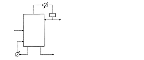
比較例1
図3のように、1機の蒸留塔を利用してn−ブチルアルデヒド及びiso−ブチルアルデヒドを分離した。蒸留塔の塔頂領域から流出される低沸点流れは、凝縮器を経て一部は蒸留塔に還流させ、残りの一部は、iso−ブチルアルデヒドを含む製品として生産した。蒸留塔の塔底領域から流出される流れは、再沸器を経て一部は蒸留塔に還流させ、残りの一部は、n−ブチルアルデヒドを含む製品に分離した。この場合、前記蒸留塔塔頂領域の運転圧力は、0.32Kg/cm2gに調節し、運転温度は、73℃に調節し、前記蒸留塔塔底領域の運転温度は、100℃となるように調節した。
比較例1の蒸留装置を使用してn−ブチルアルデヒド及びiso−ブチルアルデヒドを分離する場合のエネルギー使用量、回収量、節減量、節減率及びn−ブチルアルデヒド/iso−ブチルアルデヒド製品の純度を下記表2に示す。
Comparative Example 1
As shown in FIG. 3, n-butyraldehyde and iso-butyraldehyde were separated using a single distillation column. The low-boiling stream discharged from the top region of the distillation column was partially refluxed to the distillation column via a condenser, and the remaining part was produced as a product containing iso-butyraldehyde. The stream discharged from the bottom region of the distillation column was partly refluxed to the distillation column via a reboiler, and the remaining part was separated into a product containing n-butyraldehyde. In this case, the operating pressure in the top region of the distillation column is adjusted to 0.32 Kg / cm 2 g, the operating temperature is adjusted to 73 ° C., and the operating temperature in the bottom region of the distillation column is 100 ° C. Adjusted as follows.
Energy separation amount, recovery amount, saving amount, saving rate and purity of n-butyraldehyde / iso-butyraldehyde product when separating n-butyraldehyde and iso-butyraldehyde using the distillation apparatus of Comparative Example 1 It is shown in Table 2 below.
比較例2
前記第1蒸留塔及び第2蒸留塔の運転条件を下記表2のように変更したことを除いて、実施例1と同一の方法によってn−ブチルアルデヒド及びiso−ブチルアルデヒドを分離した。
比較例2の蒸留装置を使用してn−ブチルアルデヒド及びiso−ブチルアルデヒドを分離する場合のエネルギー使用量、回収量、節減量、節減率及びn−ブチルアルデヒド/iso−ブチルアルデヒド製品の純度を下記表2に示す。
Comparative Example 2
N-Butyraldehyde and iso-butyraldehyde were separated by the same method as in Example 1 except that the operating conditions of the first distillation column and the second distillation column were changed as shown in Table 2 below.
Energy separation amount, recovery amount, saving amount, saving rate and purity of n-butyraldehyde / iso-butyraldehyde product when separating n-butyraldehyde and iso-butyraldehyde using the distillation apparatus of Comparative Example 2 It is shown in Table 2 below.
比較例3
前記第1蒸留塔及び第2蒸留塔の運転条件を下記表2のように変更したことを除いて、実施例1と同一の方法によってn−ブチルアルデヒド及びiso−ブチルアルデヒドを分離した。
比較例3の蒸留装置を使用してn−ブチルアルデヒド及びiso−ブチルアルデヒドを分離する場合のエネルギー使用量、回収量、節減量、節減率及びn−ブチルアルデヒド/iso−ブチルアルデヒド製品の純度を下記表2に示す。
Comparative Example 3
N-Butyraldehyde and iso-butyraldehyde were separated by the same method as in Example 1 except that the operating conditions of the first distillation column and the second distillation column were changed as shown in Table 2 below.
Energy separation amount, recovery amount, saving amount, saving rate and purity of n-butyraldehyde / iso-butyraldehyde product when separating n-butyraldehyde and iso-butyraldehyde using the distillation apparatus of Comparative Example 3 It is shown in Table 2 below.
比較例4
前記第1蒸留塔及び第2蒸留塔の運転条件を下記表2のように変更したことを除いて、実施例1と同一の方法によってn−ブチルアルデヒド及びiso−ブチルアルデヒドを分離した。
比較例4の蒸留装置を使用してn−ブチルアルデヒド及びiso−ブチルアルデヒドを分離する場合のエネルギー使用量、回収量、節減量、節減率及びn−ブチルアルデヒド/iso−ブチルアルデヒド製品の純度を下記表2に示す。
Comparative Example 4
N-Butyraldehyde and iso-butyraldehyde were separated by the same method as in Example 1 except that the operating conditions of the first distillation column and the second distillation column were changed as shown in Table 2 below.
Energy separation amount, recovery amount, saving amount, saving rate and purity of n-butyraldehyde / iso-butyraldehyde product when separating n-butyraldehyde and iso-butyraldehyde using the distillation apparatus of Comparative Example 4 It is shown in Table 2 below.
比較例5
前記第1蒸留塔及び第2蒸留塔の運転条件を下記表3のように変更したことを除いて、実施例1と同一の方法によってn−ブチルアルデヒド及びiso−ブチルアルデヒドを分離した。
比較例5の蒸留装置を使用してn−ブチルアルデヒド及びiso−ブチルアルデヒドを分離する場合のエネルギー使用量、回収量、節減量、節減率及びn−ブチルアルデヒド/iso−ブチルアルデヒド製品の純度を下記表3に示す。
Comparative Example 5
N-Butyraldehyde and iso-butyraldehyde were separated by the same method as in Example 1 except that the operating conditions of the first distillation column and the second distillation column were changed as shown in Table 3 below.
Energy separation amount, recovery amount, saving amount, saving rate and purity of n-butyraldehyde / iso-butyraldehyde product when separating n-butyraldehyde and iso-butyraldehyde using the distillation apparatus of Comparative Example 5 Shown in Table 3 below.
比較例6
前記第1蒸留塔及び第2蒸留塔の運転条件を下記表3のように変更したことを除いて、実施例1と同一の方法によってn−ブチルアルデヒド及びiso−ブチルアルデヒドを分離した。
比較例6の蒸留装置を使用してn−ブチルアルデヒド及びiso−ブチルアルデヒドを分離する場合のエネルギー使用量、回収量、節減量、節減率及びn−ブチルアルデヒド/iso−ブチルアルデヒド製品の純度を下記表3に示す。
Comparative Example 6
N-Butyraldehyde and iso-butyraldehyde were separated by the same method as in Example 1 except that the operating conditions of the first distillation column and the second distillation column were changed as shown in Table 3 below.
Energy separation amount, recovery amount, saving amount, saving rate and purity of n-butyraldehyde / iso-butyraldehyde product when separating n-butyraldehyde and iso-butyraldehyde using the distillation apparatus of Comparative Example 6 Shown in Table 3 below.
比較例7
前記第1蒸留塔及び第2蒸留塔の運転条件を下記表3のように変更したことを除いて、実施例1と同一の方法によってn−ブチルアルデヒド及びiso−ブチルアルデヒドを分離した。
比較例7の蒸留装置を使用してn−ブチルアルデヒド及びiso−ブチルアルデヒドを分離する場合のエネルギー使用量、回収量、節減量、節減率及びn−ブチルアルデヒド/iso−ブチルアルデヒド製品の純度を下記表3に示す。
Comparative Example 7
N-Butyraldehyde and iso-butyraldehyde were separated by the same method as in Example 1 except that the operating conditions of the first distillation column and the second distillation column were changed as shown in Table 3 below.
Energy separation amount, recovery amount, saving amount, saving rate and purity of n-butyraldehyde / iso-butyraldehyde product when separating n-butyraldehyde and iso-butyraldehyde using the distillation apparatus of Comparative Example 7 Shown in Table 3 below.
比較例8
前記第1蒸留塔及び第2蒸留塔の運転条件を下記表3のように変更したことを除いて、実施例1と同一の方法によってn−ブチルアルデヒド及びiso−ブチルアルデヒドを分離した。
比較例8の蒸留装置を使用してn−ブチルアルデヒド及びiso−ブチルアルデヒドを分離する場合のエネルギー使用量、回収量、節減量、節減率及びn−ブチルアルデヒド/iso−ブチルアルデヒド製品の純度を下記表3に示す。
Comparative Example 8
N-Butyraldehyde and iso-butyraldehyde were separated by the same method as in Example 1 except that the operating conditions of the first distillation column and the second distillation column were changed as shown in Table 3 below.
Energy separation amount, recovery amount, saving amount, saving rate and purity of n-butyraldehyde / iso-butyraldehyde product when separating n-butyraldehyde and iso-butyraldehyde using the distillation apparatus of Comparative Example 8 Shown in Table 3 below.
前記表1〜表3に示されたように、実施例1〜5によってn−ブチルアルデヒドの異性質体を分離する場合、比較例に比べて総エネルギー消費量が大きく減少したことを確認することができる。したがって、本出願の実施例1〜5の蒸留装置によって原料を分離させる場合、比較例1の蒸留装置を使用した場合に比べて最大36.0%のエネルギー節減効果を得ることができることが分かる。 As shown in Tables 1 to 3, when isolating n-butyraldehyde isomers according to Examples 1 to 5, it was confirmed that the total energy consumption was greatly reduced as compared with Comparative Examples. Can do. Therefore, it can be seen that when the raw materials are separated by the distillation apparatuses of Examples 1 to 5 of the present application, an energy saving effect of up to 36.0% can be obtained as compared with the case where the distillation apparatus of Comparative Example 1 is used.
また、実施例及び比較例から分かるように、第1蒸留塔の塔底温度と第2蒸留塔の塔頂温度の差を特定範囲内に調節し、第1蒸留塔の塔頂領域の圧力と第2蒸留塔の塔頂領域の圧力を特定範囲内に調節することによって、高純度及び高効率でn−ブチルアルデヒド及びiso−ブチルアルデヒドを分離することができることを確認することができる。 Further, as can be seen from the Examples and Comparative Examples, the difference between the bottom temperature of the first distillation column and the top temperature of the second distillation column is adjusted within a specific range, and the pressure in the top region of the first distillation column is It can be confirmed that n-butyraldehyde and iso-butyraldehyde can be separated with high purity and high efficiency by adjusting the pressure in the top region of the second distillation column within a specific range.
また、比較例5及び6から分かるように、第1蒸留塔及び第2蒸留塔にそれぞれ流入される流量の比を特定範囲内に調節することによって、高純度及び高効率でn−ブチルアルデヒド及びiso−ブチルアルデヒドを分離することができることを確認することができる。 Further, as can be seen from Comparative Examples 5 and 6, by adjusting the ratio of the flow rate flowing into the first distillation column and the second distillation column within a specific range, n-butyraldehyde and high efficiency and high efficiency can be obtained. It can be confirmed that iso-butyraldehyde can be separated.
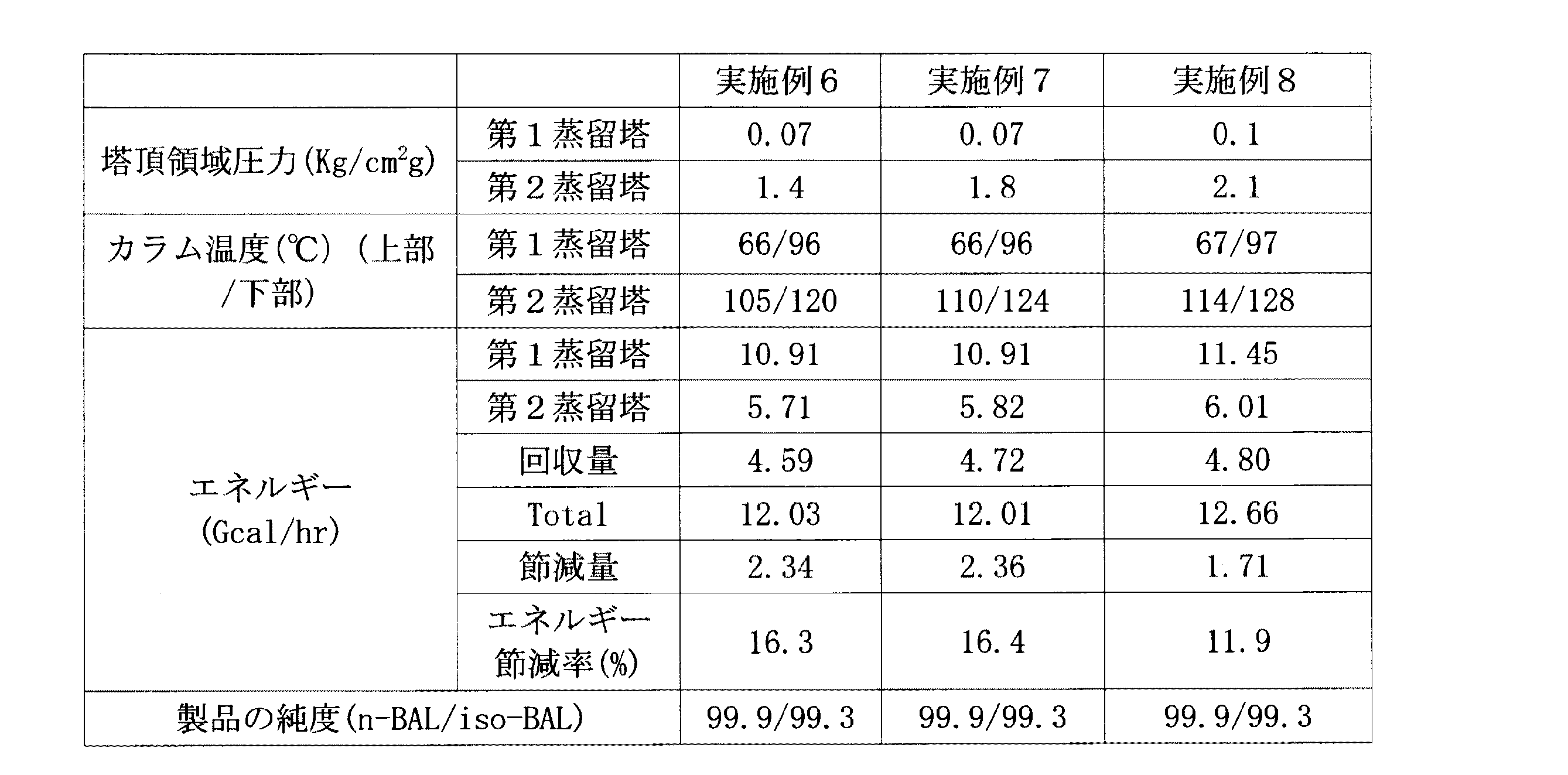
実施例6
図2の蒸留装置を使用してn−ブチルアルデヒド及びiso−ブチルアルデヒドを分離した。具体的には、n−ブチルアルデヒド及びiso−ブチルアルデヒドを含む原料を、理論段数が100段である第1蒸留塔に流入した。
Example 6
The distillation apparatus of FIG. 2 was used to separate n-butyraldehyde and iso-butyraldehyde. Specifically, a raw material containing n-butyraldehyde and iso-butyraldehyde was introduced into the first distillation column having 100 theoretical plates.
前記第1蒸留塔の塔頂領域から排出される第1塔頂流れの一部は、第1凝縮器を経て前記第1蒸留塔の塔頂領域に還流させた。前記第1塔頂流れの残りの一部は、iso−ブチルアルデヒドを含む製品に分離して貯蔵し、前記第1蒸留塔の塔底領域から排出される第1塔底流れは、第1再沸器を経て前記第1蒸留塔の塔底領域に還流させた。前記第1蒸留塔の塔底領域から流出される第2塔底流れは、第2蒸留塔に流入した。前記第1蒸留塔の塔底領域から流出される第3塔底流れは、熱交換器に流入させ、前記熱交換器に流入された第2蒸留塔の第2塔頂流れと熱交換させた後、前記熱交換器を経て第1蒸留塔の塔底領域に還流させた。この場合、前記第1蒸留塔塔頂領域の運転圧力を0.07Kg/cm2gに調節し、運転温度は、66℃に調節し、前記第1蒸留塔塔底領域の運転温度は、96℃となるように調節した。 A part of the first top stream discharged from the top region of the first distillation column was refluxed to the top region of the first distillation column via the first condenser. The remaining part of the first top stream is separated and stored in a product containing iso-butyraldehyde, and the first bottom stream discharged from the bottom region of the first distillation tower is the first recycle. The solution was refluxed to the bottom area of the first distillation column through a boiling machine. The second bottom stream flowing out from the bottom region of the first distillation column flowed into the second distillation column. The third bottom stream flowing out from the bottom region of the first distillation column was introduced into a heat exchanger, and heat exchange was performed with the second top stream of the second distillation column that was introduced into the heat exchanger. Thereafter, the mixture was refluxed to the bottom area of the first distillation column through the heat exchanger. In this case, the operating pressure in the top region of the first distillation column is adjusted to 0.07 Kg / cm 2 g, the operating temperature is adjusted to 66 ° C., and the operating temperature in the bottom region of the first distillation column is 96 It adjusted so that it might become ° C.
一方、前記第2蒸留塔の塔頂領域から排出される第2塔頂流れは、熱交換器に流入させ、前記第3塔底流れと熱交換させた後、前記熱交換器及び第2凝縮器を経て、一部は、前記第2蒸留塔の塔頂領域に還流させ、残りの一部は、n−ブチルアルデヒドを含む製品に分離した。この場合、n−ブチルアルデヒドの純度は、99.9%であった。前記第2蒸留塔の塔底領域から排出される第4塔底流れは、第2再沸器を経て前記第2蒸留塔の塔底領域に還流させ、前記第2蒸留塔の塔底領域から排出される第5塔底流れは、n−ブチルアルデヒドを含む製品に分離した。この場合、前記第2蒸留塔の塔頂領域の運転圧力は、1.4Kg/cm2gに調節し、運転温度は、105℃となるように調節し、前記第2蒸留塔の塔底領域の運転温度は、120℃となるように調節した。 On the other hand, the second tower top stream discharged from the top area of the second distillation tower flows into the heat exchanger and exchanges heat with the third tower bottom stream, and then the heat exchanger and the second condenser. Through the vessel, a part was refluxed to the top region of the second distillation column, and the remaining part was separated into a product containing n-butyraldehyde. In this case, the purity of n-butyraldehyde was 99.9%. The fourth bottom stream discharged from the bottom region of the second distillation column is refluxed to the bottom region of the second distillation column through a second reboiler, and from the bottom region of the second distillation column. The 5th bottom stream discharged is separated into a product containing n-butyraldehyde. In this case, the operating pressure in the top region of the second distillation column is adjusted to 1.4 Kg / cm 2 g, the operating temperature is adjusted to 105 ° C., and the bottom region of the second distillation column is adjusted. The operating temperature was adjusted to 120 ° C.
実施例6の蒸留装置を使用してn−ブチルアルデヒド及びiso−ブチルアルデヒドを分離する場合のエネルギー使用量、回収量、節減量、節減率及びn−ブチルアルデヒド/iso−ブチルアルデヒド製品の純度を下記表4に示す。 Energy separation amount, recovery amount, saving amount, saving rate and purity of n-butyraldehyde / iso-butyraldehyde product when separating n-butyraldehyde and iso-butyraldehyde using the distillation apparatus of Example 6 It is shown in Table 4 below.
実施例7
前記第1蒸留塔及び第2蒸留塔の運転条件を下記表3のように変更したことを除いて、実施例6と同一の方法によってn−ブチルアルデヒド及びiso−ブチルアルデヒドを分離した。
実施例7の蒸留装置を使用してn−ブチルアルデヒド及びiso−ブチルアルデヒドを分離する場合のエネルギー使用量、回収量、節減量、節減率及びn−ブチルアルデヒド/iso−ブチルアルデヒド製品の純度を下記表4に示す。
Example 7
N-Butyraldehyde and iso-butyraldehyde were separated by the same method as in Example 6 except that the operating conditions of the first distillation column and the second distillation column were changed as shown in Table 3 below.
Energy separation amount, recovery amount, saving amount, saving rate and purity of n-butyraldehyde / iso-butyraldehyde product when separating n-butyraldehyde and iso-butyraldehyde using the distillation apparatus of Example 7 It is shown in Table 4 below.
実施例8
前記第1蒸留塔及び第2蒸留塔の運転条件を下記表3のように変更したことを除いて、実施例6と同一の方法によってn−ブチルアルデヒド及びiso−ブチルアルデヒドを分離した。
実施例8の蒸留装置を使用してn−ブチルアルデヒド及びiso−ブチルアルデヒドを分離する場合のエネルギー使用量、回収量、節減量、節減率及びn−ブチルアルデヒド/iso−ブチルアルデヒド製品の純度を下記表4に示す。
Example 8
N-Butyraldehyde and iso-butyraldehyde were separated by the same method as in Example 6 except that the operating conditions of the first distillation column and the second distillation column were changed as shown in Table 3 below.
Energy separation amount, recovery amount, saving amount, saving rate and purity of n-butyraldehyde / iso-butyraldehyde product when separating n-butyraldehyde and iso-butyraldehyde using the distillation apparatus of Example 8 It is shown in Table 4 below.
比較例9
前記第1蒸留塔及び第2蒸留塔の運転条件を下記表5のように変更したことを除いて、実施例6と同一の方法によってn−ブチルアルデヒド及びiso−ブチルアルデヒドを分離した。
比較例9の蒸留装置を使用してn−ブチルアルデヒド及びiso−ブチルアルデヒドを分離する場合のエネルギー使用量、回収量、節減量、節減率及びn−ブチルアルデヒド/iso−ブチルアルデヒド製品の純度を下記表5に示す。
Comparative Example 9
N-Butyraldehyde and iso-butyraldehyde were separated by the same method as in Example 6 except that the operating conditions of the first distillation column and the second distillation column were changed as shown in Table 5 below.
Energy separation amount, recovery amount, saving amount, saving rate and purity of n-butyraldehyde / iso-butyraldehyde product when separating n-butyraldehyde and iso-butyraldehyde using the distillation apparatus of Comparative Example 9 It shows in Table 5 below.
比較例10
前記第1蒸留塔及び第2蒸留塔の運転条件を下記表5のように変更したことを除いて、実施例6と同一の方法によってn−ブチルアルデヒド及びiso−ブチルアルデヒドを分離した。
比較例10の蒸留装置を使用してn−ブチルアルデヒド及びiso−ブチルアルデヒドを分離する場合のエネルギー使用量、回収量、節減量、節減率及びn−ブチルアルデヒド/iso−ブチルアルデヒド製品の純度を下記表5に示す。
Comparative Example 10
N-Butyraldehyde and iso-butyraldehyde were separated by the same method as in Example 6 except that the operating conditions of the first distillation column and the second distillation column were changed as shown in Table 5 below.
Energy separation amount, recovery amount, saving amount, saving rate and purity of n-butyraldehyde / iso-butyraldehyde product when separating n-butyraldehyde and iso-butyraldehyde using the distillation apparatus of Comparative Example 10 It shows in Table 5 below.
比較例11
前記第1蒸留塔及び第2蒸留塔の運転条件を下記表5のように変更したことを除いて、実施例6と同一の方法によってn−ブチルアルデヒド及びiso−ブチルアルデヒドを分離した。
比較例11の蒸留装置を使用してn−ブチルアルデヒド及びiso−ブチルアルデヒドを分離する場合のエネルギー使用量、回収量、節減量、節減率及びn−ブチルアルデヒド/iso−ブチルアルデヒド製品の純度を下記表5に示す。
Comparative Example 11
N-Butyraldehyde and iso-butyraldehyde were separated by the same method as in Example 6 except that the operating conditions of the first distillation column and the second distillation column were changed as shown in Table 5 below.
Energy separation amount, recovery amount, saving amount, saving rate and purity of n-butyraldehyde / iso-butyraldehyde product when separating n-butyraldehyde and iso-butyraldehyde using the distillation apparatus of Comparative Example 11 It shows in Table 5 below.
比較例12
前記第1蒸留塔及び第2蒸留塔の運転条件を下記表6のように変更したことを除いて、実施例6と同一の方法によってn−ブチルアルデヒド及びiso−ブチルアルデヒドを分離した。
比較例12の蒸留装置を使用してn−ブチルアルデヒド及びiso−ブチルアルデヒドを分離する場合のエネルギー使用量、回収量、節減量、節減率及びn−ブチルアルデヒド/iso−ブチルアルデヒド製品の純度を下記表6に示す。
Comparative Example 12
N-Butyraldehyde and iso-butyraldehyde were separated by the same method as in Example 6 except that the operating conditions of the first distillation column and the second distillation column were changed as shown in Table 6 below.
Energy separation amount, recovery amount, saving amount, saving rate and purity of n-butyraldehyde / iso-butyraldehyde product when separating n-butyraldehyde and iso-butyraldehyde using the distillation apparatus of Comparative Example 12 It is shown in Table 6 below.
比較例13
前記第1蒸留塔及び第2蒸留塔の運転条件を下記表6のように変更したことを除いて、実施例6と同一の方法によってn−ブチルアルデヒド及びiso−ブチルアルデヒドを分離した。
比較例13の蒸留装置を使用してn−ブチルアルデヒド及びiso−ブチルアルデヒドを分離する場合のエネルギー使用量、回収量、節減量、節減率及びn−ブチルアルデヒド/iso−ブチルアルデヒド製品の純度を下記表6に示す。
Comparative Example 13
N-Butyraldehyde and iso-butyraldehyde were separated by the same method as in Example 6 except that the operating conditions of the first distillation column and the second distillation column were changed as shown in Table 6 below.
Energy separation amount, recovery amount, saving amount, saving rate and purity of n-butyraldehyde / iso-butyraldehyde product when separating n-butyraldehyde and iso-butyraldehyde using the distillation apparatus of Comparative Example 13 It is shown in Table 6 below.
前記表4〜表6に示されたように、実施例6〜8によってn−ブチルアルデヒドの異性質体を分離する場合、比較例に比べて総エネルギー消費量が大きく減少したことを確認することができる。したがって、本出願の実施例6〜8の蒸留装置によって原料を分離させる場合、比較例5の蒸留装置を使用した場合に比べて最大16.4%のエネルギー節減効果を得ることができることが分かる。 As shown in Tables 4 to 6, when the isomers of n-butyraldehyde were separated according to Examples 6 to 8, it was confirmed that the total energy consumption was greatly reduced compared to the comparative examples. Can do. Therefore, it can be seen that when the raw materials are separated by the distillation apparatuses of Examples 6 to 8 of the present application, an energy saving effect of up to 16.4% can be obtained as compared with the case where the distillation apparatus of Comparative Example 5 is used.
また、実施例及び比較例から分かるように、第1蒸留塔の塔底温度と第2蒸留塔の塔頂温度の差を特定範囲内に調節し、第1蒸留塔の塔頂領域の圧力と第2蒸留塔の塔頂領域の圧力を特定範囲内に調節することによって、高純度及び高効率でn−ブチルアルデヒドを分離し得ることを確認することができる。 Further, as can be seen from the Examples and Comparative Examples, the difference between the bottom temperature of the first distillation column and the top temperature of the second distillation column is adjusted within a specific range, and the pressure in the top region of the first distillation column is It can be confirmed that n-butyraldehyde can be separated with high purity and high efficiency by adjusting the pressure in the top region of the second distillation column within a specific range.
Claims (21)
下記化学式1の化合物及び前記化合物の異性体を含む原料が前記第1蒸留塔の第1供給ポート及び/または第2蒸留塔の第2供給ポートに流入され、
前記第1蒸留塔の第1供給ポートに流入された原料は、前記第1蒸留塔の塔頂領域から流出される第1塔頂流れ;及び前記第1蒸留塔の塔底領域から流出される第1塔底流れ、第2塔底流れ及び第3塔底流れとにそれぞれ分離して流出され、
前記第1塔頂流れは、前記第1凝縮器に流入され、前記第1凝縮器を通過した第1塔頂流れの一部または全部は、前記第1蒸留塔の塔頂領域に還流され、
前記第1塔底流れは、前記第1再沸器に流入され、前記第1再沸器を通過した第1塔底流れは、前記第1蒸留塔の塔底領域に還流され、
前記第2蒸留塔の第2供給ポートに流入される流れは、前記第2蒸留塔の塔頂領域から流出される第2塔頂流れ;前記第2蒸留塔の塔底領域から流出される第4塔底流れ及び第5塔底流れとにそれぞれ分離して流出され、
前記第4塔底流れは、前記第2再沸器に流入され、前記第2再沸器を通過した第4塔底流れは、前記第2蒸留塔の塔底領域に還流され、
前記第3塔底流れ及び第2塔頂流れは、前記熱交換器に流入されて熱交換され、前記熱交換器を通過した第3塔底流れは、第1蒸留塔の塔底領域に還流され、前記熱交換器を通過した第2塔頂流れは、第2凝縮器に流入され、前記第2凝縮器を通過した第2塔頂流れの一部または全部は、前記第2蒸留塔の塔頂領域に還流され、
下記一般式1及び下記一般式2を満足する蒸留装置:
[一般式1]
Tt-2−Tb-3≧8℃
[一般式2]
P2/P1≧20
前記一般式1で、Tt-2は、第2塔頂流れの温度を示し、Tb-3は、第3塔底流れの温度を示し、
前記一般式2で、P1は、第1蒸留塔の塔頂領域の圧力(Kg/cm2g)を示し、P2は、第2蒸留塔の塔頂領域の圧力(Kg/cm2g)を示す。 A first distillation unit comprising a first condenser, a first reboiler and a first distillation column; a second distillation unit comprising a second condenser, a second reboiler and a second distillation column; and a heat exchanger ,
A raw material containing a compound of the following chemical formula 1 and an isomer of the compound is introduced into the first supply port of the first distillation column and / or the second supply port of the second distillation column,
The raw material that has flowed into the first supply port of the first distillation column flows out of the first column top flow that flows out from the column top region of the first distillation column; and the column bottom region of the first distillation column. The first bottom stream, the second bottom stream, and the third bottom stream are separated and discharged,
The first column top stream is introduced into the first condenser, and a part or all of the first column top stream that has passed through the first condenser is refluxed to the column top region of the first distillation column,
The first bottom stream is introduced into the first reboiler, and the first bottom stream that has passed through the first reboiler is refluxed to the bottom region of the first distillation tower,
The flow flowing into the second feed port of the second distillation column is a second tower top flow that flows out from the top region of the second distillation column; a second flow that flows out from the bottom region of the second distillation column. Separated into 4 tower bottom stream and 5th tower bottom stream,
The fourth bottom stream is introduced into the second reboiler, and the fourth bottom stream that has passed through the second reboiler is refluxed to the bottom region of the second distillation tower;
The third tower bottom stream and the second tower top stream are introduced into the heat exchanger and heat exchanged, and the third tower bottom stream passing through the heat exchanger is returned to the tower bottom region of the first distillation tower. The second overhead stream that has passed through the heat exchanger is introduced into a second condenser, and a part or all of the second overhead stream that has passed through the second condenser is part of the second distillation tower. Refluxed to the top area,
A distillation apparatus satisfying the following general formula 1 and the following general formula 2:
[General Formula 1]
T t-2 -T b-3 ≧ 8 ℃
[General formula 2]
P 2 / P 1 ≧ 20
In the general formula 1, T t-2 represents the temperature of the second column top stream, T b-3 represents the temperature of the third column bottom stream,
In Formula 2, P 1 denotes the pressure in the overhead area of the first distillation column (Kg / cm 2 g), P 2 is the pressure of column top region of the second distillation column (Kg / cm 2 g ).
第1塔頂流れ及び第2塔頂流れ内の前記iso−ブチルアルデヒドの含量が90%以上であり、第2塔底流れ及び第5塔底流れ内の前記n−ブチルアルデヒドの含量が90%以上である、請求項2に記載の蒸留装置。 The compound of Formula 1 is n-butyraldehyde, and the isomer of the compound is iso-butyraldehyde,
The iso-butyraldehyde content in the first overhead stream and the second overhead stream is 90% or more, and the n-butyraldehyde content in the second bottom stream and the fifth bottom stream is 90%. It is the above, The distillation apparatus of Claim 2.
[一般式3]
0.3≦F1/F2≦3.0
前記一般式3で、F1は、第1蒸留塔の第1供給ポートに流入される原料の流量(ton/hr)を示し、F2は、第2蒸留塔の第2供給ポートにそれぞれ流入される原料の流量(ton/hr)を示す。 The distillation apparatus according to claim 2, which satisfies the following general formula 3:
[General formula 3]
0.3 ≦ F 1 / F 2 ≦ 3.0
In Formula 3, F 1 indicates the flow rate (ton / hr) of the raw material flowing into the first supply port of the first distillation column, and F 2 flows into the second supply port of the second distillation column. The flow rate (ton / hr) of the raw material is shown.
第1塔頂流れ内の前記iso−ブチルアルデヒドの含量が90%以上であり、第2塔頂流れ内の前記n−ブチルアルデヒドの含量が90%以上である、請求項11に記載の蒸留装置。 The compound of Formula 1 is n-butyraldehyde, and the isomer of the compound is iso-butyraldehyde,
The distillation apparatus according to claim 11, wherein the content of the iso-butyraldehyde in the first overhead stream is 90% or more and the content of the n-butyraldehyde in the second overhead stream is 90% or more. .
前記第1供給ポートに流入された原料を前記第1蒸留塔の塔頂領域から流出される第1塔頂流れ;並びに前記第1蒸留塔の塔底領域から流出される第1塔底流れ、第2塔底流れ及び第3塔底流れにそれぞれ流出させる段階;
前記第2供給ポートに流入された原料を、前記第2蒸留塔の塔頂領域から流出される第2塔頂流れ;並びに前記第2蒸留塔の塔底領域から流出される第4塔底流れ及び第5塔底流れにそれぞれ流出させる段階;
前記第2塔頂流れと前記第3塔底流れを熱交換させる段階;及び
前記第1蒸留塔の塔底領域で前記化学式1の化合物を分離し、前記第1蒸留塔の塔頂領域及び第2蒸留塔の塔頂領域で前記化学式1の化合物の異性体を分離する段階を含み、
下記一般式1及び2を満足する化学式1の化合物の製造方法:
[一般式1]
Tt-2−Tb-3≧8℃
[一般式2]
P2/P1≧20
前記一般式1で、Tt-2は、第2塔頂流れの温度を示し、Tb-3は、第3塔底流れの温度を示し、
前記一般式2で、P1は、第1蒸留塔の塔頂領域の圧力(Kg/cm2g)を示し、P2は、第2蒸留塔の塔頂領域の圧力(Kg/cm2g)を示す。 Flowing a raw material containing a compound of the following formula 1 and an isomer of the compound into the first supply port of the first distillation column and the second supply port of the second distillation column;
A first column top stream that flows out of the raw material that has flowed into the first supply port from a column top region of the first distillation column; and a first column bottom stream that flows out from the column bottom region of the first distillation column; Flowing into the second bottom stream and the third bottom stream, respectively;
A second column top stream flowing out from the column top region of the second distillation column, and a fourth column bottom stream flowing out from the column bottom region of the second distillation column. And letting it flow into the bottom column stream, respectively;
Heat-exchanging the second column top stream and the third column bottom stream; and separating the compound of Formula 1 in a column bottom region of the first distillation column; 2 separating the isomers of the compound of Formula 1 in the top region of the distillation column,
Method for producing compound of formula 1 satisfying the following general formulas 1 and 2:
[General Formula 1]
T t-2 -T b-3 ≧ 8 ℃
[General formula 2]
P 2 / P 1 ≧ 20
In the general formula 1, T t-2 represents the temperature of the second column top stream, T b-3 represents the temperature of the third column bottom stream,
In Formula 2, P 1 denotes the pressure in the overhead area of the first distillation column (Kg / cm 2 g), P 2 is the pressure of column top region of the second distillation column (Kg / cm 2 g ).
前記流入された原料を前記第1蒸留塔の塔頂領域から流出される第1塔頂流れ;並びに前記第1蒸留塔の塔底領域から流出される第1塔底流れ、第2塔底流れ及び第3塔底流れにそれぞれ流出させる段階;
前記第1塔底流れを第2蒸留塔の第2供給ポートに流入させる段階;
前記第2供給ポートに流入された流れを、前記第2蒸留塔の塔頂領域から流出される第2塔頂流れ;並びに前記第2蒸留塔の塔底領域から流出される第4塔底流れ及び第5塔底流れにそれぞれ流出させる段階;
前記第2塔頂流れと前記第3塔底流れを熱交換させる段階;及び
第2蒸留塔の塔頂領域で前記化学式1の化合物を分離し、前記第1蒸留塔の塔頂領域で化合物の異性体を分離する段階を含み、
下記一般式1及び下記一般式2を満足する化学式1の化合物の製造方法:
[一般式1]
Tt-2−Tb-3≧8℃
[一般式2]
P2/P1≧20
前記一般式1で、Tt-2は、第2塔頂流れの温度を示し、Tb-3は、第3塔底流れの温度を示し、
前記一般式2で、P1は、第1蒸留塔の塔頂領域の圧力(Kg/cm2g)を示し、P2は、第2蒸留塔の塔頂領域の圧力(Kg/cm2g)を示す。 Flowing a raw material containing a compound of the following formula 1 and an isomer of the compound into the first supply port of the first distillation column;
A first tower top stream that flows out the introduced raw material from a tower top area of the first distillation tower; and a first tower bottom stream and a second tower bottom stream that flow out from the tower bottom area of the first distillation tower. And letting it flow into the third tower bottom stream, respectively;
Flowing the first bottom stream into a second feed port of a second distillation column;
The flow that has flowed into the second supply port is divided into a second column top flow that flows out from the column top region of the second distillation column; and a fourth column bottom flow that flows out from the column bottom region of the second distillation column. And letting it flow into the bottom column stream, respectively;
Heat-exchanging the second column top stream and the third column bottom stream; and separating the compound of Formula 1 in a column top region of the second distillation column; Separating the isomers,
Production method of compound of chemical formula 1 satisfying the following general formula 1 and the following general formula 2:
[General Formula 1]
T t-2 -T b-3 ≧ 8 ℃
[General formula 2]
P 2 / P 1 ≧ 20
In the general formula 1, T t-2 represents the temperature of the second column top stream, T b-3 represents the temperature of the third column bottom stream,
In Formula 2, P 1 denotes the pressure in the overhead area of the first distillation column (Kg / cm 2 g), P 2 is the pressure of column top region of the second distillation column (Kg / cm 2 g ).
Applications Claiming Priority (5)
| Application Number | Priority Date | Filing Date | Title |
|---|---|---|---|
| KR10-2014-0150416 | 2014-10-31 | ||
| KR20140150416 | 2014-10-31 | ||
| PCT/KR2015/011651 WO2016068676A1 (en) | 2014-10-31 | 2015-11-02 | Distillation apparatus |
| KR10-2015-0153090 | 2015-11-02 | ||
| KR1020150153090A KR101792347B1 (en) | 2014-10-31 | 2015-11-02 | Distillation device |
Publications (2)
| Publication Number | Publication Date |
|---|---|
| JP2017534603A true JP2017534603A (en) | 2017-11-24 |
| JP6487543B2 JP6487543B2 (en) | 2019-03-20 |
Family
ID=56024835
Family Applications (1)
| Application Number | Title | Priority Date | Filing Date |
|---|---|---|---|
| JP2017518463A Active JP6487543B2 (en) | 2014-10-31 | 2015-11-02 | Distillation equipment |
Country Status (5)
| Country | Link |
|---|---|
| US (1) | US20170333808A1 (en) |
| EP (1) | EP3214062B1 (en) |
| JP (1) | JP6487543B2 (en) |
| KR (1) | KR101792347B1 (en) |
| CN (1) | CN107106922B (en) |
Cited By (2)
| Publication number | Priority date | Publication date | Assignee | Title |
|---|---|---|---|---|
| JP2019500214A (en) * | 2016-09-13 | 2019-01-10 | エルジー・ケム・リミテッド | Selective distillation apparatus and distillation method |
| WO2019151710A1 (en) * | 2018-02-01 | 2019-08-08 | 주식회사 엘지화학 | Method for producing dimethylolbutanal and distillation apparatus |
Families Citing this family (6)
| Publication number | Priority date | Publication date | Assignee | Title |
|---|---|---|---|---|
| KR102387634B1 (en) * | 2017-06-08 | 2022-04-19 | 주식회사 엘지화학 | Fraction device and method for fraction thereof |
| JP7101813B2 (en) * | 2018-11-01 | 2022-07-15 | エルジー・ケム・リミテッド | Method of separating an organic solvent from a mixed solution containing an organic solvent |
| KR102474740B1 (en) * | 2018-12-18 | 2022-12-05 | 주식회사 엘지화학 | Process for recovering amide compounds |
| CN116020151B (en) * | 2021-10-27 | 2025-09-09 | 南京安立格有限公司 | Energy-saving and carbon-reducing mixed butyraldehyde separation system and separation method |
| CN115120997A (en) * | 2022-06-30 | 2022-09-30 | 浙江卫星能源有限公司 | Separation system and method for n-butyraldehyde and isobutyraldehyde |
| KR102550716B1 (en) * | 2022-11-24 | 2023-06-30 | 부경대학교 산학협력단 | Bio-jet separation equipment and separation method with high energy efficiency by diabatic distillation |
Citations (7)
| Publication number | Priority date | Publication date | Assignee | Title |
|---|---|---|---|---|
| JPS53112803A (en) * | 1977-03-11 | 1978-10-02 | Ici Ltd | Method of rectfying methanol |
| JPS5885828A (en) * | 1981-11-04 | 1983-05-23 | ヘキスト・アクチエンゲゼルシヤフト | Continuous purification of alcohol-containing liquid mixture |
| JPS58183634A (en) * | 1982-04-19 | 1983-10-26 | Tsukishima Kikai Co Ltd | Production of anhydrous ethanol through multiple effect process |
| JPS62273922A (en) * | 1986-05-23 | 1987-11-28 | Mitsui Toatsu Chem Inc | Method for purifying 1,2-dichloroethane |
| JPH0840967A (en) * | 1994-07-29 | 1996-02-13 | Mitsubishi Chem Corp | Method for producing high-purity isoaldehyde |
| JPH0840966A (en) * | 1994-07-29 | 1996-02-13 | Mitsubishi Chem Corp | Method for producing high-purity isoaldehyde |
| JP2005103407A (en) * | 2003-09-30 | 2005-04-21 | New Energy & Industrial Technology Development Organization | Heat exchange apparatus using tower top vapor and tower bottom liquid and heat exchange method thereof |
Family Cites Families (7)
| Publication number | Priority date | Publication date | Assignee | Title |
|---|---|---|---|---|
| US5865957A (en) * | 1994-12-01 | 1999-02-02 | Mitsubishi Chemical Company | Method for producing butyraldehydes |
| RU2130917C1 (en) * | 1997-09-10 | 1999-05-27 | Открытое акционерное общество "Салаватнефтеоргсинтез" | METHOD OF ISOLATING n-BUTYRIC ALDEHYDE FROM PROPYLENE HYDROFORMYLATION PRODUCT |
| DE19914259A1 (en) * | 1999-03-29 | 2000-10-05 | Basf Ag | Process for the separation by distillation of a liquid crude aldehyde mixture |
| US6765113B2 (en) * | 2000-07-19 | 2004-07-20 | E.I. Du Pont De Nemours And Company | Production of aromatic carboxylic acids |
| KR101686277B1 (en) * | 2012-05-31 | 2016-12-13 | 주식회사 엘지화학 | Manufacturing device for alkanol |
| JP6238148B2 (en) * | 2013-08-01 | 2017-11-29 | エルジー・ケム・リミテッド | Purification apparatus and purification method using the same |
| KR101804637B1 (en) * | 2014-10-31 | 2018-01-10 | 주식회사 엘지화학 | Distillation device |
-
2015
- 2015-11-02 US US15/518,397 patent/US20170333808A1/en not_active Abandoned
- 2015-11-02 JP JP2017518463A patent/JP6487543B2/en active Active
- 2015-11-02 EP EP15854890.9A patent/EP3214062B1/en active Active
- 2015-11-02 CN CN201580058865.6A patent/CN107106922B/en active Active
- 2015-11-02 KR KR1020150153090A patent/KR101792347B1/en active Active
Patent Citations (7)
| Publication number | Priority date | Publication date | Assignee | Title |
|---|---|---|---|---|
| JPS53112803A (en) * | 1977-03-11 | 1978-10-02 | Ici Ltd | Method of rectfying methanol |
| JPS5885828A (en) * | 1981-11-04 | 1983-05-23 | ヘキスト・アクチエンゲゼルシヤフト | Continuous purification of alcohol-containing liquid mixture |
| JPS58183634A (en) * | 1982-04-19 | 1983-10-26 | Tsukishima Kikai Co Ltd | Production of anhydrous ethanol through multiple effect process |
| JPS62273922A (en) * | 1986-05-23 | 1987-11-28 | Mitsui Toatsu Chem Inc | Method for purifying 1,2-dichloroethane |
| JPH0840967A (en) * | 1994-07-29 | 1996-02-13 | Mitsubishi Chem Corp | Method for producing high-purity isoaldehyde |
| JPH0840966A (en) * | 1994-07-29 | 1996-02-13 | Mitsubishi Chem Corp | Method for producing high-purity isoaldehyde |
| JP2005103407A (en) * | 2003-09-30 | 2005-04-21 | New Energy & Industrial Technology Development Organization | Heat exchange apparatus using tower top vapor and tower bottom liquid and heat exchange method thereof |
Cited By (3)
| Publication number | Priority date | Publication date | Assignee | Title |
|---|---|---|---|---|
| JP2019500214A (en) * | 2016-09-13 | 2019-01-10 | エルジー・ケム・リミテッド | Selective distillation apparatus and distillation method |
| WO2019151710A1 (en) * | 2018-02-01 | 2019-08-08 | 주식회사 엘지화학 | Method for producing dimethylolbutanal and distillation apparatus |
| US10913700B2 (en) | 2018-02-01 | 2021-02-09 | Lg Chem, Ltd. | Method for producing dimethylolbutanal and distillation apparatus for producing same |
Also Published As
| Publication number | Publication date |
|---|---|
| US20170333808A1 (en) | 2017-11-23 |
| EP3214062B1 (en) | 2020-01-08 |
| CN107106922B (en) | 2020-02-18 |
| KR20160052416A (en) | 2016-05-12 |
| JP6487543B2 (en) | 2019-03-20 |
| EP3214062A4 (en) | 2018-06-27 |
| CN107106922A (en) | 2017-08-29 |
| EP3214062A1 (en) | 2017-09-06 |
| KR101792347B1 (en) | 2017-11-01 |
Similar Documents
| Publication | Publication Date | Title |
|---|---|---|
| JP6487543B2 (en) | Distillation equipment | |
| JP6450454B2 (en) | Distillation equipment | |
| CN104968636B (en) | For preparing the device of alkanol | |
| JP6518233B2 (en) | Method and apparatus for the separation of ternary or multicomponent mixtures by distillation | |
| CN109053355B (en) | Method for purifying biphenyl by continuous rectification | |
| JP2020522376A (en) | Distillation apparatus and distillation method | |
| CN105566030A (en) | Method for separating BTX | |
| CN103508847B (en) | A kind of method of high-purity butanols of butanols dewatering and recovery and device | |
| CN205649873U (en) | Refining plant of trimellitic acid acid anhydride | |
| CN202315370U (en) | Energy-saving device used in catalytic reaction rectifying process | |
| CN209338419U (en) | A kind of cyclohexene production energy-saving system | |
| KR102454907B1 (en) | Apparatus for distillation and distillation method | |
| CN106187707B (en) | Process for producing alkylphenol | |
| KR20130135118A (en) | Purification device for alkanol | |
| CN115589781A (en) | Method for preparing isopropanol | |
| CN219355281U (en) | Heat exchange mechanism of cyclohexene tertiary extraction, rectification and separation equipment | |
| CN223069481U (en) | Separation and purification system for synthesizing propargyl alcohol | |
| CN103450101B (en) | Continuous purification process of methylbenzotriazole | |
| KR101686277B1 (en) | Manufacturing device for alkanol | |
| CN113173831B (en) | Production system and process for continuous chlorination of trichlorotoluene | |
| KR101569239B1 (en) | Menufacturing device for alkanol | |
| KR101569238B1 (en) | Menufacturing device for alkanol | |
| KR101569240B1 (en) | Manufacturing device for alkanol | |
| CN116272736A (en) | A kind of continuous production method of diethyl maleate | |
| KR20130135116A (en) | Manufacturing device for alkanol |
Legal Events
| Date | Code | Title | Description |
|---|---|---|---|
| A621 | Written request for application examination |
Free format text: JAPANESE INTERMEDIATE CODE: A621 Effective date: 20170925 |
|
| A977 | Report on retrieval |
Free format text: JAPANESE INTERMEDIATE CODE: A971007 Effective date: 20180723 |
|
| A131 | Notification of reasons for refusal |
Free format text: JAPANESE INTERMEDIATE CODE: A131 Effective date: 20180726 |
|
| A521 | Request for written amendment filed |
Free format text: JAPANESE INTERMEDIATE CODE: A523 Effective date: 20181001 |
|
| TRDD | Decision of grant or rejection written | ||
| A01 | Written decision to grant a patent or to grant a registration (utility model) |
Free format text: JAPANESE INTERMEDIATE CODE: A01 Effective date: 20190124 |
|
| A61 | First payment of annual fees (during grant procedure) |
Free format text: JAPANESE INTERMEDIATE CODE: A61 Effective date: 20190221 |
|
| R150 | Certificate of patent or registration of utility model |
Ref document number: 6487543 Country of ref document: JP Free format text: JAPANESE INTERMEDIATE CODE: R150 |
|
| R250 | Receipt of annual fees |
Free format text: JAPANESE INTERMEDIATE CODE: R250 |
|
| R250 | Receipt of annual fees |
Free format text: JAPANESE INTERMEDIATE CODE: R250 |
|
| R250 | Receipt of annual fees |
Free format text: JAPANESE INTERMEDIATE CODE: R250 |
|
| R250 | Receipt of annual fees |
Free format text: JAPANESE INTERMEDIATE CODE: R250 |
|
| R250 | Receipt of annual fees |
Free format text: JAPANESE INTERMEDIATE CODE: R250 |