JP2017529665A - Fabric-friendly secondary battery package - Google Patents
Fabric-friendly secondary battery package Download PDFInfo
- Publication number
- JP2017529665A JP2017529665A JP2017511930A JP2017511930A JP2017529665A JP 2017529665 A JP2017529665 A JP 2017529665A JP 2017511930 A JP2017511930 A JP 2017511930A JP 2017511930 A JP2017511930 A JP 2017511930A JP 2017529665 A JP2017529665 A JP 2017529665A
- Authority
- JP
- Japan
- Prior art keywords
- battery package
- layer
- battery
- package according
- velcro
- Prior art date
- Legal status (The legal status is an assumption and is not a legal conclusion. Google has not performed a legal analysis and makes no representation as to the accuracy of the status listed.)
- Granted
Links
Images


Classifications
-
- A—HUMAN NECESSITIES
- A42—HEADWEAR
- A42B—HATS; HEAD COVERINGS
- A42B1/00—Hats; Caps; Hoods
- A42B1/24—Hats; Caps; Hoods with means for attaching articles thereto, e.g. memorandum tablets or mirrors
-
- H—ELECTRICITY
- H01—ELECTRIC ELEMENTS
- H01M—PROCESSES OR MEANS, e.g. BATTERIES, FOR THE DIRECT CONVERSION OF CHEMICAL ENERGY INTO ELECTRICAL ENERGY
- H01M50/00—Constructional details or processes of manufacture of the non-active parts of electrochemical cells other than fuel cells, e.g. hybrid cells
- H01M50/10—Primary casings, jackets or wrappings of a single cell or a single battery
-
- A—HUMAN NECESSITIES
- A41—WEARING APPAREL
- A41D—OUTERWEAR; PROTECTIVE GARMENTS; ACCESSORIES
- A41D1/00—Garments
- A41D1/002—Garments adapted to accommodate electronic equipment
-
- A—HUMAN NECESSITIES
- A43—FOOTWEAR
- A43B—CHARACTERISTIC FEATURES OF FOOTWEAR; PARTS OF FOOTWEAR
- A43B3/00—Footwear characterised by the shape or the use
- A43B3/34—Footwear characterised by the shape or the use with electrical or electronic arrangements
-
- H—ELECTRICITY
- H01—ELECTRIC ELEMENTS
- H01B—CABLES; CONDUCTORS; INSULATORS; SELECTION OF MATERIALS FOR THEIR CONDUCTIVE, INSULATING OR DIELECTRIC PROPERTIES
- H01B1/00—Conductors or conductive bodies characterised by the conductive materials; Selection of materials as conductors
- H01B1/06—Conductors or conductive bodies characterised by the conductive materials; Selection of materials as conductors mainly consisting of other non-metallic substances
-
- H—ELECTRICITY
- H01—ELECTRIC ELEMENTS
- H01M—PROCESSES OR MEANS, e.g. BATTERIES, FOR THE DIRECT CONVERSION OF CHEMICAL ENERGY INTO ELECTRICAL ENERGY
- H01M10/00—Secondary cells; Manufacture thereof
- H01M10/42—Methods or arrangements for servicing or maintenance of secondary cells or secondary half-cells
- H01M10/425—Structural combination with electronic components, e.g. electronic circuits integrated to the outside of the casing
-
- H—ELECTRICITY
- H01—ELECTRIC ELEMENTS
- H01M—PROCESSES OR MEANS, e.g. BATTERIES, FOR THE DIRECT CONVERSION OF CHEMICAL ENERGY INTO ELECTRICAL ENERGY
- H01M50/00—Constructional details or processes of manufacture of the non-active parts of electrochemical cells other than fuel cells, e.g. hybrid cells
- H01M50/10—Primary casings, jackets or wrappings of a single cell or a single battery
- H01M50/147—Lids or covers
-
- H—ELECTRICITY
- H01—ELECTRIC ELEMENTS
- H01M—PROCESSES OR MEANS, e.g. BATTERIES, FOR THE DIRECT CONVERSION OF CHEMICAL ENERGY INTO ELECTRICAL ENERGY
- H01M50/00—Constructional details or processes of manufacture of the non-active parts of electrochemical cells other than fuel cells, e.g. hybrid cells
- H01M50/20—Mountings; Secondary casings or frames; Racks, modules or packs; Suspension devices; Shock absorbers; Transport or carrying devices; Holders
- H01M50/296—Mountings; Secondary casings or frames; Racks, modules or packs; Suspension devices; Shock absorbers; Transport or carrying devices; Holders characterised by terminals of battery packs
-
- H—ELECTRICITY
- H01—ELECTRIC ELEMENTS
- H01M—PROCESSES OR MEANS, e.g. BATTERIES, FOR THE DIRECT CONVERSION OF CHEMICAL ENERGY INTO ELECTRICAL ENERGY
- H01M50/00—Constructional details or processes of manufacture of the non-active parts of electrochemical cells other than fuel cells, e.g. hybrid cells
- H01M50/50—Current conducting connections for cells or batteries
- H01M50/531—Electrode connections inside a battery casing
-
- H—ELECTRICITY
- H01—ELECTRIC ELEMENTS
- H01M—PROCESSES OR MEANS, e.g. BATTERIES, FOR THE DIRECT CONVERSION OF CHEMICAL ENERGY INTO ELECTRICAL ENERGY
- H01M50/00—Constructional details or processes of manufacture of the non-active parts of electrochemical cells other than fuel cells, e.g. hybrid cells
- H01M50/50—Current conducting connections for cells or batteries
- H01M50/543—Terminals
- H01M50/547—Terminals characterised by the disposition of the terminals on the cells
- H01M50/55—Terminals characterised by the disposition of the terminals on the cells on the same side of the cell
-
- H—ELECTRICITY
- H01—ELECTRIC ELEMENTS
- H01M—PROCESSES OR MEANS, e.g. BATTERIES, FOR THE DIRECT CONVERSION OF CHEMICAL ENERGY INTO ELECTRICAL ENERGY
- H01M50/00—Constructional details or processes of manufacture of the non-active parts of electrochemical cells other than fuel cells, e.g. hybrid cells
- H01M50/50—Current conducting connections for cells or batteries
- H01M50/543—Terminals
- H01M50/552—Terminals characterised by their shape
- H01M50/553—Terminals adapted for prismatic, pouch or rectangular cells
-
- E—FIXED CONSTRUCTIONS
- E04—BUILDING
- E04H—BUILDINGS OR LIKE STRUCTURES FOR PARTICULAR PURPOSES; SWIMMING OR SPLASH BATHS OR POOLS; MASTS; FENCING; TENTS OR CANOPIES, IN GENERAL
- E04H15/00—Tents or canopies, in general
- E04H15/02—Tents combined or specially associated with other devices
-
- H—ELECTRICITY
- H01—ELECTRIC ELEMENTS
- H01M—PROCESSES OR MEANS, e.g. BATTERIES, FOR THE DIRECT CONVERSION OF CHEMICAL ENERGY INTO ELECTRICAL ENERGY
- H01M2220/00—Batteries for particular applications
- H01M2220/30—Batteries in portable systems, e.g. mobile phone, laptop
-
- H—ELECTRICITY
- H01—ELECTRIC ELEMENTS
- H01M—PROCESSES OR MEANS, e.g. BATTERIES, FOR THE DIRECT CONVERSION OF CHEMICAL ENERGY INTO ELECTRICAL ENERGY
- H01M50/00—Constructional details or processes of manufacture of the non-active parts of electrochemical cells other than fuel cells, e.g. hybrid cells
- H01M50/10—Primary casings, jackets or wrappings of a single cell or a single battery
- H01M50/102—Primary casings, jackets or wrappings of a single cell or a single battery characterised by their shape or physical structure
- H01M50/105—Pouches or flexible bags
-
- H—ELECTRICITY
- H01—ELECTRIC ELEMENTS
- H01M—PROCESSES OR MEANS, e.g. BATTERIES, FOR THE DIRECT CONVERSION OF CHEMICAL ENERGY INTO ELECTRICAL ENERGY
- H01M50/00—Constructional details or processes of manufacture of the non-active parts of electrochemical cells other than fuel cells, e.g. hybrid cells
- H01M50/10—Primary casings, jackets or wrappings of a single cell or a single battery
- H01M50/116—Primary casings, jackets or wrappings of a single cell or a single battery characterised by the material
- H01M50/117—Inorganic material
- H01M50/119—Metals
-
- H—ELECTRICITY
- H01—ELECTRIC ELEMENTS
- H01M—PROCESSES OR MEANS, e.g. BATTERIES, FOR THE DIRECT CONVERSION OF CHEMICAL ENERGY INTO ELECTRICAL ENERGY
- H01M50/00—Constructional details or processes of manufacture of the non-active parts of electrochemical cells other than fuel cells, e.g. hybrid cells
- H01M50/10—Primary casings, jackets or wrappings of a single cell or a single battery
- H01M50/116—Primary casings, jackets or wrappings of a single cell or a single battery characterised by the material
- H01M50/121—Organic material
-
- H—ELECTRICITY
- H01—ELECTRIC ELEMENTS
- H01M—PROCESSES OR MEANS, e.g. BATTERIES, FOR THE DIRECT CONVERSION OF CHEMICAL ENERGY INTO ELECTRICAL ENERGY
- H01M50/00—Constructional details or processes of manufacture of the non-active parts of electrochemical cells other than fuel cells, e.g. hybrid cells
- H01M50/10—Primary casings, jackets or wrappings of a single cell or a single battery
- H01M50/116—Primary casings, jackets or wrappings of a single cell or a single battery characterised by the material
- H01M50/124—Primary casings, jackets or wrappings of a single cell or a single battery characterised by the material having a layered structure
-
- H—ELECTRICITY
- H01—ELECTRIC ELEMENTS
- H01M—PROCESSES OR MEANS, e.g. BATTERIES, FOR THE DIRECT CONVERSION OF CHEMICAL ENERGY INTO ELECTRICAL ENERGY
- H01M50/00—Constructional details or processes of manufacture of the non-active parts of electrochemical cells other than fuel cells, e.g. hybrid cells
- H01M50/10—Primary casings, jackets or wrappings of a single cell or a single battery
- H01M50/131—Primary casings, jackets or wrappings of a single cell or a single battery characterised by physical properties, e.g. gas-permeability or size
- H01M50/136—Flexibility or foldability
-
- Y—GENERAL TAGGING OF NEW TECHNOLOGICAL DEVELOPMENTS; GENERAL TAGGING OF CROSS-SECTIONAL TECHNOLOGIES SPANNING OVER SEVERAL SECTIONS OF THE IPC; TECHNICAL SUBJECTS COVERED BY FORMER USPC CROSS-REFERENCE ART COLLECTIONS [XRACs] AND DIGESTS
- Y02—TECHNOLOGIES OR APPLICATIONS FOR MITIGATION OR ADAPTATION AGAINST CLIMATE CHANGE
- Y02E—REDUCTION OF GREENHOUSE GAS [GHG] EMISSIONS, RELATED TO ENERGY GENERATION, TRANSMISSION OR DISTRIBUTION
- Y02E60/00—Enabling technologies; Technologies with a potential or indirect contribution to GHG emissions mitigation
- Y02E60/10—Energy storage using batteries
Abstract
本発明は、電子回路と、前記電子回路に電気的に連結された電源端子とを含む外部基材上に付着され、前記電子回路に電力を供給したり、電力を収集したりして、エネルギーを蓄積するバッテリーパッケージに関する。一実施形態によるバッテリーパッケージは、一つ以上の二次電池セルと、前記二次電池セルと連結されて、露出したリードとを有するバッテリー部と、前記バッテリー部を内部に担持するフレキシブル封止体と、前記フレキシブル封止体の表面上に露出し、前記リードと電気的に連結されて、前記電子回路と電気的に接続する露出電極と、前記フレキシブル封止体の前記表面上に配置される第1ベルクロ部と、を含む。前記バッテリーパッケージの前記第1ベルクロ部は、前記外部基材上に配置される第2ベルクロ部に結束されて、前記バッテリーパッケージが前記外部基材上に着脱可能に固定され、前記バッテリーパッケージの前記露出電極と、前記外部基材の電源端子とが接続して、前記電子回路のための電源回路を形成することができる。【選択図】図1aThe present invention is attached to an external substrate including an electronic circuit and a power supply terminal electrically connected to the electronic circuit, and supplies power to the electronic circuit or collects power to It relates to the battery package that accumulates. A battery package according to an embodiment includes a battery unit having one or more secondary battery cells, an exposed lead connected to the secondary battery cell, and a flexible sealing body that holds the battery unit therein. And an exposed electrode that is exposed on the surface of the flexible sealing body, is electrically connected to the lead, and is electrically connected to the electronic circuit, and is disposed on the surface of the flexible sealing body. A first Velcro part. The first Velcro portion of the battery package is bound to a second Velcro portion disposed on the external base material, and the battery package is detachably fixed on the external base material. An exposed electrode and a power supply terminal of the external substrate can be connected to form a power supply circuit for the electronic circuit. [Selection] Figure 1a
Description
本発明は、二次電池の技術に係り、より詳しくは、織物親和型二次電池バッテリーパッケージに関する。 The present invention relates to secondary battery technology, and more particularly, to a fabric-compatible secondary battery package.
近年、電子及び通信技術の発達によって、ウェアラブルデバイスについての研究が拡大しており、今後、衣服、装身具及び事物間のコミュニケーションに基づいた様々な生活/文化製品まで情報化が進められるものと予測される。このような情報化技術において必ず求められるものが、これらの製品に取り付けられる電子デバイスを動作させるためのエネルギー源に関する技術である。エネルギー源の確保技術として、振動、光電または熱からエネルギーを得るエネルギーハーベスト技術が注目されている。 In recent years, with the development of electronic and communication technologies, research on wearable devices has expanded, and it is expected that in the future, information will be promoted to various life / culture products based on communication between clothes, accessories and things. The What is absolutely required in such information technology is a technology relating to an energy source for operating electronic devices attached to these products. As an energy source securing technique, an energy harvesting technique that obtains energy from vibration, photoelectricity, or heat has attracted attention.
しかし、ウェアラブルデバイスの実質的な具現のためには、これらのエネルギー源の開発と共に、前記エネルギーハーベスト技術により発生したエネルギーを保存することが可能な二次電池に関する技術の向上が依然として求められている。 However, in order to substantially realize the wearable device, there is still a need for improvement of a technology related to a secondary battery capable of storing energy generated by the energy harvesting technology along with the development of these energy sources. .
例えば、ユーザが日常生活で多くの時間使用する衣服や帽子のような織物製品に適用可能な各種の電気及び電子機器、またはディスプレイ機器のために、これらの機器に電源を供給したり、エネルギーハーベスト素子から生産された電力を保存したりすることが可能な二次電池に関する技術が共に求められている。また、前記二次電池に蓄積された電力を容易に活用できるために、ウェアラブルデバイスと共に使用時にユーザの便宜性が確保されなければならない。 For example, for various electrical and electronic devices or display devices that can be applied to textile products such as clothes and hats that users use for a long time in their daily lives, these devices can be powered or energy harvested. There is a need for a technique relating to a secondary battery that can store electric power produced from an element. In addition, since the power stored in the secondary battery can be easily utilized, user convenience must be ensured when used with the wearable device.
本発明が解決しようとする課題は、ウェアラブルデバイスへの応用のために、衣服や帽子のような織物製品に容易に適用され、電力の供給またはエネルギーの収集が容易に可能なバッテリーパッケージを提供することにある。 The problem to be solved by the present invention is to provide a battery package that can be easily applied to textile products such as clothes and hats, and can easily supply power or collect energy for application to wearable devices. There is.
前記課題を解決するための本発明の一実施形態によるバッテリーパッケージは、電子回路と、前記電子回路に電気的に連結された電源端子とを含む外部基材上に付着され、前記電子回路に電力を供給したり、電力を収集したりして、エネルギーを蓄積するバッテリーパッケージである。前記バッテリーパッケージは、一つ以上の二次電池セルと、前記二次電池セルと連結されて、露出したリードとを有するバッテリー部と、前記バッテリー部を内部に担持するフレキシブル封止体と、前記フレキシブル封止体の表面上に露出し、前記リードと電気的に連結されて、前記電子回路と電気的に接続する露出電極と、前記フレキシブル封止体の前記表面上に配置される第1ベルクロ部と、を含み、前記バッテリーパッケージの前記第1ベルクロ部は、前記外部基材上に配置される第2ベルクロ部に結束されて、前記バッテリーパッケージが前記外部基材上に着脱可能に固定され、前記バッテリーパッケージの前記露出電極と、前記外部基材の電源端子とが接続して、前記電子回路のための電源回路を形成する。 A battery package according to an embodiment of the present invention for solving the above-described problem is attached to an external substrate including an electronic circuit and a power supply terminal electrically connected to the electronic circuit, and the electronic circuit is powered. It is a battery package that stores energy by supplying power and collecting power. The battery package includes one or more secondary battery cells, a battery unit connected to the secondary battery cells and having exposed leads, a flexible sealing body that holds the battery unit therein, An exposed electrode that is exposed on the surface of the flexible sealing body and is electrically connected to the lead and electrically connected to the electronic circuit, and a first Velcro disposed on the surface of the flexible sealing body A first velcro portion of the battery package is bound to a second velcro portion disposed on the external base material, and the battery package is detachably fixed on the external base material. The exposed electrode of the battery package and the power supply terminal of the external substrate are connected to form a power supply circuit for the electronic circuit.
前記フレキシブル封止体は、纎維層、シャモア、天然皮革または人造皮革のうちいずれか一つあるいはこれらの積層構造である織物親和的表面層を含む。一部の実施形態において、前記纎維層は、天然纎維または合成纎維を利用した織物層、不織布層、編織物層、ベルベット層あるいは極細糸層を含む。 The flexible sealing body includes a fabric-friendly surface layer that is one of a fiber layer, chamois, natural leather, artificial leather, or a laminated structure thereof. In some embodiments, the fiber layer includes a fabric layer, a nonwoven fabric layer, a knitted fabric layer, a velvet layer, or an ultrafine yarn layer using natural fiber or synthetic fiber.
前記フレキシブル封止体は、前記織物親和的表面層と前記バッテリー部との間に配置され、前記織物親和的表面層の底面に付着された基底層をさらに含んでもよい。前記基底層は、防水または防湿機能を有するか、前記織物親和的表面層の機械的な耐久性を強化する層である。または、前記基底層は、熱融着層を含んでもよい。一実施形態において、前記熱融着層は、ポリプロピレン系高分子樹脂、ポリエチレン系高分子樹脂、及びこれらの共重合体のうちいずれか一つまたはその混合物を含む。前記フレキシブル封止体は、前記バッテリー部を挟んで対向する前記基底層の熱融着層のエッジを突き合わせた後に熱融着して封止される。 The flexible sealing body may further include a base layer disposed between the fabric-friendly surface layer and the battery unit and attached to a bottom surface of the fabric-friendly surface layer. The base layer is a layer having a waterproof or moisture-proof function or enhancing the mechanical durability of the fabric-friendly surface layer. Alternatively, the base layer may include a heat sealing layer. In one embodiment, the heat-fusible layer includes any one of a polypropylene polymer resin, a polyethylene polymer resin, and a copolymer thereof, or a mixture thereof. The flexible sealing body is sealed by heat-sealing after the edges of the heat-sealing layers of the base layer facing each other across the battery portion are abutted.
前記基底層は、金属糸、天然纎維、人工纎維、天然皮革または人造皮革を含む纎維材の織物層、不織布層、編織物層、ベルベット層あるいは極細糸層を含む。前記ベルクロ部は、複数のベルクロを含み、前記複数のベルクロ部の形状、個数、大きさ及び配置のうち少なくとも一つを含む前記フレキシブル封止体上のベルクロパターンは非対称である。 The base layer includes a textile layer, a nonwoven fabric layer, a knitted fabric layer, a velvet layer, or an ultrafine yarn layer of a textile material including metal yarn, natural fiber, artificial fiber, natural leather or artificial leather. The velcro portion includes a plurality of velcro portions, and a velcro pattern on the flexible sealing body including at least one of the shape, number, size and arrangement of the plurality of velcro portions is asymmetric.
前記外部基材は、衣服、帽子、かばん、テント、または履き物である。また、前記電子回路は、電力消耗装置及びエネルギーハーベスト装置のうちいずれか一つまたはその組み合わせを含む。前記バッテリーパッケージは、ワッペンまたはエンブレムで具現される。 The external substrate is clothes, a hat, a bag, a tent, or footwear. The electronic circuit may include one or a combination of a power consuming device and an energy harvesting device. The battery package is implemented as a emblem or emblem.
前記課題を解決するための本発明の他の実施形態によるバッテリーパッケージは、電子回路と、前記電子回路に電気的に連結された電源端子とを含む外部基材上に付着され、前記電子回路に電力を供給したり、電力を収集したりして、エネルギーを蓄積することができる。前記バッテリーパッケージは、一つ以上の二次電池セルと、前記二次電池セルと連結されて、露出したリードとを有するバッテリー部と、前記バッテリー部を内部に担持するフレキシブル封止体と、前記フレキシブル封止体の表面上に露出し、前記リードと電気的に連結されて、前記電子回路と電気的に接続する第1導電性ベルクロ部と、を含み、前記バッテリーパッケージの前記第1導電性ベルクロ部は、前記外部基材上に配置される第2導電性ベルクロ部に結束されて、前記バッテリーパッケージが前記外部基材上に着脱可能に固定され、前記バッテリーパッケージの前記第1導電性ベルクロ部と、前記外部基材の前記第2導電性ベルクロ部とが接続して、前記電子回路のための電源回路を形成する。 A battery package according to another embodiment of the present invention for solving the above problems is attached to an external substrate including an electronic circuit and a power terminal electrically connected to the electronic circuit, and is attached to the electronic circuit. Energy can be stored by supplying power or collecting power. The battery package includes one or more secondary battery cells, a battery unit connected to the secondary battery cells and having exposed leads, a flexible sealing body that holds the battery unit therein, A first conductive Velcro portion exposed on the surface of the flexible sealing body, electrically connected to the lead, and electrically connected to the electronic circuit, and the first conductive property of the battery package The velcro portion is bound to a second conductive velcro portion disposed on the external base material, and the battery package is detachably fixed on the external base material, and the first conductive velcro portion of the battery package is attached. Part and the second conductive Velcro part of the external base material are connected to form a power circuit for the electronic circuit.
前記第1導電性ベルクロ部または前記第2導電性ベルクロ部は、導電性高分子纎維、金属纎維、金属化層がコーティングされた高分子纎維、導電性粒子が分散した高分子纎維、炭素纎維またはその混合物を含む。前記導電性高分子纎維は、ポリチオフェン、ポリアニリン、ポリピロール、ポリオキシフェニレン、ポリフェニレンスルファイド、ポリフラン、ポリメチルピロール、ポリスチレン、その誘導体または共重合体を含む。 The first conductive velcro portion or the second conductive velcro portion includes a conductive polymer fiber, a metal fiber, a polymer fiber coated with a metallized layer, and a polymer fiber in which conductive particles are dispersed. , Carbon fiber or a mixture thereof. The conductive polymer fiber includes polythiophene, polyaniline, polypyrrole, polyoxyphenylene, polyphenylene sulfide, polyfuran, polymethylpyrrole, polystyrene, derivatives or copolymers thereof.
前記金属纎維は、ステンレス鋼、白金(Pt)、金(Au)、銀(Ag)、アルミニウム(Al)、銅(Cu)、鉄(Fe)、クロム(Cr)、マンガン(Mn)、ニッケル(Ni)またはその合金を含む。前記フレキシブル封止体は、纎維層、シャモア、天然皮革または人造皮革のうちいずれか一つあるいはこれらの積層構造である織物親和的表面層を含んでもよい。 The metal fibers include stainless steel, platinum (Pt), gold (Au), silver (Ag), aluminum (Al), copper (Cu), iron (Fe), chromium (Cr), manganese (Mn), nickel (Ni) or an alloy thereof. The flexible sealing body may include a fabric-friendly surface layer that is one of a fiber layer, chamois, natural leather, artificial leather, or a laminated structure thereof.
前記纎維層は、天然纎維または合成纎維を利用した織物層、不織布層、編織物層、ベルベット層あるいは極細糸層を含む。前記フレキシブル封止体は、前記織物親和的表面層と前記バッテリー部との間に配置され、前記織物親和的表面層の底面に付着された基底層をさらに含んでもよい。 The fiber layer includes a fabric layer, a nonwoven fabric layer, a knitted fabric layer, a velvet layer, or an ultrafine yarn layer using natural fiber or synthetic fiber. The flexible sealing body may further include a base layer disposed between the fabric-friendly surface layer and the battery unit and attached to a bottom surface of the fabric-friendly surface layer.
前記基底層は、防水または防湿機能を有するか、前記織物親和的表面層の機械的な耐久性を強化する層である。一実施形態において、前記基底層は、熱融着層を含む。前記導電性ベルクロ部は、複数の導電性ベルクロを含み、前記複数の導電性ベルクロ部の形状、個数、大きさ及び配置のうち少なくとも一つを含む前記フレキシブル封止体上のベルクロパターンは非対称である。 The base layer is a layer having a waterproof or moisture-proof function or enhancing the mechanical durability of the fabric-friendly surface layer. In one embodiment, the base layer includes a thermal fusion layer. The conductive velcro portion includes a plurality of conductive velcro portions, and the velcro pattern on the flexible sealing body including at least one of the shape, number, size, and arrangement of the plurality of conductive velcro portions is asymmetric. is there.
前記外部基材は、衣服、帽子、かばん、テント、または履き物である。前記電子回路は、電力消耗装置及びエネルギーハーベスト装置のうちいずれか一つまたはその組み合わせを含む。また、前記バッテリーパッケージは、ワッペンまたはエンブレムで具現される。 The external substrate is clothes, a hat, a bag, a tent, or footwear. The electronic circuit includes one or a combination of a power consuming device and an energy harvesting device. The battery package may be implemented as a emblem or emblem.
本発明の実施形態によれば、バッテリー部を内部に担持するフレキシブル封止体と、これを外部基材上に付着するためのベルクロとを利用して、織物製品である外部基材上に着脱可能に適用されるので、電力の供給またはエネルギーの収集が容易に可能なバッテリーパッケージが提供できる。また、前記バッテリーパッケージは、織物親和的表面層を提供することで、ワッペンまたはエンブレムで具現されることも可能であるので、電源回路としてはいうまでもなく、装飾的効果も一緒に得られるという利点を有する。 According to an embodiment of the present invention, a flexible sealing body that carries a battery portion therein and a velcro for attaching the battery portion onto an external base material are attached to and detached from the external base material that is a textile product. Since it can be applied, a battery package that can easily supply power or collect energy can be provided. In addition, the battery package can be implemented with a emblem or emblem by providing a fabric-friendly surface layer, so that a decorative effect can be obtained together with a power supply circuit. Have advantages.
以下、添付された図面を参照して、本発明の好ましい実施形態を詳細に説明する。 Hereinafter, exemplary embodiments of the present invention will be described in detail with reference to the accompanying drawings.
本発明の実施形態は、当該技術分野で通常の知識を持った者に本発明をさらに完全に説明するために提供されるものであり、下記の実施形態は、色々な他の形態に変形可能であり、本発明の範囲が下記の実施形態に限定されるものではない。かえって、それらの実施形態は、本開示をさらに充実かつ完全にし、当業者に本発明の思想を完全に伝達するために提供されるものである。 The embodiments of the present invention are provided to more fully explain the present invention to those skilled in the art, and the following embodiments can be modified into various other forms. The scope of the present invention is not limited to the following embodiments. Rather, these embodiments are provided so that this disclosure will be thorough and complete, and will fully convey the concept of the invention to those skilled in the art.
また、以下の図面において、各層の厚さやサイズは、説明の便宜及び明確性のために誇張されたものであり、図面上で、同じ符号は同じ要素を指す。本明細書で使われたように、用語“及び/または”は、当該列挙された項目のうちいずれか一つ及び一つ以上の全ての組み合わせを含む。 In the following drawings, the thickness and size of each layer are exaggerated for convenience of description and clarity, and the same reference numerals denote the same elements in the drawings. As used herein, the term “and / or” includes any and all combinations of one or more of the listed items.
本明細書で使われた用語は、特定の実施形態を説明するために使われ、本発明を制限するためのものではない。本明細書で使われたように、単数の形態は、文脈上明確に取り立てて指摘するものでなければ、複数の形態を含む。また、本明細書で使われる場合、“含む(comprise)”及び/または“含んだ(comprising)”は、言及した形状、数字、段階、動作、部材、要素及び/またはそれらのグループの存在を特定するものであり、一つ以上の他の形状、数字、動作、部材、要素及び/またはそれらのグループの存在または付加を排除するものではない。 The terminology used herein is for the purpose of describing particular embodiments and is not intended to be limiting of the invention. As used herein, the singular form includes the plural forms unless the context clearly indicates otherwise. Also, as used herein, “comprise” and / or “comprising” refers to the presence of the stated shape, number, step, action, member, element and / or group thereof. It is specific and does not exclude the presence or addition of one or more other shapes, numbers, actions, members, elements and / or groups thereof.
図1Aは、本発明の一実施形態によるバッテリーパッケージ100のバッテリー部10及びフレキシブル封止体20を示す分解斜視図であり、図1B及び図1Cは、それぞれバッテリーパッケージ100の背面100B及び前面100Uの斜視図である。
FIG. 1A is an exploded perspective view showing a
図1Aを参照すれば、バッテリーパッケージ100は、バッテリー部10と、バッテリー部10を内部に担持するフレキシブル封止体20とを含む。バッテリー部10は、単一のセルを含んでもよいし、二つ以上のセルが互いに直列または並列連結された複数のセルを含んでもよい。これらのセルは、当該技術分野でよく知られたように、正極、負極、及びこれらの電極間の分離膜を含む複合層構造体であり、前記複合層構造体は、積層、曲げまたは巻き取りが行われ、容量を増加させることができる。前記複合層構造体は、外部回路との連結のために、バッテリー部10の内部の正極及び負極にそれぞれ電気的に連結され、外部に露出するリード10L1、10L2を有する。説明の便宜上、リード10L1、10L2のうち、第1リード10L1は正極とし、第2リード10L2は負極とする。フレキシブル封止体20の内部には、バッテリー部10を保護するための充放電保護回路(図示せず)がさらに提供されてもよい。
Referring to FIG. 1A, a
バッテリー部10の外被10Sは、外部の水分と内部の電解質から耐性を有する層であり、単一のまたは積層された保護層を含む。例えば、前記保護層は、非制限的な例として、ポリエチレンテレフタレート(PET)、ナイロン、ポリエステル系樹脂、またはポリアミド系樹脂を含む。選択的には、前記保護層の外部に金属層がさらに形成されてもよい。前記金属層は、アルミニウム(Al)、銅(Cu)、鉄(Fe)、炭素(C)、クロム(Cr)、マンガン(Mn)、ニッケル(Ni)またはその合金を含む。例えば、金属層21は、機械的強度を強化するために、鉄を含有し、柔軟性及び可撓性を向上させるために、アルミニウムを主な組成として含む。他の実施形態において、外被10Sの機能は、フレキシブル封止体20が前記保護層と金属層とを含むことにより、フレキシブル封止体20により代替可能である。
The
フレキシブル封止体20は、バッテリー部10を安定して担持する包装材であり、その表面は、バッテリーパッケージ100が取り付けられる外部基材、例えば、服、かばんまたは帽子のような表面を考慮して、織物親和的表面層21a、22aを有する。例えば、織物親和的表面層21a、22aは、纎維層、シャモア、天然皮革または人造皮革で形成される。前記纎維層は、天然纎維及び/または合成纎維を利用した織物層、不織布層、編織物層、ベルベット層または極細糸層を含む。他の実施形態において、織物親和的表面層21a、22aのうち、フレキシブル封止体20の背面20Bの織物親和的表面層21aは、纎維構造に限定されるものではなく、高分子樹脂系基板であってもよい。
The
織物親和的表面層21a、22aは、上述の材料の単一層であってもよいし、複合積層構造を有してもよい。一部の実施形態において、フレキシブル封止体20は、織物親和的表面層21a、22aの底面に付着される基底層21b、22bをさらに含んでもよい。基底層21b、22bは、フレキシブル封止体20の防水または防湿機能を有するか、織物親和的表面層21a、22aを機械的に強化して、シワ、剥がれ及び弾性的復元に対する機械的な耐久性を向上させることができる。必要に応じて、基底層21b、22bと織物親和的表面層21a、22aとの結合は、熱融着、または接着層を利用して行われる。
The fabric-friendly surface layers 21a and 22a may be a single layer of the above-described material or may have a composite laminated structure. In some embodiments, the
基底層21b、22bは、ポリプロピレン系高分子樹脂、ポリエチレン系高分子樹脂、及びこれらの共重合体のうちいずれか一つまたはその混合物を含む。例えば、前記ポリプロピレン系高分子樹脂は、ポリプロピレンポリマー、プロピレン/エチレンランダムコポリマー、プロピレン/エチレンブロックコポリマー、またはエチレン/プロピレン/α−オレフィンターポリマーを含む。また、前記ポリエチレン系高分子樹脂は、非制限的な例として、エチレンビニルアセテート共重合体(EVA)、アクリル酸−エチレン共重合体(EAA)、メタクリル酸−エチレン共重合体(EMAA)、アクリル酸エチル−エチレン共重合体(EEA)、アクリル酸メチル−エチレン共重合体(EMA)、またはメタクリル酸メチル−エチレン共重合体(EMMA)を含むポリエチレン共重合体である。一部の実施形態において、上述の材料は、低温で部分的溶融が可能であるので、熱を加えて、基底層21b、22bとバッテリー部10の表面10Sとを互いに融着させることができる。他の実施形態において、基底層21b、22bは、金属糸、天然纎維、人工纎維、天然皮革または人造皮革のような纎維材の織物層、不織布層、編織物層、ベルベット層あるいは極細糸層を含み、本発明がこれに限定されるものではない。
The base layers 21b and 22b include any one of a polypropylene polymer resin, a polyethylene polymer resin, and a copolymer thereof, or a mixture thereof. For example, the polypropylene-based polymer resin includes a polypropylene polymer, a propylene / ethylene random copolymer, a propylene / ethylene block copolymer, or an ethylene / propylene / α-olefin terpolymer. The polyethylene-based polymer resin includes, as a non-limiting example, ethylene vinyl acetate copolymer (EVA), acrylic acid-ethylene copolymer (EAA), methacrylic acid-ethylene copolymer (EMAA), acrylic It is a polyethylene copolymer including an ethyl acetate-ethylene copolymer (EEA), a methyl acrylate-ethylene copolymer (EMA), or a methyl methacrylate-ethylene copolymer (EMMA). In some embodiments, the above-described materials can be partially melted at a low temperature, so that heat can be applied to fuse the base layers 21b and 22b and the
一部の実施形態において、フレキシブル封止体20は、互いに対向する二つの片21、22に分けられる。この場合、これらの片21、22を突き合わせた後、図1Bに示したように、エッジ部の返し縫いを通じて片21、22を互いに結合することにより、内部にバッテリー部10を担持したままで、フレキシブル封止体20を封止することができる。
In some embodiments, the
他の実施形態において、上述のように、織物親和的表面層21a、22aの下地に基底層21b、22bが備えられた場合、突き合わせられた基底層21b、22bを互いに熱融着して、フレキシブル封止体20を封止することも可能である。図1Aに示した実施形態においては、二つの織物親和的表面層21a、22aが結合されたことを示しており、これらの二つの織物親和的表面層21a、22aは相異なる材料で形成されてもよい。外部に露出するフレキシブル封止体20の前面20Uの織物親和的表面層22aは、外部基材の質感と味感を考慮した材料が適用され、外部基材に付着される面である、フレキシブル封止体20の背面20Bは、後述するように、露出電極20T1、20T2と第1ベルクロ部30V1、30V2との支持のための好適な織物親和的表面層を含む。例えば、フレキシブル封止体20の前面20Uの織物親和的表面層22aは皮革であり、フレキシブル封止体20の背面20Bの織物親和的表面層21aは高分子樹脂である。
In other embodiments, as described above, when the base layers 21b and 22b are provided on the base of the fabric-friendly surface layers 21a and 22a, the butted base layers 21b and 22b are heat-bonded to each other to be flexible. It is also possible to seal the sealing
これらの織物親和的材料は、一般的にフレキシブル特性を有しているため、外部基材の変形に対応して一緒に変形し、異質感なしに前記外部基材に調和されることができる。選択的には、フレキシブル封止体20の表面に、絵または字のような情報が記載され、外部基材に重ねて付けられた際に装飾的効果を有することができる。これについては、さらに詳細に後述する。
Since these fabric-friendly materials generally have flexible properties, they can be deformed together in response to deformation of the external substrate, and can be matched to the external substrate without a different texture. Optionally, information such as a picture or a character is written on the surface of the
フレキシブル封止体20の内部で、第1リード10L1は、第1露出電極20T1に電気的に結合され、第2リード10L2は、第2露出電極20T2に電気的に結合される。各リード10L1、10L2と露出電極20T1、20T2との電気的接続は、導電性ペースト及びソルダーにより行われる。他の実施形態において、リード10L1、10L2が直接フレキシブル封止体20の外部に露出して、リード10L1、10L2の露出した端部が、露出電極20T1、20T2として機能することも可能である。さらに他の実施形態において、リード10L1、10L2と露出電極20T1、20T2との間に、再配線(redistribution wiring)のための導電体が介在されることも可能である。
Inside the
図1Bを参照すれば、フレキシブル封止体20の背面20Bには、その外部に露出する露出電極20T1、20T2と、第1ベルクロ部30V1、30V2とが配置される。露出電極20T1、20T2と、第1ベルクロ部30V1、30V2との個数及び/または位置は、多様に変更して実施可能である。図1Bは、一つの例として、フレキシブル封止体20の底面20Bのエッジに、露出電極20T1、20T2が配置され、第1ベルクロ部30V1、30V2が、フレキシブル封止体20の背面20Bに互いに離隔して、均等に配置された二つのベルクロ部を例示している。
Referring to FIG. 1B, exposed electrodes 20T1 and 20T2 exposed to the outside and first Velcro portions 30V1 and 30V2 are disposed on the
他の実施形態において、第1ベルクロ部30V1、30V2は、ユーザにとってバッテリーパッケージ100の付着方向を認知させ、露出電極20T1、20T2、例えば、正極20T1と負極20T2とが、図4を参照して後述するように、バッテリーパッケージ100が結合される外部基材1000上の露出電極1000T1、1000T2の正極1000T1と負極1000T2とに電気的に互いに極性が整合されて結合されるように、ユーザを誘導することができる。
In another embodiment, the first Velcro portions 30V1 and 30V2 allow the user to recognize the attachment direction of the
他の実施形態において、露出電極20T1、20T2の周辺を第1ベルクロ部30V1、30V2が取り囲む形態を有するように配置されてもよい。さらに他の実施形態において、第1ベルクロ部30V1、30V2は、フレキシブル封止体20の背面20Bに配置されるが、露出電極20T1、20T2は、フレキシブル封止体20の前面20Uに配置されてもよい。
In other embodiments, the first velcro portions 30V1 and 30V2 may be arranged to surround the exposed electrodes 20T1 and 20T2. In yet another embodiment, the first Velcro portions 30V1 and 30V2 are disposed on the
第1ベルクロ部30V1、30V2は、図4を参照して後述するように、バッテリーパッケージ100が結合される外部基材1000上の第2ベルクロ部1000V1、1000V2と対をなして結合される。例えば、第1ベルクロ部30V1、30V2が粗い面を有すると、第2ベルクロ部1000V1、1000V2は滑らかな面を有し、その逆の場合もある。また、第1ベルクロ部30V1、30V2が、図1Bに示したように、二つ以上の複数のベルクロからなり、この場合、一つのベルクロ30V1は粗い面を有し、他のベルクロ30V2は滑らかな面を有する。これに対応して、外部基材1000上の第2ベルクロ部1000V1、1000V2も、複数のベルクロからなり、当該滑らかな面と粗い面をそれぞれ有する。このように、第1ベルクロ部を構成するベルクロの表面特性を異にすると、ユーザにとってバッテリーパッケージ100の付着方向を認知させ、バッテリーパッケージ100が結合される外部基材1000上の露出電極1000T1、1000T2の正極1000T1と負極1000T2とに電気的に互いに極性が整合されて結合されるように、ユーザを誘導することができる。この場合、ユーザが、バッテリーパッケージ100の電極20T1、20T2と、外部基材1000の電極1000T1、1000T2との極性が整合されないように、バッテリーパッケージ100を外部基材1000上に付着しようと試みても、ベルクロは互いに付着されない。
As will be described later with reference to FIG. 4, the first Velcro parts 30V1 and 30V2 are coupled in pairs with the second Velcro parts 1000V1 and 1000V2 on the
上述の第1ベルクロ部30V1、30V2の形状、個数、大きさ及び/または配置は、図1Bに示したように、二つの円形に限定されるものではない。例えば、第1ベルクロ部30V1、30V2のベルクロは、四角形、三角形、円形、楕円形、ライン、波、または他の多角形及び曲線パターンを有してもよく、バッテリーパッケージ100の背面100Bに全面的に形成されてもよい。前記ベルクロの様々な形状の変形も、本発明の範囲内で可能であり、ユーザの不注意なバッテリーパッケージ100の付着試みによって、電極間の極性の整合が行われないままで、バッテリーパッケージ100と外部基材1000とが付着されることを防止するために、前記ベルクロの形状の変形が行われる。例えば、第1ベルクロ部30V1、30V2が、バッテリーパッケージ100の背面20B上に非対称形状または非対称配置が行われることにより、このような効果を達成できるであろう。前記非対称配置については、別に後述する。
The shape, number, size and / or arrangement of the first Velcro portions 30V1 and 30V2 are not limited to two circles as shown in FIG. 1B. For example, the velcro of the first velcro portions 30V1 and 30V2 may have a square shape, a triangular shape, a circular shape, an elliptical shape, a line shape, a wave shape, or other polygonal and curvilinear patterns. May be formed. Variations in the various shapes of the Velcro are possible within the scope of the present invention, and due to the user's inadvertent attachment of the
図1Cを参照すれば、フレキシブル封止体20の前面には、絵、ロゴ、キャラクターまたは字のような情報40が、従来の纎維基盤工程によって、染め付け、コーティングまたは返し縫いが行われて表示され、本発明がこれに制限されるものではない。バッテリーパッケージ100は、全体的にワッペンまたはエンブレム状に成形されるので、バッテリーパッケージ100が外部基材に重ねて付けられた際に装飾的効果を有することができる。
Referring to FIG. 1C,
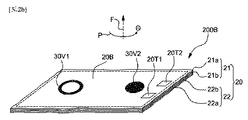
図2A及び図2Bは、本発明の他の実施形態によるバッテリーパッケージ100を示す分解斜視図である。
2A and 2B are exploded perspective views showing a
図2Aを参照すれば、フレキシブル封止体20の中央部に、露出電極20T1、20T2が配置される。このために、バッテリー部10のリード10L1、10L2は、フレキシブル封止体20の内部で、露出電極20T1、20T2との接続のために折り曲げられ、露出電極20T1、20T2まで延びる。他の実施形態において、露出電極20T1、20T2は、二つ以上の複数であり、充放電保護回路または他の回路に連結されてもよい。また、図示していないが、フレキシブル封止体20の内部に、バッテリー部10の充放電保護回路がさらに提供されてもよい。
Referring to FIG. 2A, the exposed electrodes 20T1 and 20T2 are disposed at the center of the
図1Aないし図1Cを参照して上述したように、第1ベルクロ部30V1、30V2、30V2、30V3の形状、個数、大きさ及び/または配置を含むベルクロパターンは、ユーザの不注意なバッテリーパッケージ100の付着試みによって、電極間の極性の整合が行われないままで、バッテリーパッケージ100と外部基材1000とが付着されることを防止するように設計される。図2Aでは、三つのベルクロからなる第1ベルクロ部30V1、30V2、30V3を例示している。三つのベルクロの配置は、外部基材1000上に電極20T1、20T2の極性の整合が行われて付着されることを助ける。例えば、ユーザがバッテリーパッケージ100を付着する方位と異なって、バッテリーパッケージ100の面に垂直な方向(すなわち、矢印Fの方向)にバッテリーパッケージ100を180゜回転させた後に付着する場合、バッテリーパッケージ100の第1ベルクロ部30V1、30V2、30V3と、外部基材1000上の第2ベルクロ部とが互いに対向していないため、付着が行われない。
As described above with reference to FIGS. 1A to 1C, the Velcro pattern including the shape, number, size, and / or arrangement of the first Velcro portions 30V1, 30V2, 30V2, and 30V3 is a
図2Bでは、バッテリーパッケージ100の背面20Bに提供される第1ベルクロ部30V1、30V2が、外部基材1000上の電極1000T1、1000T2と、電極20T1、20T2との極性の整合が行われて付着されることを助けるベルクロの形状に関する他の実施形態が開示されている。第1ベルクロ部30V1、30Vの一つのベルクロは、ドーナツ状30V1を有し、他のベルクロは、板状30V2を有することで、バッテリーパッケージ100の方向を、決められた位置と異なって付着しようとする際には、第1ベルクロ部30V1、30Vと第2ベルクロ部1000V1、1000V2とが互いに対向していないため、付着が行われない。
In FIG. 2B, the first Velcro portions 30V1 and 30V2 provided on the
上述の実施形態においては、バッテリーパッケージ100の背面20Bに垂直な方向(矢印Fの方向)にバッテリーパッケージ100を回転する際、背面20Bに提供されたベルクロの形状、個数、大きさまたは配置に関するベルクロパターンが、Θが360゜範囲内で変わる間、同一なパターンが1回しか表されず、2回以上表されない。これにより、ユーザがバッテリーパッケージ100を外部基材上に方位を間違って合わせて付着しようとする場合に、バッテリーパッケージの第1ベルクロ部と、外部基材上の第2ベルクロ部とが互いに対向していないため、前記ベルクロ部間の結合が行われない。このように、バッテリーパッケージの回転時にベルクロパターンの非対称構成は、本発明の範囲内で、ベルクロの形状、個数、配置またはこれらの組み合わせにより行われる。
In the above-described embodiment, when the
図3は、本発明のさらに他の実施形態によるバッテリーパッケージ200を示す分解斜視図である。
FIG. 3 is an exploded perspective view illustrating a
図3を参照すれば、バッテリーパッケージ200は、フレキシブル封止体20の外側に配置される導電性ベルクロ部31V1、31V2を有する。導電性ベルクロ部31V1、31V2は、フレキシブル封止体20の内部に担持されたバッテリー部10のリード10L1、10L2と電気的に連結される。リード10L1、10L2と導電性ベルクロ部31V1、31V2との電気的連結は、直接行われるか、再配線のための導電性ワイヤー20Wにより行われ、本発明がこれに限定されるものではない。
Referring to FIG. 3, the
この場合、導電性ベルクロ部31V1、31V2は、外部回路との電気的接続のための電極として機能できる。バッテリーパッケージ200の導電性ベルクロ部31V1、31V2と結合する外部基材のベルクロ部、例えば、図4の第2ベルクロ部1000V1、1000V2も、同様に導電性ベルクロからなる。この場合、図1Aに示したバッテリーパッケージ100と異なり、露出電極20T1、20T2、1000T1、1000T2が省略可能である。
In this case, the conductive Velcro portions 31V1 and 31V2 can function as electrodes for electrical connection with an external circuit. Similarly, the Velcro portions of the external base material that are coupled to the conductive Velcro portions 31V1 and 31V2 of the
導電性ベルクロ部31V1、31V2は、導電性高分子纎維、金属纎維、金属化層がコーティングされた高分子纎維、導電性粒子が分散した高分子纎維、炭素纎維またはその混合物を含むことにより、導電性を確保することができる。前記導電性高分子纎維は、非制限的な例として、ポリチオフェン、ポリアニリン、ポリピロール、ポリオキシフェニレン、ポリフェニレンスルファイド、ポリフラン、ポリメチルピロール、ポリスチレン、その誘導体または共重合体を含む。前記金属纎維は、非制限的な例として、ステンレス鋼、白金(Pt)、金(Au)、銀(Ag)、アルミニウム(Al)、銅(Cu)、鉄(Fe)、クロム(Cr)、マンガン(Mn)、ニッケル(Ni)またはその合金を含む。 The conductive Velcro portions 31V1 and 31V2 are made of conductive polymer fiber, metal fiber, polymer fiber coated with a metallized layer, polymer fiber in which conductive particles are dispersed, carbon fiber, or a mixture thereof. By including, electrical conductivity can be ensured. The conductive polymer fiber includes, as a non-limiting example, polythiophene, polyaniline, polypyrrole, polyoxyphenylene, polyphenylene sulfide, polyfuran, polymethylpyrrole, polystyrene, derivatives or copolymers thereof. Non-limiting examples of the metal fibers include stainless steel, platinum (Pt), gold (Au), silver (Ag), aluminum (Al), copper (Cu), iron (Fe), and chromium (Cr). , Manganese (Mn), nickel (Ni) or alloys thereof.
他の実施形態において、導電性ベルクロ部31V1、31V2は、上述のように、バッテリーパッケージ200の背面20Bに垂直な方向(矢印Fの方向)にバッテリーパッケージ100を回転する時、背面20Bに提供されたベルクロ31V1、31V2の形状、個数または配置に関するパターンが、Θが360゜範囲内で変わる間、同一なパターンが1回しか表されず、2回以上表されないように設計される。これにより、ユーザがバッテリーパッケージ200を外部基材上に方位を間違って合わせて付着しようとする場合に、バッテリーパッケージの第1ベルクロ部と、外部基材上の第2ベルクロ部とが互いに対向していないため、前記ベルクロ部間の結合が行われない。
In another embodiment, the conductive Velcro portions 31V1 and 31V2 are provided on the
図4は、本発明の一実施形態によるバッテリーパッケージが付着される外部基材を提供する衣服1000である。
FIG. 4 is a
図4を参照すれば、衣服1000は、スマート衣類の一実施形態であって、外部温度を感知して、低温の場合に防寒のために電力が印加されると、発熱を行うコイル1000Cを駆動する電子回路を有している。コイル1000Cに供給される電力は、バッテリーパッケージ200Aから出力される。図示したバッテリーパッケージ200Aは、図2Aを参照して説明したバッテリーパッケージである。
Referring to FIG. 4, the
バッテリーパッケージ100の第1導電性ベルクロ部30V1、30V2、30V3は、滑らかな面を有し、衣服1000に提供された第2導電性ベルクロ部1000V1、1000V2、1000V3は、粗い面を有し、第1導電性ベルクロ部30V1、30V2、30V3と、第2導電性ベルクロ部1000V1、1000V2、1000V3とが互いに結合されて、外部基材である衣服1000上に付着される。また、バッテリーパッケージ200Aの露出電極20T1、20T2、例えば、正極20T1及び負極20T2は、衣服上の電源端子、例えば、正極1000T1及び負極1000T2に互いに接触し、電気的に連結されて、電力供給のための電源回路を完成することができる。
The first conductive velcro parts 30V1, 30V2, and 30V3 of the
図2Aを参照して上述したように、第1ベルクロ部30V1、30V2、30V3の形状、大きさ及び/または配置は、ユーザの不注意なバッテリーパッケージ200Aの付着試みによって、電極間の極性の整合が行われないままで、バッテリーパッケージ200Aと外部基材1000とが付着されることを防止するように設計される。三つのベルクロ30V1、30V2、30V3の配置は、外部基材1000上に、バッテリーパッケージの正極20T1及び負極20T2が、外部基材1000上の電源端子である正極1000T1及び負極1000T2に整合されて付着されるようにする。
As described above with reference to FIG. 2A, the shape, size, and / or arrangement of the first Velcro portions 30V1, 30V2, and 30V3 may be adjusted according to the polarity of the electrodes due to the user's careless attachment of the
ユーザがバッテリーパッケージ200Aを付着する方位と異なって、バッテリーパッケージ200Aの下端部200Eを衣服1000の上方へ、すなわち、バッテリーパッケージ200Aの下端部200Eがユーザの頭方へ向かったままで、バッテリーパッケージ200Aを、衣服1000のバッテリーパッケージの位置1000Sに付着しようとすると、バッテリーパッケージ200Aの第1ベルクロ部30V1、30V2、30V3と、外部基材1000上の第2ベルクロ部1000V1、1000V2、1000V3とが互いに対向していないため、付着が行われない。したがって、本発明の実施形態によれば、ユーザの不注意な付着試みによる極性エラーを防止することができる。
Unlike the orientation in which the user attaches the
バッテリーパッケージ200Aのフレキシブル封止体20は、織物親和的表面層22aを有し、その前面に字または絵のような情報40を表示することにより、バッテリーとしてはいうまでもなく、衣服そのものの審美性を高める装飾的効果を提供する。また、ユーザは、消耗したバッテリーパッケージ200Aを容易にむしり取って、衣服1000から分離した後、好適な充電器によりこれを充電した後に再び衣服1000に付着することにより、コイル1000Cを再び動作させることができる。前記充電器も、バッテリーパッケージの導電性ベルクロ部と結合されて対をなす導電性ベルクロ部を有し、これらの導電性ベルクロ部が結合されることにより、バッテリーパッケージ200Aのバッテリー部が充電できるであろう。
The
衣服1000は、電気を消耗するものであり、バッテリーパッケージ200Aが電力を供給する放電過程について述べられているが、本発明の電子回路は、電力消耗装置に制限されるものではない。例えば、バッテリーパッケージ200A内の電池セルが二次電池セルである場合、衣服1000内に設けられた電子回路は、圧電素子のようなエネルギーハーベスト装置であってもよい。また、これにより生産された電力をバッテリーパッケージ200Aにより蓄電することができ、蓄電された電気を再び活用できるであろう。また、他の実施形態において、前記電子回路は、電力消耗装置とエネルギーハーベスト装置との組み合わせであり、エネルギーを収集し、これを再使用するのにバッテリーパッケージが使われることも可能である。
The
上述の実施形態において、外部基材として、衣服は例示的であり、電気を必要とする帽子、かばん、テント、履き物、または電気を生産する帽子、かばん、履き物のような他の纎維材質の基材も、本発明の実施形態に含まれる。 In the embodiments described above, the garment is exemplary as the external substrate, and is made of hats, bags, tents, footwear that require electricity, or other textile materials such as hats, bags, footwear that produce electricity. Substrates are also included in embodiments of the present invention.
以上で説明した本発明は、前述した実施形態及び添付された図面に限定されず、本発明の技術的思想を逸脱しない範囲内で、色々な置換、変形及び変更が可能であるということは、本発明が属する技術分野で通常の知識を持った者にとって明らかである。 The present invention described above is not limited to the above-described embodiment and attached drawings, and various substitutions, modifications, and changes are possible without departing from the technical idea of the present invention. It will be apparent to those skilled in the art to which the present invention pertains.
本発明の実施形態によれば、バッテリー部を内部に担持するフレキシブル封止体と、これを外部基材上に付着するためのベルクロとを利用して、織物製品である外部基材上に着脱可能に適用されるので、電力の供給またはエネルギーの収集が容易に可能なバッテリーパッケージが提供できる。 According to an embodiment of the present invention, a flexible sealing body that carries a battery portion therein and a velcro for attaching the battery portion onto an external base material are attached to and detached from the external base material that is a textile product. Since it can be applied, a battery package that can easily supply power or collect energy can be provided.
Claims (26)
一つ以上の二次電池セルと、前記二次電池セルと連結されて、露出したリードとを有するバッテリー部と、
前記バッテリー部を内部に担持するフレキシブル封止体と、
前記フレキシブル封止体の表面上に露出し、前記リードと電気的に連結されて、前記電子回路と電気的に接続する露出電極と、
前記フレキシブル封止体の前記表面上に配置される第1ベルクロ部と、を含み、
前記バッテリーパッケージの前記第1ベルクロ部は、前記外部基材上に配置される第2ベルクロ部に結束されて、前記バッテリーパッケージが前記外部基材上に着脱可能に固定され、前記バッテリーパッケージの前記露出電極と、前記外部基材の電源端子とが接続して、前記電子回路のための電源回路を形成するバッテリーパッケージ。 A battery that is attached on an external substrate including an electronic circuit and a power supply terminal electrically connected to the electronic circuit, and stores energy by supplying power to the electronic circuit or collecting power. A package,
A battery unit having at least one secondary battery cell and an exposed lead connected to the secondary battery cell;
A flexible sealing body carrying the battery part therein;
An exposed electrode that is exposed on a surface of the flexible sealing body, electrically connected to the lead, and electrically connected to the electronic circuit;
A first Velcro portion disposed on the surface of the flexible sealing body,
The first Velcro portion of the battery package is bound to a second Velcro portion disposed on the external base material, and the battery package is detachably fixed on the external base material. A battery package in which an exposed electrode and a power supply terminal of the external base material are connected to form a power supply circuit for the electronic circuit.
一つ以上の二次電池セルと、前記二次電池セルと連結されて、露出したリードとを有するバッテリー部と、
前記バッテリー部を内部に担持するフレキシブル封止体と、
前記フレキシブル封止体の表面上に露出し、前記リードと電気的に連結されて、前記電子回路と電気的に接続する第1導電性ベルクロ部と、を含み、
前記バッテリーパッケージの前記第1導電性ベルクロ部は、前記外部基材上に配置される第2導電性ベルクロ部に結束されて、前記バッテリーパッケージが前記外部基材上に着脱可能に固定され、前記バッテリーパッケージの前記第1導電性ベルクロ部と、前記外部基材の前記第2導電性ベルクロ部とが接続して、前記電子回路のための電源回路を形成するバッテリーパッケージ。 A battery that is attached on an external substrate including an electronic circuit and a power supply terminal electrically connected to the electronic circuit, and stores energy by supplying power to the electronic circuit or collecting power. A package,
A battery unit having at least one secondary battery cell and an exposed lead connected to the secondary battery cell;
A flexible sealing body carrying the battery part therein;
A first conductive Velcro portion exposed on the surface of the flexible sealing body, electrically connected to the lead, and electrically connected to the electronic circuit;
The first conductive Velcro portion of the battery package is bound to a second conductive Velcro portion disposed on the external base material, and the battery package is detachably fixed on the external base material, A battery package in which the first conductive Velcro portion of the battery package and the second conductive Velcro portion of the external base material are connected to form a power supply circuit for the electronic circuit.
Applications Claiming Priority (3)
| Application Number | Priority Date | Filing Date | Title |
|---|---|---|---|
| KR10-2014-0115707 | 2014-09-01 | ||
| KR1020140115707A KR101681906B1 (en) | 2014-09-01 | 2014-09-01 | Fabric-friendly rechargeable battery package |
| PCT/KR2015/007601 WO2016036003A1 (en) | 2014-09-01 | 2015-07-22 | Fabric-friendly type secondary battery package |
Publications (2)
| Publication Number | Publication Date |
|---|---|
| JP2017529665A true JP2017529665A (en) | 2017-10-05 |
| JP6454410B2 JP6454410B2 (en) | 2019-01-16 |
Family
ID=55440024
Family Applications (1)
| Application Number | Title | Priority Date | Filing Date |
|---|---|---|---|
| JP2017511930A Expired - Fee Related JP6454410B2 (en) | 2014-09-01 | 2015-07-22 | Fabric-friendly secondary battery package |
Country Status (7)
| Country | Link |
|---|---|
| US (1) | US10381607B2 (en) |
| EP (1) | EP3190640B1 (en) |
| JP (1) | JP6454410B2 (en) |
| KR (1) | KR101681906B1 (en) |
| CN (1) | CN106663756B (en) |
| ES (1) | ES2752219T3 (en) |
| WO (1) | WO2016036003A1 (en) |
Families Citing this family (5)
| Publication number | Priority date | Publication date | Assignee | Title |
|---|---|---|---|---|
| US9947905B2 (en) * | 2015-06-19 | 2018-04-17 | Intel Corporation | Fabric battery |
| US11936070B2 (en) | 2020-07-10 | 2024-03-19 | Bloomer Health Tech Inc. | System and method for a wearable circuit |
| US11560701B2 (en) | 2020-09-04 | 2023-01-24 | Delta Faucet Company | Conductive bonnet nut for an electronic faucet |
| USD952863S1 (en) | 2020-10-08 | 2022-05-24 | Bloomer Health Tech Inc. | Monitoring garment |
| CN114530633B (en) * | 2022-01-14 | 2023-06-23 | 北京纳米能源与系统研究所 | Wearable and chargeable and dischargeable fabric, preparation method thereof and method for charging and discharging fabric |
Citations (8)
| Publication number | Priority date | Publication date | Assignee | Title |
|---|---|---|---|---|
| JPS59189555A (en) * | 1983-04-09 | 1984-10-27 | Tomoyuki Aoki | Flexible thin battery |
| JPH03205757A (en) * | 1990-01-05 | 1991-09-09 | Shin Kobe Electric Mach Co Ltd | Package of power supply for electronic apparatus |
| JPH09260803A (en) * | 1996-03-26 | 1997-10-03 | Toshiba Battery Co Ltd | Wiring board with cell |
| US20030212319A1 (en) * | 2000-10-10 | 2003-11-13 | Magill Alan Remy | Health monitoring garment |
| KR20110090246A (en) * | 2010-02-03 | 2011-08-10 | 한국과학기술원 | Power supply apparatus of wearble systems |
| WO2012105160A1 (en) * | 2011-01-31 | 2012-08-09 | 三洋電機株式会社 | Battery module |
| JP2013048510A (en) * | 2011-08-29 | 2013-03-07 | Panasonic Corp | Battery device and operation method thereof |
| US20130171490A1 (en) * | 2011-12-29 | 2013-07-04 | Apple Inc. | Flexible battery pack |
Family Cites Families (11)
| Publication number | Priority date | Publication date | Assignee | Title |
|---|---|---|---|---|
| JPS5063895A (en) | 1973-10-09 | 1975-05-30 | ||
| JPS59154731A (en) * | 1983-02-21 | 1984-09-03 | Hitachi Ltd | Charged beam deflection system |
| US4696066A (en) * | 1986-09-15 | 1987-09-29 | Ball Joyce A | Heated coat liner |
| US5569549A (en) * | 1995-03-17 | 1996-10-29 | Tv Interactive Data Corporation | Method and structure for attaching a battery to an electrical device |
| US5531601A (en) * | 1995-06-23 | 1996-07-02 | Amoroso; Eugene C. | Fabric battery pouch |
| AU2003293334A1 (en) * | 2002-12-02 | 2004-06-23 | Santa Fe Science And Technology, Inc. | Resistive heating using polyaniline fiber |
| JP5063895B2 (en) * | 2003-11-05 | 2012-10-31 | 株式会社Gsユアサ | battery |
| KR20070060976A (en) * | 2005-12-08 | 2007-06-13 | 한국전자통신연구원 | User friendly wearable computing system and method |
| US8628506B2 (en) * | 2008-06-30 | 2014-01-14 | Kimberly-Clark Worldwide, Inc. | Multifunctional monitoring device for absorbent articles |
| KR20110067398A (en) * | 2009-12-14 | 2011-06-22 | 한국전자통신연구원 | Garment having function for supplying power using solar cell |
| KR101491873B1 (en) * | 2010-09-02 | 2015-02-10 | 한국전자통신연구원 | Pouch-Type Flexible Rechargeable Film Battery And Method of Manufacturing the Same |
-
2014
- 2014-09-01 KR KR1020140115707A patent/KR101681906B1/en active IP Right Grant
-
2015
- 2015-07-22 EP EP15837281.3A patent/EP3190640B1/en active Active
- 2015-07-22 WO PCT/KR2015/007601 patent/WO2016036003A1/en active Application Filing
- 2015-07-22 CN CN201580046928.6A patent/CN106663756B/en not_active Expired - Fee Related
- 2015-07-22 JP JP2017511930A patent/JP6454410B2/en not_active Expired - Fee Related
- 2015-07-22 US US15/507,458 patent/US10381607B2/en not_active Expired - Fee Related
- 2015-07-22 ES ES15837281T patent/ES2752219T3/en active Active
Patent Citations (9)
| Publication number | Priority date | Publication date | Assignee | Title |
|---|---|---|---|---|
| JPS59189555A (en) * | 1983-04-09 | 1984-10-27 | Tomoyuki Aoki | Flexible thin battery |
| JPH03205757A (en) * | 1990-01-05 | 1991-09-09 | Shin Kobe Electric Mach Co Ltd | Package of power supply for electronic apparatus |
| JPH09260803A (en) * | 1996-03-26 | 1997-10-03 | Toshiba Battery Co Ltd | Wiring board with cell |
| US20030212319A1 (en) * | 2000-10-10 | 2003-11-13 | Magill Alan Remy | Health monitoring garment |
| KR20110090246A (en) * | 2010-02-03 | 2011-08-10 | 한국과학기술원 | Power supply apparatus of wearble systems |
| WO2012105160A1 (en) * | 2011-01-31 | 2012-08-09 | 三洋電機株式会社 | Battery module |
| JP2013048510A (en) * | 2011-08-29 | 2013-03-07 | Panasonic Corp | Battery device and operation method thereof |
| US20130171490A1 (en) * | 2011-12-29 | 2013-07-04 | Apple Inc. | Flexible battery pack |
| JP2015507814A (en) * | 2011-12-29 | 2015-03-12 | アップル インコーポレイテッド | Flexible battery pack |
Also Published As
| Publication number | Publication date |
|---|---|
| EP3190640A1 (en) | 2017-07-12 |
| ES2752219T3 (en) | 2020-04-03 |
| EP3190640B1 (en) | 2019-08-28 |
| KR101681906B1 (en) | 2016-12-02 |
| JP6454410B2 (en) | 2019-01-16 |
| CN106663756A (en) | 2017-05-10 |
| KR20160026577A (en) | 2016-03-09 |
| CN106663756B (en) | 2019-11-22 |
| EP3190640A4 (en) | 2018-05-09 |
| US20170288180A1 (en) | 2017-10-05 |
| US10381607B2 (en) | 2019-08-13 |
| WO2016036003A1 (en) | 2016-03-10 |
Similar Documents
| Publication | Publication Date | Title |
|---|---|---|
| JP6454410B2 (en) | Fabric-friendly secondary battery package | |
| US5531601A (en) | Fabric battery pouch | |
| CN104273891B (en) | Brilliant Eyes mirror case | |
| JP4683373B2 (en) | Power system | |
| WO2006114737A1 (en) | Apparatus, system and method for battery connections | |
| CN106030887A (en) | Thin battery and battery-mounted device | |
| US10863780B2 (en) | Component for garment or textile product | |
| JP6362065B2 (en) | Battery built-in belt | |
| CN111244526A (en) | Flexible battery and electronic equipment | |
| JP6211174B2 (en) | Composite film and method for producing the same | |
| JP2002218769A (en) | Clothing provided with piezoelectric power generator or power generator for clothing | |
| KR101652293B1 (en) | Fabric Type Independent Power Plant Having Advanced Structure for Harvesting Frictional Electricity, and Fabric Product Having the Same | |
| CN107645915A (en) | functional clothes | |
| CN208479491U (en) | Friction generator based on public electrode | |
| CN209170301U (en) | A kind of flexible solar positioning component and its clothes | |
| JP3177222U (en) | Heated piece structure sewn on clothing | |
| US10535845B1 (en) | Flexible and stretchable chain battery | |
| KR20170072703A (en) | Auxiliary battery | |
| JP3197738U (en) | Fever liner | |
| CN208850715U (en) | A kind of fabric structure with anti-stab pooling feature | |
| CN208797013U (en) | A kind of thin film solar component and positioning device | |
| CN216908927U (en) | Wearable massage equipment | |
| CN209361675U (en) | A kind of heating waistband | |
| CN111743229A (en) | Solar power generation clothes | |
| CN109951099A (en) | Friction generator based on public electrode |
Legal Events
| Date | Code | Title | Description |
|---|---|---|---|
| A977 | Report on retrieval |
Free format text: JAPANESE INTERMEDIATE CODE: A971007 Effective date: 20180125 |
|
| A131 | Notification of reasons for refusal |
Free format text: JAPANESE INTERMEDIATE CODE: A131 Effective date: 20180206 |
|
| A601 | Written request for extension of time |
Free format text: JAPANESE INTERMEDIATE CODE: A601 Effective date: 20180507 |
|
| A521 | Request for written amendment filed |
Free format text: JAPANESE INTERMEDIATE CODE: A523 Effective date: 20180521 |
|
| A131 | Notification of reasons for refusal |
Free format text: JAPANESE INTERMEDIATE CODE: A131 Effective date: 20180807 |
|
| A521 | Request for written amendment filed |
Free format text: JAPANESE INTERMEDIATE CODE: A523 Effective date: 20181105 |
|
| TRDD | Decision of grant or rejection written | ||
| A01 | Written decision to grant a patent or to grant a registration (utility model) |
Free format text: JAPANESE INTERMEDIATE CODE: A01 Effective date: 20181204 |
|
| A61 | First payment of annual fees (during grant procedure) |
Free format text: JAPANESE INTERMEDIATE CODE: A61 Effective date: 20181214 |
|
| R150 | Certificate of patent or registration of utility model |
Ref document number: 6454410 Country of ref document: JP Free format text: JAPANESE INTERMEDIATE CODE: R150 |
|
| LAPS | Cancellation because of no payment of annual fees |