JP2017529183A - Spine connector and related methods - Google Patents
Spine connector and related methods Download PDFInfo
- Publication number
- JP2017529183A JP2017529183A JP2017516476A JP2017516476A JP2017529183A JP 2017529183 A JP2017529183 A JP 2017529183A JP 2017516476 A JP2017516476 A JP 2017516476A JP 2017516476 A JP2017516476 A JP 2017516476A JP 2017529183 A JP2017529183 A JP 2017529183A
- Authority
- JP
- Japan
- Prior art keywords
- connector
- spinal fixation
- clamp
- fixation element
- spinal
- Prior art date
- Legal status (The legal status is an assumption and is not a legal conclusion. Google has not performed a legal analysis and makes no representation as to the accuracy of the status listed.)
- Granted
Links
Images


Classifications
-
- A—HUMAN NECESSITIES
- A61—MEDICAL OR VETERINARY SCIENCE; HYGIENE
- A61B—DIAGNOSIS; SURGERY; IDENTIFICATION
- A61B17/00—Surgical instruments, devices or methods, e.g. tourniquets
- A61B17/56—Surgical instruments or methods for treatment of bones or joints; Devices specially adapted therefor
- A61B17/58—Surgical instruments or methods for treatment of bones or joints; Devices specially adapted therefor for osteosynthesis, e.g. bone plates, screws, setting implements or the like
- A61B17/68—Internal fixation devices, including fasteners and spinal fixators, even if a part thereof projects from the skin
- A61B17/70—Spinal positioners or stabilisers ; Bone stabilisers comprising fluid filler in an implant
- A61B17/7049—Connectors, not bearing on the vertebrae, for linking longitudinal elements together
-
- A—HUMAN NECESSITIES
- A61—MEDICAL OR VETERINARY SCIENCE; HYGIENE
- A61B—DIAGNOSIS; SURGERY; IDENTIFICATION
- A61B17/00—Surgical instruments, devices or methods, e.g. tourniquets
- A61B17/56—Surgical instruments or methods for treatment of bones or joints; Devices specially adapted therefor
- A61B17/58—Surgical instruments or methods for treatment of bones or joints; Devices specially adapted therefor for osteosynthesis, e.g. bone plates, screws, setting implements or the like
- A61B17/68—Internal fixation devices, including fasteners and spinal fixators, even if a part thereof projects from the skin
- A61B17/70—Spinal positioners or stabilisers ; Bone stabilisers comprising fluid filler in an implant
- A61B17/7001—Screws or hooks combined with longitudinal elements which do not contact vertebrae
- A61B17/7002—Longitudinal elements, e.g. rods
- A61B17/7011—Longitudinal element being non-straight, e.g. curved, angled or branched
-
- A—HUMAN NECESSITIES
- A61—MEDICAL OR VETERINARY SCIENCE; HYGIENE
- A61B—DIAGNOSIS; SURGERY; IDENTIFICATION
- A61B17/00—Surgical instruments, devices or methods, e.g. tourniquets
- A61B17/56—Surgical instruments or methods for treatment of bones or joints; Devices specially adapted therefor
- A61B17/58—Surgical instruments or methods for treatment of bones or joints; Devices specially adapted therefor for osteosynthesis, e.g. bone plates, screws, setting implements or the like
- A61B17/68—Internal fixation devices, including fasteners and spinal fixators, even if a part thereof projects from the skin
- A61B17/70—Spinal positioners or stabilisers ; Bone stabilisers comprising fluid filler in an implant
- A61B17/7049—Connectors, not bearing on the vertebrae, for linking longitudinal elements together
- A61B17/705—Connectors, not bearing on the vertebrae, for linking longitudinal elements together for linking adjacent ends of longitudinal elements
Abstract
いくつかの実施形態において、コネクターは、第1の固定エレメント(例えば、第1のロッド)を第2の固定エレメント(例えば、第2のロッド)に連結するよう構成することができる。第1及び第2の固定エレメントの一方若しくは両方が、このコネクターに含まれてよく、又は一方若しくは両方が、別々に提供されてもよい。いくつかの例において、固定エレメントのうち少なくとも1つが、患者に以前に埋め込まれたものである。このコネクターは、第1及び第2の固定エレメントの間に、1つ又は2つ以上の自由度を提供し得る。このコネクターは更に、(1)1つ又は2つ以上の固定エレメントをコネクターにロックし、かつ(2)固定エレメント間の1つ又は2つ以上の自由度をロックするよう構成された、ロックエレメントを含み得る。このコネクターは、触覚的フィードバック及び/又は聴覚的フィードバックを外科医に提供するような様相で、固定エレメントにスナップ嵌め又は他の方法で係合するよう構成され得る。In some embodiments, the connector can be configured to couple a first securing element (eg, a first rod) to a second securing element (eg, a second rod). One or both of the first and second securing elements may be included in the connector, or one or both may be provided separately. In some examples, at least one of the fixation elements has been previously implanted in the patient. The connector may provide one or more degrees of freedom between the first and second securing elements. The connector further includes a locking element configured to (1) lock one or more securing elements to the connector and (2) lock one or more degrees of freedom between the securing elements. Can be included. The connector may be configured to snap or otherwise engage the fixation element in such a manner as to provide tactile and / or audible feedback to the surgeon.
Description
脊椎インプラントコネクター及び関連方法が本明細書に開示される。 A spinal implant connector and related methods are disclosed herein.
固定システムは、2つ以上の骨又は骨片の間の望ましい位置関係を整列及び/又は固定するための整形外科手術に使用することができる。例えば、脊椎手術において、脊椎固定システムを使用して、椎体間の望ましい位置関係を整列及び/又は固定することができる。そのようなデバイスは典型的に、例えば、比較的剛性の固定ロッドなどの脊椎固定エレメントを含み、様々なアンカーデバイス(例えば、フック、ボルト、ワイヤー、又はねじ)にこのエレメントを取り付けることにより、椎骨に連結される。この固定エレメントは、望ましい補正又は固定に基づいて選択された、所定の又は調整可能な外形を有し得る。いったん据え付けられると、この固定エレメントは、望ましい治癒若しくは脊椎固定が生じるまでか、又は別の期間のいずれかの間、望ましい空間的関係で椎骨を保持する。 The fixation system can be used in orthopedic surgery to align and / or fix a desired positional relationship between two or more bones or bone fragments. For example, in spinal surgery, a spinal fixation system can be used to align and / or fix a desired positional relationship between vertebral bodies. Such devices typically include spinal fixation elements such as, for example, relatively rigid fixation rods, and by attaching this element to various anchor devices (eg, hooks, bolts, wires, or screws), the vertebrae Connected to The fixation element may have a predetermined or adjustable profile selected based on the desired correction or fixation. Once installed, the fixation element holds the vertebrae in the desired spatial relationship either until the desired healing or spinal fixation occurs or for another period of time.
複数の脊椎固定エレメントを互いに連結するのに望ましい可能性がある例はたくさん存在する。例えば、患者の解剖学的構造、外科医が使用する技法、及び/又は望ましい補正の様々な状況により、複数の脊椎ロッドを互いに連結させる必要が生じ得る。更なる例として、一部の再置換手術において、新たに設置された脊椎ロッドを以前に設置されたロッドに連結することによって、以前に設置された構築物を、追加の脊椎レベルまで延在させることが望ましい場合がある。更に別の一例として、複数のロッドを互いに連結することにより、埋め込まれている構築物の全体的な強度及び安定性を改善することができる。 There are many examples that may be desirable for connecting multiple spinal fixation elements together. For example, the patient's anatomy, the technique used by the surgeon, and / or various circumstances of the desired correction may require that multiple spinal rods be coupled together. As a further example, in some revision surgery, extending a previously installed construct to an additional vertebral level by connecting a newly installed spinal rod to a previously installed rod. May be desirable. As yet another example, multiple rods can be connected together to improve the overall strength and stability of the embedded construct.
1つ又は2つ以上の経皮的作業チャンネルを介して脊椎固定システムの設置を容易にすることにより、患者の外傷を縮小しかつ回復時間を短縮するための、低侵襲性手術技法が開発されている。しかしながらこれらの技法は、互いに連結するための複数の固定エレメントを設置する場合、あるいは、再置換手術中に、新しい固定エレメントを以前に設置された構築物に連結する場合には、十分に適していないことが多い。開放手術においても、複数の固定エレメントを互いに連結するための既存システムは、扱いにくく、使用が難しい場合がある。したがって、改善された脊椎コネクター及び関連方法のニーズが存在する。 Minimally invasive surgical techniques have been developed to reduce patient trauma and reduce recovery time by facilitating the placement of spinal fixation systems through one or more percutaneous working channels. ing. However, these techniques are not well suited when installing multiple fixation elements to connect to each other, or when connecting a new fixation element to a previously installed construct during revision surgery. There are many cases. Even in open surgery, existing systems for connecting a plurality of fixation elements to each other can be cumbersome and difficult to use. Accordingly, there is a need for improved spinal connectors and related methods.
いくつかの実施形態において、コネクターは、第1の固定エレメント(例えば、第1のロッド)を第2の固定エレメント(例えば、第2のロッド)に連結するよう構成することができる。第1及び第2の固定エレメントの一方若しくは両方が、このコネクターに含まれてよく、又は一方若しくは両方が、別々に提供されてもよい。いくつかの例において、固定エレメントのうち少なくとも1つが、患者に以前に埋め込まれたものである。このコネクターは、第1及び第2の固定エレメントの間に、1つ又は2つ以上の自由度を提供し得る。このコネクターは更に、(1)1つ又は2つ以上の固定エレメントをコネクターにロックし、かつ(2)固定エレメント間の1つ又は2つ以上の自由度をロックするよう構成された、ロックエレメントを含み得る。このコネクターは、触覚的フィードバック及び/又は聴覚的フィードバックを外科医に提供するような様相で、固定エレメントにスナップ嵌め又は他の方法で係合するよう構成され得る。この固定部材のうち少なくとも1つは、患者の解剖学的構造に対し、又はコネクターを取り付ける固定構築物のコンポーネントのための、クリアランスを提供するために、屈曲又は突出を含み得る。このコネクターは、様々な手術方法に使用することができ、これには、既存の固定構築物を1つ又は2つ以上の追加の椎骨レベルまで延在させる、低侵襲性再置換術が含まれる。 In some embodiments, the connector can be configured to couple a first securing element (eg, a first rod) to a second securing element (eg, a second rod). One or both of the first and second securing elements may be included in the connector, or one or both may be provided separately. In some examples, at least one of the fixation elements has been previously implanted in the patient. The connector may provide one or more degrees of freedom between the first and second securing elements. The connector further includes a locking element configured to (1) lock one or more securing elements to the connector and (2) lock one or more degrees of freedom between the securing elements. Can be included. The connector may be configured to snap or otherwise engage the fixation element in such a manner as to provide tactile and / or audible feedback to the surgeon. At least one of the fixation members may include a bend or a protrusion to provide clearance for the patient's anatomy or for a component of the fixation construct that attaches the connector. The connector can be used in a variety of surgical methods, including minimally invasive revision surgery that extends existing fixation constructs to one or more additional vertebral levels.
いくつかの実施形態において、脊椎コネクターは、第1の脊椎固定エレメントを含み、これは、開口部と、嵌合機構に連結された接続アセンブリとを画定し、これにより接続アセンブリの少なくとも一部分が、嵌合機構の開口部内に受容される。この接続アセンブリは、第2の脊椎固定エレメント及びロックエレメントを受容するよう構成された陥凹部を画定するクランプを含み得、このロックエレメントは、クランプを第2の脊椎固定エレメントに選択的にロックし、かつ、接続アセンブリの1つ又は2つ以上の自由度をロックするよう構成されている。 In some embodiments, the spinal connector includes a first spinal fixation element that defines an opening and a connection assembly coupled to the mating mechanism, whereby at least a portion of the connection assembly includes: It is received in the opening of the fitting mechanism. The connection assembly may include a clamp that defines a recess configured to receive the second spinal fixation element and the locking element, the locking element selectively locking the clamp to the second spinal fixation element. And is configured to lock one or more degrees of freedom of the connection assembly.
この1つ又は2つ以上の自由度は、第1の脊椎固定エレメントが開口部の長手方向軸を中心にクランプに対して回転可能な第1の回転自由度と、第1の脊椎固定エレメントが開口部の横断方向軸を中心にクランプに対して回転可能な第2の回転自由度と、を含み得る。このクランプは、第1の脊椎固定エレメントの嵌合機構の開口部を通って延在するよう構成された細長いスタッド部分を含み得、これによりこのスタッド部分は開口部の長手方向軸を中心に回転することができ、またこのスタッド部分は開口部の横断方向軸を中心に回転することができる。このロックエレメントは、クランプのスタッド部分にねじで係合するよう構成されたロックナットを含み得る。この接続アセンブリは、ロックナットと第1の脊椎固定エレメントの嵌合機構との間で、クランプのスタッド部分の周囲に配置されたワッシャーを含み得る。このワッシャーは、歯が形成された第1及び第2の陥凹部を含み得、この歯は、嵌合機構上に形成された第1及び第2の突出部が少なくとも部分的に陥凹部に受容されているときに、突出部の上に形成された対応する歯と噛み合うよう構成されている。このクランプは、丁番部分で互いに連結される第1及び第2のアームを含み得、このクランプの外側表面は先細になっていてよく、これにより、ロックエレメントをクランプの長手方向軸に沿って前進させると、クランプのアームを合わせて圧搾するのに有効である。この丁番部分は、一体丁番を含み得る。この脊椎コネクターは、嵌合機構から外向きに延在し、かつ第1の脊椎固定エレメントを挿入デバイスに連結するよう構成されている、連結部材を含み得る。このクランプは、第2の脊椎固定エレメントが陥凹部内に受容されたときに、聴覚的フィードバック及び触覚的フィードバックのうち少なくとも1つを提供するよう構成され得る。第1の脊椎固定エレメントは、第1の細長部分と、第1の細長部分に平行でありかつ1つ又は2つ以上の次元において第1の細長部分からずれている第2の細長部分と、第1の細長部分と第2の細長部分とを接続する中間部分と、を含み得る。この中間部分は、クランプが第2の脊椎固定エレメントに取り付けられているときに、第2の脊椎固定エレメントに連結された骨アンカーの回りで屈曲するような形状であり得る。この嵌合機構は、第1の脊椎固定エレメントと一体形成された環形本体を含み得る。この開口部は、それ自体の内側表面内に形成された浮き彫りを含み得、これにより開口部内でのクランプの角度付けを容易にすることができる。この嵌合機構は、第1の脊椎固定エレメントの端部分から長手方向に延在し得る。この嵌合機構は、第1の脊椎固定エレメントの端部から横断方向に延在し得る。この接続アセンブリは、第1及び第2のシューが摺動可能に配置されたハウジングを含み得、このロックエレメントは、この第1のシューを押して嵌合機構に係合させることによりハウジングに対する第1の脊椎固定エレメントの向きをロックし、かつ、この第2のシューを押して第2の脊椎固定エレメントに係合させることによりクランプ内に第2の脊椎固定エレメントをロックするよう構成されている。このクランプは、間に付勢エレメントを備えた上側クランプアーム及び下側クランプアームを含み得、このロックエレメントは、上側クランプアーム、付勢エレメント、及び下側クランプアームの中に形成された開口部を通って延在する。1つ又は2つ以上の自由度には、第1の脊椎固定エレメントがロックエレメントの長手方向軸を中心として上側及び下側クランプアームに対して回転可能な、回転自由度を含み得る。 The one or more degrees of freedom include a first rotational degree of freedom in which the first spinal fixation element is rotatable relative to the clamp about the longitudinal axis of the opening, and the first spinal fixation element is A second degree of freedom of rotation that is rotatable relative to the clamp about the transverse axis of the opening. The clamp may include an elongated stud portion configured to extend through the opening of the mating mechanism of the first spinal fixation element so that the stud portion rotates about the longitudinal axis of the opening. And the stud portion can rotate about the transverse axis of the opening. The locking element may include a lock nut configured to threadably engage a stud portion of the clamp. The connection assembly may include a washer disposed about the stud portion of the clamp between the lock nut and the mating mechanism of the first spinal fixation element. The washer may include first and second recesses in which teeth are formed, the teeth being at least partially received in the recesses by the first and second protrusions formed on the mating mechanism. When configured, it is configured to mesh with corresponding teeth formed on the protrusion. The clamp may include first and second arms that are connected to each other at a hinge portion, and the outer surface of the clamp may be tapered, thereby allowing the locking element to move along the longitudinal axis of the clamp. When advanced, it is effective to squeeze together the arms of the clamp. The hinge portion may include a living hinge. The spinal connector can include a coupling member that extends outward from the mating mechanism and is configured to couple the first spinal fixation element to the insertion device. The clamp may be configured to provide at least one of audio feedback and tactile feedback when the second spinal fixation element is received in the recess. The first spinal fixation element includes a first elongate portion and a second elongate portion that is parallel to the first elongate portion and that is offset from the first elongate portion in one or more dimensions; An intermediate portion connecting the first elongate portion and the second elongate portion. This intermediate portion may be shaped to bend around a bone anchor coupled to the second spinal fixation element when the clamp is attached to the second spinal fixation element. The mating mechanism may include an annulus body that is integrally formed with the first spinal fixation element. The opening can include a relief formed in its own inner surface, which can facilitate angling of the clamp within the opening. This mating mechanism may extend longitudinally from the end portion of the first spinal fixation element. This mating mechanism may extend transversely from the end of the first spinal fixation element. The connection assembly may include a housing in which the first and second shoes are slidably disposed, and the locking element includes a first to the housing by pushing the first shoe into engagement with the mating mechanism. The spinal fixation element is configured to lock the orientation of the spinal fixation element and to lock the second spinal fixation element within the clamp by pushing the second shoe into engagement with the second spinal fixation element. The clamp may include an upper clamp arm and a lower clamp arm with a biasing element therebetween, the locking element having an opening formed in the upper clamp arm, the biasing element, and the lower clamp arm. Extending through. One or more degrees of freedom may include rotational degrees of freedom in which the first spinal fixation element is rotatable relative to the upper and lower clamp arms about the longitudinal axis of the locking element.
いくつかの実施形態において、脊椎コネクターは、脊椎固定エレメントを把持するよう構成された第1及び第2のアームを有するクランプであって、この第1及び第2のアームの少なくとも一部分がスタッド部分を画定する、クランプと;このクランプのスタッド部分が通って延在する開口部を画定する嵌合機構を有する、脊椎固定エレメントと;このスタッド部分と係合することにより、第1及び第2のアームを互いに向かって選択的に動かし、かつ、このスタッド部分の、開口部の長手方向軸を中心とした回転、及び開口部の横断方向軸を中心とした回転をロックするように構成された、ロックエレメントと;を含む。 In some embodiments, the spinal connector is a clamp having first and second arms configured to grip a spinal fixation element, at least a portion of the first and second arms having a stud portion. Defining a clamp; a spinal fixation element having a mating mechanism defining an opening through which the stud portion of the clamp extends; and first and second arms by engaging the stud portion Locks configured to selectively move the studs toward each other and lock the rotation of the stud portion about the longitudinal axis of the opening and the rotation about the transverse axis of the opening. And an element.
このロックエレメントは、クランプのスタッド部分にねじで係合するよう構成されたロックナットを含み得る。この脊椎コネクターは、ロックナットと脊椎固定エレメントの嵌合機構との間で、クランプのスタッド部分の周囲に配置されたワッシャーを含み得る。このワッシャーは、表面特徴が形成された第1及び第2の陥凹部を含み得、この表面特徴は、嵌合機構上に形成された第1及び第2の突出部が少なくとも部分的に陥凹部に受容されているときに、第1及び第2の突出部の上に形成された対応する表面特徴と噛み合うよう構成されている。この第1及び第2のアームは丁番部分で互いに連結され得、かつこのクランプの外側表面は先細になっていてよく、これにより、ロックエレメントをクランプの長手方向軸に沿って前進させると、クランプのアームを合わせて圧搾するのに有効である。 The locking element may include a lock nut configured to threadably engage a stud portion of the clamp. The spinal connector may include a washer disposed around the stud portion of the clamp between the locking nut and the mating mechanism of the spinal fixation element. The washer may include first and second recesses having surface features formed thereon, the surface features being at least partially recessed by first and second protrusions formed on the mating mechanism. And is configured to mate with corresponding surface features formed on the first and second protrusions. The first and second arms may be connected to each other at a hinge portion and the outer surface of the clamp may be tapered such that when the locking element is advanced along the longitudinal axis of the clamp, It is effective to squeeze the clamp arms together.
いくつかの実施形態において、脊椎コネクターは、第2の部分に対して平行でかつずれている第1の部分を有する第1の細長ロッドであって、この第1及び第2の部分は移行部分で接合されている、第1の細長ロッドと;このロッドの第1の部分から延在している環形嵌合機構と;第2の細長ロッドを受容することができる陥凹部を間に画定する第1及び第2のクランプアームを有するクランプであって、このクランプは、環形嵌合機構の中央開口部を通って延在するスタッド部分を有し、これによりこの嵌合機構はスタッド部分のショルダーに対して押し付けられ、かつスタッド部分は中央開口部の長手方向軸及び中央開口部の横断方向軸を中心に回転可能である、クランプと;このスタッド部分を覆って配置されるワッシャーと;このスタッド部分にねじで係合するロックナットであって、これによりワッシャーがロックナットと嵌合機構との間に配置され、かつ嵌合機構がワッシャーとショルダーとの間に配置される、ロックナットと;を含む。このロックナットを締めることは、中央開口部の長手方向軸及び横断方向軸を中心としたスタッド部分の回転をロックし、かつ、第1及び第2のクランプアームを合わせて圧搾することで、陥凹部内に配置された第2の細長ロッドにこのクランプをロックするのに、有効であり得る。 In some embodiments, the spinal connector is a first elongated rod having a first portion that is parallel to and offset from the second portion, the first and second portions being transition portions. A first elongate rod joined at; an annular mating mechanism extending from a first portion of the rod; and defining a recess between which the second elongate rod can be received. A clamp having first and second clamp arms, the clamp having a stud portion that extends through a central opening of the ring-like fitting mechanism, whereby the fitting mechanism is a shoulder of the stud portion. A clamp, wherein the stud portion is rotatable about a longitudinal axis of the central opening and a transverse axis of the central opening; a washer disposed over the stud portion; A lock nut that engages a screw portion with a screw, whereby the washer is disposed between the lock nut and the fitting mechanism, and the fitting mechanism is disposed between the washer and the shoulder. And including. Tightening the lock nut locks the rotation of the stud portion about the longitudinal and transverse axes of the central opening and squeezes the first and second clamp arms together. It may be effective to lock this clamp to a second elongate rod located in the recess.
このワッシャー及びこの嵌合機構の一方が、中に複数の歯が形成された湾曲した陥凹部を含み得、この複数の歯は、ワッシャー及び嵌合機構の他方の上に形成された湾曲した突出部が少なくとも部分的にこの陥凹部に受容されたときに、この突出部の上に形成された複数の歯と係合するよう構成されている。 One of the washer and the mating mechanism may include a curved recess having a plurality of teeth formed therein, the plurality of teeth having a curved protrusion formed on the other of the washer and the mating mechanism. When the portion is at least partially received in the recess, the portion is configured to engage a plurality of teeth formed on the protrusion.
いくつかの実施形態において、脊椎コネクターは、第1の脊椎固定エレメントを受容するよう構成された陥凹部を画定する第1のクランプ部材と;第2の脊椎固定エレメントを受容するよう構成された陥凹部を画定する第2のクランプ部材と;第1及び第2のクランプ部材内に形成された開口部を通って延在するロックエレメントであって、このロックエレメントは、第1のクランプ部材を第1の脊椎固定ロッドに選択的にロックし、第2のクランプ部材を第2の脊椎固定ロッドにロックし、かつ第1のクランプ部材と第2のクランプ部材との間の1つ又は2つ以上の自由度をロックするよう構成されている、ロックエレメントと;を含む。 In some embodiments, the spinal connector includes a first clamp member that defines a recess configured to receive the first spinal fixation element; and a recess configured to receive the second spinal fixation element. A second clamping member defining a recess; and a locking element extending through an opening formed in the first and second clamping members, the locking element comprising a first clamping member One or more between the first clamp member and the second clamp member, selectively locking to one spinal fixation rod, locking the second clamp member to the second spinal fixation rod, and A locking element configured to lock the degree of freedom.
1つ又は2つ以上の自由度は、第1のクランプ部材がロックエレメントの長手方向軸を中心に第2のクランプ部材に対して回転可能な回転自由度と、第1のクランプ部材がロックエレメントの長手方向軸に対して垂直に延在する軸に沿って第2のクランプ部材に対して並進可能な並進自由度とを含み得る。第2のクランプ部材は、ロックエレメントがロック解除構成であるときに、ロックエレメントの長手方向軸を中心に第1のクランプ部材に対して回転可能であり得る。第2のクランプ部材は、ロックエレメントがロック解除構成であるときに、ロックエレメントの長手方向軸に対して垂直に延在する軸に沿って第1のクランプ部材に対して並進可能であり得る。 One or more degrees of freedom include a rotational degree of freedom in which the first clamping member is rotatable relative to the second clamping member about the longitudinal axis of the locking element, and the first clamping member is the locking element. A translational degree of freedom of translation relative to the second clamping member along an axis extending perpendicular to the longitudinal axis of the second clamping member. The second clamping member may be rotatable relative to the first clamping member about the longitudinal axis of the locking element when the locking element is in an unlocked configuration. The second clamping member may be translatable relative to the first clamping member along an axis that extends perpendicular to the longitudinal axis of the locking element when the locking element is in an unlocked configuration.
いくつかの実施形態において、脊椎固定方法は、第1の椎骨にアクセスする第1の低侵襲性経路を形成することと、この第1の低侵襲性経路を通してねじを送達することと、この第1の椎骨にねじを埋め込むことと、少なくとも1つの他の椎骨に連結された第1の脊椎固定エレメントにアクセスする第2の低侵襲性経路を形成することと、第2の脊椎固定エレメント、及びそれに連結された脊椎コネクターを、この第2の低侵襲性経路を通して送達することと、1つ又は2つ以上の自由度で、第2の脊椎固定エレメントに対して脊椎コネクターを動かすことにより、ねじで係合されている第2の脊椎固定エレメントの少なくとも一部分を位置決めすることと、脊椎コネクターのロックエレメントを作動させることにより、脊椎コネクターを第1の脊椎固定エレメントにロックし、かつ1つ又は2つ以上の自由度をロックすることと、を含む。 In some embodiments, the spinal fixation method includes forming a first minimally invasive path to access the first vertebra, delivering a screw through the first minimally invasive path, Embedding a screw in one vertebra, forming a second minimally invasive path to access a first spinal fixation element coupled to at least one other vertebra, a second spinal fixation element; Delivering a spinal connector coupled thereto through this second minimally invasive route and moving the spinal connector relative to the second spinal fixation element in one or more degrees of freedom Locating the spinal connector by positioning at least a portion of the second spinal fixation element engaged in the Of locking the spinal fixation element, and comprising a locking the one or more degrees of freedom, the.
脊椎コネクターを動かすことは、第2の脊椎固定エレメントを皮下で動かしてねじに係合させることを含む。第1の脊椎固定エレメントは、以前に埋め込まれた脊椎固定エレメントであり得る。この脊椎コネクターは、第2の脊椎固定エレメントの嵌合機構の開口部を通って延在するスタッド部分を有するクランプを含み得、更に、この1つ又は2つ以上の自由度は、第2の脊椎固定エレメントが開口部の長手方向軸を中心にクランプに対して回転可能な第1の回転自由度と、第2の脊椎固定エレメントが開口部の横断方向軸を中心にクランプに対して回転可能な第2の回転自由度と、を含み得る。この脊椎コネクターは、第2の脊椎固定エレメントの嵌合機構の開口部を通って延在するスタッド部分を有するクランプを含み得、更に、脊椎コネクターを動かすことは、中央開口部の長手方向軸を中心に、及び中央開口部の横断方向軸を中心に、スタッド部分を枢動させることを含み得る。この脊椎コネクターは、第2の脊椎固定エレメントの嵌合機構の開口部を通って延在するスタッド部分を有するクランプを含み得、更に、ロックエレメントを作動させることは、スタッド部分にねじで係合されているロックナットを締めることにより、スタッド部分のショルダーに対して嵌合機構を圧迫することを含み得る。この脊椎コネクターは、第2の脊椎固定エレメントの嵌合機構の開口部を通って延在するスタッド部分と、そのスタッド部分の周囲に配置されたワッシャーと、を有するクランプを含み得、更に、脊椎コネクターを動かすことは、ワッシャー上に形成された表面特徴を、嵌合機構上に形成された対応する表面特徴に係合させることを含み得る。この脊椎コネクターは、丁番部分で互いに連結されかつ先細の外側表面を有する第1及び第2のアームを含み得、更に、ロックエレメントを作動させることは、第1及び第2のアームに沿ってロックナットを前進させることによりアームを合わせて圧搾することを含み得る。ロックエレメントを作動させることは、単一のロックエレメントを回転させることのみからなっていてよい。この方法は、第2の脊椎固定エレメントが、第1の脊椎固定エレメントに固定された骨アンカーの周囲に延在するように、第2の脊椎固定エレメントを位置決めすることを含み得る。この方法は、第1の脊椎固定エレメントを骨に固定している第1の骨アンカーと第2の骨アンカーとの間の位置で、脊椎コネクターを第1の脊椎固定エレメントに取り付けることを含み得る。 Moving the spinal connector includes moving the second spinal fixation element subcutaneously to engage the screw. The first spinal fixation element can be a previously implanted spinal fixation element. The spinal connector may include a clamp having a stud portion that extends through the opening of the mating mechanism of the second spinal fixation element, and the one or more degrees of freedom may include a second A first degree of freedom of rotation in which the spinal fixation element is rotatable relative to the clamp about the longitudinal axis of the opening, and a second spinal fixation element is rotatable relative to the clamp about the transverse axis of the opening A second rotational degree of freedom. The spinal connector may include a clamp having a stud portion extending through the opening of the mating mechanism of the second spinal fixation element, and moving the spinal connector may cause the longitudinal axis of the central opening to move. Pivoting the stud portion about the center and about the transverse axis of the central opening may be included. The spinal connector may include a clamp having a stud portion extending through the opening of the mating mechanism of the second spinal fixation element, and further actuating the locking element is threadedly engaged with the stud portion It may include compressing the mating mechanism against the shoulder of the stud portion by tightening the lock nut. The spinal connector may include a clamp having a stud portion extending through the opening of the mating mechanism of the second spinal fixation element, and a washer disposed around the stud portion, and further comprising a spine Moving the connector can include engaging a surface feature formed on the washer with a corresponding surface feature formed on the mating mechanism. The spinal connector may include first and second arms connected to each other at the hinge portion and having a tapered outer surface, and further, actuating the locking element along the first and second arms. It may include squeezing the arms together by advancing the lock nut. Actuating the locking element may consist only of rotating a single locking element. The method can include positioning the second spinal fixation element such that the second spinal fixation element extends around a bone anchor secured to the first spinal fixation element. The method can include attaching a spinal connector to the first spinal fixation element at a location between the first bone anchor and the second bone anchor securing the first spinal fixation element to the bone. .
いくつかの実施形態において、脊椎固定方法は、第1の椎骨にアクセスする第1の低侵襲性経路を形成することと、この第1の低侵襲性経路を通してねじを送達することと、この第1の椎骨にねじを埋め込むことと、少なくとも1つの他の椎骨に連結された第1の脊椎固定エレメントにアクセスする第2の低侵襲性経路を形成することと、第1の低侵襲性経路を通して第2の脊椎固定エレメントを送達することにより、第2の低侵襲性経路内で第2の脊椎固定エレメントの一部分を位置決めすることと、第2の低侵襲性経路を通して脊椎コネクターを挿入し、脊椎コネクターを第1及び第2の脊椎固定エレメントに連結することと、この第2の脊椎固定エレメントをねじに固定することと、を含む。 In some embodiments, the spinal fixation method includes forming a first minimally invasive path to access the first vertebra, delivering a screw through the first minimally invasive path, Implanting a screw into one vertebra, creating a second minimally invasive pathway to access a first spinal fixation element coupled to at least one other vertebra, and through the first minimally invasive pathway Delivering a second spinal fixation element to position a portion of the second spinal fixation element within the second minimally invasive pathway; inserting a spinal connector through the second minimally invasive pathway; Coupling the connector to the first and second spinal fixation elements and securing the second spinal fixation element to the screw.
脊椎コネクターを連結することは、脊椎コネクターの1つ又は2つ以上の自由度を調整することにより、第1及び第2の脊椎固定エレメントに対して脊椎コネクターを位置決めすることと、脊椎コネクターのロックエレメントを作動させることにより、脊椎コネクターを第1及び第2の脊椎固定エレメントにロックし、かつ1つ又は2つ以上の自由度をロックすることと、を含む。 Connecting the spinal connector includes positioning the spinal connector relative to the first and second spinal fixation elements by adjusting one or more degrees of freedom of the spinal connector and locking the spinal connector. Activating the element includes locking the spinal connector to the first and second spinal fixation elements and locking one or more degrees of freedom.
いくつかの実施形態において、脊椎固定方法は、第1の脊椎固定エレメントが連結された脊椎コネクターを、第2の脊椎固定エレメントにクランプ止めすることと、脊椎コネクターのロック機構を作動させることにより、脊椎コネクターの第2の脊椎固定エレメントへのロックと、脊椎コネクターと第1の脊椎固定エレメントとの間の1つ又は2つ以上の自由度のロックと、を同時に行うことと、を含む。 In some embodiments, a spinal fixation method includes clamping a spinal connector to which a first spinal fixation element is coupled to a second spinal fixation element and activating a locking mechanism of the spinal connector, Simultaneously locking the spinal connector to the second spinal fixation element and locking one or more degrees of freedom between the spinal connector and the first spinal fixation element.
本発明は更に、「特許請求の範囲」に記載されている器具及び方法を提供する。 The present invention further provides the devices and methods described in the claims.
本発明は、以下の詳細な説明を添付の図面と併せて検討することで、より完全に理解されるであろう。
いくつかの実施形態において、コネクターは、第1の固定エレメント(例えば、第1のロッド)を第2の固定エレメント(例えば、第2のロッド)に連結するよう構成することができる。第1及び第2の固定エレメントの一方若しくは両方が、このコネクターに含まれてよく、又は一方若しくは両方が、別々に提供されてもよい。いくつかの例において、固定エレメントのうち少なくとも1つが、患者に以前に埋め込まれたものである。このコネクターは、第1及び第2の固定エレメントの間に、1つ又は2つ以上の自由度を提供し得る。このコネクターは更に、(1)1つ又は2つ以上の固定エレメントをコネクターにロックし、かつ(2)固定エレメント間の1つ又は2つ以上の自由度をロックするよう構成された、ロックエレメントを含み得る。このコネクターは、触覚的フィードバック及び/又は聴覚的フィードバックを外科医に提供するような様相で、固定エレメントにスナップ嵌め又は他の方法で係合するよう構成され得る。この固定部材のうち少なくとも1つは、患者の解剖学的構造に対し、又はコネクターを取り付ける固定構築物のコンポーネントのための、クリアランスを提供するために、屈曲又は突出を含み得る。このコネクターは、様々な手術方法に使用することができ、これには、既存の固定構築物を1つ又は2つ以上の追加の椎骨レベルまで延在させる、低侵襲性再置換術が含まれる。 In some embodiments, the connector can be configured to couple a first securing element (eg, a first rod) to a second securing element (eg, a second rod). One or both of the first and second securing elements may be included in the connector, or one or both may be provided separately. In some examples, at least one of the fixation elements has been previously implanted in the patient. The connector may provide one or more degrees of freedom between the first and second securing elements. The connector further includes a locking element configured to (1) lock one or more securing elements to the connector and (2) lock one or more degrees of freedom between the securing elements. Can be included. The connector may be configured to snap or otherwise engage the fixation element in such a manner as to provide tactile and / or audible feedback to the surgeon. At least one of the fixation members may include a bend or a protrusion to provide clearance for the patient's anatomy or for a component of the fixation construct that attaches the connector. The connector can be used in a variety of surgical methods, including minimally invasive revision surgery that extends existing fixation constructs to one or more additional vertebral levels.
ここで、本明細書で開示する装置及び方法の構造、機能、製造、及び使用の原理の全体的な理解が得られるように特定の例示的な実施形態を説明する。これらの実施形態の1つ又は2つ以上の実施例が、添付の図面に例示されている。当業者は、本明細書で明確に記載され、添付の図面に示される器具及び方法が、非限定の例示的な実施形態であり、本発明の範囲は、「特許請求の範囲」のみにより規定されることを理解するであろう。1つの例示的な実施形態に関連して例示又は説明される特徴は、他の実施形態の特徴と組み合わせることができる。このような修正及び変形は、本発明の範囲内に含まれるものとする。 Certain exemplary embodiments will now be described to provide an overall understanding of the principles of structure, function, manufacture, and use of the devices and methods disclosed herein. One or more examples of these embodiments are illustrated in the accompanying drawings. Those skilled in the art will appreciate that the devices and methods explicitly described herein and shown in the accompanying drawings are non-limiting exemplary embodiments, and the scope of the present invention is defined only by the claims. You will understand that The features illustrated or described in connection with one exemplary embodiment may be combined with the features of other embodiments. Such modifications and variations are intended to be included within the scope of the present invention.
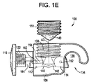
図1A〜1Eは、脊椎コネクター100の例示的な一実施形態を示す。コネクター100は一般に、第1の脊椎固定エレメント102と、第1の脊椎固定エレメント102を第2の脊椎固定エレメント106に連結するための接続アセンブリ104とを含む。第2の脊椎固定エレメント106は以前に埋め込まれた脊椎固定エレメントであってよく、これに対してコネクター100が連結されていてもよく、又は、コネクター100と共に若しくはコネクター100と同じ手順の一部として埋め込むことができる。接続アセンブリ104は、接続アセンブリ104に対する第1の脊椎固定エレメント102の向きを選択的にロックし、かつ第2の脊椎固定エレメント106に対する接続アセンブリの位置及び向きロックするためのロック機構を含む。図示のように、接続アセンブリ104は、ハウジング108、止めねじ110、第1及び第2のシュー112、114、並びに保持キャップ116を含み得る。
1A-1E illustrate an exemplary embodiment of a
図示の実施形態において、第1及び第2の脊椎固定エレメント102、106は細長い脊椎ロッドであるが、代わりに又は追加として、例えば骨プレートなどの、様々な固定エレメントの任意のものを使用できることが理解されよう。第1の脊椎固定エレメント102は、第1の脊椎固定エレメントをハウジング108に対して回転可能に連結するよう構成された、それ自体に形成されているか又はその第1の末端に連結された、嵌合機構118を含み得る。図示の実施形態において、嵌合機構118は、第1の脊椎固定エレメント102と共に一体形成された環形構造である。嵌合機構118は、ハウジング108から横方向外向きに延出するポスト122を受容するよう構成された中央開口部120を含み得、これによって、嵌合機構はポストを中心に(例えば、ポストの長手方向軸を中心に)回転可能である。換言すれば、ハウジング108は中央開口部120の長手方向軸A1を中心に回転可能であり得る。第1の脊椎固定エレメント102の、反対側の第2の末端124は、第1の脊椎固定エレメントの低侵襲性挿入を容易にするよう構成され得る。例えば、第2の末端124は、挿入ポータルから最終的埋込位置への皮下の第1の脊椎固定エレメント102の無外傷的トンネル形成を可能にするよう、丸くなっていても、弾丸状であっても、先細状などであってもよい。
In the illustrated embodiment, the first and second
第1の脊椎固定エレメント102は、完全に真っ直ぐであってよく、又は1つ若しくは2つ以上の屈曲、湾曲、継手、ずれ、突出などを含み得る。例えば、第1の脊椎固定エレメント102は、患者の解剖学的構造に対し、又はコネクター100を連結する固定構築物の部分(例えば、骨ねじ)のための、クリアランスを提供するために、S字形又はZ字形の屈曲を有し得る。図示の実施形態において、第1の脊椎固定エレメント102は、湾曲部分128により嵌合機構118に接合された真っ直ぐな部分126を含む。湾曲部分128は、第1の脊椎固定エレメント102が、患者の解剖学的構造の一部分の回り、又はコネクター100が連結される固定構築物の一部分の回りで屈曲できるように、ずれを提供し得る。したがって、ロープロファイルな構築物が形成され、第1の脊椎固定エレメント102の真っ直ぐな部分126は、第2の脊椎固定エレメント106の自然な延長部となる。よって、コネクター100は、第1の脊椎固定エレメント102が骨アンカーを妨げることなしに、第2の脊椎固定エレメントの第1の骨アンカーと第2の骨アンカーとの中間で、以前に設置された第2の脊椎固定エレメント106上にクランプ固定可能であることが理解されよう。第1の脊椎固定エレメント102は剛性であっても、又は屈曲可能であっても、若しくは柔順性であってもよく、又は剛性部分と屈曲可能部分の両方を含んでもよい。よって、いくつかの実施形態において、第1の脊椎固定エレメント102の外形は、手作業で、又は曲げ工具の助けを借りて、具体的な手順の必要に応じて調整することができる。
The first
保持キャップ116は、第1の脊椎固定エレメント102の嵌合機構118を、ハウジング108のポスト122上に保持し、同時に、第1の脊椎固定エレメントが依然としてポストを中心に回転できるように構成することができる。保持キャップ116は、それ自体から延出するピン132を備えた円板形カバー130を含み得る。ピン132は、ハウジング108のポスト122内に受容され、ハウジングとカバー130との間に嵌合機構118を捕捉することができる。ピン132の外側とポスト122の内側は、互いにねじで係合するための対応するねじ山を含み得る。ねじ係合が図示されているが、保持キャップ116をハウジング108に連結するのに、様々な他の技法の任意のものが使用可能であることが理解されよう。例えば、ピン132は、ポスト122に対して、押し嵌め、溶接、横ピン止め、及び/又は接着することができる。
The
ハウジング108はクランプ部分134を含み得、この中に第2の脊椎固定エレメント106が受容され得る。クランプ部分134は、ポスト122が延在しているハウジング108の側面とは反対側のハウジング側面上に形成され得る。あるいは、クランプ部分134は、ポスト122が延在している側面に隣接した側面上に形成され得る。
The
クランプ部分134は、コネクター100が連結される第2の脊椎固定エレメント106に応じた寸法及び/又は形状にされた陥凹部136を含み得る。例えば、陥凹部136の直径は、第2の脊椎固定エレメント106の直径に実質的に等しくてよい。あるいは、陥凹部136の直径は第2の脊椎固定エレメント106の直径よりわずかに小さくてもよく、これによって、コネクター100が第2の脊椎固定エレメントに「スナップ嵌め」したときに外科医に触覚的フィードバック及び/又は聴覚的フィードバックを提供するスナップ嵌め係合が可能になる。下記で詳しく検討されるように、このフィードバックは特に低侵襲性再置換手術で有利であり得る。別の代替例として、陥凹部136の直径は第2の脊椎固定エレメント106の直径よりわずかに大きくてもよく、下記で述べるように、コネクター100のロック機構が作動するときに第2のシュー114により引き締められる任意のあそびを備えることができる。よって、脊椎コネクター100は、様々な寸法又は形状の第2の脊椎固定エレメントに連結するよう構成され得る。いくつかの実施形態において、それぞれ異なる寸法又は形状の陥凹部136を有し得る複数の脊椎コネクター100が、キットの一部として提供され、これによって具体的な用途に対して適切な寸法及び形状のコネクターを選択することが可能になる。
The
図示の陥凹部136は、円筒形の一部分を形成しているが、この陥凹部は、コネクター100が連結される第2の脊椎固定エレメント106の形状に応じて、様々な他の形状を有し得ることが理解されよう。例えば、長方形の断面を有する第2の脊椎固定エレメント106の場合、陥凹部136は対応する長方形形状を有し得る。
The illustrated
陥凹部136は、中央開口部120の長手方向軸A1に対して垂直に延在する長手方向軸A2を有し得る。よって、陥凹部136の長手方向軸A2は、第1の脊椎固定エレメント102がハウジング108に対して回転する回転軸に対して垂直であり得る。そのような実施形態において、第2の脊椎固定エレメント106が陥凹部136内に受容されるとき、第1の脊椎固定エレメント102は、第2の脊椎固定エレメント106の長手方向軸に対して垂直な軸を中心に回転可能であり得る。陥凹部136を画定するハウジング108のクランプ部分134は、第2の脊椎固定エレメント106の任意の部分の回りに延在するよう構成し得る。図示の実施形態において、クランプ部分134は、第2の脊椎固定エレメント106の周囲の約200度にわたって延在するような寸法にされている。他の実施形態において、クランプ部分134は、第2の脊椎固定エレメント106の周囲の、これより大きい又は小さい範囲を覆うことができる。例えば、被覆範囲は、第2の脊椎固定エレメント106の周囲の約160度〜約240度であり得る。
The
ハウジング108は、ロックエレメントが受容される開口部を含み得る。例えば、図示のように、ハウジング108は、外側にねじ山のある止めねじ110を受容するよう構成された、内側にねじ山のある穴138を含み得る。図1Eで最もよくわかるように、ハウジング108は更に第1及び第2のチャンネル140、142を含み得、この中に、第1及び第2のシュー112、114がそれぞれ、摺動可能に受容される。第1のチャンネル140は、ねじ山のある穴138から、ポスト122内に形成された側壁開口部144まで延在し得る。図1Dで最もよくわかるように、第2のチャンネル142は陥凹部136内に向かって開いていてよく、陥凹部からねじ山のある穴138まで延在し得る。
The
第1のシュー112は、第1のシューがポスト122を通って突出する延長位置と、第1のシューがポストを通って突出していない、又はポストを通って突出する度合が少ない、後退位置との間で、第1のチャンネル140内で摺動可能であり得る。延長位置において、第1のシュー112は嵌合機構118の内壁に係合して、ポスト122を中心とした第1の脊椎固定エレメント102の回転に抵抗すること又はこれを阻止することができる。後退位置において、第1のシュー112は嵌合機構118に係合していないか、又は軽い係合のみであるため、第1の脊椎固定エレメント102はポスト122を中心に自由に回転可能である。嵌合機構118に係合するよう構成された第1のシュー112の表面は、嵌合機構の引っかかり強化を提供するため、歯、鋸歯、又はその他の把持特徴若しくは表面処理を含み得る。ロックエレメントが係合するよう構成された、第1のシュー112の反対側の面は、ロックエレメントの形状に一致するような、及び、ロックエレメントが開口部138内で前進するときに第1のシューの摺動を促進するような、形状にすることができる。例えば、第1のシュー112は、ロックエレメント110の凸状遠位先端148に一致するような寸法にされた、斜面又は凹面146を画定し得る。
The
第2のシュー114は、第2のシューが陥凹部136を入って突出する延長位置と、第2のシューが陥凹部を入って突出していない、又は陥凹部を入って突出する度合が少ない、後退位置との間で、第2のチャンネル142内で摺動可能であり得る。延長位置において、第2のシュー114は、陥凹部136内に配置された第2の脊椎固定エレメント106に係合して、コネクター100を第2の脊椎固定エレメントに対してクランプ固定することができ、これにより、これら2つの間の相対的な動き(例えば、回転及び/又は長手方向並進)に抵抗すること又はこれを阻止することができる。後退位置において、第2のシュー114は陥凹部136内の第2の脊椎固定エレメント106の位置決めを妨げず、これによって、コネクター100は第2の脊椎固定エレメント106に沿って望ましい位置に摺動し、かつ、第2の脊椎固定エレメント106を中心に望ましい向きに回転することができる。第2の脊椎固定エレメント106に係合するよう構成された第2のシュー114の表面は、第2の脊椎固定エレメントのタイプに従った形状にすることができる。例えば、コネクター100が円筒形固定ロッドに連結される場合、その表面はロッドの半径に一致する曲率半径か、又はロッドの半径に実質的に一致する(すなわち、若干小さい若しくは大きい)曲率半径を有し得る。この表面は、第2の脊椎固定エレメント106との引っかかり強化を提供するため、歯、鋸歯、又はその他の把持特徴若しくは表面処理を含み得る。ロックエレメントが係合するよう構成された、第2のシュー114の反対側の面は、ロックエレメントの形状に一致するような、及びロックエレメントが開口部138内で前進するときに第2のシューの摺動を促進するような、形状にすることができる。例えば、第2のシュー114は、ロックエレメント110の凸状遠位先端148に一致するような寸法にされた、斜面又は凹面150を画定し得る。
The
ハウジング108は、第1及び/又は第2のシュー112、114の行程を制限するよう構成された1本又は2本以上の保持ピン152を含み得る(例えば、シューが誤ってコネクター100から落ちるのを防止するため)。図示の実施形態において、ピン152はハウジング108の第1及び第2のチャンネル140、142内へと延在し、第1及び第2のシュー112、114内に形成されたスロット又は溝154内に摺動可能に受容される。
The
ロックエレメント110が開口部内で前進すると、第1のシュー112に係合して、第1のシューを第1のチャンネル140内で摺動させ、第1の脊椎固定エレメント102の嵌合機構118の内壁と係合させることができる。同時に、ロックエレメント110は第2のシュー114に係合し、第2のシューを第2のチャンネル142内で摺動させ、陥凹部136内に配置された第2の脊椎固定エレメント106と係合させることができる。図示の実施形態において、第1及び第2のチャンネル140、142は開口部138から下向き及び横方向外向きに延在し、これにより、第1及び第2のシュー112、114は後退位置と延長位置との間の線形経路に沿って並進運動する。他の実施形態において、第1及び第2のチャンネル140、142のうち一方又は両方が、下向きのみ又は外向きのみに延在し得る。また更なる実施形態において、第1及び第2のシュー112、114は、線形並進運動なしで、又は線形並進運動との組み合わせで、延長位置と後退位置との間で回転するよう構成することができる。例えば、第1及び第2のシュー112、114は、延長位置と後退位置との間でハウジング108に対して回転可能となるように、それぞれの枢動ピン上に取り付けることができる。
As the
任意の様々なロックエレメントを使用することができるが、図示の実施形態において、ロックエレメントは、外側にねじ山のある止めねじ110を含む。止めねじ110は、開口部138の対応する内側のねじ山にねじで係合することができ、これにより、止めねじの第1の方向の回転は、止めねじをハウジング108内で前進させるのに有効であり、また、止めねじの第2の方向(反対方向)の回転は、止めねじをハウジングに対して後退させるのに有効である。開口部の長手方向軸A3は、陥凹部の長手方向軸A2に対して垂直で、かつ、ポスト122を中心とした第1の脊椎固定エレメント102の回転軸に対して(例えば、中央開口部120の長手方向軸A1に対して)垂直に延在し得る。止めねじ110の長さは、開口部138の深さに実質的に等しくてよく、これにより、開口部に完全に収容されているとき、止めねじの上表面は、ハウジング108の上表面と同一面になって収まる。止めねじ110は、この止めねじを回転させるためのドライバー、レンチ、又はその他の器具を受容又はこれに係合するよう構成された駆動界面156を含み得る。止めねじ110の遠位先端148は、第1及び第2のシュー112、114に係合するための係合表面を含み得る。例えば、止めねじ110の遠位先端148は、円錐形、先細、弾丸状、凸状などであってよく、これにより、第1及び第2のシュー112、114に対して押し付けられるカム表面を提供して、シューをそれぞれの延長位置へと押しやる。図には単一の止めねじ110が示されているが、コネクター100は複数の止めねじを含み得ることが理解されよう(例えば、第1の止めねじは、第1のシュー112に係合して、第1の脊椎固定エレメント102のハウジング108に対する回転を選択的にロックするよう構成され、第2の止めねじは、第2のシュー114に係合して、ハウジング108を第2の脊椎固定エレメント106に対して選択的にクランプ止めするよう構成される)。
Although any of a variety of locking elements can be used, in the illustrated embodiment, the locking element includes a
使用中、脊椎コネクター100は(例えば、下記で詳しく検討するように低侵襲性技法を使用して)手術部位内に位置決めすることができる。以前に設置された第2の脊椎固定エレメント106を陥凹部136内に位置決めすることができ、ハウジング108を第2の脊椎固定エレメント106に対して望ましい位置及び/又は向きに動かすことができる。加えて、第1の脊椎固定エレメント102を望ましい位置まで回転させることができる。止めねじ110を締めると、第1及び第2のシュー112、114が、それぞれ第1及び第2のチャンネル140、142内で押しやられ、それぞれ嵌合機構118及び第2の脊椎固定エレメント106に係合し得る。第1のシュー112は嵌合機構118に係合して、第1の脊椎固定エレメント102のハウジング108に対する回転位置をロックすることができる。同時に、又は実質的に同時に、第2のシュー114は第2の脊椎固定エレメント106に係合して、ハウジング108をそこにクランプ止めし、第2の脊椎固定エレメント106に対するハウジング108の位置及び向きをロックすることができる。このように、単一のロック機構の作動は、(1)コネクターに回転可能に連結された第1の脊椎固定エレメントの向きをロックすること、及び(2)第2の脊椎固定エレメントに対するコネクターの位置及び向きをロックすることの両方について、有効であり得る。第2の脊椎固定エレメントのロックと、コネクターの1つ又は2つ以上の自由度のロックという、この複数の機能性は、単一のロック機構のためのアクセスのみが必要であり、また一工程で2つ以上の機能を実施することが可能になるため、低侵襲性手術において特に有利であり得る。
In use, the
脊椎コネクター100は、任意の様々な向きで第2の脊椎固定エレメント106に連結され得る。例えば、脊椎コネクター100は、止めねじ110の駆動界面156が患者の後側方向を向き、かつ、止めねじを前後軸に沿って前進させてコネクターをロックするように、第2の脊椎固定エレメント106に連結され得る。更なる例として、脊椎コネクター100は、止めねじ110の駆動界面156が患者に対して内側又は外側方向を向き、かつ、止めねじを内外軸に沿って前進させてコネクターをロックするように、第2の脊椎固定エレメント106に連結され得る。脊椎コネクター100は更に、上記の2つの例の間の任意の向きで、及び第2の脊椎固定エレメントの長さに沿った任意の点で、第2の脊椎固定エレメント106に連結され得る。
The
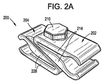
図2A〜2Hは、脊椎コネクター200の別の例示的な一実施形態を示す。コネクターは、第1及び第2の脊椎固定エレメント206、208をそれぞれ把持するよう構成された第1及び第2のクランプ部材202、204を含み得る。コネクター200は更に、第1及び第2のクランプ部材202、204を第1及び第2の脊椎固定エレメント206、208に対して選択的にロックし、またコネクター200の1つ又は2つ以上の自由度をロックするよう構成された、ロック機構(例えば、図示のロックボルト210及びロックナット212)を含み得る。
2A-2H illustrate another exemplary embodiment of a
第1のクランプ部材202は、丁番部分216で互いに連結された相対するアーム214を含み得る。一体丁番216が図示されているが、様々な任意の丁番機構を使用できることが理解されよう。例えば、相対するアーム214は、枢動ピンを中心に互いに回転可能に連結され得る。相対するアーム214はそれぞれ、陥凹部220が第1の脊椎固定エレメント206を受容するよう形成されている嵌合部分218を含み得る。相対するアーム214はそれぞれ、更に、丁番部分216と嵌合部分218との間に配置された主部分222を含み得る。相対するアーム214は、ロック解除位置に位置決めすることができ、この位置で、アームの主部分222の間に画定されたスロット224は、実質的に平行な側壁を有し、かつ、第1のクランプ部材202は、アームの嵌合部分218の間に配置された第1の脊椎固定エレメント206に対して可動である。相対するアーム214は更に、ロック位置に位置決めすることができ、この位置で、アームの主部分222は丁番部分216を中心に互いに向かって屈曲され、かつ、アームの嵌合部分218の間に配置された第1の脊椎固定エレメント206は第1のクランプ部材202に対してロックされ、これにより、第1の脊椎固定エレメントの第1のクランプ部材に対する回転又は摺動運動に抵抗又はこれを阻止する。
The
嵌合部分218はそれらの間に、第1のクランプ部材202が連結される第1の脊椎固定エレメント206に応じた寸法及び/又は形状にされた陥凹部220を画定し得る。例えば、陥凹部220の直径は、第1の脊椎固定エレメント206の直径に実質的に等しくてよい。あるいは、陥凹部220の直径は第1の脊椎固定エレメント206の直径よりわずかに小さくてもよく、これによって、第1のクランプ部材202が脊椎固定エレメント206に「スナップ嵌め」したときに外科医に触覚的フィードバック及び/又は聴覚的フィードバックを提供するスナップ嵌め係合が可能になる。下記で詳しく検討されるように、このフィードバックは特に低侵襲性再置換手術で有利であり得る。別の代替例として、陥凹部220の直径は、コネクター200が連結される第1の脊椎固定エレメント206の直径よりわずかに大きくてもよく、ロックボルト210とロックナット212が締められたときに、クランプ動作により引き締められる任意のあそびを備えることができる。第1のクランプ部材202は、よって、様々な寸法又は形状の第1の脊椎固定エレメントに連結するよう構成され得る。いくつかの実施形態において、それぞれ異なる寸法又は形状の陥凹部220を有し得る複数のクランプ部材202が、キットの一部として提供され、これによって具体的な用途に対して適切な寸法及び形状のクランプ部材を選択することが可能になる。
The
図示の陥凹部220は、円筒形の一部分を形成しているが、この陥凹部は、第1のクランプ部材202が連結される第1の脊椎固定エレメント206の形状に応じて、様々な他の形状を有し得ることが理解されよう。例えば、長方形の断面を有する第1の脊椎固定エレメント206の場合、陥凹部220は対応する長方形形状を有し得る。図2Hに示すように、陥凹部220は平坦又は平面状の側壁により画定されてよく、これらは、少なくともいくつかの例において、より幅広い範囲の固定エレメントの寸法及び形状に対して、表面接触を増大させることができる。
The illustrated
図2Gに示すように、陥凹部220は、ロックボルトが第1のクランプ部材202を通って延在するとき、ロックボルト210の長手方向軸A2に対して垂直に延在する長手方向軸A1を有し得る。よって、陥凹部220の長手方向軸A1は、第1のクランプ部材202がロックボルト210に対して回転する回転軸A2に対して垂直であり得る。アーム214の嵌合部分218は、第1の脊椎固定エレメント206の任意の部分の回りに延在するよう構成し得る。図示の実施形態において、アーム214は全体として、第1の脊椎固定エレメント206の周囲の約180度にわたって延在する。他の実施形態において、アーム214は、第1の脊椎固定エレメント206の周囲の、これより大きい又は小さい範囲を覆うことができる。例えば、被覆範囲は、第1の脊椎固定エレメント206の周囲の約90度〜約270度であり得る。
As shown in FIG. 2G, the
同軸開口部226は、第1のクランプ部材202の相対するアーム214内に形成されてよく、これによりロックボルト210は相対するアームを通って延在し得る。第1のクランプ部材202は、ロックボルト210が相対するアーム214を通って配置され、かつロックボルトとロックナット212を締める前に、ロックボルト210の長手方向軸A2を中心に回転可能であり得る。開口部226の1つ又は2つ以上の内部寸法は、ロックボルト210の対応する外部寸法よりも大きくてよく、これにより、相対するアーム214を通ってロックボルトが配置され、かつ、ロックボルトとロックナット212を締める前に、第1のクランプ部材202をロックボルトに対して1つ又は2つ以上の方向に並進運動させることができる。例えば、図示のように、開口部226は長円形であってよく、ロックボルト210の外側直径よりも大きい長軸と、ロックボルトの外側直径に実質的に等しい短軸とを有し得る。したがって、第1のクランプ部材202は、ロックボルト210に対して、図2Dの第1のクランプ部材に示されているX方向及びZ方向にのみ並進運動できる。更なる例として、開口部226は円形であってよく、ロックボルト210の外側直径よりも大きい内側直径を有し得、これにより、第1のクランプ部材202は、ロックボルトに対して、図2Dの第1のクランプ部材に示されているX、Y、及びZ方向に並進運動できる。
A
第2のクランプ部材204は、丁番部分230で互いに連結された相対するアーム228を含み得る。一体丁番230が図示されているが、様々な任意の丁番機構を使用できることが理解されよう。例えば、相対するアーム228は、枢動ピンを中心に互いに回転可能に連結され得る。相対するアーム228はそれぞれ、陥凹部234が第2の脊椎固定エレメント208を受容するよう形成されている嵌合部分232を含み得る。相対するアーム228はそれぞれ、更に、丁番部分230と嵌合部分232との間に配置された主部分236を含み得る。相対するアーム228は、ロック解除位置に位置決めすることができ、この位置で、アーム228の主部分236の間に画定されたスロット238は、実質的に平行な側壁を有し、かつ、第2のクランプ部材204は、アーム228の嵌合部分232の間に配置された第2の脊椎固定エレメント208に対して可動である。相対するアーム228は更に、ロック位置に位置決めすることができ、この位置で、アームの主部分236は丁番部分230を中心に互いに向かって屈曲され、かつ、アームの嵌合部分232の間に配置された第2の脊椎固定エレメント208は第2のクランプ部材204に対してロックされ、これにより、第2の脊椎固定エレメントの第2のクランプ部材に対する回転又は摺動運動に抵抗し又はこれを阻止する。
The
嵌合部分232はそれらの間に、第2のクランプ部材204が連結される第2の脊椎固定エレメント208に応じた寸法及び/又は形状にされた陥凹部234を画定し得る。例えば、陥凹部234の直径は、第2の脊椎固定エレメント208の直径に実質的に等しくてよい。あるいは、陥凹部234の直径は第2の脊椎固定エレメント208の直径よりわずかに小さくてもよく、これによって、第2のクランプ部材204が第2の脊椎固定エレメントに「スナップ嵌め」したときに外科医に触覚的フィードバック及び/又は聴覚的フィードバックを提供するスナップ嵌め係合が可能になる。下記で詳しく検討されるように、このフィードバックは特に低侵襲性再置換手術で有利であり得る。別の代替例として、陥凹部234の直径は、コネクター200が連結される第2の脊椎固定エレメント208の直径よりわずかに大きくてもよく、ロックボルト210とロックナット212が締められたときに、クランプ動作により引き締められる任意のあそびを備えることができる。第2のクランプ部材204は、よって、様々な寸法又は形状の第2の脊椎固定エレメントに連結するよう構成され得る。いくつかの実施形態において、それぞれ異なる寸法又は形状の陥凹部234を有し得る複数のクランプ部材204が、キットの一部として提供され、これによって具体的な用途に対して適切な寸法及び形状のクランプ部材を選択することが可能になる。
The
図示の陥凹部234は、円筒形の一部分を形成しているが、この陥凹部は、第2のクランプ部材204が連結される第2の脊椎固定エレメント208の形状に応じて、様々な他の形状を有し得ることが理解されよう。例えば、長方形の断面を有する第2の脊椎固定エレメント208の場合、この陥凹部は対応する長方形形状を有し得る。図2Hに示すように、陥凹部234は平坦又は平面状の側壁により画定されてよく、これらは、少なくともいくつかの例において、より幅広い範囲の固定エレメントの寸法及び形状に対して、表面接触を増大させることができる。
The illustrated
図2Gに示すように、陥凹部234は、ロックボルト210が第2のクランプ部材204を通って延在するとき、ロックボルトの長手方向軸A2に対して垂直に延在する長手方向軸A3を有し得る。よって、陥凹部234の長手方向軸A3は、第2のクランプ部材204がロックボルト210に対して回転する回転軸A2に対して垂直であり得る。アーム228の嵌合部分232は、第2の脊椎固定エレメント208の任意の部分の回りに延在するよう構成され得る。図示の実施形態において、アーム228は全体として、第2の脊椎固定エレメント208の周囲の約180度にわたって延在する。他の実施形態において、アーム228は、第2の脊椎固定エレメント208の周囲の、これより大きい又は小さい範囲を覆うことができる。例えば、被覆範囲は、第2の脊椎固定エレメント208の周囲の約90度〜約270度であり得る。
As shown in FIG. 2G, the
同軸開口部240は、第2のクランプ部材204の相対するアーム228内に形成されてよく、これによりロックボルト210は相対するアームを通って延在し得る。第2のクランプ部材204は、ロックボルト210が相対するアーム214を通って配置され、かつロックボルトとロックナット212を締める前に、ロックボルトの長手方向軸A2を中心に回転可能であり得る。開口部240の1つ又は2つ以上の内部寸法は、ロックボルト210の対応する外部寸法よりも大きくてよく、これにより、相対するアーム228を通ってロックボルトが配置され、かつ、ロックボルトとロックナット212を締める前に、第2のクランプ部材204をロックボルトに対して1つ又は2つ以上の方向に並進運動させることができる。例えば、図示のように、開口部240は長円形であってよく、ロックボルト210の外側直径よりも大きい長軸と、ロックボルトの外側直径に実質的に等しい短軸とを有し得る。したがって、第2のクランプ部材204は、ロックボルト210に対して、図2Dの第2のクランプ部材に示されているX方向及びZ方向にのみ並進運動できる。更なる例として、開口部240は円形であってよく、ロックボルト210の外側直径よりも大きい内側直径を有し得、これにより、第2のクランプ部材204は、ロックボルトに対して、図2Dの第2のクランプ部材に示されているX、Y、及びZ方向に並進運動できる。
A
第1のクランプ部材202は、第1及び第2のクランプ部材がロックボルト210を介して互いに係合しているとき、第2のクランプ部材204の平面状の下表面244に対して実質的に平行になるように構成されている平面状の上表面242を含み得る。第1のクランプ部材202は、第1のクランプ部材202の平面状の上表面242に対して斜めの角度で延在する平面状の下表面246を含み得る。第2のクランプ部材204は、第2のクランプ部材204の平面状の下表面244に対して斜めの角度で延在する平面状の上表面248を含み得る。球形又は長円体の突出部250が、第1のクランプ部材202の下表面246表面に形成されてよく、これは、第2のクランプ部材204の上表面248に形成された対応する球形又は長円体の陥凹部252に収容され得る。第1のクランプ部材202と第2のクランプ部材204との間の湾曲した界面は、第1及び第2のクランプ部材が互いに対して回転及び/又は並進運動するときの、制限された接触の滑り運動を容易にし得る。いくつかの実施形態において、突出部250は、第2のクランプ部材204に形成されてよく、陥凹部252は第1のクランプ部材202に形成され得ることが、理解されよう。
The
任意の様々なロック機構を使用することができるが、図示の実施形態において、ロック機構はロックボルト210及びロックナット212を含む。ロックボルト210は、頭部254及び細長いシャンク部分256を含み得る。頭部254は、ロックボルト210を締める又は緩めるのを容易にするため、レンチで把持するための切子面の外側表面を有し得る。あるいは、又は加えて、頭部254はメス陥凹部を含み得、ドライバー又はその他の器具がここに受容されて、ロックボルト210を回転させ、これを締めること又は緩めることができる。ロックボルト210のシャンク256は、その長さ全体にわたって、又はその長さの一部分のみに沿って、ねじ山を有し得る。ねじ山を有するシャンク256は、ロックナット212のねじ山を有する内面内に受容されてよく、これによって、ロックボルト210のロックナットに対する第1の方向の回転は、ロックボルトの頭部254に向かってナットを移動させるのに有効であり、第2の方向(反対方向)の相対的な回転は、ロックボルトの頭部からロックナットを離すように押しやるのに有効である。ロックナット212の少なくとも一部分は、第2のクランプ部材204内に非回転的に受容され得る。例えば、ロックナット212は、第2のクランプ部材204の下側アームの長円形開口部240に受容されるよう構成された長円形部分258を有し得る。ロックナット212の長円形の部分258の長軸は、長円形開口部240の長軸よりも小さくてよく、これにより第2のクランプ部材204は、ロックナットがその中に受容されているときに、ロックナットに対して少なくとも一方向に並進運動することができる。
Although any of a variety of locking mechanisms can be used, in the illustrated embodiment, the locking mechanism includes a
ロックナット212は、第2のクランプ部材204内に受容されるよう構成することができ、これによりロックナットは、第2のクランプ部材の平面状の下表面244と同一面、又は同一面より下になるよう収まるか、又は図示のように飛び出して収まる。ロックボルト210の頭部254は、図示の実施形態において、第1のクランプ部材202の平面状の上表面242から飛び出して収まっているものとして示されているが、この頭部は、面取り、皿穴、又は締めたときに、第1のクランプ部材の上表面と同一面、又は同一面より下になるよう構成され得る。いくつかの実施形態において、ロックナットは省略することができ、ロック機構は、第1及び/又は第2のロック部材の1つ又は2つ以上のアーム(例えば、第2のロック部材の下側アーム)内に形成されたねじ山のある開口部に、ねじで係合するよう構成されたロックねじを含み得る。
The
使用中、脊椎コネクター200は(例えば、下記で詳しく検討するように低侵襲性技法を使用して)手術部位内に位置決めすることができる。第1の脊椎固定エレメント206は、第1のクランプ部材202の陥凹部220内で位置決めすることができ、また第2の脊椎固定エレメント208は、第2のクランプ部材204の陥凹部234内で位置決めすることができる。第1及び第2のクランプ部材202、204は、互いに対して、及び/又はロック機構に対して、並進運動すること及び/又は回転することができ、これにより第1及び第2の脊椎固定エレメント206、208を望ましい相対的配列にすることができる。脊椎コネクター200により提供される複数の自由度は、第1及び第2の脊椎固定エレメント206、208が互いに平行ではない場合に、特に有利であり得る。ロックボルト210を締めると、第1及び第2のクランプ部材202、204がそれぞれの丁番部分216、230で屈曲してそれぞれのロック構成になり、第1及び第2の脊椎固定エレメント206、208に対してクランプ止めを行い、コネクター200に対してロックする。同時に、第1及び第2のクランプ部材202、204は圧搾されて互いに対してしっかりと係合し、第1及び第2のクランプ部材が互いに対して回転すること、及び/又は互いに対して1つ又は2つ以上の方向に並進運動することに対して、抵抗し又はこれを阻止する。このように、単一のロック機構の作動は、(1)第1のクランプ部材を第1の脊椎固定エレメントに対してロックすること、(2)第2のクランプ部材を第2の脊椎固定エレメントに対してロックすること、(3)第1のクランプ部材と第2のクランプ部材との間の回転自由度をロックすること、並びに(4)第1のクランプ部材と第2のクランプ部材との間の1つ又は2つ以上の並進自由度をロックすること、について有効であり得る。複数の脊椎固定エレメントのロックと、コネクターの1つ又は2つ以上の自由度のロックという、この複数の機能性は、単一のロック機構のためのアクセスのみが必要であり、また一工程で2つ以上の機能を実施することが可能になるため、低侵襲性手術において特に有利であり得る。
In use, the
脊椎コネクター200は、任意の様々な向きで脊椎固定エレメント206、208に連結され得る。例えば、脊椎コネクター200は、共通の冠状面内に実質的にある第1及び第2の脊椎固定エレメント206、208に連結され、これによって、ロックボルト210は、患者の前後軸又は矢状軸に沿って延在する。更なる例として、脊椎コネクター200は、共通の矢状面内に実質的にある第1及び第2の脊椎固定エレメント206、208に連結され、これによって、ロックボルトは、患者の内外軸又は横断軸に沿って延在する。脊椎コネクター200は更に、上述の2つの例の間の任意の向きで、及び脊椎固定エレメントの長さに沿った任意の点で、脊椎固定エレメント206、208に連結され得る。第1及び第2の脊椎固定エレメント206、208は、共通の面内にある必要はない。
The
図示の実施形態において、第1及び第2の脊椎固定エレメント206、208は細長い脊椎ロッドであるが、代わりに又は追加として、例えば骨プレートなどの、様々な固定エレメントの任意のものを使用できることが理解されよう。第1及び第2の脊椎固定エレメント206、208は、上述のように、完全に真っ直ぐであってよく、又は1つ若しくは2つ以上の屈曲、湾曲、継手、ずれ、突出などを含み得る。
In the illustrated embodiment, the first and second
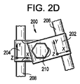
図3A〜3Eは、脊椎コネクター300の別の例示的な一実施形態を示す。コネクター300は一般に、第1の脊椎固定エレメント302と、第1の脊椎固定エレメント302を第2の脊椎固定エレメント306に連結するための接続アセンブリ304とを含む。第2の脊椎固定エレメント306は以前に埋め込まれた脊椎固定エレメントであってよく、これに対してコネクター300が連結されていてもよく、又は、コネクター300と共に若しくはコネクター300と同じ手順の一部として埋め込むことができる。接続アセンブリ304は、接続アセンブリ304に対する第1の脊椎固定エレメント302の向きを選択的にロックし、かつ第2の脊椎固定エレメント306に対する接続アセンブリの位置及び向きロックするためのロック機構を含む。図示のように、接続アセンブリ304は、上側クランプアーム308、下側クランプアーム310、付勢エレメント312、及びロックエレメント314を含み得る。
3A-3E illustrate another exemplary embodiment of a
図示の実施形態において、第1及び第2の脊椎固定エレメント302、306は細長い脊椎ロッドであるが、代わりに又は追加として、例えば骨プレートなどの、様々な固定エレメントの任意のものを使用できることが理解されよう。第1の脊椎固定エレメント302は、第1の脊椎固定エレメントを接続アセンブリ304に対して回転可能に連結するよう構成された、それ自体に形成されているか又はその第1の末端に連結された、嵌合機構318を含み得る。図示の実施形態において、嵌合機構318は、第1の脊椎固定エレメント302と共に一体形成された環形構造である。嵌合機構318は、それ自体の中を通してロックエレメントを受容するよう構成された中央開口部320を含み得、これによって、ロックエレメントのねじ山のない部分が中央開口部320内に配置され、ロックエレメントが締められない限り、第1の脊椎固定エレメント302がロックエレメントを中心に自由に回転可能である(例えば、ロックエレメントの長手方向軸を中心に回転可能)。換言すれば、接続アセンブリ304は中央開口部320の長手方向軸A1を中心に回転可能であり得る。第1の脊椎固定エレメント302の、反対側の第2の末端324は、第1の脊椎固定エレメントの低侵襲性挿入を容易にするよう構成され得る。例えば、第2の末端324は、挿入ポータルから最終的埋込位置への皮下の第1の脊椎固定エレメント302の無外傷的トンネル形成を可能にするよう、丸くなっていても、弾丸状であっても、先細状などであってもよい。
In the illustrated embodiment, the first and second
第1の脊椎固定エレメント302は、完全に真っ直ぐであってよく、又は1つ若しくは2つ以上の屈曲、湾曲、継手、ずれ、突出などを含み得る。例えば、第1の脊椎固定エレメント302は、患者の解剖学的構造に対し、又はコネクター300を連結する固定構築物の部分(例えば、骨ねじ)のための、クリアランスを提供するために、S字形又はZ字形の屈曲を有し得る。図示の実施形態において、第1の脊椎固定エレメント302は、湾曲部分328により嵌合機構318に接合された真っ直ぐな部分326を含む。湾曲部分328は、第1の脊椎固定エレメント302が、患者の解剖学的構造の一部分の回り、又はコネクター300が連結される固定構築物の一部分の回りで屈曲できるように、ずれを提供し得る。したがって、ロープロファイルな構築物が形成され、第1の脊椎固定エレメント302の真っ直ぐな部分326は、第2の脊椎固定エレメント306の自然な延長部となる。よって、コネクター300は、第1の脊椎固定エレメント302が骨アンカーを妨げることなしに、第2の脊椎固定エレメントの第1の骨アンカーと第2の骨アンカーとの中間で、以前に設置された第2の脊椎固定エレメント306上にクランプ固定可能であることが理解されよう。第1の脊椎固定エレメント302は剛性であっても、又は屈曲可能であっても、若しくは柔順性であってもよく、又は剛性部分と屈曲可能部分の両方を含んでもよい。よって、いくつかの実施形態において、第1の脊椎固定エレメント302の外形は、手作業で、又は曲げ工具の助けを借りて、具体的な手順の必要に応じて調整することができる。
The first
上側クランプアーム308は長方形の陥凹部330を含み得、下側クランプアーム310に形成された対応する長方形突出部332がこの中に受容されてよく、これにより、上側及び下側クランプアームが合わせて丁番接合され、互いに対して枢動し得る。他の実施形態において、上述の配置を逆にして、下側クランプアーム310が陥凹部330を含み、上側クランプアーム308が突出部332を含むようにできることが理解されよう。
The
上側及び下側クランプアーム308、310はそれぞれ更に、第2の脊椎固定エレメント306を受容するための嵌合部分334を含み得る。上側及び下側クランプアーム308、310の嵌合部分334は合わせて、それらの間に、コネクター300が連結される第2の脊椎固定エレメント306に応じた寸法及び/又は形状にされた陥凹部336を画定し得る。例えば、陥凹部336の直径は、第2の脊椎固定エレメント306の直径に実質的に等しくてよい。あるいは、陥凹部336の直径は第2の脊椎固定エレメント306の直径よりわずかに小さくてもよく、これによって、コネクター300が第2の脊椎固定エレメント306に「スナップ嵌め」したときに外科医に触覚的フィードバック及び/又は聴覚的フィードバックを提供するスナップ嵌め係合が可能になる。下記で詳しく検討されるように、このフィードバックは特に低侵襲性再置換手術で有利であり得る。別の代替例として、陥凹部336の直径は第2の脊椎固定エレメント306の直径よりわずかに大きくてもよく、ロックエレメント314が締められたときにクランプ動作により引き締められる任意のあそびを備えることができる。コネクター300は、よって、様々な寸法又は形状の第2の脊椎固定エレメントに連結するよう構成され得る。いくつかの実施形態において、それぞれ異なる寸法又は形状の陥凹部336を有し得る複数のコネクター300が、キットの一部として提供され、これによって具体的な用途に対して適切な寸法及び形状のコネクターを選択することが可能になる。
Each of the upper and
図示の陥凹部336は、円筒形の一部分を形成しているが、この陥凹部は、コネクター300が連結される第2の脊椎固定エレメント306の形状に応じて、様々な他の形状を有し得ることが理解されよう。例えば、長方形の断面を有する第2の脊椎固定エレメント306の場合、陥凹部336は対応する長方形形状を有し得る。
The illustrated
陥凹部336は、中央開口部320の長手方向軸A1に対して垂直であり、かつロックエレメント314の長手方向軸に対して垂直に延在する、長手方向軸A2を有し得る。よって、陥凹部336の長手方向軸A2は、第1の脊椎固定エレメント302が接続アセンブリ304に対して回転する回転軸に対して垂直であり得る。そのような実施形態において、第2の脊椎固定エレメント306が陥凹部336内に受容されるとき、第1の脊椎固定エレメント302は、第2の脊椎固定エレメント306の長手方向軸に対して垂直な軸を中心に回転可能であり得る。上側及び下側クランプアーム308、310の嵌合部分334は、第2の脊椎固定エレメント306の任意の部分の回りに延在するよう構成し得る。図示の実施形態において、クランプアーム308、310は全体として、第2の脊椎固定エレメント306の周囲の約240度にわたって延在する。他の実施形態において、クランプアーム308、310は、第2の脊椎固定エレメント306の周囲の、これより大きい又は小さい範囲を覆うことができる。例えば、被覆範囲は、第2の脊椎固定エレメント306の周囲の約90度〜約270度であり得る。
The
付勢エレメント312は、上側クランプアーム308と下側クランプアーム310との間に配置することができ、クランプ止めされた位置又は部分的にクランプ止めされた位置に向かってアームを付勢するよう構成することができる。したがって、アーム308とアーム310との間で画定される陥凹部336の直径は、脊椎固定エレメント306がクランプの開放端を通って挿入されたときに、アームが付勢エレメント312の付勢に対抗して広がる際に、増加し得る。脊椎固定エレメント306がアーム308、310の最先端を超えて、陥凹部336内に完全に配置されると、付勢エレメント312によって、アームの丁番部分が広げられ、脊椎固定エレメントの周囲の嵌合部分334が閉じ、これによって、ユーザーに触覚的フィードバック及び/又は聴覚的フィードバックを備えた「スナップ嵌め」係合が提供され得る。
The biasing
図示の実施形態において、付勢エレメントは波形ばね又はワッシャー312である。ワッシャー312は1つ又は2つ以上の面で屈曲していてよく、中央開口部を含み得、ここを通してロックエレメント314を受容し得る。ワッシャー312は外力(例えば、クランプの開放端内に導入された脊椎固定エレメント306の力)が印加されたときに、平坦なワッシャー形状に変形し、また外力が除去されたときに、図3Bに示す波形形状に戻るよう構成された、可撓性及び弾力性の材料で形成することができる。
In the illustrated embodiment, the biasing element is a wave spring or
上側及び下側クランプアーム308、310は、互いに対して、及び付勢エレメント312の中央開口部に対して同軸である開口部338を含み得、これによって、ロックエレメント314はクランプアームを通りかつ付勢エレメントを通って延在し得る。
The upper and
任意の様々なロックエレメントを使用することができるが、図示の実施形態において、ロックエレメントはロックねじ314である。ロックねじ314は、頭部340及び細長いシャンク部分342を含み得る。頭部340は、ロックねじ314を締める又は緩めるのを容易にするための駆動界面(例えば、ドライバー又はその他の器具を受容することができるメスの陥凹部344)を含み得る。ロックねじ314のシャンク342は、その長さ全体に沿って、又はその長さの一部分のみに沿って、ねじ山を有し得る。いくつかの実施形態において、頭部340からすぐ遠位側のシャンク342の部分は、ねじ山なしのままにしておくことができ、これによって、ロックねじが締められない限り、第1の脊椎固定エレメント302の嵌合機構318が、ロックねじ314を中心に自由に回転可能である。下側クランプアーム310内に形成された開口部338の少なくとも一部分にねじ山があってよく、シャンク342のねじ山のある部分にねじで係合するよう構成され得る。したがって、下側クランプアーム310に対するロックねじ314の第1の方向の回転は、上側及び下側クランプアーム308、310を一緒に移動させるのに有効であり得、第2の方向(反対方向)の相対的な回転は、上側及び下側クランプアームを(例えば、付勢エレメント312の付勢下で)引き離すのに有効であり得る。第1の脊椎固定エレメント302の嵌合機構318は、ロックねじ314の頭部340を受容するような寸法にされた陥凹部346を含み得、これによりロックねじは嵌合機構内で皿穴状になる。
Although any of a variety of locking elements can be used, in the illustrated embodiment, the locking element is a locking
コネクター300は、ロック解除構成で位置決め可能であり、この構成では、ロックねじ314が締められておらず、上側及び下側クランプアーム308、310は、その嵌合部分の間に配置された第2の脊椎固定エレメント306に対して移動可能であり、第1の脊椎固定エレメント302はロックねじを中心に自由に回転可能である。コネクター300は更に、ロックねじ314を締めることによって、ロック構成でも位置決め可能であり、これによって、アーム308、310の嵌合部分の間に配置された第2の脊椎固定エレメント306はロックされて、コネクター300に対する第2の脊椎固定エレメント306の回転又は摺動に抵抗し又はこれを阻止するよう、更に、第1の脊椎固定エレメント302が接続アセンブリ304に対して自由に回転可能にはならないようにできる。
The
使用中、脊椎コネクター300は(例えば、下記で詳しく検討するように低侵襲性技法を使用して)手術部位内に位置決めすることができる。以前に設置された第2の脊椎固定エレメント306を、上側クランプアーム308と下側クランプアーム310との間に画定される陥凹部336内に位置決めすることができ、更に、接続アセンブリ304を第2の脊椎固定エレメント306に対して望ましい位置及び/又は向きに動かすことができる。加えて、第1の脊椎固定エレメント302を望ましい位置まで回転させることができる。ロックエレメント314を締めると、上側及び下側クランプアーム308、310が第2の脊椎固定エレメント306に対してクランプ止めされてよく、接続アセンブリ304をそこにクランプ止めし、第2の脊椎固定エレメントに対する接続アセンブリの位置及び向きをロックすることができる。同時に、又は実質的に同時に、第1の脊椎固定エレメント302の嵌合機構318は圧搾されて、上側クランプアーム308にしっかりと係合し、接続アセンブリ304に対する第1の脊椎固定エレメント302の回転位置をロックすることができる。このように、単一のロック機構の作動は、(1)接続アセンブリに対する第1の脊椎固定エレメントの向きをロックすること、及び(2)第2の脊椎固定エレメントに対するコネクターの位置及び向きをロックすることについて、有効であり得る。第2の脊椎固定エレメントのロックと、コネクターの1つ又は2つ以上の自由度のロックという、この複数の機能性は、単一のロック機構のためのアクセスのみが必要であり、また一工程で2つ以上の機能を実施することが可能になるため、低侵襲性手術において特に有利であり得る。
In use, the
脊椎コネクター300は、任意の様々な向きで第2の脊椎固定エレメント306に連結され得る。例えば、脊椎コネクター300は、ロックねじ314の駆動界面344が患者の後側方向を向き、かつ、ロックねじを前後軸に沿って前進させてコネクターをロックするように、第2の脊椎固定エレメント306に連結され得る。更なる例として、脊椎コネクター300は、ロックねじ314の駆動界面344が患者に対して内側又は外側方向を向き、かつ、ロックねじを内外軸に沿って前進させてコネクターをロックするように、第2の脊椎固定エレメント306に連結され得る。脊椎コネクター300は更に、上記の2つの例の間の任意の向きで、及び第2の脊椎固定エレメントの長さに沿った任意の点で、第2の脊椎固定エレメント306に連結され得る。
The
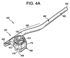
図4A〜4Eは、脊椎コネクター400の別の例示的な実施形態を示す。コネクター400は一般に、第1の脊椎固定エレメント402と、第1の脊椎固定エレメント402を第2の脊椎固定エレメント406に連結するための接続アセンブリ404とを含む。第2の脊椎固定エレメント406は以前に埋め込まれた脊椎固定エレメントであってよく、これに対してコネクター400が連結されていてもよく、又は、コネクター400と共に若しくはコネクター400と同じ手順の一部として埋め込むことができる。接続アセンブリ404は、接続アセンブリ404に対する第1の脊椎固定エレメント402の向きを選択的にロックし、かつ第2の脊椎固定エレメント406に対する接続アセンブリの位置及び向きロックするためのロック機構を含む。図示のように、接続アセンブリ404は、クランプ部材408、ワッシャー410、及びロックエレメント412を含み得る。
4A-4E illustrate another exemplary embodiment of a
図示の実施形態において、第1及び第2の脊椎固定エレメント402、406は細長い脊椎ロッドであるが、代わりに又は追加として、例えば骨プレートなどの、様々な固定エレメントの任意のものを使用できることが理解されよう。第1の脊椎固定エレメント402は、第1の脊椎固定エレメントを接続アセンブリ404に対して回転可能に連結するよう構成された、それ自体に形成されているか又はその第1の末端に連結された、嵌合機構418を含み得る。図示の実施形態において、嵌合機構418は、第1の脊椎固定エレメント402と共に一体形成された環形構造である。嵌合機構418は、それ自体の中を通してクランプ部材408のスタッド部分414を受容するよう構成された中央開口部420を含み得、これによって、嵌合機構は、ロックエレメント412が締められない限り、スタッド部分を中心に(例えば、スタッド部分の長手方向軸を中心に)回転可能である。換言すれば、クランプ部材408は中央開口部420の長手方向軸A1を中心に回転可能であり得る。クランプ部材408は更に、中央開口部420の横断方向軸A2を中心に回転可能であり得る。特に、中央開口部420は、複数の角度でその中にスタッド部分414の位置決めを可能にするよう構成することができる。よって、スタッド部分414は、スタッド部分の長手方向軸が中央開口部の長手方向軸と共線状であるように、又はスタッド部分の長手方向軸が中央開口部の長手方向軸に対して斜めの角度で延在するように、中央開口部420内に配置することができる。そのような位置決めを容易にするために、例えば、中央開口部420は1つ又は2つ以上の方向に細長くてもよく、よって中央開口部は非円形となり得る。更なる例として、中央開口部420は1つ又は2つ以上の横方向の浮き彫り又は切り抜き416を含み得、これにより中央開口部420内でのスタッド部分414の角度付けが可能になる。
In the illustrated embodiment, the first and second
第1の脊椎固定エレメント402の、反対側の第2の末端424は、第1の脊椎固定エレメントの低侵襲性挿入を容易にするよう構成され得る。例えば、第2の末端424は、挿入ポータルから最終的埋込位置への皮下の第1の脊椎固定エレメント402の無外傷的トンネル形成を可能にするよう、丸くなっていても、弾丸状であっても、先細状などであってもよい。
The opposite
第1の脊椎固定エレメント402は、完全に真っ直ぐであってよく、又は1つ若しくは2つ以上の屈曲、湾曲、継手、ずれ、突出などを含み得る。例えば、第1の脊椎固定エレメント402は、患者の解剖学的構造に対し、又は、コネクター400を連結する固定構築物の部分(例えば、骨ねじ422)のためのクリアランスを提供するために、S字形又はZ字形の屈曲を有し得る。図示の実施形態において、第1の脊椎固定エレメント402は、湾曲部分428により別の真っ直ぐな部分430(ここに嵌合機構418が形成されている)に接合された真っ直ぐな部分426を含む。湾曲部分428は、第1の脊椎固定エレメント402が、患者の解剖学的構造の一部分の回り、又はコネクター400が連結される固定構築物の一部分の回りで屈曲できるように、ずれを提供し得る。したがって、ロープロファイルな構築物が形成され、第1の脊椎固定エレメント402の真っ直ぐな部分426は、第2の脊椎固定エレメント406の自然な延長部となる。よって、コネクター400は、第1の脊椎固定エレメント402が骨アンカーを妨げることなしに、第2の脊椎固定エレメントの第1の骨アンカーと第2の骨アンカーとの中間で、以前に設置された第2の脊椎固定エレメント406上にクランプ固定可能であることが理解されよう。第1の脊椎固定エレメント402は剛性であっても、又は屈曲可能であっても、若しくは柔順性であってもよく、又は剛性部分と屈曲可能部分の両方を含んでもよい。よって、いくつかの実施形態において、第1の脊椎固定エレメント402の外形は、手作業で、又は曲げ工具の助けを借りて、具体的な手順の必要に応じて調整することができる。
The first
図4B〜4Cに示すように、嵌合機構418は、クランプ部材408に形成されたショルダー434に係合するよう構成された下表面432と、ワッシャー410に係合するよう構成された上表面436とを含み得る。上表面436は、1つ又は2つ以上の表面特徴を含み得、これはワッシャー410の対応する表面特徴により係合されてよく、これによって、中央開口部の横断方向軸A2を中心とした、クランプ部材408のスタッド部分414と嵌合機構418との間の相対的な角度を、ロックすることができる。図示の実施形態において、表面特徴は、表面に形成された複数の歯を備えた、第1及び第2の円筒形突出部438を含む。歯が図示されているが、ラチェットステップ、粗面化、又はテクスチャー化した接触面などの、任意の様々な表面特徴を使用可能であることが理解されよう。突出部438の歯は、突出部が受容され得るワッシャー410の陥凹部440内に形成された対応する歯と噛み合うことができる。この歯は、スタッド部分414が嵌合機構418の中央開口部420内に配置されているときに、嵌合機構がスタッド部分に対して回転可能な枢動軸A2から、半径方向外向きに延出し得る。他の実施形態において、突出部438はワッシャー410に形成されてよく、陥凹部440は嵌合機構418内に形成され得ることが、理解されよう。
As shown in FIGS. 4B-4C, the
クランプ部材408は、丁番部分444で互いに連結された相対するアーム442を含み得る。一体丁番444が図示されているが、様々な任意の丁番機構を使用できることが理解されよう。例えば、相対するアーム442は、枢動ピンを中心に互いに回転可能に連結され得る。相対するアーム442はそれぞれ、第2の脊椎固定エレメント406を受容するための嵌合部分446を含み得る。相対するアーム442はそれぞれ、更に、丁番部分444と嵌合部分446との間に配置された主部分450を含み得る。相対するアーム442は、ロック解除位置に位置決めすることができ、この位置で、アームの主部分450の間に形成されたスロット452は、実質的に平行な側壁を有し、かつ、クランプ部材408は、アームの嵌合部分446の間に配置された第2の脊椎固定エレメント406に対して可動である。相対するアーム442は更に、ロック位置に位置決めすることができ、この位置で、アームの主部分450は丁番部分444を中心に互いに向かって屈曲され、かつ、アームの嵌合部分446の間に配置された第2の脊椎固定エレメント406はクランプ部材408に対してロックされ、これにより、第2の脊椎固定エレメント406のクランプ部材408に対する回転又は摺動運動に抵抗し又はこれを阻止する。アーム442の外側側壁454は先細であってよく、これによって、ロックエレメント412をクランプ部材408のショルダー434に向かって遠位側に前進させることにより、アームを合わせて圧搾し、これらをロック位置に向かって動かすことができる。アーム442の丁番部分444は弾力性であってよく、これによって、ロックエレメント412をクランプ部材408のショルダー434から近位に後退させることにより、アームが広がり、ロック解除位置に向かって動かすことができる。
嵌合部分446はそれらの間に、クランプ部材408が連結される脊椎固定エレメントに応じた寸法及び/又は形状にされた陥凹部448を画定し得る。例えば、陥凹部448の直径は、第2の脊椎固定エレメント406の直径に実質的に等しくてよい。あるいは、陥凹部448の直径は第2の脊椎固定エレメント406の直径よりわずかに小さくてもよく、これによって、クランプ部材408が第2の脊椎固定エレメント406に「スナップ嵌め」したときに外科医に触覚的フィードバック及び/又は聴覚的フィードバックを提供するスナップ嵌め係合が可能になる。下記で詳しく検討されるように、このフィードバックは特に低侵襲性再置換手術で有利であり得る。別の代替例として、陥凹部448の直径は第2の脊椎固定エレメント406の直径よりわずかに大きくてもよく、ロックエレメント412が締められたときにクランプ動作により引き締められる任意のあそびを備えることができる。つまり、クランプ部材408はよって、様々な寸法又は形状の脊椎固定エレメントに連結するよう構成され得る。いくつかの実施形態において、それぞれ異なる寸法又は形状の陥凹部448を有し得る複数のクランプ部材408が、キットの一部として提供され、これによって具体的な用途に対して適切な寸法及び形状のクランプ部材を選択することが可能になる。
The
図示の陥凹部448は、円筒形の一部分を形成しているが、この陥凹部は、コネクター400が連結される第2の脊椎固定エレメント406の形状に応じて、様々な他の形状を有し得ることが理解されよう。例えば、長方形の断面を有する第2の脊椎固定エレメント406の場合、陥凹部448は対応する長方形形状を有し得る。
The illustrated
陥凹部448は、スタッド部分414の長手方向軸に対して、かつロックエレメント412の長手方向軸に対して、垂直に延在する、長手方向軸A3を有し得る。よって、陥凹部448の長手方向軸A3は、ロックエレメント412が沿って前進する軸に対して垂直であり得る。アーム442の嵌合部分448は、第2の脊椎固定エレメント406の任意の部分の回りに延在するよう構成され得る。図示の実施形態において、アーム442は全体として、第2の脊椎固定エレメント406の周囲の約240度にわたって延在する。他の実施形態において、アームは、第2の脊椎固定エレメント406の周囲の、これより大きい又は小さい範囲を覆うことができる。例えば、被覆範囲は、第2の脊椎固定エレメント406の周囲の約90度〜約270度であり得る。
The
任意の様々なロックエレメントを使用することができるが、図示の実施形態において、ロックエレメントはロックナット412を含む。ロックナット412の少なくとも一部分は、クランプ部材408のスタッド部分414に形成された対応するねじ山にねじで係合するよう構成されたねじ山を含み得る。したがって、スタッド部分414に対する第1の方向のロックナット412の回転は、ロックナットをクランプ部材408のショルダー部分434に向かって押しやり、その間にワッシャー410及び嵌合機構418を圧迫するのに有効であり得、かつ、第2の方向(反対方向)の相対的な回転は、クランプ部材のショルダー部分から離すようにロックナットを動かすのに有効であり得る。
Although any of a variety of locking elements can be used, in the illustrated embodiment, the locking element includes a
コネクター400は、ロック解除構成で位置決め可能であり、この構成では、ロックナット412が締められておらず、嵌合機構418及び第1の脊椎固定エレメント402は、クランプ部材408のスタッド部分414に対して、軸A1及び軸A2を中心に回転可能であり、かつ、クランプ部材は、その嵌合部分446の間に配置された第2の脊椎固定エレメント406に対して回転可能及び摺動可能である。コネクター400は更に、ロックナット412を締めることによって、ロック構成でも位置決め可能であり、これによって、嵌合部分446の間に配置された第2の脊椎固定エレメント406はロックされて、コネクター400に対する第2の脊椎固定エレメントの回転又は摺動に抵抗し又はこれを阻止するよう、更に、嵌合機構418及び第1の脊椎固定エレメント402が、スタッド部分414に対して軸A1及び軸A2を中心に自由に回転可能にはならないようにできる。
The
使用中、脊椎コネクター400は(例えば、下記で詳しく検討するように低侵襲性技法を使用して)手術部位内に位置決めすることができる。以前に設置された第2の脊椎固定エレメント406を、クランプ部材408のアーム442の間に画定される陥凹部448内に位置決めすることができ、更に、クランプ部材を、第2の脊椎固定エレメント406に対して望ましい位置及び/又は向きに動かすことができる。加えて、第1の脊椎固定エレメント402を、軸A1及び軸A2を中心に望ましい位置まで回転させることができる。ロックエレメント412を締めると、アーム442は第2の脊椎固定エレメント406に対してクランプ止めされ、これによって第2の脊椎固定エレメントに対して、クランプ部材408の位置及び向きをロックすることができる。同時に、第1の脊椎固定エレメント402の嵌合機構418は圧搾されて、クランプ部材408のショルダー434及びワッシャー410の歯にしっかりと係合することができ、これにより、スタッド部分414に対する、第1の脊椎固定エレメント402の軸A1又は軸A2を中心とした回転に対して抵抗し又はこれを阻止する。このように、単一のロック機構の動作は、(1)第2の脊椎固定エレメントに対するコネクターの位置及び向きをロックすること、及び(2)第2の脊椎固定エレメントに対する第1の脊椎固定エレメントの第1及び第2の回転自由度をロックすることについて、有効であり得る。第2の脊椎固定エレメントのロックと、コネクターの1つ又は2つ以上の自由度のロックという、この複数の機能性は、単一のロック機構のためのアクセスのみが必要であり、また一工程で2つ以上の機能を実施することが可能になるため、低侵襲性手術において特に有利であり得る。
In use,
脊椎コネクター400は、任意の様々な向きで第2の脊椎固定エレメント406に連結され得る。例えば、脊椎コネクター400は第2の脊椎固定エレメント406に連結することができ、これによってスタッド部分414の長手方向軸は、患者に対して前後方向に延在し得る。更なる例として、脊椎コネクター400は第2の脊椎固定エレメント406に連結することができ、これによってスタッド部分の長手方向軸は患者に対して内外方向に延在し得る。脊椎コネクター400は更に、上記の2つの例の間の任意の向きで、及び第2の脊椎固定エレメントの長さに沿った任意の点で、第2の脊椎固定エレメント406に連結され得る。
The
第1の脊椎固定エレメント406は、第1の脊椎固定エレメントを挿入器具に取り付けるための1つ又は2つ以上の連結機構を含み得る。例えば、第1の脊椎固定エレメント402は、図4Aに示すように、真っ直ぐな部分430の長手方向軸に沿って延在する連結機構456を含み得る。更なる例として、第1の脊椎固定エレメント402は、図4Eに示すように、真っ直ぐな部分430の長手方向軸に対して斜めの角度で延在する連結機構456’を含み得る。図示されていないが、上述の脊椎コネクター100、200、300は同様の連結機構を含み得る。
The first
図5A〜5Dは、脊椎コネクター500の別の例示的な一実施形態を示す。下記に述べる点を除き、脊椎コネクター500の構造及び動作は、上述の脊椎コネクター400の構造及び動作と実質的に同一である。したがって、前記構造及び動作の詳細な説明は、簡潔にするために、ここでは省略する。脊椎コネクター500の嵌合機構518は、脊椎コネクター400に示されるように、横方向に延在するのとは異なり、隣接するロッド部分530に揃って配置される。これにより、コネクター500は、図5Cに示すように、第1の脊椎固定エレメント502の真下に第2の脊椎固定エレメント506が配置されるように位置決めすることができる。コネクター500は更に、図5Dに示すように第2の脊椎固定エレメント506に対して位置決めすることができ、これによって、嵌合機構518の長手方向軸は、第2の脊椎固定エレメントに連結された骨アンカー522の長手方向軸に対して垂直である。
FIGS. 5A-5D illustrate another exemplary embodiment of a
加えて、クランプ部材508の嵌合機構518及びスタッド部分514は、脊椎コネクター400におけるよりも、脊椎コネクター500において、より高い。これは、第1の脊椎固定エレメント502に対して十分なクリアランス空間を提供して、第1の脊椎固定エレメントが骨アンカーを妨げることなしに、骨アンカー522にわたって第2の脊椎固定エレメント506を定位置に保持するよう延在し得る。
In addition, the
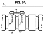
図6A〜6Gは、低侵襲性再置換手術の一環として、隣接する椎骨レベルまで固定構築物を延在させるための、本明細書に開示されるタイプの脊椎コネクターを用いた方法を模式的に図解する。 6A-6G schematically illustrate a method using a spinal connector of the type disclosed herein for extending a fixation construct to an adjacent vertebral level as part of a minimally invasive revision surgery. To do.
図6Aは、患者の脊柱の一部分を示し、第1の脊椎固定エレメント(例えば、細長い固定ロッドR1)はねじS1、S2を用いて、上側の椎骨V1と、隣接する下側の椎骨V2とを連結している。この固定構築物は患者の皮膚Dの下に埋め込まれている。 FIG. 6A shows a portion of the patient's spinal column, where the first spinal fixation element (eg, elongated fixation rod R1) uses screws S1, S2 to connect the upper vertebra V1 and the adjacent lower vertebra V2. It is connected. This fixation construct is implanted under the patient's skin D.
図6Bに示すように、第1の低侵襲性経路P1は、椎骨V2の下にありかつ椎骨V2に隣接する第3椎骨V3にアクセスするよう形成され得る。いくつかの実施形態において、皮下アクセス装置を使用して、この低侵襲性経路P1を提供することができる。 As shown in FIG. 6B, the first minimally invasive pathway P1 may be formed to access a third vertebra V3 below the vertebra V2 and adjacent to the vertebra V2. In some embodiments, a subcutaneous access device can be used to provide this minimally invasive pathway P1.
図6Cに示すように、椎弓根ねじS3は低侵襲性経路P1を介して送達することができ、椎骨V3内に埋め込むことができる。任意の様々な既知の技法を使用して、椎弓根ねじS3を設置することができる。例えば、ねじS3は、所定のねじ軌跡に沿って椎骨V3の椎弓根内にドッキングされたガイドワイヤを伝って送達することができる。ねじS3は、延出する1つ又は2つ以上のロッド整復タブを含み得る。 As shown in FIG. 6C, the pedicle screw S3 can be delivered via the minimally invasive path P1 and can be implanted in the vertebra V3. Any of various known techniques can be used to install the pedicle screw S3. For example, the screw S3 can be delivered along a guide wire docked into the pedicle of the vertebra V3 along a predetermined screw trajectory. The screw S3 may include one or more rod reduction tabs that extend.
図6Dに示すように、第2の低侵襲性経路P2は、椎弓根ねじS1と椎弓根ねじS2との間でロッドR1の一部分にアクセスするよう形成され得る。いくつかの実施形態において、皮下アクセス装置を使用して、この低侵襲性経路P2を提供することができる。 As shown in FIG. 6D, the second minimally invasive pathway P2 may be formed to access a portion of the rod R1 between the pedicle screw S1 and the pedicle screw S2. In some embodiments, a subcutaneous access device can be used to provide this minimally invasive pathway P2.
図6Eに示すように、本明細書に記述されるタイプの脊椎コネクターSCは、脊椎固定エレメントR2を含み、これは第2の低侵襲性経路P2を通過し得る。脊椎コネクターSCを、経路P2を通って前進させることができ、この際、脊椎固定エレメントR2の丸くなった又は弾丸状の先端をロッド整復タブに通して、皮下トンネルにくぐらせ、脊椎固定エレメントR2の一部分を、椎弓根ねじS3のロッド受容陥凹部内に位置決めすることができる。 As shown in FIG. 6E, a spinal connector SC of the type described herein includes a spinal fixation element R2, which can pass through a second minimally invasive pathway P2. The spinal connector SC can be advanced through the path P2, wherein the rounded or bulleted tip of the spinal fixation element R2 is passed through the rod reduction tab and passed through the subcutaneous tunnel, and the spinal fixation element R2 Can be positioned within the rod receiving recess of the pedicle screw S3.
図6Fに示すように、脊椎コネクターSCのクランプ部分又はロッド受容部分は、第1の椎弓根ねじS1と第2の椎弓根ねじS2との間のある位置で、第1の脊椎固定エレメントR1に連結することができる。脊椎コネクターSCの1つ又は2つ以上の自由度を必要に応じて調整することにより、望ましい配列を達成することができる。脊椎コネクターSCは、上述のように、触覚的フィードバック及び/又は聴覚的フィードバックを提供するよう構成することができ(例えば、脊椎固定エレメントR1上への「スナップ嵌め」により)、これにより、コネクターが脊椎固定エレメントR1にしっかり連結されているという確証を外科医に与える。コネクターが望ましい位置になったら、又は任意の他の適切な時点で、止めねじ又はその他のロックエレメントを、第1の低侵襲性経路P1を通して挿入し、脊椎固定エレメントR2を椎弓根ねじS3に固定することができる。止めねじは、事前に椎弓根ねじS3と共に組み立てておくことができ、コネクターと脊椎固定エレメントR2が望ましい位置になった時点で締めることができる。脊椎固定エレメントR2を椎弓根ねじS3に固定する前又は固定した後に、第2の低侵襲性経路P2を通して、ドライバー又はその他の器具を挿入し、脊椎コネクターSCのロックエレメントを締めるか又は他の方法で作動させることができる。上記で詳しく述べたように、単一のロックエレメントと単一の操作運動(例えば、図示のようにロックナットの回転)は、コネクターSCを脊椎固定エレメントR1に対してクランプ止めし、更に、コネクターの残り部分と、延長により脊椎固定エレメントR1とに対して、脊椎固定エレメントR2の任意の自由度をロックするのに有効であり得る。 As shown in FIG. 6F, the clamp portion or rod receiving portion of the spinal connector SC is located at a position between the first pedicle screw S1 and the second pedicle screw S2, and the first spinal fixation element. It can be linked to R1. The desired alignment can be achieved by adjusting one or more degrees of freedom of the spinal connector SC as needed. The spinal connector SC can be configured to provide tactile feedback and / or audible feedback as described above (eg, by a “snap fit” on the spinal fixation element R1) so that the connector The surgeon is assured that it is securely connected to the spinal fixation element R1. Once the connector is in the desired position, or at any other suitable time, a set screw or other locking element is inserted through the first minimally invasive path P1, and the spinal fixation element R2 is inserted into the pedicle screw S3. Can be fixed. The set screw can be pre-assembled with the pedicle screw S3 and tightened when the connector and spinal fixation element R2 are in the desired position. Before or after the spinal fixation element R2 is fixed to the pedicle screw S3, a driver or other instrument is inserted through the second minimally invasive path P2 to tighten the locking element of the spinal connector SC or otherwise. Can be operated in any way. As detailed above, a single locking element and a single operating motion (eg, rotation of the locking nut as shown) clamps the connector SC against the spinal fixation element R1, and further includes a connector. Can be effective to lock any degree of freedom of the spinal fixation element R2 relative to the rest of the spine and the spinal fixation element R1 by extension.
図6Gに示すように、椎弓根ねじS3のロッド整復タブを除去することができ、次いで第1及び第2の低侵襲性経路P1、P2を閉じることができる。脊椎コネクターSCは患者に埋め込んだままにすることができ、これにより、図示のように、以前に設置された構築物を、隣接する椎骨レベルへと延在させることができる。 As shown in FIG. 6G, the rod reduction tab of the pedicle screw S3 can be removed and then the first and second minimally invasive pathways P1, P2 can be closed. The spinal connector SC can be left implanted in the patient, allowing the previously installed construct to extend to the adjacent vertebral level as shown.
本明細書の図面又は説明によって意味された方法工程の任意の順序は、開示方法をその順序で工程を行うことに限定するものと解釈すべきではないことに留意すべきである。そうではなく、本明細書で開示された方法のそれぞれの様々な工程は、任意の様々な順序で行うことができる。更に、説明された方法は、単に例示的な実施形態であって、追加の工程を含む、又はより少ない工程を含む様々な他の方法も、本発明の範囲内である。 It should be noted that any order of method steps implied by the drawings or descriptions herein should not be construed as limiting the disclosed methods to performing the steps in that order. Rather, the various steps of each of the methods disclosed herein can be performed in any of a variety of orders. Further, the described methods are merely exemplary embodiments, and various other methods including additional steps or fewer steps are within the scope of the present invention.
本明細書に開示される脊椎コネクターは、1つ又は2つ以上の態様において上述のものとは異なる任意の様々な方法で使用され得ることが理解されよう。例えば、最初に配置されている構築物は隣接する椎骨に連結している必要はなく、また図示のように2つだけの椎骨レベルに限定する必要もない。更なる例として、既存の構築物は、図示のように下方向ではなく、上方向に延在させることができる。更に別の一例として、既存の構築物は、隣接していない椎骨へ、及び/又は複数の追加椎骨へ、延在させることができる。ヒトの脊椎について手順が示されているが、本明細書のコネクターは、任意の生物若しくは非生物(例えばヒト、動物、機械など)の任意の骨、複数の骨、又はその他の構造に、固定エレメントを連結するのに使用することができる。上記の方法は、必ずしも、以前に埋め込まれた構築物での再置換手術の一環として実施される必要はなく、むしろ、脊椎コネクターを埋め込む同じ手順の一環として埋め込まれた構築物を延在させるのに使用することができる。図には椎弓根ねじ及び固定ロッドが示されているが、骨フック、ワイヤー、テザーなどの様々な他の器具を採用し得ること、及び椎弓根以外の領域に埋め込むことができることが、理解されよう。上述の方法は、低侵襲性手術における使用に限定されず、むしろ、開放手術手順又はハイブリッド手順に使用することができる。 It will be appreciated that the spinal connectors disclosed herein may be used in any of a variety of ways different from those described above in one or more aspects. For example, the initially deployed construct need not be connected to adjacent vertebrae and need not be limited to only two vertebral levels as shown. As a further example, existing constructs can extend upward rather than downward as shown. As yet another example, an existing construct can be extended to non-adjacent vertebrae and / or to a plurality of additional vertebrae. Although the procedure is shown for the human spine, the connector herein can be secured to any bone, multiple bones, or other structures of any living or non-living (eg, human, animal, mechanical, etc.) Can be used to connect elements. The above method need not necessarily be performed as part of a revision surgery with a previously implanted construct, but rather used to extend an implanted construct as part of the same procedure of implanting a spinal connector. can do. Although the figure shows pedicle screws and fixation rods, various other instruments such as bone hooks, wires, tethers, etc. can be employed and can be implanted in areas other than pedicles, It will be understood. The methods described above are not limited to use in minimally invasive surgery, but rather can be used in open surgical procedures or hybrid procedures.
図5Aに示すタイプの脊椎コネクターが、方法説明に示されているが、本明細書に開示される任意の脊椎コネクターに、上述の開示を読んだ当業者には明らかであるような任意の必要な改変を行い、代わりに又は追加として使用することができる。例えば、図2Aに示すコネクター200を、コネクターと椎弓根ねじS3との間に配置されたロッドR2に、コネクター200を連結する前又は連結した後に、低侵襲性経路P2を通して挿入することができる。更なる例として、図1Aに示すコネクター100、図3Aに示すコネクター300、又は図4Aに示すコネクター400を、示されているものと同様の方法で使用することができる。
Although a spinal connector of the type shown in FIG. 5A is shown in the method description, any spinal connector disclosed herein may have any need as will be apparent to those skilled in the art having read the above disclosure. Modifications can be made and used instead or in addition. For example, the
いくつかの実施形態において、ロッドR2を最初に挿入し、それに続いて脊椎コネクターSCを挿入することができる。脊椎コネクターSCの様々なコンポーネントは、患者の体外ですべて組み立てることができ、患者の体内ですべて組み立てることができ、又はそれらの組み合わせであり得る。いくつかの実施形態において、ロッドR2は、示されている方向とは反対の方向に挿入することができる。例えば、ロッドR2は経路P1を通って挿入することができ、その先端を皮下で上方向に前進させ、ロッドR1に隣接する位置にすることができる。脊椎コネクターSCを次に、経路P2に通過させ、ロッドR1、R2を互いに連結させるのに使用することができる。図には屈曲又は湾曲したロッドが示されているが、このロッドは更に、真っ直ぐであってよく、ねじS3の多軸又は単平面状の頭部の枢動に依存して、既存の構築物を回避することができる。いくつかの実施形態において、ロッドR2及び脊椎コネクターSCを最初に埋め込み、その後にねじS3を埋め込むことができる。これは特に、ねじS3が側面から挿入するねじである場合であり得る。脊椎コネクターSCは図示のように、ねじS1、S2の中間でロッドR1に連結することができ、又はねじS1、S2の中間ではないロッドR1の端部に連結することができる。 In some embodiments, the rod R2 can be inserted first, followed by the spinal connector SC. The various components of the spinal connector SC can all be assembled outside the patient's body, can all be assembled inside the patient's body, or a combination thereof. In some embodiments, the rod R2 can be inserted in a direction opposite to the direction shown. For example, rod R2 can be inserted through path P1, and its tip can be advanced subcutaneously upward to a position adjacent to rod R1. The spinal connector SC can then be passed through the path P2 and used to connect the rods R1, R2 to each other. Although the figure shows a bent or curved rod, this rod may also be straight, depending on the pivoting of the multiaxial or uniplanar head of the screw S3 and the existing construction. It can be avoided. In some embodiments, the rod R2 and spinal connector SC can be implanted first, followed by the screw S3. This may in particular be the case when the screw S3 is a screw inserted from the side. The spinal connector SC can be connected to the rod R1 in the middle of the screws S1, S2, as shown, or can be connected to the end of the rod R1, which is not in the middle of the screws S1, S2.
本明細書に開示される脊椎コネクターは、例えば、ニッケル、チタン、ステンレス鋼、ポリマー、セラミック、炭素繊維など、任意の様々な材料で形成することができる。本明細書に開示される脊椎コネクターの1つ又は2つ以上のコンポーネントは、蛍光透視検査及びその他の撮像技法下での可視化を促進するため、放射線不透過性材料で形成することができる。本明細書に開示される装置の他のコンポーネントは、他のコンポーネント又は骨構造の可視化を妨げないようにするため、放射線透過性材料で形成することができる。 The spinal connector disclosed herein can be formed from any of a variety of materials, such as, for example, nickel, titanium, stainless steel, polymer, ceramic, carbon fiber, and the like. One or more components of the spinal connector disclosed herein can be formed of a radiopaque material to facilitate visualization under fluoroscopy and other imaging techniques. Other components of the devices disclosed herein can be formed of a radiolucent material so as not to interfere with visualization of other components or bone structure.
本発明は特定の実施形態を参照して説明されてきたが、説明された発明概念の趣旨及び範囲内で多数の変更がなされてもよいことを理解されたい。したがって、本発明は、説明された実施形態に限定されるものでないことが意図され、むしろ、以下の「特許請求の範囲」の文言によって定義された完全な範囲を有することが意図される。 Although the invention has been described with reference to particular embodiments, it should be understood that numerous modifications can be made within the spirit and scope of the described inventive concept. Accordingly, it is intended that the invention not be limited to the described embodiments, but rather have the full scope defined by the language of the following claims.
〔実施の態様〕
(1) 脊椎コネクターであって、
開口部を画定する嵌合機構を有する第1の脊椎固定エレメントと、
該嵌合機構に連結された接続アセンブリであって、これにより該接続アセンブリの少なくとも一部分が、前記嵌合機構の前記開口部内に受容される、接続アセンブリと、
を含み、該接続アセンブリは、
第2の脊椎固定エレメントを受容するよう構成された陥凹部を画定するクランプと、
該クランプを前記第2の脊椎固定エレメントに対して選択的にロックし、かつ、前記接続アセンブリの1つ又は2つ以上の自由度をロックするよう構成されている、ロックエレメントと、
を含む、脊椎コネクター。
(2) 前記1つ又は2つ以上の自由度は、前記第1の脊椎固定エレメントが前記開口部の長手方向軸を中心に前記クランプに対して回転可能な第1の回転自由度と、前記第1の脊椎固定エレメントが該開口部の横断方向軸を中心に該クランプに対して回転可能な第2の回転自由度と、を含む、実施態様1に記載のコネクター。
(3) 前記クランプが、前記第1の脊椎固定エレメントの前記嵌合機構の前記開口部を通って延在するよう構成された細長いスタッド部分を含み、これにより該スタッド部分は前記開口部の長手方向軸を中心に回転することができ、また前記スタッド部分は前記開口部の横断方向軸を中心に回転することができる、実施態様1に記載のコネクター。
(4) 前記ロックエレメントが、前記クランプのスタッド部分にねじで係合するよう構成されたロックナットを含む、実施態様1に記載のコネクター。
(5) 前記接続アセンブリが、前記ロックナットと前記第1の脊椎固定エレメントの前記嵌合機構との間で、前記クランプの前記スタッド部分の周囲に配置されたワッシャーを更に含む、実施態様4に記載のコネクター。
Embodiment
(1) A spinal connector,
A first spinal fixation element having a mating mechanism defining an opening;
A connection assembly coupled to the mating mechanism, whereby at least a portion of the connection assembly is received within the opening of the mating mechanism;
The connection assembly comprises:
A clamp defining a recess configured to receive a second spinal fixation element;
A locking element configured to selectively lock the clamp relative to the second spinal fixation element and to lock one or more degrees of freedom of the connection assembly;
Including spinal connector.
(2) the one or more degrees of freedom include a first rotational degree of freedom that allows the first spinal fixation element to rotate relative to the clamp about a longitudinal axis of the opening; The connector of
(3) the clamp includes an elongated stud portion configured to extend through the opening of the mating mechanism of the first spinal fixation element, whereby the stud portion is the longitudinal length of the opening; The connector of
The connector of
5. The embodiment of claim 4, wherein the connection assembly further includes a washer disposed about the stud portion of the clamp between the lock nut and the mating mechanism of the first spinal fixation element. The described connector.
(6) 前記ワッシャーは、歯が形成された第1及び第2の陥凹部を含み、前記歯は、前記嵌合機構上に形成された第1及び第2の突出部が少なくとも部分的に前記陥凹部に受容されているときに、前記突出部の上に形成された対応する歯と噛み合うよう構成されている、実施態様5に記載のコネクター。
(7) 前記クランプが、丁番部分で互いに連結される第1及び第2のアームを含み、前記クランプの外側表面は先細であり、これにより、前記ロックエレメントを前記クランプの長手方向軸に沿って前進させると、前記クランプの前記アームを合わせて圧搾するのに有効である、実施態様1に記載のコネクター。
(8) 前記丁番部分が一体丁番を含む、実施態様7に記載のコネクター。
(9) 前記嵌合機構から外向きに延在し、かつ前記第1の脊椎固定エレメントを挿入デバイスに連結するよう構成されている、連結部材を更に含む、実施態様1に記載のコネクター。
(10) 前記クランプは、第2の脊椎固定エレメントが前記陥凹部内に受容されたときに、聴覚的フィードバック及び触覚的フィードバックのうち少なくとも1つを提供するよう構成された、実施態様1に記載のコネクター。
(6) The washer includes first and second recesses in which teeth are formed, and the teeth have at least partially the first and second protrusions formed on the fitting mechanism. Embodiment 6. The connector of embodiment 5, wherein the connector is configured to mate with corresponding teeth formed on the protrusion when received in the recess.
(7) The clamp includes first and second arms connected to each other at a hinge portion, the outer surface of the clamp being tapered, thereby allowing the locking element to follow the longitudinal axis of the clamp. 2. The connector of
(8) The connector according to embodiment 7, wherein the hinge portion includes an integral hinge.
The connector of
10. The embodiment of
(11) 前記第1の脊椎固定エレメントが、第1の細長部分と、該第1の細長部分に平行でありかつ1つ又は2つ以上の次元において該第1の細長部分からずれている第2の細長部分と、該第1の細長部分と該第2の細長部分とを接続する中間部分と、を含む、実施態様1に記載のコネクター。
(12) 前記中間部分は、前記クランプが前記第2の脊椎固定エレメントに取り付けられているときに、前記第2の脊椎固定エレメントに連結された骨アンカーの回りで屈曲するような形状である、実施態様1に記載のコネクター。
(13) 前記嵌合機構が、前記第1の脊椎固定エレメントと一体形成された環形本体を含む、実施態様1に記載のコネクター。
(14) 前記開口部が、それ自体の内側表面内に形成された浮き彫りを含み、これにより前記開口部内での前記クランプの角度付けを容易にする、実施態様1に記載のコネクター。
(15) 前記嵌合機構が、前記第1の脊椎固定エレメントの端部から長手方向に延在する、実施態様1に記載のコネクター。
(11) wherein the first spinal fixation element includes a first elongated portion, a first parallel to the first elongated portion, and offset from the first elongated portion in one or more dimensions. The connector of
(12) The intermediate portion is shaped to bend around a bone anchor coupled to the second spinal fixation element when the clamp is attached to the second spinal fixation element. The connector according to
(13) The connector according to
14. The connector of
(15) The connector of
(16) 前記嵌合機構が、前記第1の脊椎固定エレメントの端部から横断方向に延在する、実施態様1に記載のコネクター。
(17) 前記接続アセンブリは、第1及び第2のシューが摺動可能に配置されたハウジングを含み、前記ロックエレメントは、前記第1のシューを押して前記嵌合機構に係合させることにより前記ハウジングに対する前記第1の脊椎固定エレメントの向きをロックし、かつ、前記第2のシューを押して前記第2の脊椎固定エレメントに係合させることにより前記クランプ内に前記第2の脊椎固定エレメントをロックするよう構成されている、実施態様1に記載のコネクター。
(18) 前記クランプが、間に配置された付勢エレメントを備えた上側クランプアーム及び下側クランプアームを含み、前記ロックエレメントは、該上側クランプアーム、該付勢エレメント、及び該下側クランプアームの中に形成された開口部を通って延在する、実施態様1に記載のコネクター。
(19) 前記1つ又は2つ以上の自由度には、前記第1の脊椎固定エレメントが前記ロックエレメントの長手方向軸を中心として前記上側及び前記下側クランプアームに対して回転可能な、回転自由度を含む、実施態様18に記載のコネクター。
(20) 脊椎コネクターであって、
脊椎固定エレメントを把持するよう構成された第1及び第2のアームを有するクランプであって、該第1及び第2のアームの少なくとも一部分がスタッド部分を画定する、クランプと、
該クランプの前記スタッド部分が通って延在する開口部を画定する嵌合機構を有する、脊椎固定エレメントと、
前記スタッド部分と係合することにより、前記第1及び第2のアームを互いに向かって選択的に動かし、かつ、前記スタッド部分の、前記開口部の長手方向軸を中心とした回転、及び前記開口部の横断方向軸を中心とした回転をロックするように構成された、ロックエレメントと、
を含む、脊椎コネクター。
16. The connector according to
(17) The connection assembly includes a housing in which first and second shoes are slidably arranged, and the locking element is configured to push the first shoe into engagement with the fitting mechanism. Locking the orientation of the first spinal fixation element relative to the housing and locking the second spinal fixation element within the clamp by pushing the second shoe into engagement with the second spinal fixation element The connector of
(18) The clamp includes an upper clamp arm and a lower clamp arm having a biasing element disposed therebetween, and the lock element includes the upper clamp arm, the biasing element, and the lower clamp arm. The connector of
(19) For the one or more degrees of freedom, the first spinal fixation element is rotatable relative to the upper and lower clamp arms about the longitudinal axis of the locking element Embodiment 19. The connector according to embodiment 18, comprising degrees of freedom.
(20) a spinal connector,
A clamp having first and second arms configured to grip a spinal fixation element, wherein at least a portion of the first and second arms define a stud portion;
A spinal fixation element having a mating mechanism defining an opening through which the stud portion of the clamp extends;
Engagement with the stud portion selectively moves the first and second arms toward each other, and rotation of the stud portion about the longitudinal axis of the opening, and the opening A locking element configured to lock rotation about the transverse axis of the part;
Including spinal connector.
(21) 前記ロックエレメントが、前記クランプの前記スタッド部分にねじで係合するよう構成されたロックナットを含む、実施態様20に記載のコネクター。
(22) 前記ロックナットと前記脊椎固定エレメントの前記嵌合機構との間で、前記クランプの前記スタッド部分の周囲に配置されたワッシャーを更に含む、実施態様21に記載のコネクター。
(23) 前記ワッシャーは、表面特徴が形成された第1及び第2の陥凹部を含み、前記表面特徴は、前記嵌合機構上に形成された第1及び第2の突出部が少なくとも部分的に前記陥凹部に受容されているときに、前記第1及び第2の突出部の上に形成された対応する表面特徴と噛み合うよう構成されている、実施態様22に記載のコネクター。
(24) 前記第1及び第2のアームが丁番部分で互いに連結され、かつ前記クランプの外側表面は先細であり、これにより、前記ロックエレメントを前記クランプの長手方向軸に沿って前進させると、前記クランプの前記アームを合わせて圧搾するのに有効である、実施態様20に記載のコネクター。
(25) 脊椎コネクターであって、
第2の部分に対して平行でかつずれている第1の部分を有する第1の細長ロッドであって、前記第1及び第2の部分は移行部分で接合されている、第1の細長ロッドと、
該ロッドの前記第1の部分から延在している環形嵌合機構と、
第2の細長ロッドを受容することができる陥凹部を間に画定する第1及び第2のクランプアームを有するクランプであって、該クランプは、前記環形嵌合機構の中央開口部を通って延在するスタッド部分を有し、これにより前記嵌合機構は前記スタッド部分のショルダーに対して押し付けられ、かつ前記スタッド部分は前記中央開口部の長手方向軸及び前記中央開口部の横断方向軸を中心に回転可能である、クランプと、
前記スタッド部分を覆って配置されるワッシャーと、
前記スタッド部分にねじで係合するロックナットであって、これにより前記ワッシャーが前記ロックナットと前記嵌合機構との間に配置され、かつ前記嵌合機構が前記ワッシャーと前記ショルダーとの間に配置される、ロックナットと、
を含み、
該ロックナットを締めることは、前記中央開口部の前記長手方向軸及び前記横断方向軸を中心とした前記スタッド部分の回転をロックし、かつ、前記第1及び第2のクランプアームを合わせて圧搾することで、前記陥凹部内に配置された第2の細長ロッドに前記クランプをロックするのに、有効である、脊椎コネクター。
21. The connector of embodiment 20, wherein the locking element includes a lock nut configured to threadably engage the stud portion of the clamp.
The connector of claim 21, further comprising a washer disposed about the stud portion of the clamp between the lock nut and the mating mechanism of the spinal fixation element.
(23) The washer includes first and second recesses in which surface features are formed, and the surface features include at least partial first and second protrusions formed on the fitting mechanism. 23. The connector of embodiment 22, wherein the connector is configured to mate with corresponding surface features formed on the first and second protrusions when received in the recess.
(24) The first and second arms are connected to each other at a hinge portion, and the outer surface of the clamp is tapered so that when the locking element is advanced along the longitudinal axis of the clamp Embodiment 21. The connector of embodiment 20, effective to squeeze together the arms of the clamp.
(25) A spinal connector,
A first elongate rod having a first portion parallel to and offset from the second portion, wherein the first and second portions are joined at a transition portion. When,
An annular fitting mechanism extending from the first portion of the rod;
A clamp having first and second clamp arms defining a recess therebetween for receiving a second elongate rod, the clamp extending through a central opening of the annular mating mechanism. The stud portion is located against the shoulder of the stud portion, and the stud portion is centered on a longitudinal axis of the central opening and a transverse axis of the central opening. A clamp that is rotatable,
A washer disposed over the stud portion;
A lock nut that engages with the stud portion with a screw, whereby the washer is disposed between the lock nut and the fitting mechanism, and the fitting mechanism is disposed between the washer and the shoulder. Arranged with a lock nut,
Including
Tightening the lock nut locks rotation of the stud portion about the longitudinal axis and the transverse axis of the central opening and squeezes the first and second clamp arms together Thus, a spinal connector that is effective to lock the clamp to a second elongate rod disposed in the recess.
(26) 前記ワッシャー及び前記嵌合機構の一方が、中に複数の歯が形成された湾曲した陥凹部を含み、前記複数の歯は、前記ワッシャー及び前記嵌合機構の他方の上に形成された湾曲した突出部が少なくとも部分的に前記陥凹部に受容されたときに、前記突出部の上に形成された複数の歯と係合するよう構成されている、実施態様25に記載の脊椎コネクター。
(27) 脊椎コネクターであって、
第1の脊椎固定エレメントを受容するよう構成された陥凹部を画定する第1のクランプ部材と、
第2の脊椎固定エレメントを受容するよう構成された陥凹部を画定する第2のクランプ部材と、
該第1及び第2のクランプ部材内に形成された開口部を通って延在するロックエレメントであって、該ロックエレメントは、前記第1のクランプ部材を前記第1の脊椎固定ロッドに選択的にロックし、前記第2のクランプ部材を前記第2の脊椎固定ロッドにロックし、かつ前記第1のクランプ部材と第2のクランプ部材との間の1つ又は2つ以上の自由度をロックするよう構成されている、ロックエレメントと、
を含む、脊椎コネクター。
(28) 前記1つ又は2つ以上の自由度は、前記第1のクランプ部材が前記ロックエレメントの長手方向軸を中心に前記第2のクランプ部材に対して回転可能な回転自由度と、前記第1のクランプ部材が前記ロックエレメントの長手方向軸に対して垂直に延在する軸に沿って前記第2のクランプ部材に対して並進可能な並進自由度とを含む、実施態様27に記載のコネクター。
(29) 前記第2のクランプ部材は、前記ロックエレメントがロック解除構成であるときに、前記ロックエレメントの長手方向軸を中心に前記第1のクランプ部材に対して回転可能である、実施態様27に記載のコネクター。
(30) 前記第2のクランプ部材は、前記ロックエレメントがロック解除構成であるときに、前記ロックエレメントの長手方向軸に対して垂直に延在する軸に沿って前記第1のクランプ部材に対して並進可能である、実施態様27に記載のコネクター。
(26) One of the washer and the fitting mechanism includes a curved recess having a plurality of teeth formed therein, and the plurality of teeth are formed on the other of the washer and the fitting mechanism. 26. The spinal connector of embodiment 25, wherein the spinal connector is configured to engage a plurality of teeth formed on the protrusion when the curved curved protrusion is at least partially received in the recess. .
(27) a spinal connector,
A first clamping member defining a recess configured to receive a first spinal fixation element;
A second clamping member defining a recess configured to receive a second spinal fixation element;
A locking element extending through openings formed in the first and second clamping members, wherein the locking element selectively selects the first clamping member for the first spinal fixation rod. Locking the second clamping member to the second spinal fixation rod and locking one or more degrees of freedom between the first clamping member and the second clamping member. A locking element configured to:
Including spinal connector.
(28) The one or more degrees of freedom include a rotational degree of freedom in which the first clamp member is rotatable with respect to the second clamp member around a longitudinal axis of the lock element, and 28. The embodiment of claim 27, wherein the first clamping member includes a translational degree of freedom that is translatable relative to the second clamping member along an axis extending perpendicular to a longitudinal axis of the locking element. connector.
(29) Embodiment 27 wherein the second clamp member is rotatable relative to the first clamp member about a longitudinal axis of the lock element when the lock element is in an unlocked configuration. Connector described in 1.
(30) The second clamp member may be disposed on the first clamp member along an axis extending perpendicular to a longitudinal axis of the lock element when the lock element is in an unlocked configuration. 28. The connector of embodiment 27, wherein the connector is translatable.
(31) 脊椎固定方法であって、
第1の椎骨にアクセスする第1の低侵襲性経路を形成することと、
該第1の低侵襲性経路を通してねじを送達することと、
前記第1の椎骨に前記ねじを埋め込むことと、
少なくとも1つの他の椎骨に連結された第1の脊椎固定エレメントにアクセスする第2の低侵襲性経路を形成することと、
第2の脊椎固定エレメント、及びそれに連結された脊椎コネクターを、前記第2の低侵襲性経路を通して送達することと、
1つ又は2つ以上の自由度で、前記第2の脊椎固定エレメントに対して前記脊椎コネクターを動かすことにより、前記ねじで係合されている前記第2の脊椎固定エレメントの少なくとも一部分を位置決めすることと、
前記脊椎コネクターのロックエレメントを作動させることにより、前記脊椎コネクターを前記第1の脊椎固定エレメントにロックし、かつ前記1つ又は2つ以上の自由度をロックすることと、
を含む、脊椎固定方法。
(32) 前記脊椎コネクターを動かすことが、前記第2の脊椎固定エレメントを皮下で動かして前記ねじに係合させることを含む、実施態様31に記載の方法。
(33) 前記第1の脊椎固定エレメントが、以前に埋め込まれた脊椎固定エレメントである、実施態様31に記載の方法。
(34) 前記脊椎コネクターが、前記第2の脊椎固定エレメントの嵌合機構の開口部を通って延在するスタッド部分を有するクランプを含み、更に、前記1つ又は2つ以上の自由度は、前記第2の脊椎固定エレメントが前記開口部の長手方向軸を中心に前記クランプに対して回転可能な第1の回転自由度と、前記第2の脊椎固定エレメントが前記開口部の横断方向軸を中心に前記クランプに対して回転可能な第2の回転自由度と、を含む、実施態様31に記載の方法。
(35) 前記脊椎コネクターが、前記第2の脊椎固定エレメントの嵌合機構の開口部を通って延在するスタッド部分を有するクランプを含み、更に、前記脊椎コネクターを動かすことは、前記中央開口部の長手方向軸を中心に、及び前記中央開口部の横断方向軸を中心に、前記スタッド部分を枢動させることを含む、実施態様31に記載の方法。
(31) A spinal fixation method,
Forming a first minimally invasive pathway to access the first vertebra;
Delivering a screw through the first minimally invasive route;
Embedding the screw in the first vertebra;
Forming a second minimally invasive pathway to access a first spinal fixation element coupled to at least one other vertebra;
Delivering a second spinal fixation element and a spinal connector coupled thereto through the second minimally invasive route;
Positioning at least a portion of the second spinal fixation element engaged with the screw by moving the spinal connector relative to the second spinal fixation element in one or more degrees of freedom. And
Activating the locking element of the spinal connector to lock the spinal connector to the first spinal fixation element and to lock the one or more degrees of freedom;
A spinal fixation method comprising:
32. The method of embodiment 31, wherein moving the spinal connector comprises moving the second spinal fixation element subcutaneously to engage the screw.
33. The method of embodiment 31, wherein the first spinal fixation element is a previously implanted spinal fixation element.
(34) The spinal connector includes a clamp having a stud portion that extends through an opening of the mating mechanism of the second spinal fixation element, and the one or more degrees of freedom include: A first degree of freedom of rotation that allows the second spinal fixation element to rotate relative to the clamp about a longitudinal axis of the opening; and a second spinal fixation element that defines a transverse axis of the opening. 32. The method of embodiment 31, comprising a second rotational degree of freedom rotatable about the clamp at a center.
35. The spine connector includes a clamp having a stud portion extending through an opening of the mating mechanism of the second spinal fixation element, and moving the spine connector further comprises the central opening. 32. The method of embodiment 31, comprising pivoting the stud portion about a longitudinal axis of the central aperture and about a transverse axis of the central opening.
(36) 前記脊椎コネクターが、前記第2の脊椎固定エレメントの嵌合機構の開口部を通って延在するスタッド部分を有するクランプを含み、更に、前記ロックエレメントを作動させることは、前記スタッド部分にねじで係合されているロックナットを締めることにより、前記スタッド部分のショルダーに対して前記嵌合機構を圧迫することを含む、実施態様31に記載の方法。
(37) 前記脊椎コネクターが、前記第2の脊椎固定エレメントの嵌合機構の開口部を通って延在するスタッド部分と、前記スタッド部分の周囲に配置されたワッシャーと、を有するクランプを含み、更に、前記脊椎コネクターを動かすことは、前記ワッシャー上に形成された表面特徴を、前記嵌合機構上に形成された対応する表面特徴に係合させることを含む、実施態様31に記載の方法。
(38) 前記脊椎コネクターが、丁番部分で互いに連結されかつ先細の外側表面を有する第1及び第2のアームを含み、更に、前記ロックエレメントを作動させることは、前記第1及び第2のアームに沿ってロックナットを前進させることにより前記アームを合わせて圧搾することを含む、実施態様31に記載の方法。
(39) 前記ロックエレメントを作動させることが、単一のロックエレメントを回転させることのみからなる、実施態様31に記載の方法。
(40) 前記第2の脊椎固定エレメントが、前記第1の脊椎固定エレメントに固定された骨アンカーの周囲に延在するように、前記第2の脊椎固定エレメントを位置決めすることを更に含む、実施態様31に記載の方法。
(36) The spinal connector includes a clamp having a stud portion extending through an opening of the mating mechanism of the second spinal fixation element, and further activating the locking element comprises the stud portion. 32. The method of embodiment 31, comprising compressing the mating mechanism against a shoulder of the stud portion by tightening a lock nut that is threadedly engaged with the stud.
(37) The spine connector includes a clamp having a stud portion extending through an opening of the fitting mechanism of the second spinal fixation element, and a washer disposed around the stud portion; 32. The method of embodiment 31, wherein moving the spinal connector further includes engaging surface features formed on the washer with corresponding surface features formed on the mating mechanism.
(38) The spinal connector includes first and second arms connected to each other at a hinge portion and having a tapered outer surface; and further, actuating the locking element comprises the first and second 32. The method of embodiment 31, comprising squeezing the arms together by advancing a lock nut along the arms.
39. The method of embodiment 31, wherein actuating the locking element consists only of rotating a single locking element.
(40) The method further comprising positioning the second spinal fixation element such that the second spinal fixation element extends around a bone anchor secured to the first spinal fixation element. 32. A method according to embodiment 31.
(41) 前記第1の脊椎固定エレメントを骨に固定している第1の骨アンカーと第2の骨アンカーとの間の位置で、前記脊椎コネクターを前記第1の脊椎固定エレメントに取り付けることを更に含む、実施態様31に記載の方法。
(42) 脊椎固定方法であって、
第1の椎骨にアクセスする第1の低侵襲性経路を形成することと、
該第1の低侵襲性経路を通してねじを送達することと、
前記第1の椎骨に前記ねじを埋め込むことと、
少なくとも1つの他の椎骨に連結された第1の脊椎固定エレメントにアクセスする第2の低侵襲性経路を形成することと、
前記第1の低侵襲性経路を通して第2の脊椎固定エレメントを送達することにより、前記第2の低侵襲性経路内で前記第2の脊椎固定エレメントの一部分を位置決めすることと、
前記第2の低侵襲性経路を通して脊椎コネクターを挿入し、該脊椎コネクターを前記第1及び第2の脊椎固定エレメントに連結することと、
該第2の脊椎固定エレメントを前記ねじに固定することと、
を含む、脊椎固定方法。
(43) 前記脊椎コネクターを連結することが、
該脊椎コネクターの1つ又は2つ以上の自由度を調整することにより、前記第1及び第2の脊椎固定エレメントに対して前記脊椎コネクターを位置決めすることと、
前記脊椎コネクターのロックエレメントを作動させることにより、前記脊椎コネクターを前記第1及び第2の脊椎固定エレメントにロックし、かつ前記1つ又は2つ以上の自由度をロックすることと、
を含む、実施態様42に記載の方法。
(44) 脊椎固定方法であって、
第1の脊椎固定エレメントが連結された脊椎コネクターを、第2の脊椎固定エレメントにクランプ止めすることと、
前記脊椎コネクターのロック機構を作動させることにより、前記脊椎コネクターの前記第2の脊椎固定エレメントへのロックと、前記脊椎コネクターと前記第1の脊椎固定エレメントとの間の1つ又は2つ以上の自由度のロックと、を同時に行うことと、
を含む、脊椎固定方法。
(41) attaching the spinal connector to the first spinal fixation element at a position between the first bone anchor and the second bone anchor fixing the first spinal fixation element to the bone; 32. The method of embodiment 31, further comprising:
(42) A spinal fixation method,
Forming a first minimally invasive pathway to access the first vertebra;
Delivering a screw through the first minimally invasive route;
Embedding the screw in the first vertebra;
Forming a second minimally invasive pathway to access a first spinal fixation element coupled to at least one other vertebra;
Positioning a portion of the second spinal fixation element within the second minimally invasive pathway by delivering a second spinal fusion element through the first minimally invasive pathway;
Inserting a spinal connector through the second minimally invasive pathway and coupling the spinal connector to the first and second spinal fixation elements;
Securing the second spinal fixation element to the screw;
A spinal fixation method comprising:
(43) connecting the spinal connector;
Positioning the spinal connector relative to the first and second spinal fixation elements by adjusting one or more degrees of freedom of the spinal connector;
Activating the locking element of the spinal connector to lock the spinal connector to the first and second spinal fixation elements and to lock the one or more degrees of freedom;
43. The method of embodiment 42, comprising:
(44) A spinal fixation method,
Clamping the spinal connector to which the first spinal fixation element is coupled to the second spinal fixation element;
Activating the locking mechanism of the spinal connector to lock the spinal connector to the second spinal fixation element and one or more between the spinal connector and the first spinal fixation element Simultaneously performing a degree of freedom locking,
A spinal fixation method comprising:
Claims (30)
開口部を画定する嵌合機構を有する第1の脊椎固定エレメントと、
該嵌合機構に連結された接続アセンブリであって、これにより該接続アセンブリの少なくとも一部分が、前記嵌合機構の前記開口部内に受容される、接続アセンブリと、
を含み、該接続アセンブリは、
第2の脊椎固定エレメントを受容するよう構成された陥凹部を画定するクランプと、
該クランプを前記第2の脊椎固定エレメントに対して選択的にロックし、かつ、前記接続アセンブリの1つ又は2つ以上の自由度をロックするよう構成されている、ロックエレメントと、
を含む、脊椎コネクター。 A spinal connector,
A first spinal fixation element having a mating mechanism defining an opening;
A connection assembly coupled to the mating mechanism, whereby at least a portion of the connection assembly is received within the opening of the mating mechanism;
The connection assembly comprises:
A clamp defining a recess configured to receive a second spinal fixation element;
A locking element configured to selectively lock the clamp relative to the second spinal fixation element and to lock one or more degrees of freedom of the connection assembly;
Including spinal connector.
脊椎固定エレメントを把持するよう構成された第1及び第2のアームを有するクランプであって、該第1及び第2のアームの少なくとも一部分がスタッド部分を画定する、クランプと、
該クランプの前記スタッド部分が通って延在する開口部を画定する嵌合機構を有する、脊椎固定エレメントと、
前記スタッド部分と係合することにより、前記第1及び第2のアームを互いに向かって選択的に動かし、かつ、前記スタッド部分の、前記開口部の長手方向軸を中心とした回転、及び前記開口部の横断方向軸を中心とした回転をロックするように構成された、ロックエレメントと、
を含む、脊椎コネクター。 A spinal connector,
A clamp having first and second arms configured to grip a spinal fixation element, wherein at least a portion of the first and second arms define a stud portion;
A spinal fixation element having a mating mechanism defining an opening through which the stud portion of the clamp extends;
Engagement with the stud portion selectively moves the first and second arms toward each other, and rotation of the stud portion about the longitudinal axis of the opening, and the opening A locking element configured to lock rotation about the transverse axis of the part;
Including spinal connector.
第2の部分に対して平行でかつずれている第1の部分を有する第1の細長ロッドであって、前記第1及び第2の部分は移行部分で接合されている、第1の細長ロッドと、
該ロッドの前記第1の部分から延在している環形嵌合機構と、
第2の細長ロッドを受容することができる陥凹部を間に画定する第1及び第2のクランプアームを有するクランプであって、該クランプは、前記環形嵌合機構の中央開口部を通って延在するスタッド部分を有し、これにより前記嵌合機構は前記スタッド部分のショルダーに対して押し付けられ、かつ前記スタッド部分は前記中央開口部の長手方向軸及び前記中央開口部の横断方向軸を中心に回転可能である、クランプと、
前記スタッド部分を覆って配置されるワッシャーと、
前記スタッド部分にねじで係合するロックナットであって、これにより前記ワッシャーが前記ロックナットと前記嵌合機構との間に配置され、かつ前記嵌合機構が前記ワッシャーと前記ショルダーとの間に配置される、ロックナットと、
を含み、
該ロックナットを締めることは、前記中央開口部の前記長手方向軸及び前記横断方向軸を中心とした前記スタッド部分の回転をロックし、かつ、前記第1及び第2のクランプアームを合わせて圧搾することで、前記陥凹部内に配置された第2の細長ロッドに前記クランプをロックするのに、有効である、脊椎コネクター。 A spinal connector,
A first elongate rod having a first portion parallel to and offset from the second portion, wherein the first and second portions are joined at a transition portion. When,
An annular fitting mechanism extending from the first portion of the rod;
A clamp having first and second clamp arms defining a recess therebetween for receiving a second elongate rod, the clamp extending through a central opening of the annular mating mechanism. The stud portion is located against the shoulder of the stud portion, and the stud portion is centered on a longitudinal axis of the central opening and a transverse axis of the central opening. A clamp that is rotatable,
A washer disposed over the stud portion;
A lock nut that engages with the stud portion with a screw, whereby the washer is disposed between the lock nut and the fitting mechanism, and the fitting mechanism is disposed between the washer and the shoulder. Arranged with a lock nut,
Including
Tightening the lock nut locks rotation of the stud portion about the longitudinal axis and the transverse axis of the central opening and squeezes the first and second clamp arms together Thus, a spinal connector that is effective to lock the clamp to a second elongate rod disposed in the recess.
第1の脊椎固定エレメントを受容するよう構成された陥凹部を画定する第1のクランプ部材と、
第2の脊椎固定エレメントを受容するよう構成された陥凹部を画定する第2のクランプ部材と、
該第1及び第2のクランプ部材内に形成された開口部を通って延在するロックエレメントであって、該ロックエレメントは、前記第1のクランプ部材を前記第1の脊椎固定ロッドに選択的にロックし、前記第2のクランプ部材を前記第2の脊椎固定ロッドにロックし、かつ前記第1のクランプ部材と第2のクランプ部材との間の1つ又は2つ以上の自由度をロックするよう構成されている、ロックエレメントと、
を含む、脊椎コネクター。 A spinal connector,
A first clamping member defining a recess configured to receive a first spinal fixation element;
A second clamping member defining a recess configured to receive a second spinal fixation element;
A locking element extending through openings formed in the first and second clamping members, wherein the locking element selectively selects the first clamping member for the first spinal fixation rod. Locking the second clamping member to the second spinal fixation rod and locking one or more degrees of freedom between the first clamping member and the second clamping member. A locking element configured to:
Including spinal connector.
Applications Claiming Priority (3)
| Application Number | Priority Date | Filing Date | Title |
|---|---|---|---|
| US14/496,804 | 2014-09-25 | ||
| US14/496,804 US9724131B2 (en) | 2014-09-25 | 2014-09-25 | Spinal connectors and related methods |
| PCT/US2015/051172 WO2016048871A1 (en) | 2014-09-25 | 2015-09-21 | Spinal connectors and related methods |
Publications (2)
| Publication Number | Publication Date |
|---|---|
| JP2017529183A true JP2017529183A (en) | 2017-10-05 |
| JP6692802B2 JP6692802B2 (en) | 2020-05-13 |
Family
ID=54249634
Family Applications (1)
| Application Number | Title | Priority Date | Filing Date |
|---|---|---|---|
| JP2017516476A Active JP6692802B2 (en) | 2014-09-25 | 2015-09-21 | Spinal connector and related methods |
Country Status (5)
| Country | Link |
|---|---|
| US (4) | US9724131B2 (en) |
| EP (1) | EP3197380B1 (en) |
| JP (1) | JP6692802B2 (en) |
| AU (1) | AU2015321664B2 (en) |
| WO (1) | WO2016048871A1 (en) |
Families Citing this family (19)
| Publication number | Priority date | Publication date | Assignee | Title |
|---|---|---|---|---|
| US9247964B1 (en) * | 2011-03-01 | 2016-02-02 | Nuasive, Inc. | Spinal Cross-connector |
| US9724131B2 (en) | 2014-09-25 | 2017-08-08 | DePuy Synthes Products, Inc. | Spinal connectors and related methods |
| US10383663B2 (en) * | 2016-03-29 | 2019-08-20 | Globus Medical, Inc. | Revision connectors, systems and methods thereof |
| US20170325849A1 (en) * | 2016-05-13 | 2017-11-16 | Spineology Inc. | Multiple diameter spinal rod clamping mechanism |
| US10517647B2 (en) | 2016-05-18 | 2019-12-31 | Medos International Sarl | Implant connectors and related methods |
| US10321939B2 (en) | 2016-05-18 | 2019-06-18 | Medos International Sarl | Implant connectors and related methods |
| US10413330B2 (en) | 2016-08-09 | 2019-09-17 | Warsaw Orthopedic, Inc. | Spinal implant system and method |
| US10398476B2 (en) | 2016-12-13 | 2019-09-03 | Medos International Sàrl | Implant adapters and related methods |
| US10492835B2 (en) | 2016-12-19 | 2019-12-03 | Medos International Sàrl | Offset rods, offset rod connectors, and related methods |
| US10238432B2 (en) | 2017-02-10 | 2019-03-26 | Medos International Sàrl | Tandem rod connectors and related methods |
| US10172653B2 (en) * | 2017-03-09 | 2019-01-08 | Alphatec Spine, Inc. | Osteotomy instrument |
| US10966761B2 (en) | 2017-03-28 | 2021-04-06 | Medos International Sarl | Articulating implant connectors and related methods |
| US10561454B2 (en) | 2017-03-28 | 2020-02-18 | Medos International Sarl | Articulating implant connectors and related methods |
| US10258386B2 (en) * | 2017-06-15 | 2019-04-16 | Warsaw Orthopedic, Inc. | Spinal construct and method |
| US11076890B2 (en) | 2017-12-01 | 2021-08-03 | Medos International Sàrl | Rod-to-rod connectors having robust rod closure mechanisms and related methods |
| USD956543S1 (en) * | 2020-09-30 | 2022-07-05 | Wenjie Li | Locking connector |
| US11376046B1 (en) | 2021-02-01 | 2022-07-05 | Warsaw Orthopedic, Inc. | Spinal implant system and method |
| WO2023023340A2 (en) * | 2021-08-20 | 2023-02-23 | Snj Patents, Llc | Minimally invasive surgery add on screw system |
| US11331125B1 (en) | 2021-10-07 | 2022-05-17 | Ortho Inventions, Llc | Low profile rod-to-rod coupler |
Citations (7)
| Publication number | Priority date | Publication date | Assignee | Title |
|---|---|---|---|---|
| JP2005516723A (en) * | 2002-02-11 | 2005-06-09 | シアンティクス | Connection system between spine rod and crossbar |
| US20090105765A1 (en) * | 2007-10-23 | 2009-04-23 | Intrepid Orthopedics, Llc | Spinal rod cross connector |
| JP2009532182A (en) * | 2006-04-05 | 2009-09-10 | ウォーソー・オーソペディック・インコーポレーテッド | Horizontal connector assembly |
| US8246657B1 (en) * | 2009-06-29 | 2012-08-21 | Nuvasive, Inc. | Spinal cross connector |
| WO2013085958A1 (en) * | 2011-12-08 | 2013-06-13 | Spine Wave, Inc. | Apparatus and devices for percutaneously extending an existing spinal construct |
| US20140052189A1 (en) * | 2012-08-15 | 2014-02-20 | Blackstone Medical, Inc. | Pivoting spinal fixation devices |
| US8758411B1 (en) * | 2011-10-25 | 2014-06-24 | Nuvasive, Inc. | Implants and methods for treating spinal disorders |
Family Cites Families (32)
| Publication number | Priority date | Publication date | Assignee | Title |
|---|---|---|---|---|
| US5645544A (en) | 1995-09-13 | 1997-07-08 | Danek Medical, Inc. | Variable angle extension rod |
| US6551318B1 (en) * | 2000-07-26 | 2003-04-22 | Stahurski Consulting Inc. | Spinal column retaining apparatus |
| US8021399B2 (en) * | 2005-07-19 | 2011-09-20 | Stephen Ritland | Rod extension for extending fusion construct |
| AU2002368445B2 (en) * | 2002-12-06 | 2006-10-05 | Synthes Gmbh | Device for stabilising bones |
| US20040210216A1 (en) * | 2003-04-17 | 2004-10-21 | Farris Robert A | Spinal fixation system and method |
| US8236028B2 (en) * | 2004-03-31 | 2012-08-07 | Depuy Spine Sarl | Spinal rod connector |
| US7717938B2 (en) | 2004-08-27 | 2010-05-18 | Depuy Spine, Inc. | Dual rod cross connectors and inserter tools |
| DE502005005095D1 (en) | 2005-02-09 | 2008-10-02 | Stryker Trauma Sa | Insert for a clamping element, clamping element with such an insert and articulated connection formed therefrom |
| WO2009049206A2 (en) * | 2005-07-22 | 2009-04-16 | Vertiflex, Inc. | Offset connector for a spinal stabilization rod |
| ES2246744B1 (en) * | 2005-10-11 | 2006-12-01 | Implantvet, S.L. | ARTICULATION FOR MUTUAL SOLIDARIZATION BETWEEN BARS AND / OR NEEDLES IN AN EXTERNAL FIXING DEVICE FOR THE REDUCTION OF OSE FRACTURES. |
| US20070270817A1 (en) * | 2006-04-24 | 2007-11-22 | Sdgi Holdings, Inc. | Connector apparatus |
| WO2008027940A1 (en) | 2006-08-31 | 2008-03-06 | Warsaw Orthopedic, Inc | Spinal rod extenders and methods of use |
| US7922746B2 (en) * | 2006-08-31 | 2011-04-12 | Warsaw Orthopedic, Inc. | Spinal rod extenders and methods of use |
| US7648521B2 (en) * | 2007-03-15 | 2010-01-19 | Zimmer Spine, Inc. | System and method for minimally invasive spinal surgery |
| US9277940B2 (en) * | 2008-02-05 | 2016-03-08 | Zimmer Spine, Inc. | System and method for insertion of flexible spinal stabilization element |
| US8167908B2 (en) * | 2008-08-29 | 2012-05-01 | Zimmer Spine, Inc. | Polyaxial transverse connector |
| KR20100054713A (en) | 2008-11-14 | 2010-05-25 | 주식회사 위노바 | A coupling rod for fixing the vertebra |
| JP5654584B2 (en) | 2009-06-17 | 2015-01-14 | ジンテス ゲゼルシャフト ミット ベシュレンクテル ハフツング | Correction connector for spine construction |
| US20110087287A1 (en) * | 2009-10-09 | 2011-04-14 | Custom Spine, Inc. | Rod-to-Rod Connector |
| US20120029571A1 (en) * | 2010-07-29 | 2012-02-02 | Warsaw Orthopedic, Inc. | Adjustable Connector for Interconnecting Elongate Rod Members at Variable Angular Orientations |
| ES2540256T3 (en) | 2010-12-14 | 2015-07-09 | Stryker Trauma Sa | Fixing clamp |
| US8715323B2 (en) * | 2011-10-17 | 2014-05-06 | Warsaw Orthopedic, Inc. | Coronal angulating connector |
| US9053022B2 (en) * | 2011-12-30 | 2015-06-09 | Intel Corporation | Synchronous software interface for an accelerated compute engine |
| US8430916B1 (en) | 2012-02-07 | 2013-04-30 | Spartek Medical, Inc. | Spinal rod connectors, methods of use, and spinal prosthesis incorporating spinal rod connectors |
| US9101405B2 (en) * | 2012-02-10 | 2015-08-11 | Warsaw Orthopedic, Inc. | Vertebral implant and connector |
| US8940020B2 (en) | 2012-04-06 | 2015-01-27 | DePuy Synthes Products, LLC | Rod connector |
| US9610104B2 (en) * | 2013-07-25 | 2017-04-04 | Amendia, Inc. | Percutaneous pedicle screw revision system |
| US9724131B2 (en) | 2014-09-25 | 2017-08-08 | DePuy Synthes Products, Inc. | Spinal connectors and related methods |
| US9451994B1 (en) * | 2015-06-19 | 2016-09-27 | Amendia, Inc. | Spinal implant revision device |
| US10307185B2 (en) * | 2016-03-29 | 2019-06-04 | Globus Medical, Inc. | Revision connectors, systems, and methods thereof |
| US10383663B2 (en) * | 2016-03-29 | 2019-08-20 | Globus Medical, Inc. | Revision connectors, systems and methods thereof |
| US10543022B2 (en) * | 2016-10-11 | 2020-01-28 | Warsaw Orthopedic, Inc. | Spinal implant system and method |
-
2014
- 2014-09-25 US US14/496,804 patent/US9724131B2/en active Active
-
2015
- 2015-09-21 EP EP15774809.6A patent/EP3197380B1/en active Active
- 2015-09-21 JP JP2017516476A patent/JP6692802B2/en active Active
- 2015-09-21 AU AU2015321664A patent/AU2015321664B2/en active Active
- 2015-09-21 WO PCT/US2015/051172 patent/WO2016048871A1/en active Application Filing
-
2017
- 2017-06-27 US US15/634,022 patent/US11020151B2/en active Active
-
2021
- 2021-05-12 US US17/319,033 patent/US11813000B2/en active Active
-
2023
- 2023-10-23 US US18/492,643 patent/US20240050133A1/en active Pending
Patent Citations (7)
| Publication number | Priority date | Publication date | Assignee | Title |
|---|---|---|---|---|
| JP2005516723A (en) * | 2002-02-11 | 2005-06-09 | シアンティクス | Connection system between spine rod and crossbar |
| JP2009532182A (en) * | 2006-04-05 | 2009-09-10 | ウォーソー・オーソペディック・インコーポレーテッド | Horizontal connector assembly |
| US20090105765A1 (en) * | 2007-10-23 | 2009-04-23 | Intrepid Orthopedics, Llc | Spinal rod cross connector |
| US8246657B1 (en) * | 2009-06-29 | 2012-08-21 | Nuvasive, Inc. | Spinal cross connector |
| US8758411B1 (en) * | 2011-10-25 | 2014-06-24 | Nuvasive, Inc. | Implants and methods for treating spinal disorders |
| WO2013085958A1 (en) * | 2011-12-08 | 2013-06-13 | Spine Wave, Inc. | Apparatus and devices for percutaneously extending an existing spinal construct |
| US20140052189A1 (en) * | 2012-08-15 | 2014-02-20 | Blackstone Medical, Inc. | Pivoting spinal fixation devices |
Also Published As
| Publication number | Publication date |
|---|---|
| EP3197380A1 (en) | 2017-08-02 |
| US20170290611A1 (en) | 2017-10-12 |
| US20240050133A1 (en) | 2024-02-15 |
| WO2016048871A1 (en) | 2016-03-31 |
| US20160089187A1 (en) | 2016-03-31 |
| US9724131B2 (en) | 2017-08-08 |
| AU2015321664A1 (en) | 2017-04-13 |
| US20210259745A1 (en) | 2021-08-26 |
| US11020151B2 (en) | 2021-06-01 |
| US11813000B2 (en) | 2023-11-14 |
| AU2015321664B2 (en) | 2020-04-02 |
| JP6692802B2 (en) | 2020-05-13 |
| EP3197380B1 (en) | 2022-01-26 |
Similar Documents
| Publication | Publication Date | Title |
|---|---|---|
| US20210259745A1 (en) | Spinal connectors and related methods | |
| US10869695B2 (en) | Tandem rod connectors and related methods | |
| US10022160B2 (en) | Posterior spinal stabilization plate device | |
| US8888819B2 (en) | Connector for securing an offset spinal fixation element | |
| US10426525B2 (en) | Devices and methods for monoaxial screw conversion | |
| US7588588B2 (en) | System and method for stabilizing of internal structures | |
| JP5187594B2 (en) | Transformer connector | |
| US8029546B2 (en) | Variable angle offset spinal connector assembly | |
| US9204898B2 (en) | Low profile dual locking fixation system and offset anchor member | |
| US8361120B2 (en) | Outrigger | |
| US10398476B2 (en) | Implant adapters and related methods | |
| BR112020026334A2 (en) | MODULAR SCREW SYSTEM WITH ADJUSTABLE LENGTH | |
| US9173687B2 (en) | Fulcrum cap for spinal constructs | |
| KR20070104390A (en) | Systems and methods for spinal stabilization with flexible elements |
Legal Events
| Date | Code | Title | Description |
|---|---|---|---|
| A621 | Written request for application examination |
Free format text: JAPANESE INTERMEDIATE CODE: A621 Effective date: 20180913 |
|
| A131 | Notification of reasons for refusal |
Free format text: JAPANESE INTERMEDIATE CODE: A131 Effective date: 20190730 |
|
| A977 | Report on retrieval |
Free format text: JAPANESE INTERMEDIATE CODE: A971007 Effective date: 20190726 |
|
| A601 | Written request for extension of time |
Free format text: JAPANESE INTERMEDIATE CODE: A601 Effective date: 20191030 |
|
| A521 | Request for written amendment filed |
Free format text: JAPANESE INTERMEDIATE CODE: A523 Effective date: 20191119 |
|
| A131 | Notification of reasons for refusal |
Free format text: JAPANESE INTERMEDIATE CODE: A131 Effective date: 20191203 |
|
| A521 | Request for written amendment filed |
Free format text: JAPANESE INTERMEDIATE CODE: A523 Effective date: 20200303 |
|
| TRDD | Decision of grant or rejection written | ||
| A01 | Written decision to grant a patent or to grant a registration (utility model) |
Free format text: JAPANESE INTERMEDIATE CODE: A01 Effective date: 20200317 |
|
| A61 | First payment of annual fees (during grant procedure) |
Free format text: JAPANESE INTERMEDIATE CODE: A61 Effective date: 20200415 |
|
| R150 | Certificate of patent or registration of utility model |
Ref document number: 6692802 Country of ref document: JP Free format text: JAPANESE INTERMEDIATE CODE: R150 |
|
| R250 | Receipt of annual fees |
Free format text: JAPANESE INTERMEDIATE CODE: R250 |