JP2017527376A - Stomach system, device and method for use with enteral nutrition - Google Patents
Stomach system, device and method for use with enteral nutrition Download PDFInfo
- Publication number
- JP2017527376A JP2017527376A JP2017513023A JP2017513023A JP2017527376A JP 2017527376 A JP2017527376 A JP 2017527376A JP 2017513023 A JP2017513023 A JP 2017513023A JP 2017513023 A JP2017513023 A JP 2017513023A JP 2017527376 A JP2017527376 A JP 2017527376A
- Authority
- JP
- Japan
- Prior art keywords
- tube
- relief
- fluid
- collection reservoir
- connector
- Prior art date
- Legal status (The legal status is an assumption and is not a legal conclusion. Google has not performed a legal analysis and makes no representation as to the accuracy of the status listed.)
- Granted
Links
Images


Classifications
-
- A—HUMAN NECESSITIES
- A61—MEDICAL OR VETERINARY SCIENCE; HYGIENE
- A61J—CONTAINERS SPECIALLY ADAPTED FOR MEDICAL OR PHARMACEUTICAL PURPOSES; DEVICES OR METHODS SPECIALLY ADAPTED FOR BRINGING PHARMACEUTICAL PRODUCTS INTO PARTICULAR PHYSICAL OR ADMINISTERING FORMS; DEVICES FOR ADMINISTERING FOOD OR MEDICINES ORALLY; BABY COMFORTERS; DEVICES FOR RECEIVING SPITTLE
- A61J15/00—Feeding-tubes for therapeutic purposes
- A61J15/0003—Nasal or oral feeding-tubes, e.g. tube entering body through nose or mouth
-
- A—HUMAN NECESSITIES
- A61—MEDICAL OR VETERINARY SCIENCE; HYGIENE
- A61J—CONTAINERS SPECIALLY ADAPTED FOR MEDICAL OR PHARMACEUTICAL PURPOSES; DEVICES OR METHODS SPECIALLY ADAPTED FOR BRINGING PHARMACEUTICAL PRODUCTS INTO PARTICULAR PHYSICAL OR ADMINISTERING FORMS; DEVICES FOR ADMINISTERING FOOD OR MEDICINES ORALLY; BABY COMFORTERS; DEVICES FOR RECEIVING SPITTLE
- A61J15/00—Feeding-tubes for therapeutic purposes
- A61J15/0026—Parts, details or accessories for feeding-tubes
- A61J15/0096—Provisions for venting
-
- A—HUMAN NECESSITIES
- A61—MEDICAL OR VETERINARY SCIENCE; HYGIENE
- A61M—DEVICES FOR INTRODUCING MEDIA INTO, OR ONTO, THE BODY; DEVICES FOR TRANSDUCING BODY MEDIA OR FOR TAKING MEDIA FROM THE BODY; DEVICES FOR PRODUCING OR ENDING SLEEP OR STUPOR
- A61M39/00—Tubes, tube connectors, tube couplings, valves, access sites or the like, specially adapted for medical use
- A61M39/08—Tubes; Storage means specially adapted therefor
-
- A—HUMAN NECESSITIES
- A61—MEDICAL OR VETERINARY SCIENCE; HYGIENE
- A61M—DEVICES FOR INTRODUCING MEDIA INTO, OR ONTO, THE BODY; DEVICES FOR TRANSDUCING BODY MEDIA OR FOR TAKING MEDIA FROM THE BODY; DEVICES FOR PRODUCING OR ENDING SLEEP OR STUPOR
- A61M39/00—Tubes, tube connectors, tube couplings, valves, access sites or the like, specially adapted for medical use
- A61M39/10—Tube connectors; Tube couplings
-
- A—HUMAN NECESSITIES
- A61—MEDICAL OR VETERINARY SCIENCE; HYGIENE
- A61M—DEVICES FOR INTRODUCING MEDIA INTO, OR ONTO, THE BODY; DEVICES FOR TRANSDUCING BODY MEDIA OR FOR TAKING MEDIA FROM THE BODY; DEVICES FOR PRODUCING OR ENDING SLEEP OR STUPOR
- A61M39/00—Tubes, tube connectors, tube couplings, valves, access sites or the like, specially adapted for medical use
- A61M39/22—Valves or arrangement of valves
- A61M39/223—Multiway valves
-
- A—HUMAN NECESSITIES
- A61—MEDICAL OR VETERINARY SCIENCE; HYGIENE
- A61M—DEVICES FOR INTRODUCING MEDIA INTO, OR ONTO, THE BODY; DEVICES FOR TRANSDUCING BODY MEDIA OR FOR TAKING MEDIA FROM THE BODY; DEVICES FOR PRODUCING OR ENDING SLEEP OR STUPOR
- A61M39/00—Tubes, tube connectors, tube couplings, valves, access sites or the like, specially adapted for medical use
- A61M39/22—Valves or arrangement of valves
- A61M39/24—Check- or non-return valves
-
- A—HUMAN NECESSITIES
- A61—MEDICAL OR VETERINARY SCIENCE; HYGIENE
- A61M—DEVICES FOR INTRODUCING MEDIA INTO, OR ONTO, THE BODY; DEVICES FOR TRANSDUCING BODY MEDIA OR FOR TAKING MEDIA FROM THE BODY; DEVICES FOR PRODUCING OR ENDING SLEEP OR STUPOR
- A61M5/00—Devices for bringing media into the body in a subcutaneous, intra-vascular or intramuscular way; Accessories therefor, e.g. filling or cleaning devices, arm-rests
- A61M5/14—Infusion devices, e.g. infusing by gravity; Blood infusion; Accessories therefor
- A61M5/1414—Hanging-up devices
- A61M5/1415—Stands, brackets or the like for supporting infusion accessories
-
- A—HUMAN NECESSITIES
- A61—MEDICAL OR VETERINARY SCIENCE; HYGIENE
- A61M—DEVICES FOR INTRODUCING MEDIA INTO, OR ONTO, THE BODY; DEVICES FOR TRANSDUCING BODY MEDIA OR FOR TAKING MEDIA FROM THE BODY; DEVICES FOR PRODUCING OR ENDING SLEEP OR STUPOR
- A61M5/00—Devices for bringing media into the body in a subcutaneous, intra-vascular or intramuscular way; Accessories therefor, e.g. filling or cleaning devices, arm-rests
- A61M5/14—Infusion devices, e.g. infusing by gravity; Blood infusion; Accessories therefor
- A61M5/1414—Hanging-up devices
- A61M5/1418—Clips, separators or the like for supporting tubes or leads
-
- A—HUMAN NECESSITIES
- A61—MEDICAL OR VETERINARY SCIENCE; HYGIENE
- A61M—DEVICES FOR INTRODUCING MEDIA INTO, OR ONTO, THE BODY; DEVICES FOR TRANSDUCING BODY MEDIA OR FOR TAKING MEDIA FROM THE BODY; DEVICES FOR PRODUCING OR ENDING SLEEP OR STUPOR
- A61M5/00—Devices for bringing media into the body in a subcutaneous, intra-vascular or intramuscular way; Accessories therefor, e.g. filling or cleaning devices, arm-rests
- A61M5/14—Infusion devices, e.g. infusing by gravity; Blood infusion; Accessories therefor
- A61M5/142—Pressure infusion, e.g. using pumps
-
- A—HUMAN NECESSITIES
- A61—MEDICAL OR VETERINARY SCIENCE; HYGIENE
- A61J—CONTAINERS SPECIALLY ADAPTED FOR MEDICAL OR PHARMACEUTICAL PURPOSES; DEVICES OR METHODS SPECIALLY ADAPTED FOR BRINGING PHARMACEUTICAL PRODUCTS INTO PARTICULAR PHYSICAL OR ADMINISTERING FORMS; DEVICES FOR ADMINISTERING FOOD OR MEDICINES ORALLY; BABY COMFORTERS; DEVICES FOR RECEIVING SPITTLE
- A61J1/00—Containers specially adapted for medical or pharmaceutical purposes
- A61J1/05—Containers specially adapted for medical or pharmaceutical purposes for collecting, storing or administering blood, plasma or medical fluids ; Infusion or perfusion containers
- A61J1/10—Bag-type containers
-
- A—HUMAN NECESSITIES
- A61—MEDICAL OR VETERINARY SCIENCE; HYGIENE
- A61J—CONTAINERS SPECIALLY ADAPTED FOR MEDICAL OR PHARMACEUTICAL PURPOSES; DEVICES OR METHODS SPECIALLY ADAPTED FOR BRINGING PHARMACEUTICAL PRODUCTS INTO PARTICULAR PHYSICAL OR ADMINISTERING FORMS; DEVICES FOR ADMINISTERING FOOD OR MEDICINES ORALLY; BABY COMFORTERS; DEVICES FOR RECEIVING SPITTLE
- A61J15/00—Feeding-tubes for therapeutic purposes
- A61J15/0015—Gastrostomy feeding-tubes
-
- A—HUMAN NECESSITIES
- A61—MEDICAL OR VETERINARY SCIENCE; HYGIENE
- A61J—CONTAINERS SPECIALLY ADAPTED FOR MEDICAL OR PHARMACEUTICAL PURPOSES; DEVICES OR METHODS SPECIALLY ADAPTED FOR BRINGING PHARMACEUTICAL PRODUCTS INTO PARTICULAR PHYSICAL OR ADMINISTERING FORMS; DEVICES FOR ADMINISTERING FOOD OR MEDICINES ORALLY; BABY COMFORTERS; DEVICES FOR RECEIVING SPITTLE
- A61J15/00—Feeding-tubes for therapeutic purposes
- A61J15/0026—Parts, details or accessories for feeding-tubes
- A61J15/0053—Means for fixing the tube outside of the body, e.g. by a special shape, by fixing it to the skin
- A61J15/0061—Means for fixing the tube outside of the body, e.g. by a special shape, by fixing it to the skin fixing at an intermediate position on the tube, i.e. tube protruding the fixing means
-
- A—HUMAN NECESSITIES
- A61—MEDICAL OR VETERINARY SCIENCE; HYGIENE
- A61J—CONTAINERS SPECIALLY ADAPTED FOR MEDICAL OR PHARMACEUTICAL PURPOSES; DEVICES OR METHODS SPECIALLY ADAPTED FOR BRINGING PHARMACEUTICAL PRODUCTS INTO PARTICULAR PHYSICAL OR ADMINISTERING FORMS; DEVICES FOR ADMINISTERING FOOD OR MEDICINES ORALLY; BABY COMFORTERS; DEVICES FOR RECEIVING SPITTLE
- A61J15/00—Feeding-tubes for therapeutic purposes
- A61J15/0026—Parts, details or accessories for feeding-tubes
- A61J15/0076—Feeding pumps
-
- A—HUMAN NECESSITIES
- A61—MEDICAL OR VETERINARY SCIENCE; HYGIENE
- A61J—CONTAINERS SPECIALLY ADAPTED FOR MEDICAL OR PHARMACEUTICAL PURPOSES; DEVICES OR METHODS SPECIALLY ADAPTED FOR BRINGING PHARMACEUTICAL PRODUCTS INTO PARTICULAR PHYSICAL OR ADMINISTERING FORMS; DEVICES FOR ADMINISTERING FOOD OR MEDICINES ORALLY; BABY COMFORTERS; DEVICES FOR RECEIVING SPITTLE
- A61J15/00—Feeding-tubes for therapeutic purposes
- A61J15/0026—Parts, details or accessories for feeding-tubes
- A61J15/0092—Valves on feeding tubes
-
- A—HUMAN NECESSITIES
- A61—MEDICAL OR VETERINARY SCIENCE; HYGIENE
- A61J—CONTAINERS SPECIALLY ADAPTED FOR MEDICAL OR PHARMACEUTICAL PURPOSES; DEVICES OR METHODS SPECIALLY ADAPTED FOR BRINGING PHARMACEUTICAL PRODUCTS INTO PARTICULAR PHYSICAL OR ADMINISTERING FORMS; DEVICES FOR ADMINISTERING FOOD OR MEDICINES ORALLY; BABY COMFORTERS; DEVICES FOR RECEIVING SPITTLE
- A61J2200/00—General characteristics or adaptations
- A61J2200/70—Device provided with specific sensor or indicating means
- A61J2200/76—Device provided with specific sensor or indicating means for fluid level
-
- A—HUMAN NECESSITIES
- A61—MEDICAL OR VETERINARY SCIENCE; HYGIENE
- A61M—DEVICES FOR INTRODUCING MEDIA INTO, OR ONTO, THE BODY; DEVICES FOR TRANSDUCING BODY MEDIA OR FOR TAKING MEDIA FROM THE BODY; DEVICES FOR PRODUCING OR ENDING SLEEP OR STUPOR
- A61M39/00—Tubes, tube connectors, tube couplings, valves, access sites or the like, specially adapted for medical use
- A61M39/08—Tubes; Storage means specially adapted therefor
- A61M2039/085—Tubes; Storage means specially adapted therefor external enteral feeding tubes
-
- A—HUMAN NECESSITIES
- A61—MEDICAL OR VETERINARY SCIENCE; HYGIENE
- A61M—DEVICES FOR INTRODUCING MEDIA INTO, OR ONTO, THE BODY; DEVICES FOR TRANSDUCING BODY MEDIA OR FOR TAKING MEDIA FROM THE BODY; DEVICES FOR PRODUCING OR ENDING SLEEP OR STUPOR
- A61M39/00—Tubes, tube connectors, tube couplings, valves, access sites or the like, specially adapted for medical use
- A61M39/22—Valves or arrangement of valves
- A61M2039/229—Stopcocks
-
- A—HUMAN NECESSITIES
- A61—MEDICAL OR VETERINARY SCIENCE; HYGIENE
- A61M—DEVICES FOR INTRODUCING MEDIA INTO, OR ONTO, THE BODY; DEVICES FOR TRANSDUCING BODY MEDIA OR FOR TAKING MEDIA FROM THE BODY; DEVICES FOR PRODUCING OR ENDING SLEEP OR STUPOR
- A61M2205/00—General characteristics of the apparatus
- A61M2205/60—General characteristics of the apparatus with identification means
- A61M2205/6063—Optical identification systems
- A61M2205/6081—Colour codes
Abstract
【課題】経腸栄養及び胃圧軽減の操作を向上させる。【解決手段】本発明は、胃圧軽減のためのシステム、方法及び装置であって、流量調節、位置決め、胃残量、配置時注意喚起部、二方向流体流れマーク、胃内容物の再導入、回収リザーバの上昇、回収リザーバ吊り下げ、ドレインポート、チューブ長さの設定、及びベント部のメンブレンを含む。胃圧軽減システムは、経腸栄養システムとともに用いられ、経腸栄養システムは、投与容器、投与チューブ及び送達チューブを含み、胃圧軽減システムは、投与チューブと送達チューブとの間に介装されている。胃圧軽減システムは、周囲の大気へのガスベント部を備えた回収リザーバと、回収リザーバ及び多方向コネクタの両方に固定されたリリーフチューブとを含む。配置時注意喚起具で指定されている患者の胃よりも下の点において、多方向コネクタが投与チューブをリリーフチューブ及び送達チューブに結合させる。【選択図】なしTo improve enteral nutrition and gastric pressure reduction operations. The present invention relates to a system, method, and apparatus for reducing gastric pressure, including flow rate adjustment, positioning, gastric balance, placement alert, bi-directional fluid flow mark, and reintroduction of gastric contents. , Collection reservoir lift, collection reservoir suspension, drain port, tube length setting, and vent membrane. The gastric pressure relief system is used with an enteral feeding system, the enteral feeding system includes a dosing container, a dosing tube and a delivery tube, and the gastric pressure reducing system is interposed between the dosing tube and the delivery tube. Yes. The gastric pressure relief system includes a collection reservoir with a gas vent to the surrounding atmosphere and a relief tube secured to both the collection reservoir and the multidirectional connector. A multidirectional connector couples the dosing tube to the relief tube and the delivery tube at a point below the patient's stomach as specified in the placement reminder. [Selection figure] None
Description
本発明は、主として、経腸栄養チューブを介してヒトの消化管に流体栄養剤及び/または経口薬が投与される経腸栄養に関する。例えば、本発明は、経腸栄養中に経腸栄養に耐えられない程度や胃圧を軽減するためのシステム、装置及び方法に関し、新生児、小児、若年及び成人患者を対象とする場合を含む。 The present invention mainly relates to enteral nutrition in which a liquid nutritional agent and / or an oral medicine are administered to a human digestive tract via an enteral feeding tube. For example, the present invention relates to a system, apparatus and method for reducing the degree of inability to enter enteral nutrition and gastric pressure during enteral nutrition, including cases targeting newborns, children, young and adult patients.
経腸栄養は、栄養補給及び代謝支援の一形態であり、栄養剤または薬剤が消化管(胃、十二指腸または空腸のいずれか)に直接送達される。栄養剤の投与は、経腸栄養システムを用いて行われ、当該経腸栄養システムには、患者の高さよりも上方で吊り下げられる経腸投与容器と、該容器及び留置経腸栄養チューブに接続された所定の長さのフレキシブルな投与チューブとが含まれる。流体栄養剤は、重力供給方式、シリンジボーラス投与、または経腸栄養ポンプの使用のいずれかによって、経腸栄養チューブを通って流れる。経腸栄養中に、例えば、胃の収縮、患者の腹部の運動、号泣の結果としてのガスまたは液体の貯留によって、あるいは通常のガス形成によって、過剰な胃圧が生じることがある。通常、身体は、貯留したガスまたは液体を、げっぷ反応を通して吐き出すことによって、そのような過剰な胃圧を軽減(抜圧)する。しかし、流体栄養剤が消化管に持続的に供給される経腸栄養では、胃逆流物の上向きの排出は非常に望ましくない。さらに、或る種の医学的状態が、身体の噴出能力を防止するかまたは制限する。胃逆流圧力は、経腸栄養チューブ内のより大きな前方流体圧力を克服することができないので、げっぷ反応による逆流物の制御されない上向きの排出を回避するべく、経腸栄養チューブを通して胃逆流圧力を軽減させるために胃圧軽減(胃内減圧とも呼ばれる)器具が開発された。該器具は、経腸栄養システムのいずれかの部分、特に経腸栄養チューブ内に空気が入り込むことも防止する。逆流流体には、通常、患者に投与される栄養剤が含まれるので、胃逆流圧力の軽減後、逆流した流体栄養剤が、患者への送達のための経腸栄養チューブに戻る可能性がある。特に、選択された量の栄養剤が所与の時間にわたって投与されることから、逆流流体の損失は流体栄養剤及び薬剤の正確な経腸投与に悪影響を与えかねない。逆流した栄養剤及び薬剤を回収し、正確に測定し、かつ経腸栄養チューブに戻すような、胃逆流圧力軽減システムが必要とされている。 Enteral nutrition is a form of nutritional support and metabolic support, where nutrients or drugs are delivered directly to the gastrointestinal tract (either stomach, duodenum or jejunum). Administration of nutrients is performed using an enteral nutrition system, which is connected to an enteral administration container that is suspended above the height of the patient, and the container and the intestinal enteral feeding tube. And a predetermined length of flexible dosing tube. Fluid nutrients flow through the enteral feeding tube by either gravity feeding, syringe bolus administration, or the use of enteral feeding pumps. During enteral nutrition, excessive gastric pressure may occur, for example, due to stomach contractions, movements of the abdomen of the patient, gas or fluid retention as a result of crying, or due to normal gas formation. Normally, the body relieves (extracts) such excess gastric pressure by exhaling stored gas or liquid through a belching reaction. However, in enteral nutrition where fluid nutrients are continuously supplied to the gastrointestinal tract, upward excretion of gastric reflux is highly undesirable. In addition, certain medical conditions prevent or limit the body's ability to eject. Gastric reflux pressure cannot overcome the greater anterior fluid pressure in the enteral feeding tube, thus reducing gastric reflux pressure through the enteral feeding tube to avoid uncontrolled upward discharge of reflux due to the belching reaction In order to achieve this, a device for reducing gastric pressure (also called intragastric decompression) was developed. The device also prevents air from entering any part of the enteral feeding system, particularly the enteral feeding tube. Reflux fluid typically includes nutrients that are administered to the patient, so after relieving gastric reflux pressure, the reflux fluid nutrient may return to the enteral feeding tube for delivery to the patient . In particular, since a selected amount of nutrient is administered over a given time, the loss of reflux fluid can adversely affect the correct enteral administration of the fluid nutrient and the drug. There is a need for a gastric reflux pressure relief system that collects and accurately measures refluxed nutrients and drugs and returns them to the enteral feeding tube.
経腸栄養及び胃圧軽減の操作を向上させることができれば、当分野において著しい進歩を意味するであろう。 The ability to improve enteral nutrition and gastric pressure reduction procedures would represent a significant advance in the art.
本発明は、添付の図面とともに以下の詳細な説明によって容易に理解される。改良された経腸栄養装置及び方法の実施形態は、介護者による逆流物の高さ(液面)の測定及び観察を向上させる1若しくは複数の逆流物リザーバ構成を用いる実施形態を含む。さらに、そのようなリザーバ構成は、改良された重力ベースのセルフセンタリングハンガータブを用いることができる。そのようなシステムを用いて経腸栄養及び付随する胃圧軽減が提供されている場合、いくつかの実施形態において、介護者による逆流物検出のためのシステムのモニタリングを向上させるため、及びシステムをプライミングするために必要な栄養剤の量を減少させるため、流体送達チューブが縮小または最小化されている。いくつかの実施形態では、ローラークランプ、他の調節可能な流量制限手段などを実装することによって、1若しくは複数の調節可能なクランプ機構が、栄養供給及び胃圧軽減システム内の流量の制御を向上させることができる。そのような調節可能なクランプ機構は、手動または自動で制御することができ、ここで、自動制御は、逆流物リザーバの1若しくは複数の特性に基づくものであってよい。場合によっては、いくつかのチューブセグメント内の流体の二方向流れの可能性をユーザに知らせるために、二方向流れ表示部が提供される。胃圧軽減システムの誤用または誤操作のリスクを減少させるべく、1若しくは複数のチューブコネクタを患者の胃の高さよりも低い位置に維持する必要性を個人に警告するために、1若しくは複数の配置時注意喚起部(プレースメントリマインダ)をシステム構成部分に取り付けることができる。 The present invention will be readily understood by the following detailed description in conjunction with the accompanying drawings. Embodiments of the improved enteral feeding device and method include embodiments that employ one or more reflux flow reservoir configurations that enhance the measurement and observation of flow height (liquid level) by the caregiver. Furthermore, such a reservoir configuration can use an improved gravity-based self-centering hanger tab. If enteral nutrition and concomitant gastric pressure relief are provided using such a system, in some embodiments, to improve monitoring of the system for reflux detection by a caregiver, and a system In order to reduce the amount of nutrients required for priming, the fluid delivery tube has been reduced or minimized. In some embodiments, one or more adjustable clamping mechanisms improve the control of flow in the nutrient supply and gastric pressure relief system by implementing roller clamps, other adjustable flow restriction means, etc. Can be made. Such adjustable clamping mechanisms can be controlled manually or automatically, where the automatic control may be based on one or more characteristics of the reflux reservoir. In some cases, a bi-directional flow indicator is provided to inform the user of the possibility of bi-directional flow of fluid in some tube segments. During one or more deployments to warn individuals of the need to maintain one or more tube connectors below the level of the patient's stomach to reduce the risk of misuse or misoperation of the gastric pressure relief system A reminder (placement reminder) can be attached to system components.
本発明の例示的態様では、胃圧軽減システムは、投与チューブに接続された投与容器、リリーフチューブ、投与チューブ及びリリーフチューブにそれぞれ流体連通している送達チューブ、多方向コネクタ、回収リザーバ、及び流量調節器を含む。多方向コネクタは、第1のアーム、第2のアーム及び第3のアームを有している。さらに、第1のアームはリリーフチューブに接続され、第2のアームは送達チューブに接続され、第3のアームは投与チューブに接続されている。回収リザーバは、リリーフチューブに流体連通している。さらに、回収リザーバは、ガスを両方向に通過させるように構成されたベント部を含み、かつ回収リザーバは、患者の胃からリリーフチューブを経て逆流流体を回収するように構成されており、回収リザーバは、患者の胃から受け入れた逆流流体の容積を表すように構成された容積表示部を含む。流量調節器は、リリーフチューブ内の流量を調節するように適合されている。 In an exemplary aspect of the invention, a gastric pressure relief system includes a dosing container connected to a dosing tube, a relief tube, a delivery tube in fluid communication with the dosing tube and the relief tube, respectively, a multidirectional connector, a collection reservoir, and a flow rate. Includes a regulator. The multidirectional connector has a first arm, a second arm, and a third arm. Further, the first arm is connected to the relief tube, the second arm is connected to the delivery tube, and the third arm is connected to the dosing tube. The collection reservoir is in fluid communication with the relief tube. In addition, the collection reservoir includes a vent configured to pass gas in both directions, and the collection reservoir is configured to collect backflow fluid from the patient's stomach via a relief tube, A volume indicator configured to represent the volume of reflux fluid received from the patient's stomach. The flow regulator is adapted to regulate the flow rate in the relief tube.
前述の態様と組み合わせて用いることができる本発明の別の例示的態様によれば、胃圧軽減システムとともに用いるように構成された位置決め装置は、投与容器と送達チューブとの間に介装されており、位置決め装置は、投与容器に接続された投与チューブを有し、位置決め装置は、リリーフチューブ、多方向コネクタ、回収リザーバ、及びクリップを含む。リリーフチューブは、投与チューブ及び送達チューブに流体連通している。多方向コネクタは、第1のアーム、第2のアーム及び第3のアームを有している。第1のアームはリリーフチューブに接続され、第2のアームは送達チューブに接続され、第3のアームは投与チューブに接続されている。回収リザーバは、リリーフチューブに流体連通している。さらに、回収リザーバは、ガスを両方向に通過させるように構成されたベント部を含み、かつ回収リザーバは、患者の胃からリリーフチューブを経て逆流流体を回収するように構成されており、回収リザーバは、患者の胃から受け入れた逆流流体の容積を表すように構成された容積表示部を含む。クリップは、多方向コネクタを患者の胃の高さまたはそれよりも下の適所に維持するように構成されている。 According to another exemplary aspect of the present invention that can be used in combination with the foregoing aspects, a positioning device configured for use with a gastric pressure relief system is interposed between a dosing container and a delivery tube. The positioning device includes a dosing tube connected to the dosing container, the positioning device including a relief tube, a multi-directional connector, a collection reservoir, and a clip. The relief tube is in fluid communication with the administration tube and the delivery tube. The multidirectional connector has a first arm, a second arm, and a third arm. The first arm is connected to the relief tube, the second arm is connected to the delivery tube, and the third arm is connected to the dosing tube. The collection reservoir is in fluid communication with the relief tube. In addition, the collection reservoir includes a vent configured to pass gas in both directions, and the collection reservoir is configured to collect backflow fluid from the patient's stomach via a relief tube, A volume indicator configured to represent the volume of reflux fluid received from the patient's stomach. The clip is configured to maintain the multidirectional connector in place at or below the level of the patient's stomach.
前述の態様のうちの任意の1つ以上と組み合わせて用いることができる本発明の別の例示的態様によれば、胃圧軽減システムは、投与容器、リリーフチューブ、送達チューブ、多方向コネクタ、回収リザーバ、及びチェックバルブを含む。投与容器は、投与チューブに接続されている。送達チューブは、投与チューブ及びリリーフチューブにそれぞれ流体連通している。多方向コネクタは、第1のアーム、第2のアーム及び第3のアームを有している。さらに、第1のアームはリリーフチューブに接続され、第2のアームは送達チューブに接続され、第3のアームは投与チューブに接続されている。回収リザーバは、リリーフチューブに流体連通している。回収リザーバは、ガスを両方向に通過させるように構成されたベント部を含み、かつ回収リザーバは、患者の胃からリリーフチューブを経て逆流流体を回収するように構成されている。チェックバルブは、投与チューブからリリーフチューブまたは送達チューブのいずれかに一方向に流れを許容するように構成されている。 According to another exemplary aspect of the present invention that can be used in combination with any one or more of the foregoing aspects, the gastric pressure relief system comprises a dosing container, a relief tube, a delivery tube, a multi-directional connector, a retrieval. Includes a reservoir and a check valve. The administration container is connected to the administration tube. The delivery tube is in fluid communication with the administration tube and the relief tube, respectively. The multidirectional connector has a first arm, a second arm, and a third arm. Further, the first arm is connected to the relief tube, the second arm is connected to the delivery tube, and the third arm is connected to the dosing tube. The collection reservoir is in fluid communication with the relief tube. The collection reservoir includes a vent configured to allow gas to pass in both directions, and the collection reservoir is configured to collect a backflow fluid from the patient's stomach via a relief tube. The check valve is configured to allow flow in one direction from the administration tube to either the relief tube or the delivery tube.
前述の態様のうちの任意の1つ以上と組み合わせて用いることができる本発明の別の例示的態様によれば、胃圧軽減システムは、投与容器、リリーフチューブ、送達チューブ、多方向コネクタ、回収リザーバ、及び胃残量測定装置を含む。投与容器は、投与チューブに接続されている。送達チューブは、投与チューブ及びリリーフチューブにそれぞれ流体連通している。多方向コネクタは、第1のアーム、第2のアーム及び第3のアームを有している。さらに、第1のアームはリリーフチューブに接続され、第2のアームは送達チューブに接続され、第3のアームは投与チューブに接続されている。回収リザーバは、リリーフチューブに流体連通している。回収リザーバは、ガスを両方向に通過させるように構成されたベント部を含み、かつ回収リザーバは、患者の胃からリリーフチューブを経て逆流流体を回収するように構成されている。胃残量測定装置は、回収リザーバと多方向コネクタとの間に介装されているリリーフチューブに相互接続されている。 According to another exemplary aspect of the present invention that can be used in combination with any one or more of the foregoing aspects, the gastric pressure relief system comprises a dosing container, a relief tube, a delivery tube, a multi-directional connector, a retrieval. A reservoir, and a gastric residue measuring device. The administration container is connected to the administration tube. The delivery tube is in fluid communication with the administration tube and the relief tube, respectively. The multidirectional connector has a first arm, a second arm, and a third arm. Further, the first arm is connected to the relief tube, the second arm is connected to the delivery tube, and the third arm is connected to the dosing tube. The collection reservoir is in fluid communication with the relief tube. The collection reservoir includes a vent configured to allow gas to pass in both directions, and the collection reservoir is configured to collect a backflow fluid from the patient's stomach via a relief tube. The gastric residue measuring device is interconnected to a relief tube interposed between the collection reservoir and the multidirectional connector.
前述の態様のうちの任意の1つ以上と組み合わせて用いることができる本発明の別の例示的態様によれば、配置時注意喚起具は、胃圧軽減システムと併用されるように構成されており、配置時注意喚起具はまた、送達チューブの遠位端と投与チューブに接続された投与容器との間に介装されるようにも構成されており、配置時注意喚起具は、多方向コネクタ、リリーフチューブ、回収リザーバ、及び配置時注意喚起部を含む。多方向コネクタは、投与チューブを流体送達チューブに接続するように構成されている。リリーフチューブは、多方向コネクタに接続されている。回収リザーバは、リリーフチューブに接続されている。さらに、回収リザーバは、患者の胃からリリーフチューブを経て逆流流体を回収するように構成されている。配置時注意喚起部は、胃圧軽減システムに取り付けられるように構成されており、かつ胃圧軽減システムの使用にあたっての患者の胃の高さに対するコネクタの適切な使用高さに関する情報を含んでいる。 According to another exemplary aspect of the present invention that can be used in combination with any one or more of the foregoing aspects, the placement reminder is configured to be used in conjunction with a gastric pressure relief system. The placement reminder is also configured to be interposed between the distal end of the delivery tube and a dose container connected to the dose tube, the placement reminder being multi-directional Includes connectors, relief tube, collection reservoir, and placement alert. The multidirectional connector is configured to connect the administration tube to the fluid delivery tube. The relief tube is connected to the multidirectional connector. The collection reservoir is connected to the relief tube. Further, the collection reservoir is configured to collect the backflow fluid from the patient's stomach via a relief tube. The placement reminder is configured to be attached to a gastric pressure relief system and includes information regarding the proper usage height of the connector relative to the height of the patient's stomach when using the gastric pressure relief system. .
前述の態様のうちの任意の1つ以上と組み合わせて用いることができる本発明の別の例示的態様によれば、経腸栄養中に胃圧を軽減するための装置は、経腸栄養チューブと流体栄養剤源に接続された投与チューブセグメントとの間に介装され、上記装置は、流体送達チューブ、コネクタ、リリーフチューブ、回収リザーバ、及び二方向流れマークを含む。流体送達チューブは、栄養チューブに接続されている。コネクタは、投与チューブを流体送達チューブに接続するように構成されている。リリーフチューブは、コネクタに接続されている。さらに、回収リザーバはリリーフチューブに接続されている。回収リザーバは、患者の胃からリリーフチューブを経て逆流流体を回収するように構成されている。リリーフチューブ、投与チューブ及び送達チューブを含むチューブのセクションのうちの少なくとも1つに、二方向流体流れマークが含まれる。二方向マークは、該二方向流体流れマークを付けられた任意のチューブセグメント内の流体の二方向流れを胃圧軽減システムのユーザに知らせるために用いられる。 According to another exemplary aspect of the present invention that can be used in combination with any one or more of the foregoing aspects, an apparatus for reducing gastric pressure during enteral nutrition comprises: an enteral feeding tube; Interposed between a dosing tube segment connected to a fluid nutrient source, the device includes a fluid delivery tube, a connector, a relief tube, a collection reservoir, and a bi-directional flow mark. The fluid delivery tube is connected to the feeding tube. The connector is configured to connect the administration tube to the fluid delivery tube. The relief tube is connected to the connector. Furthermore, the collection reservoir is connected to a relief tube. The collection reservoir is configured to collect the reflux fluid from the patient's stomach via a relief tube. At least one of the sections of the tube, including the relief tube, the dosing tube and the delivery tube, includes a bidirectional fluid flow mark. The bi-directional mark is used to inform the user of the gastric pressure relief system of the bi-directional flow of fluid in any tube segment marked with the bi-directional fluid flow mark.
前述の態様のうちの任意の1つ以上と組み合わせて用いることができる本発明の別の例示的態様によれば、患者に胃内容物を再導入する方法は、投与容器からの栄養剤の流れを抑制するステップと、回収リザーバを患者の胃の高さよりも低い開始位置からノミナル位置へ徐々に上昇させることを開始するステップと、回収リザーバが第1の中間位置にあるときに最初の排出をもたらすように回収リザーバを段階的進度で上昇させるステップとを含み、回収リザーバを次の段階的進度まで上昇させるステップは、胃逆流物の平衡が達成されるまで実行されない。 According to another exemplary aspect of the present invention that can be used in combination with any one or more of the foregoing aspects, a method for reintroducing gastric contents into a patient includes the flow of nutrients from a dosing container A step of gradually raising the collection reservoir from a starting position lower than the height of the patient's stomach to a nominal position, and a first drain when the collection reservoir is in the first intermediate position. Raising the collection reservoir in a stepwise manner to provide, and raising the collection reservoir to the next stepwise progression is not performed until gastric reflux equilibrium is achieved.
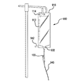
前述の態様のうちの任意の1つ以上と組み合わせて用いることができる本発明の別の例示的態様によれば、回収リザーバ上昇装置は、支持スタンド、回収リザーバ、送達チューブ及びコネクタを含む。回収リザーバは、リリーフチューブに流体連通している。さらに、回収リザーバは、ガスを両方向に通過させるように構成されたベント部を含み、かつ回収リザーバは、患者の胃からリリーフチューブを経由して逆流流体を回収するように構成されている。コネクタは、リリーフチューブ及び送達チューブにそれぞれ流体連通している。滑車は、支持スタンドと、回収リザーバに接続された紐状体とに接続されており、紐状体は、滑車を通り抜けかつ回収リザーバを上昇させるように構成されている。 According to another exemplary aspect of the present invention that can be used in combination with any one or more of the foregoing aspects, a collection reservoir raising device includes a support stand, a collection reservoir, a delivery tube, and a connector. The collection reservoir is in fluid communication with the relief tube. In addition, the collection reservoir includes a vent configured to allow gas to pass in both directions, and the collection reservoir is configured to collect a backflow fluid from the patient's stomach via a relief tube. The connector is in fluid communication with the relief tube and the delivery tube, respectively. The pulley is connected to a support stand and a string connected to the collection reservoir, and the string is configured to pass through the pulley and raise the collection reservoir.
前述の態様のうちの任意の1つ以上と組み合わせて用いることができる本発明の別の例示的態様によれば、回収リザーバは、リリーフチューブ、コネクタ、及び送達チューブを含む経腸栄養システムに関連して用いることができる。回収リザーバは、経腸栄養システムのリリーフチューブからの胃逆流物を受け入れるように構成されている少なくとも2つのチャンバを含む。 According to another exemplary aspect of the present invention that can be used in combination with any one or more of the foregoing aspects, the collection reservoir is associated with an enteral feeding system that includes a relief tube, a connector, and a delivery tube. Can be used. The collection reservoir includes at least two chambers configured to receive gastric reflux from the relief tube of the enteral feeding system.
前述の態様のうちの任意の1つ以上と組み合わせて用いることができる本発明の別の例示的態様によれば、回収リザーバであって、リリーフチューブ、コネクタ、及び送達チューブを含む経腸栄養システムに関連して用いるための回収リザーバは、経腸栄養システムの胃圧軽減チューブから胃逆流物を受け入れるように構成された円錘台形チャンバを含む。円錘台形チャンバは、硬質材料または軟質材料のいずれかでできている隔壁によって画定されている。該隔壁は、経腸栄養システムから受け入れた逆流物の容積を表すように構成された容積表示部をさらに含む。 In accordance with another exemplary aspect of the present invention that can be used in combination with any one or more of the foregoing aspects, an enteral feeding system comprising a collection reservoir, a relief tube, a connector, and a delivery tube A collection reservoir for use in connection with includes a frustum-shaped chamber configured to receive gastric reflux from a gastric pressure reducing tube of the enteral feeding system. The frustum-shaped chamber is defined by a septum made of either hard or soft material. The septum further includes a volume indicator configured to represent the volume of reflux received from the enteral feeding system.
前述の態様のうちの任意の1つ以上と組み合わせて用いることができる本発明の別の例示的態様によれば、胃圧軽減システムとともに用いるための回収リザーバ吊下装置は、投与容器、リリーフチューブ、送達チューブ、多方向コネクタ、及び回収リザーバを含む。投与容器は、投与チューブに接続されている。送達チューブは、投与チューブ及びリリーフチューブにそれぞれ流体連通している。多方向コネクタは、第1のアーム、第2のアーム及び第3のアームを有している。さらに、第1のアームはリリーフチューブに接続され、第2のアームは送達チューブに接続され、第3のアームは投与チューブに接続されている。回収リザーバは、リリーフチューブに流体連通している。回収リザーバは、ガスを両方向に通過させるように構成されたベント部を含む。回収リザーバは、患者の胃からリリーフチューブを経て逆流流体を回収するように構成されている。回収リザーバは、セルフセンタリング開口を備えたハンガータブを含み、かつ回収リザーバは、患者の胃から受け入れた逆流流体の容積を表すように構成された容積表示部を含む。 In accordance with another exemplary aspect of the present invention that can be used in combination with any one or more of the foregoing aspects, a collection reservoir suspension device for use with a gastric pressure relief system comprises a dosing container, a relief tube, A delivery tube, a multi-directional connector, and a collection reservoir. The administration container is connected to the administration tube. The delivery tube is in fluid communication with the administration tube and the relief tube, respectively. The multidirectional connector has a first arm, a second arm, and a third arm. Further, the first arm is connected to the relief tube, the second arm is connected to the delivery tube, and the third arm is connected to the dosing tube. The collection reservoir is in fluid communication with the relief tube. The collection reservoir includes a vent portion configured to pass gas in both directions. The collection reservoir is configured to collect the reflux fluid from the patient's stomach via a relief tube. The collection reservoir includes a hanger tab with a self-centering opening, and the collection reservoir includes a volume indicator configured to represent the volume of reflux fluid received from the patient's stomach.
前述の態様のうちの任意の1つ以上と組み合わせて用いることができる本発明の別の例示的態様によれば、胃圧軽減システムは、投与チューブに接続された投与容器、リリーフチューブ、送達チューブ、多方向コネクタ、回収リザーバ、及びドレインポートを含む。送達チューブは、投与チューブ及びリリーフチューブにそれぞれ流体連通している。多方向コネクタは、第1のアーム、第2のアーム及び第3のアームを有している。さらに、第1のアームはリリーフチューブに接続され、第2のアームは送達チューブに接続され、第3のアームは投与チューブに接続されている。回収リザーバは、リリーフチューブに流体連通している。さらに、回収リザーバは、ガスを両方向に通過させるように構成されたベント部を含み、かつ回収リザーバは、患者の胃からリリーフチューブを経て逆流流体を回収するように構成されており、回収リザーバは、患者の胃から受け入れた逆流流体の容積を表すように構成された容積表示部を含む。ドレインポートは、回収リザーバに接続されている。 According to another exemplary aspect of the present invention that can be used in combination with any one or more of the foregoing aspects, a gastric pressure relief system comprises a dosing container, a relief tube, a delivery tube connected to the dosing tube. A multi-directional connector, a collection reservoir, and a drain port. The delivery tube is in fluid communication with the administration tube and the relief tube, respectively. The multidirectional connector has a first arm, a second arm, and a third arm. Further, the first arm is connected to the relief tube, the second arm is connected to the delivery tube, and the third arm is connected to the dosing tube. The collection reservoir is in fluid communication with the relief tube. In addition, the collection reservoir includes a vent configured to pass gas in both directions, and the collection reservoir is configured to collect backflow fluid from the patient's stomach via a relief tube, A volume indicator configured to represent the volume of reflux fluid received from the patient's stomach. The drain port is connected to the collection reservoir.
前述の態様のうちの任意の1つ以上と組み合わせて用いることができる本発明の別の例示的態様によれば、経腸栄養中に胃圧を軽減するための装置は、栄養チューブと投与容器に接続された投与チューブとの間に介装されている。上記装置は、多方向コネクタ、 流体送達チューブ、リリーフチューブ、及び回収リザーバを含む。流体送達チューブは、栄養チューブに接続されている。多方向コネクタは、投与チューブを流体送達チューブに接続するように構成されている。流体送達チューブは、栄養チューブが患者に流体栄養剤を供給しているときに多方向コネクタを患者の胃の高さに配置するのに必要な最小長さによって規定される第1の長さを有する。リリーフチューブは、多方向コネクタに接続されている。回収リザーバはリリーフチューブに接続されており、回収リザーバは、患者の胃からリリーフチューブを経て逆流流体を回収するように構成されている。 According to another exemplary aspect of the present invention that can be used in combination with any one or more of the foregoing aspects, an apparatus for reducing gastric pressure during enteral nutrition includes a feeding tube and a dosing container. It is interposed between the administration tube connected to. The apparatus includes a multidirectional connector, a fluid delivery tube, a relief tube, and a collection reservoir. The fluid delivery tube is connected to the feeding tube. The multidirectional connector is configured to connect the administration tube to the fluid delivery tube. The fluid delivery tube has a first length defined by the minimum length required to place the multi-directional connector at the level of the patient's stomach when the feeding tube is supplying fluid nutrient to the patient. Have. The relief tube is connected to the multidirectional connector. The collection reservoir is connected to the relief tube, and the collection reservoir is configured to collect the backflow fluid from the patient's stomach via the relief tube.
前述の態様のうちの任意の1つ以上と組み合わせて用いることができる本発明の別の例示的態様によれば、経腸栄養中に胃圧軽減を提供するための方法において、経腸栄養は、投与チューブを経由して栄養チューブに流体栄養剤を送達する投与容器を用いて実施され、投与チューブと栄養チューブとの間には胃圧軽減システムが介装されている。上記方法は、栄養チューブを患者に挿管するステップと、栄養チューブの近位端と患者の胃の高さにある垂直平面との間の近似的な最短距離を測定するステップと、流体送達チューブセグメントの長さを近似的に測定最短距離に設定するステップと、流体送達チューブを栄養チューブ及び多方向コネクタにそれぞれ結合させるステップと、患者に流体栄養剤を供給するステップとを含む。栄養チューブは、患者の体外に近位端を有する。 According to another exemplary aspect of the present invention that can be used in combination with any one or more of the foregoing aspects, in a method for providing gastric pressure relief during enteral nutrition, enteral nutrition comprises: It is carried out using a dosing container that delivers a fluid nutrient to the feeding tube via the dosing tube, and a gastric pressure relief system is interposed between the dosing tube and the feeding tube. The method includes intubating a feeding tube into a patient, measuring an approximate minimum distance between a proximal end of the feeding tube and a vertical plane at the level of the patient's stomach, and a fluid delivery tube segment The fluid delivery tube is coupled to the feeding tube and the multi-directional connector, respectively, and the patient is supplied with fluid nutrients. The feeding tube has a proximal end outside the patient's body.
前述の態様のうちの任意の1つ以上と組み合わせて用いることができる本発明の別の例示的態様によれば、胃圧軽減システムは、投与容器、リリーフチューブ、送達チューブ、多方向コネクタ、及び回収リザーバを含む。投与容器は、投与チューブに接続されている。送達チューブは、投与チューブ及びリリーフチューブにそれぞれ流体連通している。多方向コネクタは、第1のアーム、第2のアーム及び第3のアームを有している。さらに、第1のアームはリリーフチューブに接続され、第2のアームは送達チューブに接続され、第3のアームは投与チューブに接続されている。回収リザーバは、リリーフチューブに流体連通している。さらに、回収リザーバは、ガスを両方向に通過させるように構成されたベント部を含む。ベント部は、該ベント部を通過する液体の流れを抑制するように構成された1若しくは複数のメンブレンを含み、回収リザーバは、患者の胃からリリーフチューブを経て逆流流体を回収するように構成されている。 According to another exemplary aspect of the present invention that can be used in combination with any one or more of the foregoing aspects, a gastric pressure relief system includes a dosing container, a relief tube, a delivery tube, a multi-directional connector, and Includes a collection reservoir. The administration container is connected to the administration tube. The delivery tube is in fluid communication with the administration tube and the relief tube, respectively. The multidirectional connector has a first arm, a second arm, and a third arm. Further, the first arm is connected to the relief tube, the second arm is connected to the delivery tube, and the third arm is connected to the dosing tube. The collection reservoir is in fluid communication with the relief tube. Further, the recovery reservoir includes a vent portion configured to allow gas to pass in both directions. The vent portion includes one or more membranes configured to inhibit the flow of liquid through the vent portion, and the collection reservoir is configured to collect the backflow fluid from the patient's stomach via a relief tube. ing.
開示されているシステム、方法及び装置の追加的な特徴及び利点について、以下の詳細な説明及び図面で説明し、明らかにする。 Additional features and advantages of the disclosed systems, methods and apparatus will be described and elucidated in the following detailed description and drawings.
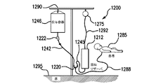
図面を参照すると、経腸栄養及び胃圧軽減/吸引器具の種々の実施形態が開示されている。図1に示す例示的な経腸栄養システム100に見られるように、選択された栄養剤が入っている経腸投与容器146が、支持スタンド130から吊り下げられている。当業者に理解されるように、本明細書に開示及び説明されている実施形態に関連して、他の経腸栄養システム構造及び構成を用いることもできる。経腸投与容器146から投与チューブ142を介して栄養剤を送達する流速は、経腸栄養ポンプ148の使用と投与チューブセットクランプ150の使用とを組合せて達成することができる。栄養剤の流速は、ドリップチャンバ及びチューブクランプ(例えば、ローラークランプまたは他の調節可能なクランプ)の組合せにより制御される重力供給方式によって達成することもできる。
Referring to the drawings, various embodiments of enteral nutrition and gastric pressure reducing / aspiration devices are disclosed. As seen in the exemplary
本明細書に記載の実施形態例に対する様々な改変形態及び変更形態は、当業者に明らかであろうということを理解されたい。そのような改変形態及び変更形態は、本発明の主題の趣旨及び範囲から逸脱することなく、かつその意図される利点を損なうことなく、作り出すことができる。したがって、そのような改変形態及び変更形態は、添付の特許請求の範囲に含まれるものとする。また、各独立請求項のシステム、装置及び方法に従属請求項の特徴を具現化することができることも理解されたい。 It should be understood that various modifications and changes to the example embodiments described herein will be apparent to those skilled in the art. Such modifications and variations can be made without departing from the spirit and scope of the present subject matter and without diminishing its intended advantages. Accordingly, such modifications and changes are intended to be included within the scope of the appended claims. It should also be understood that the features of the dependent claims may be embodied in the systems, devices and methods of each independent claim.
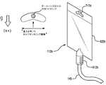
本明細書において用いられる「流体」なる語は、ガス及び液体の両方の物理状態を指し、かつ含む。図面を参照すると、胃圧軽減(胃減圧とも呼ばれる)器具の種々の実施形態が開示されている。以下で詳細に説明するように、図1の胃圧軽減システム110は、経腸投与チューブ142と経腸栄養チューブ138(例えば、鼻腔内チューブ、経口胃チューブ、胃瘻チューブなど)との間に介装されており、かつ経腸投与チューブ142を経腸栄養チューブ138に接続している。胃圧軽減システム110は、コネクタ装置135を用いて栄養チューブ138に接続されており、コネクタ装置135は、標準的な経腸栄養コネクタ装置であってよい。胃圧軽減システム110は、通常、逆流物回収リザーバ112を含み、これは、以下で詳細に説明するように、胃圧軽減中に患者の胃からの逆流物(すなわち、ガス及び/または液体)を受け入れるように構成されている。図1では、回収リザーバ112は、ガスベント部114を通して周囲の大気へベントされ、かつハンガータブ116によって支持スタンド130から吊り下げられている。リリーフチューブ145の或るセグメントが、回収リザーバ112をYコネクタ120などのコネクタに接続する;リリーフチューブのクランプ機構122は、Yコネクタ120と回収リザーバ112との間におけるガス及び液体の流れを選択的に制御するために用いることができる。流体送達チューブ144及び投与チューブ142は、Yコネクタ120にも接続されており、Yコネクタ120と栄養チューブ138との間における流れを阻止するために、栄養剤供給ラインのクランプ機構139を選択的に用いることができる。
As used herein, the term “fluid” refers to and includes the physical state of both gases and liquids. Referring to the drawings, various embodiments of gastric pressure reducing (also called gastric decompression) devices are disclosed. As described in detail below, the gastric
図1に示したような胃圧軽減システム110には回収リザーバ112が含まれ、回収リザーバ112は、周囲の大気圧にベントされる。空気がリリーフチューブ145及び流体送達チューブ144を通って経腸栄養チューブ138内に導入することを回避するために、胃圧軽減システム110は、リリーフチューブ145内に液体(例えば、栄養剤または他の液体)の小さな柱を提供するように構成されている。このことは、Yコネクタ120を患者の胃の高さかまたはそれより僅かに下に適切に配置することによって実現される。参考のため及び説明のために、患者の胃の高さは図1中に線155によって示されている。Yコネクタ120が患者の胃の高さ155(または例えば患者の中腋窩線)またはそれよりも低い位置にある限り、リリーフチューブ145に液体(例えば、栄養剤または他の液体)の小さな柱が入り、該柱のメニスカスが概ね図1の線153に(通常は患者の身体状態に応じて、胃の高さ155に極めて近接して、または胃の高さ155と同じ高さに)維持してリリーフチューブ145内に保留され続ける。この流体柱は、空気が流体送達チューブ144及び最終的に経腸栄養チューブ138に吸い込まれることを防止する。
The gastric
Yコネクタ120は、Y字型のコネクタであるのが好ましいが、投与チューブ142、流体送達チューブ144及びリリーフチューブ145間の流体連通が維持される限り、当分野で知られているかまたは用いられている他の多方向コネクタもまた適している。流体送達チューブ144は、投与チューブ142からYコネクタ120を経て栄養剤を受け入れ、該栄養剤を経腸栄養チューブ138に送達する。さらに、胃圧が過剰な状態では、流体送達チューブ144は、逆流物(ガス及び/または液体)を、Yコネクタ120を通って圧力リリーフチューブ145内へ(及び必要であれば回収リザーバ112内へ)逆方向に通過させる。流体送達チューブ144を通過する逆流ガスは、リリーフチューブ145内に導かれ、上向きに回収リザーバ112、ガスベント部114を通過し、周囲の大気に放出される。
The
いくつかの実施形態では、Yコネクタ120をユーザまたは患者の胃の高さまたはそれよりも下の位置に維持するため、さらにまた、チューブ管理を助ける(例えば、絡まらないようにする、患者の睡眠、歩行活動などを妨げない)ために、追加的な装置及び/または手段を取り入れることができる。
In some embodiments, in order to maintain the
例えば、図1に示したように、Yコネクタ120の一部として、またはYコネクタ120を衣服、パジャマ、またはベッド用リネンに固定的に保持するように適合されているような、クリップ127(例えば衣類用クリップ)または他の接続手段を組み込むことができる。クリップ127は、Yコネクタ120の配置を維持するのを助ける。別の実施形態では、接続手段は、Yコネクタ120の配置を維持するために患者の皮膚に直接付着する親水コロイドまたは他の適切な接着剤であってよい。いくつかの実施形態では、Yコネクタ120のためにより重い構造材料を用いるか、またはYコネクタ120に重りを配置するかまたは取り付けることにより、その配置を患者の胃の高さまたはそれよりも下の位置に維持することを助ける。したがって、経腸栄養システム100/胃圧軽減システム110には、Yコネクタ120の位置を有利に維持するための位置決め装置が備わっている。
For example, as shown in FIG. 1, a clip 127 (e.g., adapted to hold the
さらに、投与チューブ142内へ(ひいては投与容器146内へ)戻る逆行する流れを阻止するために、経腸栄養システム100に一方向チェックバルブ129または他の逆流防止手段を組み入れることができる。一方向チェックバルブ129は、Yコネクタ120の1つのアーム内の内部バルブであってよく、またはYコネクタ120と投与チューブセグメント142との間に配置させることができる。一方向チェックバルブ129は、一方向のみ(すなわち、リリーフチューブ145及び/または流体送達チューブ144に向かう)流れを許容するものであり、例えば、経腸栄養システムが「重力モード」で(すなわち、流体ポンプなどを用いずに)操作されるときに用いることができる。
In addition, a one-
図1の例示的な構成に関して既に説明したように、Yコネクタ120は、(a)Yコネクタ120の第1のアームリリーフチューブ145、(b)Yコネクタ120の第2のアーム内に収容される流体送達チューブ144、及び(c)Yコネクタ120の第3のアーム内に収容される投与チューブ142間の流体連通を画定しかつ許容する。
As already described with respect to the exemplary configuration of FIG. 1, the
前方栄養供給流れ構成では、栄養剤などが、投与容器146から投与チューブ142を通り、Yコネクタ120の第3のアームを通って流れる。その後、流体は、Yコネクタ120の下部すなわち第2のアームを通過し、流体送達チューブ144を通り、コネクタ装置135を通って、栄養チューブ138に流入する。上記したように、送達チューブは、流体送達チューブ144と栄養チューブ138の組合せであってよく、あるいは、送達チューブは、流体を患者に送達して栄養を与える単一の構成部分であってもよく、それならばコネクタ装置135は不要である。送達チューブは、近位端及び遠位端を有し、送達チューブの近位端は、Yコネクタ120の第2のアームに接続されている。さらに、逆向きの回収構成では、胃内容物などが、栄養チューブ138、コネクタ装置135を通過し、流体送達チューブ144に流入する。流体送達チューブ144から、胃内容物は、Yコネクタ120の第2のアーム、Yコネクタ120の第1のアームを通過し、リリーフチューブ145に流入する。その後、胃内容物は回収リザーバ112に入る。リリーフチューブ145は、流体送達チューブ144の遠位端と投与容器146との間、または送達チューブの遠位端と投与容器146との間に介装されている。同様に、胃内容物が患者に戻ると、胃内容物は回収リザーバ112からリリーフチューブ145を通ってYコネクタ120の第1のアームに流入する。その後、流体は、Yコネクタ120の第2のアームを通って流体送達チューブ144に、コネクタ装置135を通って栄養チューブ138に、それぞれ流入する。
In the forward nutrient supply flow configuration, nutrients and the like flow from the
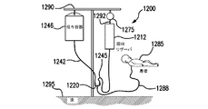
いくつかの胃圧軽減システム実施形態は、(例えばNICU環境などにおいて)新生児、乳児及びその他の同様の患者を治療するように構成され、かつ胃圧軽減システムに組み込まれているチューブ、例えば、胃圧軽減システムコネクタと患者との間において必要とされるチューブの長さを最小にしかつ/または大いに減少させるように構成されている。図2Aないし図2Cは、新生児、乳児、または他の小さな子供の経腸栄養のためのいくつかの例示的なシナリオを示している。図2Aでは、患者の腹部の瘻孔を介して栄養チューブ238が液体栄養剤を供給する胃瘻チューブ栄養システム200を用いて栄養供給されている子供が示されている。流体送達チューブ244が栄養チューブ238を胃圧軽減システム210に接続しており、胃圧軽減システム210にはYコネクタ220も含まれており、Yコネクタ220には投与チューブ242及びリリーフチューブ245も接続されている。投与チューブ242は、投与容器246からポンプ248、重力などによって栄養剤などを送達する。投与容器246からの栄養剤の流れを調整するのを助けるために、ローラークランプまたは他のクランプ機構231を用いることができる。リリーフチューブ245は、Yコネクタ220をリザーバ212に接続し、この場合もやはり、Yコネクタ220とリザーバ212との間の流れを制御するために、リリーフチューブ245に結合されたローラークランプ222を用いることができる。胃圧軽減システム210は、コネクタ装置235を用いて栄養チューブ238に接続されており、コネクタ装置235は、標準的な経腸栄養コネクタ装置であってよい。
Some gastric pressure relief system embodiments are configured to treat neonates, infants, and other similar patients (eg, in a NICU environment) and are tubes incorporated into the gastric pressure relief system, eg, stomach It is configured to minimize and / or greatly reduce the length of tubing required between the pressure relief system connector and the patient. 2A-2C illustrate several exemplary scenarios for enteral nutrition for newborns, babies, or other small children. In FIG. 2A, a child is shown being fed using a gastrostomy
図2Bは、同様に、同等の栄養システム200を示しており、ここでは、患者の鼻から栄養チューブ238が延びている。栄養チューブ238は、コネクタ装置235を介して、胃圧軽減システム210の流体送達チューブ244に接続されており、胃圧軽減システム210にはYコネクタ220も含まれる。投与チューブ242及びリリーフチューブ245もまた、Yコネクタ220に接続されている。投与チューブ242は、投与容器246からポンプ248を通って栄養剤を送達する。ローラークランプまたは他のクランプ機構231が、投与容器246からの流量の調節を助ける。リリーフチューブ245は、Yコネクタ220をリザーバ212に接続し、さらに、リリーフチューブ245に結合されたローラークランプ222を用いて、Yコネクタ220とリザーバ212との間の流れを制御する。胃圧軽減システム210は、コネクタ装置235を用いて栄養チューブ238に接続されている。図2Cは、図2A及び図2Bに関連して説明したものと同じような栄養供給及び胃圧軽減システムとともに経口胃栄養チューブ238が用いられているシステムを示している。
FIG. 2B similarly shows an
図2A〜図2Cの実施形態では、Yコネクタ220は、患者の胃の高さまたはそれよりも下の位置に維持されなければならない(上記したように、いくつかの実施形態は、その趣旨で1若しくは複数の適切な配置時注意喚起部を含むことができる)。しかし、体の小さな患者、低い送達流速、及びそのような患者に投与するのに用いられるいくつかの栄養剤(例えば母乳)の性質が、体の大きな患者に見られるのとは異なる状況をもたらす。図2Aないし図2Cの実施形態では、胃圧軽減システムをプライミングするのに必要な栄養剤の量が減少するかまたは最小限に抑えられるように、栄養チューブ238及び流体送達チューブ244は、流体送達チューブ244の長さを減少させる(いくつかの実施形態では、最小限に抑える)大きさに形成されている。
In the embodiment of FIGS. 2A-2C, the
図2A〜図2Cの例示的なシステムにおける栄養チューブ238及び流体送達チューブ244の組合せの最小長さは、栄養チューブ238の出口点(すなわち、患者の身体から栄養チューブ238が出る点。例えば、鼻孔(NGチューブの場合)や瘻孔(胃栄養チューブ(Gチューブ)、経皮空腸瘻栄養チューブ(Jチューブ)、胃空腸瘻栄養チューブ(GJチューブ)、または経皮内視鏡的胃瘻チューブ(PEGチューブ)が用いられる場合)などの身体開口部)と、患者の胃の高さの平面(場合によっては、すなわち、腹部の前(腹側)部分及び背中の後部(背部)部分に対して胃の位置の真下の中腋窩線付近に位置する冠状(または前頭)平面との交点)との間の最短距離である。
The minimum length of the
流体送達チューブ244の長さを最小にするかまたは実質的に減少させることによって、図の胃圧軽減システムの実施形態は、使用のためにシステムをプライミングするのに必要な栄養剤の量を大いに減少させる。さらに、チューブを短くした胃圧軽減システムの実施形態の、大幅に短くしたチューブにおいて、少量の逆流物により容易に気付くことになるので、そのようなチューブを短くした胃圧軽減システムの実施形態は、小さな患者において胃圧及び/または逆流が存在するときに、看護師などの介護者に対して改良されたフィードバックを与えることができる。
By minimizing or substantially reducing the length of the
このチューブを短くした実装を用いた経腸栄養中に胃圧軽減を提供する方法は、投与チューブ242を経て経腸栄養チューブに流体栄養剤を送達する流体栄養剤源を用いて経腸栄養が実施されるときに実施することができる。投与チューブ242と経腸栄養チューブ238との間には、胃圧軽減システム210が介装されている。上記方法は、患者に経腸栄養チューブ238を挿管することから始まり、ここで、経腸栄養チューブ238は、患者の体外に近位端を有する。その後、経腸栄養チューブ238の近位端と患者の胃の高さにある垂直平面との間の近似的な最短距離を測定するかまたは推定し、例えば、流体送達チューブ244を適切な長さに切断するかまたは事前に測定された長さを有する流体送達チューブ244を選択することによって、流体送達チューブ244の長さを近似的に測定最短距離に設定する。その後、流体送達チューブ244を経腸栄養チューブ238及びYコネクタ220(または他の接続手段)にそれぞれ結合し、その後、流体栄養剤を患者に供給する。
A method for providing gastric pressure relief during enteral nutrition using a shortened implementation of this tube is that enteral nutrition can be achieved using a fluid nutrient source that delivers hydrotrophic agent via
図面に示されている装置及び当該装置を用いて実施される方法は、患者の栄養供給及びケアを助けるために様々な形で用いることができる。以下の1若しくは複数の操作モード、プロセス、方法などの開示は、限定的なものではないが、説明のためにのみ与えられている。 The devices shown in the drawings and the methods performed using the devices can be used in a variety of ways to assist with patient nutrition and care. The following disclosure of one or more operating modes, processes, methods, etc. is provided for illustration only, but not limitation.
図1の胃圧軽減システム110を説明のために用いると、投与容器146は、投与チューブ142及び任意の他の栄養剤供給装置とともに、支持スタンド130などから吊り下げられている。回収リザーバ112は、例えば同様に支持スタンド130から吊り下げられているような投与容器146と同じ高さに吊り下げられている。リリーフチューブ145上のクランプ機構122は完全に閉じているので、Yコネクタ120と回収リザーバ112との間の流体の流れが阻止される。
Using the gastric
その後、流体送達チューブ144を例えば流体栄養剤でプライミングするのと同時に、投与チューブ142をYコネクタ120に接続する。プライミングは、場合によっては、Yコネクタ120よりも僅かに上の高さまでリリーフチューブ145をプライミングするステップを含むこともできる。上記したように、いくつかの実施形態では、流体送達チューブ144(及び、調節可能であれば、栄養チューブ138も)の長さを短くすることによって、必要な栄養剤の量が減少する(または最小限に抑えられる)。いくつかの方法では、栄養チューブ138の出口点と患者の胃の高さとの間の最小距離を測定または近似することができ、その後、最小距離の測定値または近似値に基づいて、流体送達チューブの長さを選択する(または、場合によっては、流体送達チューブの長さを切断により短縮する)。このとき、投与チューブ142と栄養チューブ138との間の流れを阻止するために、栄養剤供給ラインのクランプ機構139も閉鎖される。
Thereafter, the
その後、流体送達チューブ144を栄養チューブ138に接続する。投与容器146から栄養チューブ138(ひいては患者)への栄養剤の流れを許容するために、クランプ機構139を(部分的に、または完全に)開放する。その後、胃圧軽減システム110において最初の平衡状態に到達させるため、及びその後に流体送達チューブ144及びYコネクタ120を通ってリリーフチューブ145と、必要であれば回収リザーバ112(本発明の種々の実施形態のうちの任意の実施形態の回収リザーバであってよい)への逆流物の流れを許容するために、クランプ機構122を(この場合もやはり、部分的に、または完全に)開放する。リリーフチューブ145内のフォーミュラのノミナル高さは、通常、患者の胃の高さを僅かに上回ることになる。栄養供給が非常に少量である患者(例えば新生児)においては、クランプ機構122を開放する前、またはクランプ機構122を完全に開放する前に、栄養剤の流れを確立するのにかなり長い時間が掛かることがある。リリーフチューブ145及び回収リザーバ112内の液面は、連続的に及び/または頻繁に上下動し得る。
Thereafter, the
クランプ機構及び制御 Clamp mechanism and control
リリーフセグメント145には、クランプ機構122を設けることができる。いくつかの実施形態では、クランプ機構122は、(例えば、さらなる排出または過剰栄養供給を回避するため、患者へのリザーバ内容物の戻りの速度を遅くするため、など)回収リザーバ112と患者との間の内容物の流れの速度を選択的にかつ調節可能に阻止、制限、及び/または測定するために用いることができるローラークランプ222である。いくつかのローラークランプ実施形態では、リリーフチューブ145などのチューブを通る流体(すなわち、液体及びガス)の流量を調節するために、チューブは、チャンネルが形成されたホルダ内に保持され、ホルダの互いに対向する側壁間に取り付けられたホイールなどが、ホイールの回転位置に左右される調節可能な圧力(例えば、変形または圧迫圧力)をチューブに印加する。ホイールを回転させ、所望の位置に確実にロックするために、スプリングデテントを備えたラチェットホイールをホイールに取り付けることができる。可変クランプ機構(例えば、ローラークランプ222)の設定に加えて、ローラークランプ222を完全に開放または完全に閉鎖するように調節して、器具の設定を助けることもできる。
The
他の実施形態では、図1のクランプ機構122は、2値オンオフ型クランプであってよい。様々な実施形態では、クランプ機構122は、リリーフチューブ145を完全に閉じて、胃圧軽減システム110を動作不能にさせることができる。
In other embodiments, the
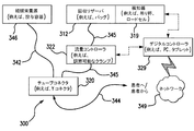
ローラークランプ222または他の調節可能なクランプ機構は、1若しくは複数の因子または基準に基づいて流体の流れを制御する自動化されたシステム内の流量コントローラとしての機能を果たすことができる。例えば、図3Aは、システム300のブロック図であり、対応する図3Bは、システム300の斜視図を示しており、ここでは、経腸栄養源346(例えば、経腸投与容器)から栄養剤などが投与チューブ342を経てYコネクタ220などのチューブコネクタ320へ供給される。コネクタ320は、今度は、栄養剤を流体送達チューブ344を経て患者へ供給する。逆流物は、患者から流体送達チューブ344を経てコネクタ320を通ってリリーフチューブ345を経て回収リザーバ312に至るまで流れることができ、回収リザーバ312は、バッグなどであってもよい。流量コントローラ322は、回収リザーバ312及び患者に出入りする逆流物の流量を調節するように構成されている。システム300では、流量コントローラ322は、デジタルコントローラ329に接続されており、デジタルコントローラ329は、PC、タブレット、または別の適切な制御装置であってよい。検知器319が、回収リザーバ312に結合され、回収リザーバ312の1若しくは複数の物理特性、例えば重量を(例えば、吊下げ秤、ロードセルなどを用いて)検知するように構成することができる。他の実施形態では、流量コントローラ322を制御するために、リリーフチューブ345内の圧力を測定し、閾値レベルを検知することができる。検知器319は、信号を(無線で、ブルートゥース(登録商標)によって、または有線通信で)デジタルコントローラ329に送信し、デジタルコントローラ329は、信号を処理することにより、流量コントローラ322の設定値を決定する。デジタルコントローラ329は、ネットワーク349を介して他の場所(例えばナースステーション)にデータを伝達することもできる。
The
胃残量バルブ及び方法 Stomach balance valve and method
経腸栄養システムは、患者のケア及び/または治療の他の態様、例えば栄養供給速度及び患者の胃内容物蓄積を測定しかつ調整することを助けるのによく適している。胃残量(「GRV」)測定は、救命救急栄養療法において、栄養不耐性などの状態、吸引(及び吸引肺炎)のリスク、及び胃内容物排出の指標として一般的に行われている。GRVレベルは、経腸栄養治療の開始時にはより高く、耐性が増加し、腸の収縮が回復し、患者が臨床的に回復するにつれて低下する傾向がある。臨床的には、GRVの測定においては標準化が欠如している。多くの現行のGRV測定手順は、厄介で、使いにくく、面倒で、不快である。「開放」系(例えば、患者の吸引された胃内容物が外部環境に開かれているもの)を用いるものは、臨床医及び介護者が患者の体液に暴露される危険がある。そのような患者の体液への暴露の可能性はまた、米国の疾病管理予防センター(CDC)及び国立労働安全衛生研究所(NIOSH)により追加の個人用防護具(PPE)を必要とする。以前の方法(シリンジによる取り出し及びビーカーでの回収など)を用いてGRVをチェックすることは、時間の掛かる工程でもある。多くの病院施設は、患者のGRVを1日につき4〜6回(例えば、4〜6時間毎に)評価する。例えば、米国静脈経腸栄養学会(ASPEN)は、胃から栄養供給される患者に対して、最初の48時間の間は胃内残存物を4時間毎にチェックすることを推奨している。同じくASPENによれば、GRVレベルが250mLよりも大きいときには臨床的介入を考慮すべきであり、GRVが500mLでは経腸栄養剤を停止すべきである。したがって、GRVを容易に評価してかつモニタすることは、臨床的に非常に有益である。吸引された胃内容物は、正常な消化管機能、保護及び消化に重要な必須の胃内容物を含むので、回収されるかまたは保持されたら、吸引された胃内容物を患者に戻すことが重要である。吸引された胃内容物を戻すことはまた、患者が全ての規定された栄養剤(例えば、カロリー、電解質など)及び薬剤を受け入れていることを確実にする。 The enteral nutrition system is well suited to assist in measuring and adjusting other aspects of patient care and / or treatment, such as the rate of nutrient delivery and patient gastric content accumulation. The measurement of the remaining amount of the stomach (“GRV”) is generally performed in lifesaving emergency nutrition therapy as a condition such as nutrient intolerance, the risk of aspiration (and aspiration pneumonia), and an index of gastric emptying. GRV levels are higher at the start of enteral nutrition treatment and tend to decrease as tolerance increases, bowel contraction is restored, and patients recover clinically. Clinically, standardization is lacking in the measurement of GRV. Many current GRV measurement procedures are cumbersome, cumbersome, cumbersome and uncomfortable. Those using “open” systems (eg, where the patient's aspirated stomach contents are open to the external environment) are at risk for the clinician and caregiver to be exposed to the patient's bodily fluids. The potential exposure of such patients to body fluids also requires additional personal protective equipment (PPE) by the US Centers for Disease Control and Prevention (CDC) and the National Occupational Safety and Health Institute (NIOSH). Checking the GRV using previous methods (such as taking out with a syringe and collecting with a beaker) is also a time consuming process. Many hospital facilities evaluate a patient's GRV 4-6 times per day (eg, every 4-6 hours). For example, the American Society for Parenteral and Enteral Nutrition (ASPEN) recommends that patients fed from the stomach be checked for gastric residue every 4 hours for the first 48 hours. Also according to ASPEN, clinical intervention should be considered when the GRV level is greater than 250 mL, and enteral nutrition should be stopped when the GRV is 500 mL. Therefore, it is very beneficial clinically to easily evaluate and monitor GRV. The aspirated stomach contents contain essential gastric contents essential for normal gastrointestinal function, protection and digestion, so that once collected or retained, the aspirated stomach contents can be returned to the patient. is important. Returning the aspirated stomach contents also ensures that the patient has received all defined nutrients (eg, calories, electrolytes, etc.) and medications.
以前のGRV測定装置及び方法は、「パッシブGRV測定」法に依存していた。これは、バッグまたは他の容器が、患者の胃、中腋窩線または他の解剖学的マーカの高さよりも低い高さまで下げられ、その後、重力が、患者の胃内容物を容器内に排出する(吸い上げる)ように作用するというものである。容器の中身は、測定後に、処分するか、患者の胃に「パッシブに」戻す(すなわち、解剖学的マーカよりも高い位置に配置された容器から流出し、重力により容器の中身を容器から患者の胃へ移動させる)か、またはこの2つの組合せを行うことができる。本明細書に開示されている実施形態では、パッシブGRV測定は、「アクティブ」GRV測定と区別されることになる。アクティブGRV測定では、所与の経腸栄養システム内などにおいて胃内容物を移動させるために、人為的力が印加される。このアクティブGRV測定を実施するための装置のいくつかの実施形態について説明する。 Previous GRV measurement devices and methods relied on the “passive GRV measurement” method. This is because the bag or other container is lowered to a height that is lower than the height of the patient's stomach, mid-axillary line or other anatomical marker, and then gravity drains the patient's stomach contents into the container. It works to (suck up). The contents of the container are disposed of after measurement or returned “passively” to the patient's stomach (i.e., spilled from a container positioned higher than the anatomical marker, and the contents of the container are removed from the container by gravity. To the stomach) or a combination of the two. In the embodiments disclosed herein, passive GRV measurements will be distinguished from “active” GRV measurements. In active GRV measurements, an artificial force is applied to move stomach contents, such as within a given enteral feeding system. Several embodiments of an apparatus for performing this active GRV measurement are described.
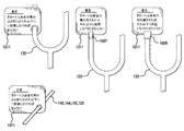
胃残量測定を行うように構成された装置のいくつかの実施形態(そのうちの1つ以上が図4に示されている)では、胃残量測定装置400は、経腸栄養システム100/200及び回収リザーバ412とともに用いるためのものであり、その機能は、既に上記されており、当業者によく知られている。回収リザーバ412は、ベント部414と、第2の(中間)リリーフチューブセグメント466及び第1のバイパスチューブセグメント468に接続された第1のリリーフチューブセグメント445とを有する。同様に、第3のリリーフチューブセグメント488は、第2の(中間)リリーフチューブセグメント466及び第2のバイパスチューブセグメント470に接続されている。第1のリリーフチューブセグメント445と、第2のリリーフチューブセグメント466と、第1のバイパスチューブセグメント468の接合部は、任意の適切な3ポートのデバイスまたはその等価物、例えばYコネクタ490であってよい。同様に、第3のリリーフチューブセグメント488と、第2のリリーフチューブセグメント466と、第2のバイパスチューブセグメント470の接合部は、任意の適切な3ポートのデバイスまたはその等価物、例えばYコネクタ492であってよい。クランプ機構422は、第2の(中間)リリーフチューブセグメント466に取り付けられており、第2の(中間)リリーフチューブセグメント466を通る流体の流れの選択的閉塞を許容する任意の適切なクランプまたは他のクランプ手段であってよい。図1のリリーフチューブ145が図1のYコネクタ120に接続しているのと全く同じように、第3のリリーフチューブセグメント488をYコネクタ120に接続することができる。
In some embodiments of the device configured to perform gastric residue measurement (one or more of which are shown in FIG. 4), the gastric
第1のバイパスチューブセグメント468及び第2のバイパスチューブセグメント470は、アクセスポート481にも接続されており、適切なYコネクタ486、あるいは同等の結合装置または構造体であってもよい。いくつかの実施形態におけるポート481は、流体除去及び再導入装置、例えば、所望通り、第2のバイパスチューブセグメント470から逆流物を吸引することができ、逆流物を第1のバイパスチューブセグメント468内へポンピングすることもできるような、シリンジ410または他の流体吸引及びポンピング(すなわち、「人為的力印加」)手段によってアクセス可能である。シリンジ410上の容積表示部を用いて、患者から回収された逆流物の量を測定することができる。例えば、50mLのシリンジを用い、容積表示部を用いて逆流物を測定することによって逆流物を除去及び測定することができる。逆流物の量がシリンジ410の容量を超えている場合、逆流物が患者に再導入されるまで、逆流物を測定して容器に入れることができる(例えば、50mLシリンジが4つ、37mLシリンジが1つであれば、237mLの胃残量測定値を示すことになる)。別の実施形態例では、流体除去及び再導入装置は、シリンジ410と、容積表示部を含む測定容器とを含むことができる。シリンジ410を用いて、アクセスポート481を通して逆流物を除去しかつ除去された逆流物を測定容器に入れることができる。その後、臨床医は、測定容器上に配置された容積表示部を用いて胃残量測定値を求めることができる。
The first
第1のバイパスチューブセグメント468は、第1のチェックバルブ469、または他の方向制限手段であって、流体がアクセスポート481から第1のリリーフチューブセグメント445を経て回収リザーバ412へ(矢印で示されているように)流れることのみを許容するものを有する。同様に、第2のバイパスチューブセグメント470は、第2のチェックバルブ471、または他の方向制限手段であって、流体が患者から第3のリリーフチューブセグメント488を経てアクセスポート481へ(矢印で示されているように)流れることのみを許容するものを有する。
The first
操作中に、装置400を用いてアクティブGRV測定が行われる場合には、流体(すなわちガス及び/または液体)が第2の(中間)リリーフチューブセグメント466を通過することを阻止するために、クランプ機構422は閉じられている。シリンジ410または他の流体吸引器具(すなわち「人為的力印加手段」)をアクセスポート481に(例えばENFit接続構成を用いて)接続し、その後、装置400から第2のバイパスチューブセグメント470及び第3のリリーフチューブセグメント488を経て逆流物を取り除く。除去されるべき(かつ恐らくは測定されるべき)逆流物及び/または胃内容物が相当量存在する場合は、ポート481を用いて複数サイクルの流体吸引を行うことができ、あるいはより大きな流体吸引器具410を用いることができる。第2のチェックバルブ471は、第2のチェックバルブ471よりも「下方」から流体(すなわち、第2のバイパスチューブセグメント470における第2のチェックバルブ471よりも下方の、第2の(中間)リリーフチューブセグメント466におけるクランプ機構422よりも下方の、第3のリリーフチューブセグメント488内の、及び/または第3のリリーフチューブセグメント488に接続された任意の源、例えば患者の胃などからの、任意の流体)が流れることを許容する。この方式での装置400からの流体の吸引は、第1のチェックバルブ469よりも「上方」に存在する如何なる逆流物(すなわち、第1のバイパスチューブセグメント468における第1のチェックバルブ469よりも上方の、第2の(中間)リリーフチューブセグメント466におけるクランプ機構422よりも上方の、第1のリリーフチューブセグメント445内の、及び/または回収リザーバ412内の、任意の流体)に影響を及ぼさず、そのような逆流物を含むものでもない。第1のチェックバルブ469よりも上に流体が存在しなければ、上記したような開示された装置を用いて患者のGRVを正確に測定することができる。
In operation, when active GRV measurements are made using the
第1のリリーフチューブセグメント445、第2のリリーフチューブセグメント466、第1のバイパスチューブセグメント468、第2のバイパスチューブセグメント470、及び第3のリリーフチューブセグメント488の流体経路設計構成、並びに第1のチェックバルブ469及び第2のチェックバルブ471の相対的な位置決めは、胃内容物の回収後、GRV測定後、または胃内容物が患者に戻った後に(所望であれば)、第1のバイパスチューブセグメント468及び第2のバイパスチューブセグメント470に残留流体が残っている可能性を最小限に抑えるかまたはなくすように設計することができる。さらに、上記システムは、アクセスポート481と、希釈剤または他の適切な溶液で満たされたシリンジ410とを用いて、残留物を洗い流すことができる。
Fluid path design configuration of first
同様に、GRV測定がなされ、胃内容物の一部または全部が患者に戻される場合、シリンジ410または適切なポンピング機構(人為的力印加)により、回収された逆流物を、アクセスポート481を通して装置400内に注入することができる。この場合、注入された流体は、上に向かって第1のチェックバルブ469を通って第1のリリーフチューブセグメント445及び場合により回収リザーバ412へ流れ込むが、第2のチェックバルブ471の方向制御性のおかげで、第2のバイパスチューブセグメント470を通らない。装置400内に所望の量の流体が注入されたら、クランプ機構422を再び開放することにより、(例えば、回収された胃内容物の戻りのために)回収リザーバ412と患者との間の正常な流れを許容することができる。
Similarly, if a GRV measurement is made and some or all of the stomach contents are returned to the patient, the collected reflux can be passed through the access port 481 via
上記のいずれの方法においても、クランプ機構422を用いる代わりに、活栓型コネクタまたは同様の器具を用いてチャンネル(第2のリリーフチューブセグメント466または第2のバイパスチューブセグメント470)を選択することができる。そのようなコネクタは、第3のリリーフチューブセグメント488、第2のリリーフチューブセグメント466、及び第2のバイパスチューブセグメント470のための接合部の提供、並びに第2のリリーフチューブセグメント466または第2のバイパスチューブセグメント470を通るいずれかの経路の流体の流れの選択の2つの目的で、Yコネクタ492の一部にするかまたはYコネクタ492の代わりに用いることができる。
In any of the above methods, instead of using the
僅かに異なる方法では、シリンジ410を周期的にまたは繰り返し用いて、装置400から流体を吸引し、シリンジ410内の流体を測定し、その後直ちに任意の吸引された流体を装置400内に注入して戻すことができる。この繰り返しプロセスは、回収リザーバ412の移動を必要としない繰り返しプロセスにおける胃残量の迅速な測定を可能にする。この種の方法を用いることで、200mLが測定され、その後、後で患者の胃に再導入するために回収リザーバ412に堆積されたことを知った上で、50mLの容量を有するシリンジ410により、装置400から4つの流体サンプルを吸引することができる。あるいは、回収リザーバ412に印刷などによって事前に設けられた容積目盛りマークを用いて、GRVを測定することができる。
In a slightly different method, the
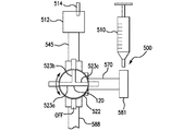
図4のクランプ及びチェックバルブ構成は、アクティブGRV測定において用いることができる図5の1若しくは複数の実施形態に見られるような、三方バルブまたは活栓に置き換えることができる。胃残量測定装置500は、経腸栄養システム100/200及び回収リザーバ512とともに用いるためのものであり、その機能は、既に上記されており、当業者によく知られている。回収リザーバ512は、ベント部514と、第1のリリーフチューブセグメント545とを有し、後者は活栓522または同様の三方バルブに接続されている。活栓522は、第2のリリーフチューブセグメント588及びバイパスチューブセグメント570にも接続されている。バイパスチューブセグメント570は、アクセスポート581にも接続されており、適切なYコネクタ、あるいは同等の結合装置または構造体であってもよい。いくつかの実施形態におけるポート581は、バイパスチューブセグメント570から逆流物を吸引することができかつ所望通り逆流物をバイパスチューブセグメント570に注入することができるような、シリンジ510または他の流体の吸引及び注入手段によりアクセス可能である。
The clamp and check valve configuration of FIG. 4 can be replaced with a three-way valve or stopcock, such as found in one or more embodiments of FIG. 5 that can be used in active GRV measurements. The gastric
活栓522は、標準的な構造のものであり、第1のリリーフチューブセグメント545、第2のリリーフチューブセグメント588、バイパスチューブセグメント570間を流れることができる逆流物及び/または他の流体のうちの任意のものを貯留するのに十分な内径を有している。当分野でよく知られているように、活栓522は、図5に示されている第1のリリーフチューブセグメント545、第2のリリーフチューブセグメント588、及びバイパスセグメント570によって画定される平面と同一の回転面にT字型流体通路523が配置された状態で構成されている(使用される三方バルブが、関連するチューブセグメント間の適切な流体連通をもたらすことができる限り、上記3つのチューブセグメントは全ての実施形態において同一平面に存在する必要はない)。T字型流体通路523の個々の通路523a、523b及び523cは、異なる流体連通モードを提供するように、様々なチューブセグメントに整合しかつ流体連通して配置される。
The
活栓522は、4つの流れ位置が可能である。第1の位置では、バイパスチューブセグメント570は遮断されており、第1のリリーフチューブセグメント545及び第2のリリーフチューブセグメント588は互いに流体連通している。第2の位置では、第1のリリーフチューブセグメント545は遮断されており、バイパスチューブセグメント570及び第2のリリーフチューブセグメント588は互いに流体連通している。第3の位置では、図5に示されているように、第2のリリーフチューブセグメント588は遮断されており、バイパスチューブセグメント570及び第1のリリーフチューブセグメント545は互いに流体連通している。最後に、第4の位置では、バイパスチューブセグメント570、第1のリリーフチューブセグメント545及び第2のリリーフチューブセグメント588は全て流体連通している。
The
GRV測定が行われる場合は、活栓522は第2の位置に戻り、シリンジ510により装置500から第2のリリーフチューブセグメント588及びバイパスチューブセグメント570を経由して流体を吸引する。このことは、GRV測定に必要な胃内容物の全てを蓄積するのに必要な回数だけ行うことができる。蓄積された流体の測定後、活栓522を第3の位置へ回すことにより、回収された流体をバイパスチューブセグメント570及び第1のリリーフチューブセグメント545を経由してリザーバ512内へ注入することができる。リザーバ512内に所望の量の回収された流体が入れられたら、活栓522を第1の位置へ回すことにより、回収された胃内容物を患者の胃に重力を用いて再導入し、流体を回収リザーバ512から第1のリリーフチューブセグメント545及び第2のリリーフチューブセグメント588を経て患者へ移動させることができる。シリンジ510上の容積表示部を用いて、患者から回収された逆流物の量を測定することができる。例えば、50mLのシリンジを用い、容積表示部を用いて逆流物を測定することによって逆流物を除去及び測定することができる。逆流物の量がシリンジ510の容量を超えている場合、逆流物が患者に再導入されるまで、逆流物を測定して容器に入れることができる(例えば、50mLシリンジが4つ、37mLシリンジが1つであれば、237mLの胃残量測定値を示すことになる)。別の実施形態例では、流体除去及び再導入装置は、シリンジ510と、容積表示部を含む測定容器とを含むことができる。シリンジ510を用いて、アクセスポート4581を通して逆流物を除去しかつ除去された逆流物を測定容器に入れることができる。その後、臨床医は、測定容器上に配置された容積表示部を用いて胃残量測定値を求めることができる。
When a GRV measurement is performed, the
追加の選択肢として、吸引された胃内容物を回収した後、アクセスポート481/581からシリンジ410/510を係脱することができる。シリンジを取り外したら、栄養チューブまたはサンプチューブの留置をさらにチェックするために、シリンジから吸引された胃内容物を数滴、pH試験紙またはpHメータに適用することができる。英国(UK)のNHS国立患者安全機関(NPSA)によれば、患者の胃内における栄養チューブの先端の位置を確認するためには「安全範囲としてpH1〜5.5」である。
As an additional option, the
回収リザーバの材料及び設計 Collection reservoir material and design
以前のシステムでは、図1、図2A〜図2C及び図3Aの回収リザーバ112、212及び312(以下、回収リザーバ112と呼ぶ)は、通常、フレキシブルな弾性プラスチック製、例えば、ポリエチレン製、エチレン酢酸ビニル(EVA)製、またはポリ塩化ビニル(PVC)製の軟質バッグであった。本明細書に開示されているいくつかの実施形態では、回収リザーバ112は、代わりに、逆流物を保持するように増加可能な容量を許容するべく、膨張性材料または弾性材料でできたものであってよい。あるいは、回収リザーバ112は、より形状保持力のある容器、例えば、ポリエチレンまたはポリプロピレンプラスチックボトルなどを具体化することができ、それによって、胃圧軽減システム110及び栄養システム100/200の移動可能性を向上させること及び他の利点を提供することができる。そのような実施形態は、そのような利点を実現するために、硬質または半硬質リザーバを用いることができる。いくつかの実施形態では、リザーバ内の液体が隔壁または隅部に粘着しないように疎水性材料を用いることができる。表面張力を低下させるために、特別なバッグ材料、または(多層バッグ薄膜材料構造における)バッグ材料の内層、またはリザーババッグの内面上の被覆材料ライニングを実装することができる。このことは、吸引された胃内容物を患者に戻すとき、または吸引物をドレインポートを通して廃棄するときに、より容易に全ての液体を排出すること、及び液体の残留物を減少させ、最小にしかつ/または排除することを可能にする。回収リザーバ112は、液体及び固体材料の侵入に対して閉鎖され、回収リザーバ112内に栄養剤などが流れ込んだり導入されたりさせないので、システムの投与容器146と容易に区別できる。
In previous systems, the
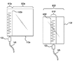
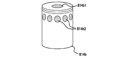
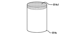
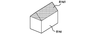
例えば、容易な測定、観察、及び改良されたモニタリングが必要とされているかまたは望ましい場合には、図6Aに示されているような、液面のモニタリング及び追跡をより容易にする特別なマーク及び/または他の表示部を備えた、単一チャンバの、またはV字形状の、または円錘台形の回収リザーバ112aを用いることができる(例えば、回収リザーバ112aは、そのようなシステムにおいて用いられる様々なチューブセグメントのように、異なる色付きlevel及び/またはカラー印刷を有することができる)。あるいは、いくつかの実施形態において、同様に図6Aに示されているような、段付き回収リザーバ構成112b及び112cを用いることができ、液面、患者の活動などの測定及びモニタリングを容易にしかつ/または向上させるために、リザーバ内の互いに異なるセクションを用いることができる。一実施形態例では、容積表示部は細かい容積表示部610であってよく、これには、回収リザーバ112上において他の表示部よりも間隔が狭い容積測定表示部が含まれる。細かい容積表示部610は、流体のより小さな容積増分(例えば、5mL及び10mL)において、より正確な容量の読みを提供する。さらに、容積表示部は粗い容積表示部620であってよく、これには、回収リザーバ112上において他の表示部よりも間隔が離れている容積測定表示部が含まれる。粗い容積表示部620は、流体のより大きな容積増分(例えば、50mL及び100mL)を測定する。別の実施形態例では、容積表示部は、不定の容積表示部630であってよく、これには、回収リザーバ112上において不定間隔の容積表示部が含まれる。細かい容積表示部610及び粗い容積表示部620は、不定間隔または等間隔の表示部を含むことができる。最後に、図6Bに見られるように、先細になっている回収リザーバ構成112dであって、リザーバの下方部分の先細になっている狭小部が、同様の容積測定値の読み易いマーク及び/または他の表示部を提供するような構成を用いることができる。多くの場合、患者から蓄積された流体はリザーバを満たさないので、回収リザーバ112a、112b、112c及び112dとともに示されているような、段付き構成、あるいは、より正確な、及び/またはより読み易い指標を有する他の特殊な構成が非常に有用であり得る。
For example, if easy measurement, observation, and improved monitoring is needed or desirable, special marks and features that make liquid level monitoring and tracking easier, such as shown in FIG. 6A A single chamber, or V-shaped, or frustum-shaped
各段付き回収リザーバ構成において、2つのチャンバは、識別可能でありかつリザーバ内に画定されている。下方チャンバ612は、リリーフチューブ145に接続されており、かつ胃圧軽減システム110が用いられている患者から逆流物を受け入れるように構成されている。リザーバ112bの下方チャンバ612bは、円筒形でありかつ、測定精度の向上を可能にするべく、より小さな容積を保持している(例えば、いくつかの実施形態では、下方チャンバ612bは、その上方チャンバ622bよりも小さな径を有する)。下方チャンバ612bの容量を小さくするほど、リザーバ112b内の液面のより正確な測定及びより容易な読みが可能になるので、看護師または他の介護者が経時的な逆流物の高さ(液面)の変化を測定するのに役立つ。リザーバ112cの円錘台形下方チャンバ612cは、同様に、そのような改良された観察及び測定モニタリングを提供する。同様に、V字形状または円錘台形リザーバ112a並びに先細になっている構成112c及び112dの下方チャンバの径をより狭くするほど、回収リザーバ実施形態112a、112c及び112dに最初に回収された物質に対して、そのようなより容易な観察及び測定モニタリングが可能になるが、リザーバの径が上端に向かって増大するにつれて、上記の観察の容易さは損なわれる。
In each stepped collection reservoir configuration, the two chambers are identifiable and defined within the reservoir. Lower chamber 612 is connected to
回収リザーバが満たされるにつれて、読み及び測定精度の重要性が低下し得る。そのような場合には、段付き回収リザーバの実施形態112b、112cの下方チャンバ612b、612cはそれぞれ、接続している圧力リリーフチューブ145よりも上方に(またはリリーフチューブ145を考慮して)、適切な量の流体、例えば約50mL、100mL、250mLまたは500mLの流体を保持するように構成することができる。同様に、この場合もやはり胃圧軽減システム110における逆流物の量に関する迅速かつ信頼できるフィードバックを看護師または他の介護者に与えるために、各回収リザーバ実施形態112b及び112cの下方チャンバ及び/または上方チャンバの全部または一部は、色付きのもの(または色分けされた測定表示部)であってよい。回収リザーバ112a及び112dにも同様に色分けを用いることができる。逆流物の1若しくは複数の閾値レベル、例えば、患者の胃の中の胃内圧が過剰である、患者に供給されている栄養剤の消化/受入速度が低い、などの兆候を検知するためのモニタリング時には、回収リザーバ112a、112b、112c、112d(総称して回収リザーバ112と呼ぶ)上の容積測定表示部(数値及び/または色の使用、あるいは他の非数値表示部であってよい)は特に有用であり得る。
As the collection reservoir is filled, the importance of reading and measurement accuracy may decrease. In such a case, the
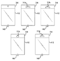
図6C及び図6Dは、例えば回収リザーバ112b及び112cの垂直に方向付けられたチャンバではなく、隔壁などによって隔てられている横方向に区別された(すなわち、隣り合った)チャンバを用いて、測定及び観察を容易にする回収リザーバの他の実施形態を示している。これらの横方向チャンバの実施形態では、第1のチャンバは第2のチャンバと隣り合っており、これら2つのチャンバは、ほぼ同じ垂直高さに位置し得る。図6Cは、最初の逆流物の観察及び測定をより容易にする第1のチャンバを含む回収リザーバの1若しくは複数の実施形態の側面図である。リザーバ112eでは、回収リザーバ112eに逆流する如何なる逆流物も、容易に読めるマークを有する第1のチャンバ612e(例えば側部チャンバ)に最初に貯留するように、第1のチャンバ612e(例えば側部チャンバ)がリリーフチューブ145に接続されている。第1のチャンバ612e(例えば側部チャンバ)が最大容量まで満たされたら、オーバーフロー隔壁632eは、逆流物がオーバーフローして第2のチャンバ622eを満たすことを許容する(632e及び632fを総称して隔壁632と呼ぶことができる)。この構成は、逆流物の容易に読める測定値を提供する一方で、回収リザーバがより小さな構成を維持することを可能にする。同様に、回収リザーバ112fは、同様の小径の第1のチャンバ612fを有し、該チャンバは、容易な読み及び必要に応じて隔壁632fを通って第2のチャンバ622f内へのオーバーフローを許容する(622e及び622fを総称して第2のチャンバ622と呼ぶことができる)。
FIGS. 6C and 6D show measurements using laterally differentiated (ie, adjacent) chambers separated by a septum or the like, for example, rather than the vertically oriented chambers of the
図6Dは、各回収リザーバ構成の幾つかの不定特性によって決まる、回収リザーバ112e、112fのうちの1つ以上の上面図を示している。(図6Cのリザーバ112e及び/または112fの上面図であり得る)図6Dの回収リザーバ640では、第2のチャンバ642は、硬質の第1のチャンバ644に結合された軟質またはフレキシブルバッグである。このことは、デュアルチャンバ構成の利点とともに、製造中及び使用前に回収リザーバ640のコンパクトでかつ容易な保存を可能にする。第1のチャンバ644は、その意図された製造、梱包及び使用に最も適した如何なる断面をも有することができる。同様に、(同様に図6Cの回収リザーバ112e及び/または112fの上面図であり得る)図6Dの回収リザーバ650において、第1のチャンバ(例えば側部チャンバ)はこの場合もやはり硬質チューブ654などであるが、この構成において第2の(より大きな)チャンバ652もまた硬質であるので、形状保持力のある構造物を提供し、これは状況次第では好ましいであろう。同様に、(この場合もやはり図6Cの回収リザーバ112e及び/または112fの上面図であり得る)図6Dの回収リザーバ660は、正方形または矩形の断面を有するチャンバ662、664を用いており、これは図6Dの回収リザーバ670も同様で、回収リザーバ670はチャンバ672、674を有している。この場合もやはり、首尾一貫した径間隔を有する第1のチャンバ構成には、均等間隔の増分または測定指標が用いられ、第1のチャンバの先細になっている径の間隔は、適切に離間された指標を必要とする。
FIG. 6D shows a top view of one or more of the
回収リザーバの他の実施形態には、図6Cの回収リザーバ112eの上面図であり得る図6Dのリザーバ680が含まれ、これは、隔壁686によって第1のチャンバ684及び第2のチャンバ682に分けられている単一硬質矩形構造を有する。最後に、図6Cの回収リザーバ112eの上面図であり得る図6Dの回収リザーバ690は、隔壁696によって第1のチャンバ694及び第2のチャンバ692に分けられた単一の硬質の卵形または円形構造を有する。
Other embodiments of the collection reservoir include the
したがって、上記の実施例から分かるように、所与の回収リザーバ構成の第1及び第2のチャンバは、所望の製造、梱包及び性能特性を提供するように、同じかまたは異なる材料及び様々な断面形状で製作することができる。同様に、回収リザーバ112b及び回収リザーバ112cの垂直方向に区別されたチャンバに関して、段付き構成の下方チャンバは硬質であり得るが、上方チャンバ(例えば、チャンバ622bまたは622c)あるいは回収リザーバの他のセクションまたは部分は、軟質プラスチック、エラストマー材料などである。
Thus, as can be seen from the above examples, the first and second chambers of a given recovery reservoir configuration can be of the same or different materials and various cross-sections to provide the desired manufacturing, packaging and performance characteristics. Can be manufactured in shape. Similarly, with respect to the vertically differentiated chambers of
回収リザーバは、過剰な胃圧が発生した場合に相当な量の逆流物を受け入れるのに十分な容量を有していなければならない。例えば、図1の胃圧軽減システム110が成人の経腸栄養に用いられるとき、回収リザーバ112は、約500mLの流体容量を有することが好ましい。回収リザーバ112は、小さな患者(例えば、小児及び新生児の患者)用には、該患者のより小さな体の大きさ及びそれに見合うより小さな胃容量に基づいて、より小さく縮小される。歴史的に、医療流体用のフレキシブル/軟質プラスチックバッグは、50mL、100mL、250mL、500mL及び1Lのサイズが標準とされていた。米国静脈経腸栄養学会(ASPEN)から複数のガイドラインが発行されており、そのうちの、2009年ガイドライン出版物では、不耐性の他の兆候の非存在下での500mL未満の胃残量には、経腸栄養剤(EN)を保持しないことが推奨されている。“Guidelines for the provision and assessment of nutrition support therapy in the adult critically ill patient: Society of Critical Care Medicine and American Society for Parenteral and Enteral Nutrition: Executive Summary” (Crit Care Med 2009 Vol. 37, No. 5)(非特許文献1)を参照されたい。必要な胃容積がより少ない新生児に対しては、より小さなバッグサイズ(例えば、250mLまたは100mL)を用いることができる。
The collection reservoir must have sufficient capacity to accept a substantial amount of reflux if excessive gastric pressure occurs. For example, when the gastric
支持スタンド130などから吊り下げられている間に回収リザーバ112が動きやすい環境では、図7Aの幾つかの例示的実施形態に見られるように、回収リザーバ112用のセルフセンタリングハンガー機能を実装することができる。図7Bに示されているように、図示されている様々なハンガー開口実施形態に重力の力(g)が作用する。一例では、ハンガータブ716に形成された三日月形の開口717aが用いられている。別の図示された実施例では、代わりに、逆V字形状の開口717bが用いられている。角丸三角形の開口717cは、三角形の頂点が丸められたそれほど細長くない孔を有するハンガータブを提供する。最後に、ノッチ付き三日月形開口717dを実装することもできる。これらの例の各々において、開口717は、重力に基づくセルフセンタリング機能を提供する。図6Aの回収リザーバ112bの一例が図7Bに示されており、ここで、回収リザーバ112bは、硬質の、径を小さくした測定チャンバである下方の第1のチャンバ612bを有し、さらに、第2の、上方チャンバ622bは、ノッチ付き三日月形開口717dを用いて吊り下げることができる軟質プラスチックなどである。さらに、様々な位置で吊るすための、簡易で、可搬性があり、かつ容易に取り付け/取り外しされる装置を得るために、回収リザーバ112を容易に移動可能にする機構(例えばカラビナクリップなど)を用いることができる。したがって、経腸栄養システム100/胃圧軽減システム110には、回収リザーバ112を支持スタンド130から中心位置に有利に吊り下げるための回収リザーバ吊下装置が備わっている。
In an environment where the
ベント部形状及び材料 Vent shape and material
以前のシステムでは、ベント部114は、ガスを回収リザーバ112から大気へ除去させるチューブ、または他の中空、中実要素であった。そのような以前のベント部114の「開放」性は、当該ベント部を用いるリザーバの使用及び多用途性を制限していた。さらに、ベント部114が回収リザーバ112の内部への開口部である場合には、システム100内で閉鎖液体系が維持されない。
In previous systems, the
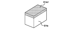
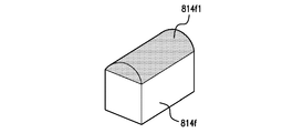
本発明の種々の実施形態は、1若しくは複数のメンブレンを含むベント部を用いて、回収リザーバからのガスの除去を可能にするが、ベント部のいくつかの実施形態を図8Aないし図8Fに示す。図8Aのベント部814aは、上部メンブレン814a1及び側部矩形メンブレン814a2を有するベント部を示している。同様に、図8Bのベント部814bは、上部及び側部メンブレンを有するが、その形状及び/または大きさが異なっており、例えば、上部メンブレン814b1及び側部楕円形メンブレン814b2を有する。さらに異なる実施形態では、図8Cのベント部814cは、他の標準的なベントチューブに取り付けられた上部メンブレン814c1を示している。最後に、断面が矩形のベントシャフトは、図8Dにおいてベント部814dの一部として「屋根」形状のメンブレン814d1を有する。ベント部814dに類似している他の構造は、ベント部領域の断面に関して、矩形または「屋根形」(例えば、図8Eに示したベント部814eのメンブレン814e1として見られるような)、半円形(例えば、図8Fに示したベント部814fのメンブレン814f1として見られるような)などであってよい(ベント部814a、814b、814c、814d、814e及び814fは総称してベント部814と呼ぶことができる)。
While various embodiments of the present invention allow for removal of gas from the collection reservoir using a vent that includes one or more membranes, several embodiments of the vent are illustrated in FIGS. 8A-8F. Show. The
1若しくは複数のメンブレンが用いられる実施形態では、そのようなメンブレンは各々、適切な範囲の材料及び構成(例えば、ゴア・アンド・トリニティ・テクノロジー・グループ(TTG)の製品である材料から製造された疎水性及び/または疎油性メンブレン)から選択することができる。例えば、メンブレン材料は、不織ナイロン支持体上にキャストされたアクリルコポリマーメンブレンであってよい。メンブレンは、疎油性及び/または疎水性に関して、所望の性能に合わせて処理することができる。 In embodiments where one or more membranes are used, each such membrane was manufactured from a suitable range of materials and configurations (eg, materials that are products of the Gore and Trinity Technology Group (TTG)). Hydrophobic and / or oleophobic membranes). For example, the membrane material may be an acrylic copolymer membrane cast on a nonwoven nylon support. The membrane can be treated to the desired performance with respect to oleophobicity and / or hydrophobicity.
例えば、通気度(すなわち、空気透過性の尺度であり、通常はガーレー値によって測定される)、液体表面張力(表面と空気の界面において表面下の分子が及ぼす力)、固体表面自由エネルギー(表面と空気の界面において表面下の分子が及ぼす力)、メンブレンの含浸特性(メンブレンの孔を流体で満たす)などが、メンブレンの選択に重要な要素であり得る。回収リザーバ内容物がベント部に頻繁に接触する可能性が高い環境において回収リザーバが用いられる場合には、その効率を低下させる「濡れ」に耐えるベント部実施形態が用いられる。メンブレンはまた、所望の作動特性を与えるように、適切な形状、表面積及び位置を有するものであってよい。例えば、図8Aないし図8Fに示されているように、ベント部814a、814b、814d、814e及び814f(及び恐らくは他の実施形態)は、バックパックまたは回収リザーバがシフトし得るような他の環境で用いられるとき、及び/または経腸栄養システム及び関連する胃圧軽減システム110が使用中である間に他の材料がベント部と接触しそうなときには、各ベント部の完全な覆いを作り出す可能性が低い。
For example, air permeability (ie, a measure of air permeability, usually measured by Gurley values), liquid surface tension (force exerted by subsurface molecules at the surface-air interface), solid surface free energy (surface The forces exerted by molecules below the surface at the air / air interface), the impregnation properties of the membrane (filling the pores of the membrane with fluid), etc. can be important factors in membrane selection. If the collection reservoir is used in an environment where the collection reservoir contents are likely to come into frequent contact with the vent section, a vent section embodiment that withstands “wetting” that reduces its efficiency is used. The membrane may also have an appropriate shape, surface area and location to provide the desired operating characteristics. For example, as shown in FIGS. 8A-8F, vents 814a, 814b, 814d, 814e and 814f (and possibly other embodiments) may be used in other environments where the backpack or collection reservoir may shift. And / or when other materials are likely to come into contact with the vents while the enteral feeding system and associated gastric
ドレインポートとバッグのディスコネクト Drain port and bag disconnect
経腸栄養システムを「閉鎖系」として維持することにより、システム、内容物、及び最終的に患者の、予期せぬ汚染を防止することが望ましい。さらに、「閉鎖系」は、経腸送達システムにつきものである胃の体液、栄養剤及び薬剤への暴露から、臨床医、介護者、及び/または患者を保護する。本明細書に開示されている実施形態は、そのようなシステムにおいて、(例えば、回収リザーバ、投与容器及び/またはリリーフセグメントのための)「オンデマンドのみの」ドレインポート、クイックディスコネクト機能、及び/または他のアクセス装置を実装しており、詳細については後述する。 By maintaining the enteral nutrition system as a “closed system”, it is desirable to prevent unexpected contamination of the system, contents, and ultimately the patient. In addition, the “closed system” protects the clinician, caregiver, and / or patient from exposure to gastric fluids, nutrients and drugs associated with enteral delivery systems. Embodiments disclosed herein may include, in such systems, “on demand only” drain ports (eg, for collection reservoirs, dosing containers and / or relief segments), quick disconnect functionality, and Other access devices are mounted and details will be described later.
回収リザーバの交換を容易にするために、及び/または回収リザーバ912を空にするための代替手段として、例えば、本明細書において、及び先行技術に関して、定義されかつ説明されているような、GRV手順などの一部として、図9Aに見られるようなクイックリリースコネクタ装置932を、経腸栄養システム900におけるリザーバ912とリリーフチューブ945との間の接続において提供することができる。コネクタ装置932は、以下で詳細に説明する「リザーバの上昇」実施例において見られるような、回収された内容物を例えばGRV回収プロセスにより除去するため、または最初の胃内容物の排出機能におけるシステム900の使用を促進するために用いることができるようなドレインポート942を含むかまたは付加することができる。ドレインポート942が実装されている場合には、(例えば、ネジ式コネクタ、ENPlus経腸栄養接続システム(その一例が図9Bにコネクタ952として示されている)、または経腸及び/または胃の減圧/抜圧用途に適した同様の密閉コネクタ構造を用いて)効果的に密閉しなければならない。
To facilitate replacement of the recovery reservoir and / or as an alternative to emptying the
回収リザーバ912へのリリーフチューブ945の抜き差しを容易にすることに加えて、クイックリリースコネクタポートまたは他の同様の装置を用いて回収リザーバ912の内容物を経腸投与容器に移し替えることを容易にするために、システム900の一部である経腸投与容器の上端にクイックリリースコネクタ装置932を複製することもできる。いくつかの実施形態では、回収リザーバ912及び経腸投与容器がともに使用されている間に移し替えを行うことができ、あるいは一方または両方を操作から切り離し、当該切り離した状態で移し替えを行うことができる。
In addition to facilitating removal and insertion of the
硬質リザーバは、経腸栄養システムの移動可能性を向上させることもできる。そのような実施形態では、リザーバは、残存物などの容易な除去及び廃棄を可能にするように、図9Aに示すようなドレインポート942を含むことができる。リザーバの交換を促進するために(またはリザーバを空にするための代替手段として)、任意の関連するチューブへのリザーバの接続部において、図9Aに見られるようなクイックリリースコネクタ装置932を提供することができる。さらに、簡易で、可搬性があり、かつ容易に取り付け/取り外しされる装置を得るために、容易に移動可能にする機構(例えばカラビナクリップなど)を用いることができる。さらに、コネクタ装置932は、胃内残存物の容易な除去、サンプリングまたは廃棄を可能にするためのドレインを含むことができる。
A rigid reservoir can also improve the mobility of the enteral feeding system. In such embodiments, the reservoir can include a
配置時注意喚起部(プレースメントリマインダ) Placement reminder (placement reminder)
いくつかの実施形態では、例えば図10に示すように、配置時注意喚起部1011(例えば、注意喚起タブ、ラベル、タグ、フラグなどの形態をとる)を、コネクタ120に挿入されるリリーフチューブ145、投与チューブ142及び/または流体送達チューブ144のうちの1つ以上より前に、Yコネクタ120に取り付けることができる。この配置時注意喚起部1011は、ユーザが配置時注意喚起部1011を考慮し、胃圧軽減システム110の使用を開始する前に患者の胃の高さに対するYコネクタ120の高さをチェックせずにはいられないようにする形で、Yコネクタ120または他のシステム構成部分に取り付けられたタグ、ラベルまたはテープの形態をとることができる。配置時注意喚起部1011は、Yコネクタ120またはチューブセグメントのうちの1つに通せるように、孔を有することができる。投与チューブ142、流体送達チューブ144、リリーフチューブ145などのチューブセグメントのうちの1つの上に、及び/または装置の1若しくは複数の構成部分上の他の場所に、同様の情報を含むメッセージを印刷したり、エンボス加工したりすることなどもできる。図10に示されている他の実施形態では、配置時注意喚起部1011が取り付けられているプラグ1007をYコネクタ120の少なくとも1つの開口アームに挿入することができるので、看護師または他のユーザはプラグ1007を外す必要があり、したがって、最初にプラグ1007が除去されるまでチューブセグメントへのYコネクタ120の接続を防止する。プラグ1007は、胃圧軽減システム110を使用する前にYコネクタ120を患者の胃またはそれよりも下に配置しなければならないという注意喚起が印刷された小片またはタブの形状をとるものであってもよい。別の代替形態は、Yコネクタ120の1若しくは複数のアームに対して、または該アームの表面上に取り付けることができる配置時注意喚起部1011が取り付けられているキャップ1009であり、この場合もやはり、Yコネクタ120の使用に先立ち配置時注意喚起部1011の除去が必要とされる。このようにして、配置時注意喚起部1011は、看護師または他のユーザがYコネクタ120を患者の胃の高さまたはそれよりも下に配置しかつ維持することを忘れる可能性を低減させる。ラベル自体は、紙製、フラッシュスパン(flashspun)高密度ポリエチレン繊維から製造された材料製、不織スパンボンドオレフィン繊維から製造された材料製、プラスチック製、または任意の他の適切な材料製であってよく、注意書きの効果をさらに高めるために色鮮やかにすることができる。したがって、経腸栄養システム100/胃圧軽減システム110には、患者の胃の高さに対するYコネクタ120の適切な使用高さに関して臨床医に有利に知らせるための配置時注意喚起具が備わっている。
In some embodiments, as shown, for example, in FIG. 10, a placement reminder 1011 (eg, in the form of a reminder tab, label, tag, flag, etc.) is inserted into the
流れ表示部 Flow display section
逆流物の高さ(液面)の観察及び追跡することを助けるために、胃圧軽減システム110のいくつかの実施形態は、二方向流れ表示部1100が印刷されているか、エンボス加工されているか、または別な方法で見ることができるような、1若しくは複数のチューブセグメントを含む。そのような二方向流れ表示部1100は、矢印などを含むことができ、その例示的実施形態は図11に見られる。そのような二方向流れ表示部1100が繰り返しまたは他のパターン化された方法で提供される場合、個人は、そのようなチューブセグメント内の液面の動きを追跡したり、認識したりなどすることができる。いくつかの実施形態では、そのような二方向流れ表示部1100をチューブの色付きセグメントまたは他の強調手段と併用することにより、チューブ内の変化する液面の読み及び認識を容易にすることができる。例えば、図1の胃圧軽減システム110及び経腸栄養システム100では、リリーフチューブセグメント145及び流体送達チューブセグメント144はともに、そのような二方向流れ表示部1100を有することができる(場合によっては、容積表示部などに加えて)。
To assist in observing and tracking the height (liquid level) of the reflux, some embodiments of the gastric
マルチチャンバリザーバ112を用いる実施形態または他のリザーバ実施形態では、看護師または介護者に特定の栄養剤/逆流容積レベルを警告するために閾値マークを提供することができる。例えば、リザーバ112上の所与のマーク(例えば色の付いた表示部を含む)は、栄養システム内の閉塞の可能性や、栄養供給不耐性(例えば、胃の運動性障害からの、嘔吐、吐き気、過剰な流体)の存在、胃排出遅延または胃腸閉塞を警告することができる。
In embodiments using
リザーバの徐々の上昇 Gradual rise of reservoir
経腸栄養に関する1若しくは複数の方法実施形態を図12A〜図12Dに示す。Yコネクタ1220に接続されている投与チューブセグメント1242とともにクランプ機構1222などを用いて栄養剤の流れが阻止される。リザーバ1212は、一般的な点滴懸架スタンド1290の最も低い高さ付近に初期位置を有する。患者の胃内容物が栄養チューブ1288を経て回収リザーバ1212に回収された後、Yコネクタ1220及びリリーフチューブ1245、投与容器1246からの経腸栄養剤の流出が開始され、その後、回収リザーバ1212の徐々の上昇が開始する。そのような方法では、図12A〜図12Dに示したように、経腸栄養システム1200の使用は、ノミナル操作位置よりも十分に下の位置、例えば床1295付近かつ患者1285の高さよりも下に吊り下げられている回収リザーバ1212から始める。回収リザーバ1212を図12Aに示した開始位置から図12Bに示した第1の中間位置へ上昇させるときに、患者の胃内容物の最初の排出を提供するように、回収リザーバ1212を段階的進度で(例えば、1フィート、または他の選択された増分で)上昇させる。回収リザーバ1212を図12Bに示した第1の中間位置から図12Cに示した第2の中間位置へ上昇させるときに、患者の胃内容物の追加の排出が生じる。同様に、回収リザーバ1212を図12Cに示した第2の中間位置から図12Dに示したノミナル位置へ上昇させるときに、患者の胃内容物の追加の排出が生じる。経腸栄養が進行するにつれて回収リザーバが開始位置からノミナル位置へ段階的進度で持ち上げられるので、最初に回収された胃内容物の一部または全部の徐々の再導入が生じる。投与容器1246から投与チューブ1242を経て栄養剤を流し始める前に、GRV評価を行うことができる。
One or more method embodiments for enteral nutrition are shown in FIGS. 12A-12D. The feeding of the nutrient solution is prevented by using a
回収リザーバ1212が、図12Dに示したノミナル位置に来るまで、各ステップ内で完全な、正常な栄養剤の流れ及び胃逆流物の平衡が達成される。平衡は、リリーフチューブ1245内の液面の安定性を見ることによって認識することができ、液面の安定性は、経腸栄養システム1200が患者に栄養剤を供給する準備ができていることを示す。例えば、液面が所定の時間(例えば1分間)にわたって同じままである場合には、液面は安定している(すなわち、変化しない)と判断される。例えば、臨床医は、液面を見て、その後、所定の時間(例えば1分間)の後に液面の安定性を再チェックすることにより、平衡に達したことを判定することができる(すなわち、流体は、再チェック後に実質的に同じ高さにある)。先ず、臨床医は、図12Aに示した開始位置に回収リザーバ1212を配置することにより、胃内容物が患者の胃から流出して回収リザーバ1212内に排出されるようにする。その後、臨床医は、回収された胃内容物を患者の胃内に再導入したいであろう。これを行うために、臨床医は、回収リザーバ1212を開始位置から第1の中間位置へ上昇させることにより、回収リザーバ1212から患者の胃に戻る(すなわち、図12Aから図12Bへの)胃内容物の最初の排出をもたらすことができる。第1の中間位置において胃逆流物の平衡が達成されたことが判定されたら、臨床医は、回収リザーバ1212を第1の中間位置から第2の中間位置へ(すなわち、図12Bから図12Cへ)上昇させることができる。その後、第2の中間位置において胃逆流物の平衡が達成されたことを判定した後に、臨床医は、回収リザーバ1212を第2の中間位置からノミナル位置へ(すなわち、図12Cから図12Dへ)上昇させることができる。一実施形態例では、回収リザーバ1212を段階的進度で上昇させる際に、異なる数の中間位置(例えば、4つないし6つの中間位置)を用いることができる。このプロセスは、いくつかの実施形態では、回収リザーバ1212よりも上方の滑車型装置1275を用いて達成することができる。他の実施形態では、回収リザーバ1212は、回収リザーバ1212を上昇させるにつれて徐々にスタンド1290にリンクさせることができるリンク点を有する紐状体1292または他の線状体を用いて吊り下げることができる。上記の説明から分かるように、患者が経腸栄養(すなわち消化)に耐え始めるにつれて、回収リザーバ1212が持ち上げられるまで、回収リザーバ1212が投与容器または他の栄養源ないしはそれ以上の標準的な位置で吊られている状態で患者が経腸栄養システム1200の操作に耐えることができるまで、回収リザーバ1212を上昇させて、栄養供給速度を増加させることができる。
Full recovery nutrient balance and gastric reflux balance are achieved within each step until the
この方法は、患者の状態及び状況が必要とする場合には良好な代替案であり、その利点は、臨床医が最初に胃の手術領域の圧力を取り除き、再び、患者の特定の臨床状態に基づいて、患者を徐々に楽にして患者が耐えることができる最大限の経腸栄養に戻すことができることである。 This method is a good alternative if the patient's condition and situation require it, and its advantage is that the clinician first removes the pressure in the surgical area of the stomach and returns to the patient's specific clinical condition. On the basis, it is possible to gradually ease the patient back to the maximum enteral nutrition that the patient can tolerate.
本明細書に記載の主題の種々の態様は、単独で、または本明細書に記載の他の態様のうちの任意の1つ以上と組み合わせて有用であろう。前述の説明に限定することなしに、本発明の例示的態様において、胃圧軽減システムは、投与チューブに接続された投与容器、リリーフチューブ、投与チューブ及びリリーフチューブにそれぞれ流体連通している送達チューブ、多方向コネクタ、回収リザーバ、及び流量調節器を含む。多方向コネクタは、第1のアーム、第2のアーム及び第3のアームを有している。さらに、第1のアームはリリーフチューブに接続され、第2のアームは送達チューブに接続され、第3のアームは投与チューブに接続されている。回収リザーバは、リリーフチューブに流体連通している。さらに、回収リザーバは、ガスを両方向に通過させるように構成されたベント部を含み、かつ回収リザーバは、患者の胃からリリーフチューブを経て逆流流体を回収するように構成されており、回収リザーバは、患者の胃から受け入れた逆流流体の容積を表すように構成された容積表示部を含む。流量調節器は、リリーフチューブ内の流量を調節するように適合されている。 Various aspects of the subject matter described herein may be useful alone or in combination with any one or more of the other aspects described herein. Without limiting to the foregoing description, in an exemplary embodiment of the invention, the gastric pressure relief system includes a dosing container connected to the dosing tube, a relief tube, a dosing tube and a delivery tube each in fluid communication with the dosing tube. A multi-directional connector, a collection reservoir, and a flow regulator. The multidirectional connector has a first arm, a second arm, and a third arm. Further, the first arm is connected to the relief tube, the second arm is connected to the delivery tube, and the third arm is connected to the dosing tube. The collection reservoir is in fluid communication with the relief tube. In addition, the collection reservoir includes a vent configured to pass gas in both directions, and the collection reservoir is configured to collect backflow fluid from the patient's stomach via a relief tube, A volume indicator configured to represent the volume of reflux fluid received from the patient's stomach. The flow regulator is adapted to regulate the flow rate in the relief tube.
前述の態様と組み合わせて用いることができる本発明の別の例示的態様によれば、多方向コネクタはYコネクタである。 According to another exemplary aspect of the present invention that can be used in combination with the foregoing aspects, the multidirectional connector is a Y connector.
前述の態様と組み合わせて用いることができる本発明の別の例示的態様によれば、流量調節器は、リリーフチューブを通る流体の流れを選択的かつ調節可能に制限するように構成されている。 According to another exemplary aspect of the present invention that can be used in combination with the foregoing aspects, the flow regulator is configured to selectively and adjustably restrict the flow of fluid through the relief tube.
前述の態様のうちの任意の1つ以上と組み合わせて用いることができる本発明の別の例示的態様によれば、流量調節器は、手動または自動のいずれかで制御される。 According to another exemplary aspect of the present invention that can be used in combination with any one or more of the foregoing aspects, the flow regulator is controlled either manually or automatically.
前述の態様のうちの任意の1つ以上と組み合わせて用いることができる本発明の別の例示的態様によれば、流量調節器はローラークランプである。 According to another exemplary aspect of the present invention that can be used in combination with any one or more of the foregoing aspects, the flow regulator is a roller clamp.
前述の態様のうちの任意の1つ以上と組み合わせて用いることができる本発明の別の例示的態様によれば、胃圧軽減システムは、回収リザーバに結合された検知器をさらに含む。検知器は、回収リザーバの1若しくは複数の特性を検知するように構成されている。流量調節器は、多方向コネクタと回収リザーバとの間の流体の流れを制御するために検知器に結合されており、流量調節器は、リリーフチューブを通る流体の流れを選択的にかつ調節可能に制限するように構成されている。 According to another exemplary aspect of the invention that can be used in combination with any one or more of the foregoing aspects, the gastric pressure relief system further includes a detector coupled to the collection reservoir. The detector is configured to detect one or more characteristics of the collection reservoir. A flow regulator is coupled to the detector to control fluid flow between the multidirectional connector and the collection reservoir, and the flow regulator can selectively and regulate the fluid flow through the relief tube. It is configured to be limited to.
前述の態様のうちの任意の1つ以上と組み合わせて用いることができる本発明の別の例示的態様によれば、検知器は、吊下げ秤または重量ロードセルのいずれかを含む。流量調節器は、検知器と通信するデジタルコントローラをさらに含む。流量調節器は、リリーフチューブに圧力を印加するように構成された調節可能なクランプを含み、リリーフチューブに印加される圧力の量は、検知器からの測定データに基づく。 According to another exemplary aspect of the invention that can be used in combination with any one or more of the foregoing aspects, the detector includes either a suspended scale or a weight load cell. The flow regulator further includes a digital controller in communication with the detector. The flow regulator includes an adjustable clamp configured to apply pressure to the relief tube, and the amount of pressure applied to the relief tube is based on measured data from the detector.
前述の態様のうちの任意の1つ以上と組み合わせて用いることができる本発明の別の例示的態様によれば、胃圧軽減システムとともに用いるように構成された位置決め装置は、投与容器と送達チューブとの間に介装され、位置決め装置は、投与容器に接続された投与チューブを有し、位置決め装置は、リリーフチューブ、多方向コネクタ、回収リザーバ、及びクリップを含む。リリーフチューブは、投与チューブ及び送達チューブに流体連通している。多方向コネクタは、第1のアーム、第2のアーム及び第3のアームを有している。第1のアームはリリーフチューブに接続され、第2のアームは送達チューブに接続され、第3のアームは投与チューブに接続されている。回収リザーバは、リリーフチューブに流体連通している。さらに、回収リザーバは、ガスを両方向に通過させるように構成されたベント部を含み、かつ回収リザーバは、患者の胃からリリーフチューブを経て逆流流体を回収するように構成されており、回収リザーバは、患者の胃から受け入れた逆流流体の容積を表すように構成された容積表示部を含む。クリップは、多方向コネクタを患者の胃の高さまたはそれよりも下の適所に維持するように構成されている。 In accordance with another exemplary aspect of the present invention that can be used in combination with any one or more of the foregoing aspects, a positioning device configured for use with a gastric pressure relief system comprises a dosing container and a delivery tube. The positioning device includes a dosing tube connected to the dosing container, the positioning device including a relief tube, a multi-directional connector, a collection reservoir, and a clip. The relief tube is in fluid communication with the administration tube and the delivery tube. The multidirectional connector has a first arm, a second arm, and a third arm. The first arm is connected to the relief tube, the second arm is connected to the delivery tube, and the third arm is connected to the dosing tube. The collection reservoir is in fluid communication with the relief tube. In addition, the collection reservoir includes a vent configured to pass gas in both directions, and the collection reservoir is configured to collect backflow fluid from the patient's stomach via a relief tube, A volume indicator configured to represent the volume of reflux fluid received from the patient's stomach. The clip is configured to maintain the multidirectional connector in place at or below the level of the patient's stomach.
前述の態様のうちの任意の1つ以上と組み合わせて用いることができる本発明の別の例示的態様によれば、位置決め装置は、多方向コネクタに取り付けられており、かつ多方向コネクタの配置を患者の胃の高さまたはそれよりも下の適所に維持するのを助けるように構成されている重りをさらに含む。 According to another exemplary aspect of the present invention that can be used in combination with any one or more of the foregoing aspects, the positioning device is attached to a multidirectional connector and the arrangement of the multidirectional connector is It further includes a weight configured to help maintain the patient in position at or below the stomach level.
前述の態様のうちの任意の1つ以上と組み合わせて用いることができる本発明の別の例示的態様によれば、多方向コネクタは、多方向コネクタの配置を患者の胃の高さまたはそれよりも下の適所に維持するのを助けるのに十分な重量を有する第1の材料で構成されている。 In accordance with another exemplary aspect of the present invention that can be used in combination with any one or more of the foregoing aspects, the multi-directional connector can be positioned at or above the stomach height of the patient. Is composed of a first material having a weight sufficient to help maintain it in place.
前述の態様のうちの任意の1つ以上と組み合わせて用いることができる本発明の別の例示的態様によれば、クリップは衣類用クリップである。 According to another exemplary aspect of the present invention that can be used in combination with any one or more of the foregoing aspects, the clip is a garment clip.
前述の態様のうちの任意の1つ以上と組み合わせて用いることができる本発明の別の例示的態様によれば、多方向コネクタはYコネクタである。 According to another exemplary aspect of the invention that can be used in combination with any one or more of the foregoing aspects, the multidirectional connector is a Y connector.
前述の態様のうちの任意の1つ以上と組み合わせて用いることができる本発明の別の例示的態様によれば、胃圧軽減システムは、投与容器、リリーフチューブ、送達チューブ、多方向コネクタ、回収リザーバ、及びチェックバルブを含む。投与容器は、投与チューブに接続されている。送達チューブは、投与チューブ及びリリーフチューブにそれぞれ流体連通している。多方向コネクタは、第1のアーム、第2のアーム及び第3のアームを有している。さらに、第1のアームはリリーフチューブに接続され、第2のアームは送達チューブに接続され、第3のアームは投与チューブに接続されている。回収リザーバは、リリーフチューブに流体連通している。回収リザーバは、ガスを両方向に通過させるように構成されたベント部を含み、かつ回収リザーバは、患者の胃からリリーフチューブを経て逆流流体を回収するように構成されている。チェックバルブは、投与チューブからリリーフチューブまたは送達チューブのいずれかに一方向に流れを許容するように構成されている。 According to another exemplary aspect of the present invention that can be used in combination with any one or more of the foregoing aspects, the gastric pressure relief system comprises a dosing container, a relief tube, a delivery tube, a multi-directional connector, a retrieval. Includes a reservoir and a check valve. The administration container is connected to the administration tube. The delivery tube is in fluid communication with the administration tube and the relief tube, respectively. The multidirectional connector has a first arm, a second arm, and a third arm. Further, the first arm is connected to the relief tube, the second arm is connected to the delivery tube, and the third arm is connected to the dosing tube. The collection reservoir is in fluid communication with the relief tube. The collection reservoir includes a vent configured to allow gas to pass in both directions, and the collection reservoir is configured to collect a backflow fluid from the patient's stomach via a relief tube. The check valve is configured to allow flow in one direction from the administration tube to either the relief tube or the delivery tube.
前述の態様のうちの任意の1つ以上と組み合わせて用いることができる本発明の別の例示的態様によれば、チェックバルブは、多方向コネクタの第3のアーム内に配置されている内部バルブである。 In accordance with another exemplary aspect of the present invention that can be used in combination with any one or more of the foregoing aspects, the check valve is an internal valve disposed within the third arm of the multi-directional connector. It is.
前述の態様のうちの任意の1つ以上と組み合わせて用いることができる本発明の別の例示的態様によれば、チェックバルブは、多方向コネクタと投与チューブとの間に介装されている。 According to another exemplary aspect of the invention that can be used in combination with any one or more of the foregoing aspects, a check valve is interposed between the multi-directional connector and the dosing tube.
前述の態様のうちの任意の1つ以上と組み合わせて用いることができる本発明の別の例示的態様によれば、回収リザーバは、患者の胃から受け入れた逆流流体の容積を表すように構成された容積表示部を含む。 According to another exemplary aspect of the present invention that can be used in combination with any one or more of the foregoing aspects, the recovery reservoir is configured to represent the volume of reflux fluid received from the patient's stomach. Including a volume display.
前述の態様のうちの任意の1つ以上と組み合わせて用いることができる本発明の別の例示的態様によれば、胃圧軽減システムは、投与容器、リリーフチューブ、送達チューブ、多方向コネクタ、回収リザーバ、及び胃残量測定装置を含む。投与容器は、投与チューブに接続されている。送達チューブは、投与チューブ及びリリーフチューブにそれぞれ流体連通している。多方向コネクタは、第1のアーム、第2のアーム及び第3のアームを有している。さらに、第1のアームはリリーフチューブに接続され、第2のアームは送達チューブに接続され、第3のアームは投与チューブに接続されている。回収リザーバは、リリーフチューブに流体連通している。回収リザーバは、ガスを両方向に通過させるように構成されたベント部を含み、かつ回収リザーバは、患者の胃からリリーフチューブを経て逆流流体を回収するように構成されている。胃残量測定装置は、回収リザーバと多方向コネクタとの間においてリリーフチューブに相互接続されている。 According to another exemplary aspect of the present invention that can be used in combination with any one or more of the foregoing aspects, the gastric pressure relief system comprises a dosing container, a relief tube, a delivery tube, a multi-directional connector, a retrieval. A reservoir, and a gastric residue measuring device. The administration container is connected to the administration tube. The delivery tube is in fluid communication with the administration tube and the relief tube, respectively. The multidirectional connector has a first arm, a second arm, and a third arm. Further, the first arm is connected to the relief tube, the second arm is connected to the delivery tube, and the third arm is connected to the dosing tube. The collection reservoir is in fluid communication with the relief tube. The collection reservoir includes a vent configured to allow gas to pass in both directions, and the collection reservoir is configured to collect a backflow fluid from the patient's stomach via a relief tube. The gastric residue measuring device is interconnected to the relief tube between the collection reservoir and the multidirectional connector.
前述の態様のうちの任意の1つ以上と組み合わせて用いることができる本発明の別の例示的態様によれば、胃残量測定装置は、第2のリリーフチューブセグメント及び第1のバイパスチューブセグメントにそれぞれ流体連通している第1のリリーフチューブセグメント、第1の多方向コネクタ、第2のリリーフチューブセグメント及び第2のバイパスチューブセグメントにそれぞれ流体連通している第3のリリーフチューブセグメント、第2の多方向コネクタ、レギュレータ、アクセスポート、第1のチェックバルブ、及び第2のチェックバルブを含む。第1のバイパスチューブセグメントは、第1の端部及び第2の端部を有している。第1のリリーフチューブセグメントは、第1の端部と、リザーバに接続された第2の端部とを有し、第2のリリーフチューブセグメントは、第1の端部及び第2の端部を有している。多方向コネクタは、第1のアーム、第2のアーム及び第3のアームを有している。第2のリリーフチューブセグメントの第1の端部は、第1のアームに接続されている。第1のバイパスチューブセグメントの第1の端部は第2のアームに接続され、第1のリリーフチューブセグメントの第1の端部は第3のアームに接続されている。第3のリリーフチューブセグメントは、多方向コネクタの第1のアームに接続された第1の端部と、第2の端部とを有し、第2のバイパスチューブセグメントは、第1の端部と、第2の端部とを有する。第2の多方向コネクタは、第3のアーム、第4のアーム及び第5のアームを有する。第2のリリーフチューブセグメントの第2の端部は、第4のアームに接続されている。第2のバイパスチューブセグメントの第2の端部は第5のアームに接続され、第3のリリーフチューブセグメントの第2の端部は第6のアームに接続されている。レギュレータは、第2のリリーフチューブセグメントを通過する流れを制御するように適合された第2のリリーフチューブセグメントに接続されている。アクセスポートは、第1のバイパスチューブセグメント及び第2のバイパスチューブセグメントにそれぞれ流体連通している。アクセスポートは、第1のポート、第2のポート及び第3のポートを有する。第1のバイパスチューブセグメントの第2の端部は第1のポートに接続されており、第2のバイパスチューブセグメントの第1の端部は第2のポートに接続されており、第3のポートは、容積表示部を有する流体除去及び再導入装置による逆流物の除去のために構成されている。第1のチェックバルブは、アクセスポートからリザーバへの流体の流れを一方向に制限するように適合された第1のバイパスチューブセグメント内に配置されている。第2のチェックバルブは、第3のリリーフチューブセグメントからアクセスポートへの流体の流れを一方向に制限するように適合された第2のバイパスチューブセグメント内に配置されている。 According to another exemplary aspect of the present invention that can be used in combination with any one or more of the foregoing aspects, the gastric residue measuring device comprises a second relief tube segment and a first bypass tube segment. A third relief tube segment in fluid communication with each of a first relief tube segment, a first multi-directional connector, a second relief tube segment, and a second bypass tube segment, each in fluid communication with the second relief tube segment; Multi-directional connector, regulator, access port, first check valve, and second check valve. The first bypass tube segment has a first end and a second end. The first relief tube segment has a first end and a second end connected to the reservoir, and the second relief tube segment has a first end and a second end. Have. The multidirectional connector has a first arm, a second arm, and a third arm. The first end of the second relief tube segment is connected to the first arm. The first end of the first bypass tube segment is connected to the second arm, and the first end of the first relief tube segment is connected to the third arm. The third relief tube segment has a first end connected to the first arm of the multi-directional connector and a second end, and the second bypass tube segment is a first end. And a second end. The second multidirectional connector has a third arm, a fourth arm, and a fifth arm. The second end of the second relief tube segment is connected to the fourth arm. The second end of the second bypass tube segment is connected to the fifth arm, and the second end of the third relief tube segment is connected to the sixth arm. The regulator is connected to a second relief tube segment that is adapted to control flow through the second relief tube segment. The access port is in fluid communication with the first bypass tube segment and the second bypass tube segment, respectively. The access port has a first port, a second port, and a third port. The second end of the first bypass tube segment is connected to the first port, the first end of the second bypass tube segment is connected to the second port, and the third port Is configured for removal of the backflow by a fluid removal and reintroduction device having a volume indicator. The first check valve is disposed within a first bypass tube segment that is adapted to restrict fluid flow from the access port to the reservoir in one direction. The second check valve is disposed in a second bypass tube segment that is adapted to restrict fluid flow from the third relief tube segment to the access port in one direction.
前述の態様のうちの任意の1つ以上と組み合わせて用いることができる本発明の別の例示的態様によれば、胃残量測定装置は、第1のリリーフチューブセグメント、第2のリリーフチューブセグメント、バイパスチューブセグメント、多方向(マルチウェイ)バルブ、及びアクセスポートを含む。第1のリリーフチューブセグメントは、リザーバに接続された第1の端部と、第2の端部とを有している。バイパスチューブセグメントは、第1のポート、第2のポート及び第3のポートを有する。第1のリリーフチューブセグメントの第2の端部は、多方向バルブの第1のポートに接続されている。第2のリリーフチューブセグメントは多方向バルブの第2のポートに接続され、バイパスチューブセグメントの第2の端部は多方向バルブの第3のポートに接続されている。多方向バルブは、常時少なくとも2つのチューブセグメントを通る流体の流れを選択的に許容するように構成されている。アクセスポートは、第1のポート及び第2のポートを有する。バイパスチューブセグメントの第1の端部はアクセスポートの第1のポートに接続され、第2のポートは、容積表示部を有する流体除去及び再導入装置による逆流物の除去のために構成されている。 According to another exemplary aspect of the present invention that can be used in combination with any one or more of the foregoing aspects, the gastric residue measuring device comprises a first relief tube segment, a second relief tube segment. , Bypass tube segments, multi-way valves, and access ports. The first relief tube segment has a first end connected to the reservoir and a second end. The bypass tube segment has a first port, a second port, and a third port. The second end of the first relief tube segment is connected to the first port of the multidirectional valve. The second relief tube segment is connected to the second port of the multi-way valve, and the second end of the bypass tube segment is connected to the third port of the multi-way valve. The multidirectional valve is configured to selectively allow fluid flow through at least two tube segments at all times. The access port has a first port and a second port. The first end of the bypass tube segment is connected to the first port of the access port, and the second port is configured for fluid removal having a volume indicator and removal of the reflux by the reintroduction device. .
前述の態様のうちの任意の1つ以上と組み合わせて用いることができる本発明の別の例示的態様によれば、配置時注意喚起具は、胃圧軽減システムとともに用いるように構成されており、配置時注意喚起具は、送達チューブの遠位端と投与チューブに接続された投与容器との間に介装されるようにも構成されており、配置時注意喚起具は、多方向コネクタ、リリーフチューブ、回収リザーバ、及び配置時注意喚起部を含む。多方向コネクタは、投与チューブを流体送達チューブに接続するように構成されている。リリーフチューブは、多方向コネクタに接続されている。回収リザーバは、リリーフチューブに接続されている。さらに、回収リザーバは、患者の胃からリリーフチューブを経て逆流流体を回収するように構成されている。配置時注意喚起部は、胃圧軽減システムに取り付けられるように構成されており、かつ胃圧軽減システムの使用にあたっての患者の胃の高さに対するコネクタの適切な使用高さに関する情報を含んでいる。 According to another exemplary aspect of the present invention that can be used in combination with any one or more of the foregoing aspects, the placement reminder is configured for use with a gastric pressure relief system, The placement reminder is also configured to be interposed between the distal end of the delivery tube and a dose container connected to the dose tube, the placement reminder comprising a multi-directional connector, relief Includes tube, collection reservoir, and placement alert. The multidirectional connector is configured to connect the administration tube to the fluid delivery tube. The relief tube is connected to the multidirectional connector. The collection reservoir is connected to the relief tube. Further, the collection reservoir is configured to collect the backflow fluid from the patient's stomach via a relief tube. The placement reminder is configured to be attached to a gastric pressure relief system and includes information regarding the proper usage height of the connector relative to the height of the patient's stomach when using the gastric pressure relief system. .
前述の態様のうちの任意の1つ以上と組み合わせて用いることができる本発明の別の例示的態様によれば、送達チューブは、流体送達チューブ及び栄養チューブを含む。流体送達チューブは、チューブコネクタによって栄養チューブに接続されており、流体送達チューブは、多方向コネクタに接続されている。 According to another exemplary aspect of the present invention that can be used in combination with any one or more of the foregoing aspects, the delivery tube includes a fluid delivery tube and a feeding tube. The fluid delivery tube is connected to the feeding tube by a tube connector, and the fluid delivery tube is connected to the multidirectional connector.
前述の態様のうちの任意の1つ以上と組み合わせて用いることができる本発明の別の例示的態様によれば、配置時注意喚起部は多方向コネクタに接続されている。 According to another exemplary aspect of the present invention that can be used in combination with any one or more of the foregoing aspects, the placement alert is connected to a multidirectional connector.
前述の態様のうちの任意の1つ以上と組み合わせて用いることができる本発明の別の例示的態様によれば、配置時注意喚起部は、多方向コネクタのアーム内に挿入されたプラグ、多方向コネクタのアームを覆うキャップ、及び/また多方向コネクタに取り付けられたタグを含む。 In accordance with another exemplary aspect of the present invention that can be used in combination with any one or more of the foregoing aspects, the placement alert may include a plug inserted into the arm of the multi-directional connector, multiple A cap covering the arms of the directional connector and / or a tag attached to the multidirectional connector.
前述の態様のうちの任意の1つ以上と組み合わせて用いることができる本発明の別の例示的態様によれば、タグは、(i)接着剤、(ii)テープ、及び(iii)クリップのうちの少なくとも1つを用いて、多方向コネクタに取り付けられている。 According to another exemplary aspect of the invention that can be used in combination with any one or more of the foregoing aspects, the tag comprises: (i) an adhesive, (ii) a tape, and (iii) a clip. At least one of them is attached to the multidirectional connector.
前述の態様のうちの任意の1つ以上と組み合わせて用いることができる本発明の別の例示的態様によれば、経腸栄養中に胃圧を軽減するための装置は、経腸栄養チューブと流体栄養剤源に接続された投与チューブセグメントとの間に介装され、上記装置は、流体送達チューブ、コネクタ、リリーフチューブ、回収リザーバ、及び二方向流れマークを含む。流体送達チューブは、栄養チューブに接続されている。コネクタは、投与チューブを流体送達チューブに接続するように構成されている。リリーフチューブは、コネクタに接続されている。さらに、回収リザーバはリリーフチューブに接続されている。回収リザーバは、患者の胃からリリーフチューブを経て逆流流体を回収するように構成されている。リリーフチューブ、投与チューブ及び送達チューブを含むチューブのセクションのうちの少なくとも1つに、二方向流体流れマークが含まれる。二方向マークは、該二方向流体流れマークを付けられたanyチューブセグメント内の流体の二方向流れを胃圧軽減システムのユーザに知らせるために用いられる。 According to another exemplary aspect of the present invention that can be used in combination with any one or more of the foregoing aspects, an apparatus for reducing gastric pressure during enteral nutrition comprises: an enteral feeding tube; Interposed between a dosing tube segment connected to a fluid nutrient source, the device includes a fluid delivery tube, a connector, a relief tube, a collection reservoir, and a bi-directional flow mark. The fluid delivery tube is connected to the feeding tube. The connector is configured to connect the administration tube to the fluid delivery tube. The relief tube is connected to the connector. Furthermore, the collection reservoir is connected to a relief tube. The collection reservoir is configured to collect the reflux fluid from the patient's stomach via a relief tube. At least one of the sections of the tube, including the relief tube, the dosing tube and the delivery tube, includes a bidirectional fluid flow mark. The bi-directional mark is used to inform the user of the gastric pressure relief system of the bi-directional flow of fluid in any tube segment marked with the bi-directional fluid flow mark.
前述の態様のうちの任意の1つ以上と組み合わせて用いることができる本発明の別の例示的態様によれば、胃内容物を患者に再導入する方法は、投与容器からの栄養剤の流れを抑制するステップと、回収リザーバを患者の胃の高さよりも低い開始位置からノミナル位置へ徐々に上昇させることを開始するステップと、回収リザーバが第1の中間位置にあるときに最初の排出をもたらすように回収リザーバを段階的進度で上昇させるステップとを含み、回収リザーバを次の段階的進度まで上昇させるステップは、胃逆流物の平衡が達成されるまで実行されない。 According to another exemplary aspect of the present invention that can be used in combination with any one or more of the foregoing aspects, a method for reintroducing gastric contents into a patient includes the flow of nutrients from a dosing container A step of gradually raising the collection reservoir from a starting position lower than the height of the patient's stomach to a nominal position, and a first drain when the collection reservoir is in the first intermediate position. Raising the collection reservoir in a stepwise manner to provide, and raising the collection reservoir to the next stepwise progression is not performed until gastric reflux equilibrium is achieved.
前述の態様のうちの任意の1つ以上と組み合わせて用いることができる本発明の別の例示的態様によれば、回収リザーバ上昇装置は、支持スタンド、回収リザーバ、送達チューブ及びコネクタを含む。回収リザーバは、リリーフチューブに流体連通している。さらに、回収リザーバは、ガスを両方向に通過させるように構成されたベント部を含み、かつ回収リザーバは、患者の胃からリリーフチューブを経由して逆流流体を回収するように構成されている。コネクタは、リリーフチューブ及び送達チューブにそれぞれ流体連通している。滑車は、支持スタンドと、回収リザーバに接続された紐状体とに接続されており、紐状体は、滑車を通り抜けかつ回収リザーバを上昇させるように構成されている。 According to another exemplary aspect of the present invention that can be used in combination with any one or more of the foregoing aspects, a collection reservoir raising device includes a support stand, a collection reservoir, a delivery tube, and a connector. The collection reservoir is in fluid communication with the relief tube. In addition, the collection reservoir includes a vent configured to allow gas to pass in both directions, and the collection reservoir is configured to collect a backflow fluid from the patient's stomach via a relief tube. The connector is in fluid communication with the relief tube and the delivery tube, respectively. The pulley is connected to a support stand and a string connected to the collection reservoir, and the string is configured to pass through the pulley and raise the collection reservoir.
前述の態様のうちの任意の1つ以上と組み合わせて用いることができる本発明の別の例示的態様によれば、リリーフチューブ、コネクタ及び送達チューブを含む経腸栄養システムとともに、回収リザーバを用いることができる。回収リザーバは、経腸栄養システムのリリーフチューブからの胃逆流物を受け入れるように構成されている少なくとも2つのチャンバを含む。 According to another exemplary aspect of the present invention that can be used in combination with any one or more of the foregoing aspects, the use of a collection reservoir with an enteral feeding system that includes a relief tube, a connector, and a delivery tube. Can do. The collection reservoir includes at least two chambers configured to receive gastric reflux from the relief tube of the enteral feeding system.
前述の態様のうちの任意の1つ以上と組み合わせて用いることができる本発明の別の例示的態様によれば、少なくとも2つのチャンバは、第1のチャンバ及び第2のチャンバを含む。第1のチャンバは、経腸栄養システムのリリーフチューブから胃逆流物を受け入れるように構成されている。第2のチャンバは、第1のチャンバから胃逆流物を受け入れるように構成されている。第1のチャンバは、経腸栄養システムから受け入れた逆流物の容積を表すように構成された容積表示部を含み、第2のチャンバは、第1のチャンバが完全に満たされた後にのみ胃逆流物を受け入れるように構成されており、第1及び第2のチャンバの少なくとも一方が、回収リザーバからガスが出ることを許容するように構成されたベント部を含む。 According to another exemplary aspect of the invention that can be used in combination with any one or more of the foregoing aspects, the at least two chambers include a first chamber and a second chamber. The first chamber is configured to receive gastric reflux from the relief tube of the enteral feeding system. The second chamber is configured to receive gastric reflux from the first chamber. The first chamber includes a volume indicator configured to represent a volume of reflux received from the enteral feeding system, and the second chamber is a gastric reflux only after the first chamber is fully filled. And at least one of the first and second chambers includes a vent configured to allow gas to exit the collection reservoir.
前述の態様のうちの任意の1つ以上と組み合わせて用いることができる本発明の別の例示的態様によれば、第2のチャンバには容積表示部が設けられていない。 According to another exemplary aspect of the present invention that can be used in combination with any one or more of the foregoing aspects, the second chamber is not provided with a volume indicator.
前述の態様のうちの任意の1つ以上と組み合わせて用いることができる本発明の別の例示的態様によれば、第1のチャンバ及び第2のチャンバは、横方向に位置しかつ内部 オーバーフロー隔壁によって隔てられている。 According to another exemplary aspect of the invention that can be used in combination with any one or more of the foregoing aspects, the first chamber and the second chamber are laterally located and an internal overflow septum Separated by
前述の態様のうちの任意の1つ以上と組み合わせて用いることができる本発明の別の例示的態様によれば、第1のチャンバは硬質材料を含み、第2のチャンバは硬質材料または軟質材料のいずれかを含む。 According to another exemplary aspect of the present invention that can be used in combination with any one or more of the foregoing aspects, the first chamber comprises a hard material and the second chamber comprises a hard material or a soft material. One of these.
前述の態様のうちの任意の1つ以上と組み合わせて用いることができる本発明の別の例示的態様によれば、少なくとも2つのチャンバは、第1のチャンバ及び第2のチャンバを含む。第1のチャンバは、経腸栄養システムのリリーフチューブから胃逆流物を受け入れるように構成されている。第2のチャンバは、第1のチャンバから胃逆流物を受け入れるように構成されている。第2のチャンバは第1のチャンバよりも上方に配置されており、第2のチャンバは第1のチャンバに流体連通しており、第1のチャンバは、第1の幅を有する頂端部及び第2の幅を有する底端部を有しており、第2のチャンバは、第3の幅を有する底端部を有している。 According to another exemplary aspect of the invention that can be used in combination with any one or more of the foregoing aspects, the at least two chambers include a first chamber and a second chamber. The first chamber is configured to receive gastric reflux from the relief tube of the enteral feeding system. The second chamber is configured to receive gastric reflux from the first chamber. The second chamber is disposed above the first chamber, the second chamber is in fluid communication with the first chamber, the first chamber having a top end having a first width and a second end. The second chamber has a bottom end having a width of 2, and the second chamber has a bottom end having a third width.
前述の態様のうちの任意の1つ以上と組み合わせて用いることができる本発明の別の例示的態様によれば、第1のチャンバの幅は第2のチャンバの第3の幅よりも小さい。 According to another exemplary aspect of the present invention that can be used in combination with any one or more of the foregoing aspects, the width of the first chamber is less than the third width of the second chamber.
前述の態様のうちの任意の1つ以上と組み合わせて用いることができる本発明の別の例示的態様によれば、第1のチャンバの第1の幅は第2のチャンバの第3の幅よりも小さく、かつ第2のチャンバの第2の幅は第1のチャンバの第1の幅よりも小さい。 According to another exemplary aspect of the present invention that can be used in combination with any one or more of the foregoing aspects, the first chamber first width is greater than the second chamber third width. And the second width of the second chamber is smaller than the first width of the first chamber.
前述の態様のうちの任意の1つ以上と組み合わせて用いることができる本発明の別の例示的態様によれば、第1のチャンバは第1の複数の容積測定表示部を含み、第2のチャンバは第2の複数の容積測定表示部を含み、第1の複数の容積測定表示部は、第2の複数の容積測定表示部よりも小さな容積増分を含む。 According to another exemplary aspect of the present invention that can be used in combination with any one or more of the foregoing aspects, the first chamber includes a first plurality of volumetric displays, and a second The chamber includes a second plurality of volumetric displays, wherein the first plurality of volumetric displays includes a smaller volume increment than the second plurality of volumetric displays.
前述の態様のうちの任意の1つ以上と組み合わせて用いることができる本発明の別の例示的態様によれば、回収リザーバであって、リリーフチューブ、コネクタ、及び送達チューブを含む経腸栄養システムとともに用いるための回収リザーバは、胃圧軽減チューブから胃逆流物を受け入れるように構成された円錘台形チャンバを含む。円錘台形チャンバは、硬質材料または軟質材料のいずれかでできている隔壁によって画定されている。該隔壁は、経腸栄養システムから受け入れた逆流物の容積を表すように構成された容積表示部をさらに含む。 In accordance with another exemplary aspect of the present invention that can be used in combination with any one or more of the foregoing aspects, an enteral feeding system comprising a collection reservoir, a relief tube, a connector, and a delivery tube A collection reservoir for use with includes a frustum-shaped chamber configured to receive gastric reflux from a gastric pressure reducing tube. The frustum-shaped chamber is defined by a septum made of either hard or soft material. The septum further includes a volume indicator configured to represent the volume of reflux received from the enteral feeding system.
前述の態様のうちの任意の1つ以上と組み合わせて用いることができる本発明の別の例示的態様によれば、胃圧軽減システムとともに用いるための回収リザーバ吊下装置は、投与容器、リリーフチューブ、送達チューブ、多方向コネクタ、及び回収リザーバを含む。投与容器は、投与チューブに接続されている。送達チューブは、投与チューブ及びリリーフチューブにそれぞれ流体連通している。多方向コネクタは、第1のアーム、第2のアーム及び第3のアームを有している。さらに、第1のアームはリリーフチューブに接続され、第2のアームは送達チューブに接続され、第3のアームは投与チューブに接続されている。回収リザーバは、リリーフチューブに流体連通している。回収リザーバは、ガスを両方向に通過させるように構成されたベント部を含む。回収リザーバは、患者の胃からリリーフチューブを経て逆流流体を回収するように構成されている。回収リザーバは、セルフセンタリング開口を備えたハンガータブを含み、かつ回収リザーバは、患者の胃から受け入れた逆流流体の容積を表すように構成された容積表示部を含む。 In accordance with another exemplary aspect of the present invention that can be used in combination with any one or more of the foregoing aspects, a collection reservoir suspension device for use with a gastric pressure relief system comprises a dosing container, a relief tube, A delivery tube, a multi-directional connector, and a collection reservoir. The administration container is connected to the administration tube. The delivery tube is in fluid communication with the administration tube and the relief tube, respectively. The multidirectional connector has a first arm, a second arm, and a third arm. Further, the first arm is connected to the relief tube, the second arm is connected to the delivery tube, and the third arm is connected to the dosing tube. The collection reservoir is in fluid communication with the relief tube. The collection reservoir includes a vent portion configured to pass gas in both directions. The collection reservoir is configured to collect the reflux fluid from the patient's stomach via a relief tube. The collection reservoir includes a hanger tab with a self-centering opening, and the collection reservoir includes a volume indicator configured to represent the volume of reflux fluid received from the patient's stomach.
前述の態様のうちの任意の1つ以上と組み合わせて用いることができる本発明の別の例示的態様によれば、セルフセンタリング開口は、以下の形状、すなわち、(i)三日月形、(ii)逆V字形状、(iii)ノッチ付き三日月形、及び(iv)角丸三角形のうちの1つを含む。 According to another exemplary aspect of the invention that can be used in combination with any one or more of the foregoing aspects, the self-centering aperture has the following shape: (i) crescent, (ii) It includes one of an inverted V shape, (iii) a crescent shape with a notch, and (iv) a rounded triangle.
前述の態様のうちの任意の1つ以上と組み合わせて用いることができる本発明の別の例示的態様によれば、胃圧軽減システムは、投与チューブに接続された投与容器、リリーフチューブ、送達チューブ、多方向コネクタ、回収リザーバ、及びドレインポートを含む。送達チューブは、投与チューブ及びリリーフチューブにそれぞれ流体連通している。多方向コネクタは、第1のアーム、第2のアーム及び第3のアームを有している。さらに、第1のアームはリリーフチューブに接続され、第2のアームは送達チューブに接続され、第3のアームは投与チューブに接続されている。回収リザーバは、リリーフチューブに流体連通している。さらに、回収リザーバは、ガスを両方向に通過させるように構成されたベント部を含み、かつ回収リザーバは、患者の胃からリリーフチューブを経て逆流流体を回収するように構成されており、回収リザーバは、患者の胃から受け入れた逆流流体の容積を表すように構成された容積表示部を含む。ドレインポートは、回収リザーバに接続されている。 According to another exemplary aspect of the present invention that can be used in combination with any one or more of the foregoing aspects, a gastric pressure relief system comprises a dosing container, a relief tube, a delivery tube connected to the dosing tube. A multi-directional connector, a collection reservoir, and a drain port. The delivery tube is in fluid communication with the administration tube and the relief tube, respectively. The multidirectional connector has a first arm, a second arm, and a third arm. Further, the first arm is connected to the relief tube, the second arm is connected to the delivery tube, and the third arm is connected to the dosing tube. The collection reservoir is in fluid communication with the relief tube. In addition, the collection reservoir includes a vent configured to pass gas in both directions, and the collection reservoir is configured to collect backflow fluid from the patient's stomach via a relief tube, A volume indicator configured to represent the volume of reflux fluid received from the patient's stomach. The drain port is connected to the collection reservoir.
前述の態様のうちの任意の1つ以上と組み合わせて用いることができる本発明の別の例示的態様によれば、ドレインポートはクイックリリースコネクタを含む。 According to another exemplary aspect of the present invention that can be used in combination with any one or more of the foregoing aspects, the drain port includes a quick release connector.
前述の態様のうちの任意の1つ以上と組み合わせて用いることができる本発明の別の例示的態様によれば、経腸栄養中に胃圧を軽減するための装置は、栄養チューブと投与容器に接続された投与チューブとの間に介装されている。上記装置は、多方向コネクタ、流体送達チューブ、リリーフチューブ、及び回収リザーバを含む。流体送達チューブは、栄養チューブに接続されている。多方向コネクタは、投与チューブを流体送達チューブに接続するように構成されている。流体送達チューブは、栄養チューブが患者に流体栄養剤を供給しているときに多方向コネクタを患者の胃の高さに配置するのに必要な最小長さによって規定される第1の長さを有する。リリーフチューブは、多方向コネクタに接続されている。回収リザーバは、リリーフチューブに接続されており、回収リザーバは、患者の胃からリリーフチューブを経て逆流流体を回収するように構成されている。 According to another exemplary aspect of the present invention that can be used in combination with any one or more of the foregoing aspects, an apparatus for reducing gastric pressure during enteral nutrition includes a feeding tube and a dosing container. It is interposed between the administration tube connected to. The apparatus includes a multidirectional connector, a fluid delivery tube, a relief tube, and a collection reservoir. The fluid delivery tube is connected to the feeding tube. The multidirectional connector is configured to connect the administration tube to the fluid delivery tube. The fluid delivery tube has a first length defined by the minimum length required to place the multi-directional connector at the level of the patient's stomach when the feeding tube is supplying fluid nutrient to the patient. Have. The relief tube is connected to the multidirectional connector. The collection reservoir is connected to a relief tube, and the collection reservoir is configured to collect the reflux fluid from the patient's stomach via the relief tube.
前述の態様のうちの任意の1つ以上と組み合わせて用いることができる本発明の別の例示的態様によれば、多方向コネクタはYコネクタである。 According to another exemplary aspect of the invention that can be used in combination with any one or more of the foregoing aspects, the multidirectional connector is a Y connector.
前述の態様のうちの任意の1つ以上と組み合わせて用いることができる本発明の別の例示的態様によれば、経腸栄養中に胃圧軽減を提供するための方法において、経腸栄養は、投与チューブを経由して栄養チューブに流体栄養剤を送達する投与容器を用いて実装され、投与チューブと栄養チューブとの間には、胃圧軽減システムが介装されている。上記方法は、栄養チューブを患者に挿管するステップと、栄養チューブの近位端と患者の胃の高さにある垂直平面との間の近似的な最短距離を測定するステップと、流体送達チューブセグメントの長さを近似的に測定最短距離に設定するステップと、流体送達チューブを栄養チューブ及び多方向コネクタにそれぞれ結合させるステップと、患者に流体栄養剤を供給するステップとを含む。栄養チューブは、患者の体外に近位端を有する。 According to another exemplary aspect of the present invention that can be used in combination with any one or more of the foregoing aspects, in a method for providing gastric pressure relief during enteral nutrition, enteral nutrition comprises: It is implemented using a dosing container that delivers a fluid nutrient to the feeding tube via the dosing tube, and a gastric pressure relief system is interposed between the dosing tube and the feeding tube. The method includes intubating a feeding tube into a patient, measuring an approximate minimum distance between a proximal end of the feeding tube and a vertical plane at the level of the patient's stomach, and a fluid delivery tube segment The fluid delivery tube is coupled to the feeding tube and the multi-directional connector, respectively, and the patient is supplied with fluid nutrients. The feeding tube has a proximal end outside the patient's body.
前述の態様のうちの任意の1つ以上と組み合わせて用いることができる本発明の別の例示的態様によれば、近似的な最短距離を測定するステップは、該距離を推定することによって実現される。 According to another exemplary aspect of the invention that can be used in combination with any one or more of the foregoing aspects, the step of measuring the approximate shortest distance is realized by estimating the distance. The
前述の態様のうちの任意の1つ以上と組み合わせて用いることができる本発明の別の例示的態様によれば、胃圧軽減システムは、投与容器、リリーフチューブ、送達チューブ、多方向コネクタ、及び回収リザーバを含む。投与容器は、投与チューブに接続されている。送達チューブは、投与チューブ及びリリーフチューブにそれぞれ流体連通している。多方向コネクタは、第1のアーム、第2のアーム及び第3のアームを有している。さらに、第1のアームはリリーフチューブに接続され、第2のアームは送達チューブに接続され、第3のアームは投与チューブに接続されている。回収リザーバは、リリーフチューブに流体連通している。さらに、回収リザーバは、ガスを両方向に通過させるように構成されたベント部を含む。ベント部は、該ベント部を通過する液体の流れを抑制するように構成された1若しくは複数のメンブレンを含み、回収リザーバは、患者の胃からリリーフチューブを経て逆流流体を回収するように構成されている。 According to another exemplary aspect of the present invention that can be used in combination with any one or more of the foregoing aspects, a gastric pressure relief system includes a dosing container, a relief tube, a delivery tube, a multi-directional connector, and Includes a collection reservoir. The administration container is connected to the administration tube. The delivery tube is in fluid communication with the administration tube and the relief tube, respectively. The multidirectional connector has a first arm, a second arm, and a third arm. Further, the first arm is connected to the relief tube, the second arm is connected to the delivery tube, and the third arm is connected to the dosing tube. The collection reservoir is in fluid communication with the relief tube. Further, the recovery reservoir includes a vent portion configured to allow gas to pass in both directions. The vent portion includes one or more membranes configured to inhibit the flow of liquid through the vent portion, and the collection reservoir is configured to collect the backflow fluid from the patient's stomach via a relief tube. ing.
前述の態様のうちの任意の1つ以上と組み合わせて用いることができる本発明の別の例示的態様によれば、1若しくは複数のメンブレンは、少なくとも1つの第1のメンブレン及び少なくとも1つの第2のメンブレンを含む。ベント部は、上面及び側面を含み、少なくとも1つの第1のメンブレンがベント部の上面に含まれ、少なくとも1つの第2のメンブレンがベント部の側面に含まれている。 According to another exemplary aspect of the present invention that can be used in combination with any one or more of the foregoing aspects, the one or more membranes are at least one first membrane and at least one second. Including membranes. The vent portion includes an upper surface and a side surface, and at least one first membrane is included in the upper surface of the vent portion, and at least one second membrane is included in the side surface of the vent portion.
前述の態様のうちの任意の1つ以上と組み合わせて用いることができる本発明の別の例示的態様によれば、1若しくは複数のメンブレンは、ベント部の側面に配置されている。 According to another exemplary aspect of the present invention that can be used in combination with any one or more of the foregoing aspects, one or more membranes are disposed on the side of the vent.
前述の態様のうちの任意の1つ以上と組み合わせて用いることができる本発明の別の例示的態様によれば、1若しくは複数のメンブレンは、ベント部の上面に配置されている。 According to another exemplary aspect of the present invention that can be used in combination with any one or more of the foregoing aspects, one or more membranes are disposed on the upper surface of the vent portion.
本発明の多くの特徴及び利点は、本明細書から明らかであり、したがって、添付の特許請求の範囲は、本発明のそのような特徴及び利点の全てを網羅するものである。さらに、数多くの改変形態及び変更形態を思い付くことは当業者にとって容易であろうから、本発明は、図示及び説明されている構造及び操作と全く同じものに限定されるものではない。したがって、本明細書で説明されている実施形態は、制限的なものではなく実例と解釈すべきであり、本開示は、本明細書において与えられた詳細に限定されるべきではなく、以下の特許請求の範囲及び、現在または将来に予測可能であろうと予測不可能であろうと、特許請求の範囲の全範囲の等価物によって画定されるべきである。 Many features and advantages of the invention will be apparent from the specification, and thus, the appended claims will cover all such features and advantages of the invention. Further, since numerous modifications and changes will readily occur to those skilled in the art, the present invention is not limited to the exact construction and operation shown and described. Accordingly, the embodiments described herein are to be construed as illustrative rather than limiting, and the disclosure is not to be limited to the details provided herein, and is The scope of the claims and the equivalents of the full scope of the claims, whether current or future predictable or unpredictable, should be defined.
Claims (49)
投与チューブ(142,242,342)に接続された投与容器(146,246,346)と、
リリーフチューブ(145,245,345)と、
前記投与チューブ及び前記リリーフチューブにそれぞれ流体連通している送達チューブ(144,244,344)と、
前記リリーフチューブに接続された第1のアーム、前記送達チューブに接続された第2のアーム、及び前記投与チューブに接続された第3のアームを有する多方向コネクタ(120,220,320)と、
前記リリーフチューブに流体連通し、ガスを両方向に通過させるように構成されたベント部(114,814)を含み、患者の胃から前記リリーフチューブを経て逆流流体を回収するように構成されており、かつ前記患者の胃から受け入れた逆流流体の容積を表すように構成された容積表示部(610,620,630)を含む、回収リザーバ(112,212,312)と、
前記リリーフチューブ(145,245,345)内の流れを調節するように適合された流量調節器(122,222,322)とを含むことを特徴とする胃圧軽減システム。 A gastric pressure reduction system (110, 210),
A dosing container (146, 246, 346) connected to a dosing tube (142, 242, 342);
Relief tubes (145, 245, 345);
Delivery tubes (144, 244, 344) in fluid communication with the dosing tube and the relief tube, respectively;
A multi-directional connector (120, 220, 320) having a first arm connected to the relief tube, a second arm connected to the delivery tube, and a third arm connected to the dosing tube;
A vent section (114, 814) configured to fluidly communicate with the relief tube and allow gas to pass in both directions, and configured to collect the backflow fluid from the patient's stomach via the relief tube; And a collection reservoir (112, 212, 312) comprising a volume indicator (610, 620, 630) configured to represent the volume of reflux fluid received from the patient's stomach;
A gastric pressure relief system comprising a flow regulator (122, 222, 322) adapted to regulate flow in the relief tube (145, 245, 345).
前記流量調節器(322)が、前記多方向コネクタ(320)及び前記回収リザーバ(312)間の流体の流れを制御するために前記検知器に結合されており、
前記流量調節器(322)が、前記リリーフチューブ(345)を通る流体の流れを選択的にかつ調節可能に制限するように構成されていることを特徴とする請求項1に記載の胃圧軽減システム。 A detector (319) coupled to the collection reservoir (312) and configured to sense one or more characteristics of the collection reservoir;
The flow regulator (322) is coupled to the detector for controlling fluid flow between the multidirectional connector (320) and the recovery reservoir (312);
The gastric pressure relief of claim 1, wherein the flow regulator (322) is configured to selectively and adjustably restrict fluid flow through the relief tube (345). system.
前記流量調節器(322)が、前記検知器(319)と通信するデジタルコントローラ(329)をさらに含み、
前記流量調節器(322)が、前記リリーフチューブ(345)に圧力を印加するように構成された調節可能なクランプを含み、
前記リリーフチューブに印加される圧力の量が、前記検知器(319)からの測定データに基づくことを特徴とする請求項1に記載の胃圧軽減システム。 The detector (319) comprises either a suspended scale or a weight load cell;
The flow regulator (322) further includes a digital controller (329) in communication with the detector (319);
The flow regulator (322) includes an adjustable clamp configured to apply pressure to the relief tube (345);
The gastric pressure relief system of claim 1, wherein the amount of pressure applied to the relief tube is based on measurement data from the detector (319).
前記投与チューブ及び前記送達チューブにそれぞれ流体連通しているリリーフチューブ(145,245,345)と、
前記リリーフチューブ(145,245,345)に接続された第1のアーム、前記送達チューブ(144,244,344)に接続された第2のアーム及び、前記投与チューブ(142,242,342)に接続された第3のアームを有する多方向コネクタ(120,220,320)と、
前記リリーフチューブに流体連通し、ガスを両方向に通過させるように構成されたベント部(114,814)を含み、患者の胃から前記リリーフチューブを経て逆流流体を回収するように構成されており、かつ前記患者の胃から受け入れた逆流流体の容積を表すように構成された容積表示部(610,620,630)を含む、回収リザーバ(112,212,312)と、
前記多方向コネクタを患者の胃の高さまたはそれよりも下の適所に維持するように構成されたクリップ(127)とを含むことを特徴とする位置決め装置。 Constructed for use with a gastric pressure relief system (110, 210), interposed between a dosing container (146, 246, 346) and a delivery tube (144, 244, 344), and said dosing container (146) , 246, 346) having a dosing tube (142, 242, 342) connected to the positioning device,
Relief tubes (145, 245, 345) in fluid communication with the dosing tube and the delivery tube, respectively.
A first arm connected to the relief tube (145, 245, 345), a second arm connected to the delivery tube (144, 244, 344), and the administration tube (142, 242, 342) A multidirectional connector (120, 220, 320) having a connected third arm;
A vent section (114, 814) configured to fluidly communicate with the relief tube and allow gas to pass in both directions, and configured to collect the backflow fluid from the patient's stomach via the relief tube; And a collection reservoir (112, 212, 312) comprising a volume indicator (610, 620, 630) configured to represent the volume of reflux fluid received from the patient's stomach;
A positioning device comprising a clip (127) configured to maintain the multidirectional connector in position at or below the level of the patient's stomach.
投与チューブ(142,242,342)に接続された投与容器(146,246,346)と、
リリーフチューブ(145,245,345)と、
前記投与チューブ及び前記リリーフチューブにそれぞれ流体連通している送達チューブ(144,244,344)と、
前記リリーフチューブに接続された第1のアーム、前記送達チューブに接続された第2のアーム及び、前記投与チューブに接続された第3のアームを有する多方向コネクタ(120,220,320)と、
前記リリーフチューブに流体連通し、ガスを両方向に通過させるように構成されたベント部(114,814)を含み、患者の胃から前記リリーフチューブを経て逆流流体を回収するように構成されている回収リザーバ(112,212,312)と、
前記投与チューブから前記リリーフチューブまたは前記送達チューブのいずれかに一方向に流れを許容するように構成されたチェックバルブ(129)とを含むことを特徴とする胃圧軽減システム。 A gastric pressure reduction system (110, 210),
A dosing container (146, 246, 346) connected to a dosing tube (142, 242, 342);
Relief tubes (145, 245, 345);
Delivery tubes (144, 244, 344) in fluid communication with the dosing tube and the relief tube, respectively;
A multi-directional connector (120, 220, 320) having a first arm connected to the relief tube, a second arm connected to the delivery tube, and a third arm connected to the dosing tube;
A recovery unit configured to recover the backflow fluid from the patient's stomach via the relief tube, including vent portions (114, 814) configured to fluidly communicate with the relief tube and to pass gas in both directions. Reservoirs (112, 212, 312);
A gastric pressure relief system comprising a check valve (129) configured to allow flow in one direction from either the administration tube to either the relief tube or the delivery tube.
投与チューブ(142,242,342)に接続された投与容器(146,246,346)と、
リリーフチューブ(145,245,345)と、
前記投与チューブ及び前記リリーフチューブにそれぞれ流体連通している送達チューブ(144,244,344)と、
前記リリーフチューブに接続された第1のアーム、前記送達チューブに接続された第2のアーム及び、前記投与チューブに接続された第3のアームを有する多方向コネクタ(120,220,320)と、
前記リリーフチューブに流体連通し、ガスを両方向に通過させるように構成されたベント部(114,814)を含み、患者の胃から前記リリーフチューブを経て逆流流体を回収するように構成されており、かつ前記患者の胃から受け入れた逆流流体の容積を表すように構成された容積表示部(610,620,630)を含む、回収リザーバ(112,212,312)と、
前記回収リザーバ及び前記多方向コネクタ間において前記リリーフチューブに相互接続された胃残量測定装置(400,500)とを含むことを特徴とする胃残量システム。 A remaining stomach system,
A dosing container (146, 246, 346) connected to a dosing tube (142, 242, 342);
Relief tubes (145, 245, 345);
Delivery tubes (144, 244, 344) in fluid communication with the dosing tube and the relief tube, respectively;
A multi-directional connector (120, 220, 320) having a first arm connected to the relief tube, a second arm connected to the delivery tube, and a third arm connected to the dosing tube;
A vent section (114, 814) configured to fluidly communicate with the relief tube and allow gas to pass in both directions, and configured to collect the backflow fluid from the patient's stomach via the relief tube; And a collection reservoir (112, 212, 312) comprising a volume indicator (610, 620, 630) configured to represent the volume of reflux fluid received from the patient's stomach;
A gastric residual amount system comprising: a gastric residual amount measuring device (400, 500) interconnected to the relief tube between the recovery reservoir and the multidirectional connector.
第1の端部及び第2の端部を有する第2のリリーフチューブセグメント(466)並びに第1の端部及び第2の端部を有する第1のバイパスチューブセグメント(468)にそれぞれ流体連通し、第1の端部及び、前記リザーバ(112,212,312)に接続された第2の端部を有する第1のリリーフチューブセグメント(445)と、
前記第2のリリーフチューブセグメント(466)の前記第1の端部が接続された第1のアーム、前記第1のバイパスチューブセグメント(468)の前記第1の端部が接続された第2のアーム、及び前記第1のリリーフチューブセグメントの前記第1の端部が接続された第3のアームを有する第1の多方向コネクタ(120)と、
前記第2のリリーフチューブセグメント(466)並びに第1の端部及び第2の端部を有する第2のバイパスチューブセグメント(470)にそれぞれ流体連通し、前記多方向コネクタ(120)の前記第1のアームに接続された第1の端部、及び第2の端部を有する第3のリリーフチューブセグメント(488)と、
第2のリリーフチューブセグメント(466)の前記第2の端部が接続された第4のアーム、前記第2のバイパスチューブセグメント(470)の前記第2の端部が接続された第5のアーム、及び前記第3のリリーフチューブセグメント(488)の前記第2の端部が接続された第6のアームを有する第2の多方向コネクタ(490)と、
前記第2のリリーフチューブセグメント(466)を通過する流れを制御するように適合された、前記第2のリリーフチューブセグメントに接続されたレギュレータ(422)と、
前記第1のバイパスチューブセグメント(468)及び前記第2のバイパスチューブセグメント(470)に流体連通し、前記第1のバイパスチューブセグメント(468)の前記第2の端部が接続された第1のポート、前記第2のバイパスチューブセグメント(470)の前記第1の端部が接続された第2のポート、及び容積表示部を有する流体除去及び再導入装置(410)による逆流物の除去のために構成されている第3のポートを有するアクセスポート(481)と、
前記アクセスポートから前記リザーバへの流体の流れを一方向に制限するように適合された前記第1のバイパスチューブセグメント(468)内に配置された第1のチェックバルブ(469)と、
前記第3のリリーフチューブセグメント(488)から前記アクセスポート(481)への流体の流れを一方向に制限するように適合された前記第2のバイパスチューブセグメント(470)内に配置された第2のチェックバルブ(471)とを含むことを特徴とする請求項17に記載の胃残量システム。 The gastric residue measuring device (400)
Fluid communication with a second relief tube segment (466) having a first end and a second end and a first bypass tube segment (468) having a first end and a second end, respectively. A first relief tube segment (445) having a first end and a second end connected to the reservoir (112, 212, 312);
A first arm to which the first end of the second relief tube segment (466) is connected, and a second arm to which the first end of the first bypass tube segment (468) is connected. A first multidirectional connector (120) having an arm and a third arm to which the first end of the first relief tube segment is connected;
The second relief tube segment (466) and a second bypass tube segment (470) having a first end and a second end, respectively, are in fluid communication with the first of the multidirectional connector (120). A third relief tube segment (488) having a first end connected to the arm and a second end;
A fourth arm to which the second end of the second relief tube segment (466) is connected, and a fifth arm to which the second end of the second bypass tube segment (470) is connected And a second multi-directional connector (490) having a sixth arm to which the second end of the third relief tube segment (488) is connected;
A regulator (422) connected to the second relief tube segment, adapted to control flow through the second relief tube segment (466);
The first bypass tube segment (468) and the second bypass tube segment (470) are in fluid communication with the first end connected to the second end of the first bypass tube segment (468). For removal of backflow by a fluid removal and reintroduction device (410) having a port, a second port to which the first end of the second bypass tube segment (470) is connected, and a volume indicator. An access port (481) having a third port configured in
A first check valve (469) disposed within the first bypass tube segment (468) adapted to restrict fluid flow from the access port to the reservoir in one direction;
A second disposed within the second bypass tube segment (470) adapted to restrict fluid flow from the third relief tube segment (488) to the access port (481) in one direction. The remaining gastric system according to claim 17, further comprising a check valve (471).
前記リザーバ(512)に接続された第1の端部、及び第2の端部を有する第1のリリーフチューブセグメント(545)と、
第2のリリーフチューブセグメント(588)と、
第1の端部及び第2の端部を有するバイパスチューブセグメント(570)と、
前記第1のリリーフチューブセグメントの前記第2の端部が接続された第1のポート、前記第2のリリーフチューブセグメントが接続された第2のポート、及び前記バイパスチューブセグメントの前記第2の端部が接続された第3のポートを有し、かつ常時少なくとも2つのチューブセグメントを通る流体の流れを選択的に許容するように構成されている多方向バルブ(522)と、
前記バイパスチューブセグメントの前記第1の端部が接続された第1のポート、及び容積表示部を有する流体除去及び再導入装置(510)による逆流物の除去のために構成されている第2のポートを有するアクセスポート(581)とを含むことを特徴とする請求項17に記載の胃残量システム。 The gastric residue measuring device (500)
A first relief tube segment (545) having a first end connected to the reservoir (512) and a second end;
A second relief tube segment (588);
A bypass tube segment (570) having a first end and a second end;
A first port to which the second end of the first relief tube segment is connected; a second port to which the second relief tube segment is connected; and the second end of the bypass tube segment. A multi-directional valve (522) having a third port connected to the section and configured to selectively allow fluid flow through at least two tube segments at all times;
A first port connected to the first end of the bypass tube segment, and a second configured for removal of backflow by a fluid removal and reintroduction device (510) having a volume indicator. 18. A gastric residue system according to claim 17, comprising an access port (581) having a port.
前記投与チューブを前記流体送達チューブに接続するように構成されている多方向コネクタ(120,220,320)と、
前記多方向コネクタに接続されたリリーフチューブ(145,245,345)と、
前記リリーフチューブに接続されており、かつ患者の胃から前記リリーフチューブを経て逆流流体を回収するように構成されている回収リザーバ(112,212,312)と、
前記胃圧軽減システム(110,210)に取り付けられるように構成されており、前記胃圧軽減システムの使用にあたっての患者の胃の高さに対する前記コネクタの適切な使用高さに関する情報を含む配置時注意喚起部(1011)とを含むことを特徴とする配置時注意喚起具。 A dosing container (146, configured for use with the gastric pressure relief system (110, 210)) connected to the distal end of the delivery tube (144, 244, 344) and the dosing tube (142, 242, 342). 246, 346), and a placement warning device configured to be interposed between,
A multi-directional connector (120, 220, 320) configured to connect the dosing tube to the fluid delivery tube;
Relief tubes (145, 245, 345) connected to the multidirectional connector;
A collection reservoir (112, 212, 312) connected to the relief tube and configured to collect a backflow fluid from the patient's stomach via the relief tube;
Arranged to be attached to the gastric pressure relief system (110, 210) and including information regarding the appropriate height of use of the connector relative to the height of the patient's stomach when using the gastric pressure relief system An alerting tool at the time of placement, characterized by including an alerting part (1011).
前記流体送達チューブが、チューブコネクタ(135)によって前記栄養チューブに接続されており、
前記流体送達チューブが、前記多方向コネクタに接続されていることを特徴とする請求項20に記載の配置時注意喚起具。 The delivery tube comprises a fluid delivery tube (144,244,344) and a feeding tube (138,238);
The fluid delivery tube is connected to the feeding tube by a tube connector (135);
21. The placement alert device of claim 20, wherein the fluid delivery tube is connected to the multidirectional connector.
前記栄養チューブに接続された流体送達チューブ(144,244,344)と、
前記投与チューブを前記流体送達チューブに接続するように構成されているコネクタ(120,220,320)と、
前記コネクタに接続されたリリーフチューブ(145,245,345)と、
前記リリーフチューブに接続されており、かつ患者の胃から前記リリーフチューブを経て逆流流体を回収するように構成されている回収リザーバ(112,212,312)と、
前記リリーフチューブ(145,245,345)、前記投与チューブ(142,242,342)、及び前記流体送達チューブ(144,244,344)のうちの少なくとも1つに付けられた、該チューブの任意のセクション内の流体の二方向流れを前記胃圧軽減システム(110,210)のユーザに知らせるための二方向流体流れマーク(1100)とを含むことを特徴とする装置。 Relieve gastric pressure during enteral nutrition, interposed between the feeding tube (138, 238) and the administration tube (142, 242, 342) connected to the administration container (146, 246, 346) Device for
A fluid delivery tube (144, 244, 344) connected to the feeding tube;
A connector (120, 220, 320) configured to connect the dosing tube to the fluid delivery tube;
A relief tube (145, 245, 345) connected to the connector;
A collection reservoir (112, 212, 312) connected to the relief tube and configured to collect a backflow fluid from the patient's stomach via the relief tube;
Any of the tubes attached to at least one of the relief tube (145,245,345), the dosing tube (142,242,342), and the fluid delivery tube (144,244,344) And a bidirectional fluid flow mark (1100) for informing the user of the gastric pressure relief system (110, 210) of the bidirectional flow of fluid in the section.
投与容器(1246)からの栄養剤の流れを抑制するステップと、
回収リザーバ(1212)を患者の胃の高さよりも低い開始位置からノミナル位置へ徐々に上昇させることを開始するステップと、
前記回収リザーバが第1の中間位置にあるときに最初の排出をもたらすように前記回収リザーバを段階的進度で上昇させるステップとを含み、
前記回収リザーバを次の段階的進度まで上昇させるステップが、胃逆流物の平衡が達成されるまで実行されないことを特徴とする方法。 A method for reintroducing stomach contents into a patient,
Suppressing the flow of nutrient from the administration container (1246);
Starting to gradually raise the collection reservoir (1212) from a starting position lower than the height of the patient's stomach to a nominal position;
Raising the collection reservoir in a stepwise manner to provide an initial drain when the collection reservoir is in a first intermediate position;
Raising the collection reservoir to the next stepwise progression is not performed until gastric reflux equilibrium is achieved.
支持スタンド(1290)と、
リリーフチューブ(1245)に流体連通し、ガスを両方向に通過させるように構成されたベント部(114,814)を含み、かつ患者の胃から前記リリーフチューブを経て逆流流体を回収するように構成されている回収リザーバ(1212)と、
送達チューブ(144,244,344)と、
前記リリーフチューブ及び前記送達チューブにそれぞれ流体連通しているコネクタ(1220)と、
前記支持スタンドに接続された滑車(1275)と、
前記回収リザーバに接続されており、前記滑車を通り抜けかつ前記回収リザーバを上昇させるように構成された紐状体(1292)とを含むことを特徴とする回収リザーバ上昇装置。 A collection reservoir raising device,
A support stand (1290);
Vent portion (114, 814) configured to fluidly communicate with relief tube (1245) and to allow gas to pass in both directions, and configured to collect the reflux fluid from the patient's stomach via the relief tube. A recovery reservoir (1212),
A delivery tube (144,244,344);
A connector (1220) in fluid communication with each of the relief tube and the delivery tube;
A pulley (1275) connected to the support stand;
A collection reservoir raising device comprising a string (1292) connected to the collection reservoir and configured to pass through the pulley and raise the collection reservoir.
経腸栄養システム(100,200,900)のリリーフチューブ(145,245,345)からの胃逆流物を受け入れるように構成されている少なくとも2つのチャンバ(612,622)を含むことを特徴とする回収リザーバ。 A collection reservoir (112) for use with an enteral feeding system (100, 200, 900) including a relief tube (145, 245, 345), a connector (120, 220, 320) and a delivery tube (144, 244, 344) Because
Including at least two chambers (612, 622) configured to receive gastric reflux from the relief tubes (145, 245, 345) of the enteral feeding system (100, 200, 900) Collection reservoir.
経腸栄養システム(100,200,900)のリリーフチューブ(145,245,345)から胃逆流物を受け入れるように構成された第1のチャンバ(612,644,654,664,674,684,694)と、
前記第1のチャンバから胃逆流物を受け入れるように構成された第2のチャンバ(622,642,652,662,672,682,692)とを含み、
前記第1のチャンバが、前記経腸栄養システムから受け入れた逆流物の容積を表すように構成された容積表示部(610,620,630)を含み、
前記第2のチャンバが、前記第1のチャンバが完全に満たされた後にのみ胃逆流物を受け入れるように構成されており、
前記第1及び第2のチャンバ(612,622)の少なくとも一方が、前記回収リザーバ(112,212,312)からガスが出ることを許容するように構成されたベント部(114,814)を含むことを特徴とする請求項28に記載の回収リザーバ。 The at least two chambers are
A first chamber (612, 644, 654, 664, 674, 684, 694) configured to receive gastric reflux from the relief tube (145, 245, 345) of the enteral nutrition system (100, 200, 900). )When,
A second chamber (622, 642, 652, 662, 672, 682, 692) configured to receive gastric reflux from the first chamber;
The first chamber includes a volume indicator (610, 620, 630) configured to represent a volume of reflux received from the enteral feeding system;
The second chamber is configured to receive gastric reflux only after the first chamber is completely filled;
At least one of the first and second chambers (612, 622) includes a vent portion (114, 814) configured to allow gas to exit the recovery reservoir (112, 212, 312). 29. A collection reservoir according to claim 28.
経腸栄養システム(100,200,900)のリリーフチューブ(145,245,345)から胃逆流物を受け入れるように構成された第1のチャンバ(612)と、
前記第1のチャンバ(612)から胃逆流物を受け入れるように構成された第2のチャンバ(622)とを含み、
前記第2のチャンバが、前記第1のチャンバよりも上方に配置され、
前記第2のチャンバが、前記第1のチャンバに流体連通し、
前記第1のチャンバが、第1の幅を有する頂端部及び第2の幅を有する底端部を有しており、
前記第2のチャンバが、第3の幅を有する底端部を有していることを特徴とする請求項28に記載の回収リザーバ。 The at least two chambers are
A first chamber (612) configured to receive gastric reflux from a relief tube (145, 245, 345) of the enteral nutrition system (100, 200, 900);
A second chamber (622) configured to receive gastric reflux from the first chamber (612);
The second chamber is disposed above the first chamber;
The second chamber is in fluid communication with the first chamber;
The first chamber has a top end having a first width and a bottom end having a second width;
29. A collection reservoir according to claim 28, wherein the second chamber has a bottom end having a third width.
前記第2のチャンバ(622)が、第2の複数の容積測定表示部(620)を含み、
前記第1の複数の容積測定表示部が、前記第2の複数の容積測定表示部よりも小さな容積増分を含むことを特徴とする請求項33に記載の回収リザーバ(112,212,312)。 The first chamber (612) includes a first plurality of volumetric displays (610);
The second chamber (622) includes a second plurality of volumetric displays (620);
34. A collection reservoir (112, 212, 312) according to claim 33, wherein the first plurality of volumetric displays includes smaller volume increments than the second plurality of volumetric displays.
経腸栄養システム(100,200,900)の胃圧軽減チューブ(145,245,345)から胃逆流物を受け入れるように構成された円錘台形チャンバを含み、
前記円錘台形チャンバが、硬質材料または軟質材料のいずれかでできている隔壁によって画定され、該隔壁が、前記経腸栄養システム(100,200,900)から受け入れた逆流物の容積を表すように構成された容積表示部(630)をさらに含むことを特徴とする回収リザーバ。 A collection reservoir (112a) for use with an enteral feeding system (100, 200, 900) comprising a relief tube (145), a connector (120, 220, 320) and a delivery tube (144, 244, 344),
A frusto-conical chamber configured to receive gastric reflux from a gastric pressure relief tube (145, 245, 345) of the enteral nutrition system (100, 200, 900);
The frustum-shaped chamber is defined by a septum made of either a hard material or a soft material, such that the septum represents the volume of reflux received from the enteral nutrition system (100, 200, 900). The collection reservoir further comprising a volume display unit (630) configured as described above.
投与チューブ(142,242,342)に接続された投与容器(146,246,346)と、
リリーフチューブ(145,245,345)と、
前記投与チューブ及び前記リリーフチューブにそれぞれ流体連通している送達チューブ(144,244,344)と、
前記リリーフチューブに接続された第1のアーム、前記送達チューブに接続された第2のアーム、及び前記投与チューブに接続された第3のアームを有する多方向コネクタ(120,220,320)と、
前記リリーフチューブに流体連通し、ガスを両方向に通過させるように構成されたベント部(114,814)を含み、患者の胃から前記リリーフチューブを経て逆流流体を回収するように構成されており、セルフセンタリング開口(717)を備えたハンガータブ(116,716)を含み、かつ前記患者の胃から受け入れた逆流流体の容積を表すように構成された容積表示部(610,620,630)を含む回収リザーバ(112,212,312)とを含むことを特徴とする回収リザーバ吊下装置。 A collection reservoir suspension device for use with a gastric pressure relief system (110, 210) comprising:
A dosing container (146, 246, 346) connected to a dosing tube (142, 242, 342);
Relief tubes (145, 245, 345);
Delivery tubes (144, 244, 344) in fluid communication with the dosing tube and the relief tube, respectively;
A multi-directional connector (120, 220, 320) having a first arm connected to the relief tube, a second arm connected to the delivery tube, and a third arm connected to the dosing tube;
A vent section (114, 814) configured to fluidly communicate with the relief tube and allow gas to pass in both directions, and configured to collect the backflow fluid from the patient's stomach via the relief tube; A hanger tab (116, 716) with a self-centering opening (717) and a volume indicator (610, 620, 630) configured to represent the volume of reflux fluid received from the patient's stomach A collection reservoir suspension device comprising a collection reservoir (112, 212, 312).
投与チューブ(142,242,342)に接続された投与容器(146,246,346)と、
リリーフチューブ(145,245,345)と、
前記投与チューブ及び前記リリーフチューブにそれぞれ流体連通している送達チューブ(144,244,344)と、
前記リリーフチューブに接続された第1のアーム、前記送達チューブに接続された第2のアーム、及び前記投与チューブに接続された第3のアームを有する多方向コネクタ(120,220,320)と、
前記リリーフチューブ(145,245,345,944)に流体連通し、ガスを両方向に通過させるように構成されたベント部(114,814)を含み、患者の胃から前記リリーフチューブ(145,245,345)を経て逆流流体を回収するように構成されており、かつ前記患者の胃から受け入れた逆流流体の容積を表すように構成された容積表示部(610,620,630)を含む、回収リザーバ(112,212,312,912)と、
前記回収リザーバに接続されたドレインポート(942)とを含むことを特徴とする胃圧軽減システム。 A gastric pressure reduction system,
A dosing container (146, 246, 346) connected to a dosing tube (142, 242, 342);
Relief tubes (145, 245, 345);
Delivery tubes (144, 244, 344) in fluid communication with the dosing tube and the relief tube, respectively;
A multi-directional connector (120, 220, 320) having a first arm connected to the relief tube, a second arm connected to the delivery tube, and a third arm connected to the dosing tube;
The vent tube (114, 814) is configured to be in fluid communication with the relief tube (145, 245, 345, 944) and to allow gas to pass in both directions, from the patient's stomach to the relief tube (145, 245, 245). 345) and a volume reservoir (610, 620, 630) configured to collect the backflow fluid and configured to represent the volume of backflow fluid received from the patient's stomach. (112, 212, 312, 912),
A gastric pressure relief system comprising a drain port (942) connected to the collection reservoir.
前記投与チューブを前記流体送達チューブに接続するように構成された多方向コネクタ(120,220,320)と、
前記栄養チューブに接続されており、かつ該栄養チューブが患者に流体栄養剤を供給しているときに前記多方向コネクタを患者の胃の高さに配置するのに必要な最小長さによって規定される第1の長さを有する流体送達チューブ(144,244,344)と、
前記多方向コネクタに接続されたリリーフチューブ(145,245,345)と、
前記リリーフチューブ(145,245,345)に接続されており、かつ患者の胃から前記リリーフチューブを経て逆流流体を回収するように構成されている回収リザーバ(112,212,312)とを含むことを特徴とする装置。 To relieve gastric pressure during enteral nutrition, interposed between the feeding tube (138, 238) and the administration tube (142, 242, 342) connected to the administration container (146, 246, 346) Equipment,
A multidirectional connector (120, 220, 320) configured to connect the dosing tube to the fluid delivery tube;
Defined by the minimum length required to place the multi-directional connector at the level of the patient's stomach when connected to the feeding tube and when the feeding tube is supplying fluid nutrition to the patient A fluid delivery tube (144, 244, 344) having a first length;
Relief tubes (145, 245, 345) connected to the multidirectional connector;
A collection reservoir (112, 212, 312) connected to the relief tube (145, 245, 345) and configured to collect backflow fluid from the patient's stomach via the relief tube. A device characterized by.
患者の体外に近位端を有する栄養チューブ(138,238)を患者に挿管するステップと、
前記栄養チューブ(138,238)の近位端と前記患者の胃の高さにある垂直平面との間の近似的な最短距離を測定するステップと、
流体送達チューブ(144,244,344)セグメントの長さを近似的に前記測定された最短距離に設定するステップと、
前記流体送達チューブを前記栄養チューブ及び多方向コネクタ(120,220,320)にそれぞれ結合させるステップと、
前記患者に流体栄養剤を供給するステップとを含むことを特徴とする方法。 Performed using a dosing container (146, 246, 346) that delivers a fluid nutrient to the feeding tube (138, 238) via the dosing tube (142, 242, 342), and further comprising the dosing tube and the feeding A method for providing gastric pressure relief during enteral nutrition performed with a gastric pressure relief system (110, 210) interposed between tubes, comprising:
Intubating a patient with a feeding tube (138, 238) having a proximal end outside the patient's body;
Measuring an approximate shortest distance between the proximal end of the feeding tube (138, 238) and a vertical plane at the level of the patient's stomach;
Setting the length of the fluid delivery tube (144,244,344) segment approximately to the measured shortest distance;
Coupling the fluid delivery tube to the feeding tube and the multidirectional connector (120, 220, 320), respectively;
Providing a fluid nutrient to the patient.
投与チューブ(142,242,342)に接続された投与容器(146,246,346)と、
リリーフチューブ(145,245,345)と、
前記投与チューブ及び前記リリーフチューブにそれぞれ流体連通している送達チューブ(144,244,344)と、
前記リリーフチューブに接続された第1のアーム、前記送達チューブに接続された第2のアーム、及び前記投与チューブに接続された第3のアームを有する多方向コネクタ(120,220,320)と、
前記リリーフチューブに流体連通している回収リザーバ(112,212,312)とを含み、
前記回収リザーバが、ガスを両方向に通過させるように構成されたベント部(114,814)を含み、
前記ベント部が、該ベント部を通過する液体の流れを抑制するように構成された1若しくは複数のメンブレン(814a1,814a2,814b1,814b2,814c1,814d1,814e1,814f1)を含み、
前記回収リザーバが、患者の胃から前記リリーフチューブを経て逆流流体を回収するように構成されていることを特徴とする胃圧軽減システム。 A gastric pressure reduction system,
A dosing container (146, 246, 346) connected to a dosing tube (142, 242, 342);
Relief tubes (145, 245, 345);
Delivery tubes (144, 244, 344) in fluid communication with the dosing tube and the relief tube, respectively;
A multi-directional connector (120, 220, 320) having a first arm connected to the relief tube, a second arm connected to the delivery tube, and a third arm connected to the dosing tube;
A collection reservoir (112, 212, 312) in fluid communication with the relief tube;
The recovery reservoir includes a vent (114, 814) configured to allow gas to pass in both directions;
The vent portion includes one or more membranes (814a1, 814a2, 814b1, 814b2, 814c1, 814d1, 814e1, 814f1) configured to suppress the flow of liquid passing through the vent portion;
A gastric pressure relief system, wherein the collection reservoir is configured to collect a backflow fluid from a patient's stomach via the relief tube.
前記ベント部が、上面及び側面を含み、
前記少なくとも1つの第1のメンブレンが、前記ベント部の前記上面に含まれ、
前記少なくとも1つの第2のメンブレンが、前記ベント部の前記側面に含まれていることを特徴とする請求項46に記載の胃圧軽減システム。 The one or more membranes include at least one first membrane (814a1, 814b1, 814c1, 814d1, 814d1, 814f1) and at least one second membrane (814a2, 814b2);
The vent includes an upper surface and side surfaces;
The at least one first membrane is included on the top surface of the vent portion;
The gastric pressure reduction system according to claim 46, wherein the at least one second membrane is included in the side surface of the vent portion.
Priority Applications (1)
| Application Number | Priority Date | Filing Date | Title |
|---|---|---|---|
| JP2019168584A JP6893540B2 (en) | 2014-09-04 | 2019-09-17 | Gastric systems, devices and methods for use with enteral nutrition |
Applications Claiming Priority (5)
| Application Number | Priority Date | Filing Date | Title |
|---|---|---|---|
| US201462045940P | 2014-09-04 | 2014-09-04 | |
| US62/045,940 | 2014-09-04 | ||
| US201562126241P | 2015-02-27 | 2015-02-27 | |
| US62/126,241 | 2015-02-27 | ||
| PCT/US2015/048586 WO2016037080A2 (en) | 2014-09-04 | 2015-09-04 | Gastric systems, apparatus, and methods for use with enteral feeding |
Related Child Applications (1)
| Application Number | Title | Priority Date | Filing Date |
|---|---|---|---|
| JP2019168584A Division JP6893540B2 (en) | 2014-09-04 | 2019-09-17 | Gastric systems, devices and methods for use with enteral nutrition |
Publications (2)
| Publication Number | Publication Date |
|---|---|
| JP2017527376A true JP2017527376A (en) | 2017-09-21 |
| JP6865161B2 JP6865161B2 (en) | 2021-04-28 |
Family
ID=54147318
Family Applications (2)
| Application Number | Title | Priority Date | Filing Date |
|---|---|---|---|
| JP2017513023A Active JP6865161B2 (en) | 2014-09-04 | 2015-09-04 | Gastric systems, devices and methods for use with enteral nutrition |
| JP2019168584A Active JP6893540B2 (en) | 2014-09-04 | 2019-09-17 | Gastric systems, devices and methods for use with enteral nutrition |
Family Applications After (1)
| Application Number | Title | Priority Date | Filing Date |
|---|---|---|---|
| JP2019168584A Active JP6893540B2 (en) | 2014-09-04 | 2019-09-17 | Gastric systems, devices and methods for use with enteral nutrition |
Country Status (7)
| Country | Link |
|---|---|
| US (2) | US10188586B2 (en) |
| EP (4) | EP3193814B1 (en) |
| JP (2) | JP6865161B2 (en) |
| AU (2) | AU2015311787B2 (en) |
| CA (1) | CA2960198C (en) |
| MX (4) | MX2017002384A (en) |
| WO (1) | WO2016037080A2 (en) |
Families Citing this family (24)
| Publication number | Priority date | Publication date | Assignee | Title |
|---|---|---|---|---|
| US10406076B2 (en) | 2008-06-19 | 2019-09-10 | Alcor Scientific, Inc. | Enteral feeding pump system |
| JP6198754B2 (en) | 2012-02-17 | 2017-09-20 | アルクレスタ, インコーポレイテッド | Methods, compositions, and devices for meeting dietary fatty acid requirements |
| US11022421B2 (en) | 2016-01-20 | 2021-06-01 | Lucent Medical Systems, Inc. | Low-frequency electromagnetic tracking |
| US11766513B2 (en) * | 2016-10-09 | 2023-09-26 | The Regents Of The University Of California | System and method for removal of gastric air from premature infants on nasal CPAP |
| US11045396B2 (en) * | 2017-08-17 | 2021-06-29 | Alcresta Therapeutics, Inc. | Devices and methods for the supplementation of a nutritional formula |
| US11027096B2 (en) | 2017-08-21 | 2021-06-08 | Lucent Medical Systems, Inc. | Flexible circuit bearing a trackable low-frequency electromagnetic coil |
| US11234769B2 (en) | 2018-03-02 | 2022-02-01 | Lucent Medical Systems, Inc. | Wireless electromagnetic navigational element |
| US11426133B2 (en) | 2018-03-13 | 2022-08-30 | Lucent Medical Systems, Inc. | Externally placed electromagnetic fiducial element |
| US10455923B1 (en) * | 2018-03-27 | 2019-10-29 | Heather Domingues | Enteral feeding system |
| WO2019209897A1 (en) * | 2018-04-27 | 2019-10-31 | Marashi Amir | Methods for determining stomach fullness and related methods of medical safety |
| CN110575395A (en) * | 2018-06-07 | 2019-12-17 | 郑州大学第一附属医院 | Automatic rice feeding machine |
| DE102018116797A1 (en) * | 2018-07-11 | 2020-01-16 | Fresenius Medical Care Deutschland Gmbh | Bags for medical purposes and method for detecting the level of bags for medical purposes |
| DE102018116787A1 (en) * | 2018-07-11 | 2020-01-16 | Fresenius Medical Care Deutschland Gmbh | Multi-chamber bag for medical purposes and method for recognizing the condition of a separable seam of a multi-chamber bag for medical purposes |
| US11344480B2 (en) * | 2018-07-26 | 2022-05-31 | Medline Industries, Lp | Enteral fluid delivery system |
| CN110269806B (en) * | 2019-06-13 | 2021-11-05 | 河南科技大学第一附属医院 | Multi-functional liquid food feeding device of paediatrics |
| USD920504S1 (en) | 2019-07-01 | 2021-05-25 | Medline Industries, Inc. | Valve |
| US20210169743A1 (en) * | 2020-02-22 | 2021-06-10 | Mohammad Mehdi Nadermanesh | Medical disposable pumping set |
| US11350817B2 (en) * | 2020-07-28 | 2022-06-07 | Chris N. Conteas | Water cycling colonoscopy system and method for using same |
| US11701303B1 (en) | 2020-08-17 | 2023-07-18 | Wealth Acquisition Group LLC | Quick release connection for enteral feeding tube |
| CN112370360B (en) * | 2020-11-11 | 2021-08-20 | 吉林大学 | Quantitative feeder with heating function for dysphagia patients |
| CN112603834A (en) * | 2020-12-18 | 2021-04-06 | 南通市第一人民医院 | Control system and method for enteral nutrition input of patient |
| WO2022204175A1 (en) * | 2021-03-22 | 2022-09-29 | The Regents Of The University Of California | Lamprey lock device |
| CN113797427A (en) * | 2021-09-30 | 2021-12-17 | 陈江 | Semi-automatic external gastrointestinal shunt device |
| CN114522104A (en) * | 2022-02-11 | 2022-05-24 | 四川大学华西第二医院 | Automatic milk pumping type stomach tube device for neonates |
Citations (5)
| Publication number | Priority date | Publication date | Assignee | Title |
|---|---|---|---|---|
| JPS54109294A (en) * | 1977-12-10 | 1979-08-27 | Fresenius Eduard Dr | Peritoneum dialiser |
| US6482170B1 (en) * | 2000-09-18 | 2002-11-19 | Corpak, Inc. | Apparatus and method for relieving gastric pressure during enteral feeding |
| JP2012510331A (en) * | 2008-12-03 | 2012-05-10 | ホルテック メディカル | Method and system for measuring the remaining amount of a patient having an enteral feeding tube |
| US20120283627A1 (en) * | 2011-05-06 | 2012-11-08 | Gerald Moss | Method for combined gastrointestional feeding and aspiration |
| WO2013059571A1 (en) * | 2011-10-20 | 2013-04-25 | Neomed, Inc. | Enteral feeding and reflux collection system and method using vented syringe |
Family Cites Families (43)
| Publication number | Priority date | Publication date | Assignee | Title |
|---|---|---|---|---|
| US4560378A (en) | 1983-09-06 | 1985-12-24 | Weiland Mary C | Medical accessory |
| US4836214A (en) | 1986-12-01 | 1989-06-06 | Bomed Medical Manufacturing, Ltd. | Esophageal electrode array for electrical bioimpedance measurement |
| US4921481A (en) | 1988-03-23 | 1990-05-01 | Abbott Laboratories | Enteral feeding system utilizing gastrointestinal myoelectrography |
| US5456251A (en) | 1988-08-26 | 1995-10-10 | Mountpelier Investments, S.A. | Remote sensing tonometric catheter apparatus and method |
| GB2254253A (en) | 1991-04-05 | 1992-10-07 | Deborah Jill Colson | A combined naso-gastric feeding tube and electrode |
| US5259587A (en) * | 1992-06-08 | 1993-11-09 | Whitman Medical Corporation | Roller clamp |
| US5991650A (en) | 1993-10-15 | 1999-11-23 | Ep Technologies, Inc. | Surface coatings for catheters, direct contacting diagnostic and therapeutic devices |
| WO1998036789A1 (en) * | 1997-02-19 | 1998-08-27 | C.R. Bard, Inc. | Tear-away information label for medical devices |
| US5971436A (en) * | 1997-08-06 | 1999-10-26 | Cox; Christine A. | Information display device |
| FR2780192A1 (en) * | 1998-06-23 | 1999-12-24 | Fernand Gauthier | Identification cap e.g. for horizontally stored wine bottle |
| AUPQ875800A0 (en) * | 2000-07-13 | 2000-08-03 | American Red Cross | Blood pack suspension means |
| US20020103066A1 (en) * | 2001-01-29 | 2002-08-01 | Dmitry Ostrovsky | System and method for variable color-coding and variable length cutting of tubes |
| US6613012B2 (en) * | 2001-05-14 | 2003-09-02 | Timothy Y. Kraushaar | IV administration set identification system |
| US6823617B2 (en) * | 2001-10-05 | 2004-11-30 | Medical Components, Inc. | Catheter information ring |
| US6536739B1 (en) | 2001-11-01 | 2003-03-25 | Fresenius Usa, Inc. | Flow control device |
| US20040054350A1 (en) * | 2002-09-17 | 2004-03-18 | Shaughnessy Michael C. | Enteral feeding unit having a reflux device and reflux method |
| US20040068902A1 (en) * | 2002-10-11 | 2004-04-15 | Macosta Medical U.S.A., L.L.C. | Tag for intravenous infusion systems |
| US20050080832A1 (en) | 2003-09-05 | 2005-04-14 | Stuebe Thomas D. | Esophageal waveform analysis for detection and quantification of reflux episodes |
| US8147486B2 (en) | 2003-09-22 | 2012-04-03 | St. Jude Medical, Atrial Fibrillation Division, Inc. | Medical device with flexible printed circuit |
| EP1695684B1 (en) | 2005-02-25 | 2012-02-15 | Pulsion Medical Systems AG | Enteral feeding catheter, computer system and computer program for operating the feeding catheter |
| US20080097179A1 (en) | 2006-07-03 | 2008-04-24 | Russo Susan H | Feeding tube system with reflux fluid sensing |
| US9295395B2 (en) | 2007-03-02 | 2016-03-29 | Art Healthcare Ltd. | Interactive NGT system |
| CA2684807A1 (en) | 2007-04-05 | 2008-10-16 | Velomedix, Inc. | Automated therapy system and method |
| US20080249467A1 (en) | 2007-04-05 | 2008-10-09 | Daniel Rogers Burnett | Device and Method for Safe Access to a Body Cavity |
| US8986230B2 (en) | 2007-07-19 | 2015-03-24 | C. R. Bard, Inc. | NG tube with gastric volume detection |
| US8613702B2 (en) | 2008-08-28 | 2013-12-24 | Koniklijke Philips N.V. | Device, apparatus and method for obtaining physiological signals by way of a feeding tube |
| US20100280459A1 (en) | 2009-05-03 | 2010-11-04 | Werner Janet M | Medical Tube Support and Method of Use of Same |
| AU2010260528B2 (en) * | 2009-06-15 | 2015-12-03 | Candice Ann Makowski | Patient hydration system |
| US9265699B2 (en) * | 2009-10-12 | 2016-02-23 | Medela Holding Ag | Gravity feeding device |
| WO2011092701A1 (en) | 2010-01-28 | 2011-08-04 | Art Healthcare Ltd. | Method and device of detecting and/or blocking reflux |
| US8366658B2 (en) | 2010-05-06 | 2013-02-05 | Becton, Dickinson And Company | Systems and methods for providing a closed venting hazardous drug IV set |
| GB2535657A (en) | 2010-07-13 | 2016-08-24 | Sandhill Scient Inc | Apparatus and method for detecting and measuring condition of esophageal mucosa and indications of gastroesophageal reflux disease |
| US20120150111A1 (en) * | 2010-12-14 | 2012-06-14 | Hershey Adrienne A | Passive Enteral Venting System |
| US8777900B2 (en) * | 2010-12-14 | 2014-07-15 | Kimberly-Clark Worldwide, Inc. | Ambulatory enteral feeding system |
| US8900652B1 (en) * | 2011-03-14 | 2014-12-02 | Innovatech, Llc | Marked fluoropolymer surfaces and method of manufacturing same |
| US20120277619A1 (en) | 2011-04-29 | 2012-11-01 | Medtronic, Inc. | Detecting food intake based on impedance |
| WO2012174102A2 (en) | 2011-06-14 | 2012-12-20 | Medical Defense Technologies, Llc. | Methods and apparatus for guiding medical care based on detected gastric function |
| US9179971B2 (en) | 2013-02-11 | 2015-11-10 | St. Jude Medical, Atrial Fibrillation Division, Inc. | Printed electrode catheter |
| WO2015120285A1 (en) | 2014-02-06 | 2015-08-13 | Theranova, Llc | Devices and methods to measure gastric residual volume |
| WO2015136540A1 (en) | 2014-03-13 | 2015-09-17 | Art Healthcare Ltd. | Combined measure positioning and/or monitoring of a naso/orogastric feeding tube |
| ES2729495T3 (en) | 2014-11-26 | 2019-11-04 | Art Healthcare Ltd | Closed loop system and method for optimal enteral feeding and a personalized nutrition plan |
| CA2986462A1 (en) | 2015-05-20 | 2016-11-24 | Gravitas Medical, Inc. | Methods and apparatus for guiding medical care based on sensor data from the gastrointestinal tract |
| EP3551039A1 (en) | 2016-12-12 | 2019-10-16 | ART Healthcare Ltd. | Systems and methods for automatic management of reflux during enteral feeding |
-
2015
- 2015-09-04 MX MX2017002384A patent/MX2017002384A/en unknown
- 2015-09-04 CA CA2960198A patent/CA2960198C/en active Active
- 2015-09-04 WO PCT/US2015/048586 patent/WO2016037080A2/en active Application Filing
- 2015-09-04 EP EP15766332.9A patent/EP3193814B1/en active Active
- 2015-09-04 AU AU2015311787A patent/AU2015311787B2/en active Active
- 2015-09-04 EP EP17209708.1A patent/EP3329899B1/en active Active
- 2015-09-04 EP EP17209703.2A patent/EP3329898B1/en active Active
- 2015-09-04 EP EP17209706.5A patent/EP3332760B1/en active Active
- 2015-09-04 US US14/846,018 patent/US10188586B2/en active Active
- 2015-09-04 JP JP2017513023A patent/JP6865161B2/en active Active
-
2017
- 2017-02-22 MX MX2021002740A patent/MX2021002740A/en unknown
- 2017-02-22 MX MX2021002738A patent/MX2021002738A/en unknown
- 2017-02-22 MX MX2021002739A patent/MX2021002739A/en unknown
-
2018
- 2018-12-13 US US16/218,933 patent/US10682286B2/en active Active
-
2019
- 2019-06-24 AU AU2019204440A patent/AU2019204440B2/en active Active
- 2019-09-17 JP JP2019168584A patent/JP6893540B2/en active Active
Patent Citations (5)
| Publication number | Priority date | Publication date | Assignee | Title |
|---|---|---|---|---|
| JPS54109294A (en) * | 1977-12-10 | 1979-08-27 | Fresenius Eduard Dr | Peritoneum dialiser |
| US6482170B1 (en) * | 2000-09-18 | 2002-11-19 | Corpak, Inc. | Apparatus and method for relieving gastric pressure during enteral feeding |
| JP2012510331A (en) * | 2008-12-03 | 2012-05-10 | ホルテック メディカル | Method and system for measuring the remaining amount of a patient having an enteral feeding tube |
| US20120283627A1 (en) * | 2011-05-06 | 2012-11-08 | Gerald Moss | Method for combined gastrointestional feeding and aspiration |
| WO2013059571A1 (en) * | 2011-10-20 | 2013-04-25 | Neomed, Inc. | Enteral feeding and reflux collection system and method using vented syringe |
Also Published As
| Publication number | Publication date |
|---|---|
| AU2019204440B2 (en) | 2020-05-21 |
| MX2021002740A (en) | 2021-05-12 |
| EP3329898A3 (en) | 2018-09-05 |
| JP2020006222A (en) | 2020-01-16 |
| JP6893540B2 (en) | 2021-06-23 |
| US10188586B2 (en) | 2019-01-29 |
| CA2960198C (en) | 2023-09-19 |
| AU2019204440A1 (en) | 2019-07-11 |
| WO2016037080A4 (en) | 2016-07-21 |
| CA2960198A1 (en) | 2016-03-10 |
| EP3329898B1 (en) | 2019-11-06 |
| JP6865161B2 (en) | 2021-04-28 |
| MX2021002738A (en) | 2021-05-12 |
| US10682286B2 (en) | 2020-06-16 |
| WO2016037080A3 (en) | 2016-05-19 |
| WO2016037080A2 (en) | 2016-03-10 |
| AU2015311787A1 (en) | 2017-04-20 |
| EP3193814B1 (en) | 2018-08-22 |
| MX2021002739A (en) | 2021-05-12 |
| AU2015311787B2 (en) | 2019-08-01 |
| MX2017002384A (en) | 2017-06-30 |
| EP3332760A1 (en) | 2018-06-13 |
| EP3329899B1 (en) | 2019-11-06 |
| EP3329899A1 (en) | 2018-06-06 |
| EP3193814A2 (en) | 2017-07-26 |
| EP3329898A2 (en) | 2018-06-06 |
| EP3332760B1 (en) | 2019-11-20 |
| US20190110957A1 (en) | 2019-04-18 |
| US20160067148A1 (en) | 2016-03-10 |
Similar Documents
| Publication | Publication Date | Title |
|---|---|---|
| JP6893540B2 (en) | Gastric systems, devices and methods for use with enteral nutrition | |
| US10549031B2 (en) | Infusion system for the controlled delivery of therapeutic agents | |
| EP3352840B1 (en) | A dual port tube for suction and feeding system, method, and apparatus | |
| US20180369475A1 (en) | High Flow Rate Dual Reservoir Port System | |
| JP2019502529A (en) | Oral hydration system | |
| EP2620173A1 (en) | Intravenous infusion pump system | |
| US20120179138A1 (en) | Device and method for patient enteral hydration | |
| CN211535084U (en) | Urine bag | |
| CN214859655U (en) | Disposable safety drainage bag | |
| WO2024059023A1 (en) | System, apparatus, and method for relieving abdominal distention |
Legal Events
| Date | Code | Title | Description |
|---|---|---|---|
| A524 | Written submission of copy of amendment under article 19 pct |
Free format text: JAPANESE INTERMEDIATE CODE: A525 Effective date: 20170406 |
|
| A621 | Written request for application examination |
Free format text: JAPANESE INTERMEDIATE CODE: A621 Effective date: 20180821 |
|
| A977 | Report on retrieval |
Free format text: JAPANESE INTERMEDIATE CODE: A971007 Effective date: 20190610 |
|
| A131 | Notification of reasons for refusal |
Free format text: JAPANESE INTERMEDIATE CODE: A131 Effective date: 20190618 |
|
| A521 | Request for written amendment filed |
Free format text: JAPANESE INTERMEDIATE CODE: A523 Effective date: 20190917 |
|
| A02 | Decision of refusal |
Free format text: JAPANESE INTERMEDIATE CODE: A02 Effective date: 20200107 |
|
| A521 | Request for written amendment filed |
Free format text: JAPANESE INTERMEDIATE CODE: A523 Effective date: 20200501 |
|
| C60 | Trial request (containing other claim documents, opposition documents) |
Free format text: JAPANESE INTERMEDIATE CODE: C60 Effective date: 20200501 |
|
| C11 | Written invitation by the commissioner to file amendments |
Free format text: JAPANESE INTERMEDIATE CODE: C11 Effective date: 20200519 |
|
| A911 | Transfer to examiner for re-examination before appeal (zenchi) |
Free format text: JAPANESE INTERMEDIATE CODE: A911 Effective date: 20200612 |
|
| C21 | Notice of transfer of a case for reconsideration by examiners before appeal proceedings |
Free format text: JAPANESE INTERMEDIATE CODE: C21 Effective date: 20200616 |
|
| A912 | Re-examination (zenchi) completed and case transferred to appeal board |
Free format text: JAPANESE INTERMEDIATE CODE: A912 Effective date: 20200722 |
|
| C211 | Notice of termination of reconsideration by examiners before appeal proceedings |
Free format text: JAPANESE INTERMEDIATE CODE: C211 Effective date: 20200728 |
|
| C22 | Notice of designation (change) of administrative judge |
Free format text: JAPANESE INTERMEDIATE CODE: C22 Effective date: 20201222 |
|
| C23 | Notice of termination of proceedings |
Free format text: JAPANESE INTERMEDIATE CODE: C23 Effective date: 20210224 |
|
| C03 | Trial/appeal decision taken |
Free format text: JAPANESE INTERMEDIATE CODE: C03 Effective date: 20210330 |
|
| C30A | Notification sent |
Free format text: JAPANESE INTERMEDIATE CODE: C3012 Effective date: 20210330 |
|
| A61 | First payment of annual fees (during grant procedure) |
Free format text: JAPANESE INTERMEDIATE CODE: A61 Effective date: 20210405 |
|
| R150 | Certificate of patent or registration of utility model |
Ref document number: 6865161 Country of ref document: JP Free format text: JAPANESE INTERMEDIATE CODE: R150 |