JP2017526416A - System and method for helically advancing a suture within tissue - Google Patents
System and method for helically advancing a suture within tissue Download PDFInfo
- Publication number
- JP2017526416A JP2017526416A JP2017505191A JP2017505191A JP2017526416A JP 2017526416 A JP2017526416 A JP 2017526416A JP 2017505191 A JP2017505191 A JP 2017505191A JP 2017505191 A JP2017505191 A JP 2017505191A JP 2017526416 A JP2017526416 A JP 2017526416A
- Authority
- JP
- Japan
- Prior art keywords
- needle
- suture
- handle
- tissue
- dilator
- Prior art date
- Legal status (The legal status is an assumption and is not a legal conclusion. Google has not performed a legal analysis and makes no representation as to the accuracy of the status listed.)
- Pending
Links
Images


Classifications
-
- A—HUMAN NECESSITIES
- A61—MEDICAL OR VETERINARY SCIENCE; HYGIENE
- A61B—DIAGNOSIS; SURGERY; IDENTIFICATION
- A61B17/00—Surgical instruments, devices or methods, e.g. tourniquets
- A61B17/04—Surgical instruments, devices or methods, e.g. tourniquets for suturing wounds; Holders or packages for needles or suture materials
- A61B17/0469—Suturing instruments for use in minimally invasive surgery, e.g. endoscopic surgery
-
- A—HUMAN NECESSITIES
- A61—MEDICAL OR VETERINARY SCIENCE; HYGIENE
- A61B—DIAGNOSIS; SURGERY; IDENTIFICATION
- A61B17/00—Surgical instruments, devices or methods, e.g. tourniquets
- A61B17/0057—Implements for plugging an opening in the wall of a hollow or tubular organ, e.g. for sealing a vessel puncture or closing a cardiac septal defect
-
- A—HUMAN NECESSITIES
- A61—MEDICAL OR VETERINARY SCIENCE; HYGIENE
- A61B—DIAGNOSIS; SURGERY; IDENTIFICATION
- A61B17/00—Surgical instruments, devices or methods, e.g. tourniquets
- A61B17/04—Surgical instruments, devices or methods, e.g. tourniquets for suturing wounds; Holders or packages for needles or suture materials
- A61B17/0401—Suture anchors, buttons or pledgets, i.e. means for attaching sutures to bone, cartilage or soft tissue; Instruments for applying or removing suture anchors
-
- A—HUMAN NECESSITIES
- A61—MEDICAL OR VETERINARY SCIENCE; HYGIENE
- A61B—DIAGNOSIS; SURGERY; IDENTIFICATION
- A61B17/00—Surgical instruments, devices or methods, e.g. tourniquets
- A61B17/04—Surgical instruments, devices or methods, e.g. tourniquets for suturing wounds; Holders or packages for needles or suture materials
- A61B17/06—Needles ; Sutures; Needle-suture combinations; Holders or packages for needles or suture materials
- A61B17/06166—Sutures
-
- A—HUMAN NECESSITIES
- A61—MEDICAL OR VETERINARY SCIENCE; HYGIENE
- A61B—DIAGNOSIS; SURGERY; IDENTIFICATION
- A61B17/00—Surgical instruments, devices or methods, e.g. tourniquets
- A61B17/04—Surgical instruments, devices or methods, e.g. tourniquets for suturing wounds; Holders or packages for needles or suture materials
- A61B17/0482—Needle or suture guides
-
- A—HUMAN NECESSITIES
- A61—MEDICAL OR VETERINARY SCIENCE; HYGIENE
- A61B—DIAGNOSIS; SURGERY; IDENTIFICATION
- A61B17/00—Surgical instruments, devices or methods, e.g. tourniquets
- A61B17/04—Surgical instruments, devices or methods, e.g. tourniquets for suturing wounds; Holders or packages for needles or suture materials
- A61B17/0487—Suture clamps, clips or locks, e.g. for replacing suture knots; Instruments for applying or removing suture clamps, clips or locks
-
- A—HUMAN NECESSITIES
- A61—MEDICAL OR VETERINARY SCIENCE; HYGIENE
- A61B—DIAGNOSIS; SURGERY; IDENTIFICATION
- A61B17/00—Surgical instruments, devices or methods, e.g. tourniquets
- A61B17/00234—Surgical instruments, devices or methods, e.g. tourniquets for minimally invasive surgery
- A61B2017/00238—Type of minimally invasive operation
- A61B2017/00243—Type of minimally invasive operation cardiac
- A61B2017/00247—Making holes in the wall of the heart, e.g. laser Myocardial revascularization
-
- A—HUMAN NECESSITIES
- A61—MEDICAL OR VETERINARY SCIENCE; HYGIENE
- A61B—DIAGNOSIS; SURGERY; IDENTIFICATION
- A61B17/00—Surgical instruments, devices or methods, e.g. tourniquets
- A61B2017/00367—Details of actuation of instruments, e.g. relations between pushing buttons, or the like, and activation of the tool, working tip, or the like
-
- A—HUMAN NECESSITIES
- A61—MEDICAL OR VETERINARY SCIENCE; HYGIENE
- A61B—DIAGNOSIS; SURGERY; IDENTIFICATION
- A61B17/00—Surgical instruments, devices or methods, e.g. tourniquets
- A61B17/0057—Implements for plugging an opening in the wall of a hollow or tubular organ, e.g. for sealing a vessel puncture or closing a cardiac septal defect
- A61B2017/00575—Implements for plugging an opening in the wall of a hollow or tubular organ, e.g. for sealing a vessel puncture or closing a cardiac septal defect for closure at remote site, e.g. closing atrial septum defects
-
- A—HUMAN NECESSITIES
- A61—MEDICAL OR VETERINARY SCIENCE; HYGIENE
- A61B—DIAGNOSIS; SURGERY; IDENTIFICATION
- A61B17/00—Surgical instruments, devices or methods, e.g. tourniquets
- A61B17/0057—Implements for plugging an opening in the wall of a hollow or tubular organ, e.g. for sealing a vessel puncture or closing a cardiac septal defect
- A61B2017/00646—Type of implements
- A61B2017/00663—Type of implements the implement being a suture
-
- A—HUMAN NECESSITIES
- A61—MEDICAL OR VETERINARY SCIENCE; HYGIENE
- A61B—DIAGNOSIS; SURGERY; IDENTIFICATION
- A61B17/00—Surgical instruments, devices or methods, e.g. tourniquets
- A61B17/04—Surgical instruments, devices or methods, e.g. tourniquets for suturing wounds; Holders or packages for needles or suture materials
- A61B17/0401—Suture anchors, buttons or pledgets, i.e. means for attaching sutures to bone, cartilage or soft tissue; Instruments for applying or removing suture anchors
- A61B2017/0406—Pledgets
-
- A—HUMAN NECESSITIES
- A61—MEDICAL OR VETERINARY SCIENCE; HYGIENE
- A61B—DIAGNOSIS; SURGERY; IDENTIFICATION
- A61B17/00—Surgical instruments, devices or methods, e.g. tourniquets
- A61B17/04—Surgical instruments, devices or methods, e.g. tourniquets for suturing wounds; Holders or packages for needles or suture materials
- A61B17/0401—Suture anchors, buttons or pledgets, i.e. means for attaching sutures to bone, cartilage or soft tissue; Instruments for applying or removing suture anchors
- A61B2017/0409—Instruments for applying suture anchors
-
- A—HUMAN NECESSITIES
- A61—MEDICAL OR VETERINARY SCIENCE; HYGIENE
- A61B—DIAGNOSIS; SURGERY; IDENTIFICATION
- A61B17/00—Surgical instruments, devices or methods, e.g. tourniquets
- A61B17/04—Surgical instruments, devices or methods, e.g. tourniquets for suturing wounds; Holders or packages for needles or suture materials
- A61B17/0401—Suture anchors, buttons or pledgets, i.e. means for attaching sutures to bone, cartilage or soft tissue; Instruments for applying or removing suture anchors
- A61B2017/0417—T-fasteners
-
- A—HUMAN NECESSITIES
- A61—MEDICAL OR VETERINARY SCIENCE; HYGIENE
- A61B—DIAGNOSIS; SURGERY; IDENTIFICATION
- A61B17/00—Surgical instruments, devices or methods, e.g. tourniquets
- A61B17/04—Surgical instruments, devices or methods, e.g. tourniquets for suturing wounds; Holders or packages for needles or suture materials
- A61B17/0401—Suture anchors, buttons or pledgets, i.e. means for attaching sutures to bone, cartilage or soft tissue; Instruments for applying or removing suture anchors
- A61B2017/0427—Suture anchors, buttons or pledgets, i.e. means for attaching sutures to bone, cartilage or soft tissue; Instruments for applying or removing suture anchors having anchoring barbs or pins extending outwardly from the anchor body
- A61B2017/0437—Suture anchors, buttons or pledgets, i.e. means for attaching sutures to bone, cartilage or soft tissue; Instruments for applying or removing suture anchors having anchoring barbs or pins extending outwardly from the anchor body the barbs being resilient or spring-like
-
- A—HUMAN NECESSITIES
- A61—MEDICAL OR VETERINARY SCIENCE; HYGIENE
- A61B—DIAGNOSIS; SURGERY; IDENTIFICATION
- A61B17/00—Surgical instruments, devices or methods, e.g. tourniquets
- A61B17/04—Surgical instruments, devices or methods, e.g. tourniquets for suturing wounds; Holders or packages for needles or suture materials
- A61B17/0401—Suture anchors, buttons or pledgets, i.e. means for attaching sutures to bone, cartilage or soft tissue; Instruments for applying or removing suture anchors
- A61B2017/0446—Means for attaching and blocking the suture in the suture anchor
- A61B2017/0461—Means for attaching and blocking the suture in the suture anchor with features cooperating with special features on the suture, e.g. protrusions on the suture
- A61B2017/0462—One way system, i.e. also tensioning the suture
-
- A—HUMAN NECESSITIES
- A61—MEDICAL OR VETERINARY SCIENCE; HYGIENE
- A61B—DIAGNOSIS; SURGERY; IDENTIFICATION
- A61B17/00—Surgical instruments, devices or methods, e.g. tourniquets
- A61B17/04—Surgical instruments, devices or methods, e.g. tourniquets for suturing wounds; Holders or packages for needles or suture materials
- A61B17/0401—Suture anchors, buttons or pledgets, i.e. means for attaching sutures to bone, cartilage or soft tissue; Instruments for applying or removing suture anchors
- A61B2017/0464—Suture anchors, buttons or pledgets, i.e. means for attaching sutures to bone, cartilage or soft tissue; Instruments for applying or removing suture anchors for soft tissue
-
- A—HUMAN NECESSITIES
- A61—MEDICAL OR VETERINARY SCIENCE; HYGIENE
- A61B—DIAGNOSIS; SURGERY; IDENTIFICATION
- A61B17/00—Surgical instruments, devices or methods, e.g. tourniquets
- A61B17/04—Surgical instruments, devices or methods, e.g. tourniquets for suturing wounds; Holders or packages for needles or suture materials
- A61B17/0469—Suturing instruments for use in minimally invasive surgery, e.g. endoscopic surgery
- A61B2017/0472—Multiple-needled, e.g. double-needled, instruments
-
- A—HUMAN NECESSITIES
- A61—MEDICAL OR VETERINARY SCIENCE; HYGIENE
- A61B—DIAGNOSIS; SURGERY; IDENTIFICATION
- A61B17/00—Surgical instruments, devices or methods, e.g. tourniquets
- A61B17/04—Surgical instruments, devices or methods, e.g. tourniquets for suturing wounds; Holders or packages for needles or suture materials
- A61B17/06—Needles ; Sutures; Needle-suture combinations; Holders or packages for needles or suture materials
- A61B2017/06052—Needle-suture combinations in which a suture is extending inside a hollow tubular needle, e.g. over the entire length of the needle
-
- A—HUMAN NECESSITIES
- A61—MEDICAL OR VETERINARY SCIENCE; HYGIENE
- A61B—DIAGNOSIS; SURGERY; IDENTIFICATION
- A61B17/00—Surgical instruments, devices or methods, e.g. tourniquets
- A61B17/04—Surgical instruments, devices or methods, e.g. tourniquets for suturing wounds; Holders or packages for needles or suture materials
- A61B17/06—Needles ; Sutures; Needle-suture combinations; Holders or packages for needles or suture materials
- A61B17/06066—Needles, e.g. needle tip configurations
- A61B2017/06076—Needles, e.g. needle tip configurations helically or spirally coiled
-
- A—HUMAN NECESSITIES
- A61—MEDICAL OR VETERINARY SCIENCE; HYGIENE
- A61B—DIAGNOSIS; SURGERY; IDENTIFICATION
- A61B17/00—Surgical instruments, devices or methods, e.g. tourniquets
- A61B17/04—Surgical instruments, devices or methods, e.g. tourniquets for suturing wounds; Holders or packages for needles or suture materials
- A61B17/06—Needles ; Sutures; Needle-suture combinations; Holders or packages for needles or suture materials
- A61B17/06166—Sutures
- A61B2017/06171—Sutures helically or spirally coiled
Abstract
心内手術を行うために心腔への経心尖アクセスを提供するためのシステムおよび方法が説明される。システムは、螺旋針ドライバと、拡張器とを含む。螺旋針ドライバは、シャトル部材を回転および平行移動させ、シャトル部材は、1つまたは複数の螺旋針を前進させることにより、螺旋縫合糸を心筋内に設置する。針を取り除いた後、拡張器は、事前に設置された螺旋縫合糸を通して前進させられ、通路と、その周囲を囲む縫合糸との両方を拡張させる。手術を行った後、事前に設置された縫合糸は、縫合糸の外部端部を近位に後退させることによって閉鎖され得る。Systems and methods for providing transapical access to the heart chamber for performing intracardiac surgery are described. The system includes a spiral needle driver and a dilator. The helical needle driver rotates and translates the shuttle member, which places the helical suture in the myocardium by advancing one or more helical needles. After removing the needle, the dilator is advanced through a pre-installed helical suture to dilate both the passageway and the surrounding suture. After performing the surgery, the pre-installed suture can be closed by retracting the external end of the suture proximally.
Description
(相互参照出願)
本願は、2014年7月31日に出願された米国仮出願第62/031,694号(代理人管理番号39277−708.101)の利益を主張し、この出願の開示全体が、そのまま本明細書に援用される。
(Cross-reference application)
This application claims the benefit of US Provisional Application No. 62 / 031,694 (Attorney Administration No. 39277-708.101) filed July 31, 2014, the entire disclosure of which is hereby incorporated by reference. Incorporated into the book.
(発明の背景)
1.発明の分野
本発明は、概して、ある長さの縫合糸を組織内で前進および係留させるためのデバイスおよびシステムに関する。より具体的には、本発明は、組織を通した穿通を閉鎖するために、縫合糸を組織内で係留することに関する。
(Background of the Invention)
1. The present invention relates generally to devices and systems for advancing and anchoring a length of suture within tissue. More specifically, the present invention relates to anchoring sutures within tissue to close the penetration through the tissue.
縫合糸は、一般的に、創傷、切開、瘻孔、および他の一般的な組織欠陥を閉鎖するために、医師によって使用される。欠陥が患者の皮膚または他の組織表面に近いとき、医師が、創傷が閉鎖されるように縫合するために針を使用することは、通常、容易である。対照的に、欠陥が組織表面のはるか下方にあるとき、縫合糸を設置することは、はるかに困難である可能性があり、種々のツールが、そのような設置を補助するために、長年にわたって開発されている。例えば、多数の縫合ツールが、血管形成術および他の血管内手術後に、大腿動脈内の穿通を閉鎖するために開発されている。ツールは、典型的には、患者の大腿部を通して大腿動脈に到達するように形成される組織路を通して前進させられるシャフトを含む。ツールは、穿通の近位開口部上に縫合糸を設置するように操作され、医師は、次いで、大腿壁を通して遠隔開口部を閉鎖するように縫合糸を引張する。 Sutures are commonly used by physicians to close wounds, incisions, fistulas, and other common tissue defects. When the defect is close to the patient's skin or other tissue surface, it is usually easy for a physician to use a needle to suture so that the wound is closed. In contrast, placing the suture when the defect is far below the tissue surface can be much more difficult and various tools have been used over the years to assist in such placement. Has been developed. For example, a number of suturing tools have been developed to close the penetration in the femoral artery after angioplasty and other endovascular procedures. The tool typically includes a shaft that is advanced through a tissue tract formed to reach the femoral artery through the patient's thigh. The tool is manipulated to place a suture over the penetrating proximal opening, and the physician then pulls the suture through the thigh wall to close the remote opening.
そのような遠隔縫合ツールは、大腿動脈閉鎖および他の目的(腹腔鏡下創傷の閉鎖等)のために非常に成功を収めており、以前に可能ではなかった手術を可能にしているが、遠隔縫合ツールの使用は、依然として、ある制限に悩まされている。例えば、多くの場合、縫合糸を長い組織路を通して導入することと、続いて、組織の反対端部を同一路を通して引っ張りあげることとの両方が必要である。組織が所定の位置に存在すると、遠隔の創傷を閉鎖するために縫合糸にかけられる張力を制御することは、難しい場合がある。特に、経験の浅い医師は、創傷が完全に閉鎖しないほどの不十分な張力を供給するか、または、縫合糸を破損するかもしくは創傷を囲繞する組織を不必要に損傷させるかのいずれかであり得るほどの過度の張力を適用するかのいずれかであり得る。最後に、縫合糸を遠隔の創傷の近傍で結束する必要性もまた、非常に困難であり得る。 Such remote suturing tools have been very successful for femoral artery closure and other purposes (such as laparoscopic wound closure), enabling surgery that was not previously possible, The use of suture tools still suffers from certain limitations. For example, it is often necessary to both introduce a suture through a long tissue tract and subsequently pull the opposite end of the tissue through the same tract. When the tissue is in place, it can be difficult to control the tension applied to the suture to close the remote wound. In particular, inexperienced physicians either supply insufficient tension so that the wound does not completely close, or damage the suture or unnecessarily damage the tissue surrounding the wound. It can either apply as much excessive tension as possible. Finally, the need to bind sutures in the vicinity of remote wounds can also be very difficult.
本発明の注目すべき関心事として、共同所有の米国第2012/0116418号は、患者の心腔へのアクセスのために、針および拡張器を使用して経心尖組織路を形成することに先立って、縫合糸を設置するための螺旋針前進デバイスを説明している。非常に効果的かつ効率的設計であるが、駆動ノブと針との間の直接連結は、ある状況では、動作性を限定し得る。 As a notable concern of the present invention, co-owned US 2012/0116418 precedes forming a transapical tissue tract using a needle and dilator for access to a patient's heart chamber. Thus, a spiral needle advancement device for placing a suture is described. Although a very effective and efficient design, the direct connection between the drive knob and the needle can limit operability in certain situations.
これらの理由から、特に遠隔の創傷またはアクセス不能の創傷が縫合される手術では、組織内での縫合糸の前進および係留のための改良された方法およびシステムを提供することが望ましい。ある長さの縫合糸を中実組織内において前進させることと、随意に縫合糸長さの遠位端部を組織内の遠隔の場所に係留することとを促進する、方法およびツールを提供することが特に望ましい。これらの目的の少なくとも一部は、以下に説明される本発明によって満たされる。 For these reasons, it is desirable to provide improved methods and systems for suture advancement and anchoring within tissue, particularly in surgery where remote or inaccessible wounds are sutured. Methods and tools are provided that facilitate advancing a length of suture through solid tissue and optionally anchoring the distal end of the suture length to a remote location within the tissue. It is particularly desirable. At least some of these objectives will be met by the invention described below.
2.背景技術の説明
共同所有の米国第2012/0116418号は、上述されている。遠隔縫合に関連する他の共同所有の特許および出願は、米国第9,078,633号、米国第2015/0073478号、および米国第2012/035654号を含む。これらの共同所有の特許および刊行物のそれぞれの全開示は、参照により本明細書に援用される。関心のある他の特許および刊行物は、米国特許第8,500,757号、米国特許第6,626,917号、米国特許第6,287,250号、および米国特許第5,577,993号、ならびに米国特許公開第2011/0238090号、米国特許公開第2011/0190811号、および米国特許公開第2006/0074484号を含む。
2. Description of Background Art Co-owned US 2012/0116418 is described above. Other co-owned patents and applications related to remote stitching include US 9,078,633, US 2015/0073478, and US 2012/035654. The entire disclosure of each of these co-owned patents and publications is incorporated herein by reference. Other patents and publications of interest include US Pat. No. 8,500,757, US Pat. No. 6,626,917, US Pat. No. 6,287,250, and US Pat. No. 5,577,993. And US Patent Publication No. 2011/0238090, US Patent Publication No. 2011/0190811, and US Patent Publication No. 2006/0074484.
(発明の要旨)
本発明は、縫合糸および組織を前進させ、係留し、引張するための改良された方法およびシステムを提供する。経心尖組織路の形成、アクセス、閉鎖、ならびに、創傷、切開、瘻孔などの閉鎖に特に有用であるが、本発明は、ある長さの縫合糸が組織内へ前進させられ、縫合糸の遠位端部が組織内の遠隔の場所に係留され、縫合糸の近位端部が引かれるかまたは他の態様で引張されることにより遠隔の創傷を閉鎖するか、もしくは他の態様で遠隔組織操作を行う任意の手術に有用である。
(Summary of the Invention)
The present invention provides an improved method and system for advancing, anchoring and pulling sutures and tissue. Although particularly useful for transapical tissue tract formation, access, closure, and closure of wounds, incisions, fistulas, etc., the present invention allows a length of suture to be advanced into tissue and The distal end is anchored at a remote location within the tissue and the proximal end of the suture is pulled or otherwise pulled to close the remote wound or otherwise remote tissue Useful for any operation that performs an operation.
他の局面では、本発明は、組織表面上での縫合糸の「自動係止」および緊締を可能にするプレジットを提供する。プレジットは、縫合糸が一方向のみに通過することを可能にする機構を含み、これが、組織路を閉鎖するときに縫合糸の自由端部を引くことによる便宜的な緊締を可能にする。本発明は、自己展開式組織アンカをさらに提供し、自己展開式組織アンカは、縫合糸長さの遠位端部に取り付けられ、最小限の力で組織を通して遠位に前進させられることが可能であるが、縫合糸長さが後退されるときには組織内にしっかりと係留する。本発明は、組織路を作成するための針−拡張器デバイスをなおもさらに提供し、針は、過挿入と組織の意図されない貫通とを防止するためのラッチ機構を具備する。 In another aspect, the present invention provides a pledget that allows for “self-locking” and tightening of sutures on a tissue surface. The pledget includes a mechanism that allows the suture to pass in only one direction, which allows for convenient tightening by pulling the free end of the suture when closing the tissue tract. The present invention further provides a self-expanding tissue anchor that is attached to the distal end of the suture length and can be advanced distally through the tissue with minimal force However, it anchors firmly in the tissue when the suture length is retracted. The present invention still further provides a needle-dilator device for creating a tissue tract, the needle comprising a latch mechanism to prevent over-insertion and unintentional penetration of tissue.
一局面では、本発明は、先に挙げた手術のいずれかのために組織を通して縫合糸を螺旋状に前進させるためのシステムを提供する。システムは、遠位端部と、近位端部と、遠位端部と近位端部との間に延在する中心通路とを有するハンドルを備える。ノブが、ハンドルの近位端部上に回転可能に担持され、シャトル部材が、ハンドルの中心通路内に往復運動可能に配置される。シャトル部材もまた、遠位端部と、近位端部と、遠位端部と近位端部との間に延在する中心通路とを有する。少なくとも1つの螺旋針が、シャトル部材の遠位端部に結合され、螺旋針(単数または複数)は、標的組織内において展開されることを意図されたある長さの縫合糸を解放可能に担持する。本発明の具体的特徴部では、ノブは、少なくとも1つの螺旋針を回転および平行移動させるために、ノブの回転がシャトル部材を回転させかつ軸方向に平行移動させるようにシャトルに結合される。ノブは、ノブが回転されるときにノブ自体は軸方向に平行移動しないが依然としてそのような軸方向の平行移動をシャトル部材に付与することが可能であるように、シャトルに結合される。 In one aspect, the present invention provides a system for helically advancing a suture through tissue for any of the previously listed operations. The system includes a handle having a distal end, a proximal end, and a central passage extending between the distal and proximal ends. A knob is rotatably supported on the proximal end of the handle and a shuttle member is reciprocally disposed within the central passage of the handle. The shuttle member also has a distal end, a proximal end, and a central passage extending between the distal and proximal ends. At least one helical needle is coupled to the distal end of the shuttle member, and the helical needle (s) releasably carry a length of suture intended to be deployed within the target tissue. To do. In particular features of the invention, the knob is coupled to the shuttle such that rotation of the knob rotates and translates the shuttle member in order to rotate and translate at least one helical needle. The knob is coupled to the shuttle so that when the knob is rotated, the knob itself does not translate axially but can still impart such axial translation to the shuttle member.
本発明のシステムは、多くの場合、シャトル部材の中心通路を通して受け取られるように適合または構成される針−拡張器アセンブリをさらに備え、針−拡張器アセンブリは、通常、シャトル部材の中心通路内に事前に装着され、結果として生じるアセンブリは、即時使用のために利用可能なユニットまたはアセンブリとしてパッケージ化および滅菌されることが可能である。パッケージ化は、バッグ、ボックス、管などを含む任意の従来の医療デバイスパッケージ内で遂行され得、滅菌は、パッケージにおける密閉の前および/または後に行われ得る。パッケージ構成では、針−拡張器アセンブリの真っすぐな針が、典型的には、シャトル部材の中心通路の遠位端部から遠位に延在するように位置付けられる一方で、針−拡張器アセンブリの拡張器本体は、シャトル部材の中心通路内で後退されたままである。 The system of the present invention often further comprises a needle-dilator assembly that is adapted or configured to be received through the central passage of the shuttle member, the needle-dilator assembly typically within the central passage of the shuttle member. The pre-mounted and resulting assembly can be packaged and sterilized as a unit or assembly available for immediate use. Packaging can be performed in any conventional medical device package including bags, boxes, tubes, etc., and sterilization can be performed before and / or after sealing in the package. In the package configuration, the straight needle of the needle-dilator assembly is typically positioned to extend distally from the distal end of the central passage of the shuttle member, while the needle-dilator assembly's The dilator body remains retracted within the central passage of the shuttle member.
好ましい実施形態では、針−拡張器アセンブリの真っすぐな針は、針−拡張器アセンブリの拡張器本体が、針を前進させることなく真っすぐな針上で前進させられ得るように、ハンドルに掛止される。真っすぐな針は、拡張器が真っすぐな針上で完全に前進させられると、真っすぐな針および/または針−拡張器アセンブリがシャトル部材の中心通路から引き抜かれることが可能であるように、自動的に掛止解除される(針上で拡張器本体を前進させること以外、ユーザによるアクションを要求しない)。意図されない前進を防止するために針を掛止する能力は、針が標的部位の外側の組織に意図せず穿通する可能性を低減させる。具体的な実施形態では、針−拡張器アセンブリの掛止機構は、拡張器本体と連動して移動するカム表面上を進行するばね荷重された戻り止めを備える。戻り止めは、(拡張器本体の前進の前の)パッケージ構成にある間、ハンドルに係合し(したがって、針を縫合糸展開デバイスのハンドルに対して不動化し)、拡張器本体は、拡張器が真っすぐな針に対して前進させられるにつれてカム表面を再位置付けするように構成され、これにより、戻り止めがハンドルとの係合から外れることを可能にし、したがって、針が拡張器本体によって被覆された後に針がシャトル部材から引き抜かれることを可能にする。 In a preferred embodiment, the straight needle of the needle-dilator assembly is hooked to the handle so that the dilator body of the needle-dilator assembly can be advanced over the straight needle without advancing the needle. The The straight needle automatically moves so that when the dilator is fully advanced over the straight needle, the straight needle and / or needle-dilator assembly can be withdrawn from the central passage of the shuttle member. (No action is required by the user other than advancing the dilator body over the needle). The ability to hook the needle to prevent unintended advancement reduces the likelihood that the needle will unintentionally penetrate tissue outside the target site. In a specific embodiment, the latch mechanism of the needle-dilator assembly includes a spring loaded detent that travels over a cam surface that moves in conjunction with the dilator body. The detent engages the handle (and thus immobilizes the needle relative to the handle of the suture deployment device) while in the package configuration (before advancement of the dilator body), and the dilator body is Is configured to reposition the cam surface as it is advanced relative to a straight needle, thereby allowing the detent to disengage from the handle and thus the needle is covered by the dilator body Allowing the needle to be withdrawn from the shuttle member after a while.
他の具体的な実施形態では、ハンドルの遠位端部は、患者の心臓の心筋表面または心膜のいずれかに対して係合および安定化するように適合され得る。ハンドルは、肋間アクセス部位を通して、または剣状突起下アプローチを通してのいずれかにおいて、心臓の尖領域に係合するようにさらに適合され得る。 In other specific embodiments, the distal end of the handle can be adapted to engage and stabilize either the myocardial surface or the pericardium of the patient's heart. The handle can be further adapted to engage the apex region of the heart, either through the intercostal access site or through the subxiphoid approach.
例示的実施形態では、少なくとも1つの螺旋針は、シャトルが回転および前進するにつれて針が組織を通して前進させられるように、シャトルの遠位端部に固定して取り付けられる。ある実施形態では、螺旋針は、中空であり得、縫合糸は、針自体の中に担持され得る。他の実施形態では、ハンドルは、ハンドルの遠位端部付近の外側表面上に配置される1つまたは複数のポケットまたはレセプタクルを有し得、針は、ポケット内に受け取られ得る。縫合糸は、通常、縫合糸長さの遠位端部が組織内に埋め込まれるかまたは移植されるように構成され、例えば、縫合糸の遠位端部または遠位領域に沿って配置された返しを有し、返しは、螺旋針が引き抜かれるにつれて心筋または他の組織内に係留するように自己展開するように適合される。他の実施形態では、縫合糸は、針が空洞の中に前進させられるとき、左心室等の標的身体空洞内での展開のために好適な非穿通式アンカを含み得る。 In an exemplary embodiment, the at least one helical needle is fixedly attached to the distal end of the shuttle so that the needle is advanced through the tissue as the shuttle rotates and advances. In certain embodiments, the helical needle can be hollow and the suture can be carried within the needle itself. In other embodiments, the handle can have one or more pockets or receptacles disposed on the outer surface near the distal end of the handle, and the needle can be received in the pocket. The suture is typically configured such that the distal end of the suture length is embedded or implanted in tissue, eg, placed along the distal end or distal region of the suture With barbs, the barbs are adapted to self-deploy to anchor in the myocardium or other tissue as the spiral needle is withdrawn. In other embodiments, the suture may include a non-penetrating anchor suitable for deployment within a target body cavity, such as the left ventricle, as the needle is advanced into the cavity.
さらに他の具体的な実施形態では、システムは、針の一巻きが180°位相がずれておりかつ共通円筒形エンベロープ内に配置されている2つの針を通常は有する2つ以上の螺旋針を含む。なおもさらなる実施形態では、2つ以上の螺旋針は、異なる直径を有し、同軸上に配列され得る。 In yet another specific embodiment, the system includes two or more spiral needles, typically having two needles that are 180 degrees out of phase and disposed within a common cylindrical envelope. Including. In still further embodiments, the two or more helical needles may have different diameters and be arranged coaxially.
ノブは、ノブの回転が、少なくとも1つの螺旋針を回転および平行移動させるためにシャトル部材を回転させかつ軸方向に平行移動させるように、シャトルに結合される。具体的な実施形態では、シャトルの外側表面およびハンドルの中心通路の内側表面は一緒に、ハンドルに対するシャトルの回転がシャトルをハンドルに対して軸方向に平行移動させるように、螺旋トラックおよびトラックフォロワを画定する。通常、ノブ上の結合要素は、ノブが軸方向に変位されることなく螺旋トラックとトラックフォロワとの相互作用に応答してシャトルを軸方向に平行移動させるようにノブの回転がシャトルに伝達されるように、シャトル上の結合要素に係合する。 The knob is coupled to the shuttle such that rotation of the knob rotates and axially translates the shuttle member to rotate and translate the at least one helical needle. In a specific embodiment, the outer surface of the shuttle and the inner surface of the central passage of the handle together move the spiral track and track follower so that rotation of the shuttle relative to the handle translates the shuttle axially relative to the handle. Define. Normally, the coupling element on the knob transmits the rotation of the knob to the shuttle so that the knob translates axially in response to the interaction between the spiral track and the track follower without the knob being displaced axially. To engage the coupling element on the shuttle.
別の局面では、本発明は、心腔(特に、左心室)への経心尖アクセスを形成するための方法を提供する。方法は、真っすぐな針の遠位端部を心筋組織を通して心腔内へ前進させるために、ハンドルの遠位端部を心臓の表面(典型的には、患者の心臓の尖)に対して位置付けることを含む。少なくとも1つの螺旋針は、ハンドルの遠位端から針を囲繞する心筋組織内へ回転および前進させられ、螺旋針は、ある長さの縫合糸を担持する。螺旋針は、次いで、逆回転および後退されることにより、ある長さの縫合糸の自由端部におけるアンカを心筋組織内に埋め込み、心筋組織内に真っすぐな針を囲繞する螺旋経路を形成する。拡張器が、次いで、埋め込まれた螺旋縫合糸内で真っすぐな針上でハンドルから前進させられる。真っすぐな針は、拡張器が前進するときに針が心腔内へさらに前進させられることができないように、ハンドルに掛止される。針は、拡張器が針を完全に被覆すると、ハンドルから掛止解除される。ハンドルは、次いで、拡張器上から取り除かれ、次いで、アクセスシースが拡張器上で前進させられ、それにより、心腔内への介入アクセスを提供する。 In another aspect, the present invention provides a method for creating transapical access to the heart chamber, particularly the left ventricle. The method positions the distal end of the handle relative to the heart surface (typically the apex of the patient's heart) to advance the distal end of the straight needle through the myocardial tissue and into the heart chamber. Including that. At least one helical needle is rotated and advanced from the distal end of the handle into the myocardial tissue surrounding the needle, and the helical needle carries a length of suture. The spiral needle is then reverse rotated and retracted to embed an anchor at the free end of the length of suture into the myocardial tissue, forming a spiral path surrounding the straight needle within the myocardial tissue. The dilator is then advanced from the handle over a straight needle within the implanted helical suture. A straight needle is latched on the handle so that the needle cannot be advanced further into the heart chamber as the dilator is advanced. The needle is released from the handle when the dilator completely covers the needle. The handle is then removed from on the dilator and the access sheath is then advanced over the dilator, thereby providing interventional access into the heart chamber.
具体的な実施形態では、医師は、針を通る血液フラッシュバックを観察することにより、心腔内への針の進入を確認し得る。針は、ハンドルに係合するばね荷重された戻り止めによって、拡張器本体に掛止され、拡張器本体の完全な針上の前進は、針および/または針−拡張器アセンブリがハンドルから自由に移動することを可能にするように、戻り止めをハンドルから係脱させる。 In a specific embodiment, the physician can confirm needle entry into the heart chamber by observing blood flashback through the needle. The needle is hooked to the dilator body by a spring-loaded detent that engages the handle, and advancement of the dilator body over the full needle frees the needle and / or needle-dilator assembly from the handle. The detent is disengaged from the handle to allow it to move.
さらなる具体的な実施形態では、ノブをハンドルに対して回転させることは、少なくとも1つの螺旋針を回転および前進させる。通常、ノブは、少なくとも1つの螺旋針を担持するシャトルに結合され、ノブの回転が、少なくとも1つの螺旋針を回転および平行移動させるためにシャトル部材を回転させかつ軸方向に平行移動させる。ノブは回転する一方で、ノブは、ノブが回転されている間、ハンドルに対して軸方向に平行移動しない。 In a further specific embodiment, rotating the knob relative to the handle rotates and advances at least one helical needle. Typically, the knob is coupled to a shuttle carrying at least one helical needle, and rotation of the knob rotates and translates the shuttle member to rotate and translate the at least one helical needle. While the knob rotates, the knob does not translate axially relative to the handle while the knob is rotated.
方法の他の具体的な実施形態では、方法ステップは、心臓が拍動している間に行われる。随意に、張力が、螺旋針が前進させられている間に心臓を安定化させるように、ハンドルによって心膜に適用され得る。代替的には、ハンドルは、心外膜表面に直接的に適用され、(例えば、ハンドル上の滑り止めを使用して)その表面に接着し得る。 In other specific embodiments of the method, the method steps are performed while the heart is beating. Optionally, tension can be applied to the pericardium by the handle to stabilize the heart while the spiral needle is being advanced. Alternatively, the handle can be applied directly to the epicardial surface and adhered to it (eg, using a non-slip on the handle).
縫合糸展開デバイスの第2の針は、単純化のために、示されない。 The second needle of the suture deployment device is not shown for simplicity.
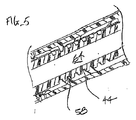
ここで図1〜図3を参照すると、組織を通して縫合糸を螺旋状に前進させるためのシステム10が、縫合糸展開デバイス12と、針−拡張器アセンブリ14とを備える。縫合糸展開デバイス12は、遠位端部16と、近位端部18と、中心通路とを有するハンドル36を備える。ノブ34が、以下により詳細に説明されるようにハンドルの近位端部22に回転可能に装着され、真っすぐな針24は、拡張器本体28の中心通路内に摺動可能に装着される。真っすぐな針は、以下により詳細に説明されるように、最初に、ラッチ要素30によって、縫合糸展開デバイス12のハンドルに対して不動化される。針24の遠位先端26は、針がラッチによってハンドル内に保持されているとき、典型的には、1cm〜3cmの短距離(典型的には、約1.5cm)だけレーン内で拡張器本体28の遠位に延在する。
With reference now to FIGS. 1-3, a
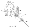
ここで特に図2を参照すると、縫合糸展開デバイス12は、ハンドル36の中心通路62内に装着されるシャトル部材38をさらに含む。便宜上、ハンドル36は、組立を促進するために2つのC形状のシェル36aおよび36bから形成される。一対の螺旋針40が、シャトル部材38の遠位端部上において螺旋溝42に取り付けられる。典型的には、螺旋針は、針の一巻きが絡み合わせられ、針が180°位相がずれるように装着される。螺旋トラック44が、シャトル部材38の外側表面上に形成され、螺旋トラックは、シャトル部材の回転がシャトル部材を軸方向に平行移動させることにより(回転方向に応じて)螺旋針40を展開または後退させるように、フォロワ58(図5)に係合する。レセプタクル46が1つずつ、ハンドル36の両側に形成され、各レセプタクルは、螺旋針40の各々に取り付けられる縫合糸長さ82を受け取るように構成される。レセプタクルは、取り外し可能なカバー48によって包囲され、縫合糸長さ82は、針が組織に移植されてシャトル展開デバイス12が組織上から引き抜かれた後、レセプタクルから展開される。
With particular reference now to FIG. 2, the
図3を参照すると、針−拡張器アセンブリ14の拡張器本体28は、遠位部分50と、中央部分52と、近位端部におけるフラッシュバックチャンバ32とを有する。スロット54が、以下により詳細に説明されるように、ラッチ部材30を受け取る中央部分内に形成される。
Referring to FIG. 3, the
ここで図4〜図6を参照すると、螺旋トラック44とハンドルの内側表面上に形成されるフォロワ58との間の係合が、より良好に見られること可能である。シャトル部材38は、以下に説明されるようにノブ34によって回転されることが可能であり、そのような回転は、螺旋トラックをハンドル36に据え付けられるフォロワ58上で前進させる。今度は、ノブ34は、シャトル部材38の近位部分に結合される。ハンドルは、外側シェルの手動回転が内側シェルを同様の態様で回転させるように、外側シェル34aと、同軸内側シェル34bとを含む。今度は、内側シェル34bは、シャトル部材38の近位部分の外側表面上に形成された軸方向スロットまたは同様のチャネルもしくはトラックに係合してその中を進行するピンまたは他の特徴部(図示せず)を有する。このように、ノブ34の回転は、シャトル部材38に付与され、シャトル部材を回転かつ軸方向に平行移動させるが、ノブがハンドルに対して平行移動するかまたは軸方向位置を変化させることを要求しない。ノブ34、ハンドル36、およびシャトル部材38の同心性質は、図6に最良に見られる。図6はまた、シャトル部材の全長に延在しかつ針−拡張器アセンブリ14にアクセス経路を提供するシャトルの中心通路64を示す。
With reference now to FIGS. 4-6, the engagement between the
窓68および70が、それぞれ、ハンドル36およびシャトル部材38内に形成されることにより、ユーザが、手術中に、通路64内の針−拡張器アセンブリ14を観察することと、シャトル部材38の回転および前進を観察することとを可能にする。
ここで図7Aおよび図7Bを参照すると、真っすぐな針24の遠位先端26は、手術の開始時、図7Aに示されるように、縫合糸展開デバイス12の遠位端部16から遠位に延在する。針24の遠位先端26は、針が患者の心臓の尖領域の近傍の典型的な心筋の厚さを通して前進させられることが可能であるように、ハンドル36の遠位端部を十分に越えて(典型的には、1cm〜3cm)延在する。ハンドル36の遠位先端はまた、典型的には、真っすぐな針24が心筋を通して穿通された後、心臓の心外膜に対して係合および安定化することが可能である滑り止め56を含む。図7Bに示されるように、螺旋針44(単数または複数)は、針が組織内へ穿通された後、ハンドル36から真っすぐな針24上で同軸方向にその組織内へ前進させられ得る。
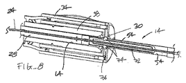
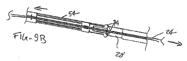
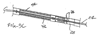
Referring now to FIGS. 7A and 7B, the distal tip 26 of the
ここで図8および図9A〜図9Cを参照すると、手術の開始時、針−拡張器アセンブリ14は、シャトル部材38の中心通路64内に存在し、ラッチ30によって、所定の位置に保持される。具体的には、ラッチ部材30は、ハンドルの近位端部に形成された溝76に係合する一対の戻り止め74を含む。ラッチ30は、ラッチが係脱されるまで針が移動しないように、真っすぐな針24に直接的に接続される。拡張器本体28は、戻り止め74を収容することによって拡張器本体が針上で前進させられることを可能にするスロット54を含む。しかしながら、戻り止め74は、半径方向内向きに閉鎖するようにばね荷重される(ばね状U形状フレームの端部に取り付けられている)が、拡張器本体とともに移動するように結合されるカム部材またはトラック72によって開放状態で保持される。図9Aに見られるように、拡張器本体28は、戻り止めがカム部材72によって完全に開放状態で保持されるように、最初に、針24に対して近位に完全に後退される。しかしながら、拡張器本体28が針に対して遠位に前進させられるにつれて、ラッチ部材は、図9Cに示されるようにカム部材端部およびラッチフレームばねが戻り止め74を半径方向に後退および閉鎖させるように閉鎖されるまで、図9Bおよび9Cに示されるように右に進行する。戻り止めが閉鎖されると、戻り止めは、ハンドル内の溝との係合から外れ、その結果、針は、今や、ハンドルへの取付なしに拡張器本体とともに自由に移動する。しかしながら、拡張器本体28は、針が偶発的に組織穿通するのを防ぐように、完全に前進されることにより針24を被覆する。
Referring now to FIGS. 8 and 9A-9C, at the beginning of surgery, the needle-
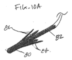
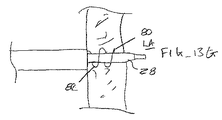
ここで図10Aおよび図10Bを参照すると、複数の自己展開式アームまたは返し84を有する例示的な組織アンカ80が、ある長さの縫合糸82に取り付けられ得る。自己展開式アームまたは返し84は、近位方向に放射状に広がり、その結果、アンカおよび縫合糸が、最小限の力で組織を通して遠位に前進し得るが、近位方向に後退されるときには有意な維持力で組織内に埋め込まれる。螺旋針40の遠位先端88は、他のアームが螺旋針の内側に完全に含まれたままである一方で組織アンカ80の単一アームまたは返し84が螺旋針の外側に突出することを可能にするスロット86を有する。自由組織アンカアーム84は、螺旋針が組織を通して遠位に駆動されるにつれて下方に撓曲し、螺旋針の回転が反転されることにより針を後退させると、露出したアーム84は、組織内へ穿通し、アンカ80は、所定の位置に展開する。螺旋針から解放されると、残りの組織アンカアーム84も同様に、組織内へ埋め込まれ、付加的な維持力を提供する。Tバー設計、接着剤ベースの設計、返し付き突起等の他のアンカ設計もまた、使用を見出し得る。通常、アンカは、組織内へ埋め込まれるが、縫合糸の遠位端部は、心腔または他の開放身体空洞内に係留され得るかまたは組織の壁から別の外部表面に退出し得、その結果、螺旋針は、アンカの使用をすることなく固定され得る。
Referring now to FIGS. 10A and 10B, an
いくつかの実施形態では、デバイスは、縫合糸の遠位端部におけるアンカが螺旋針の先端から心臓の外部の位置まで前進させられることが可能であるように構成され得る。例えば、アンカは、形状記憶合金から形成される鋭的ロッドまたは管であり得、ロッドまたは管は、螺旋針の遠位端部から前進させられることが可能である。前進するにつれて、形状記憶は、拡張器によって画定される中心軸の方にアンカ管を向け得る。アンカは、次いで、後続ステップにおける拡張器の取り除きが縫合糸の自由端部を引き抜くように、拡張器によって係合および捕捉され得、これは、アンカの移植なしに縫合糸端部を組織内に付着させるために「ループ状」縫合糸を作成する。 In some embodiments, the device may be configured such that an anchor at the distal end of the suture can be advanced from the tip of the spiral needle to a location outside the heart. For example, the anchor can be a sharp rod or tube formed from a shape memory alloy, and the rod or tube can be advanced from the distal end of the spiral needle. As it advances, the shape memory may direct the anchor tube towards the central axis defined by the dilator. The anchor can then be engaged and captured by the dilator so that removal of the dilator in a subsequent step pulls the free end of the suture, which causes the suture end to enter tissue without anchor implantation. Create a “looped” suture for attachment.
さらに他の実施形態では、上述のアンカは、前進させられるにつれて心臓組織から退出するように構成され得る。さらに他の実施形態では、デバイスは、回収構成要素を含み得、回収構成要素は、螺旋針が完全に前進させられると心臓組織に進入し、次いで、回収特徴部の取り除きがアンカを心臓組織の外に引くようにアンカと整列および係合するように構成される。ループ状縫合糸経路を心臓組織内に作成するためのさらに他のデバイスおよび方法もまた、本発明の原理内で採用され得る。 In still other embodiments, the anchor described above may be configured to exit the heart tissue as it is advanced. In still other embodiments, the device may include a retrieval component that enters the heart tissue when the helical needle is fully advanced, and then removal of the retrieval feature causes the anchor to be removed from the heart tissue. Configured to align and engage with the anchor to pull outward. Still other devices and methods for creating a looped suture path in heart tissue may also be employed within the principles of the present invention.
ここで図11、図12A、および図12Bを参照すると、閉鎖されるべき組織路を覆う外側組織表面上の縫合糸の自由端部は、プレジットを使用して緊締および「結束」され得、プレジットは、一方向にプレジットを通して縫合糸の通過を可能にするが反対方向には可能にしない機構を介して、縫合糸の「自動係止」を提供する。プレジットの使用は、プレジットが、結び目を作る必要なく設置後縫合糸を所定の位置に保持するため、有利である。加えて、プレジットは、組織平面に垂直な張力を保つことにより、非支持縫合糸が組織を切り開く傾向にある「チーズワイヤリング」の効果を最小限にする。 Referring now to FIGS. 11, 12A, and 12B, the free end of the suture on the outer tissue surface that covers the tissue tract to be closed can be clamped and “tied” using the pledget. Provides “automatic locking” of the suture through a mechanism that allows passage of the suture through the pledget in one direction but not in the opposite direction. The use of a pledget is advantageous because the pledget holds the suture in place after installation without the need to tie a knot. In addition, the pledget minimizes the effect of “cheese wiring” where unsupported sutures tend to cut through the tissue by maintaining tension perpendicular to the tissue plane.
図11に示されるように、プレジット90の第1の実施形態は、典型的にはステンレス鋼から作製されるアーム92を有し、アーム92は、基部94の方にではなく基部94から離れるように撓曲することを可能にされる。これは、アームがプレジット基部と平坦に固定されるため、アームが自由に外向きに撓曲するが、プレジットが反対方向に移動しないように防止する一方で、プレジット90が縫合糸材料に沿って容易に滑り落ちることを可能にする。プレジット基部は、単一の構成要素または複数の構成要素から構築され、それにより、心臓のトポロジとのより優れた共形化を可能にし得る。最後に、プレジットは、螺旋物/縫合糸およびプレジットの同時展開を可能にするために送達デバイスの先端に事前に適用されるか、または、ポートの挿入後、ポートの除去に先立って、後に適用され得る。外科手術の完了後、プレジット(単数または複数)は、縫合糸上に設置され得、縫合糸は、止血が達成されるまで引張される。
As shown in FIG. 11, a first embodiment of
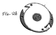
図12Aおよび12Bに示されるように、プレジット100は、基部ディスク104に回転可能に取り付けられるヘッドディスク102を備える。ディスクは、縫合糸を所定の位置に挟持および保持する閉鎖スロットを画定する対向挟持アーム106を画定する。スパー108およびピニオン110は、ディスクが所定の位置をはずれて回転することを防止する。縫合糸は、縫合糸挟持アーム間に設置され、位置決めおよび設置ツールのための把持特徴部(例えば、孔112)は、縫合糸挟持アームが緊密に確実に縫合糸をつかむようにディスクを回転させるために使用される。 As shown in FIGS. 12A and 12B, the pledget 100 includes a head disk 102 that is rotatably mounted to a base disk 104. The disk defines opposing clamping arms 106 that define a closed slot that clamps and holds the suture in place. The spar 108 and pinion 110 prevent the disk from rotating out of position. A suture is placed between the suture pinching arms, and a gripping feature (eg, hole 112) for the positioning and placement tool rotates the disc so that the suture pinching arm grasps the suture tightly and securely. Used for.
ここで図13A〜図13Kを参照すると、本発明の原理に従って、左心室または他の心腔に経心尖的にアクセスして心内手術を行うための例示的プロトコルが説明される。関連する生体構造は、図8Aに示されており、そこでは、患者の心臓Hの経心尖領域TAは、患者の肋骨の裏側で保護されている。アクセスは、概して、肋骨R4と肋骨R5との間の肋間空間を通して確保される。真っすぐな針24が心臓Hの経心尖領域TAに係合することが可能であるように、縫合糸展開デバイス12の遠位端部16が肋骨間に導入される。
Referring now to FIGS. 13A-13K, an exemplary protocol for performing intracardiac surgery with transapical access to the left ventricle or other heart chamber will be described in accordance with the principles of the present invention. The associated anatomy is shown in FIG. 8A, where the transapical region TA of the patient's heart H is protected behind the patient's ribs. Access is generally ensured through the intercostal space between rib R4 and rib R5. The
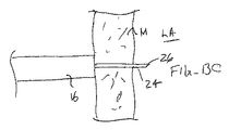
ここで図13Bおよび図13Cを参照すると、針24が、針の遠位端部26が左心房LAに進入するように、心筋Mを通して前進させられ得る。この時点で、血液は、中空針24に進入し、フラッシュバックチャンバ32へ逆流し、針が左心房に進入したことを医師が確認することを可能にする。
Referring now to FIGS. 13B and 13C, the
針の進入が確認された後、ノブ34は、螺旋針40(このうちの1つのみが図13Dに示される)を組織内へ回転および前進させるように回転されることが可能である。典型的には左心房内へではなく、心筋内へ針を所望の距離だけ延在させた後、針40の回転は反転され、縫合糸82を所定の位置に残す。典型的には、縫合糸82の遠位端部におけるアンカ80は、針が引き抜かれるにつれてある長さの縫合糸が螺旋パターンをとるように、密閉展開し、縫合糸の遠位端部を所定の位置に係留する。
After the needle entry is confirmed, the
縫合糸が適切に展開された後、拡張器本体28は、図13Fおよび図13Gに示されるように、左心房LA内へ針24上で前進させられ得る。拡張器本体28は前進させられるが、針は、上述の掛止機構30によりさらには前進しないことに留意されたい。したがって、拡張器本体は、図13Gに示されるように、針上を完全に前進する。
After the suture is properly deployed, the
拡張器本体28が完全に前進させられた後、縫合糸展開デバイス12は、引き抜かれ得、図13Hに示されるように、拡張器を所定の位置に残す。次いで、アクセスシースASが、図13Iに示されるように、拡張器本体28上で展開され得る。アクセスシースは、図13Jに示されるように、介入ツールITの導入を可能にし、その結果、先に挙げたものを含む種々の介入手術が行われ得る。介入手術が行われた後、図13Kに示されるように、介入ツールおよびアクセスシースは、引き抜かれ、縫合糸長さ82は、組織路TTを緊締するために、近位方向に引かれる。アンカ80は、所望の閉鎖を達成するために、組織内に残留し、縫合糸が緊締されることを可能にする。
After the
上記は、本発明の好ましい実施形態の完全な説明であるが、種々の代替、改変および均等物が使用され得る。したがって、上記の説明は、添付の特許請求の範囲によって画定される本発明の範囲を限定するものととられるべきではない。 While the above is a complete description of the preferred embodiments of the invention, various alternatives, modifications, and equivalents may be used. Therefore, the above description should not be taken as limiting the scope of the invention which is defined by the appended claims.
Claims (37)
遠位端部と、近位端部と、前記端部間に延在する中心通路とを有するハンドルと、
前記ハンドルの近位端部上に回転可能に担持されるノブと、
前記ハンドルの中心通路内に往復運動可能に配置されるシャトル部材であって、前記シャトル部材は、遠位端部と、近位端部と、前記端部間に延在する中心通路とを有する、シャトル部材と、
前記シャトル部材の遠位端部に結合される少なくとも1つの螺旋針と、
前記少なくとも1つの螺旋針によって解放可能に担持される縫合糸と
を備え、
前記ノブは、前記ノブの回転が前記シャトル部材を回転させかつ軸方向に平行移動させることにより前記少なくとも1つの螺旋針を回転および平行移動させるように、前記シャトル部材に結合され、前記ノブは、前記ノブが回転されるときに軸方向に平行移動しない、システム。 A system for helically advancing a suture through tissue, the system comprising:
A handle having a distal end, a proximal end, and a central passage extending between the ends;
A knob rotatably supported on the proximal end of the handle;
A shuttle member reciprocally disposed within a central passage of the handle, the shuttle member having a distal end, a proximal end, and a central passage extending between the ends. A shuttle member;
At least one helical needle coupled to the distal end of the shuttle member;
A suture releasably carried by the at least one helical needle;
The knob is coupled to the shuttle member such that rotation of the knob rotates and translates the at least one helical needle by rotating and axially translating the shuttle member; A system that does not translate axially when the knob is rotated.
ハンドルの遠位端部を患者の心臓の尖に対して位置付けることにより、真っすぐな針の遠位端部を心筋組織を通して心腔内へ前進させることと、
少なくとも1つの螺旋針を前記ハンドルの遠位端部から前記針を囲繞する心筋組織内へ回転および前進させることであって、前記少なくとも1つの螺旋針は、ある長さの縫合糸を担持する、ことと、
前記真っすぐな針を囲繞する少なくとも1つの螺旋針を逆回転および後退させることにより、前記心筋組織内の前記真っすぐな針を囲繞する螺旋経路内に前記ある長さの縫合糸を埋め込むことと、
前記埋め込まれた螺旋縫合糸内で前記真っすぐな針上で拡張器を前記ハンドルから前進させることであって、前記真っすぐな針は、前記拡張器が前進するときに前記針が前記心腔内へさらに前進することができないように前記ハンドルに掛止され、前記針は、前記拡張器が前記針を完全に被覆すると、前記ハンドルから掛止解除される、ことと、
前記拡張器上から前記ハンドルを取り除くことと、
前記拡張器上でアクセスシースを前進させることにより、前記心腔内への介入アクセスを提供することと、
を含む、方法。 A method for transapical access to the heart chamber, the method comprising:
Advancing the distal end of a straight needle through the myocardial tissue into the heart chamber by positioning the distal end of the handle relative to the apex of the patient's heart;
Rotating and advancing at least one spiral needle from a distal end of the handle into myocardial tissue surrounding the needle, the at least one spiral needle carrying a length of suture; And
Implanting the length of suture in a helical path surrounding the straight needle in the myocardial tissue by reversely rotating and retracting at least one helical needle surrounding the straight needle;
Advancing a dilator from the handle over the straight needle within the implanted spiral suture, wherein the straight needle moves the needle into the heart chamber as the dilator is advanced. Being hooked to the handle so that it cannot be advanced further, the needle being unlocked from the handle when the dilator completely covers the needle;
Removing the handle from on the dilator;
Providing interventional access into the heart chamber by advancing an access sheath over the dilator;
Including the method.
請求項17に記載のように、前記心腔にアクセスすることと、
前記螺旋縫合糸が所定の位置にある間、拡張された通路を通して少なくとも1つのツールを導入することと、
前記少なくとも1つのツールを用いて心臓手術を行うことと、
前記少なくとも1つのツールを前記拡張された通路から取り除くことと、
前記縫合糸を引っ張ることにより、前記拡張された通路を閉鎖することと
を含む、方法。 A method for performing cardiac surgery,
Accessing the heart chamber as in claim 17;
Introducing at least one tool through the expanded passage while the helical suture is in place;
Performing cardiac surgery using the at least one tool;
Removing the at least one tool from the expanded passage;
Closing the expanded passage by pulling the suture.
Applications Claiming Priority (3)
| Application Number | Priority Date | Filing Date | Title |
|---|---|---|---|
| US201462031694P | 2014-07-31 | 2014-07-31 | |
| US62/031,694 | 2014-07-31 | ||
| PCT/US2015/043312 WO2016019349A1 (en) | 2014-07-31 | 2015-07-31 | Systems and methods for helically advancing suture in tissue |
Publications (1)
| Publication Number | Publication Date |
|---|---|
| JP2017526416A true JP2017526416A (en) | 2017-09-14 |
Family
ID=55218389
Family Applications (1)
| Application Number | Title | Priority Date | Filing Date |
|---|---|---|---|
| JP2017505191A Pending JP2017526416A (en) | 2014-07-31 | 2015-07-31 | System and method for helically advancing a suture within tissue |
Country Status (5)
| Country | Link |
|---|---|
| US (1) | US20170135692A1 (en) |
| EP (1) | EP3174472A4 (en) |
| JP (1) | JP2017526416A (en) |
| CN (1) | CN106714704A (en) |
| WO (1) | WO2016019349A1 (en) |
Cited By (1)
| Publication number | Priority date | Publication date | Assignee | Title |
|---|---|---|---|---|
| JP7354077B2 (en) | 2019-09-30 | 2023-10-02 | ジャイラス エーシーエムアイ インク ディー/ビー/エー オリンパス サージカル テクノロジーズ アメリカ | Suturing device and method |
Families Citing this family (11)
| Publication number | Priority date | Publication date | Assignee | Title |
|---|---|---|---|---|
| JP5735928B2 (en) | 2009-03-14 | 2015-06-17 | バソスティッチ, インコーポレイテッド | Vascular access and closure device |
| US10327862B2 (en) * | 2014-09-17 | 2019-06-25 | Covidien Lp | Fiducial marker deployment system |
| US10492779B2 (en) * | 2017-02-20 | 2019-12-03 | Edwards Lifesciences Corporation | Suturing devices for heart valve surgery |
| CA3084628A1 (en) | 2017-12-14 | 2019-06-20 | Meacor Sal | Helical anchor driving system |
| CN109091177B (en) * | 2018-09-26 | 2020-02-14 | 武汉唯柯医疗科技有限公司 | Transapical interventional therapy access and closed recanalization device |
| CN109259829A (en) * | 2018-11-30 | 2019-01-25 | 谭昌明 | Artificial Intervention valve is adapted to mounting ring |
| CN109259830A (en) * | 2018-11-30 | 2019-01-25 | 谭昌明 | Artificial Intervention valve is adapted to mounting ring |
| CA3129151A1 (en) * | 2019-03-13 | 2020-09-17 | Lsi Solutions, Inc. | Surgical access system |
| US20210045773A1 (en) * | 2019-08-14 | 2021-02-18 | Ethicon, Inc. | Transseptal sheath with anchoring coil for controlled left atrial access |
| US20240050082A1 (en) * | 2020-12-18 | 2024-02-15 | The Johns Hopkins University | Perianal fistula closure system |
| CN114869376B (en) * | 2022-05-09 | 2023-03-10 | 南京鼓楼医院 | Atria stitching instrument under thoracoscope |
Family Cites Families (11)
| Publication number | Priority date | Publication date | Assignee | Title |
|---|---|---|---|---|
| SU715082A1 (en) * | 1977-01-24 | 1980-02-15 | Всесоюзный научно-исследовательский и испытательный институт медицинской техники | Surgical suturing apparatus |
| WO2007098212A2 (en) * | 2006-02-18 | 2007-08-30 | Amir Belson | Endoscopic suturing devices |
| US8696689B2 (en) * | 2008-03-18 | 2014-04-15 | Medtronic Ventor Technologies Ltd. | Medical suturing device and method for use thereof |
| US20120035654A1 (en) * | 2009-03-14 | 2012-02-09 | Vasostitch, Inc. | Methods and systems for advancing and anchoring suture in tissue |
| DE202010000329U1 (en) * | 2009-04-09 | 2010-05-27 | Aesculap Ag | Surgical instruments |
| US20100274129A1 (en) * | 2009-04-24 | 2010-10-28 | Hooven Michael D | Apparatus And Methods for Separating Pericardial Tissue From The Epicardium of the Heart |
| WO2011067770A1 (en) * | 2009-12-02 | 2011-06-09 | Valtech Cardio, Ltd. | Delivery tool for implantation of spool assembly coupled to a helical anchor |
| WO2011112721A1 (en) * | 2010-03-09 | 2011-09-15 | University Of Louisville Research Foundation, Inc. | Endoscopic closure device |
| EP2584977A4 (en) * | 2010-06-26 | 2017-08-09 | Vasostitch, Inc. | Method and apparatus for transapical access and closure |
| US20120089159A1 (en) * | 2010-09-20 | 2012-04-12 | Shluzas Alan E | System for tensioning a surgical closure |
| US9226824B2 (en) * | 2010-11-30 | 2016-01-05 | Edwards Lifesciences Corporation | Surgical stabilizer and closure system |
-
2015
- 2015-07-31 EP EP15827084.3A patent/EP3174472A4/en not_active Withdrawn
- 2015-07-31 WO PCT/US2015/043312 patent/WO2016019349A1/en active Application Filing
- 2015-07-31 JP JP2017505191A patent/JP2017526416A/en active Pending
- 2015-07-31 CN CN201580051061.3A patent/CN106714704A/en active Pending
-
2017
- 2017-01-30 US US15/419,971 patent/US20170135692A1/en not_active Abandoned
Cited By (2)
| Publication number | Priority date | Publication date | Assignee | Title |
|---|---|---|---|---|
| JP7354077B2 (en) | 2019-09-30 | 2023-10-02 | ジャイラス エーシーエムアイ インク ディー/ビー/エー オリンパス サージカル テクノロジーズ アメリカ | Suturing device and method |
| US11826040B2 (en) | 2019-09-30 | 2023-11-28 | Gyrus Acmi, Inc. | Suturing apparatus and method |
Also Published As
| Publication number | Publication date |
|---|---|
| EP3174472A4 (en) | 2018-02-28 |
| EP3174472A1 (en) | 2017-06-07 |
| US20170135692A1 (en) | 2017-05-18 |
| WO2016019349A1 (en) | 2016-02-04 |
| CN106714704A (en) | 2017-05-24 |
Similar Documents
| Publication | Publication Date | Title |
|---|---|---|
| JP2017526416A (en) | System and method for helically advancing a suture within tissue | |
| US20220313229A1 (en) | Device for applying a knot to a suture | |
| JP5869565B2 (en) | Method and apparatus for transapical access and closure | |
| EP2265188B1 (en) | Medical suturing device | |
| EP2498685B1 (en) | System for providing access and closure to tissue | |
| EP1463451B1 (en) | Device for endoscopic suturing | |
| US20090024146A1 (en) | System, apparatus, and method for repairing septal defects | |
| US8998933B2 (en) | Surgical fastening clips, systems and methods for proximating tissue | |
| JP2005525137A (en) | Needle device and method for septal defect closure | |
| JP2010506663A (en) | Knot extrusion tool | |
| US11406375B2 (en) | Pursestring suture retractor and method of use | |
| US10136885B2 (en) | Three suture large bore closure device and methods |