JP2017525860A - Knee orthosis - Google Patents
Knee orthosis Download PDFInfo
- Publication number
- JP2017525860A JP2017525860A JP2016575178A JP2016575178A JP2017525860A JP 2017525860 A JP2017525860 A JP 2017525860A JP 2016575178 A JP2016575178 A JP 2016575178A JP 2016575178 A JP2016575178 A JP 2016575178A JP 2017525860 A JP2017525860 A JP 2017525860A
- Authority
- JP
- Japan
- Prior art keywords
- strap
- base
- knee brace
- knee
- tension strap
- Prior art date
- Legal status (The legal status is an assumption and is not a legal conclusion. Google has not performed a legal analysis and makes no representation as to the accuracy of the status listed.)
- Pending
Links
Images


Classifications
-
- A—HUMAN NECESSITIES
- A61—MEDICAL OR VETERINARY SCIENCE; HYGIENE
- A61F—FILTERS IMPLANTABLE INTO BLOOD VESSELS; PROSTHESES; DEVICES PROVIDING PATENCY TO, OR PREVENTING COLLAPSING OF, TUBULAR STRUCTURES OF THE BODY, e.g. STENTS; ORTHOPAEDIC, NURSING OR CONTRACEPTIVE DEVICES; FOMENTATION; TREATMENT OR PROTECTION OF EYES OR EARS; BANDAGES, DRESSINGS OR ABSORBENT PADS; FIRST-AID KITS
- A61F5/00—Orthopaedic methods or devices for non-surgical treatment of bones or joints; Nursing devices; Anti-rape devices
- A61F5/01—Orthopaedic devices, e.g. splints, casts or braces
- A61F5/0102—Orthopaedic devices, e.g. splints, casts or braces specially adapted for correcting deformities of the limbs or for supporting them; Ortheses, e.g. with articulations
- A61F5/0104—Orthopaedic devices, e.g. splints, casts or braces specially adapted for correcting deformities of the limbs or for supporting them; Ortheses, e.g. with articulations without articulation
- A61F5/0106—Orthopaedic devices, e.g. splints, casts or braces specially adapted for correcting deformities of the limbs or for supporting them; Ortheses, e.g. with articulations without articulation for the knees
-
- A—HUMAN NECESSITIES
- A41—WEARING APPAREL
- A41D—OUTERWEAR; PROTECTIVE GARMENTS; ACCESSORIES
- A41D13/00—Professional, industrial or sporting protective garments, e.g. surgeons' gowns or garments protecting against blows or punches
- A41D13/05—Professional, industrial or sporting protective garments, e.g. surgeons' gowns or garments protecting against blows or punches protecting only a particular body part
- A41D13/055—Protector fastening, e.g. on the human body
- A41D13/0556—Protector fastening, e.g. on the human body with releasable fastening means
- A41D13/0568—Protector fastening, e.g. on the human body with releasable fastening means with straps
-
- A—HUMAN NECESSITIES
- A41—WEARING APPAREL
- A41D—OUTERWEAR; PROTECTIVE GARMENTS; ACCESSORIES
- A41D13/00—Professional, industrial or sporting protective garments, e.g. surgeons' gowns or garments protecting against blows or punches
- A41D13/05—Professional, industrial or sporting protective garments, e.g. surgeons' gowns or garments protecting against blows or punches protecting only a particular body part
- A41D13/06—Knee or foot
- A41D13/065—Knee protectors
-
- A—HUMAN NECESSITIES
- A61—MEDICAL OR VETERINARY SCIENCE; HYGIENE
- A61F—FILTERS IMPLANTABLE INTO BLOOD VESSELS; PROSTHESES; DEVICES PROVIDING PATENCY TO, OR PREVENTING COLLAPSING OF, TUBULAR STRUCTURES OF THE BODY, e.g. STENTS; ORTHOPAEDIC, NURSING OR CONTRACEPTIVE DEVICES; FOMENTATION; TREATMENT OR PROTECTION OF EYES OR EARS; BANDAGES, DRESSINGS OR ABSORBENT PADS; FIRST-AID KITS
- A61F13/00—Bandages or dressings; Absorbent pads
- A61F13/06—Bandages or dressings; Absorbent pads specially adapted for feet or legs; Corn-pads; Corn-rings
- A61F13/061—Bandages or dressings; Absorbent pads specially adapted for feet or legs; Corn-pads; Corn-rings for knees
- A61F13/062—Openable readjustable
Landscapes
- Health & Medical Sciences (AREA)
- Vascular Medicine (AREA)
- Orthopedic Medicine & Surgery (AREA)
- Engineering & Computer Science (AREA)
- Biomedical Technology (AREA)
- Heart & Thoracic Surgery (AREA)
- Nursing (AREA)
- Life Sciences & Earth Sciences (AREA)
- Animal Behavior & Ethology (AREA)
- General Health & Medical Sciences (AREA)
- Public Health (AREA)
- Veterinary Medicine (AREA)
- Orthopedics, Nursing, And Contraception (AREA)
- Professional, Industrial, Or Sporting Protective Garments (AREA)
Abstract
【課題】膝の保護及び支持を必要とするアスリート及びその他の者によって使用される膝装具を提供することにある。【解決手段】膝装具は、ベースとスパイダー部材とを含む。ベースは、弾性材料で構成され、膝の部分及び隣接した脚部分の周りにぴったりするように形成されている。上下対の引張ストラップを有するスパイダー部材は、ベースの内側面に固定され、引張ストラップは、ベースの外側面との着脱可能な取り付けのためにベースに設けた上下穴を貫いて延びる。PROBLEM TO BE SOLVED: To provide a knee orthosis used by athletes and others who need knee protection and support. A knee brace includes a base and a spider member. The base is made of an elastic material and is formed to fit around the knee and adjacent leg portions. A spider member having a pair of upper and lower tensile straps is secured to the inner surface of the base, and the tensile straps extend through upper and lower holes provided in the base for detachable attachment with the outer surface of the base.
Description
本発明は、一般的には、人が付けて身体の損傷,尤度,又は再燃を減らす物品の分野に関し、特に、膝に着用される装具の分野に関する。 The present invention relates generally to the field of articles worn by humans to reduce body damage, likelihood, or relapse, and more particularly to the field of braces worn on the knee.
膝を損傷から守り且つ既存の損傷の悪化を回避する可撓性の膝装具は、活発な物理的活動に携わるアスリート及び他の人によって使用される。膝は、歩行や走りを含むどんな活動にも使用されるので、膝は、身体の最も激しく使用される関節の1つである。膝は、膝が支えなければならない比較的高い応力レベルのために、損傷の共通の主題でもある。物理的な労働を伴う職業では、正常な足行中、特に、激しいスポーツ中、膝は、急速な方向変換,疲労,でこぼこ面,又は衝撃の結果、異常な運動を受けることがある。これらの異常運動は、関節突起脱臼,伸張,又は膝を包む組織の断裂を含む捻挫又はもっと酷い損傷、を引き起こすことがある。 Flexible knee braces that protect the knee from injury and avoid exacerbating existing injuries are used by athletes and others involved in active physical activity. Since the knee is used for any activity, including walking and running, the knee is one of the most heavily used joints in the body. The knee is also a common subject of injury due to the relatively high stress levels that the knee must support. In occupations involving physical labor, during normal gait, especially during intense sports, the knees may experience abnormal movement as a result of rapid turning, fatigue, bumpy surface, or impact. These abnormal movements can cause sprains or more severe damage, including articular process dislocation, stretching, or tearing of the tissue surrounding the knee.
いくつかの異なるタイプの異常な運動は、膝に損傷を引き起こすことがある。第1に、膝が、その正常な前後仕様で、しかし正常な運動範囲を超えて曲がるような膝関節の過伸長・過屈曲損傷が起こることがある。第2のタイプの異常な運動は、下肢が膝関節を中心に、大腿部に対して回転的に捻られる、軸回転である。第3の異常な運動は、膝関節が、正常な前後運動の代わりに、左右に曲がる、大腿部に対する下肢の横曲げである。加えて、膝蓋骨(膝頭)の異常な運動は、膝蓋骨の下面の軟化又は変性及び膝蓋骨の亜脱臼としても知られる、膝蓋骨の関節突起脱臼の様な損傷をもたらすことがある。 Several different types of abnormal movement can cause damage to the knee. First, the knee joint may be overstretched and bent over, with its normal anterior and posterior specifications, but bending beyond the normal range of motion. The second type of abnormal movement is axial rotation, where the lower limb is rotationally twisted relative to the thigh around the knee joint. The third abnormal movement is lateral bending of the lower limb with respect to the thigh, where the knee joint bends left and right instead of normal back and forth movement. In addition, abnormal movement of the patella (kneecap) can result in damage such as articular process dislocation of the patella, also known as softening or degeneration of the lower surface of the patella and subluxation of the patella.
膝を異常な運動から守る手段が異なるタイプの運動から守る能力が変わるいろいろの特殊な実施態様で多年使用されてきた。膝を異常な運動から守ることの外に、膝を暖かくしておくために膝を覆うこと、膝を衝撃から守ること、又は不快を減らすために膝を圧迫すること、のような付加的な利点を提供する。しかしながら、これらの手段によって異常な運動に対して与えられる保護は、正常な運動の範囲又は容易さの減少をしばしば伴う。これらの手段は、また、脚に加えられる重さ,硬い構成部品によって引き起こされる自己損傷又は他人への損傷の可能性、付け外しの困難性,コスト,外観及び皮膚の刺激又は摩擦のような他の望ましくない面を持っていることがある。 The means of protecting the knee from abnormal movements has been used for many years in a variety of special embodiments that vary in their ability to protect from different types of movement. In addition to protecting the knee from abnormal movements, such as covering the knee to keep it warm, protecting the knee from shock, or compressing the knee to reduce discomfort Provides benefits. However, the protection afforded to abnormal movement by these means is often accompanied by a reduction in the range or ease of normal movement. These measures also include the weight applied to the legs, the possibility of self-injury or damage to others caused by hard components, difficulty in removal, cost, appearance and other such as skin irritation or friction. May have an undesirable side of.
これらの理由のために、長いこと、先行技術の手段の望ましくない面を回避しながら、正常な運動の範囲又は容易さに悪影響を及ぼすことなく、膝を異常な運動から守ることができる改善した膝装具を見いだす動機付けがあった。 For these reasons, it has long been possible to protect the knee from abnormal movement without adversely affecting the range or ease of normal movement while avoiding the undesirable aspects of prior art means. There was a motivation to find knee orthosis.
第1の実施形態では、本発明による膝装具は、ベースと、対の上下引張ストラップを有するスパイダー部材とを含み、スパイダー部材は、ベースの外側面に恒久的に固定される。 In a first embodiment, a knee brace according to the present invention includes a base and a spider member having a pair of upper and lower tension straps, the spider member being permanently fixed to the outer surface of the base.
本発明の他の面によれば、本発明による膝装具は、ベースと、対の上下引張ストラップを有するスパイダー部材とを含み、スパイダー部材は、ベース及びスパイダー部材の中間線軸線を通る複数の縫い目によってベースに恒久的に固定される。 According to another aspect of the present invention, a knee brace according to the present invention includes a base and a spider member having a pair of upper and lower tension straps, the spider member having a plurality of seams passing through the base line and the midline axis of the spider member. Is permanently fixed to the base.
本発明の他の面によれば、本発明による膝装具は、対の上下穴を有するベースと、着用されるときベースと脚との間に位置し、かつ対の上下引張ストラップを有するスパイダー部材とを含み、引張ストラップは、膝装具が着用されるとき、ベースの穴を貫いて延びる。 According to another aspect of the present invention, a knee brace according to the present invention comprises a base having a pair of upper and lower holes, a spider member positioned between the base and the leg when worn and having a pair of upper and lower tensile straps. The tension strap extends through the hole in the base when the knee brace is worn.
第2の実施形態では、本発明による膝装具は、ベースと、例えば、米国でスパンデックス又はエラスサンとして知られ又は登録商標LYCRAのもとに販売されているタイプの、あらゆる方向に比較的弾性である合成繊維で形成された有形引張部材とを含むが、これは要求されず他の材料を使用してもよい。引張部材は、ベースの内側面に恒久的に固定され、そしてベースの穴を貫いて延びる自由端を有し、フックとループファスナー材料を使用して、自由端をベースの外側面に固定することができ、第3の実施形態では、1つ以上の弾性ステーを追加の支持体のために設けることもできる。 In a second embodiment, the knee orthosis according to the invention is relatively elastic in all directions, with a base and, for example, the type known in the United States as spandex or elastane or sold under the registered trademark LYCRA A tangible tension member formed of synthetic fibers, but this is not required and other materials may be used. The tension member is permanently fixed to the inner surface of the base and has a free end that extends through a hole in the base and uses a hook and loop fastener material to secure the free end to the outer surface of the base In the third embodiment, one or more elastic stays can be provided for additional supports.
第4の実施形態では、本発明による膝装具は、ベースと、外部メッシュ層と、例えば、米国でスパンデックス又はエラスサンとして知られ又は登録商標LYCRAのもとに販売されているタイプの、あらゆる方向に比較的弾性である合成繊維で形成された上下クロスストラップとを含むが、これは要求されず他の材料を使用してもよい。クロスストラップは、ベースの内側面に恒久的に固定され、ベースの穴を貫いて第2の(自由)端まで延びる第1の端を有し、第2の自由端は、フックとループファスナー材料を使用して、ベースの外側面に固定可能である。ストラップは、例えば、第2の(自由)端の近くに非弾性部分を含んでもよい。 In a fourth embodiment, the knee brace according to the invention is in any direction, of the base, the outer mesh layer, for example of the type known in the United States as spandex or elastane or sold under the registered trademark LYCRA. Including upper and lower cross straps formed of relatively elastic synthetic fibers, but this is not required and other materials may be used. The cross strap is permanently secured to the inner surface of the base and has a first end that extends through a hole in the base to a second (free) end, the second free end being a hook and loop fastener material Can be fixed to the outer surface of the base. The strap may include, for example, an inelastic portion near the second (free) end.
ストラップの非弾性部分は、弾性材料の代わりに、非弾性材料を望む場所に、例えば、付けられるとき、穴の近くの場所から自由端まで延びる非弾性材料を使用することによって形成することができる。変形例として、非弾性材料は、弾性材料の部分と非弾性材料のストラップの追加の層とをサンドイッチにし及び又は重ね合わせることによって形成されてもよい。重ねあわされ又はサンドイッチにされたならば、出来たサンドイッチの一方の側は、キー、アクセスホォブ,ID又はクレジットカード、スマートデバイス(例えば、フィットネストラッカー)又は、明るい着色物,反射物,点滅ライト,発光棒又は他の照明のような可視フレアーの様な小さい物を入れるポケットを形成するように開き放しにしておくのがよい。このような場合、外部メッシュ層は、好ましくは、フレアー又は照明を見えるようにするために、メッシュ又は他の透明もしくは半透明材料で作られる。着用者の可視性を高めるために1つ以上の反射パッチを設けてもよい。 The inelastic portion of the strap can be formed in place of the elastic material by using an inelastic material that extends to the free end from the location near the hole when attached, e.g., where it is desired. . Alternatively, the inelastic material may be formed by sandwiching and / or overlapping portions of the elastic material and additional layers of straps of inelastic material. Once overlaid or sandwiched, one side of the resulting sandwich can be a key, access hob, ID or credit card, smart device (eg fitness tracker) or bright colored object, reflector, flashing light, light emitting It may be left open to form a pocket for small objects such as bars or other lighting such as visible flare. In such cases, the outer mesh layer is preferably made of mesh or other transparent or translucent material to make flare or illumination visible. One or more reflective patches may be provided to increase wearer visibility.
本発明の更なる目的,特徴及び利点は、以下の詳細な説明から、添付図面について考慮されるとき、明らかであろう。 Further objects, features and advantages of the present invention will become apparent from the following detailed description when considered in conjunction with the accompanying drawings.
[発明の関係説明]
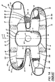
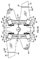
図面を参照すると、図1A及び1B刃、米国特許第5,472,413号に教示された設計と似た先行技術の膝装具20を示しており、その内容をここに援用する。先行技術の膝装具20は、ベース部材22及びスパイダー部材24を含み、その各々は、弾性材料の平らなシート26を所望形状に裁断することによって作られる。ベース部材22の外側面31は、好ましくは、織物支持繊維ループ28で被覆され、繊維ループは、繊維ループ及びフック型材料が互いに押しつけられる時フック型材料に付着する。
[Explanation of the relationship of the invention]
Referring to the drawings, there is shown a prior
先行技術の膝装具20のベース22は、上縁36から下縁38まで垂直に延びるベース中央部分30を有し、かつベース中央部分30の中央を垂直に走る中心線軸40を有する。ベース22は、中央部分30から延びる、第1の上取付ストラップ32A、第2の上取付ストラップ32B、第1の下取付ストラップ34A、第2の下取付ストラップ34Bを含む。
The
ベース22の内側面39を示す図1Bにおそらく最もよく示すように、第1上取付ストラップ32Aと第1下取付ストラップ34Aは、ベース部材22の外側面31の織物支持繊維ループ28との分離可能な取付けに適したフック型ストラップファスナータブ46で終わっている。ストラップファスナータブ46は縫い目48で取付ストラップに縫いつけられている。
As best shown in FIG. 1B showing the
ベースはまた、膝装具が着用されるとき、膝頭を受け入れる膝頭開口2を有している。ベースは、膝装具が着用されるとき、ひだ付け(バンチング)を防止する凹部74を含むように形成されるのがよい。ベースは、好ましくは、縁取りを含むが、これらの特徴のどれも要求されない。
The base also has a kneecap opening 2 that receives the kneecap when the knee brace is worn. The base may be formed to include a
ベース22の外側面31を示す図1Aにおそらく最もよく示すように、先行技術の膝装具20は、スパイダー部材24を含む。スパイダー部材24は、上縁56から下縁58まで垂直に延びるスパイダー部材中央部分54を有し、かつスパイダー部材中央部分54の中央を垂直に走る中心線軸60を有する。スパイダー部材24は、スパイダー部材中央部分54の周囲に延びる縫い目72でベース22の外側面31に恒久的に取り付けられている。
Prior
スパイダー部材24は、中央部分54から延びる第1上引張ストラップ62A,第2上引張ストラップ62B,第1下引張ストラップ64A,下引張ストラップ64Bを含む。引張ストラップ 62A,62B,64A,64Bの各々は、ベース22の外側面の織物28との着脱可能な取付に適し、かつ縫い目68で引張ストリップに縫いつけられたフック型ファスナータブ66で終わっている。スパイダー部材24は、また、膝装具を付けるとき、膝頭を受け入れる膝頭開口部を有している。
The
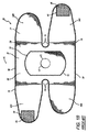
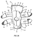
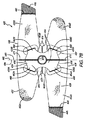
図2A及び2Bは、平に置かれた本発明による膝装具120の外側平面図、内側平面図をそれぞれ示す。膝装具120は、ベース部材122及びスパイダー部材124を含み、その各々は、弾性材料の平なシート126を所望形状に裁断することによって作られる。ベース部材122の外面は、好ましくは、織物支持繊維ループ128で被覆され 該織物支持繊維ループは、繊維ループとフック型材料が互いに押しつけられるときフック型材料に付着する。
2A and 2B respectively show an outer plan view and an inner plan view of a
膝装具120のベース122は、上縁136から下縁138まで垂直方向に延びるベース中央部分130を有し、かつベース中央部分130の中間を垂直に走る中心線軸140を有する。ベース122は、中央部分30から延びる、第1の上取付ストラップ132A、第2の上取付ストラップ132B、第1の下取付ストラップ134A、第2の下取付ストラップ134Bを含む。
The
ベース122の内側面139を示す、おそらく図2Bに最もよく示すように第1の上取付ストラップ132A及び第1の下取付ストラップ134Aは、ベース122の外側面131上の織物支持繊維ループ128との着脱可能な取付に適した、フック型ストラップファスナータブ146で終わっている。フック型ストラップファスナータブ146は、縫い目148で取付ストラップに縫いつけられている。
A first
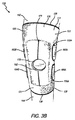
図4A及び4Bに最もよく示すように、膝装具120のベース122が人の脚に当てられるとき、第1上取付ストラップ132Aは脚の後で第2上取付ストラップ132Bに重なり、膝装具120を着用者の上脚142の周りに留めるために、第1上取付ストラップの端のフック型ファスナータブ146を第2上取付ストラップ132Bの外側面の織物支持繊維ループ128に付着させる。同様に、膝装具120を着用者の下脚144の周りに留めるために、第1下取付ストラップ134Aが脚の後で第2下取付ストラップ134Bに重なってこれに付着する。
As best shown in FIGS. 4A and 4B, when the
ベース122は,また好ましくは、膝装具が着用されるとき、膝頭を受け入れる膝頭開口部152を有する。膝頭開口部152は、膝頭の大きさに合致するから着用者の膝頭は、膝装具120が付けられるとき膝頭開口部152から延びるが、このことは必要ではない。膝頭開口部152は好ましくは、形状が円形であるが、これは必要ではなく、ダイヤモンド形、卵形、長方形又は正方形の様な他の形状を使用してもよい。直接的な膝頭の安定を提供することに加えて、膝頭開口部152は、膝装具120の適用中膝装具を膝頭に関して位置するのを助ける。
The base 122 also preferably has a
ベース122は、上取付ストラップ132A,132Bと下取付ストラップ134A,134Bとの間に凹部174を含むように形成されるのがよく、膝装具120が脚に付けられるとき、各側のギャップは、膝の後に開口部を形成するが、これは、要求されるものではない。凹部174は、こすれを回避するのを助け、風通しを提供し、バンチング、すなわち動きの不当な制限を回避するのを助ける。
The base 122 may be formed to include a
ベース122は、好ましくは、図2A、2Bに示すように、治療加温と共に、膝領域に対する一般化したサポート及び圧迫を提供する弾性材料のシートで作られた再閉鎖可能なスリープとして形成されるが、他の材料を使用してもよい。ベース122は、また、例えば、膝及びそれに隣接した脚部分の周りにぴったりと合うように形成された管状弾性スリープとして形成されてもよい。ベースは、好ましくは縁取りを含むが、これらの特徴のいずれも要求されない。
The
ベース122の内側面139を示す図2Bにおそらく最もよく示すように、膝装具120は、スパイダー部材124を含む。スパイダー部材124は、上縁156から下縁158まで垂直に延びるスパイダー部材154を有し、かつスパイダー部材中央不文154の中間を垂直に走る中心線軸160を有する。スパイダー部材124の中央部分154は、スパイダー部材中央部分54の中心線軸160に沿って延びる縫い目171によってベース122の内側面139に恒久的に取り付けられている。
As best shown in FIG. 2B, which shows the
スパイダー部材124は、中央部分154から延びる第1上引張ストラップ162A,第2上引張ストラップ162B,第1下引張ストラップ164A,下引張ストラップ164Bを含む。引張ストラップ162A,162B,164A,164Bの各々は、ベース122の外側面の織物支持繊維ループ128との着脱可能な取付に適し、かつ縫い目168で引張ストラップに縫いつけられたフック型ファスナータブ166で終わっている。スパイダー部材124は、また、膝装具が付けられるとき、膝頭を受け入れる膝頭開口部を有している。
The
先行技術の膝装具20と本発明による膝装具120との間にはある類似性があるけれども、(限定ではなく)少なくとも3つの重要な特徴がある。第1に、先行技術の膝装具20のスパイダー部材24は、ベース22の外側面31に留められる。対比して、本発明による膝装具120のスパイダー部材124は、ベース122の内側面139に留められる。
Although there are certain similarities between the prior
第2に、先行技術の膝装具20のスパイダー部材24は、スパイダー部材中央部分54の周囲に延びる縫い目72によってベース22に留められる。対比して、膝装具120のスパイダー部材124は、スパイダー部材154の中心線軸160に沿って延びる縫い目171によってベース122に留められる。
Second, the
第3に、先行技術の膝装具20のスパイダー部材24の中央部分54と引張ストラップ62A、62B,64A,64Bの両方は、通常の使用中ベース22の外側面31にある。対比して、膝装具120では、スパイダー部材124の中央部分154は、ベース122の内側面138にあり、引張ストラップ162A,162B,164A,164Bは、穴33A,133B,135A,135Bを貫いて延びてベース122の外側面131に達する。
Third, both the central portion 54 of the
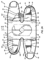
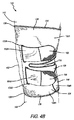
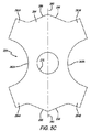
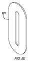
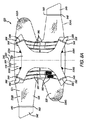
図5A,5Bh、本発明による膝装具の第二の実施形態の平面図であり、膝装具を平に置いて膝装具の外側面及び内側面を露出させて示している。膝装具220は、ベースの内側面に恒久的に固定された有形張力部材224(図5Cに分離して示す)を有している。膝装具220は、また穴補強ベース237A及び穴補強裏当て237Bで形成された補強穴237を含む(図5D,Eに分離して示す)。
5A and 5Bh are plan views of a second embodiment of a knee brace according to the present invention, wherein the knee brace is placed flat and the outer and inner surfaces of the knee brace are exposed. The
膝装具220は、ベース部材222及び有形引張部材224を含み、各々1つ以上のエラストマー材料の平面シート226を所望の形状に裁断することによって作られる。ベース部材222の外面は、好ましくは、織物支持繊維ループ228で被覆され、該繊維ループは、該繊維ループとフック型材料が互いに押しつけられる時フック型材料に付着する。有形張力部材224は、好ましくは、あらゆる方向に比較的弾力性である合成繊維で形成されており、係る合成繊維は、例えば、米国ではスパンデックスとして又はエラスサンとして知られ、もしくは 登録商標LYCRAのもとに販売されているタイプのものであるが、これは要求されるものではなく、他の材料を使用してもよい。
膝装具220のベース222は、上縁236から下縁238まで垂直に延びるベース中央部分230を有し、かつベース中央部分230の中間を垂直に走る中間線軸線240を有する。ベース222は、中央部分から延びる、第1の上取付ストラップ232A,第2の上取付ストラップ232Bと第1の下取付ストラップ234A,第2の下取付ストラップ234Bを含む。ベース222は、また、第1の上穴233A,第2の上穴233B,第1の下穴235A,第2の下穴235Bを含み、これらはすべて、ベース222に補強穴237として形成される。
The
ベース222の内側面239を示す、図5Bにおそらく最もよく示すように、第1の上取付ストラップ232A及び第1の下取付ストラップ234Aは、ベース222の外側面231の織物支持繊維ループ228との着脱可能な取付けに適したフック型ファスナータブ246で終わっている。フック型ファスナータブ246は縫い目248で引張ストラップに縫いつけられている。
The first upper mounting
膝装具220は、図3A−3B及び4A−4Bに示す膝装具120と同様な仕方で人の脚に当てられそして固定される。ベース222は、また、好ましくは、膝装具を付けるとき膝頭を受け入れる膝頭開口部252を有し、上取付ストラップ232A,232Bと下取付ストラップ234A,234Bとの間に側凹部274を含むように形成されるのがよい。ベースは、好ましくは、縁取り76を含むが、これらの特徴はいずれも要求されない。
The
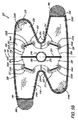
ベース222の内側面239を示す図5Bに、おそらく最もよく示すように、膝装具220は、有形引張部材224を含む。図5Cにおそらく最もよく示すように、有形引張部材224は、中央部分254,上縁256,下縁258,第1の横側263A,第2の横側263B及び中央部分中間線軸線260を有する。有形引張部材224は、また第1の上引張ストラップ262A,第2の上引張ストラップ262B,第1の下引張ストラップ264A,第2の下引張ストラップ264Bを含む。有形引張張力部材224は、ベース222の外側面の織物支持繊維ループ228との着脱可能な取付けに適し、縫い目268で引張ストラップに縫いつけられたフック型ファスナータブ266で終わっている。有形引張部材224は、膝頭開口部270を含み、かつ中央部分254の中間線軸線260に沿って延びる中間線縫い目271によってベース222に恒久的に取り付けられるのがよい。
As perhaps best shown in FIG. 5B showing the
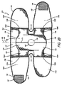
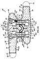
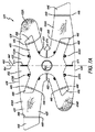
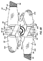
図6A−6Bは、本発明による膝装具320の第3の実施形態の平面図であり、膝装具を平に置いて膝装具の外側面及び内側面を露出させている。膝装具320は、弾性ステーを有しかつベースの内側面に恒久的に固定された上下クロス弾性ストラップを有している。膝装具320は、また補強穴337を含む。
6A-6B are plan views of a third embodiment of a
膝装具320は、1つ以上のエラストマー材料の平らなシート326を所望形状に裁断することによって作られたベース部材322を含む。ベース部材の外側面331は、好ましくは、織物支持繊維ループ328で被覆され、織物支持繊維ループ328は、該繊維ループ328とフック型材料が互いに押しつけられたときフック型材料に付着する。膝装具320は、また上クロスストラップ324及び下クロスストラップ325を含み、これらストラップは、好ましくは、ストラップの長さに沿って弾性である材料で形成される。
膝装具320のベース322は、上縁336から下縁338まで垂直に延びるベース中央部分330を有し、且つベース中央部分330の中間を垂直に走る中間線軸線340を有する。ベース322は、中央部分330から延びる、第1の上取付ストラップ332A,第2の上取付ストラップ332B,第1の下取付ストラップ334A,第2の下取付ストラップ334Bを含む。ベース322は、また、第1の上穴333A,第2の上穴333B,第1の下穴335A,第2の下穴335Bを含み、これらはすべて、ベース322に補強穴337として形成される。
The
ベース322の内側面339を示す図2Bにおそらく最もよく示すように、第1の上取付ストラップ332A及び第1の下取付ストラップ334Aは、ベース322の織物支持繊維ループ328との着脱可能な取付けに適したフック型ファスナータブ346で終わっている。フック型ファスナータブ346は縫い目348で取付ストラップに縫いつけられている。
As perhaps best shown in FIG. 2B showing the
膝装具320は、図3A−3B及び図4A−4Bに示す膝装具120と同じ仕方で人の脚に付けられそして固定される。ベース322は、また、好ましくは、膝装具を付けるとき膝頭を受け入れる膝頭開口部352を有し、上取付ストラップ332A,332Bと下取付ストラップ334A,334Bとの間に凹部374を含むように形成されるのがよい。ベースは、好ましくは、縁取り376を含むが、これらの特徴はいずれも要求されない。
The
ベース322の内側面339を示す図5Bにおそらく最もよく示すように、膝装具320は、中央部分354を有する上クロスストラップ324及び中央部分355を有する下クロスストラップ325を含む。クロスストラップは、中間線軸線360を有する。上クロスストラップ324は、第1の上クロス引張ストラップ362A及び第2の上クロス引張ストラップ362Bを含む。下クロスストラップ325は、第1の下クロス引張ストラップ364A及び第2の下クロス引張ストラップ364Bを含む。引張ストラップは、ベース322の外側面の織物支持繊維ループ328との着脱可能な取付けに適し、且つ縫い目368で引張ストラップに縫いつけられたフック型ベルクロ(登録商標)ファスナータブ366で終わっている。ベース322は、膝頭バットレス370を含むのがよい。上クロスストタラップ324及び下クロスストラップ325は、中間線軸線360に沿って延びる縫い目371によって且つクロスストラップの固定端で縫い目363A,363B,365A,365Bによってベース322に恒久的に取り付けられている。
As perhaps best shown in FIG. 5B showing the
ベース320は、追加の横支持体、例えば、弾性ステーチャンネル縫い目380によってベースに固着された追加のシート材料を使用して形成されたポケット381の中に入れられた1つ以上の弾性ステー382(図7Eに示す)を含むのがよい。
The base 320 may include one or more elastic stays 382 (encased in a
図7A−7Bは、本発明による膝装具420の第4の実施形態の平面図であり、膝装具を平に置いて膝装具の外側面及び内側面を露出させている。図5A−5Bと同様に、膝装具420は、全ての方向に比較的弾性である合成繊維で形成され、ベースの内側面に恒久的に固定された有形引張部材424(図7Cに分離して示す)を有する。膝装具420はまた、補強穴437及び外側メッシュ層480(図7Dに分離して示す)を含む。
7A-7B are plan views of a fourth embodiment of a
膝装具420は、ベース部材422及び有形引張部材424を含み、その各々は、1つ以上のエラストマー材料野平らなシート426を所望形状に裁断することによって作られる。ベース部材422の外面は、好ましくは、織物支持繊維ループ428で被覆され、繊維ループは、該繊維ループとフック型材料が互いに押しつけられるとき、フック型材料に付着する。有形引張部材424は、好ましくは、あらゆる方向に比較的弾力性である合成繊維で形成されており、係る合成繊維は、例えば、米国ではスパンデックスとして又はエラスサンとして知られ、もしくは 登録商標LYCRAのもとに販売されているタイプのものであるが、これは要求されるものではなく、他の材料を使用してもよい。
膝装具420のベース422は、上縁436から下縁438まで垂直に延びるベース中央部分430を有し、かつベース中央部分430の中間を垂直に走る中間線軸線440を有する。ベース422は、中央部分430分から延びる、第1の上取付ストラップ432A,第2の上取付ストラップ432B,第1の下取付ストラップ434A,第2の下取付ストラップ434Bを含む。ベース422は、また、第1の上穴433A,第2の上穴433B,第1の下穴435A,第2の下穴435Bを含み、これらはすべて、ベース422に補強穴4237として形成される。
The
ベース422の内側面439を示す図7Bにおそらく最もよく示すように、第1の上取付ストラップ432A及び第1の下取付ストラップ434Aは、ベース422の外側面431の織物支持繊維ループ428との着脱可能な取付けに適したフック型ストラップファスナータブ446で終わっている。フック型ストラップファスナータブ446は縫い目448で取付ストラップに縫いつけられ、反射物、発光物、暗闇発光材、又は明るい色のような1つ以上のフレア手段449を含んでもよい。
As perhaps best shown in FIG. 7B showing the
膝装具420は、図3A−3B及び4A−4Bに示す膝装具120と同様な仕方で人の脚に付けられそして固定される。ベース422はまた、好ましくは、膝装具が付けられるとき膝頭を受け入れる膝頭開口部452を有する。ベース422は、上取付ストラップ432A,432Bと下取付ストラップ434A,434Bとの間に凹部474を含むように形成されるのがよい。ベース422は、脚にもっと密着するようにベースに外形を付ける多重のシートを使用して、又は簡単な切り込みを付けて、もしくは縫い目453を付けて形成されてもよい。
ベース422の内側面439を示す図7Bにおそらく最もよく示すように、膝装具420は、中央部分454、上縁456,下縁458,第1の横側463A,第2の横側463B,及び中央部分中間線軸線460を有する有形引張部材424を含む。有形引張部材424はまた、第1の上取付ストラップ462A,第2の上取付ストラップ462B,第1の下取付ストラップ464A,第2の下取付ストラップ464Bを含む。図7Cにおそらく最もよく示すように、引張ストラップは、1つ以上の非丹精部分465を含むのがよい。
As perhaps best shown in FIG. 7B showing the
有形引張部材424は、ベース422の外側面431の織物支持繊維ループ428との着脱可能な取付けに適したフック型ファスナータブ466で終わっていて、縫い目468で引張ストラップに縫いつけられている。有形引張部材424は、膝頭開口部470を含むのがよくまた中間線縫い目471によりベースに恒久的に取り付けられるのがよい。
The
図7Aにおそらく最もよく示すように、膝装具420は、外側メッシュ層480を含む。図7Dに示すように、外側メッシュ層480は、上縁481,下縁482,中間線軸線484,第1の上アーム486A,第2の上アーム486B,第1の横側487A,第2の横側487B,第1の下アーム488A及び第2の下アーム488Bを有する。外側メッシュ層480は、第1のストラップの端の近くで第1の上引張ストラップに、第2のストラップの端の近くで第2の上引張ストラップに、第3のストラップの端の近くで第1の下引張ストラップに、第4のストラップの端の近くで第2の引張ストラップにそれぞれ恒久的に固定されている。外側メッシュ層480は、ベース422に取り付けられなくてもよい。
As perhaps best shown in FIG. 7A,
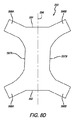
図8A−8Bは、本発明による膝装具520の第5の実施形態を示し、膝装具を平に置いて膝装具の外側面及び内側面を露出させている。図6A−6Bの膝装具320と同様に、膝装具520は、膝装具の内側面に恒久的に固定された上下クロス弾性ストラップを有する。膝装具529はまた、補強穴537及び弾性ステー582を含み、且つ外側メッシュ層590(図8Dに示す)を有する。
8A-8B show a fifth embodiment of a
膝装具520は、1つ以上のエラストマー材料の平らなシート526を所望形状に裁断することによって作られたベース部材522を含む。ベース部材522の外面は、好ましくは、織物支持繊維ループ528で被覆され、該繊維ループは、繊維ループとフック型材料が互いに押しつけられるとき、フック型材料に付着する。膝装具520は、また好ましくは、ストラップの長さに沿って弾性である材料で形成された上クロスストラップ524及び下クロスストラップ525を含む。
膝装具520のベース522は、上縁536から下縁538まで垂直方向に延びるベース中央部分530を有し、且つベース中央部分530の中間を垂直方向に走る中間線軸線540を有する。ベース522は、中央部分530から延びる、第1の上取付ストラップ532A,第2の上取付ストラップ52B,第1の下取付ストラップ534A,第2の下取付ストラップ534Bを含む。ベース522は、また、第1の上穴533A,第2の上穴533B,第1の下穴535A,第2の下穴535Bを含み、これらはすべて、ベース522に補強穴537として形成される。
The base 522 of the
ベース522の内側面539を示す図8Bにおそらく最もよく示すように、第1の上取付ストラップ532A及び第1の下取付ストラップ534Aは、ベース522の外側面531の織物支持繊維ループ528との着脱可能な取付けに適したフック型ストラップファスナータブ546で終わっている。フック型ストラップファスナータブ546は縫い目548で取付ストラップに縫いつけられている。
As best shown in FIG. 8B showing the
膝装具520は、図3A−3B及び4A−4Bに示す膝装具120と同様の仕方で脚に付けられ、そして固定される。ベース522はまた、好ましくは、膝装具が着用されるとき、膝頭を受け入れる膝頭開口部552を有する。ベース522は、上取付ストラップ532A,532Bと下取付ストラップ534A,534Bとの間に凹部574を含むように形成されるのがよい。
ベース522の内側面539を示す図2Bに最もよく示すように、膝装具520は、中央部分554を有する上クロスストラップ524及び中央部分555を有する下クロスストラップ525を含む。クロスストラップは、中間線軸線560を有する。上クロスストラップ524は、第1の上引張ストラップ562A及び第2の上クロス引張ストラップ562Bを含む。下クロスストラップ525は、第1の下引張ストラップ564A及び第2の下クロス引張ストラップ564Bを含む。引張ストラップは、ベース522の外側面531の織物支持繊維ループ528との着脱可能な取付けに適し、縫い目568で取付ストラップに縫いつけられているフック型ベルクロ(登録商標)ファスナータブ566で終わっている。ベース522は、膝頭バットレス(控え壁)570を含むのがよい。上クロスストラップ424及び下クロスストラップ525は、中間線軸線560に沿って延びる中間線縫い目571によって、またクロスストリップの固定端で縫い目563A,563B,565A,565Bによってベース522に恒久的に取り付けられるのがよい。
As best shown in FIG. 2B showing the
ベース520は、追加の横支持体、例えば、弾性ステーチャンネル縫い目580によってベースに固着された、追加のシート材料を使用して形成されたポケット581の中に入れられた1つ以上の弾性ステー582を含むのがよい。
The
図8Aにおそらく最もよく示すように、膝装具520は、外側メッシュ層590を含む。図8Dに示すように、外側メッシュ層590は、上縁591,下縁592,中間線軸線594,第1の上アーム596A,第2の上アーム596B,第1の横側597A,第2の横側597B,第1の下アーム598A及び第2の下アーム598Bを有する。外側メッシュ層590は、第1のストラップの端の近くで第1の上引張ストラップに、第2のストラップの端の近くで第2の上引張ストラップに、第3のストラップの端の近くで第1の下引張ストラップに、第4のストラップの端の近くで第2の下引張ストラップにそれぞれ恒久的に固定される。外側メッシュ層590は、ベース422に取り付けられなくてもよい。
As perhaps best shown in FIG. 8A,
本発明による膝装具の変形態様に関して種々の可能生がある。
好ましい実施形態では、膝装具は、弾性材料のシートから作られた再閉鎖可能なスリープとして形成されるベースを含んでいるが、これは、要求されない。例えば、ベースはまた、膝及び隣接した脚部分にぴったりと合うように成形された管状の弾性スリーブで形成されてもよい。ベースは、膝頭開口部を含む必要はなく、もしあるとすれば、膝頭開口部は、種々の形状、例えば、円形,正方形,矩形,楕円形、菱形,台形又は任意の実質的な均等を有してもよい。係る全ての変形態様をベースとしてここに参照する。
There are various possibilities for the deformation of the knee brace according to the invention.
In a preferred embodiment, the knee brace includes a base formed as a reclosable sleep made from a sheet of elastic material, but this is not required. For example, the base may also be formed of a tubular elastic sleeve shaped to fit snugly over the knee and adjacent leg portions. The base need not include a patella opening, if any, the patella opening may have various shapes, for example, round, square, rectangular, elliptical, rhombus, trapezoidal or any substantially equivalent. May be. Reference is made here to all such variants.
好ましい実施形態では、ベースの横側は各々上ファスナーストラップと下ファスナーストラップとの間に側凹部を設けて上下ファスナーストラップで終わっているが、これは要求されない。例えば、ベースの側又はその部分はまっすぐであってもよい。 In a preferred embodiment, the lateral sides of the base each end with upper and lower fastener straps with a side recess between the upper and lower fastener straps, but this is not required. For example, the side of the base or part thereof may be straight.
好ましい実施形態では、ベースは、互いに押しつけられたとき、付着するタイプのフック及びループ材料を使用して、着用者の脚の周りに着脱自在に固定されるが、これは要求されない。例えば、ボタン,留め金,バックル,ピン,ジッパーストラップ又は他の代替均等物のような他のファスナーをフック及びループ型ファスナー材料の代わりに使用してもよい。 In a preferred embodiment, the base is removably secured around the wearer's leg using a hook and loop material of the type that attaches when pressed against each other, although this is not required. For example, other fasteners such as buttons, clasps, buckles, pins, zipper straps or other alternative equivalents may be used in place of the hook and loop type fastener materials.
好ましい実施形態では、種々の構成部品が縫い目を使用して互いに恒久的に固定されているが、これは要求されない。例えば、糊、熱接着又は他の実質的な均等物のような他の手段を使用してもよい。 In the preferred embodiment, the various components are permanently secured to each other using seams, but this is not required. For example, other means such as glue, thermal bonding or other substantial equivalent may be used.
脚を支持して異常な運動から脚を保護するために、膝装具のベースの片側又は両側に1つ以上の直立した支持部材を設けているか、これは要求されない。直立支持部材は、例えば、細長い側ポケットの中に弾性ステー部材を入れることによって形成されるのがよい。弾性ステー部材は、種々のタイプの装具に通常使用される在来の構成の、ステンレススチール又は他の可撓性材料の偏平螺旋コアーで構成されるのがよい。 One or more upstanding support members are provided or not required on one or both sides of the knee brace base to support the leg and protect it from abnormal movement. The upright support member may be formed, for example, by placing an elastic stay member in the elongated side pocket. The elastic stay member may be composed of a flat helical core of stainless steel or other flexible material in a conventional configuration commonly used for various types of appliances.
細長い側ポケットは、例えば、側ポケットカバーストリップをベースに固定する垂直な縫い目間に形成されるのがよい。側ポケットカバーストリップはベースと同じ弾性シート材料で作られるのがよいが、これは必要ではない。縁取りは側ポケットカバーストリップの縁に固定されるのがよいが、これは、必要ではない。 The elongate side pockets may be formed, for example, between vertical seams that secure the side pocket cover strip to the base. The side pocket cover strip may be made of the same elastic sheet material as the base, but this is not necessary. The border may be secured to the edge of the side pocket cover strip, but this is not necessary.
直立支持部材の正確な数、場所及び構造は、設けられるならば、変えてもよい。例えば、たった1つの直立支持部材を形成する単一の細長い側ポケットであってもよいし或いは弾性ステーを各細長い側ポケットに入れて、膝の各側に1つ以上の細長い側ポケットであってもよい。細長い側ポケットは、弾性ステーの取り出しを可能にすべく一端が開けられるのがよく、その結果、膝装具を洗うことができ、或いは、異なる弾性ステーを差し込んで、設けられる支持体の量及び形式を調整してもよい。直立支持部材は、機械的ヒンジ、プラスチックロッド,金属ロッド, 補強シート材料の狭いストリップ,又は実質的な均等物もしくはこれらの種々の代替物を含んでもよい。 The exact number, location and structure of upright support members may vary if provided. For example, it may be a single elongate side pocket that forms only one upright support member, or there may be one or more elongate side pockets on each side of the knee with an elastic stay in each elongate side pocket. Also good. The elongated side pockets should be opened at one end to allow removal of the elastic stay, so that the knee brace can be washed, or a different elastic stay can be inserted and the amount and type of support provided. May be adjusted. Upright support members may include mechanical hinges, plastic rods, metal rods, narrow strips of reinforcing sheet material, or substantial equivalents or various alternatives thereof.
有利には、本発明による膝装具の前の外側面は、いかなる構造をも支持せず、スパイダー部材をベースの内側に固着する縫い目を除いて平滑であるのがよい。平滑な外側面を、例えば、使用中障害にならず、或いは運動を妨げない魅力的でクリーンな概観を提供するように維持されるのがよい。変形例はして、フットボールのような接触スポーツ用の、或いはコンクリート又は床タイル仕事のような職業用の厚い膝パッドのような他の構造、もしくはバレーボールのようなスポーツ用の滑り材料を特別な用途のため外側面に位置させてもよい。 Advantageously, the front outer surface of the knee brace according to the present invention does not support any structure and should be smooth except for the seam that secures the spider member to the inside of the base. The smooth outer surface may be maintained, for example, to provide an attractive and clean overview that does not become an obstacle during use or that does not interfere with movement. Variations may include special sliding materials for contact sports such as football, or other structures such as thick knee pads for occupation such as concrete or floor tile work, or sports such as volleyball. It may be located on the outer surface for use.
本発明は、例示としてここに記載された実施形態に限られるものではなく、特許請求の範囲の精神内に属する様な形態をすべて含むことは理解される。 It is understood that the present invention is not limited to the embodiments described herein by way of example, but includes all such forms that fall within the spirit of the claims.
Claims (20)
(b)第1の上引張ストラップ,第2の上引張ストラップ,第1の下引張ストラップ及び第2の下引張ストラップを有するスパイダー部材とを含み、
スパイダー部材は、ベースの内側面に恒久的に固定される、膝装具。 (A) a base that can be worn in a tightly covering relationship with a portion of a person's leg knee and its adjacent portion, and has an outer surface and an inner surface when worn;
(B) a spider member having a first upper tension strap, a second upper tension strap, a first lower tension strap, and a second lower tension strap;
The knee brace, wherein the spider member is permanently fixed to the inner surface of the base.
(b)第1の上引張ストラップ,第2の上引張ストラップ,第1の下引張ストラップ及び第2の下引張ストラップを有するスパイダー部材とを含み、
ベースは、ベース中央部分中間線軸線を有し、スパイダー部材は、スパイダー部材中央部分中間線軸線を有し、スパイダー部材は、ベース中央部分中間線軸線の少なくとも一部分及びスパイダー部材中央中間線軸線の少なくとも一部分を通る複数の縫い目によってベースに恒久的に固定される、膝装具。 (A) a base that can be worn in a tightly covering relationship with a portion of a person's leg knee and its adjacent portion, and has an outer surface and an inner surface when worn;
(B) a spider member having a first upper tension strap, a second upper tension strap, a first lower tension strap, and a second lower tension strap;
The base has a base center portion midline axis, the spider member has a spider member center portion midline axis, and the spider member has at least a portion of the base center portion midline axis and at least one of the spider member center midline axes. A knee brace that is permanently secured to the base by a plurality of seams that run through it.
(b)第1の上引張ストラップ,第2の上引張ストラップ,第1の下引張ストラップ及び第2の下引張ストラップを有するスパイダー部材とを含み、
スパイダー部材は、着用されるときベースと人の脚との間に位置し、
ベースは、第1の上穴、第2の上穴,第1の下穴及び第2の下穴を含み、
第1の上引張ストラップは、第1の上穴を貫いて延び、第2の上引張ストラップは、第2の上穴を貫いて延び、第1の下引張ストラップは、第1の下穴を貫いて延び、第2の下引張ストラップは、膝装具が着用されるとき、第2の上穴を貫いて延びる、膝装具。 (A) a base that can be worn in a tightly covering relationship with a portion of a person's leg knee and its adjacent portion, and has an outer surface and an inner surface when worn;
(B) a spider member having a first upper tension strap, a second upper tension strap, a first lower tension strap, and a second lower tension strap;
The spider member is located between the base and the person's leg when worn,
The base includes a first upper hole, a second upper hole, a first pilot hole, and a second pilot hole;
The first upper tension strap extends through the first upper hole, the second upper tension strap extends through the second upper hole, and the first lower tension strap extends through the first upper hole. A knee brace that extends through and the second lower tension strap extends through the second upper hole when the knee brace is worn.
引張ストラップの自由端は、ベースの外側面に着脱自在に取り付けられる、請求項9の膝装具。 At least a portion of the outer surface of the base supports the loop-type material, and the first upper tensile strap, the second upper tensile strap, the first lower tensile strap, and the second lower tensile strap support the hook-type material. Has a free end to
The knee brace of claim 9, wherein the free end of the tension strap is removably attached to the outer surface of the base.
請求項9の膝装具。 The base has a base center portion midline axis, the spider member has a spider member center portion midline axis, and the spider member has at least a portion of the base center portion midline axis and at least one of the spider member center midline axes. Permanently fixed to the base by a plurality of seams passing through a part,
The knee orthosis according to claim 9.
(b)あらゆる方向に弾性である材料で形成され、第1の上引張ストラップ,第2の上引張ストラップ,第1の下引張ストラップ及び第2の下引張ストラップを有する有形引張部材とを含み、
有形引張部材は、ベースの内側面に恒久的に固定される、膝装具。 (A) a base that can be worn in a tightly covering relationship with a portion of a person's leg knee and its adjacent portion, and has an outer surface and an inner surface when worn;
(B) a tangible tension member formed of a material that is elastic in all directions and having a first upper tension strap, a second upper tension strap, a first lower tension strap, and a second lower tension strap;
The tangual tension member is a knee brace that is permanently fixed to the inner surface of the base.
第1の上引張ストラップは、第1の上穴を貫いて第1のトラップ端まで延び、第2の上引張ストラップは、第2の上穴を貫いて第2のストラップ端まで延び、第1の下引張ストラップは、第1の下穴を貫いて第3のストラップ端まで延び、第2の下引張ストラップは、第2の下穴を貫いて第4のストラップ端まで延び、
第1のストラップ端,第2のストラップ端,第3のストラップ端,及び第4のストラップ端は、膝装具が着用されるときベースの外側面に着脱自在に取り付けられる、膝装具。 The base includes a first upper hole, a second upper hole, a first pilot hole, and a second pilot hole;
The first upper tension strap extends through the first upper hole to the first trap end, and the second upper tension strap extends through the second upper hole to the second strap end, The lower tension strap extends through the first pilot hole to the third strap end, the second lower tension strap extends through the second pilot hole to the fourth strap end,
The knee brace, wherein the first strap end, the second strap end, the third strap end, and the fourth strap end are detachably attached to the outer surface of the base when the knee brace is worn.
(b)ベースの内側面に恒久的に固定され、長い弾性材料で形成され、第1の上クロス引張ストラップ及び第2の上クロス引張ストラップを含む、上クロスストラップと、
(c) ベースの内側面に恒久的に固定され、長い弾性材料で形成され、第1の下クロス引張ストラップ及び第2の下クロス引張ストラップを含む、下クロスストラップと、を含み、
第1の上クロス引張ストラップは、第1の上穴を貫いて第1のトラップ自由端まで延び、第2の上クロス引張ストラップは、第2の上穴を貫いて第2のストラップ端まで延び、第1の下クロス引張ストラップは、第1の下穴を貫いて第3のストラップ端まで延び、第2の下引張ストラップは、第2の下穴を貫いて第4のストラップ端まで延び、
第1のストラップ端,第2のストラップ端,第3のストラップ端,及び第4のストラップ端は、膝装具が着用されるときベースの外側面に着脱自在に取り付けられる、膝装具。 (A) Wearable in a tightly covering relationship with the knee portion of a person's leg and its adjacent portion, including a first upper hole, a second upper hole, a first prepared hole and a second prepared hole A base having an outer surface and an inner surface when
(B) an upper cross strap permanently secured to the inner surface of the base and formed of a long elastic material, including a first upper cross tension strap and a second upper cross tension strap;
(C) a lower cross strap permanently secured to the inner surface of the base and formed of a long elastic material, including a first lower cross tension strap and a second lower cross tension strap;
The first upper cross tension strap extends through the first upper hole to the first trap free end, and the second upper cross tension strap extends through the second upper hole to the second strap end. The first lower cross tension strap extends through the first pilot hole to the third strap end, the second lower tension strap extends through the second pilot hole to the fourth strap end,
The knee brace, wherein the first strap end, the second strap end, the third strap end, and the fourth strap end are detachably attached to the outer surface of the base when the knee brace is worn.
Applications Claiming Priority (5)
| Application Number | Priority Date | Filing Date | Title |
|---|---|---|---|
| US201462016765P | 2014-06-25 | 2014-06-25 | |
| US201462016750P | 2014-06-25 | 2014-06-25 | |
| US62/016,765 | 2014-06-25 | ||
| US62/016,750 | 2014-06-25 | ||
| PCT/US2015/037815 WO2015200711A1 (en) | 2014-06-25 | 2015-06-25 | Knee brace |
Publications (2)
| Publication Number | Publication Date |
|---|---|
| JP2017525860A true JP2017525860A (en) | 2017-09-07 |
| JP2017525860A5 JP2017525860A5 (en) | 2018-07-12 |
Family
ID=54938825
Family Applications (1)
| Application Number | Title | Priority Date | Filing Date |
|---|---|---|---|
| JP2016575178A Pending JP2017525860A (en) | 2014-06-25 | 2015-06-25 | Knee orthosis |
Country Status (5)
| Country | Link |
|---|---|
| EP (1) | EP3160277B1 (en) |
| JP (1) | JP2017525860A (en) |
| CN (1) | CN106659256B (en) |
| ES (1) | ES2759601T3 (en) |
| WO (1) | WO2015200711A1 (en) |
Families Citing this family (3)
| Publication number | Priority date | Publication date | Assignee | Title |
|---|---|---|---|---|
| EP3473218B1 (en) * | 2017-10-23 | 2021-09-01 | 3M Innovative Properties Company | Area management of tissue sites on articulating joints |
| ES2722248B2 (en) * | 2018-02-07 | 2020-03-03 | Gil Francisco Javier Fernandez | Dynamic complement to protect and support the tibial plateau, kneecap and knee |
| DE102021107712A1 (en) | 2021-03-26 | 2022-09-29 | Adrian Eugen Pavel | knee pad |
Citations (2)
| Publication number | Priority date | Publication date | Assignee | Title |
|---|---|---|---|---|
| US5472413A (en) * | 1994-10-07 | 1995-12-05 | Pro Orthopedic Devices, Inc. | Universal fit knee and elbow braces with spiders |
| JP2009056103A (en) * | 2007-08-31 | 2009-03-19 | Pigeon Corp | Knee supporter |
Family Cites Families (11)
| Publication number | Priority date | Publication date | Assignee | Title |
|---|---|---|---|---|
| US3463147A (en) * | 1966-06-28 | 1969-08-26 | Frank F Stubbs | Body joint support |
| CA2089658A1 (en) * | 1990-08-17 | 1992-02-18 | E. Paul France | Patella-femoral brace |
| US6080121A (en) * | 1999-06-17 | 2000-06-27 | Becton, Dickinson And Company | Laminated orthopedic brace |
| US6402712B1 (en) * | 1999-08-16 | 2002-06-11 | Cho-Pat, Inc. | Dual action knee strap |
| US20030204156A1 (en) * | 2002-04-26 | 2003-10-30 | Nelson Ronald E. | Knee brace with patella stabilizer |
| US20040225245A1 (en) * | 2003-05-05 | 2004-11-11 | Nelson Ronald E. | Knee brace with directional elastic |
| US7708708B2 (en) * | 2004-07-22 | 2010-05-04 | Nordt Development Co., Ltd. | Donning potentiating support with expandable framework fastened to garment |
| US7882568B2 (en) * | 2006-07-19 | 2011-02-08 | Terence Fee | Two piece knee pad |
| CN200948346Y (en) * | 2006-09-06 | 2007-09-19 | 彪仕医技股份有限公司 | Lateral supporting type kneecap guard for health caring |
| US7959590B2 (en) * | 2007-04-19 | 2011-06-14 | New Options Sports | Method of and apparatus for patella support |
| ES2644458T3 (en) * | 2013-03-01 | 2017-11-29 | Mueller Sports Medicine, Inc. | Knee pad |
-
2015
- 2015-06-25 WO PCT/US2015/037815 patent/WO2015200711A1/en active Application Filing
- 2015-06-25 JP JP2016575178A patent/JP2017525860A/en active Pending
- 2015-06-25 CN CN201580045769.8A patent/CN106659256B/en active Active
- 2015-06-25 EP EP15812726.6A patent/EP3160277B1/en active Active
- 2015-06-25 ES ES15812726T patent/ES2759601T3/en active Active
Patent Citations (2)
| Publication number | Priority date | Publication date | Assignee | Title |
|---|---|---|---|---|
| US5472413A (en) * | 1994-10-07 | 1995-12-05 | Pro Orthopedic Devices, Inc. | Universal fit knee and elbow braces with spiders |
| JP2009056103A (en) * | 2007-08-31 | 2009-03-19 | Pigeon Corp | Knee supporter |
Also Published As
| Publication number | Publication date |
|---|---|
| ES2759601T3 (en) | 2020-05-11 |
| EP3160277A4 (en) | 2018-02-14 |
| CN106659256B (en) | 2020-06-23 |
| CN106659256A (en) | 2017-05-10 |
| EP3160277A1 (en) | 2017-05-03 |
| EP3160277B1 (en) | 2019-10-02 |
| WO2015200711A1 (en) | 2015-12-30 |
Similar Documents
| Publication | Publication Date | Title |
|---|---|---|
| US11058568B2 (en) | Knee brace | |
| US5500955A (en) | Knee pad for athletes | |
| US10159588B1 (en) | Self adjusting knee brace | |
| EP0608354B1 (en) | Adjustable knee support | |
| US20050038367A1 (en) | Adjustable knee stabilizer | |
| US10350104B2 (en) | Orthopedic brace and method of making the same | |
| JP6452676B2 (en) | Ankle orthosis | |
| US8007454B1 (en) | Ankle support assembly and method of supporting an ankle | |
| US9254215B2 (en) | Knee brace | |
| US11147702B2 (en) | Elbow brace | |
| US20200100928A1 (en) | Ankle brace devices, systems, and methods | |
| JP2018076628A (en) | Waist supporter | |
| JP2017525860A (en) | Knee orthosis | |
| US8784349B1 (en) | Knee brace | |
| KR20190090819A (en) | Trunk Supporter and Wear with it | |
| JP6357490B2 (en) | Knee orthosis | |
| JP3121832U (en) | Knee supporter | |
| TWI757414B (en) | Article of wear |
Legal Events
| Date | Code | Title | Description |
|---|---|---|---|
| RD04 | Notification of resignation of power of attorney |
Free format text: JAPANESE INTERMEDIATE CODE: A7424 Effective date: 20170426 |
|
| A521 | Request for written amendment filed |
Free format text: JAPANESE INTERMEDIATE CODE: A523 Effective date: 20180529 |
|
| A621 | Written request for application examination |
Free format text: JAPANESE INTERMEDIATE CODE: A621 Effective date: 20180529 |
|
| A977 | Report on retrieval |
Free format text: JAPANESE INTERMEDIATE CODE: A971007 Effective date: 20190311 |
|
| A131 | Notification of reasons for refusal |
Free format text: JAPANESE INTERMEDIATE CODE: A131 Effective date: 20190418 |
|
| A601 | Written request for extension of time |
Free format text: JAPANESE INTERMEDIATE CODE: A601 Effective date: 20190718 |
|
| A521 | Request for written amendment filed |
Free format text: JAPANESE INTERMEDIATE CODE: A523 Effective date: 20190917 |
|
| A02 | Decision of refusal |
Free format text: JAPANESE INTERMEDIATE CODE: A02 Effective date: 20200213 |