CN106659256B - Knee protector - Google Patents
Knee protector Download PDFInfo
- Publication number
- CN106659256B CN106659256B CN201580045769.8A CN201580045769A CN106659256B CN 106659256 B CN106659256 B CN 106659256B CN 201580045769 A CN201580045769 A CN 201580045769A CN 106659256 B CN106659256 B CN 106659256B
- Authority
- CN
- China
- Prior art keywords
- base
- brace
- knee
- knee brace
- band
- Prior art date
- Legal status (The legal status is an assumption and is not a legal conclusion. Google has not performed a legal analysis and makes no representation as to the accuracy of the status listed.)
- Active
Links
Images


Classifications
-
- A—HUMAN NECESSITIES
- A61—MEDICAL OR VETERINARY SCIENCE; HYGIENE
- A61F—FILTERS IMPLANTABLE INTO BLOOD VESSELS; PROSTHESES; DEVICES PROVIDING PATENCY TO, OR PREVENTING COLLAPSING OF, TUBULAR STRUCTURES OF THE BODY, e.g. STENTS; ORTHOPAEDIC, NURSING OR CONTRACEPTIVE DEVICES; FOMENTATION; TREATMENT OR PROTECTION OF EYES OR EARS; BANDAGES, DRESSINGS OR ABSORBENT PADS; FIRST-AID KITS
- A61F5/00—Orthopaedic methods or devices for non-surgical treatment of bones or joints; Nursing devices; Anti-rape devices
- A61F5/01—Orthopaedic devices, e.g. splints, casts or braces
- A61F5/0102—Orthopaedic devices, e.g. splints, casts or braces specially adapted for correcting deformities of the limbs or for supporting them; Ortheses, e.g. with articulations
- A61F5/0104—Orthopaedic devices, e.g. splints, casts or braces specially adapted for correcting deformities of the limbs or for supporting them; Ortheses, e.g. with articulations without articulation
- A61F5/0106—Orthopaedic devices, e.g. splints, casts or braces specially adapted for correcting deformities of the limbs or for supporting them; Ortheses, e.g. with articulations without articulation for the knees
-
- A—HUMAN NECESSITIES
- A41—WEARING APPAREL
- A41D—OUTERWEAR; PROTECTIVE GARMENTS; ACCESSORIES
- A41D13/00—Professional, industrial or sporting protective garments, e.g. surgeons' gowns or garments protecting against blows or punches
- A41D13/05—Professional, industrial or sporting protective garments, e.g. surgeons' gowns or garments protecting against blows or punches protecting only a particular body part
- A41D13/055—Protector fastening, e.g. on the human body
- A41D13/0556—Protector fastening, e.g. on the human body with releasable fastening means
- A41D13/0568—Protector fastening, e.g. on the human body with releasable fastening means with straps
-
- A—HUMAN NECESSITIES
- A41—WEARING APPAREL
- A41D—OUTERWEAR; PROTECTIVE GARMENTS; ACCESSORIES
- A41D13/00—Professional, industrial or sporting protective garments, e.g. surgeons' gowns or garments protecting against blows or punches
- A41D13/05—Professional, industrial or sporting protective garments, e.g. surgeons' gowns or garments protecting against blows or punches protecting only a particular body part
- A41D13/06—Knee or foot
- A41D13/065—Knee protectors
-
- A—HUMAN NECESSITIES
- A61—MEDICAL OR VETERINARY SCIENCE; HYGIENE
- A61F—FILTERS IMPLANTABLE INTO BLOOD VESSELS; PROSTHESES; DEVICES PROVIDING PATENCY TO, OR PREVENTING COLLAPSING OF, TUBULAR STRUCTURES OF THE BODY, e.g. STENTS; ORTHOPAEDIC, NURSING OR CONTRACEPTIVE DEVICES; FOMENTATION; TREATMENT OR PROTECTION OF EYES OR EARS; BANDAGES, DRESSINGS OR ABSORBENT PADS; FIRST-AID KITS
- A61F13/00—Bandages or dressings; Absorbent pads
- A61F13/06—Bandages or dressings; Absorbent pads specially adapted for feet or legs; Corn-pads; Corn-rings
- A61F13/061—Bandages or dressings; Absorbent pads specially adapted for feet or legs; Corn-pads; Corn-rings for knees
- A61F13/062—Openable readjustable
Landscapes
- Health & Medical Sciences (AREA)
- Vascular Medicine (AREA)
- Orthopedic Medicine & Surgery (AREA)
- Engineering & Computer Science (AREA)
- Biomedical Technology (AREA)
- Heart & Thoracic Surgery (AREA)
- Nursing (AREA)
- Life Sciences & Earth Sciences (AREA)
- Animal Behavior & Ethology (AREA)
- General Health & Medical Sciences (AREA)
- Public Health (AREA)
- Veterinary Medicine (AREA)
- Orthopedics, Nursing, And Contraception (AREA)
- Professional, Industrial, Or Sporting Protective Garments (AREA)
Abstract
A knee brace for use by athletes or others who require protection and support of the knee. The knee brace includes a base and a spider member. The base comprises an elastic material and is configured to fit closely around a portion of the knee and adjacent leg. A spider member having pairs of upper and lower tension bands is secured to the inner surface of the base, with the tension bands extending through the upper and lower apertures in the base to be detachably attachable to the outer surface of the base.
Description
Technical Field
The present invention relates generally to the field of articles worn by a person to reduce the likelihood, severity, or deterioration of physical damage, and more particularly to the field of braces worn on the knee.
Background
Flexible knee braces are used by athletes and others engaged in vigorous physical activity to protect the knee from damage and to avoid deterioration from existing injuries. The knee is one of the most heavily used joints of the body, as it is used for any activity involving walking or running. The knee is also a common subject of injury due to the relatively high stress levels it must withstand. During normal walking, in occupations involving physical labor, and especially during strenuous exercise, the knee may experience abnormal movements caused by rapid changes in direction, fatigue, uneven surfaces, or impact. These abnormal movements can cause sprains or more serious injuries, including dislocation, stretching or tearing of the tissues that make up the knee.
Several different types of abnormal motion can cause damage to the knee. First, hyperextension of the knee joint can occur, wherein the knee flexes in its normal anterior-to-posterior manner, but beyond its normal range of motion. The second type of abnormal motion is axial rotation, in which the lower leg is rotationally twisted about the knee joint about the thigh. A third type of abnormal motion is lateral flexion of the lower leg about the thigh, with the knee joint flexing from side to side, rather than the normal anterior-posterior motion. In addition, abnormal movement of the patella (patella) can lead to injuries such as chondromalacia patella, which is a softening or degeneration of the inferior surface of the patella, and dislocation of the patella, also known as subluxation of the patella.
In particular embodiments, devices to protect the knee against abnormal movements have been used for many years, varying in their ability to protect against different types of abnormal movements. In addition to protecting the knee from abnormal movements, devices sometimes provide additional benefits, such as isolating the knee to keep it warm, protecting the knee from impact, or compressing the knee to reduce discomfort. However, the protection provided by these devices from abnormal motion is often accompanied by a reduction in the range of normal motion or comfort. These devices may also have other undesirable aspects such as increased weight on the leg, potential for self-injury or injury to others caused by rigid members, difficulty in application and removal, cost, appearance, and irritation or abrasion to the skin.
For these reasons, there has been a long-standing motivation to find improved knee braces that can protect the knee from abnormal motion without affecting the range of normal motion or comfort, while avoiding the undesirable aspects of prior art devices.
Summary of the invention
In a first embodiment, a knee brace in accordance with the present invention includes a base and a spider member having pairs of upper and lower tension straps, wherein the spider member is permanently fastened to an inner surface of the base.
According to another aspect of the invention, a knee brace according to the invention includes a base and a spider member having pairs of upper and lower tension straps, wherein the spider member is permanently fastened to the base by a plurality of stitches through a central axis of the base and the spider member.
According to another aspect of the invention, a knee brace according to the invention includes a base with pairs of upper and lower apertures, and a spider member positioned between the base and a person's leg when worn and having pairs of upper and lower tension straps, wherein the tension straps extend through the apertures in the base when the brace is worn.
In a second embodiment, a knee brace in accordance with the invention comprises a base, and a shaped tensioning member formed of synthetic fibers that are relatively elastic in all directions, for example of the type known in the united states as spandex (spandex) or elastic fibers or sold under the trademark LYCRA @, although this is not required and other materials may be used. The tensioning members are permanently fastened to the inner surface of the base and have free ends that extend through apertures in the base where they may be fastened to the outer surface of the base using hook and loop fastening material. In a third embodiment, one or more resilient retainers may also be provided for additional support.
In a fourth embodiment, a knee brace in accordance with the present invention comprises a base, an outer mesh layer, and a multi-part inner spider member comprising a shaped tension member formed of synthetic fibers that are relatively elastic in all directions, such as, for example, a material of the type known in the united states as spandex (spandex) or spandex or sold under the trademark LYCRA, although this is not required and other materials may be used. The shaped tension member has a central portion permanently secured to the inner surface of the base and has a strap extending through an aperture in the base to a (free) strap end that can be secured to the outer surface of the base using hook and loop fastening material. The band may include an inelastic portion, e.g., near the second (free) end.
In a fifth embodiment, a knee brace according to the present invention comprises a base, an outer mesh layer, and upper and lower cross straps formed of synthetic fibers that are relatively elastic in all directions, such as the type of material known in the United states as spandex (spandex) or spandex or sold under the trademark LYCRA @, but this is not required and other materials may be used. The cross-tie has a first end permanently secured to the inner surface of the base and extending through an aperture in the base to a second (free) end, which may be secured to the outer surface of the base using hook and loop fastening material. The band may include an inelastic portion, e.g., near the second (free) end.
The inelastic portion of the band can be formed simply by replacing the elastic material with an inelastic material at the location where the inelastic portion is desired, e.g., extending from a location proximate the aperture to the free end when worn. Alternatively, the inelastic portion can be formed by sandwiching and/or overlapping portions of the elastic material with additional layers of the inelastic material band. If overlapped or clipped, one side of the resulting sandwich may be left open to form a pocket to hold small items, such as keys, access key fobs, ID or credit cards, smart devices (e.g., fitness trackers), or visible lights, such as bright colored items, reflectors, flashlights, glow sticks, or other illumination devices. In this case, the outer mesh layer is preferably made of mesh or other transparent or translucent material to allow viewing of the shine or illumination means. One or more reflective sheets may also be provided to enhance the visibility of the wearer.
Other objects, features and advantages of the present invention will become apparent from the following detailed description when taken in conjunction with the accompanying drawings.
Brief description of the drawings
In the drawings:
FIG. 1A is a plan view of a prior art knee brace laid flat to expose the outer surface of the brace;
FIG. 1B is a plan view of the prior art knee brace of FIG. 1A laid flat to expose the inner surface of the brace;
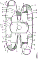
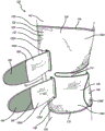
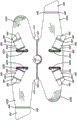
fig. 2A is a plan view of a first embodiment of a knee brace according to the present invention laid flat to expose the outer surface of the brace;
fig. 2B is a plan view of the knee brace of fig. 2A laid flat to expose the inner surface of the brace;
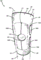
FIG. 3A is a front view of the knee brace of FIGS. 2A-2B applied to a person's leg with the base mounting straps fastened but the spider straps unfastened;
FIG. 3B is a front view of the knee brace of FIGS. 2A-2B applied to a person's leg with the base mounting strap fastened and the spider strap also fastened;
FIG. 4A is a side view of the knee brace of FIGS. 2A-2B applied to a person's leg with the base mounting straps fastened but the spider straps unfastened;
FIG. 4B is a side view of the knee brace of FIGS. 2A-2B applied to a person's leg with the base mounting strap fastened and the spider strap also fastened;
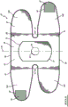
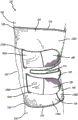
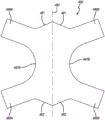
fig. 5A is a plan view of a second embodiment of a knee brace according to the present invention having a shaped tension member formed of synthetic fiber that is relatively elastic in all directions and permanently fastened to the interior surface of the base with the brace lying flat to expose the exterior surface of the brace;
fig. 5B is a plan view of the knee brace of fig. 5A laid flat to expose the inner surface of the brace;
fig. 5C is a plan view of a shaped tension member for the knee brace in fig. 5A-5B;
fig. 5D-5E are perspective views of an aperture enhancing base and backing for the knee brace of fig. 5A-5B, respectively;
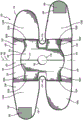
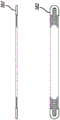
fig. 6A is a plan view of a third embodiment of a knee brace according to the present invention having upper and lower cross straps along with a resilient retainer, with the brace lying flat to expose the outer surface of the brace;
fig. 6B is a plan view of the knee brace of fig. 6A laid flat to expose the inner surface of the brace;
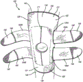
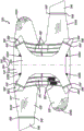
fig. 7A is a plan view of a fourth embodiment of a knee brace according to the present invention having an outer netting layer and an internally shaped tension member having both an elastic member and an inelastic member, wherein the brace lies flat to expose the outer surface of the brace;
fig. 7B is a plan view of the knee brace of fig. 7A laid flat to expose the inner surface of the brace;
FIG. 7C is a plan view of the knee brace of FIG. 7A laid flat to expose the outer surface of the brace, and with the outer mesh layer removed to reveal a configuration of an internally shaped tensioning element that can have both an elastic member and an inelastic member;
FIG. 7D is a plan view of an outer netting layer for the knee brace of FIGS. 7A-7C;
fig. 7E illustrates a resilience retention component for use in the knee brace of fig. 6A-6B, 7A-7C, and 8A-8C;
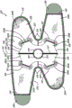
FIG. 8A is a plan view of a fifth embodiment of a knee brace according to the present invention having an outer netting layer and upper and lower cross straps that can have both an elastic portion and an inelastic portion, wherein the knee brace lies flat to expose the outer surface of the brace;
fig. 8B is a plan view of the knee brace of fig. 8A laid flat to expose the inner surface of the brace;
FIG. 8C is a plan view of the knee brace of FIG. 8A laid flat to expose the outer surface of the brace, and with the outer mesh layer removed to reveal the configuration of the upper and lower cross-straps which can have both elastic and inelastic portions; and
fig. 8D is a plan view of an outer netting layer used in the knee brace of fig. 8A-8C.
Detailed description of the invention
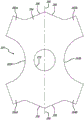
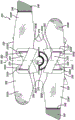
Referring to the drawings, fig. 1A and 1B show a prior art knee brace 20 of a design similar to that taught in U.S. patent No. 5472413, the contents of which are hereby incorporated by reference. The prior art knee brace 20 includes a base member 22 and a spider member 24, each made by cutting a planar sheet 26 of elastomeric material into a desired shape. The outer surface 31 of the base member 22 is preferably covered with a loop-bearing fabric 28 that adheres to the hook-type material when the loops and hook-type material are pressed together.
The base 22 of the prior art knee brace 20 has a base central portion 30 that extends vertically from an upper edge 36 to a lower edge 38, and has a central axis 40 that extends vertically downward along the mid-section of the base central portion 30. The base 22 includes a first upper mounting strap 32A, a second upper mounting strap 32B, a first lower mounting strap 34A, and a base second lower mounting strap 34B extending from the central portion 30.
Perhaps as best shown in fig. 1B, which illustrates the inner surface 39 of the base member 22, the first upper mounting strap 32A and the first lower mounting strap 34A terminate in hook-type strap fastening tabs 46, the strap fastening tabs 46 being adapted to be detachably attached to the loop-carrying fabric 28 on the outer surface 31 of the base member 22. The strap fastening tabs 46 are sewn to the mounting strap using stitches 48.
The base also has a patella opening 52 to receive the patella when the brace is worn, it can be formed to include a notch 74 to prevent bunching when the brace is worn, and the base preferably includes a trim 76, although neither of these features is required.
Perhaps as best shown in fig. 1A, which illustrates the outer surface 31 of the base 22, the prior art knee brace 20 includes a spider member 24. The spider member 24 has a spider member central portion 54 extending vertically from an upper edge 56 to a lower edge 58, and has a central axis 60 extending vertically downward along the middle of the spider member central portion 54. The spider member 24 is permanently attached to the outer surface 31 of the base 22 by stitches 72, the stitches 72 extending around the periphery of the spider member central portion 54.
The spider member 24 includes a first upper tension band 62A, a second upper tension band 62B, a first lower tension band 64A, and a second lower tension band 64B extending from the central portion 54. Each of the tension bands 62A, 62B, 64A, 64B terminates in a hook-type fastening tab 66, the fastening tab 66 being adapted to be detachably attached to the fabric 28 on the outer surface of the base 22 and sewn to the tension band with stitches 68. The spider member 24 also has a patellar opening 70 to receive the patella when the brace is worn.
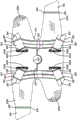
Fig. 2A and 2B show exterior and interior plan views, respectively, of a flat-lying knee brace 120 according to the present invention. The knee brace 120 includes a base component 122 and a spider component 124, each made by cutting a planar sheet 126 of elastomeric material to a desired shape. The outer surface of the base member 122 is preferably covered with a loop-bearing fabric 128 that adheres to the hook-type material when the loops and hook-type material are pressed together.
The base 122 of the knee brace 120 has a base center portion 130 that extends vertically from an upper edge 136 to a lower edge 138, and has a central axis 140 that extends vertically downward along the middle of the base center portion 130. The base 122 includes a first upper mounting strap 132A, a second upper mounting strap 132B, a first lower mounting strap 134A, and a base second lower mounting strap 134B extending from the central portion 130.
Perhaps as best shown in fig. 2B, which illustrates the inner surface 139 of the base member 122, the first upper mounting strap 132A and the first lower mounting strap 134A terminate in hook-type strap fastening tabs 146, the strap fastening tabs 146 being adapted to be detachably attached to the loop-carrying fabric 128 on the outer surface 131 of the base member 122. The hook strip fastening tab 146 is sewn to the mounting strip using stitches 148.
As best shown in fig. 4A and 4B, when the base 122 of the knee brace 120 is applied to a person's leg, the first upper mounting strap 132A overlaps the second upper mounting strap 132B at the rear of the leg, allowing the hook fastening tab 146 at the end of the first upper mounting strap 132A to adhere to the fabric 128 bearing the fiber loops on the outer surface of the second upper mounting strap 132B to fasten the knee brace 120 around the wearer's thigh 142. Similarly, the first lower mounting strap 134A overlaps and adheres to the second lower mounting strap 134B at the rear of the leg in order to fasten the knee brace 120 around the wearer's lower leg 144.
The base 122 also preferably has a patellar opening 152 to receive the patella (patella) when the brace is worn. The patella opening 152 can match the size of the patella such that the wearer's patella extends from the patella opening 152 when the brace 120 is worn, but this is not required. The patella opening 152 is preferably circular in shape, but this is not required and other shapes, such as diamond, oval, rectangular or square, may also be used. In addition to providing direct patellar stabilization, the patella opening 152 can help position the brace 120 relative to the patella during application of the brace 120.
The base 122 can be formed to include a notch 174 between the upper 132A, 132B and lower 134A, 134B mounting straps so that when the knee brace 120 is fitted over the leg, the gaps on each side form an opening at the back of the knee, but this is not required. The recess 174 may help to avoid friction, it may provide ventilation, and it may help to avoid bunching or excessive restriction of motion.
The base 122 is preferably formed as a reclosable sleeve made from a sheet of elastic material as shown in fig. 2A-2B, which provides generalized support and compression along with therapeutic warmth to the knee region, although other materials may be used. The base 122 may also be formed, for example, as a tubular elastic sleeve shaped to fit snugly around the knee and adjacent leg. The base preferably includes a trim 176, but neither of these features is required.
Perhaps as best shown in fig. 2B, which illustrates the interior surface 139 of the base 122, the knee brace 120 includes a spider member 124. The spider member 124 has a spider member central portion 154 extending vertically from an upper edge 156 to a lower edge 158, and has a central axis 160 extending vertically downward along the middle of the spider member central portion 154. The central portion 154 of the spider member 124 is permanently attached to the inner surface 139 of the base 122 by stitches 171 extending along the central axis 160 of the spider member's central portion 54.
The spider member 124 includes a first upper tension band 162A, a second upper tension band 162B, a first lower tension band 164A, and a second lower tension band 164B extending from the central portion 154. Each of the tensioning bands 162A, 162B, 164A, 164B terminates in a hook-type fastening tab 166, the fastening tab 166 being adapted to be detachably attached to the loop-carrying fabric 128 on the outer surface of the base 122 and sewn to the tensioning band with stitches 168. The spider member 124 also has a patellar opening 170 to receive the patella when the brace is worn.
While there are some similarities between the prior art knee brace 20 and the knee brace 120 according to the present invention, there are (without limitation) at least three important differences. First, the spider member 24 of the prior art knee brace 20 is fastened to the outer surface 31 of the base 22. In contrast, the spider member 124 of the knee brace 120 according to the present invention is secured to the inner surface 139 of the base 122.
Second, the spider member 24 of the prior art knee brace 20 is fastened to the base 22 by stitches 72 that extend around the periphery of the spider member center portion 54. Instead, the spider member 124 of the knee brace 120 is fastened to the base 122 by stitches 171 that extend along the central axis 160 of the spider member central portion 154.
Third, the central portion 54 of the spider member 24 and the tension bands 62A, 62B, 64A, 64B of the prior art knee brace 20 are both on the outer surface 31 of the base 22 during normal use. In contrast, in the knee brace 120, the central portion 154 of the spider member 124 is on the interior surface 139 of the base 122, and the tension bands 162A, 162B, 164A, and 164B extend through the apertures 133A, 133B, 135A, 135B to the exterior surface 131 of the base 122.
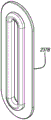
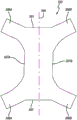
Fig. 5A-5B are plan views of a second embodiment of a knee brace 220 according to the present invention, wherein the brace is laid flat to expose the outer and inner surfaces of the brace. The knee brace 220 has a shaped tensioning member 224 (shown in isolation in fig. 5C) that is permanently fastened to the interior surface of the base. The knee brace 220 also includes a reinforcing aperture 237 that is formed with an aperture reinforcing base 237A and an aperture reinforcing backing 237B (shown in isolation in fig. 5D-5E).
The knee brace 220 includes a base component 222 and a shaped tension component 224, each made by cutting a planar sheet 226 of one or more elastomeric materials into a desired shape. The outer surface of the base member 222 is preferably covered with a loop-bearing fabric 228 that adheres to the hook-type material when the loops and hook-type material are pressed together. The shaped tension members 224 are preferably formed of synthetic fibers that are relatively elastic in all directions, such as the type known in the United states as spandex (spandex) or elastic fibers or sold under the trademark LYCRA @, although this is not a requirement and other materials may be used.
The base 222 of the knee brace 220 has a base center portion 230 that extends vertically from an upper edge 236 to a lower edge 238, and has a central axis 240 that extends vertically downward along the middle of the base center portion 230. The base 222 includes a first upper mounting strap 232A, a second upper mounting strap 232B, a first lower mounting strap 234A, and a base second lower mounting strap 234B extending from the central portion 230. The base 222 also includes a first upper aperture 233A, a second upper aperture 233B, a first lower aperture 235A, and a second lower aperture 235B, all formed as reinforcing apertures 237 in the base 222.
As perhaps best shown in fig. 5B, which illustrates the inner surface 239 of the base 222, the first upper and lower mounting straps 232A, 234A terminate in hook-type strap fastening tabs 246, the strap fastening tabs 246 being adapted to be detachably attached to the loop-carrying fabric 228 on the outer surface 231 of the base 222. The hook-type strap fastening tabs 246 are sewn to the mounting strap using stitches 248.
The knee brace 220 is applied and fastened to a person's leg in a manner similar to the knee brace 120 shown in fig. 3A-3B and 4A-4B. The base 222 also preferably has a patellar opening 252 to receive the patella (patella) when the brace is worn, and can be formed to include a lateral notch 274 between the upper and lower mounting straps 232A, 232B, 234A, 234B. The base preferably includes a trim 276, but neither of these features is required.
As perhaps best shown in fig. 5B, which illustrates the inner surface 239 of the base 222, the knee brace 220 includes a shaped tensioning member 224. As perhaps best shown in fig. 5C, the shaped tension member 224 has a central portion 254, an upper edge 256, a lower edge 258, a first lateral side 263A, a second lateral side 263B, and a central portion central axis 260. The shaped tension member 224 further includes a first upper tension band 262A, a second upper tension band 262B, a first lower tension band 264A, and a second lower tension band 264B. The shaped tension members 224 terminate in hook-type fastening tabs 266, the fastening tabs 266 being adapted to be detachably attached to the loop-carrying fabric 228 on the outer surface of the base 222 and sewn to the tension band with stitches 268. The shaped tension member 224 may include a patella opening 270 that may be permanently attached to the base 222 by a midline suture 271, the midline suture 271 extending along a central axis 260 of the central portion 254.
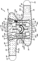
Fig. 6A-6B are plan views of a third embodiment of a knee brace 320 according to the present invention, wherein the brace is laid flat to expose the outer and inner surfaces of the brace. The knee brace 320 has resilient retainers and features upper and lower crossed elastic straps that are permanently fastened to the interior surface of the base. The knee brace 320 also includes a reinforcement aperture 337.
The knee brace 320 includes a base component 322 made by cutting a planar sheet 326 of one or more elastomeric materials into a desired shape. The outer surface 331 of the base member 322 is preferably covered with a loop-carrying fabric 328 that adheres to the hook-type material when the loops and hook-type material are pressed together. The knee brace 320 also includes an upper cross strap 324 and a lower cross strap 325, which are preferably formed of an elastic material along the length of the straps.
The base 322 of the knee brace 320 has a base center portion 330 that extends vertically from an upper edge 336 to a lower edge 338, and has a central axis 340 that extends vertically downward along the middle of the base center portion 330. The base 322 includes a first upper mounting strap 332A, a second upper mounting strap 332B, a first lower mounting strap 334A, and a base second lower mounting strap 334B extending from the central portion 330. Base 322 also includes a first upper aperture 333A, a second upper aperture 333B, a first lower aperture 335A, and a second lower aperture 335B, all formed as a reinforced aperture 337 in base 322.
Perhaps as best shown in fig. 2B showing the inner surface 339 of the base 322, the first upper mounting strap 332A and the first lower mounting strap 334A terminate in hook-type strap fastening tabs 346, the strap fastening tabs 346 being adapted to be detachably attached to the loop-carrying fabric 328 on the outer surface 331 of the base 322. The hook strip fastening tab 346 is sewn to the mounting strip using stitches 348.
The knee brace 320 is applied and fastened to a person's leg in a manner similar to the knee brace 120 shown in fig. 3A-3B and 4A-4B. The base 322 also preferably has a patellar opening 352 to receive the patella (patella) when the brace is worn, and can be formed to include a notch 374 between the upper and lower mounting straps 332A, 332B, 334A, 334B. The base preferably includes a trim 376, but neither of these features is required.
As perhaps best shown in fig. 6B, which shows the interior surface 339 of the base 322, the knee brace 320 includes an upper cross strap 324 with a central portion 354 and a lower cross strap 325 with a central portion 355. The cross-belt has a central axis 360. Upper cross belt 324 includes a first upper cross tension belt 362A and a second upper cross tension belt 362B. The lower cross belt 325 includes a first lower cross tension belt 364A and a second lower cross tension belt 364B. The tension band terminates in a hook-type Velcro (Velcro) fastening tab 366, the fastening tab 366 being adapted to be detachably attached to the loop-carrying fabric 328 on the outer surface of the base 322 and sewn to the tension band with stitching 368. The base 322 may include a patella support 370. Upper cross strap 324 and lower cross strap 325 may be permanently attached to base 322 by stitches 371 running along central axis 360 and by stitches 363A, 363B, 365A, 365B at the fixed ends of the cross straps.
The base 320 may include additional lateral support, such as one or more resilient retainers 382 (shown in fig. 7E) disposed in pockets 381 formed using additional sheets of material secured to the base by resilient retainer channel stitches 380.
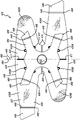
Fig. 7A-7B are plan views of a fourth embodiment of a knee brace 420 according to the present invention, wherein the brace is laid flat to expose the outer and inner surfaces of the brace. Similar to the knee brace 220 of fig. 5A-5B, the knee brace 420 has a shaped tensioning member 424 (shown in isolation in fig. 7C) that is formed of synthetic fiber that is relatively elastic in all directions and is permanently fastened to the interior surface of the base. The knee brace 420 also includes a reinforcement vent 437 and an outer mesh layer 480 (shown in isolation in fig. 7D).
The knee brace 420 includes a base component 422 and a shaped tension component 424, each made by cutting a planar sheet 226 of one or more elastomeric materials into a desired shape. The outer surface of the base member 422 is preferably covered with a loop-bearing fabric 428 that adheres to the hook-type material when the loops and hook-type material are pressed together. The shaped tension members 424 are preferably formed of synthetic fibers that are relatively elastic in all directions, such as the type known in the United states as spandex (spandex) or elastic fibers or sold under the trademark LYCRA @, although this is not required and other materials may be used.
The base 422 of the knee brace 420 has a base center portion 430 that extends vertically from an upper edge 436 to a lower edge 438, and has a central axis 440 that extends vertically downward along the middle of the base center portion 430. Base 422 includes a first upper mounting strap 432A, a second upper mounting strap 432B, a first lower mounting strap 434A, and a base second lower mounting strap 434B extending from central portion 430. The base 422 also includes a first upper aperture 433A, a second upper aperture 433B, a first lower aperture 435A and a second lower aperture 435B, all formed as a reinforcing aperture 437 in the base 422.
As perhaps best shown in fig. 7B, which shows the inner surface 439 of the base 422, the first upper mounting strip 432A and the first lower mounting strip 434A terminate in hook-type strip fastening tabs 446, the strip fastening tabs 446 being adapted to be detachably attached to the annulus fibrosus-carrying fabric 428 on the outer surface 431 of the base 422. The hook-type strap fastening tab 446 is sewn to the mounting strap using stitches 448 and may include one or more lighting devices 449, such as a reflector, a light, a glow-in-the-dark material, or a bright color.
The knee brace 420 is applied and fastened to a person's leg in a manner similar to the knee brace 120 shown in fig. 3A-3B and 4A-4B. The base 422 also preferably has a patellar opening 452 to receive the patella (patella) when the knee brace is worn. Base 422 may be formed to include a recess 474 between upper and lower mounting bands 432A, 432B, 434A, 434B. The base 422 may be formed using multiple sheets of material or may be contoured to more closely fit the leg using a simple cut with stitches 453.
As perhaps best shown in fig. 7B, which illustrates the interior surface 439 of the base 422, the knee brace 420 includes a shaped tension member 424 with a central portion 454, an upper edge 456, a lower edge 458, a first lateral side 463A, a second lateral side 463B, and a central portion central axis 460. The formed tension member 424 further includes a first upper tension band 462A, a second upper tension band 462B, a first lower tension band 464A, and a second lower tension band 464B. Perhaps as best shown in fig. 7C, the tension band may include one or more inelastic portions 465.
The shaped tension member 424 terminates in a hook-type fastening tab 466, the fastening tab 466 being adapted to be detachably attached to the loop-carrying fabric 428 on the outer surface of the base 422 and sewn to the tension band with stitches 468. The shaped tension member 424 may include a patellar opening 470 and may be permanently attached to the base 422 by a midline suture 471.
As perhaps best shown in fig. 7A, the knee brace 420 includes an outer mesh layer 480. As shown in fig. 7D, the outer mesh layer 480 has an upper edge 481, a lower edge 482, a central axis 484, a first upper arm 486A, a second upper arm 486B, a first lateral side 487A, a second lateral side 487B, a first lower arm 488A, and a second lower arm 488B. The outer web layer 480 is permanently fastened to a first upper tension belt near the first belt end, a second upper tension belt near the second belt end, a first lower tension belt near the third belt end, and a second lower tension belt 4 near the fourth belt end. The outer mesh layer 480 may additionally not be attached to the base 422.
Fig. 8A-8B are plan views of a fifth embodiment of a knee brace 520 according to the present invention, wherein the brace is laid flat to expose the outer and inner surfaces of the brace. Similar to the knee brace 320 of fig. 6A-6B, the knee brace 520 has upper and lower cross elastic straps permanently fastened to the interior surface of the base. The knee brace 520 also includes a reinforcement aperture 537 and a resilient retainer 582, and features an outer mesh layer 580 (shown in isolation in fig. 8D).
The knee brace 520 includes a base component 522 that is made by cutting a planar sheet 526 of one or more elastomeric materials into a desired shape. The outer surface of the base member 522 is preferably covered with a fabric 528 carrying loops of fiber, which adheres to the hook-type material when the loops of fiber and hook-type material are pressed together. The knee brace 520 also includes an upper cross strap 524 and a lower cross strap 525, which are preferably formed of an elastic material along the length of the straps.
The base 522 of the knee brace 520 has a base center portion 530 extending vertically from an upper edge 536 to a lower edge 538, and has a central axis 540 extending vertically downward along the middle of the base center portion 530. Base 522 includes first upper mounting strap 532A, second upper mounting strap 532B, first lower mounting strap 534A, and base second lower mounting strap 534B extending from central portion 530. The base 522 further includes a first upper orifice 533A, a second upper orifice 533B, a first lower orifice 535A, and a second lower orifice 535B, all formed as enhanced orifices 537 in the base 522.
Perhaps as best shown in fig. 8B, which shows the inner surface 539 of the base 522, the first upper mounting strap 532A and the first lower mounting strap 534A terminate in a hook-type strap fastening tab 546, the strap fastening tab 546 being adapted to be detachably attached to the loop-carrying fabric 528 on the outer surface 531 of the base 522. The hook strip fastening tab 546 is sewn to the mounting strip with stitches 548.
The knee brace 520 is applied and fastened to a person's leg in a manner similar to the knee brace 120 shown in fig. 3A-3B and 4A-4B. The base 522 also preferably has a patellar opening 552 to receive the patella (patella) when the brace is worn. Base 522 may be formed to include a recess 574 between upper and lower mounting straps 532A, 532B, 534A, 534B.
As perhaps best shown in fig. 2B, which illustrates the inner surface 539 of the base 522, the knee brace 520 includes an upper cross strap 524 with a central portion 554 and a lower cross strap 525 with a central portion 555. The cross-belt has a central axis 560. The upper cross belt 524 includes a first upper cross tension belt 562A and a second upper cross tension belt 562B. The lower cross belt 525 includes a first lower cross tension belt 564A and a second lower cross tension belt 564B. The tension band terminates in a hook-type velcro fastening tab 566, the fastening tab 566 being adapted to be detachably attached to the loop-carrying fabric 528 on the outer surface of the base 522 and sewn to the tension band with stitches 568. The base 522 may include a patella support 570. The upper and lower cross straps 524, 525 may be permanently attached to the base 522 by a midline suture 571 extending along the central axis 560 and by sutures 563A, 563B, 565A, 565B at the fixed ends of the cross straps.
The base 520 may include additional lateral support, such as one or more resilient retainers 582 disposed in a pocket 581 formed using an additional sheet of material secured to the base by resilient retainer channel stitches 580.
As perhaps best shown in fig. 8A, the knee brace 520 includes an outer mesh layer 590. As shown in fig. 8D, the outer mesh layer 590 has an upper edge 591, a lower edge 592, a central axis 594, a first upper arm 596A, a second upper arm 596B, a first lateral side 597A, a second lateral side 597B, a first lower arm 598A, and a second lower arm 598B. The outer web layer 580 is permanently fastened to a first upper tension band near the first band end, a second upper tension band near the second band end, a first lower tension band near the third band end, and a second lower tension band near the fourth band end. The outer mesh layer 590 may additionally not be attached to the base 522.
There are various possibilities regarding alternative embodiments of the knee brace according to the invention.
Although in a preferred embodiment the knee brace includes a base formed as a reclosable sleeve made from a sheet of elastic material, this is not required. For example, the base may also be formed from a tubular elastic sleeve shaped to fit snugly around the knee and adjacent leg. The base need not include a patella opening, and the patella opening (if present) may have a variety of shapes, for example, circular, square, rectangular, oval, diamond, trapezoidal, or any substantially equivalent shape. All such alternative embodiments will be referred to herein as bases.
Although in a preferred embodiment the lateral sides of the base terminate in the upper and lower fastening strips, respectively, with side notches between the upper and lower fastening strips, this is not essential. For example, the sides of the base, or portions thereof, may be straight.
Although in a preferred embodiment the base may be detachably secured around the wearer's leg using hook and loop material of the type that adheres when pressed together, this is not required. For example, other fasteners (such as buttons, clasps, buckles, pins, zippers, straps, buttons, or other substantially equivalent items) may be substituted for the hook and loop type fastener material.
While in the preferred embodiment, the various components are permanently secured together using sutures, this is not required. For example, other means (such as glue, thermal bonding or other substantially equivalent means) may be used.
One or more vertical support members may be provided on one or both sides of the base of the knee brace to provide support and protect the knee from abnormal movements, but this is not required. The vertical support members may be formed, for example, by placing the resilient retention members in elongated side pockets. The resilient retention member may comprise a flat spiral core of stainless steel or other flexible material of conventional construction commonly used in various types of braces.
For example, an elongated side pocket may be formed between vertical sewn seams that secure the side pocket cover strip to the base. The side pocket cover strips may be made of the same elastic sheet material as the base, but this is not essential. The trim may be secured to the edge of the side pocket cover strip, but this is not required.
The exact number, location and configuration of the vertical support members (if provided) may vary. For example, there may be a single elongated side pocket forming only one vertical support member, or there may be one or more elongated side pockets on each side of the knee, with a resilient retainer in each elongated side pocket. The elongated side pockets may be openable at one end to allow removal of the resilient retainer so that the brace may be washed, or so that a different resilient retainer may be inserted to adjust the amount and type of support provided. The vertical support members may comprise mechanical hinges, plastic rods, metal rods, narrow strips of reinforcement sheet material, or other substantially equivalent items, or combinations of these various alternatives.
Advantageously, the outer surface of the front portion of the knee brace according to the present invention does not carry any structure and can be smooth except for any stitches that secure the spider member to the inside of the base. For example, a smooth outer surface may be maintained to provide an attractive and clean appearance that will not impede or impede movement during use. Alternatively, other structures (such as thick knee bolsters used in contact sports such as soccer or in industries such as concrete or floor tile work or slippery materials used in sports such as volleyballs) may be positioned on the exterior surface for specific applications.
It is to be understood that the present invention is not limited to the embodiments set forth herein as illustrated, but encompasses all such forms thereof falling within the scope of the following claims.
Claims (3)
1. A knee brace, comprising:
(a) a base portion capable of being worn in close-fitting covering relation over a portion of a person's knee and an adjacent portion of a leg, the base portion including a first upper aperture, a second upper aperture, a first lower aperture, and a second lower aperture, and the base portion having an outer surface and an inner surface when worn;
(b) an upper cross belt permanently secured to an inner surface of the base, formed of a longitudinally elastic material, and including first and second upper cross tension belts,
(c) a lower cross belt permanently secured to an inner surface of the base, formed of a longitudinally elastic material, and including a first lower cross tension belt and a second lower cross tension belt,
wherein the first upper cross tension band extends through the first upper aperture to a first free band end, wherein the second upper cross tension band extends through the second upper aperture to a second band end, wherein the first lower cross tension band extends through the first lower aperture to a third band end, and wherein the second lower cross tension band extends through the second lower aperture to a fourth band end,
and wherein the first free strap end, the second strap end, the third strap end, and the fourth strap end are detachably attachable to the outer surface of the base when the brace is worn.
2. The knee brace of claim 1 further comprising an outer mesh layer permanently secured to at least one of the first upper cross tension band, the second upper cross tension band, the first lower cross tension band, and the second lower cross tension band.
3. The knee brace of claim 2 wherein the outer web layer is permanently secured to the first upper tension band proximate the first free band end, the second upper tension band proximate the second band end, the first lower tension band proximate the third band end, and the second lower tension band proximate the fourth band end.
Applications Claiming Priority (5)
| Application Number | Priority Date | Filing Date | Title |
|---|---|---|---|
| US201462016765P | 2014-06-25 | 2014-06-25 | |
| US201462016750P | 2014-06-25 | 2014-06-25 | |
| US62/016750 | 2014-06-25 | ||
| US62/016765 | 2014-06-25 | ||
| PCT/US2015/037815 WO2015200711A1 (en) | 2014-06-25 | 2015-06-25 | Knee brace |
Publications (2)
| Publication Number | Publication Date |
|---|---|
| CN106659256A CN106659256A (en) | 2017-05-10 |
| CN106659256B true CN106659256B (en) | 2020-06-23 |
Family
ID=54938825
Family Applications (1)
| Application Number | Title | Priority Date | Filing Date |
|---|---|---|---|
| CN201580045769.8A Active CN106659256B (en) | 2014-06-25 | 2015-06-25 | Knee protector |
Country Status (5)
| Country | Link |
|---|---|
| EP (1) | EP3160277B1 (en) |
| JP (1) | JP2017525860A (en) |
| CN (1) | CN106659256B (en) |
| ES (1) | ES2759601T3 (en) |
| WO (1) | WO2015200711A1 (en) |
Families Citing this family (3)
| Publication number | Priority date | Publication date | Assignee | Title |
|---|---|---|---|---|
| EP3473218B1 (en) * | 2017-10-23 | 2021-09-01 | 3M Innovative Properties Company | Area management of tissue sites on articulating joints |
| ES2722248B2 (en) * | 2018-02-07 | 2020-03-03 | Gil Francisco Javier Fernandez | Dynamic complement to protect and support the tibial plateau, kneecap and knee |
| DE102021107712A1 (en) | 2021-03-26 | 2022-09-29 | Adrian Eugen Pavel | knee pad |
Citations (3)
| Publication number | Priority date | Publication date | Assignee | Title |
|---|---|---|---|---|
| US5472413A (en) * | 1994-10-07 | 1995-12-05 | Pro Orthopedic Devices, Inc. | Universal fit knee and elbow braces with spiders |
| CN200948346Y (en) * | 2006-09-06 | 2007-09-19 | 彪仕医技股份有限公司 | Lateral supporting type kneecap guard for health caring |
| CN105208886A (en) * | 2013-03-01 | 2015-12-30 | 慕乐运动医学公司 | Knee brace |
Family Cites Families (10)
| Publication number | Priority date | Publication date | Assignee | Title |
|---|---|---|---|---|
| US3463147A (en) * | 1966-06-28 | 1969-08-26 | Frank F Stubbs | Body joint support |
| CA2089658A1 (en) * | 1990-08-17 | 1992-02-18 | E. Paul France | Patella-femoral brace |
| US6080121A (en) * | 1999-06-17 | 2000-06-27 | Becton, Dickinson And Company | Laminated orthopedic brace |
| US6402712B1 (en) * | 1999-08-16 | 2002-06-11 | Cho-Pat, Inc. | Dual action knee strap |
| US20030204156A1 (en) * | 2002-04-26 | 2003-10-30 | Nelson Ronald E. | Knee brace with patella stabilizer |
| US20040225245A1 (en) * | 2003-05-05 | 2004-11-11 | Nelson Ronald E. | Knee brace with directional elastic |
| US7708708B2 (en) * | 2004-07-22 | 2010-05-04 | Nordt Development Co., Ltd. | Donning potentiating support with expandable framework fastened to garment |
| US7882568B2 (en) * | 2006-07-19 | 2011-02-08 | Terence Fee | Two piece knee pad |
| US7959590B2 (en) * | 2007-04-19 | 2011-06-14 | New Options Sports | Method of and apparatus for patella support |
| JP5249543B2 (en) * | 2007-08-31 | 2013-07-31 | ピジョン株式会社 | Knee supporter |
-
2015
- 2015-06-25 WO PCT/US2015/037815 patent/WO2015200711A1/en active Application Filing
- 2015-06-25 JP JP2016575178A patent/JP2017525860A/en active Pending
- 2015-06-25 CN CN201580045769.8A patent/CN106659256B/en active Active
- 2015-06-25 EP EP15812726.6A patent/EP3160277B1/en active Active
- 2015-06-25 ES ES15812726T patent/ES2759601T3/en active Active
Patent Citations (3)
| Publication number | Priority date | Publication date | Assignee | Title |
|---|---|---|---|---|
| US5472413A (en) * | 1994-10-07 | 1995-12-05 | Pro Orthopedic Devices, Inc. | Universal fit knee and elbow braces with spiders |
| CN200948346Y (en) * | 2006-09-06 | 2007-09-19 | 彪仕医技股份有限公司 | Lateral supporting type kneecap guard for health caring |
| CN105208886A (en) * | 2013-03-01 | 2015-12-30 | 慕乐运动医学公司 | Knee brace |
Also Published As
| Publication number | Publication date |
|---|---|
| ES2759601T3 (en) | 2020-05-11 |
| EP3160277A4 (en) | 2018-02-14 |
| CN106659256A (en) | 2017-05-10 |
| EP3160277A1 (en) | 2017-05-03 |
| EP3160277B1 (en) | 2019-10-02 |
| WO2015200711A1 (en) | 2015-12-30 |
| JP2017525860A (en) | 2017-09-07 |
Similar Documents
| Publication | Publication Date | Title |
|---|---|---|
| US11058568B2 (en) | Knee brace | |
| US7882568B2 (en) | Two piece knee pad | |
| US11547153B2 (en) | Athletic garment with integral cup assembly | |
| EP1555971B1 (en) | Back support panel with convex surfaces for muscle support | |
| US10821015B2 (en) | Ankle brace | |
| US6065152A (en) | Athletic shin guard | |
| US10350104B2 (en) | Orthopedic brace and method of making the same | |
| US9254215B2 (en) | Knee brace | |
| US11147702B2 (en) | Elbow brace | |
| US8007454B1 (en) | Ankle support assembly and method of supporting an ankle | |
| CN106659256B (en) | Knee protector | |
| US20200100928A1 (en) | Ankle brace devices, systems, and methods | |
| US20150374528A1 (en) | Wrist brace | |
| JP2018076628A (en) | Waist supporter | |
| CN105208886B (en) | Knee-pad | |
| US9802381B2 (en) | Closure element for an abdominal belt | |
| US20160198805A1 (en) | Button cover for protection of skin and body | |
| GB2487233A (en) | Knee pad arrangements |
Legal Events
| Date | Code | Title | Description |
|---|---|---|---|
| PB01 | Publication | ||
| PB01 | Publication | ||
| SE01 | Entry into force of request for substantive examination | ||
| REG | Reference to a national code |
Ref country code: HK Ref legal event code: DE Ref document number: 1237607 Country of ref document: HK |
|
| CB02 | Change of applicant information |
Address after: Wisconsin Applicant after: Mule Sports Pharmaceutical Company Address before: Wisconsin Applicant before: Mueller Sports Medicine Inc. |
|
| CB02 | Change of applicant information | ||
| GR01 | Patent grant | ||
| GR01 | Patent grant |