JP2017523509A - Reversible connector for accessory devices - Google Patents
Reversible connector for accessory devices Download PDFInfo
- Publication number
- JP2017523509A JP2017523509A JP2016572667A JP2016572667A JP2017523509A JP 2017523509 A JP2017523509 A JP 2017523509A JP 2016572667 A JP2016572667 A JP 2016572667A JP 2016572667 A JP2016572667 A JP 2016572667A JP 2017523509 A JP2017523509 A JP 2017523509A
- Authority
- JP
- Japan
- Prior art keywords
- accessory
- computing device
- host computing
- connector
- orientation
- Prior art date
- Legal status (The legal status is an assumption and is not a legal conclusion. Google has not performed a legal analysis and makes no representation as to the accuracy of the status listed.)
- Pending
Links
Images


Classifications
-
- G—PHYSICS
- G06—COMPUTING; CALCULATING OR COUNTING
- G06F—ELECTRIC DIGITAL DATA PROCESSING
- G06F13/00—Interconnection of, or transfer of information or other signals between, memories, input/output devices or central processing units
- G06F13/38—Information transfer, e.g. on bus
- G06F13/382—Information transfer, e.g. on bus using universal interface adapter
- G06F13/387—Information transfer, e.g. on bus using universal interface adapter for adaptation of different data processing systems to different peripheral devices, e.g. protocol converters for incompatible systems, open system
-
- G—PHYSICS
- G06—COMPUTING; CALCULATING OR COUNTING
- G06F—ELECTRIC DIGITAL DATA PROCESSING
- G06F13/00—Interconnection of, or transfer of information or other signals between, memories, input/output devices or central processing units
- G06F13/10—Program control for peripheral devices
-
- G—PHYSICS
- G06—COMPUTING; CALCULATING OR COUNTING
- G06F—ELECTRIC DIGITAL DATA PROCESSING
- G06F13/00—Interconnection of, or transfer of information or other signals between, memories, input/output devices or central processing units
- G06F13/14—Handling requests for interconnection or transfer
- G06F13/20—Handling requests for interconnection or transfer for access to input/output bus
-
- G—PHYSICS
- G06—COMPUTING; CALCULATING OR COUNTING
- G06F—ELECTRIC DIGITAL DATA PROCESSING
- G06F13/00—Interconnection of, or transfer of information or other signals between, memories, input/output devices or central processing units
- G06F13/38—Information transfer, e.g. on bus
- G06F13/40—Bus structure
- G06F13/4004—Coupling between buses
- G06F13/4022—Coupling between buses using switching circuits, e.g. switching matrix, connection or expansion network
-
- G—PHYSICS
- G06—COMPUTING; CALCULATING OR COUNTING
- G06F—ELECTRIC DIGITAL DATA PROCESSING
- G06F13/00—Interconnection of, or transfer of information or other signals between, memories, input/output devices or central processing units
- G06F13/38—Information transfer, e.g. on bus
- G06F13/40—Bus structure
- G06F13/4063—Device-to-bus coupling
- G06F13/4068—Electrical coupling
- G06F13/4081—Live connection to bus, e.g. hot-plugging
-
- G—PHYSICS
- G06—COMPUTING; CALCULATING OR COUNTING
- G06F—ELECTRIC DIGITAL DATA PROCESSING
- G06F13/00—Interconnection of, or transfer of information or other signals between, memories, input/output devices or central processing units
- G06F13/38—Information transfer, e.g. on bus
- G06F13/42—Bus transfer protocol, e.g. handshake; Synchronisation
- G06F13/4282—Bus transfer protocol, e.g. handshake; Synchronisation on a serial bus, e.g. I2C bus, SPI bus
-
- G—PHYSICS
- G06—COMPUTING; CALCULATING OR COUNTING
- G06F—ELECTRIC DIGITAL DATA PROCESSING
- G06F21/00—Security arrangements for protecting computers, components thereof, programs or data against unauthorised activity
- G06F21/30—Authentication, i.e. establishing the identity or authorisation of security principals
- G06F21/31—User authentication
- G06F21/33—User authentication using certificates
Landscapes
- Engineering & Computer Science (AREA)
- Theoretical Computer Science (AREA)
- General Engineering & Computer Science (AREA)
- Physics & Mathematics (AREA)
- General Physics & Mathematics (AREA)
- Computer Hardware Design (AREA)
- Computer Security & Cryptography (AREA)
- Mathematical Physics (AREA)
- Software Systems (AREA)
- Power Sources (AREA)
- Details Of Connecting Devices For Male And Female Coupling (AREA)
- Mechanical Coupling Of Light Guides (AREA)
- Information Transfer Systems (AREA)
Abstract
アクセサリデバイスのためのリバーシブルコネクタが説明される。1以上の実施形態において、ホストコンピューティングデバイスのアクセサリのためのコネクタケーブルは、コネクタケーブルのヘッドが、いずれかの向き(ストレート又はリバース)で、ホストコンピューティングデバイスの対応するポートに挿し込まれ得るように、構成されている。ホストコンピューティングデバイスは、コネクタの割り当てられたピンに関連付けられた信号をサンプリングして、アクセサリポートへのコネクタの接続を検出し、コネクタの向きを確認するよう構成されている。ホストコンピューティングデバイスのコントローラは、コネクタの挿し込みの際にこれらの割り当てられたピンを介して伝達された信号の高値及び低値の組合せを用いて、異なるタイプのデバイスを識別し、コネクタケーブルの向きを解決することができる。次いで、ホストコンピューティングデバイスの切り替えメカニズムは、それに応じて信号を自動的にルーティングするように構成され得る。A reversible connector for an accessory device is described. In one or more embodiments, a connector cable for an accessory of a host computing device can be plugged into the corresponding port of the host computing device with the connector cable head in either orientation (straight or reverse). It is configured as such. The host computing device is configured to sample a signal associated with the assigned pin of the connector to detect the connection of the connector to the accessory port and verify the connector orientation. The host computing device controller uses the combination of the high and low values of the signal transmitted through these assigned pins when the connector is plugged in to identify different types of devices and The direction can be solved. The host computing device switching mechanism may then be configured to automatically route signals accordingly.
Description
詳細な説明が、添付の図面を参照して記載される。図面において、参照符号の最も左の数字(群)は、その参照符号が最初に現れる図面を識別するものである。説明及び図面における異なる例での同じ参照符号の使用は、類似アイテム又は同一アイテムを示し得る。図面に表されるエンティティは、1以上のエンティティを示し得るものであり、したがって、説明において、単数形のエンティティ又は複数形のエンティティが、置き換え可能に参照され得る。
概要
今日、ラップトップ及びタブレット等のモバイルコンピューティングデバイスは、様々なタイプのアクセサリデバイスをサポートし、ユニバーサルシリアルバス(USB)又は他の通信技術を用いて様々なタイプのアクセサリデバイスに接続するよう構成され得る。しかしながら、アクセサリのための従来のコネクタ、ポート、及びコネクタケーブルは、1つの向きでの接続のために設計されている。したがって、ユーザは、しばしば、間違った向きで接続しようと試みることがあり、これは、ユーザにとって苛立たしいものであるのみならず、コネクタ、ポート、及びコネクタコードに損耗及び/又は損傷をもたらし得る。
Overview Today, mobile computing devices such as laptops and tablets support various types of accessory devices and are configured to connect to various types of accessory devices using Universal Serial Bus (USB) or other communication technologies. Can be done. However, conventional connectors, ports, and connector cables for accessories are designed for connection in one orientation. Thus, users often try to connect in the wrong orientation, which is not only frustrating for the user, but can cause wear and / or damage to the connectors, ports, and connector cords.
アクセサリデバイスのためのリバーシブルコネクタ技術が説明される。1以上の実施形態において、ホストコンピューティングデバイスのアクセサリのためのコネクタケーブルは、コネクタケーブルのヘッドが、いずれかの向き(ストレート(straight)又はリバース(reverse))で、ホストコンピューティングデバイスの対応するポートに挿し込まれ得るように、構成されている。ホストコンピューティングデバイスは、コネクタの割り当てられたピンに関連付けられた信号をサンプリングして、アクセサリポートへのコネクタの接続を検出し、コネクタの向きを確認するよう構成されている。次いで、ホストコンピューティングデバイスの切り替えメカニズムは、その向きに応じて信号を自動的にルーティングするよう構成され得る。1つのアプローチにおいて、コネクタの一対の「検出」ピンが、ホットプラグ検出に専用である。ホストコンピューティングデバイスのコントローラは、コネクタの挿し込みの際にこれらの2つの検出ピンを介して伝達された、高論理状態と低論理状態との組合せを用いて、異なるタイプのデバイス(例えば、2ワイヤデバイスと1ワイヤデバイスと)を識別し、コネクタケーブルの向きを解決することができる。これらの2つの検出ピンに関連付けられたラインが、(例えば、並列に又は順に)ともにサンプリングされ得、これら2つのラインについて取得された値が、一緒に組み合わされて、デバイスのタイプ及び/又はコネクタの向きを示す組合せ(combined)論理状態が導出され得る。次いで、コントローラは、デバイスのタイプ及び向きに応じて信号ルーティングをセットアップするよう動作することができる。そうするために、コントローラは、ストレート信号経路又はリバース信号経路を適切に生じさせるように、ホスト及び/又は接続されたアクセサリのスイッチ及びマルチプレクサについての位置を指示するよう構成され得る。 A reversible connector technique for accessory devices is described. In one or more embodiments, the connector cable for the accessory of the host computing device corresponds to the host computing device with the head of the connector cable in either orientation (straight or reverse). It is configured so that it can be inserted into a port. The host computing device is configured to sample a signal associated with the assigned pin of the connector to detect the connection of the connector to the accessory port and verify the connector orientation. The host computing device switching mechanism may then be configured to automatically route the signal depending on its orientation. In one approach, a pair of “detect” pins on the connector are dedicated to hot plug detection. The controller of the host computing device uses different combinations of high and low logic states (e.g., 2) using the combination of high and low logic states communicated through these two sense pins during connector insertion. Wire device and 1-wire device) and the orientation of the connector cable can be resolved. The lines associated with these two detection pins can be sampled together (eg, in parallel or in sequence) and the values obtained for these two lines can be combined together to form the device type and / or connector A combined logic state indicating the orientation of the can be derived. The controller can then operate to set up signal routing depending on the type and orientation of the device. To do so, the controller can be configured to indicate the position of the host and / or connected accessory switches and multiplexers to properly generate a straight signal path or a reverse signal path.
以下の説明において、本明細書に記載の技術を使用することができる例示的な環境及びデバイスが最初に記載される。次いで、前記の例示的な環境において前記のデバイスによって実行され得るだけでなく、他の環境において他のデバイスによっても実行され得る例示的な手順及び詳細が説明される。したがって、前記の例示的な手順及び詳細の実装は、前記の例示的な環境/デバイスに限定されるものではなく、前記の例示的な環境/デバイスは、前記の例示的な手順及び詳細に限定されるものではない。 In the following description, exemplary environments and devices that can use the techniques described herein are first described. Exemplary procedures and details are then described that can be performed not only by the device in the exemplary environment, but also by other devices in other environments. Thus, implementation of the exemplary procedures and details is not limited to the exemplary environments / devices, and the exemplary environments / devices are limited to the exemplary procedures and details. Is not to be done.
例示的な動作環境
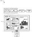
図1は、本明細書に記載の技術を使用するよう動作可能な、例示的な実装における環境100の図である。図示される環境100は、インタフェース106を介してアクセサリデバイス104に物理的に且つ通信可能に接続される例示的なホストコンピューティングデバイス102を含む。ホストコンピューティングデバイス102は、様々な態様で構成され得る。例えば、ホストコンピューティングデバイス102は、携帯電話機、図示されるタブレットコンピュータ等といった、モバイル使用のために構成され得る。したがって、ホストコンピューティングデバイス102は、十分なメモリリソース及び処理リソースを有するフルリソースデバイスから、限られたメモリリソース及び/又は処理リソースを有する低リソースデバイスに至るデバイスの形態をとることができる。ホストコンピューティングデバイス102はまた、ホストコンピューティングデバイス102に1以上の動作を実行させるソフトウェアに関連し得る。
Exemplary Operating Environment FIG. 1 is a diagram of an
ホストコンピューティングデバイス102は、例えば、入力/出力モジュール108を含むものとして図示されている。入力/出力モジュール108は、ホストコンピューティングデバイス102の入力の処理及び出力の提供に関連する機能を表す。入力デバイスのキーや、ジェスチャを識別して、アクセサリデバイス104、及び/又はディスプレイデバイス110のタッチスクリーン機能を介して認識され得るジェスチャに対応する動作を実行させるためにディスプレイデバイス110により表示される仮想キーボードのキー等に対応する機能に関連する入力等の多種多様な入力が、入力/出力モジュール108により処理され得る。したがって、入力/出力モジュール108は、キー押下、ジェスチャ等を含む入力のタイプの間の境界(division)を認識して利用することにより、多種多様な入力技術をサポートすることができる。
The host computing device 102 is illustrated as including an input /
キーボード、ゲームコントローラ、楽器を模擬するための構成、電力アダプタ、ドッキングステーション、USBハブ、外部バッテリ、これらの構成の組合せ等といった、アクセサリデバイス104についての様々な構成が意図されている。したがって、アクセサリデバイス104は、多種多様な機能をサポートするために、多種多様な構成をとることができる。異なるアクセサリデバイスが、異なる時間に、ホストコンピューティングデバイスに着脱可能に接続され得る。
Various configurations for the
前述したように、アクセサリデバイス104は、この例において、インタフェース106を介してホストコンピューティングデバイス102に物理的に且つ通信可能に接続される。異なるタイプのインタフェース106を形成するために、可撓性ヒンジ、磁気連結デバイス、一体化された通信ポート及び通信接触部材、機械的連結突出部材、スロット、及び/又はくぼみ部材を個々に又は組み合わせて使用する等、様々なタイプのインタフェース106及びコネクタが意図されている。1つの例において、インタフェース106は、対応するコネクタ及び/又はコネクタコードを介してアクセサリデバイスへの接続を可能にするよう構成されたアクセサリポート(例えば、通信ポート)を表し得る。上記で説明した技術及び以下で説明する技術に従うと、アクセサリポート及び対応するコネクタは、ポートへのコネクタのリバーシブル接続を可能にするよう設計される。少なくともいくつかの実施形態において、インタフェース106は、本明細書で説明するように、アクセサリデバイス104の認証及び制御のための通信を可能にするよう構成される。例えば、ホストコンピューティングデバイス102は、アクセサリデバイス104の存在/接続を検出したことに応じて、インタフェースを介して、アクセサリデバイスのクレデンシャル(例えば、アクセサリのアイデンティティを示すデータ)、信号、及び、能力に関する他のデータを受信することができる。インタフェースはまた、上記で説明し以下で説明するように、電力の交換と電力管理及び制御機能を実装して更新するためのメッセージの通信とのために、電力結合(power coupling)を提供することができる。
As previously mentioned,
図1にさらに示されるように、ホストコンピューティングデバイス102は、本明細書に記載の電力管理コントラクト(contract)技術の態様を実装するよう構成された電力コントローラ112を含み得る。詳細には、電力コントローラ112は、アクセサリのアイデンティティに基づいて電力管理のための設定を処理すること、ホストとアクセサリとの間の制御メッセージの交換を円滑にすること、異なる電源を管理すること及び異なる電源間で切り替えること、規定された且つ/又は選択された電力管理スキームを実装すること、バッテリ寿命を管理すること等を含む、電力管理のための様々な動作を実行する機能を表す。電力コントローラ112は、さらに、壁ソケット、外部バッテリ、電源ユニット、又は他の電源等の適切な外部電源116を介してデバイスに電力を供給するよう構成された電力アダプタ114(本明細書において電源ユニット(PSU)とも呼ばれる)との接続及び通信を円滑にすることができる。電力コントローラ112は、適切な状況においては、アクセサリデバイスにも電力を供給するよう動作可能であり得る。すなわち、電力コントローラ112は、ホストコンピューティングデバイスとアクセサリデバイスとの間の電力交換を含め、ホストコンピューティングデバイスと認可されたアクセサリデバイスとに対して一緒に、電力動作を管理することができる。
As further shown in FIG. 1, the host computing device 102 may include a
電力コントローラ112は、ハードウェア、ソフトウェア、ファームウェア、及び/又はこれらの組合せにより実装され得る。限定ではなく例として、ホストコンピューティングデバイス102は、電力コントローラ112に関連して本明細書で説明する様々な機能を実装するよう構成されたマイクロコントローラ又は他の適切なハードウェアロジックデバイスを含み得る。電力コントローラ112は、したがって、適切なハードウェアロジックデバイスに関連付けられたファームウェア又はロジックを表し得る。追加的又は代替的に、電力コントローラ112は、デバイスの処理システムとこの処理システムを介して実行可能/動作可能な1以上のプログラムモジュールとにより実装されてもよい。
The
電力アダプタ114は、複数のモードで選択的に動作し、複数の電力レベルをコンピューティングデバイスに供給するよう構成され得る。特定の時間において供給される電力のレベルは、対応するレベルの電力を電力アダプタ114に供給させるように電力コントローラ112により構成されて電力アダプタ114に送信される入力、通知、又は他の適切なフィードバックに基づき得る。電力交換状態に応じて、電力アダプタ114は、コンピューティングデバイスに接続されているときに、ホスト及びアクセサリの一方又は両方に関連付けられたバッテリを充電すること、ホスト及びアクセサリの一方又は両方の動作をサポートするために電力を供給すること、及び、ホスト及びアクセサリのジョイント充電及びジョイント動作のために外部電源116からの電力を別途供給すること、を様々な組合せで行うことができる。電力コントローラ112を介して実装される電力スキームは、アクセサリのアイデンティ、電力交換状態、電源の利用可能性等に応じて、システムコンポーネント(例えば、ホスト、アクセサリ、及びアダプタ)の間の電力のフローを制御するよう構成され得る。アクセサリデバイスのための電力管理コントラクトを実装するための電力コントローラ112及び電力アダプタ114の動作に関するさらなる詳細は、以下の説明において見出すことができる。
The power adapter 114 may be configured to selectively operate in multiple modes and provide multiple power levels to the computing device. The level of power supplied at a particular time is an input, notification, or other suitable feedback that is configured by the
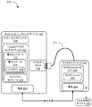
図2は、例示的なホストコンピューティングデバイス102及びアクセサリデバイス104を、概括的に200でより詳細に示している。図2において、ホストコンピューティングデバイス102は、電力コントローラ112を有するものとして示され、電力コントローラ112は、1以上のマイクロコントローラ202(マイクロ処理ユニット(μP)とも呼ばれる)により提供されるものとして示されている。ホストコンピューティングデバイス102は、1以上の内部バッテリ等の関連付けられた電源204をさらに含む。アクセサリデバイス104も、1以上のマイクロコントローラ206及びそれぞれの電源208を含み得る。電源208は、アクセサリデバイス104の内部にある1以上のバッテリ(例えば、アクセサリバッテリ)として構成され得、したがって、ホストコンピューティングデバイス102に対する外部バッテリとみなされ得る。
FIG. 2 shows an exemplary host computing device 102 and
例示的なマイクロコントローラ(μP)は、指定されたタスクの予め定められたセットを実行するよう設計されたハードウェアデバイス/システムを表す。マイクロコントローラは、処理コンポーネント、I/Oデバイス/周辺デバイス、様々なタイプのメモリ(ROM、RAM、フラッシュ、EEPROM)、プログラマブルロジック等の自己充足型(self-contained)リソースを有するそれぞれのオンチップシステム/回路を表し得る。異なるマイクロコントローラは、ハードウェアにより少なくとも部分的に実装される組み込みアプリケーション/機能を実装し、対応するタスクを実行するよう構成され得る。詳細には、例示的なマイクロコントローラ202、206は、汎用処理システムの動作外のデバイス認証及び電力管理とホストコンピューティングデバイス又はアクセサリデバイスの他のアプリケーション/コンポーネントとのためのタスクの実行を可能にする。概して、マイクロコントローラの電力消費量は、デバイスのために汎用処理システムを動作させることと比較して低い。
An exemplary microcontroller (μP) represents a hardware device / system designed to perform a predetermined set of designated tasks. Each microcontroller has a self-contained resource such as processing components, I / O devices / peripheral devices, various types of memory (ROM, RAM, flash, EEPROM), programmable logic, etc. / Represents a circuit. Different microcontrollers may be configured to implement embedded applications / functions that are implemented at least in part by hardware and perform corresponding tasks. In particular, the
したがって、マイクロコントローラを介して実装されるコンポーネントは、ホストコンピューティングデバイスの「プライマリ」処理システムを動作させることとは独立して、且つ/又は、オペレーティングシステムをブート/実行することなく若しくは他のデバイスコンポーネント及びアプリケーションを使用することなく、比較的低い電力を使用して動作することができる。すなわち、マイクロコントローラは、処理システム及び他のデバイスコンポーネント(例えば、デバイスメモリ、ネットワークインタフェース、ディスプレイデバイス等)を動作させる必要なく若しくはこれらに電力を供給する必要なく、且つ/又は、コンピューティングデバイスを完全に起動若しくはウェークアップすることなく、低電力モードで、いくつかの電力管理タスクを実行するよう動作することができる。 Thus, components implemented via a microcontroller can be independent of operating the “primary” processing system of the host computing device and / or without booting / running the operating system or other device It can operate using relatively low power without using components and applications. That is, the microcontroller does not need to operate or supply power to the processing system and other device components (eg, device memory, network interface, display device, etc.) and / or complete the computing device. Can be operated to perform some power management tasks in low power mode without wakeup or wakeup.
ホストコンピューティングデバイス102は、アクセサリポート210を介して異なるアクセサリデバイスに接続可能であり得る。アクセサリポート210は、ホストコンピューティングデバイスと様々なアクセサリとの間の物理的通信接続を実現するための機能を表す。例えば、アクセサリをホストコンピューティングデバイスに接続し、制御信号、データ、及び電力の交換を可能にするために、アクセサリポート210に対応するコネクタ211が使用され得る。図示される例において、コネクタ211は、アクセサリインタフェース210に関連付けられた対応するポートに着脱可能に挿し込まれ得るコネクタコードとして示されているが、図1に関連して説明した可撓性ヒンジ、続く図面に関連して説明するドッキングステーションへの接続、及び/又は、別の適切なインタフェースとコネクタとの組合せ等の他のタイプの接続も意図されている。本明細書に記載の技術に従うと、コネクタ211及び対応するポートは、コネクタ/ポートの組合せのリバーシブル接続/挿し込みをサポートするよう構成され得る。
Host computing device 102 may be connectable to different accessory devices via accessory port 210. Accessory port 210 represents functionality for providing physical communication connections between the host computing device and various accessories. For example, a
図2に示されるように、上記で説明した技術及び以下で説明する技術に従うと、ホストの電源204とアクセサリの電源208との間で電力交換が生じ得る。いくつかの実施形態において、電力交換は、図1に示される電力アダプタ114を介して、外部バッテリとして構成された外部電源116との間でも生じ得る。すなわち、ホストに対応するバッテリ/電源と、アクセサリインタフェースを介して接続されたアクセサリのバッテリ/電源と、外部電源と、の間で、3通りの電力交換が生じ得る。概して、ホストと、1以上の接続されたデバイス(アダプタ/アクセサリ/周辺デバイス)と、の間の電力交換は、ホストから1以上の接続されたデバイスのうちの1以上のデバイスへと且つ1以上の接続されたデバイスのうちの1以上のデバイスからホストへと行ったり来たりに(例えば、双方向に)、且つ/又は、ホストを介して、接続されたデバイス間で直接的に(例えば、デバイスからデバイスへと)、生じ得る。
As shown in FIG. 2, in accordance with the techniques described above and below, power exchange can occur between the host power supply 204 and the accessory power supply 208. In some embodiments, power exchange may also occur with an
したがって、電力交換は、いくつかのシナリオにおいて、アクセサリポート210を介して生じ得る。ホストコンピューティングデバイスに供給される電力は、ホストを動作させる(例えば、システムロードをサービスする)ために、且つ/又は、電源204(例えば、内部バッテリ)の充電レベルを維持するために、使用され得る。加えて、ホストに供給される電力は、動作をサポートするために、且つ/又は、電源208(例えば、外部バッテリ)を充電するために、アクセサリデバイス104に直接的又は間接的に供給され得る。さらに、電力は、ホストコンピューティングデバイス102及び/又はアクセサリデバイス104から、ホストコンピューティングデバイスに直接的に接続され得る、且つ/又は、図2に示されるように、アクセサリデバイス104を介してシステムに接続され得る1以上の周辺デバイス212に、分配され得る。例えば、1以上の実施形態において、アクセサリデバイスは、様々な周辺デバイス212が接続され得る複数のユニバーサルシリアルバス(USB)ポート及び/又は他のタイプの接続ポートを提供するハブ等の周辺デバイスハブの機能を提供するよう構成され得る。周辺デバイス212は、少しの例を挙げると、周辺ディスプレイデバイス、プリンタ、スキャナ、オーディオデバイス、カメラ、記憶デバイス、ネットワークアダプタ等の様々なデバイスを含み得る。
Thus, power exchange may occur via accessory port 210 in some scenarios. The power supplied to the host computing device is used to operate the host (eg, service system load) and / or to maintain the charge level of the power source 204 (eg, internal battery). obtain. In addition, power supplied to the host can be supplied directly or indirectly to the
ホストコンピューティングデバイス102及びアクセサリデバイス104の両方は、壁ソケット又は別の電源に接続されたそれぞれの電力アダプタ114の使用を介して等、外部電源116を使用するよう構成され得ることに留意されたい。それぞれの電力アダプタ114を介してアクセサリデバイス104に直接的に供給される電力は、ホストコンピューティングデバイス102に直接的に供給される電力と同等に、ホストとアクセサリとの間で、使用、共用、及び/又は交換され得る。
Note that both the host computing device 102 and the
ホストコンピューティングデバイスは、さらに、様々な形で、電力スキーム214及びセキュリティモジュール216を実装するよう構成され得る。図示される例において、電力スキーム214は、電力コントローラ112を介して実装されるものとして示されている。この例において、電力スキーム214は、ホストコンピューティングデバイス102に関連付けられるファームウェアとして構成される。例えば、電力スキーム214は、マイクロコントローラ202、電力コントローラ112、又は他の適切なハードウェアロジックデバイスに関連付けられたファームウェアを表し得る。代替的に、電力スキーム214は、ハードウェア、ソフトウェア、ファームウェア、及び/又はロジックデバイスの任意の適切な組合せを用いたスタンドアロンモジュールとして実装されてもよい。
The host computing device may be further configured to implement power scheme 214 and security module 216 in various ways. In the illustrated example, power scheme 214 is shown as implemented via
電力スキーム214は、上記で説明し以下で説明する電力管理コントラクト技術に加えて、他の電力管理機能を実装する機能を表す。詳細には、電力スキーム214は、電力アダプタ114、ホストコンピューティングデバイス112、及びアクセサリデバイス104の間の電力フローを一緒に管理するよう構成され得る。限定ではなく例として、これは、例えば、コンポーネントに関連付けられたバッテリを選択的に充電するように;バッテリ、処理システム、及びコンポーネントの間で電力を交換するように;ホスト及びアクセサリについてシステムロードをサービスするために電力を供給するように、電力フローを制御することを含み得る。そうするために、電力スキーム214は、システムの様々なコンポーネントの間の電力管理コントラクト218を確立、施行、及び更新する機能を提供することができる。この機能は、様々な態様で構成され得るシステムコンポーネント間の、電力管理に関するメッセージを送信及び受信するためのサポートを含み得る。例えば、このようなメッセージは、ホスト及びアクセサリのそれぞれのコントローラにより認識可能なパルス信号パターンとして構成され得る。少しの例を挙げると、集積回路間(I2C)プロトコル、シリアルペリフェラルインタフェース(SPI)、ユニバーサル非同期レシーバ/トランスミッタ(UART)メッセージング、パケットベースの通信、及びオブジェクトベースのメッセージを使用する等の様々な適切なメッセージングプロトコル及び対応するメッセージフォーマットが意図されている。さらに、近距離無線通信、Bluetooth(登録商標)、WiFi(登録商標)、RFIDにおいて使用されるRFプロトコル等の無線メッセージングプロトコルやセルラ通信プロトコルが使用され得る。
The power scheme 214 represents functions that implement other power management functions in addition to the power management contract techniques described above and described below. In particular, the power scheme 214 may be configured to manage the power flow between the power adapter 114, the
電力管理コントラクト218は、異なるデバイス及びシナリオのために電力交換方向及び電流制限を指定することを含むがこれに限定されない、電力管理についての動作制約を規定するよう構成される。さらに、電力管理コントラクト218についての設定は、ホスト又はアクセサリにより観測された状態に基づいて、リアルタイムに変更され得る。したがって、電力管理コントラクト218についての初期設定又はデフォルト設定は、異なるアクセサリに関連付けられ得、適切なコントラクトが、そのような異なるアクセサリの初期接続及び認可の際にアクティブ化され得る。初期にアクティブ化された電力管理コントラクト218は、その後に、システムコンポーネントのバッテリについての相対充電率(RSOC:relative states of charge)、サービスされている電力ロード、ホスト及び/又はアクセサリに接続されている周辺デバイス212の数、システムコンポーネントのための電源の利用可能性、電力供給特性、処理負荷等を含むがこれらに限定されない状態に基づいて変更され得る。したがって、アクセサリ及び/又は周辺デバイスがシステムに接続されるときに電力交換についての動作制約を固定するのではなく、本明細書に記載の電力管理コントラクトは、ホストにアクセサリが接続されている間の任意の時間における状態の変化に応じて、そのような制約に対する動的な調整を可能にするよう設計される。「リアルタイム」の状態に基づく、電力管理コントラクト218についての初期設定のそのような変更は、アクセサリデバイス及び/又はホストコンピューティングデバイスにより開始され得る。 The power management contract 218 is configured to define operational constraints for power management, including but not limited to specifying power exchange directions and current limits for different devices and scenarios. Further, the settings for the power management contract 218 may be changed in real time based on conditions observed by the host or accessory. Thus, the initial or default settings for power management contract 218 can be associated with different accessories, and the appropriate contract can be activated upon initial connection and authorization of such different accessories. The initially activated power management contract 218 is then connected to the relative states of charge (RSOC) for the battery of the system components, the serviced power load, the host and / or accessories. It can be varied based on conditions including, but not limited to, the number of peripheral devices 212, power supply availability for system components, power supply characteristics, processing load, and the like. Thus, rather than fixing operating constraints on power exchange when accessories and / or peripheral devices are connected to the system, the power management contract described herein can be used while the accessory is connected to the host. Designed to allow dynamic adjustments to such constraints in response to changes in state at any time. Such a change in the initial settings for the power management contract 218 based on a “real time” state may be initiated by the accessory device and / or the host computing device.
セキュリティモジュール216は、アクセサリデバイスがホストコンピューティングデバイスに取り付けられた/接続されたときにアクセサリデバイスを識別及び/又は認証するよう動作可能な機能を表す。セキュリティモジュール216は、多種多様な認証技術を実装するよう構成され得る。一般的に言うと、セキュリティモジュール216は、アクセサリデバイス104に関連付けられたクレデンシャル220(例えば、デバイスID/パスワード、英数字コード、識別レジスタ値等)が取得されて検証される認証シーケンスを実行する。1つのアプローチにおいて、セキュリティモジュール216は、アクセサリポートへのコネクタ211のリバーシブル接続のための技術をサポートする機能を提供するよう構成される。例えば、セキュリティモジュール216は、アクセサリポートへのコネクタの挿し込みを検出し、コネクタ211の検出ピンをサンプリングして、検出ピンについての値に応じて、コネクタの向きを、ストレートである又はリバースであるとして確認し、且つ/又は、サンプリングに基づいて、異なるタイプのデバイス及び/又は通信プロトコルを識別する、1以上のマイクロコントローラ202の機能を表し得る。異なるタイプのデバイスを識別することは、別々のRXライン及びTXラインを使用する2ワイヤデバイスと、RX/TXが単一ライン又は単一チャネル上に組み合わされる1ワイヤデバイスと、を識別することを含み得る。さらに、セキュリティモジュール216は、確認された向き及び/又はデバイスのタイプに基づいて、それに応じて信号ルーティングをセットアップする機能を表し得る。
Security module 216 represents functionality operable to identify and / or authenticate an accessory device when the accessory device is attached / connected to a host computing device. Security module 216 may be configured to implement a wide variety of authentication techniques. Generally speaking, the security module 216 performs an authentication sequence in which credentials 220 (eg, device ID / password, alphanumeric code, identification register value, etc.) associated with the
さらに、図2におけるアクセサリデバイス104は、要求時認証のためにセキュリティモジュール216に提供され得る例示的なクレデンシャル220を含むものとして示されている。クレデンシャルが正当である場合(例えば、アクセサリデバイスが、関連付けられた特権を有する認識済みのデバイスである場合)、認証は、成功であるとみなされ、アクセサリデバイス104は、電力コントローラ112を介する電力交換と、ホストコンピューティングデバイス102との他のインタラクションと、について認可され得る。さらに、クレデンシャル220は、認可されたデバイスについて保持されている電力管理コントラクト設定に関連付けられ得、したがって、認証が成功すると、異なるデバイスについてのそのような設定(例えば、初期設定又はデフォルト設定)をルックアップしてアクティブ化するために使用され得る。一方、クレデンシャルが正当ではない場合、ホストコンピューティングデバイス102とのアクセサリデバイス104のインタラクションは、様々な形で制限され得る、且つ/又は防止され得る。したがって、セキュリティモジュール216は、認可されていない且つ/又はサポートされていないデバイスが、効率的でない且つ/又は安全でないものであり得る方法で電力を供給/使用することを防止することができる。
Further, the
例示的な動作環境、システム、及びデバイスについて上記にて検討した。次いで、アクセサリデバイスのためのリバーシブルコネクタを実装するための技術に関するさらなる詳細を含む、例示的なデバイス、手順、及びシナリオについて検討する。 Exemplary operating environments, systems, and devices are discussed above. Example devices, procedures, and scenarios are then considered, including further details regarding techniques for implementing reversible connectors for accessory devices.
リバーシブルコネクタの詳細
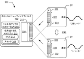
図3は、1以上の実施形態に従った、アクセサリポートへのコネクタのリバーシブル接続についての例示的なシナリオを、概括的に300で示している。この例において、ストレート向き及びリバース向きの両方におけるコネクタ211の代表図が示されている。前述したように、本明細書に記載のリバーシブルコネクタのための技術は、コネクタ211の専用検出ピンと、それらの検出ピンを介して形成される対応する回路/信号と、に依拠し得る。1つのアプローチにおいて、一対の検出ピンが、ホットプラグ検出と、デバイス認証、電力交換、信号ルーティング制御等のための通信と、をサポートするために、インタフェース106に対して使用される。インタフェース106は、異なる信号ルーティングオプション(例えば、ストレート/リバース)の間で且つ異なる通信技術(1ワイヤ/2ワイヤ)の間で切り替えるために、デバイスのタイプ及び/又はコネクタの向きに基づいて構成可能である。
Reversible Connector Details FIG. 3 shows an exemplary scenario, generally at 300, for a reversible connection of a connector to an accessory port, according to one or more embodiments. In this example, a representative view of the
ここで、ピンA302(本明細書において「HPD1A」とも呼ばれる)及びピンB304(本明細書において「HPD1B」とも呼ばれる)を含む一対の検出ピンが図示されている。一対の検出ピンが示されているが、一般的に言うと、2以上の検出ピンが、アクセサリのホットプラグ検出のために割り当てられ得、検出ピンを介して伝達された/読み取られた信号に基づく、コネクタの向き及びデバイスのタイプの解決を容易にするためにサンプリングされ得る。図示される例において、ピンA302及びピンB304が、コネクタ211のヘッドの相対する端に且つ/又はコネクタ211の相対するサイドに概して配置されるものとして示されている。異なる通信プロトコル、バス、及び高速信号をサポートするための様々な他のピン306も、コネクタ211に組み込まれる。例えば、認証/電力交換/制御のためのピンを提供することに加えて、コネクタ211は、USB、オーディオ/ビデオ信号、ディスプレイポート、ネットワーク通信等をサポートするためのピンを提供することができる。概して、これらのピンは、高速ピンペア群として配置される。ピン302、304、306は、ホストコンピューティングデバイスのアクセサリポート210に含まれる相補型ピンのセット308と嵌合するよう構成される。
Here, a pair of detection pins including pin A302 (also referred to herein as "HPD1A") and pin B304 (also referred to herein as "HPD1B") is illustrated. Although a pair of detection pins are shown, generally speaking, more than one detection pin can be assigned for accessory hot plug detection, and the signal transmitted / read via the detection pins Based on, it can be sampled to facilitate solution of connector orientation and device type. In the illustrated example,
図示される配置において、ピンA302及びピンB304は、「ストレート」向きにおいて、ホストコンピューティングデバイス102のアクセサリポート210に関連付けられたRXピン及びTXピンとそれぞれ嵌合するよう構成される。この配置において、RX信号は、ピンA302を介して伝達され得、TX信号は、ピンB304を介して伝達され得る。コネクタが、図3において示される「リバース」向きをとるように反転される又は裏返しにされると、ピンB304は、RXピンと嵌合し、ピンAは、TXピンと嵌合する。すなわち、これらのピン接続は、物理的に位置を変える。裏返しのための是正がない場合、RX/TXは、クロスしてしまうであろう。
In the illustrated arrangement,
しかしながら、ホストコンピューティングデバイスは、信号ルーティングを「適正化する」ための切り替えメカニズム310を含み得る、又は、そのような切り替えメカニズム310を利用することができる。切り替えメカニズムは、コネクタの向きにかかわらず、信号が同じエンドポイント間で効果的に通信されるように、信号のルーティングを制御するよう動作可能な機能を提供する。切り替えメカニズム310は、コネクタの向きに基づいて、且つ/又は、特定のタイプのデバイスに合わせて、システムについての信号経路を選択的に変更して、アクセサリポート及び/又は対応するインタフェースを構成するために、使用される。したがって、例えば、コネクタが、図3に示される「リバース」向きにある場合でも、切り替えメカニズム310は、依然としてRX信号がピンA302を介して伝達されるとともにTX信号がピンB304を介して伝達されるように、信号ルーティングを変更するよう動作することができる。例えば、切り替えメカニズム310は、信号経路に対する制御を可能にするための1以上のマルチプレクサ312及び/又はスイッチ314を含み得る。切り替えメカニズム310、マルチプレクサ312、及びスイッチ314が、ホストコンピューティングデバイスのコンポーネントとして図示されているが、いくつかの信号経路を選択的に切り替えるために使用されるマルチプレクサ312及びスイッチ314は、ホストコンピューティングデバイスの切り替えメカニズム310、マルチプレクサ312、及びスイッチ314に加えて、又はこれらに代えて、アクセサリデバイス140に関連付けられてもよい。この場合、ホストコンピューティングデバイス102は、ホストコンピューティングデバイスの指示の下でアクセサリの信号切り替えコンポーネントを介する信号ルーティングのセットアップを生じさせるためのコマンドを、アクセサリに送信するよう動作することができる。
However, the host computing device may include or utilize a switching mechanism 310 to “justify” signal routing. The switching mechanism provides a function operable to control the routing of signals so that signals are effectively communicated between the same endpoints regardless of the orientation of the connector. The switching mechanism 310 is configured to selectively change the signal path for the system to configure accessory ports and / or corresponding interfaces based on connector orientation and / or for particular types of devices. Used. Thus, for example, even when the connector is in the “reverse” orientation shown in FIG. 3, the switching mechanism 310 still transmits the RX signal via
図4は、コネクタ211のコネクタヘッド402についてのピンの例示に過ぎない配置の詳細を示す代表例を、概括的に400で示している。この例において、コネクタは、40個のピンを含む。ピンA304及びピンB304が、コネクタヘッド402の相対する端に且つコネクタ211の相対するサイドにあるものとして図示されている。この例において、ピンA302及びピンB304はそれぞれ、「HPD1A」及び「HPD1B」としてラベル付けされている。ラベル「HPD1A」及びラベル「HPD1B」は、本文書において、用語「ピンA」及び用語「ピンB」と置き換え可能に使用されている。例えば、USB3、USB2、電力交換等のためのピンを含む、異なるタイプの信号及びデータを伝達するための様々な他のピン306も、コネクタヘッド402内に配置されている。図3及び図4において示され説明される例示的なピン配置は、例示的な例として意図されるに過ぎず、本明細書に記載の技術に従って使用され得るピンの配置及びコネクタ構成を限定するよう意図されるものではない。アクセサリデバイスのためのリバーシブルコネクタに関連する技術に関するさらなる詳細が、以下の例示的な手順に関連して説明される。
FIG. 4 generally illustrates at 400 a representative example showing details of the placement of the
例示的な手順
以下の説明は、前述したシステム及びデバイスを使用して実施され得る技術を示している。本手順の各々の態様は、ハードウェア、ファームウェア、ソフトウェア、又はこれらの組合せにより実装され得る。本手順は、1以上のデバイスにより実行される動作を表すブロックのセットとして示されるが、必ずしも、それぞれのブロックによる動作を実行するために示される順番に限定されるものではない。以下の説明の諸部分において、図1の例示的な動作環境100及び図2〜図4の例示的なデバイス及びシナリオが参照され得る。本手順の態様は、リバーシブルコネクタ211をサポートするために1以上のマイクロコントローラ202を含む又は利用する、図2の例示的なホストコンピューティングデバイス102等の適切に構成されたコンピューティングデバイスにより実行され得る。追加的又は代替的に、本手順の態様は、1以上のマイクロコントローラ206を含む又は利用する、図2の例示的なアクセサリデバイス104等のアクセサリデバイスを介して実行されてもよい。
Exemplary Procedures The following description illustrates techniques that can be implemented using the systems and devices described above. Each aspect of the procedure may be implemented by hardware, firmware, software, or a combination thereof. The procedure is shown as a set of blocks representing operations performed by one or more devices, but is not necessarily limited to the order shown for performing the operations by each block. In the following portions of the description, reference may be made to the
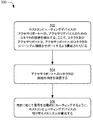
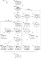
図5は、信号ルーティングが、リバーシブルコネクタの向きに応じてセットアップされる例示的な手順500を示している。ホストコンピューティングデバイスのアクセサリポートへの、アクセサリデバイスのためのコネクタの接続が検出され、ここで、コネクタ及びアクセサリポートは、アクセサリポートへのコネクタのリバーシブル接続をサポートするよう構成されている(ブロック502)。例えば、ホストコンピューティングデバイス102に関連付けられた1以上のマイクロコントローラ202は、アクセサリポート210への様々なデバイスの接続を認識するよう構成され得る。検出は、様々な形で生じ得る。1つのアプローチにおいて、1以上のマイクロコントローラ202は、コネクタ211がアクセサリインタフェース210に成功裡に取り付けられたときにアクセサリデバイスにより送信される信号を検出することができる。信号は、論理状態、電圧入力信号、パルスパターン、静的レジスタ値等を含み得る。代替的に、ホストコンピューティングデバイス102は、アクセサリポート210をポーリングして、例えば、検出ラインをモニタリングし、アクセサリに対応するレジスタ値を読み取ることにより、デバイスがアクセサリポート210に取り付けられたとき又はアクセサリポート210から取り外されたときを判定するよう構成されてもよい。取り付けは、アクセサリに関連付けられたアイデンティティ及び/又はデバイスタイプに加えて、コネクタの向きを判定するためのさらなる処理を開始させ得る。次いで、ホストとアクセサリとの間の1以上の通信インタフェース及び/又は信号ルーティングラインが、アクセサリのタイプ及びコネクタの向きに合うよう構成され得る。
FIG. 5 shows an
詳細には、アクセサリデバイスの取り付けの後、アクセサリポートへのコネクタの接続の向きが確認される(ブロック504)。向きは、様々な方法により解決され得る。概して、向きは、本明細書に記載の検出ピン上でサンプリングされた信号に基づいて判定される。コネクタの接続の際に伝達される特定の値及び/又はパターンが、デバイスのタイプに加えてコネクタの向きを示す。次いで、ホストコンピューティングデバイスの切り替えメカニズムが、向きに応じて信号を自動的にルーティングするように構成される(ブロック506)。例えば、ホストコンピューティングデバイスの1以上のマイクロコントローラ202は、コネクタ211の確認された向きに基づいて信号経路を設定するように、前述したようなやり方で切り替えメカニズム310を構成するよう動作することができる。これは、切り替えメカニズム310に関連付けられたマルチプレクサ312及びスイッチ314の位置決めを含み得る。追加的又は代替的に、マイクロコントローラ202は、アクセサリデバイス104のマイクロコントローラ206と通信して、コネクタの向きをアクセサリデバイスに通知し、且つ/又は、コネクタの向きに応じて適切な信号ルーティングをセットアップするようにアクセサリ側の切り替えメカニズムを再構成するよう、アクセサリデバイス104に指示してもよい。このようにして、信号経路についてのエンドポイントは、コネクタの向きにかかわらず、同じであり続けることができる。したがって、コンシューマは、いずれかの向き(ストレート又はリバース)のリバーシブルケーブルを介してアクセサリをホストデバイスに挿し込むことができ、システムは、向きを自動的に認識して、信号が混合されないことを確実にする。
Specifically, after the accessory device is installed, the orientation of the connector connection to the accessory port is verified (block 504). The orientation can be resolved in various ways. In general, the orientation is determined based on the signal sampled on the detection pins described herein. The particular value and / or pattern that is transmitted when the connector is connected indicates the orientation of the connector in addition to the type of device. The host computing device switching mechanism is then configured to automatically route the signal depending on the orientation (block 506). For example, one or more microcontrollers 202 of the host computing device may operate to configure the switching mechanism 310 in the manner described above to set the signal path based on the confirmed orientation of the
1以上の実施形態において、専用検出ピンが、本明細書で記載したように、ホットプラグ検出及び向きの解決のために使用され得る。検出は、検出ラインに印加される電圧(例えば、5V)と、印加された電圧に応じて取得される/読み取られる、ピンについての対応する論理状態(例えば、高(high)=1又は低(low)=0)と、に基づき得る。検出ラインについての論理状態の異なる可能な組合せは、各検出ケースがデバイスのタイプ及び/又はコネクタ211の向きに対応する検出ケースのセットに関連付けられ得る。検出ピンに関連付けられたラインが、(例えば、並列に又は順に)ともにサンプリングされ得、異なるラインについて取得された値が、一緒に組み合わされて、デバイスのタイプ及び/又はコネクタの向きを示す組合せ論理状態が導出され得る。したがって、対応する検出ケースに対する論理状態の組合せ(又は、他のクレデンシャル/アクセサリ識別子)のマッピングを反映するテーブル、ファイル、データベース、又は他のデータ構造が確立され得る。動作中、1以上のマイクロコントローラ202は、検出ピンをモニタリングし、各検出ラインについての値を取得することができる。マイクロコントローラ202は、対応する検出ケースに対する可能な論理状態の組合せのマッピングを利用して、デバイスのタイプ及びコネクタの向きを解決することができる。
In one or more embodiments, dedicated detection pins may be used for hot plug detection and orientation resolution as described herein. The detection is based on the voltage applied to the detection line (eg 5V) and the corresponding logic state (eg high = 1) or low (obtained / read in response to the applied voltage) low) = 0). Different possible combinations of logic states for the detection lines may be associated with a set of detection cases where each detection case corresponds to a device type and / or a
デバイスのタイプに関して、論理状態の組合せは、ホストが異なるタイプのデバイスを識別することを可能にするメカニズムを提供する。詳細には、検出された論理状態の組合せは、デバイスが、RXとTXとが組み合わされた単一ラインを介して通信し得る1ワイヤデバイスであるか、又は、RX及びTXについて2つの異なるラインを使用する2ワイヤデバイスであるか、を示す。1ワイヤデバイスは、基本的な電力アダプタ又は外部バッテリ等の、複雑な通信方式を使用しない、相対的に単純で低コストのデバイスであり得る。2ワイヤデバイスは、ドッキングステーション、マルチメディアアクセサリ等といった、進化したインタフェース、高速通信、及び/又は複数のタイプのデータ/プロトコルを伴う機能を提供するデバイスであり得る。 With respect to device types, the combination of logical states provides a mechanism that allows the host to identify different types of devices. Specifically, the combination of detected logic states is a one-wire device where the device can communicate via a single line with RX and TX combined, or two different lines for RX and TX. Is a two-wire device using A one-wire device can be a relatively simple and low-cost device that does not use complex communication schemes, such as a basic power adapter or an external battery. A two-wire device may be a device that provides functions with advanced interfaces, high-speed communications, and / or multiple types of data / protocols, such as docking stations, multimedia accessories, and the like.
HPD1A及びHPD1B(例えば、ピンA302及びピンB304)等の、ホットプラグ検出のために割り当てられる一対の検出ピンの場合、例えば、高−高、高−低、低−高、及び低−低といった、4つの可能な論理状態の組合せが存在する。これらの論理状態は、デバイスのタイプ(例えば、1ワイヤ又は2ワイヤ)を示し、コネクタの向きを直接的又は間接的に解決するためにも使用され得る。詳細には、接続されたアクセサリが存在しない場合には、ピンHPD1A及びHPD1Bの両方がアサートされない(例えば、低状態にある)。アクセサリデバイスがホストに接続されると、HPD1A及びHPD1Bについての状態の特定の組合せにより、アクセサリタイプが判定される。1ワイヤデバイスに関して、高状態がアサートされたラインが判定され得る。したがって、1ワイヤデバイスについての論理状態の組合せは、コネクタの向きも反映し、向きを確認するために直接的に使用され得る。2ワイヤデバイスに関して、両方のラインが高状態を有し、したがって、論理状態の組合せは、向きを解決するには不十分であり得る。したがって、2ワイヤデバイスの向きを確認するために、以下で説明するように、さらなる処理が実行され得る。
For a pair of detection pins assigned for hot plug detection, such as HPD 1A and HPD 1B (eg,
検出ピンHPD1A及びHPD1Bに関して、以下は、検出ケースに対する可能な論理状態の組合せの例示的なマッピングを示すテーブルを示している。 For detection pins HPD1A and HPD1B, the following shows a table showing an exemplary mapping of possible logic state combinations to detection cases.

例えば、1ワイヤデバイスに関して、デバイスを識別して認可するために、サンプリングが、アサートされたピン(HPD1A又はHPD1Bのいずれか)を介して実行され得る。これは、前述したように、様々な異なる認証技術を伴い得る。認証は、ホスト/マイクロコントローラが、特定のアクセサリアイデンティティに基づいて、サポートされていないアクセサリを認識し、サポートされていないアクセサリについての特定の構成情報を判定して、それに応じてインタフェース及び信号ルーティングを構成することを可能にする。例えば、アクセサリデバイスは、前述したように、様々な形で、クレデンシャル220をホストに提供するよう構成され得る。1つのアプローチにおいて、アクセサリデバイスは、ホストコンピューティングデバイスによる読み取りのために、アイデンティティを示すそれぞれのレジスタ値を公開するよう構成される。異なるレジスタ値が、異なるアクセサリに関連付けられ得る。したがって、アクセサリが接続されると、ホストコンピューティングデバイスは、対応するレジスタ値を読み取り、この値に基づいて、異なるアクセサリを識別することができる。代替的に、特定の数値コード、IDフィールド値、デバイス名等を送信する等、他のクレデンシャル220が、アクセサリのアイデンティを示すためにアクセサリによりホストに通信されてもよい。
For example, for a 1-wire device, sampling may be performed via an asserted pin (either HPD1A or HPD1B) to identify and authorize the device. This can involve a variety of different authentication techniques, as described above. Authentication allows the host / microcontroller to recognize unsupported accessories based on a specific accessory identity, determine specific configuration information about unsupported accessories, and interface and signal routing accordingly. Allows you to configure. For example, the accessory device can be configured to provide the
前述したように、取り付けられたアクセサリが2ワイヤデバイスである場合、論理状態の組合せは、向きの判定を可能にするには不十分である。この場合、向きは、認証シーケンスを通じて解決される。そうするために、サポートされている2ワイヤデバイスは、信号ラインの一方又は両方を介してクレデンシャル220をホストに提供するよう構成され得る。この場合、サンプリングは、2ワイヤデバイスを識別して認可するために、HPD1A及びHPD1Bの両方について実行され得る。1つのアプローチにおいて、2ワイヤデバイスは、1つのライン又は両方のラインに関連付けられたIDレジスタを有することができ、アイデンティティを示す1以上のレジスタ値を公開することができる。再度、他のクレデンシャル220が、アクセサリのアイデンティティを示すためにアクセサリによりホストに通信されてもよい。次いで、可能な向きケースに対する、各ラインについてのID正当性状態(例えば、正当又は不当)のマッピングに基づいて、向きが判定され得る。検出ピンHPD1A及びHPD1Bに関して、以下は、ID正当性状態向きケースの例示的なマッピングを示す例示的なテーブルを示している。
As described above, if the attached accessory is a two-wire device, the combination of logic states is not sufficient to allow orientation determination. In this case, the orientation is resolved through an authentication sequence. To do so, a supported two-wire device can be configured to provide
対応するコネクタコードを介するアクセサリの接続を検出するために、アクセサリポートがモニタリングされる(ブロック602)。モニタリングは、本明細書に記載のマイクロコントローラ202及び/又はセキュリティモジュール216により実施され得る。アクセサリポート210及びコネクタ211は、検出のために割り当てられた一対のピン(例えば、検出ピンHPD1A及びHPD1B)を有するよう構成され得る。HPD1A及びHPD1Bのいずれか一方がアサートされた(例えば、高=1という信号値)かどうかについて判定がなされる(ブロック604)。HPD1A及びHPD1Bの両方がアサートされていない場合、ブロック602において、ポートのモニタリングが続く。これらのピンのうちの少なくとも1つがアサートされた場合、両方のピンがアサートされたかどうかを判定するチェックがなされる(ブロック606)。一方のピンのみがアサートされた場合、手順600は、1ワイヤ構成に関連する動作に進み、両方のピンがアサートされた場合、手順600は、2ワイヤ構成に関連する動作に進む。
Accessory ports are monitored to detect accessory connections via corresponding connector codes (block 602). Monitoring may be performed by the microcontroller 202 and / or security module 216 described herein. Accessory port 210 and
1ワイヤ構成に関して、HPD1Aがアサートされたかどうかについて判定がなされ(ブロック608)、HPD1Aがアサートされた場合、HPD1Aがサンプリングされ(ブロック610)、識別のためのクレデンシャルが取得される。クレデンシャルに基づいて、接続されたアクセサリのIDの正当性が検証され(ブロック612)、IDが正当である場合、システムは、ストレート向きの1ワイヤに合わせて構成される(ブロック614)。一方、IDが正当ではない場合、アクセサリは、サポートされていないアクセサリであり(ブロック616)、インタラクションが制限され得る。ブロック608において、HPD1Aがアサートされていない場合、他方のピンHPD1Bが、アサートされたピンであり、サンプリングされる(ブロック618)。ここでも、IDの正当性が検証され(ブロック620)、IDが正当である場合、システムは、リバース向きの1ワイヤに合わせて構成され(ブロック622)、IDが正当ではない場合、アクセサリは、サポートされていないアクセサリであり(ブロック616)、制限され得る。 For a 1 wire configuration, a determination is made as to whether HPD1A has been asserted (block 608). If HPD1A is asserted, HPD1A is sampled (block 610) and credentials for identification are obtained. Based on the credentials, the validity of the ID of the connected accessory is verified (block 612), and if the ID is valid, the system is configured for one straight wire (block 614). On the other hand, if the ID is not valid, the accessory is an unsupported accessory (block 616) and interaction may be restricted. In block 608, if HPD1A is not asserted, the other pin HPD1B is the asserted pin and is sampled (block 618). Again, the validity of the ID is verified (block 620), and if the ID is valid, the system is configured for one reverse-facing wire (block 622), and if the ID is not valid, the accessory Unsupported accessory (block 616) and may be limited.
2ワイヤ構成に関して、HPD1A及びHPD1Bの両方がサンプリングされる(ブロック624)。HPD1AについてIDの正当性が検証され(ブロック626)、HPD1A上でサンプリングされたIDが正当である場合、次いで、HPD1BについてIDの正当性が検証される(ブロック628)。HPD1A及びHPD1Bの両方についてのIDが正当である場合、ストレート向き及びリバース向きの両方がサポートされており、アプリケーションに基づいて構成が行われる(ブロック630)。一方、HPD1AについてのIDのみが正当である場合、システムは、ストレート向きの2ワイヤに合わせて構成される(ブロック632)。ブロック626において、HPD1AについてのIDが正当ではない場合、HPD1BについてIDの正当性が検証される(ブロック634)。ブロック634において、HPD1BについてのIDが正当である場合、システムは、リバース向きの2ワイヤに合わせて構成される(ブロック636)。一方、HPD1A及びHPD1Bの両方についてサンプリングされたIDが不当である場合、アクセサリは、サポートされていないアクセサリであり(ブロック638)、制限され得る。示されたロジックに基づいてシステムが適切に構成された後、適用された構成を用いて、信号がルーティングされる(ブロック640)。
For the two-wire configuration, both HPD 1A and HPD 1B are sampled (block 624). The validity of the ID is verified for HPD 1A (block 626), and if the ID sampled on HPD 1A is valid, then the validity of the ID is verified for HPD 1B (block 628). If the IDs for both HPD 1A and HPD 1B are valid, both straight and reverse orientations are supported and configuration is done based on the application (block 630). On the other hand, if only the ID for HPD 1A is valid, the system is configured for two straight wires (block 632). In
例示的な手順600は、ソフトウェア、ファームウェア、ハードウェア、又はこれらの何らかの組合せにより実装され得る。ソフトウェア実装又はファームウェア実装は、有利なことに、フレキシブルであり、ソフトウェア更新又はファームウェア更新により再構成され得る。代替的に、例示的な手順600は、ディスクリート論理ゲートと、アナログ−デジタル回路を含むアナログ及び混合信号回路と、を使用して実装されてもよい。この代替は、有利なことに、より高速であり、例えば、レジスタ値を決定するためのプログラム可能な閾値を含み得る。この決定の二値性のため、デジタルロジックが、拡張的に使用され得る。
The
例示的な手順について上記にて検討した。次いで、1以上の実施形態における、リバーシブルコネクタ技術の態様を実装するために使用され得る例示的なシステム及びデバイスについて検討する。 Exemplary procedures are discussed above. Next, exemplary systems and devices that can be used to implement aspects of reversible connector technology in one or more embodiments are discussed.
例示的なシステム及びデバイス
図7は、本明細書に記載の様々な技術を実装することができる1以上のコンピューティングシステム及び/又はコンピューティングデバイスを表す例示的なコンピューティングデバイス702を含む例示的なシステムを、概括的に700で示している。コンピューティングデバイス702は、例えば、ユーザの片手又は両手で把持されて運ばれるように形成されたサイズのハウジングを使用することによりモバイル構成をとるよう構成され得る。そのようなモバイル構成の例は、携帯電話機、モバイルゲーム及び音楽デバイス、並びにタブレットコンピュータを含むが、他の例も意図されている。
Exemplary Systems and Devices FIG. 7 includes an exemplary computing device 702 that represents one or more computing systems and / or computing devices that can implement various techniques described herein. Such a system is generally indicated at 700. The computing device 702 may be configured to take a mobile configuration, for example, by using a housing sized to be held and carried by the user's one or both hands. Examples of such mobile configurations include mobile phones, mobile games and music devices, and tablet computers, although other examples are contemplated.
図示される例示的なコンピューティングデバイス702は、処理システム704、1以上のコンピュータ読み取り可能な媒体706、及び1以上の入力/出力(I/O)インタフェース708を含み、これらは、互いに通信可能に接続される。図示されていないが、コンピューティングデバイス702は、様々なコンポーネントを互いと接続するシステムバス又は他のデータ・コマンド転送システムをさらに含み得る。システムバスは、メモリバス若しくはメモリコントローラ、周辺バス、ユニバーサルシリアルバス、及び/又は、様々なバスアーキテクチャのうちのいずれかを利用するプロセッサバス若しくはローカルバス等の様々なバス構造の任意の1つ又は組合せを含み得る。制御ライン及びデータライン等の多様な他の例も意図されている。
The illustrated exemplary computing device 702 includes a
処理システム704は、ハードウェアを用いて1以上の動作を実行する機能を表す。したがって、処理システム704は、プロセッサ、機能ブロック等として構成され得るハードウェア要素710を含むものとして図示されている。これは、特定用途向け集積回路、又は、1以上の半導体を用いて形成される他のロジックデバイスとしてのハードウェアによる実装物を含み得る。ハードウェア要素710は、ハードウェア要素710が形成される材料又はハードウェア要素710において利用される処理機構により限定されるものではない。例えば、プロセッサは、1以上の半導体及び/又はトランジスタ(例えば、電子集積回路(IC))から構成され得る。そのようなコンテキストにおいて、プロセッサ実行可能な命令は、電子的に実行可能な命令であり得る。
The
コンピュータ読み取り可能な記憶媒体706は、メモリ/ストレージ712を含むものとして図示されている。メモリ/ストレージ712は、1以上のコンピュータ読み取り可能な媒体に関連付けられたメモリ/ストレージ能力を表す。メモリ/ストレージコンポーネント712は、揮発性媒体(ランダムアクセスメモリ(RAM)等)及び/又は不揮発性媒体(読み取り専用メモリ(ROM)、フラッシュメモリ、光ディスク、磁気ディスク等)を含み得る。メモリ/ストレージコンポーネント712は、固定媒体(例えば、RAM、ROM、固定ハードドライブ等)に加えて、着脱可能な媒体(例えば、フラッシュメモリ、着脱可能なハードドライブ、光ディスク等)を含み得る。コンピュータ読み取り可能な媒体706は、以下でさらに説明するように、多様な他の態様で構成され得る。 Computer readable storage media 706 is illustrated as including memory / storage 712. Memory / storage 712 represents memory / storage capabilities associated with one or more computer-readable media. Memory / storage component 712 may include volatile media (such as random access memory (RAM)) and / or non-volatile media (such as read only memory (ROM), flash memory, optical disk, magnetic disk, etc.). The memory / storage component 712 may include removable media (eg, flash memory, removable hard drive, optical disc, etc.) in addition to fixed media (eg, RAM, ROM, fixed hard drive, etc.). The computer readable medium 706 may be configured in a variety of other ways, as further described below.
1以上の入力/出力インタフェース708は、様々な入力デバイスを用いてユーザがコマンド及び情報をコンピューティングデバイス702に入力できるようにするとともに、様々な出力デバイスを用いて情報をユーザ及び/又は他のコンポーネントに提示できるようにする機能を表す。入力デバイスの例は、キーボード、カーソル制御デバイス(例えば、マウス)、マイクロフォン、スキャナ、タッチ機能(例えば、物理的タッチを検出するよう構成される静電容量式センサ又は他のセンサ)、(例えば、タッチを含まない、ジェスチャとしての動きを認識するために、赤外線周波数等の非可視波長又は可視波長を利用することができる)カメラ等を含む。出力デバイスの例は、ディスプレイデバイス(例えば、モニタやプロジェクタ)、スピーカ、プリンタ、ネットワークカード、触覚応答デバイス等を含む。したがって、コンピューティングデバイス702は、ユーザインタラクションをサポートするために、以下でさらに説明するように、多様な態様で構成され得る。 One or more input / output interfaces 708 allow a user to enter commands and information into the computing device 702 using a variety of input devices and provide information to the user and / or other devices using a variety of output devices. Represents a function that can be presented to a component. Examples of input devices include keyboards, cursor control devices (eg, mice), microphones, scanners, touch functions (eg, capacitive sensors or other sensors configured to detect physical touches), (eg, In order to recognize movement as a gesture that does not include touch, a non-visible wavelength such as an infrared frequency or a visible wavelength can be used). Examples of output devices include display devices (eg, monitors and projectors), speakers, printers, network cards, tactile response devices, and the like. Accordingly, the computing device 702 can be configured in a variety of ways to support user interaction, as described further below.
コンピューティングデバイス702は、さらに、コンピューティングデバイス702から物理的に且つ通信可能に着脱可能であるアクセサリデバイス714に物理的に且つ通信可能に接続されるものとして図示されている。このように、多種多様な入力デバイスが、多種多様な機能をサポートするための多種多様な構成を有するコンピューティングデバイス702に接続され得る。この例において、アクセサリデバイス714は、圧力検知式キー、機械的切り替えキー、ボタン等として構成され得る1以上のコントロール716を含む。 The computing device 702 is further illustrated as being physically and communicatively connected to an accessory device 714 that is physically and communicatively removable from the computing device 702. In this way, a wide variety of input devices can be connected to a computing device 702 that has a wide variety of configurations to support a wide variety of functions. In this example, accessory device 714 includes one or more controls 716 that can be configured as pressure sensitive keys, mechanical switching keys, buttons, and the like.
アクセサリデバイス714は、さらに、様々な機能をサポートするよう構成され得る1以上のモジュール718を含むものとして図示されている。1以上のモジュール718は、例えば、コントロール716から受信されたアナログ信号及び/又はデジタル信号を処理して、入力が意図されたものであるかどうかを判定したり、入力が静圧を示すかどうかを判定したり、コンピューティングデバイス702に対する動作のためにアクセサリデバイス714の認証をサポートしたりするよう構成され得る。 The accessory device 714 is further illustrated as including one or more modules 718 that can be configured to support various functions. One or more modules 718 may, for example, process analog and / or digital signals received from control 716 to determine whether the input is intended or whether the input indicates static pressure. Or supporting authentication of the accessory device 714 for operation on the computing device 702.
様々な技術が、ソフトウェア、ハードウェア要素、又はプログラムモジュールの一般的コンテキストにおいて本明細書で説明され得る。一般に、そのようなモジュールは、特定のタスクを実行する又は特定の抽象データ型を実装するルーチン、プログラム、オブジェクト、要素、コンポーネント、データ構造等を含む。本明細書で使用される「モジュール」、「機能」、及び「コンポーネント」という用語は、一般に、ソフトウェア、ファームウェア、ハードウェア、又はこれらの組合せを表す。本明細書に記載の技術の特徴は、プラットフォーム非依存であり、これは、そのような技術が、様々なプロセッサを有する様々な商用コンピューティングプラットフォーム上で実装され得ることを意味する。 Various techniques may be described herein in the general context of software, hardware elements, or program modules. In general, such modules include routines, programs, objects, elements, components, data structures, etc. that perform particular tasks or implement particular abstract data types. The terms “module”, “function”, and “component” as used herein generally represent software, firmware, hardware, or a combination thereof. Features of the technology described herein are platform independent, meaning that such technology can be implemented on a variety of commercial computing platforms having a variety of processors.
説明したモジュール及び技術の実装物は、何らかの形態のコンピュータ読み取り可能な媒体に記憶されてもよいし、何らかの形態のコンピュータ読み取り可能な媒体を介して伝送されてもよい。コンピュータ読み取り可能な媒体は、コンピューティングデバイス1002がアクセスできる様々な媒体を含み得る。限定ではなく例として、コンピュータ読み取り可能な媒体は、「コンピュータ読み取り可能な記憶媒体」及び「コンピュータ読み取り可能な信号媒体」を含み得る。 The implementations of the modules and techniques described may be stored on some form of computer readable media or transmitted over some form of computer readable media. Computer readable media can include a variety of media that can be accessed by computing device 1002. By way of example, and not limitation, computer readable media may include “computer readable storage media” and “computer readable signal media”.
「コンピュータ読み取り可能な記憶媒体」は、単なる信号伝送、搬送波、又は信号自体ではなく、情報の記憶を可能にする媒体及び/若しくはデバイスを指し得る。したがって、コンピュータ読み取り可能な記憶媒体は、信号自体又は信号伝送媒体を含まない。コンピュータ読み取り可能な記憶媒体は、コンピュータ読み取り可能な命令、データ構造、プログラムモジュール、論理素子/回路、又は他のデータといった情報を記憶するのに適した方法又は技術により実装された、揮発性及び不揮発性の着脱可能及び着脱不可能な媒体及び/又は記憶デバイス等のハードウェアを含む。コンピュータ読み取り可能な記憶媒体の例は、RAM、ROM、EEPROM、フラッシュメモリ、若しくは他のメモリ技術、CD−ROM、デジタル多用途ディスク(DVD)、若しくは他の光ストレージ、ハードディスク、磁気カセット、磁気テープ、磁気ディスクストレージ、若しくは他の磁気記憶デバイス、又は、所望の情報を記憶するのに適した、コンピュータがアクセスできる他の記憶デバイス、有体の媒体、若しくは製品を含み得るが、これらに限定されるものではない。 “Computer-readable storage media” can refer to media and / or devices that enable storage of information rather than just signal transmission, carrier waves, or the signals themselves. Thus, a computer readable storage medium does not include the signal itself or a signal transmission medium. Computer-readable storage media can be volatile and non-volatile, implemented in any suitable manner or technique for storing information such as computer-readable instructions, data structures, program modules, logic elements / circuits, or other data. Hardware such as removable and non-removable media and / or storage devices. Examples of computer readable storage media are RAM, ROM, EEPROM, flash memory, or other memory technology, CD-ROM, digital versatile disc (DVD), or other optical storage, hard disk, magnetic cassette, magnetic tape , Magnetic disk storage, or other magnetic storage devices, or other storage devices, tangible media, or products accessible by a computer that are suitable for storing the desired information. It is not something.
「コンピュータ読み取り可能な信号媒体」は、ネットワークを介して等、コンピューティングデバイス702のハードウェアに命令を伝送するよう構成された信号伝送媒体を指し得る。信号媒体は、通常、コンピュータ読み取り可能な命令、データ構造、プログラムモジュール、又は他のデータを、搬送波、データ信号、又は他の伝送機構等の変調されたデータ信号内に具現化することができる。信号媒体はまた、任意の情報配信媒体を含む。「変調されたデータ信号」という用語は、信号内の情報を符号化するように設定又は変更された特性のうちの1以上を有する信号を意味する。限定ではなく例として、通信媒体は、有線ネットワーク又は直接配線接続等の有線媒体と、音響、RF、赤外線、及び他の無線媒体等の無線媒体と、を含む。 A “computer-readable signal medium” may refer to a signal transmission medium configured to transmit instructions to the hardware of the computing device 702, such as over a network. A signal medium typically can embody computer readable instructions, data structures, program modules, or other data in a modulated data signal, such as carrier wave, data signal, or other transport mechanism. The signal medium also includes any information distribution medium. The term “modulated data signal” means a signal that has one or more of its characteristics set or changed in such a manner as to encode information in the signal. By way of example, and not limitation, communication media includes wired media such as a wired network or direct-wired connection, and wireless media such as acoustic, RF, infrared, and other wireless media.
前述したように、ハードウェア要素710及びコンピュータ読み取り可能な媒体706は、1以上の命令を実行する等の、本明細書に記載の技術の少なくとも一部の態様を実装するためにいくつかの実施形態において使用することができる、ハードウェア形態で実装されたモジュール、プログラマブルデバイスロジック、及び/又は固定デバイスロジックを表す。ハードウェアは、集積回路又はオンチップシステム、マイクロコントローラデバイス、特定用途向け集積回路(ASIC)、フィールドプログラマブルゲートアレイ(FPGA)、コンプレックスプログラマブルロジックデバイス(CPLD)、及び、シリコンによる他の実装物又は他のハードウェアデバイスのコンポーネントを含み得る。このコンテキストにおいて、ハードウェアは、そのハードウェアにより具現化される命令及び/又はロジックにより定められるプログラムタスクを実行する処理デバイスに加えて、例えば前述したコンピュータ読み取り可能な記憶媒体等の、実行される命令を記憶するために利用されるハードウェアとして動作することができる。
As previously mentioned, the
前述したものの組合せを使用して、本明細書に記載の様々な技術を実装することもできる。したがって、ソフトウェア、ハードウェア、又は、実行可能なモジュールは、何らかの形態のコンピュータ読み取り可能な記憶媒体上に具現化される、且つ/又は、1以上のハードウェア要素710により具現化される1以上の命令及び/又はロジックとして実装され得る。コンピューティングデバイス702は、ソフトウェアモジュール及び/又はハードウェアモジュールに対応する特定の命令及び/又は機能を実行するよう構成され得る。したがって、ソフトウェアとしてコンピューティングデバイス702により実行可能なモジュールの実装は、例えば、処理システム704のハードウェア要素710及び/又はコンピュータ読み取り可能な記憶媒体を使用することにより、ハードウェアにより少なくとも部分的に実現され得る。命令及び/又は機能は、本明細書に記載の技術、モジュール、及び例を実装する1以上の製品(例えば、1以上のコンピューティングデバイス702及び/又は処理システム704)により、実行可能/動作可能であり得る。
Combinations of the foregoing can also be used to implement the various techniques described herein. Accordingly, software, hardware, or executable modules may be embodied on some form of computer readable storage media and / or embodied by one or
結び
例示的な実施形態が、構造的特徴及び/又は方法的動作に特有の言葉で説明されたが、特許請求の範囲において定められる実施形態は、上述した特定の特徴又は動作に必ずしも限定されるものではない。そうではなく、特定の特徴及び動作は、特許請求される特徴を実施する例示的な形態として開示されている。
Although exemplary embodiments have been described in language specific to structural features and / or methodological operations, the embodiments defined in the claims are not necessarily limited to the specific features or operations described above. It is not a thing. Rather, the specific features and acts are disclosed as exemplary forms of implementing the claimed features.
Claims (15)
前記ホストコンピューティングデバイスのポートへのコネクタの接続を、前記コネクタにおいて割り当てられた一対の検出ピンを介して伝達された信号に基づいて検出する検出ステップと、
前記信号に基づいて、前記ポートへの前記コネクタの前記接続の向きを確認する確認ステップであって、前記信号は、前記一対の検出ピンについての論理状態の組合せを示す、確認ステップと、
前記の確認された向き及び前記論理状態の組合せに応じて信号をルーティングするように、前記ホストコンピューティングデバイスの切り替えメカニズムを構成する構成ステップと、
を含む方法。 A method performed by a host computing device, comprising:
Detecting a connection of a connector to a port of the host computing device based on signals communicated via a pair of detection pins assigned at the connector;
A confirmation step of confirming the orientation of the connection of the connector to the port based on the signal, wherein the signal indicates a combination of logic states for the pair of detection pins;
Configuring a switching mechanism of the host computing device to route signals in response to the combination of the identified orientation and the logic state;
Including methods.
前記一対の検出ピンを介して伝達された前記信号をともにサンプリングするステップと、
前記一対の検出ピンを介して取得された値を組み合わせて、前記論理状態の組合せを導出するステップと、
を含む、請求項1記載の方法。 The detecting step includes
Sampling together the signals transmitted through the pair of detection pins;
Combining values obtained via the pair of detection pins to derive a combination of the logic states;
The method of claim 1 comprising:
前記コネクタの割り当てられた検出ピンに関連付けられた信号をサンプリングして、アクセサリデバイスのデバイスタイプを、1ワイヤデバイス又は2ワイヤデバイスとして判定するステップと、
前記デバイスタイプが前記1ワイヤデバイスである場合、前記のサンプリングされた信号から直接的に、前記接続の前記向きを判定するステップと、
前記デバイスタイプが前記2ワイヤデバイスである場合、前記アクセサリデバイスにより提供されたクレデンシャルを使用して、前記向きを示す前記検出ピンについての正当性状態を確立する認証シーケンスを通じて、前記向きを解決するステップと、
を含む、請求項1記載の方法。 The confirmation step includes
Sampling a signal associated with an assigned detection pin of the connector to determine a device type of the accessory device as a one-wire device or a two-wire device;
Determining the orientation of the connection directly from the sampled signal if the device type is the one-wire device;
If the device type is the two-wire device, resolving the orientation through an authentication sequence that establishes a legitimacy state for the detection pin indicating the orientation using credentials provided by the accessory device When,
The method of claim 1 comprising:
1以上のマイクロコントローラと、
アクセサリデバイスのためのコネクタに接続可能なアクセサリポートと、
命令を記憶している1以上のコンピュータ読み取り可能な媒体であって、前記命令が、前記1以上のマイクロコントローラにより実行されたときに、前記命令は、前記ホストコンピューティングデバイスに、
前記コネクタに組み込まれた一対の検出ピンを介して、前記アクセサリポートへの前記コネクタの挿し込みを検出する動作と、
前記一対の検出ピンを介して伝達された、高論理状態と低論理状態との論理状態の組合せを取得する動作と、
前記論理状態の組合せに基づいて、前記アクセサリデバイスのデバイスタイプを、1ワイヤデバイス又は2ワイヤデバイスとして判定する判定動作と、
前記アクセサリポートに挿し込まれた前記コネクタの向きを確認する確認動作であって、
前記デバイスタイプが前記1ワイヤデバイスである場合、前記論理状態の組合せから直接的に、前記向きを判定する動作と、
前記デバイスタイプが前記2ワイヤデバイスである場合、前記一対の検出ピンを介して前記アクセサリデバイスの1以上のアイデンティティレジスタのレジスタ値をサンプリングして、前記向きを示す正当性状態を確立する動作と、
を含む確認動作と、
前記デバイスタイプ及び前記の確認された向きに応じて信号ルーティングをセットアップするセットアップ動作と、
を含む複数の動作を実行させる、1以上のコンピュータ読み取り可能な媒体と、
を備えたホストコンピューティングデバイス。 A host computing device,
One or more microcontrollers;
An accessory port that can be connected to a connector for an accessory device;
One or more computer-readable media storing instructions, wherein when the instructions are executed by the one or more microcontrollers, the instructions are transmitted to the host computing device;
Detecting the insertion of the connector into the accessory port via a pair of detection pins built into the connector;
An operation of obtaining a combination of a logic state of a high logic state and a low logic state transmitted through the pair of detection pins;
A determination operation for determining a device type of the accessory device as a one-wire device or a two-wire device based on the combination of the logic states;
Confirmation operation for confirming the orientation of the connector inserted into the accessory port,
When the device type is the one-wire device, an operation for determining the orientation directly from the combination of the logic states;
If the device type is the two-wire device, sampling a register value of one or more identity registers of the accessory device via the pair of detection pins to establish a legitimacy state indicating the orientation;
Confirmation operation including
A setup operation to set up signal routing according to the device type and the confirmed orientation;
One or more computer-readable media for performing a plurality of operations including:
A host computing device equipped with.
Applications Claiming Priority (3)
| Application Number | Priority Date | Filing Date | Title |
|---|---|---|---|
| US14/304,174 US9367490B2 (en) | 2014-06-13 | 2014-06-13 | Reversible connector for accessory devices |
| US14/304,174 | 2014-06-13 | ||
| PCT/US2015/035218 WO2015191790A2 (en) | 2014-06-13 | 2015-06-11 | Reversible connector for accessory devices |
Publications (2)
| Publication Number | Publication Date |
|---|---|
| JP2017523509A true JP2017523509A (en) | 2017-08-17 |
| JP2017523509A5 JP2017523509A5 (en) | 2018-06-14 |
Family
ID=54548232
Family Applications (1)
| Application Number | Title | Priority Date | Filing Date |
|---|---|---|---|
| JP2016572667A Pending JP2017523509A (en) | 2014-06-13 | 2015-06-11 | Reversible connector for accessory devices |
Country Status (11)
| Country | Link |
|---|---|
| US (2) | US9367490B2 (en) |
| EP (1) | EP3155697B1 (en) |
| JP (1) | JP2017523509A (en) |
| KR (1) | KR102380100B1 (en) |
| CN (1) | CN106462515B (en) |
| AU (1) | AU2015274582B2 (en) |
| BR (1) | BR112016028044B1 (en) |
| CA (1) | CA2948655C (en) |
| MX (1) | MX366782B (en) |
| RU (1) | RU2682911C2 (en) |
| WO (1) | WO2015191790A2 (en) |
Families Citing this family (43)
| Publication number | Priority date | Publication date | Assignee | Title |
|---|---|---|---|---|
| US9634855B2 (en) | 2010-05-13 | 2017-04-25 | Alexander Poltorak | Electronic personal interactive device that determines topics of interest using a conversational agent |
| KR101967631B1 (en) * | 2012-06-19 | 2019-04-11 | 삼성전자주식회사 | Docking station |
| US10111099B2 (en) | 2014-05-12 | 2018-10-23 | Microsoft Technology Licensing, Llc | Distributing content in managed wireless distribution networks |
| US9384335B2 (en) | 2014-05-12 | 2016-07-05 | Microsoft Technology Licensing, Llc | Content delivery prioritization in managed wireless distribution networks |
| US9384334B2 (en) | 2014-05-12 | 2016-07-05 | Microsoft Technology Licensing, Llc | Content discovery in managed wireless distribution networks |
| US9430667B2 (en) | 2014-05-12 | 2016-08-30 | Microsoft Technology Licensing, Llc | Managed wireless distribution network |
| US9874914B2 (en) | 2014-05-19 | 2018-01-23 | Microsoft Technology Licensing, Llc | Power management contracts for accessory devices |
| US10037202B2 (en) | 2014-06-03 | 2018-07-31 | Microsoft Technology Licensing, Llc | Techniques to isolating a portion of an online computing service |
| US9367490B2 (en) | 2014-06-13 | 2016-06-14 | Microsoft Technology Licensing, Llc | Reversible connector for accessory devices |
| US9717006B2 (en) | 2014-06-23 | 2017-07-25 | Microsoft Technology Licensing, Llc | Device quarantine in a wireless network |
| US10320128B2 (en) | 2014-11-19 | 2019-06-11 | Dell Products L.P. | Information handling system multi-purpose connector guide pin structure |
| US9791906B2 (en) | 2014-11-19 | 2017-10-17 | Dell Products L.P. | Information handling system multi-purpose connector guide pin structure |
| US9891680B2 (en) * | 2014-11-19 | 2018-02-13 | Dell Products L.P. | Information handling system multi-purpose connector guide pin structure |
| TWI571746B (en) * | 2015-05-13 | 2017-02-21 | 聯陽半導體股份有限公司 | Data transmission system and transmission method thereof |
| US9811483B2 (en) * | 2015-06-19 | 2017-11-07 | Texas Instruments Incorporated | Configurable serial communication hub |
| US20160378632A1 (en) * | 2015-06-26 | 2016-12-29 | Intel Corporation | Port selection at a computing device |
| US10088514B2 (en) * | 2015-06-30 | 2018-10-02 | Intel Corporation | Orientation indicator with pin signal alteration |
| US20170075851A1 (en) * | 2015-09-16 | 2017-03-16 | Uniwill Technology Company | Multifunction expansion module |
| TWI593292B (en) * | 2015-11-13 | 2017-07-21 | 晨星半導體股份有限公司 | Multimedia communication apparatus and control method for audio and video transmission over standard cable |
| US20190148898A1 (en) * | 2016-04-28 | 2019-05-16 | Hewlett-Packard Development Company, L.P. | Connector orientations |
| EP3264279A1 (en) | 2016-06-28 | 2018-01-03 | Thomson Licensing | Switch for reversible interface |
| WO2018005855A1 (en) * | 2016-06-29 | 2018-01-04 | University Of Massachusetts | Systems, devices, and methods for providing power-proportional communication |
| GB2552559A (en) * | 2016-07-25 | 2018-01-31 | Cirrus Logic Int Semiconductor Ltd | Connectors for data transfer |
| KR102575430B1 (en) | 2016-10-25 | 2023-09-06 | 삼성전자 주식회사 | Electronic device and method for recognizing connected terminals of external device thereof |
| JP6873710B2 (en) * | 2017-01-16 | 2021-05-19 | キヤノン株式会社 | Imaging device and its control method, and imaging system |
| JP6772078B2 (en) * | 2017-01-16 | 2020-10-21 | キヤノン株式会社 | Imaging device and its control method, and imaging system |
| JP6808502B2 (en) * | 2017-01-16 | 2021-01-06 | キヤノン株式会社 | Imaging device and its control method, and imaging system |
| JP6942474B2 (en) * | 2017-01-16 | 2021-09-29 | キヤノン株式会社 | Imaging device and its control method, and imaging system |
| US10579107B2 (en) * | 2017-03-22 | 2020-03-03 | Microsoft Technology Licensing, Llc | Reversible connector orientation detection circuitry |
| US20180365189A1 (en) * | 2017-06-16 | 2018-12-20 | Bernoulli Enterprise, Inc. | Method and Apparatus for Device Identification Using a Serial Port |
| CN107679557B (en) * | 2017-09-19 | 2020-11-27 | 平安科技(深圳)有限公司 | Driving model training method, driver identification method, device, equipment and medium |
| CN107766272B (en) * | 2017-09-28 | 2020-11-10 | 歌尔光学科技有限公司 | Head-mounted display device and control method of head-mounted display device |
| GB2573173B (en) * | 2018-04-27 | 2021-04-28 | Cirrus Logic Int Semiconductor Ltd | Processing audio signals |
| RU184733U1 (en) * | 2018-05-22 | 2018-11-07 | Карина Владимировна Шевченко | USB WIRE |
| WO2020068029A1 (en) * | 2018-09-24 | 2020-04-02 | Hewlett-Packard Development Company, L.P. | Docking stations |
| US11050197B1 (en) * | 2019-01-26 | 2021-06-29 | Alken Inc. | Reversible connector orientation detection in an electromagnetic tracking system |
| US11100255B1 (en) * | 2019-07-01 | 2021-08-24 | Dialog Semiconductor (Uk) Limited | Method and apparatus for high voltage protection |
| US20220350376A1 (en) * | 2019-10-18 | 2022-11-03 | Hewlett-Packard Development Company, L.P. | Detect mechanism using electrical connections |
| CN111026691B (en) * | 2019-12-11 | 2021-05-25 | 北京工业大学 | OWI communication equipment based on APB bus |
| CN114911729A (en) * | 2021-02-10 | 2022-08-16 | 华为技术有限公司 | Data transmission method of electronic equipment, electronic equipment and interface circuit |
| US11921168B2 (en) * | 2021-04-02 | 2024-03-05 | Dell Products L.P. | Connector connection verification system |
| US20230280125A1 (en) * | 2022-03-02 | 2023-09-07 | Street Smarts VR, Inc. | Virtual reality baton training device |
| CN117520234B (en) * | 2023-11-16 | 2024-04-05 | 苏州元脑智能科技有限公司 | Automatic identification circuit of Type-C interface external equipment and related equipment |
Citations (4)
| Publication number | Priority date | Publication date | Assignee | Title |
|---|---|---|---|---|
| JP2000099220A (en) * | 1998-09-17 | 2000-04-07 | Matsushita Electric Ind Co Ltd | Pc card slot mechanism |
| US20100262744A1 (en) * | 2009-04-14 | 2010-10-14 | Sun Microsystems, Inc. | Multi-interface multi-channel modular hot plug i/o expansion |
| WO2013070753A2 (en) * | 2011-11-07 | 2013-05-16 | Apple Inc. | Techniques for configuring contacts of a connector |
| US20140141635A1 (en) * | 2012-11-19 | 2014-05-22 | Bradley Saunders | Providing Orientation Support in Receptacles |
Family Cites Families (556)
| Publication number | Priority date | Publication date | Assignee | Title |
|---|---|---|---|---|
| JPS56140430U (en) | 1980-03-24 | 1981-10-23 | ||
| JPS5816484B2 (en) * | 1980-04-03 | 1983-03-31 | パナファコム株式会社 | multiprocessor processing system |
| US4868653A (en) | 1987-10-05 | 1989-09-19 | Intel Corporation | Adaptive digital video compression system |
| US5060170A (en) | 1989-08-09 | 1991-10-22 | International Business Machines Corp. | Space allocation and positioning method for screen display regions in a variable windowing system |
| US5687011A (en) | 1990-10-11 | 1997-11-11 | Mowry; Craig P. | System for originating film and video images simultaneously, for use in modification of video originated images toward simulating images originated on film |
| US5149919A (en) | 1990-10-31 | 1992-09-22 | International Business Machines Corporation | Stylus sensing system |
| US5544258A (en) | 1991-03-14 | 1996-08-06 | Levien; Raphael L. | Automatic tone correction of images using non-linear histogram processing |
| US5241682A (en) | 1991-04-18 | 1993-08-31 | International Business Machines Corporation | Border node having routing and functional capability in a first network and only local address capability in a second network |
| US5450586A (en) | 1991-08-14 | 1995-09-12 | Hewlett-Packard Company | System for analyzing and debugging embedded software through dynamic and interactive use of code markers |
| DE69126983T2 (en) | 1991-08-19 | 1998-03-05 | Lernout & Hauspie Speechprod | DEVICE FOR PATTERN RECOGNITION WITH AN ARTIFICIAL NEURAL NETWORK FOR CONTEXT-RELATED MODELING |
| WO1993011452A1 (en) | 1991-11-25 | 1993-06-10 | Magnascreen Corporation | Microprojection display system with fiber-optic illuminator, and method of display and illumination |
| US5475425B1 (en) | 1994-01-25 | 2000-07-25 | Przyborski Production | Apparatus and method for creating video ouputs that emulate the look of motion picture film |
| US5903566A (en) | 1994-06-24 | 1999-05-11 | Metricom, Inc. | Method for distributing program code to intelligent nodes in a wireless mesh data communication network |
| IT1268610B1 (en) | 1994-09-30 | 1997-03-06 | Carello Spa | LIGHT GUIDE LIGHTING SYSTEM SUITABLE TO REALIZE A THIN LIGHTING DEVICE |
| DE69535577T2 (en) | 1994-12-22 | 2008-03-06 | Intel Corp., Santa Clara | PERFORMANCE MANAGEMENT WITH CHARACTERISTIC PERFORMANCE CONSUMPTION OF A DEVICE |
| GB2302967B (en) * | 1995-07-03 | 1998-11-11 | Behavior Tech Computer Corp | Switch for computer peripheral device |
| US5724571A (en) | 1995-07-07 | 1998-03-03 | Sun Microsystems, Inc. | Method and apparatus for generating query responses in a computer-based document retrieval system |
| US5778404A (en) | 1995-08-07 | 1998-07-07 | Apple Computer, Inc. | String inserter for pen-based computer systems and method for providing same |
| US5867709A (en) | 1995-10-18 | 1999-02-02 | Kapre Software, Inc. | Method and system for reusing customizations to a software product |
| US6151643A (en) | 1996-06-07 | 2000-11-21 | Networks Associates, Inc. | Automatic updating of diverse software products on multiple client computer systems by downloading scanning application to client computer and generating software list on client computer |
| US5898423A (en) | 1996-06-25 | 1999-04-27 | Sun Microsystems, Inc. | Method and apparatus for eyetrack-driven captioning |
| US5831594A (en) | 1996-06-25 | 1998-11-03 | Sun Microsystems, Inc. | Method and apparatus for eyetrack derived backtrack |
| US6028960A (en) | 1996-09-20 | 2000-02-22 | Lucent Technologies Inc. | Face feature analysis for automatic lipreading and character animation |
| US6283858B1 (en) | 1997-02-25 | 2001-09-04 | Bgk International Incorporated | Method for manipulating images |
| US6167377A (en) | 1997-03-28 | 2000-12-26 | Dragon Systems, Inc. | Speech recognition language models |
| US6339437B1 (en) | 1997-09-30 | 2002-01-15 | Sun Microsystems, Inc. | Relevance-enhanced scrolling |
| US6282709B1 (en) | 1997-11-12 | 2001-08-28 | Philips Electronics North America Corporation | Software update manager |
| US6349406B1 (en) | 1997-12-12 | 2002-02-19 | International Business Machines Coporation | Method and system for compensating for instrumentation overhead in trace data by computing average minimum event times |
| US6297825B1 (en) | 1998-04-06 | 2001-10-02 | Synapix, Inc. | Temporal smoothing of scene analysis data for image sequence generation |
| ITTO980383A1 (en) | 1998-05-07 | 1999-11-07 | Cselt Centro Studi Lab Telecom | PROCEDURE AND VOICE RECOGNITION DEVICE WITH DOUBLE STEP OF NEURAL AND MARKOVIAN RECOGNITION. |
| US6232972B1 (en) | 1998-06-17 | 2001-05-15 | Microsoft Corporation | Method for dynamically displaying controls in a toolbar display based on control usage |
| US6442734B1 (en) * | 1998-07-08 | 2002-08-27 | Microsoft Corporation | Method and apparatus for detecting the type of interface to which a peripheral device is connected |
| US6452915B1 (en) | 1998-07-10 | 2002-09-17 | Malibu Networks, Inc. | IP-flow classification in a wireless point to multi-point (PTMP) transmission system |
| US6188769B1 (en) | 1998-11-13 | 2001-02-13 | Creative Technology Ltd. | Environmental reverberation processor |
| US6389181B2 (en) | 1998-11-25 | 2002-05-14 | Eastman Kodak Company | Photocollage generation and modification using image recognition |
| US20050091057A1 (en) | 1999-04-12 | 2005-04-28 | General Magic, Inc. | Voice application development methodology |
| EP1055872A1 (en) | 1999-05-28 | 2000-11-29 | University of Liege | Illumination device |
| US7146296B1 (en) | 1999-08-06 | 2006-12-05 | Agere Systems Inc. | Acoustic modeling apparatus and method using accelerated beam tracing techniques |
| US6452597B1 (en) | 1999-08-24 | 2002-09-17 | Microsoft Corporation | Displaying text on a limited-area display surface |
| US6959274B1 (en) | 1999-09-22 | 2005-10-25 | Mindspeed Technologies, Inc. | Fixed rate speech compression system and method |
| US7369536B2 (en) | 1999-11-02 | 2008-05-06 | Verizon Business Global Llc | Method for providing IP telephony with QoS using end-to-end RSVP signaling |
| US7392185B2 (en) | 1999-11-12 | 2008-06-24 | Phoenix Solutions, Inc. | Speech based learning/training system using semantic decoding |
| US6757027B1 (en) | 2000-02-11 | 2004-06-29 | Sony Corporation | Automatic video editing |
| EP1133932A1 (en) | 2000-03-15 | 2001-09-19 | Societe Des Produits Nestle S.A. | Process for making a culinary foamer in powder form |
| US6263308B1 (en) | 2000-03-20 | 2001-07-17 | Microsoft Corporation | Methods and apparatus for performing speech recognition using acoustic models which are improved through an interactive process |
| US6603491B2 (en) | 2000-05-26 | 2003-08-05 | Jerome H. Lemelson | System and methods for controlling automatic scrolling of information on a display or screen |
| US6983424B1 (en) | 2000-06-23 | 2006-01-03 | International Business Machines Corporation | Automatically scaling icons to fit a display area within a data processing system |
| WO2002003152A2 (en) | 2000-06-29 | 2002-01-10 | Aspen Technology, Inc. | Computer method and apparatus for constraining a non-linear approximator of an empirical process |
| US8380630B2 (en) | 2000-07-06 | 2013-02-19 | David Paul Felsher | Information record infrastructure, system and method |
| US8397163B1 (en) | 2000-08-14 | 2013-03-12 | Deep Sran | Device, method, and system for providing an electronic reading environment |
| US8712473B2 (en) | 2000-08-23 | 2014-04-29 | Novatel Wireless, Inc. | System and method for seamlessly increasing download throughput |
| JP2002091477A (en) | 2000-09-14 | 2002-03-27 | Mitsubishi Electric Corp | Voice recognition system, voice recognition device, acoustic model control server, language model control server, voice recognition method and computer readable recording medium which records voice recognition program |
| US6807536B2 (en) | 2000-11-16 | 2004-10-19 | Microsoft Corporation | Methods and systems for computing singular value decompositions of matrices and low rank approximations of matrices |
| US20030182414A1 (en) | 2003-05-13 | 2003-09-25 | O'neill Patrick J. | System and method for updating and distributing information |
| AU2002230887A1 (en) | 2000-12-15 | 2002-06-24 | Polycom, Inc. | System and method for device co-location discrimination |
| AU2002231246A1 (en) | 2000-12-21 | 2002-07-01 | Led Products, Inc. | Light conduit with radial light ejecting structure |
| AU2002234258A1 (en) | 2001-01-22 | 2002-07-30 | Sun Microsystems, Inc. | Peer-to-peer network computing platform |
| US6622136B2 (en) | 2001-02-16 | 2003-09-16 | Motorola, Inc. | Interactive tool for semi-automatic creation of a domain model |
| US7181017B1 (en) | 2001-03-23 | 2007-02-20 | David Felsher | System and method for secure three-party communications |
| US7010163B1 (en) | 2001-04-20 | 2006-03-07 | Shell & Slate Software | Method and apparatus for processing image data |
| US20030031177A1 (en) | 2001-05-24 | 2003-02-13 | Marc Robidas | Systems and methods for exchanging information between optical nodes |
| US6847386B2 (en) | 2001-06-19 | 2005-01-25 | International Business Machines Corporation | Visual cue for on-screen scrolling |
| US7327891B2 (en) | 2001-07-17 | 2008-02-05 | Yesvideo, Inc. | Automatic selection of a visual image or images from a collection of visual images, based on an evaluation of the quality of the visual images |
| US6970947B2 (en) | 2001-07-18 | 2005-11-29 | International Business Machines Corporation | Method and apparatus for providing a flexible and scalable context service |
| EP1292036B1 (en) | 2001-08-23 | 2012-08-01 | Nippon Telegraph And Telephone Corporation | Digital signal decoding methods and apparatuses |
| US6854073B2 (en) | 2001-09-25 | 2005-02-08 | International Business Machines Corporation | Debugger program time monitor |
| US7251812B1 (en) | 2001-10-31 | 2007-07-31 | Microsoft Corporation | Dynamic software update |
| US7072096B2 (en) | 2001-12-14 | 2006-07-04 | Digital Optics International, Corporation | Uniform illumination system |
| US20030149566A1 (en) | 2002-01-02 | 2003-08-07 | Esther Levin | System and method for a spoken language interface to a large database of changing records |
| US6879709B2 (en) | 2002-01-17 | 2005-04-12 | International Business Machines Corporation | System and method for automatically detecting neutral expressionless faces in digital images |
| US6968547B2 (en) | 2002-01-29 | 2005-11-22 | Sun Microsystems, Inc. | Dynamic trap table interposition for efficient collection of trap statistics |
| EP1343107A3 (en) | 2002-03-04 | 2005-03-23 | Samsung Electronics Co., Ltd. | Method and apparatus for recognising faces using principal component analysis and second order independent component analysis on parts of the image faces |
| US20030204602A1 (en) | 2002-04-26 | 2003-10-30 | Hudson Michael D. | Mediated multi-source peer content delivery network architecture |
| US20040040021A1 (en) | 2002-05-06 | 2004-02-26 | Microsoft Corporation | Method and system for keeping an application up-to-date |
| US7191119B2 (en) | 2002-05-07 | 2007-03-13 | International Business Machines Corporation | Integrated development tool for building a natural language understanding application |
| US7548847B2 (en) | 2002-05-10 | 2009-06-16 | Microsoft Corporation | System for automatically annotating training data for a natural language understanding system |
| US7082211B2 (en) | 2002-05-31 | 2006-07-25 | Eastman Kodak Company | Method and system for enhancing portrait images |
| US7398209B2 (en) | 2002-06-03 | 2008-07-08 | Voicebox Technologies, Inc. | Systems and methods for responding to natural language speech utterance |
| US20040032831A1 (en) | 2002-08-14 | 2004-02-19 | Wallace Matthews | Simplest shortest path first for provisioning optical circuits in dense mesh network configurations |
| US7171432B2 (en) | 2002-08-29 | 2007-01-30 | Sap Aktiengesellschaft | Phased upgrade of a computing environment |
| US7818015B2 (en) | 2002-09-12 | 2010-10-19 | Broadcom Corporation | Method of determining optimal cell configuration based upon determined device location |
| US7194114B2 (en) | 2002-10-07 | 2007-03-20 | Carnegie Mellon University | Object finder for two-dimensional images, and system for determining a set of sub-classifiers composing an object finder |
| US6947579B2 (en) | 2002-10-07 | 2005-09-20 | Technion Research & Development Foundation Ltd. | Three-dimensional face recognition |
| US7274741B2 (en) | 2002-11-01 | 2007-09-25 | Microsoft Corporation | Systems and methods for generating a comprehensive user attention model |
| US7984435B2 (en) | 2002-11-13 | 2011-07-19 | Hewlett-Packard Development Company, L.P. | Update system employing reference software to reduce number of update packages |
| GB2395853A (en) | 2002-11-29 | 2004-06-02 | Sony Uk Ltd | Association of metadata derived from facial images |
| AU2003289116A1 (en) | 2002-12-16 | 2004-07-09 | Canon Kabushiki Kaisha | Pattern identification method, device thereof, and program thereof |
| JP3984175B2 (en) | 2003-01-31 | 2007-10-03 | 富士フイルム株式会社 | Photo image sorting apparatus and program |
| WO2004072773A2 (en) | 2003-02-11 | 2004-08-26 | Bitfone Corporation | Electronic device supporting multiple update agents |
| KR101008812B1 (en) | 2003-02-24 | 2011-01-14 | 주식회사 케이티 | Method of effective content distribution in the Content Delivery Network |
| US8292433B2 (en) | 2003-03-21 | 2012-10-23 | Queen's University At Kingston | Method and apparatus for communication between humans and devices |
| US7236653B2 (en) | 2003-03-27 | 2007-06-26 | Sharp Laboratories Of America, Inc. | System and method for locating document areas using markup symbols |
| US7366655B1 (en) | 2003-04-02 | 2008-04-29 | At&T Corp. | Method of generating a labeling guide for spoken dialog services |
| WO2004092982A2 (en) | 2003-04-07 | 2004-10-28 | Dexterra, Inc. | System and method for context sensitive mobile data and software update |
| JP4520705B2 (en) | 2003-04-11 | 2010-08-11 | パナソニック株式会社 | Communication system and communication method |
| US7421097B2 (en) | 2003-05-27 | 2008-09-02 | Honeywell International Inc. | Face identification verification using 3 dimensional modeling |
| US7835910B1 (en) | 2003-05-29 | 2010-11-16 | At&T Intellectual Property Ii, L.P. | Exploiting unlabeled utterances for spoken language understanding |
| US7443807B2 (en) | 2003-06-16 | 2008-10-28 | Microsoft Corporation | System and process for discovery of network-connected devices |
| US6934370B1 (en) | 2003-06-16 | 2005-08-23 | Microsoft Corporation | System and method for communicating audio data signals via an audio communications medium |
| US7525928B2 (en) | 2003-06-16 | 2009-04-28 | Microsoft Corporation | System and process for discovery of network-connected devices at remote sites using audio-based discovery techniques |
| JP4571628B2 (en) | 2003-06-30 | 2010-10-27 | 本田技研工業株式会社 | Face recognition system and method |
| WO2005013262A1 (en) | 2003-08-01 | 2005-02-10 | Philips Intellectual Property & Standards Gmbh | Method for driving a dialog system |
| US20050039169A1 (en) | 2003-08-14 | 2005-02-17 | Yu-Cheng Hsu | Integrated source code debugging apparatus method and system |
| JP4248974B2 (en) | 2003-09-02 | 2009-04-02 | 日東電工株式会社 | Light source device and liquid crystal display device |
| US7783777B1 (en) | 2003-09-09 | 2010-08-24 | Oracle America, Inc. | Peer-to-peer content sharing/distribution networks |
| US20050052427A1 (en) | 2003-09-10 | 2005-03-10 | Wu Michael Chi Hung | Hand gesture interaction with touch surface |
| EP1664985A1 (en) | 2003-09-16 | 2006-06-07 | Siemens Medical Solutions Health Services Corporation | A processing device security setting configuration system and user interface |
| US20050065789A1 (en) | 2003-09-23 | 2005-03-24 | Sherif Yacoub | System and method with automated speech recognition engines |
| CN1857006B (en) | 2003-09-23 | 2011-06-08 | 汤姆森特许公司 | Method for simulating film grain by mosaicing pre-computed samples |
| US7774196B2 (en) | 2003-10-01 | 2010-08-10 | Dictaphone Corporation | System and method for modifying a language model and post-processor information |
| DE10346478A1 (en) | 2003-10-02 | 2005-05-25 | Siemens Ag | Flexible software update for automation systems via the Internet |
| US7443791B2 (en) | 2003-10-10 | 2008-10-28 | Microsoft Corporation | Priority mechanism for distributed sending of media data |
| JP2007510987A (en) | 2003-10-27 | 2007-04-26 | アメリカン パワー コンバージョン コーポレイション | System and method for updating a software program |
| US7380003B1 (en) | 2003-10-30 | 2008-05-27 | Microsoft Corporation | Method and system for staged web service upgrade from an existing version to a different version |
| US8239446B2 (en) | 2003-11-19 | 2012-08-07 | Sony Computer Entertainment America Llc | Content distribution architecture |
| US7365738B2 (en) | 2003-12-02 | 2008-04-29 | International Business Machines Corporation | Guides and indicators for eye movement monitoring systems |
| AU2003304608A1 (en) | 2003-12-08 | 2005-06-29 | Nokia Corporation | Method and device for sharing of content protected by digital rights management |
| US7966352B2 (en) | 2004-01-26 | 2011-06-21 | Microsoft Corporation | Context harvesting from selected content |
| JP4078649B2 (en) | 2004-01-28 | 2008-04-23 | 日本ビクター株式会社 | Video signal processing apparatus and method |
| US20050177515A1 (en) | 2004-02-06 | 2005-08-11 | Tatara Systems, Inc. | Wi-Fi service delivery platform for retail service providers |
| US20050177624A1 (en) | 2004-02-11 | 2005-08-11 | Alio, Inc. | Distributed System and Methodology for Delivery of Media Content to Clients having Peer-to-peer Connectivity |
| US7631081B2 (en) | 2004-02-27 | 2009-12-08 | International Business Machines Corporation | Method and apparatus for hierarchical selective personalization |
| EP1721417A4 (en) | 2004-03-03 | 2010-09-15 | Otman A Basir | Wireless distribution network |
| TWM256012U (en) * | 2004-03-04 | 2005-01-21 | Carry Computer Eng Co Ltd | USB connector with card detector |
| US20050245243A1 (en) | 2004-04-28 | 2005-11-03 | Zuniga Michael A | System and method for wireless delivery of audio content over wireless high speed data networks |
| US7496910B2 (en) | 2004-05-21 | 2009-02-24 | Desktopstandard Corporation | System for policy-based management of software updates |
| US7856123B2 (en) | 2004-06-04 | 2010-12-21 | France Telecom | Method for recognising faces by means of a two-dimensional linear discriminant analysis |
| US20130073725A1 (en) | 2004-06-16 | 2013-03-21 | Unwired Planet, Inc. | System and method for automated content distribution |
| JP2008502984A (en) | 2004-06-17 | 2008-01-31 | ウォレテックス マイクロエレクトロニクス リミティッド | Improved connectors and devices for flexible connectable computer systems |
| US8232962B2 (en) | 2004-06-21 | 2012-07-31 | Trading Technologies International, Inc. | System and method for display management based on user attention inputs |
| US7370043B1 (en) | 2004-06-28 | 2008-05-06 | Teradata Us, Inc. | Method and system for upgrade validation of database query plans |
| US7509131B2 (en) | 2004-06-29 | 2009-03-24 | Microsoft Corporation | Proximity detection using wireless signal strengths |
| US7558843B2 (en) | 2004-07-12 | 2009-07-07 | Netsuite, Inc. | Phased rollout of version upgrades in web-based business information systems |
| JP4443337B2 (en) | 2004-07-22 | 2010-03-31 | 株式会社バンダイナムコゲームス | Display device and game device |
| US8255828B2 (en) | 2004-08-16 | 2012-08-28 | Microsoft Corporation | Command user interface for displaying selectable software functionality controls |
| JP2006085678A (en) | 2004-08-16 | 2006-03-30 | Fuji Photo Film Co Ltd | Image generation method, image generation apparatus, and image generation program |
| US7703036B2 (en) | 2004-08-16 | 2010-04-20 | Microsoft Corporation | User interface for displaying selectable software functionality controls that are relevant to a selected object |
| US8412521B2 (en) | 2004-08-20 | 2013-04-02 | Multimodal Technologies, Llc | Discriminative training of document transcription system |
| US8026830B2 (en) | 2004-09-02 | 2011-09-27 | Boh Technology, L.L.C. | Methods and systems for meter reading and high speed data transfer |
| US7664109B2 (en) | 2004-09-03 | 2010-02-16 | Microsoft Corporation | System and method for distributed streaming of scalable media |
| US20060058009A1 (en) | 2004-09-15 | 2006-03-16 | Vogedes Jerome O | System and method for wireless download capability of media objects from multiple sources |
| US7606375B2 (en) | 2004-10-12 | 2009-10-20 | Microsoft Corporation | Method and system for automatically generating world environmental reverberation from game geometry |
| US7542600B2 (en) | 2004-10-21 | 2009-06-02 | Microsoft Corporation | Video image quality |
| US8413198B2 (en) | 2004-11-12 | 2013-04-02 | Intel Corporation | System and method for the controlled on-demand distribution of content via a centralized server and a peer-to-peer network |
| US7614046B2 (en) | 2004-11-24 | 2009-11-03 | Microsoft Corporation | Method and system for analyzing the impact of a software update |
| US8488023B2 (en) | 2009-05-20 | 2013-07-16 | DigitalOptics Corporation Europe Limited | Identifying facial expressions in acquired digital images |
| US7702611B2 (en) | 2005-01-07 | 2010-04-20 | Xerox Corporation | Method for automatically performing conceptual highlighting in electronic text |
| US8520512B2 (en) | 2005-01-26 | 2013-08-27 | Mcafee, Inc. | Network appliance for customizable quarantining of a node on a network |
| ATE364291T1 (en) | 2005-01-28 | 2007-06-15 | Research In Motion Ltd | AUTOMATIC INTEGRATION OF CONTENT FROM MULTIPLE STORES USING A MOBILE COMMUNICATIONS DEVICE |
| US7580952B2 (en) | 2005-02-28 | 2009-08-25 | Microsoft Corporation | Automatic digital image grouping using criteria based on image metadata and spatial information |
| US8037106B2 (en) | 2005-03-02 | 2011-10-11 | Computer Associates Think, Inc. | Method and system for managing information technology data |
| US7774784B2 (en) | 2005-03-17 | 2010-08-10 | Microsoft Corporation | Determining an actual amount of time a processor consumes in executing a portion of code |
| US7978925B1 (en) | 2005-04-16 | 2011-07-12 | Apple Inc. | Smoothing and/or locking operations in video editing |
| US8004584B2 (en) | 2005-04-29 | 2011-08-23 | Hewlett-Packard Development Company, L.P. | Method and apparatus for the creation of compound digital image effects |
| US7809722B2 (en) | 2005-05-09 | 2010-10-05 | Like.Com | System and method for enabling search and retrieval from image files based on recognized information |
| US7716643B2 (en) | 2005-05-20 | 2010-05-11 | Microsoft Corporation | Methods and apparatus for software profiling |
| US20060277478A1 (en) | 2005-06-02 | 2006-12-07 | Microsoft Corporation | Temporary title and menu bar |
| US20130058274A1 (en) | 2005-06-03 | 2013-03-07 | Wefi Inc. | Method and system for accessing wireless networks |
| WO2007002271A2 (en) | 2005-06-22 | 2007-01-04 | Mediapod Llc. | System and method for digital film simulation |
| US20060290705A1 (en) | 2005-06-24 | 2006-12-28 | Microsoft Corporation | Performing a pre-rendering pass in digital image processing |
| JP4674505B2 (en) | 2005-08-01 | 2011-04-20 | ソニー株式会社 | Audio signal processing method, sound field reproduction system |
| US7640160B2 (en) | 2005-08-05 | 2009-12-29 | Voicebox Technologies, Inc. | Systems and methods for responding to natural language speech utterance |
| US7620549B2 (en) | 2005-08-10 | 2009-11-17 | Voicebox Technologies, Inc. | System and method of supporting adaptive misrecognition in conversational speech |
| JP4687320B2 (en) | 2005-08-11 | 2011-05-25 | ソニー株式会社 | Image processing apparatus and method, recording medium, and program |
| US8239882B2 (en) | 2005-08-30 | 2012-08-07 | Microsoft Corporation | Markup based extensibility for user interfaces |
| US20070055752A1 (en) | 2005-09-08 | 2007-03-08 | Fiberlink | Dynamic network connection based on compliance |
| US20070074168A1 (en) | 2005-09-29 | 2007-03-29 | International Business Machines Corporation | Automated step type determination |
| WO2007044656A2 (en) | 2005-10-07 | 2007-04-19 | Neoedge Networks, Inc. | Advertisement identification, selection, and distribution involving a peer-to-peer network |
| US7756538B2 (en) | 2005-11-09 | 2010-07-13 | Motorola, Inc. | Wide area network handset assisted content delivery system and method of using same |
| US7736006B2 (en) | 2005-11-21 | 2010-06-15 | Microvision, Inc. | Substrate-guided display with improved image quality |
| US8321220B1 (en) | 2005-11-30 | 2012-11-27 | At&T Intellectual Property Ii, L.P. | System and method of semi-supervised learning for spoken language understanding using semantic role labeling |
| US7707204B2 (en) | 2005-12-13 | 2010-04-27 | Microsoft Corporation | Factoid-based searching |
| US8374122B2 (en) | 2005-12-21 | 2013-02-12 | Cisco Technology, Inc. | System and method for integrated WiFi/WiMax neighbor AP discovery and AP advertisement |
| US7580701B2 (en) | 2005-12-27 | 2009-08-25 | Intel Corporation | Dynamic passing of wireless configuration parameters |
| US7835911B2 (en) | 2005-12-30 | 2010-11-16 | Nuance Communications, Inc. | Method and system for automatically building natural language understanding models |
| US8407240B2 (en) | 2006-01-03 | 2013-03-26 | International Business Machines Corporation | Autonomic self-healing network |
| KR100745981B1 (en) | 2006-01-13 | 2007-08-06 | 삼성전자주식회사 | Method and apparatus scalable face recognition based on complementary features |
| US7466986B2 (en) | 2006-01-19 | 2008-12-16 | International Business Machines Corporation | On-device mapping of WIFI hotspots via direct connection of WIFI-enabled and GPS-enabled mobile devices |
| US7603330B2 (en) | 2006-02-01 | 2009-10-13 | Honda Motor Co., Ltd. | Meta learning for question classification |
| US9137012B2 (en) | 2006-02-03 | 2015-09-15 | Emc Corporation | Wireless authentication methods and apparatus |
| US20070188477A1 (en) | 2006-02-13 | 2007-08-16 | Rehm Peter H | Sketch pad and optical stylus for a personal computer |
| US7966573B2 (en) | 2006-02-17 | 2011-06-21 | Microsoft Corporation | Method and system for improving interaction with a user interface |
| CN101379794A (en) | 2006-02-21 | 2009-03-04 | 汤姆森许可贸易公司 | Network for distributing peer-to-peer video contents base on personal network memory |
| US7551754B2 (en) | 2006-02-24 | 2009-06-23 | Fotonation Vision Limited | Method and apparatus for selective rejection of digital images |
| US20070220010A1 (en) | 2006-03-15 | 2007-09-20 | Kent Thomas Ertugrul | Targeted content delivery for networks |
| US7765194B1 (en) | 2006-03-17 | 2010-07-27 | Cisco Technology, Inc. | Detection and enforcement of version compatibility in network devices |
| IL174522A0 (en) | 2006-03-23 | 2006-08-01 | Jonathan Agmon | Method for predictive typing |
| GB0607143D0 (en) | 2006-04-08 | 2006-05-17 | Univ Manchester | Method of locating features of an object |
| US8306280B2 (en) | 2006-04-11 | 2012-11-06 | Nikon Corporation | Electronic camera and image processing apparatus |
| JP5239126B2 (en) | 2006-04-11 | 2013-07-17 | 株式会社ニコン | Electronic camera |
| US7387539B2 (en) | 2006-04-14 | 2008-06-17 | Rodney J. Trenne | Reversible universal serial bus connection interface for USB connectors and universal serial bus ports |
| US8392594B2 (en) | 2007-01-30 | 2013-03-05 | Sony Corporation | System and method for effectively providing content to client devices in an electronic network |
| US7766498B2 (en) | 2006-06-21 | 2010-08-03 | Qualcomm Mems Technologies, Inc. | Linear solid state illuminator |
| US7613770B2 (en) | 2006-06-30 | 2009-11-03 | Microsoft Corporation | On-demand file transfers for mass P2P file sharing |
| US7716049B2 (en) | 2006-06-30 | 2010-05-11 | Nokia Corporation | Method, apparatus and computer program product for providing adaptive language model scaling |
| US8213333B2 (en) | 2006-07-12 | 2012-07-03 | Chip Greel | Identifying and resolving problems in wireless device configurations |
| US8776166B1 (en) | 2006-07-17 | 2014-07-08 | Juniper Networks, Inc. | Plug-in based policy evaluation |
| US7715598B2 (en) | 2006-07-25 | 2010-05-11 | Arsoft, Inc. | Method for detecting facial expressions of a portrait photo by an image capturing electronic device |
| US8595348B2 (en) | 2006-08-09 | 2013-11-26 | Aol Inc. | Content distribution tracking through wireless mesh networks |
| US7751599B2 (en) | 2006-08-09 | 2010-07-06 | Arcsoft, Inc. | Method for driving virtual facial expressions by automatically detecting facial expressions of a face image |
| US8074213B1 (en) | 2006-08-11 | 2011-12-06 | Symantec Operating Corporation | Automatic software updates for computer systems in an enterprise environment |
| GB2440774B (en) | 2006-08-11 | 2011-07-27 | Cachelogic Ltd | Content Delivery System For Digital Object |
| JP4514830B2 (en) | 2006-08-15 | 2010-07-28 | エヌ−トリグ リミテッド | Gesture detection for digitizer |
| US7705837B2 (en) | 2006-09-01 | 2010-04-27 | Lenovo (Singapore) Pte. Ltd. | System and method for alarming for misplaced computer tablet pen |
| US20080066181A1 (en) | 2006-09-07 | 2008-03-13 | Microsoft Corporation | DRM aspects of peer-to-peer digital content distribution |
| US9318108B2 (en) | 2010-01-18 | 2016-04-19 | Apple Inc. | Intelligent automated assistant |
| JP4757158B2 (en) | 2006-09-20 | 2011-08-24 | 富士通株式会社 | Sound signal processing method, sound signal processing apparatus, and computer program |
| US8036767B2 (en) | 2006-09-20 | 2011-10-11 | Harman International Industries, Incorporated | System for extracting and changing the reverberant content of an audio input signal |
| US8031914B2 (en) | 2006-10-11 | 2011-10-04 | Hewlett-Packard Development Company, L.P. | Face-based image clustering |
| US20080089299A1 (en) | 2006-10-13 | 2008-04-17 | Motorola, Inc. | Method and system for distributing content in Ad-hoc networks using super peers |
| US8670570B2 (en) | 2006-11-07 | 2014-03-11 | Stmicroelectronics Asia Pacific Pte., Ltd. | Environmental effects generator for digital audio signals |
| US8149748B2 (en) | 2006-11-14 | 2012-04-03 | Raytheon Company | Wireless data networking |
| KR20080051484A (en) | 2006-12-06 | 2008-06-11 | 삼성전자주식회사 | System for offering of application program interface in mobile terminal and method |
| US20080204598A1 (en) | 2006-12-11 | 2008-08-28 | Lance Maurer | Real-time film effects processing for digital video |
| US8145210B2 (en) | 2006-12-29 | 2012-03-27 | United States Cellular Corporation | Enhanced cross-network handoff for mobile IP service mobility |
| US20080165701A1 (en) | 2007-01-04 | 2008-07-10 | Microsoft Corporation | Collaborative downloading for multi-homed wireless devices |
| US9118990B2 (en) * | 2007-01-06 | 2015-08-25 | Apple Inc. | Connectors designed for ease of use |
| US20080175190A1 (en) | 2007-01-08 | 2008-07-24 | Freesystems Pte., Ltd. | Multi-node media content distribution system |
| US7738870B2 (en) | 2007-01-24 | 2010-06-15 | Control4 Corporation | Systems and methods for instant messaging using a control device |
| US7924328B2 (en) | 2007-01-25 | 2011-04-12 | Hewlett-Packard Development Company, L.P. | Applying visual effect to image data based on audio data |
| US7792379B2 (en) | 2007-02-06 | 2010-09-07 | Accenture Global Services Gmbh | Transforming a submitted image of a person based on a condition of the person |
| US7779367B2 (en) | 2007-02-08 | 2010-08-17 | Microsoft Corporation | Dynamic control configuration |
| US7912700B2 (en) | 2007-02-08 | 2011-03-22 | Microsoft Corporation | Context based word prediction |
| US9270944B2 (en) | 2007-02-14 | 2016-02-23 | Time Warner Cable Enterprises Llc | Methods and apparatus for content delivery notification and management |
| US8302006B2 (en) | 2007-02-28 | 2012-10-30 | Rockwell Automation Technologies, Inc. | Interactive tooltip to display and navigate to different resources of a data point |
| EP3179324B1 (en) | 2007-02-28 | 2018-06-27 | Rockwell Automation Technologies, Inc. | Interactive tool tip to display and navigate to different resources of a data point |
| JP2008219163A (en) | 2007-02-28 | 2008-09-18 | Toshiba Corp | Information encoding method, information playback method, and information storage medium |
| EP2119306A4 (en) | 2007-03-01 | 2012-04-25 | Jerry Mahabub | Audio spatialization and environment simulation |
| US8290257B2 (en) | 2007-03-02 | 2012-10-16 | The Procter & Gamble Company | Method and apparatus for simulation of facial skin aging and de-aging |
| US20090030697A1 (en) | 2007-03-07 | 2009-01-29 | Cerra Joseph P | Using contextual information for delivering results generated from a speech recognition facility using an unstructured language model |
| CN101636739A (en) | 2007-03-16 | 2010-01-27 | 皇家飞利浦电子股份有限公司 | Apparatus & methods for digital content distribution |
| US20070150428A1 (en) | 2007-03-20 | 2007-06-28 | Brandyn Webb | Inference engine for discovering features and making predictions using generalized incremental singular value decomposition |
| JP2008233678A (en) | 2007-03-22 | 2008-10-02 | Honda Motor Co Ltd | Voice interaction apparatus, voice interaction method, and program for voice interaction |
| US8522209B2 (en) | 2007-03-30 | 2013-08-27 | Sap Ag | Method and system for integrating profiling and debugging |
| US8549150B1 (en) | 2007-03-30 | 2013-10-01 | Amazon Technologies, Inc. | Fractional redundant distribution of media content |
| EP1978704A1 (en) | 2007-04-02 | 2008-10-08 | British Telecommunications Public Limited Company | Content delivery |
| EP2145254A4 (en) | 2007-04-09 | 2010-04-28 | Sugarcrm Inc | Data center edition system and method |
| KR100815562B1 (en) | 2007-04-11 | 2008-03-20 | 주식회사 케이티프리텔 | Terminal unit for handling session on the basis of session initiaion protocol, method of transmitting and receiving thereof |
| US8345869B2 (en) | 2007-04-11 | 2013-01-01 | The Directv Group, Inc. | Method and apparatus for file sharing of missing content between a group of user devices in a peer-to-peer network |
| US8463006B2 (en) | 2007-04-17 | 2013-06-11 | Francine J. Prokoski | System and method for using three dimensional infrared imaging to provide detailed anatomical structure maps |
| US20080263130A1 (en) | 2007-04-23 | 2008-10-23 | Nir Michalowitz | Apparatus, system and method of digital content distribution |
| US7865952B1 (en) | 2007-05-01 | 2011-01-04 | Symantec Corporation | Pre-emptive application blocking for updates |
| US20080273708A1 (en) | 2007-05-03 | 2008-11-06 | Telefonaktiebolaget L M Ericsson (Publ) | Early Reflection Method for Enhanced Externalization |
| CN100484069C (en) | 2007-05-21 | 2009-04-29 | 华为技术有限公司 | File data distributing method and relative device |
| JP4823970B2 (en) | 2007-05-24 | 2011-11-24 | オリンパスイメージング株式会社 | Image editing device |
| US7971261B2 (en) | 2007-06-12 | 2011-06-28 | Microsoft Corporation | Domain management for digital media |
| US8245043B2 (en) | 2007-06-15 | 2012-08-14 | Microsoft Corporation | Audio start service for Ad-hoc meetings |
| US8091074B2 (en) | 2007-06-21 | 2012-01-03 | Microsoft Corporation | Execution-centric source code view |
| US8701102B2 (en) | 2007-06-27 | 2014-04-15 | Microsoft Corporation | Techniques for automatic software provisioning |
| US8300080B2 (en) | 2007-06-29 | 2012-10-30 | Microsoft Corporation | Techniques for detecting a display device |
| JP4974788B2 (en) | 2007-06-29 | 2012-07-11 | キヤノン株式会社 | Image processing apparatus, image processing method, program, and storage medium |
| US8275615B2 (en) | 2007-07-13 | 2012-09-25 | International Business Machines Corporation | Model weighting, selection and hypotheses combination for automatic speech recognition and machine translation |
| US7900011B2 (en) | 2007-07-19 | 2011-03-01 | International Business Machines Corporation | Apparatus, system, and method for improving system performance in a large memory heap environment |
| US8122032B2 (en) | 2007-07-20 | 2012-02-21 | Google Inc. | Identifying and linking similar passages in a digital text corpus |
| US9323827B2 (en) | 2007-07-20 | 2016-04-26 | Google Inc. | Identifying key terms related to similar passages |
| US8391639B2 (en) | 2007-07-23 | 2013-03-05 | The Procter & Gamble Company | Method and apparatus for realistic simulation of wrinkle aging and de-aging |
| US8331632B1 (en) | 2007-08-06 | 2012-12-11 | University Of South Florida | Indexing face templates using linear models |
| US8165352B1 (en) | 2007-08-06 | 2012-04-24 | University Of South Florida | Reconstruction of biometric image templates using match scores |
| US8041076B1 (en) | 2007-08-09 | 2011-10-18 | Adobe Systems Incorporated | Generation and usage of attractiveness scores |
| US8751662B2 (en) | 2007-08-23 | 2014-06-10 | Sony Corporation | System and method for effectively optimizing content segment downloads in an electronic network |
| WO2009035108A1 (en) | 2007-09-14 | 2009-03-19 | The University Of Tokyo | Correspondence learning apparatus and method and correspondence learning program, annotation apparatus and method and annotation program, and retrieval apparatus and method and retrieval program |
| US20090083148A1 (en) | 2007-09-26 | 2009-03-26 | Sony Corporation | System and method for facilitating content transfers between client devices in an electronic network |
| US8307375B2 (en) | 2007-09-27 | 2012-11-06 | International Business Machines Corporation | Compensating for instrumentation overhead using sequences of events |
| JP4720810B2 (en) | 2007-09-28 | 2011-07-13 | 富士フイルム株式会社 | Image processing apparatus, imaging apparatus, image processing method, and image processing program |
| JP5109564B2 (en) | 2007-10-02 | 2012-12-26 | ソニー株式会社 | Image processing apparatus, imaging apparatus, processing method and program therefor |
| US8631358B2 (en) | 2007-10-10 | 2014-01-14 | Apple Inc. | Variable device graphical user interface |
| US8316409B2 (en) | 2007-10-11 | 2012-11-20 | James Strothmann | Simultaneous access to media in a media delivery system |
| US8099757B2 (en) | 2007-10-15 | 2012-01-17 | Time Warner Cable Inc. | Methods and apparatus for revenue-optimized delivery of content in a network |
| CN101414348A (en) | 2007-10-19 | 2009-04-22 | 三星电子株式会社 | Method and system for identifying human face in multiple angles |
| US7970350B2 (en) | 2007-10-31 | 2011-06-28 | Motorola Mobility, Inc. | Devices and methods for content sharing |
| US8150098B2 (en) | 2007-12-20 | 2012-04-03 | Eastman Kodak Company | Grouping images by location |
| US7697557B2 (en) | 2007-12-26 | 2010-04-13 | Alcatel Lucent | Predictive caching content distribution network |
| CN104866553A (en) | 2007-12-31 | 2015-08-26 | 应用识别公司 | Method, system, and computer program for identification and sharing of digital images with face signatures |
| WO2009089308A2 (en) | 2008-01-10 | 2009-07-16 | Apple Inc. | Wireless data acquisition for mobile electronic devices |
| US20090187593A1 (en) | 2008-01-17 | 2009-07-23 | Qualcomm Incorporated | Methods and Apparatus for Targeted Media Content Delivery and Acquisition in a Wireless Communication Network |
| US8180112B2 (en) | 2008-01-21 | 2012-05-15 | Eastman Kodak Company | Enabling persistent recognition of individuals in images |
| KR20090086754A (en) | 2008-02-11 | 2009-08-14 | 삼성디지털이미징 주식회사 | Apparatus and method for digital picturing image |
| US8639630B2 (en) | 2008-02-15 | 2014-01-28 | Ddn Ip Holdings Limited | Distribution of digital content |
| GB0802739D0 (en) | 2008-02-15 | 2008-03-26 | Foreman Patrick J | Computer system and methods to support a Cloud Commerce community for authorised sharing of digtial content via a contolled peer-to-peer network |
| JP5055166B2 (en) | 2008-02-29 | 2012-10-24 | キヤノン株式会社 | Eye open / closed degree determination device, method and program, and imaging device |
| US8229729B2 (en) | 2008-03-25 | 2012-07-24 | International Business Machines Corporation | Machine translation in continuous space |
| WO2009123711A1 (en) | 2008-04-02 | 2009-10-08 | Google Inc. | Method and apparatus to incorporate automatic face recognition in digital image collections |
| KR101659097B1 (en) | 2008-04-14 | 2016-09-22 | 티피 비전 홀딩 비.브이. | Method and apparatus for searching a plurality of stored digital images |
| US9841980B2 (en) | 2008-04-25 | 2017-12-12 | Microsoft Technology, LLC | Extensible and application-adaptable toolbar for web services |
| CA2723168C (en) | 2008-04-30 | 2016-04-12 | Alexander Poltorak | Mutli-tier quality of service wireless communications networks |
| US8332394B2 (en) | 2008-05-23 | 2012-12-11 | International Business Machines Corporation | System and method for providing question and answers with deferred type evaluation |
| US8170298B2 (en) | 2008-05-16 | 2012-05-01 | Arcsoft, Inc. | Method for detecting facial expression and repairing smile face of portrait photo |
| US8418168B2 (en) | 2008-05-29 | 2013-04-09 | Research In Motion Limited | Method and system for performing a software upgrade on an electronic device connected to a computer |
| JP5223480B2 (en) | 2008-06-13 | 2013-06-26 | 富士通株式会社 | Content distribution method and communication terminal device |
| US20090313546A1 (en) | 2008-06-16 | 2009-12-17 | Porto Technology, Llc | Auto-editing process for media content shared via a media sharing service |
| JP2010027035A (en) | 2008-06-16 | 2010-02-04 | Canon Inc | Personal authentication equipment and personal authentication method |
| US8189807B2 (en) | 2008-06-27 | 2012-05-29 | Microsoft Corporation | Satellite microphone array for video conferencing |
| US8069232B2 (en) | 2008-06-30 | 2011-11-29 | Microsoft Corporation | Wireless synchronization of media content and subscription content |
| US8364481B2 (en) | 2008-07-02 | 2013-01-29 | Google Inc. | Speech recognition with parallel recognition tasks |
| US8948731B2 (en) | 2008-07-18 | 2015-02-03 | Qualcomm Incorporated | Rating of message content for content control in wireless devices |
| US20100027663A1 (en) | 2008-07-29 | 2010-02-04 | Qualcomm Incorporated | Intellegent frame skipping in video coding based on similarity metric in compressed domain |
| US8737695B2 (en) | 2008-09-04 | 2014-05-27 | Microsoft Corporation | Photography auto-triage |
| US20100076941A1 (en) | 2008-09-09 | 2010-03-25 | Microsoft Corporation | Matrix-based scans on parallel processors |
| US8107243B2 (en) | 2008-09-12 | 2012-01-31 | Callpod Inc. | Portable multi-device power supply, battery charger, and docking system |
| WO2010037146A2 (en) | 2008-09-29 | 2010-04-01 | Fisher-Rosemount Systems, Inc. | Efficient design and configuration of elements in a process control system |
| US8466879B2 (en) | 2008-10-26 | 2013-06-18 | Microsoft Corporation | Multi-touch manipulation of application objects |
| US20100114890A1 (en) | 2008-10-31 | 2010-05-06 | Purediscovery Corporation | System and Method for Discovering Latent Relationships in Data |
| US20100121954A1 (en) | 2008-11-13 | 2010-05-13 | Zheng Yang | Communication Method and System Using User ID-Based Domain Name |
| US8611677B2 (en) | 2008-11-19 | 2013-12-17 | Intellectual Ventures Fund 83 Llc | Method for event-based semantic classification |
| US20100128863A1 (en) | 2008-11-21 | 2010-05-27 | Robert Bosch Gmbh | Context aware voice communication proxy |
| US20100135038A1 (en) | 2008-11-30 | 2010-06-03 | Handschy Mark A | Frontlights for reflective displays |
| CN101753404A (en) | 2008-12-12 | 2010-06-23 | Tcl集团股份有限公司 | Network resource downloading method |
| JP4439579B1 (en) | 2008-12-24 | 2010-03-24 | 株式会社東芝 | SOUND QUALITY CORRECTION DEVICE, SOUND QUALITY CORRECTION METHOD, AND SOUND QUALITY CORRECTION PROGRAM |
| JP5247480B2 (en) | 2009-01-13 | 2013-07-24 | キヤノン株式会社 | Object identification device and object identification method |
| US8560645B2 (en) | 2009-01-27 | 2013-10-15 | Watchguard Technologies, Inc. | Location-aware configuration |
| US20100211695A1 (en) | 2009-02-16 | 2010-08-19 | Comverse, Ltd. | Context-aware communications |
| US8751954B2 (en) | 2009-02-18 | 2014-06-10 | Blackberry Limited | System and method for scrolling information in a UI table |
| US8406206B2 (en) | 2009-02-23 | 2013-03-26 | Empire Technology Development Llc | Mobile peer-to-peer content sharing method and system |
| US8539477B2 (en) | 2009-02-24 | 2013-09-17 | Microsoft Corporation | Managed environment update selection |
| JP4845153B2 (en) | 2009-03-30 | 2011-12-28 | インターナショナル・ビジネス・マシーンズ・コーポレーション | System, method, server, and computer program for avoiding conflict of update work in distributed environment using multiple clients |
| US20100295774A1 (en) | 2009-05-19 | 2010-11-25 | Mirametrix Research Incorporated | Method for Automatic Mapping of Eye Tracker Data to Hypermedia Content |
| US8527602B1 (en) | 2009-05-28 | 2013-09-03 | Google Inc. | Content upload system with preview and user demand based upload prioritization |
| WO2010141403A1 (en) | 2009-06-01 | 2010-12-09 | Dynavox Systems, Llc | Separately portable device for implementing eye gaze control of a speech generation device |
| US8194938B2 (en) | 2009-06-02 | 2012-06-05 | George Mason Intellectual Properties, Inc. | Face authentication using recognition-by-parts, boosting, and transduction |
| US8930179B2 (en) | 2009-06-04 | 2015-01-06 | Microsoft Corporation | Recognition using re-recognition and statistical classification |
| CN101582030A (en) | 2009-06-15 | 2009-11-18 | 中兴通讯股份有限公司 | Method and system for realizing dynamically adjusting displaying of toolbar button |
| US8756507B2 (en) | 2009-06-24 | 2014-06-17 | Microsoft Corporation | Mobile media device user interface |
| WO2010151255A1 (en) | 2009-06-24 | 2010-12-29 | Hewlett-Packard Development Company, L.P. | Image album creation |
| JP2011005050A (en) | 2009-06-26 | 2011-01-13 | Canon Inc | Image processing method and image processing apparatus |
| US9177557B2 (en) | 2009-07-07 | 2015-11-03 | General Motors Llc. | Singular value decomposition for improved voice recognition in presence of multi-talker background noise |
| US8775846B2 (en) | 2009-07-10 | 2014-07-08 | Protonex Technology Corporation | Portable power manager having one or more device ports for connecting with external power loads |
| US8898282B2 (en) | 2009-07-10 | 2014-11-25 | Novell, Inc. | Auto generated and inferred group chat presence |
| US8407287B2 (en) | 2009-07-14 | 2013-03-26 | Radvision Ltd. | Systems, methods, and media for identifying and associating user devices with media cues |
| US8898485B2 (en) | 2009-07-15 | 2014-11-25 | Microsoft Corporation | Power transfer between devices |
| US8370959B2 (en) | 2009-07-23 | 2013-02-05 | Cisco Technology, Inc. | Connection device authentication |
| US9258531B2 (en) | 2009-07-27 | 2016-02-09 | Utc Fire & Security Corporation | System and method for video-quality enhancement |
| US8730212B2 (en) | 2009-08-21 | 2014-05-20 | Microsoft Corporation | Illuminator for touch- and object-sensitive display |
| WO2011023225A1 (en) | 2009-08-25 | 2011-03-03 | Promethean Ltd | Interactive surface with a plurality of input detection technologies |
| US20110055935A1 (en) | 2009-08-28 | 2011-03-03 | Broadcom Corporation | System for group access to shared media, resources, and services |
| US8640204B2 (en) | 2009-08-28 | 2014-01-28 | Broadcom Corporation | Wireless device for group access and management |
| US8626932B2 (en) | 2009-09-01 | 2014-01-07 | Apple Inc. | Device-dependent selection between modes for asymmetric serial protocols |
| US20110068892A1 (en) | 2009-09-20 | 2011-03-24 | Awarepoint Corporation | Wireless Tracking System And Method Utilizing Near-Field Communication Devices |
| US9432790B2 (en) | 2009-10-05 | 2016-08-30 | Microsoft Technology Licensing, Llc | Real-time sound propagation for dynamic sources |
| US8516471B2 (en) | 2009-10-06 | 2013-08-20 | International Business Machines Corporation | Detecting impact of operating system upgrades |
| US8078623B2 (en) | 2009-10-14 | 2011-12-13 | Cyberlink Corp. | Systems and methods for summarizing photos based on photo information and user preference |
| US8886641B2 (en) | 2009-10-15 | 2014-11-11 | Yahoo! Inc. | Incorporating recency in network search using machine learning |
| JP5451302B2 (en) | 2009-10-19 | 2014-03-26 | キヤノン株式会社 | Image processing apparatus and method, program, and storage medium |
| US8571866B2 (en) | 2009-10-23 | 2013-10-29 | At&T Intellectual Property I, L.P. | System and method for improving speech recognition accuracy using textual context |
| US9582396B2 (en) | 2009-10-23 | 2017-02-28 | Novell, Inc. | Techniques for generating an executable debugger script |
| US8384694B2 (en) | 2009-11-17 | 2013-02-26 | Microsoft Corporation | Infrared vision with liquid crystal display device |
| US7865629B1 (en) | 2009-11-24 | 2011-01-04 | Microsoft Corporation | Configurable connector for system-level communication |
| US8571331B2 (en) | 2009-11-30 | 2013-10-29 | Xerox Corporation | Content based image selection for automatic photo album generation |
| US9519728B2 (en) | 2009-12-04 | 2016-12-13 | Time Warner Cable Enterprises Llc | Apparatus and methods for monitoring and optimizing delivery of content in a network |
| KR101622111B1 (en) | 2009-12-11 | 2016-05-18 | 삼성전자 주식회사 | Dialog system and conversational method thereof |
| EP4318463A3 (en) | 2009-12-23 | 2024-02-28 | Google LLC | Multi-modal input on an electronic device |
| US20120054624A1 (en) | 2010-08-27 | 2012-03-01 | Owens Jr Kenneth Robert | Systems and methods for a multi-tenant system providing virtual data centers in a cloud configuration |
| JP5554987B2 (en) | 2009-12-28 | 2014-07-23 | キヤノン株式会社 | Object identification device and control method thereof |
| US8543745B2 (en) | 2010-01-06 | 2013-09-24 | Apple Inc. | Accessory for a portable computing device |
| US8756445B2 (en) * | 2010-01-06 | 2014-06-17 | Apple Inc. | Providing power to an accessory during portable computing device hibernation |
| JP5751679B2 (en) | 2010-01-15 | 2015-07-22 | マーベル ワールド トレード リミテッド | Using film grain to mask compression artifacts |
| US20110177481A1 (en) | 2010-01-15 | 2011-07-21 | Haff Olle | Electronic device with media function and method |
| NO332231B1 (en) | 2010-01-18 | 2012-08-06 | Cisco Systems Int Sarl | Method of pairing computers and video conferencing devices |
| US8493992B2 (en) | 2010-02-04 | 2013-07-23 | Texas Instruments Incorporated | Interrelated WiFi and USB protocols and other application framework processes, circuits and systems |
| US8400332B2 (en) | 2010-02-09 | 2013-03-19 | Ford Global Technologies, Llc | Emotive advisory system including time agent |
| JP5567853B2 (en) | 2010-02-10 | 2014-08-06 | キヤノン株式会社 | Image recognition apparatus and method |
| US8661268B2 (en) | 2010-02-22 | 2014-02-25 | Apple Inc. | Methods and apparatus for intelligently providing power to a device |
| US20120235887A1 (en) | 2010-02-28 | 2012-09-20 | Osterhout Group, Inc. | See-through near-eye display glasses including a partially reflective, partially transmitting optical element and an optically flat film |
| US8898398B2 (en) | 2010-03-09 | 2014-11-25 | Microsoft Corporation | Dual-mode and/or dual-display shared resource computing with user-specific caches |
| US8352758B2 (en) | 2010-03-22 | 2013-01-08 | International Business Machines Corporation | Power bus current bounding using local current-limiting soft-switches and device requirements information |
| US8611678B2 (en) | 2010-03-25 | 2013-12-17 | Apple Inc. | Grouping digital media items based on shared features |
| US8296673B2 (en) | 2010-04-23 | 2012-10-23 | Microsoft Corporation | Collapsible tabbed user interface |
| US8631350B2 (en) | 2010-04-23 | 2014-01-14 | Blackberry Limited | Graphical context short menu |
| US8839209B2 (en) | 2010-05-12 | 2014-09-16 | Salesforce.Com, Inc. | Software performance profiling in a multi-tenant environment |
| US8675011B2 (en) | 2010-05-12 | 2014-03-18 | International Business Machines Corporation | Displaying items in an application window |
| US20110289482A1 (en) | 2010-05-24 | 2011-11-24 | Avaya Inc. | Performance detection and debugging of applications |
| US8998632B2 (en) | 2010-05-28 | 2015-04-07 | Apple Inc. | Dual orientation connector with external contacts |
| CN103081252B (en) | 2010-05-28 | 2016-04-13 | 苹果公司 | D shape connector |
| US8689208B2 (en) | 2010-06-24 | 2014-04-01 | Microsoft Corporation | Upgrade management of application components |
| US8345934B2 (en) | 2010-07-19 | 2013-01-01 | Telefonica, S.A. | Method for automatic storytelling for photo albums using social network context |
| US20120027311A1 (en) | 2010-07-27 | 2012-02-02 | Cok Ronald S | Automated image-selection method |
| US20120030682A1 (en) | 2010-07-28 | 2012-02-02 | Cisco Technology, Inc. | Dynamic Priority Assessment of Multimedia for Allocation of Recording and Delivery Resources |
| EP2614432A4 (en) | 2010-09-07 | 2014-05-14 | Hewlett Packard Development Co | System and method for automated deployment of a multi-component computer environment |
| US8725682B2 (en) | 2010-09-08 | 2014-05-13 | Daniel J Young | Distribution and synchronization of digital objects |
| US8407472B2 (en) | 2010-09-13 | 2013-03-26 | Verizon Patent And Licensing Inc. | Mobile content delivery optimization |
| US8972253B2 (en) | 2010-09-15 | 2015-03-03 | Microsoft Technology Licensing, Llc | Deep belief network for large vocabulary continuous speech recognition |
| US20120072528A1 (en) | 2010-09-17 | 2012-03-22 | Alcatel-Lucent Usa Inc. | Methods of processing requests for content and initiating an interconnection for the content |
| US8914041B2 (en) | 2010-09-20 | 2014-12-16 | Alcatel Lucent | Methods of locating data spots and networks and user equipment for using the same |
| US8774528B2 (en) | 2010-09-24 | 2014-07-08 | Kodak Alaris Inc. | Method of selecting important digital images |
| US8612060B2 (en) | 2010-09-24 | 2013-12-17 | Intel Corporation | Power allocation controller |
| US9069754B2 (en) | 2010-09-29 | 2015-06-30 | Rhonda Enterprises, Llc | Method, system, and computer readable medium for detecting related subgroups of text in an electronic document |
| JP2013545078A (en) | 2010-09-29 | 2013-12-19 | ユニバーシティ オブ バージニア パテント ファウンデーション | Method, system, and computer program product for optimizing route design digital maps |
| US8812321B2 (en) | 2010-09-30 | 2014-08-19 | At&T Intellectual Property I, L.P. | System and method for combining speech recognition outputs from a plurality of domain-specific speech recognizers via machine learning |
| US8595319B2 (en) | 2010-10-13 | 2013-11-26 | Verizon Patent And Licensing Inc. | Home network video peer-to-peer for mobile devices |
| US8484314B2 (en) | 2010-11-01 | 2013-07-09 | Seven Networks, Inc. | Distributed caching in a wireless network of content delivered for a mobile application over a long-held request |
| US10042993B2 (en) | 2010-11-02 | 2018-08-07 | Homayoon Beigi | Access control through multifactor authentication with multimodal biometrics |
| US20120144288A1 (en) | 2010-12-02 | 2012-06-07 | International Business Machines Corporation | Web page content display priority and bandwidth management |
| US8995675B2 (en) | 2010-12-03 | 2015-03-31 | The University Of North Carolina At Chapel Hill | Methods and systems for direct-to-indirect acoustic radiance transfer |
| US8468548B2 (en) | 2010-12-17 | 2013-06-18 | Microsoft Corporation | Multi-tenant, high-density container service for hosting stateful and stateless middleware components |
| JP5824806B2 (en) | 2010-12-28 | 2015-12-02 | オムロン株式会社 | Facial image management device, facial image management method, and program |
| US8364717B2 (en) | 2011-01-10 | 2013-01-29 | Microsoft Corporation | Hardware accelerated shortest path computation |
| US8448847B2 (en) | 2011-01-11 | 2013-05-28 | Aver Information Inc. | Host apparatus and method for linking with network image capture apparatus |
| US9195678B2 (en) | 2011-01-24 | 2015-11-24 | T-Mobile Usa, Inc. | Automatic selection of digital images from a multi-sourced collection of digital images |
| WO2012103383A2 (en) | 2011-01-26 | 2012-08-02 | Zenith Investments Llc | External contact connector |
| EP2482572B1 (en) | 2011-01-27 | 2015-03-18 | Gigaset Communications GmbH | Context-sensitive software update for a communication device |
| US8619062B2 (en) | 2011-02-03 | 2013-12-31 | Microsoft Corporation | Touch-pressure sensing in a display panel |
| EP2493166B1 (en) | 2011-02-11 | 2020-06-03 | Vodafone IP Licensing Limited | Communications Method based on service capability and social presence. |
| TW201237509A (en) | 2011-03-01 | 2012-09-16 | Era Optoelectronics Inc | Backlight source structure with sensing function and board thereof |
| US9081760B2 (en) | 2011-03-08 | 2015-07-14 | At&T Intellectual Property I, L.P. | System and method for building diverse language models |
| US8904305B2 (en) | 2011-03-11 | 2014-12-02 | Google Inc. | Automatically hiding controls |
| US20120246458A1 (en) | 2011-03-25 | 2012-09-27 | Cisco Technology, Inc. | Power optimization on a thin client device |
| US9223495B2 (en) | 2011-03-25 | 2015-12-29 | Samsung Electronics Co., Ltd. | System and method for crossing navigation for use in an electronic terminal |
| US9679561B2 (en) | 2011-03-28 | 2017-06-13 | Nuance Communications, Inc. | System and method for rapid customization of speech recognition models |
| US9098570B2 (en) | 2011-03-31 | 2015-08-04 | Lexisnexis, A Division Of Reed Elsevier Inc. | Systems and methods for paragraph-based document searching |
| US8489529B2 (en) | 2011-03-31 | 2013-07-16 | Microsoft Corporation | Deep convex network with joint use of nonlinear random projection, Restricted Boltzmann Machine and batch-based parallelizable optimization |
| US10642934B2 (en) | 2011-03-31 | 2020-05-05 | Microsoft Technology Licensing, Llc | Augmented conversational understanding architecture |
| US20120254153A1 (en) | 2011-03-31 | 2012-10-04 | Microsoft Corporation | Shortest path determination in databases |
| US20120250535A1 (en) | 2011-03-31 | 2012-10-04 | Microsoft Corporation | Hub label based routing in shortest path determination |
| US9244984B2 (en) | 2011-03-31 | 2016-01-26 | Microsoft Technology Licensing, Llc | Location based conversational understanding |
| US8643680B2 (en) | 2011-04-08 | 2014-02-04 | Amazon Technologies, Inc. | Gaze-based content display |
| US8661413B2 (en) | 2011-04-13 | 2014-02-25 | International Business Machines Corporation | Impact indication of thread-specific events in a non-stop debugging environment |
| KR101267983B1 (en) | 2011-04-21 | 2013-05-27 | 아이테크 도쿄 코포레이션 | Method for connecting between peer-to-peer applications based on wireless local area network, method for maintaining a connection state based on wireless local area network and peer terminal based on wireless local area network |
| US8260615B1 (en) | 2011-04-25 | 2012-09-04 | Google Inc. | Cross-lingual initialization of language models |
| US9565074B2 (en) | 2011-04-26 | 2017-02-07 | Openet Telecom Ltd. | Systems, devices, and methods of orchestrating resources and services across multiple heterogeneous domains |
| ES2429222B1 (en) | 2011-05-12 | 2014-06-05 | Telefónica, S.A. | METHOD AND END NODE TO DISTRIBUTE CONTINUOUS FLOW OF CONTENT IN REAL TIME IN A CONTENT DISTRIBUTION NETWORK |
| US20120290293A1 (en) | 2011-05-13 | 2012-11-15 | Microsoft Corporation | Exploiting Query Click Logs for Domain Detection in Spoken Language Understanding |
| US20120297405A1 (en) | 2011-05-17 | 2012-11-22 | Splendorstream, Llc | Efficiently distributing video content using a combination of a peer-to-peer network and a content distribution network |
| US8918352B2 (en) | 2011-05-23 | 2014-12-23 | Microsoft Corporation | Learning processes for single hidden layer neural networks with linear output units |
| US8811726B2 (en) | 2011-06-02 | 2014-08-19 | Kriegman-Belhumeur Vision Technologies, Llc | Method and system for localizing parts of an object in an image for computer vision applications |
| US20130231862A1 (en) | 2011-06-03 | 2013-09-05 | Microsoft Corporation | Customizable route planning |
| US20120310523A1 (en) | 2011-06-03 | 2012-12-06 | Microsoft Corporation | Customizable route planning |
| WO2012170508A1 (en) | 2011-06-07 | 2012-12-13 | Interdigital Patent Holdings, Inc. | Improving peer to peer (p2p) operation by integrating with content delivery networks (cdn) |
| US9336060B2 (en) | 2011-06-17 | 2016-05-10 | Microsoft Technology Licensing, Llc | Middleware services framework for on-premises and cloud deployment |
| US20120327040A1 (en) | 2011-06-22 | 2012-12-27 | Simon David I | Identifiable stylus |
| US8638320B2 (en) | 2011-06-22 | 2014-01-28 | Apple Inc. | Stylus orientation detection |
| TWI541638B (en) | 2011-07-04 | 2016-07-11 | 創惟科技股份有限公司 | Dynamic power management system for usb hub and method thereof |
| GB2493133A (en) | 2011-07-12 | 2013-01-30 | Kingston University Higher Education Corp | Ubiquitous networking |
| TW201303655A (en) | 2011-07-13 | 2013-01-16 | Asustek Comp Inc | Wireless transmitting stylus and touch display system |
| US20130019175A1 (en) | 2011-07-14 | 2013-01-17 | Microsoft Corporation | Submenus for context based menu system |
| AU2011204946C1 (en) | 2011-07-22 | 2012-07-26 | Microsoft Technology Licensing, Llc | Automatic text scrolling on a head-mounted display |
| US20130031476A1 (en) | 2011-07-25 | 2013-01-31 | Coin Emmett | Voice activated virtual assistant |
| US20130227398A1 (en) | 2011-08-23 | 2013-08-29 | Opera Software Asa | Page based navigation and presentation of web content |
| KR20130022513A (en) | 2011-08-24 | 2013-03-07 | 한국전자통신연구원 | Speaker adaptation method based on joint bilinear transformation space and apparatus therefor |
| US8843664B2 (en) | 2011-09-29 | 2014-09-23 | Cypress Semiconductor Corporation | Re-enumeration of USB 3.0 compatible devices |
| KR101683083B1 (en) | 2011-09-30 | 2016-12-07 | 애플 인크. | Using context information to facilitate processing of commands in a virtual assistant |
| EP2761841A4 (en) | 2011-09-30 | 2015-08-12 | Intel Corp | Radio access network (ran) for peer-to-peer (p2p) communication |
| US8555364B2 (en) | 2011-09-30 | 2013-10-08 | Time Warner Cable Enterprises Llc | System and method for cloning a wi-fi access point |
| US9189134B2 (en) | 2011-09-30 | 2015-11-17 | Bmc Software, Inc. | Display window with multi-layer, parallel tab display |
| US8977950B2 (en) | 2011-10-04 | 2015-03-10 | Microsoft Corporation | Techniques for selection and manipulation of table boarders |
| US8682973B2 (en) | 2011-10-05 | 2014-03-25 | Microsoft Corporation | Multi-user and multi-device collaboration |
| US9544158B2 (en) | 2011-10-05 | 2017-01-10 | Microsoft Technology Licensing, Llc | Workspace collaboration via a wall-type computing device |
| US9081177B2 (en) | 2011-10-07 | 2015-07-14 | Google Inc. | Wearable computer with nearby object response |
| US10192176B2 (en) | 2011-10-11 | 2019-01-29 | Microsoft Technology Licensing, Llc | Motivation of task completion and personalization of tasks and lists |
| US9996241B2 (en) | 2011-10-11 | 2018-06-12 | Microsoft Technology Licensing, Llc | Interactive visualization of multiple software functionality content items |
| US9069743B2 (en) | 2011-10-13 | 2015-06-30 | Microsoft Technology Licensing, Llc | Application of comments in multiple application functionality content |
| CN104012049B (en) | 2011-10-13 | 2016-12-07 | 交互数字专利控股公司 | For the method and apparatus providing interface between content delivery network |
| US9176933B2 (en) | 2011-10-13 | 2015-11-03 | Microsoft Technology Licensing, Llc | Application of multiple content items and functionality to an electronic content item |
| US9760236B2 (en) | 2011-10-14 | 2017-09-12 | Georgia Tech Research Corporation | View virtualization and transformations for mobile applications |
| US9024998B2 (en) | 2011-10-27 | 2015-05-05 | Pollycom, Inc. | Pairing devices in conference using ultrasonic beacon |
| US10423248B2 (en) | 2011-10-28 | 2019-09-24 | Wacom Co., Ltd. | Touch-sensitive system with motion filtering |
| US9389701B2 (en) | 2011-10-28 | 2016-07-12 | Atmel Corporation | Data transfer from active stylus |
| US20130108065A1 (en) | 2011-11-01 | 2013-05-02 | Scott Mullins | Methods for invoking testing using reversible connectors |
| US8708745B2 (en) * | 2011-11-07 | 2014-04-29 | Apple Inc. | Dual orientation electronic connector |
| US9824137B2 (en) | 2011-11-08 | 2017-11-21 | Blackberry Limited | Block zoom on a mobile electronic device |
| US8611015B2 (en) | 2011-11-22 | 2013-12-17 | Google Inc. | User interface |
| US9235799B2 (en) | 2011-11-26 | 2016-01-12 | Microsoft Technology Licensing, Llc | Discriminative pretraining of deep neural networks |
| US9082402B2 (en) | 2011-12-08 | 2015-07-14 | Sri International | Generic virtual personal assistant platform |
| US8934661B2 (en) | 2011-12-09 | 2015-01-13 | Facebook, Inc. | Automatic photo album creation based on social information |
| US8935375B2 (en) | 2011-12-12 | 2015-01-13 | Microsoft Corporation | Increasing availability of stateful applications |
| US8924315B2 (en) | 2011-12-13 | 2014-12-30 | Xerox Corporation | Multi-task learning using bayesian model with enforced sparsity and leveraging of task correlations |
| US9256620B2 (en) | 2011-12-20 | 2016-02-09 | Amazon Technologies, Inc. | Techniques for grouping images |
| US9665643B2 (en) | 2011-12-30 | 2017-05-30 | Microsoft Technology Licensing, Llc | Knowledge-based entity detection and disambiguation |
| US9324323B1 (en) | 2012-01-13 | 2016-04-26 | Google Inc. | Speech recognition using topic-specific language models |
| US9263040B2 (en) | 2012-01-17 | 2016-02-16 | GM Global Technology Operations LLC | Method and system for using sound related vehicle information to enhance speech recognition |
| US20130191781A1 (en) | 2012-01-20 | 2013-07-25 | Microsoft Corporation | Displaying and interacting with touch contextual user interface |
| US9307009B2 (en) | 2012-02-15 | 2016-04-05 | Mobilespan Inc. | Presenting execution of a remote application in a mobile device native format |
| US8843158B2 (en) | 2012-02-22 | 2014-09-23 | Apple Inc. | Delivering content by predicting predetermined routes using wireless networks |
| US9003289B2 (en) | 2012-02-23 | 2015-04-07 | Google Inc. | Automatic detection of suggested video edits |
| US9159321B2 (en) | 2012-02-27 | 2015-10-13 | Hong Kong Baptist University | Lip-password based speaker verification system |
| US8935774B2 (en) | 2012-03-02 | 2015-01-13 | Microsoft Corporation | Accessory device authentication |
| US9122813B2 (en) | 2012-03-06 | 2015-09-01 | Smsc Holdings S.A.R.L. | USB host determination of whether a USB device provides power via a USB coupling |
| EP2648364B1 (en) | 2012-03-07 | 2018-06-06 | Accenture Global Services Limited | Communication collaboration |
| US9430177B2 (en) | 2012-03-11 | 2016-08-30 | Samsung Electronics Co., Ltd. | Method and apparatus for providing an enhanced Wi-Fi display session in a Wi-Fi display network, and system thereof |
| JP5900052B2 (en) | 2012-03-15 | 2016-04-06 | オムロン株式会社 | Registration determination apparatus, control method and control program thereof, and electronic device |
| US9801118B2 (en) | 2012-03-16 | 2017-10-24 | T-Mobile Usa, Inc. | WLAN discovery and notification |
| US20130252636A1 (en) | 2012-03-21 | 2013-09-26 | John Chang | Hot Spot Detection |
| US9106513B2 (en) | 2012-03-23 | 2015-08-11 | Microsoft Technology Licensing, Llc | Unified communication aware networks |
| CN103365388B (en) | 2012-04-09 | 2017-02-22 | 华为终端有限公司 | Power supply method of terminal device and terminal device |
| US8346563B1 (en) | 2012-04-10 | 2013-01-01 | Artificial Solutions Ltd. | System and methods for delivering advanced natural language interaction applications |
| EP2836889A4 (en) | 2012-04-12 | 2015-11-18 | Intel Corp | Eye tracking based selectively backlighting a display |
| US9405723B2 (en) | 2012-05-02 | 2016-08-02 | Kony, Inc. | Mobile application management systems and methods thereof |
| US20130293530A1 (en) | 2012-05-04 | 2013-11-07 | Kathryn Stone Perez | Product augmentation and advertising in see through displays |
| US9424554B2 (en) | 2012-05-07 | 2016-08-23 | Citrix Systems, Inc. | Enterprise managed systems with collaborative application support |
| GB201208373D0 (en) | 2012-05-14 | 2012-06-27 | Touchtype Ltd | Mechanism for synchronising devices,system and method |
| US9165381B2 (en) | 2012-05-31 | 2015-10-20 | Microsoft Technology Licensing, Llc | Augmented books in a mixed reality environment |
| EP3799474A1 (en) | 2012-06-06 | 2021-03-31 | The Trustees of Columbia University in the City of New York | Unified networking system and device for heterogeneous mobile environments |
| US20140007215A1 (en) | 2012-06-15 | 2014-01-02 | Lockheed Martin Corporation | Mobile applications platform |
| US20130346494A1 (en) | 2012-06-22 | 2013-12-26 | Motorola Mobility, Inc. | Cloud-based system and method for sharing media among closely located devices |
| US8959092B2 (en) | 2012-06-27 | 2015-02-17 | Google Inc. | Providing streams of filtered photographs for user consumption |
| US9344458B2 (en) | 2012-07-16 | 2016-05-17 | eZuce, Inc. | Providing unified communications services |
| US9053708B2 (en) | 2012-07-18 | 2015-06-09 | International Business Machines Corporation | System, method and program product for providing automatic speech recognition (ASR) in a shared resource environment |
| US9147131B2 (en) | 2012-07-30 | 2015-09-29 | Evernote Corporation | Extracting multiple facial photos from a video clip |
| US9058311B1 (en) | 2012-08-08 | 2015-06-16 | Sprint Communications Company L.P. | User timeframe selection for delivery of media resources |
| US9088891B2 (en) | 2012-08-13 | 2015-07-21 | Wells Fargo Bank, N.A. | Wireless multi-factor authentication with captive portals |
| US9058662B2 (en) | 2012-08-16 | 2015-06-16 | Facebook, Inc. | Systems and methods for non-destructive editing of digital images |
| US20140072242A1 (en) | 2012-09-10 | 2014-03-13 | Hao Wei | Method for increasing image resolution |
| US20140075523A1 (en) | 2012-09-10 | 2014-03-13 | Nokia Corporation | Method, apparatus, and computer program product for sharing wireless network credentials |
| US8934369B2 (en) | 2012-10-05 | 2015-01-13 | Cisco Technology, Inc. | Direction aware neighbor list infrastructure assisted roaming |
| US9222791B2 (en) | 2012-10-11 | 2015-12-29 | Microsoft Technology Licensing, Llc | Query scenarios for customizable route planning |
| US20140108979A1 (en) | 2012-10-17 | 2014-04-17 | Perceptive Pixel, Inc. | Controlling Virtual Objects |
| US8935673B1 (en) | 2012-11-30 | 2015-01-13 | Cadence Design Systems, Inc. | System and method for debugging computer program based on execution history |
| US20140157169A1 (en) | 2012-12-05 | 2014-06-05 | Microsoft Corporation | Clip board system with visual affordance |
| US20140173602A1 (en) | 2012-12-14 | 2014-06-19 | Microsoft Corporation | Matching Opportunity to Context |
| US10241643B2 (en) | 2012-12-21 | 2019-03-26 | Microsoft Technology Licensing, Llc | Navigating content hierarchies and persisting content item collections |
| US20140210797A1 (en) | 2013-01-31 | 2014-07-31 | Research In Motion Limited | Dynamic stylus palette |
| US9667501B2 (en) | 2013-02-05 | 2017-05-30 | Cisco Technology, Inc. | Pre-processing framework component of distributed intelligence architectures |
| US20140258405A1 (en) | 2013-03-05 | 2014-09-11 | Sean Perkin | Interactive Digital Content Sharing Among Users |
| US9177550B2 (en) | 2013-03-06 | 2015-11-03 | Microsoft Technology Licensing, Llc | Conservatively adapting a deep neural network in a recognition system |
| US9946365B2 (en) | 2013-03-11 | 2018-04-17 | Barnes & Noble College Booksellers, Llc | Stylus-based pressure-sensitive area for UI control of computing device |
| US20140282415A1 (en) | 2013-03-14 | 2014-09-18 | Cadence Design Systems, Inc. | Method and system for debugging a program |
| US20140317602A1 (en) | 2013-04-19 | 2014-10-23 | International Business Machines Corporation | Graphical User Interface Debugger with User Defined Interest Points |
| US20140341443A1 (en) | 2013-05-16 | 2014-11-20 | Microsoft Corporation | Joint modeling for facial recognition |
| US20140359593A1 (en) | 2013-05-31 | 2014-12-04 | Microsoft Corporation | Maintaining known dependencies for updates |
| US9728184B2 (en) | 2013-06-18 | 2017-08-08 | Microsoft Technology Licensing, Llc | Restructuring deep neural network acoustic models |
| US9589565B2 (en) | 2013-06-21 | 2017-03-07 | Microsoft Technology Licensing, Llc | Environmentally aware dialog policies and response generation |
| US9311298B2 (en) | 2013-06-21 | 2016-04-12 | Microsoft Technology Licensing, Llc | Building conversational understanding systems using a toolset |
| CN103365817B (en) * | 2013-07-19 | 2016-12-28 | 深圳市金立通信设备有限公司 | A kind of general-purpose serial bus USB circuit and terminal |
| US9280968B2 (en) | 2013-10-04 | 2016-03-08 | At&T Intellectual Property I, L.P. | System and method of using neural transforms of robust audio features for speech processing |
| US9721561B2 (en) | 2013-12-05 | 2017-08-01 | Nuance Communications, Inc. | Method and apparatus for speech recognition using neural networks with speaker adaptation |
| US9373324B2 (en) | 2013-12-06 | 2016-06-21 | International Business Machines Corporation | Applying speaker adaption techniques to correlated features |
| US9400955B2 (en) | 2013-12-13 | 2016-07-26 | Amazon Technologies, Inc. | Reducing dynamic range of low-rank decomposition matrices |
| US10339920B2 (en) | 2014-03-04 | 2019-07-02 | Amazon Technologies, Inc. | Predicting pronunciation in speech recognition |
| US9324321B2 (en) | 2014-03-07 | 2016-04-26 | Microsoft Technology Licensing, Llc | Low-footprint adaptation and personalization for a deep neural network |
| US9529794B2 (en) | 2014-03-27 | 2016-12-27 | Microsoft Technology Licensing, Llc | Flexible schema for language model customization |
| US20150277682A1 (en) | 2014-04-01 | 2015-10-01 | Microsoft Corporation | Scalable user interface display |
| US9329761B2 (en) | 2014-04-01 | 2016-05-03 | Microsoft Technology Licensing, Llc | Command user interface for displaying and scaling selectable controls and commands |
| US9614724B2 (en) | 2014-04-21 | 2017-04-04 | Microsoft Technology Licensing, Llc | Session-based device configuration |
| US9639742B2 (en) | 2014-04-28 | 2017-05-02 | Microsoft Technology Licensing, Llc | Creation of representative content based on facial analysis |
| US9520127B2 (en) | 2014-04-29 | 2016-12-13 | Microsoft Technology Licensing, Llc | Shared hidden layer combination for speech recognition systems |
| US9773156B2 (en) | 2014-04-29 | 2017-09-26 | Microsoft Technology Licensing, Llc | Grouping and ranking images based on facial recognition data |
| US20150317510A1 (en) | 2014-04-30 | 2015-11-05 | Microsoft Corporation | Rating photos for tasks based on content and adjacent signals |
| US9606788B2 (en) | 2014-04-30 | 2017-03-28 | Microsoft Technology Licensing, Llc | Dynamic update installer for customized software |
| US20150317313A1 (en) | 2014-05-02 | 2015-11-05 | Microsoft Corporation | Searching locally defined entities |
| US9017092B1 (en) * | 2014-05-07 | 2015-04-28 | Microsoft Technology Licensing, Llc | Electronic connector |
| US20150325236A1 (en) | 2014-05-08 | 2015-11-12 | Microsoft Corporation | Context specific language model scale factors |
| US9384335B2 (en) | 2014-05-12 | 2016-07-05 | Microsoft Technology Licensing, Llc | Content delivery prioritization in managed wireless distribution networks |
| US9384334B2 (en) | 2014-05-12 | 2016-07-05 | Microsoft Technology Licensing, Llc | Content discovery in managed wireless distribution networks |
| US10111099B2 (en) | 2014-05-12 | 2018-10-23 | Microsoft Technology Licensing, Llc | Distributing content in managed wireless distribution networks |
| US9430667B2 (en) | 2014-05-12 | 2016-08-30 | Microsoft Technology Licensing, Llc | Managed wireless distribution network |
| US20150331240A1 (en) | 2014-05-15 | 2015-11-19 | Adam G. Poulos | Assisted Viewing Of Web-Based Resources |
| US9874914B2 (en) | 2014-05-19 | 2018-01-23 | Microsoft Technology Licensing, Llc | Power management contracts for accessory devices |
| US9703681B2 (en) | 2014-05-29 | 2017-07-11 | Microsoft Technology Licensing, Llc | Performance optimization tip presentation during debugging |
| US9882990B2 (en) | 2014-06-02 | 2018-01-30 | Microsoft Technology Licensing, Llc | Enhanced discovery for ad-hoc meetings |
| US10037202B2 (en) | 2014-06-03 | 2018-07-31 | Microsoft Technology Licensing, Llc | Techniques to isolating a portion of an online computing service |
| US10062188B2 (en) | 2014-06-05 | 2018-08-28 | Microsoft Technology Licensing, Llc | Customizable route planning using graphics processing unit |
| US9367490B2 (en) | 2014-06-13 | 2016-06-14 | Microsoft Technology Licensing, Llc | Reversible connector for accessory devices |
| US9460493B2 (en) | 2014-06-14 | 2016-10-04 | Microsoft Technology Licensing, Llc | Automatic video quality enhancement with temporal smoothing and user override |
| US9510125B2 (en) | 2014-06-20 | 2016-11-29 | Microsoft Technology Licensing, Llc | Parametric wave field coding for real-time sound propagation for dynamic sources |
| US9373179B2 (en) | 2014-06-23 | 2016-06-21 | Microsoft Technology Licensing, Llc | Saliency-preserving distinctive low-footprint photograph aging effect |
| US9717006B2 (en) | 2014-06-23 | 2017-07-25 | Microsoft Technology Licensing, Llc | Device quarantine in a wireless network |
| US9720548B2 (en) | 2014-06-27 | 2017-08-01 | Microsoft Technology Licensing, Llc | See-through IR frontlight with embedded partially reflective facets |
| US9239773B1 (en) | 2014-10-29 | 2016-01-19 | Cadence Design Systems, Inc. | Method and system for debugging a program that includes declarative code and procedural code |
-
2014
- 2014-06-13 US US14/304,174 patent/US9367490B2/en active Active
-
2015
- 2015-06-11 KR KR1020177001120A patent/KR102380100B1/en active IP Right Grant
- 2015-06-11 RU RU2016148648A patent/RU2682911C2/en active
- 2015-06-11 CA CA2948655A patent/CA2948655C/en active Active
- 2015-06-11 EP EP15795241.7A patent/EP3155697B1/en active Active
- 2015-06-11 CN CN201580031657.7A patent/CN106462515B/en active Active
- 2015-06-11 AU AU2015274582A patent/AU2015274582B2/en active Active
- 2015-06-11 BR BR112016028044-0A patent/BR112016028044B1/en active IP Right Grant
- 2015-06-11 WO PCT/US2015/035218 patent/WO2015191790A2/en active Application Filing
- 2015-06-11 JP JP2016572667A patent/JP2017523509A/en active Pending
- 2015-06-11 MX MX2016016291A patent/MX366782B/en active IP Right Grant
-
2016
- 2016-03-31 US US15/087,739 patent/US9477625B2/en active Active
Patent Citations (4)
| Publication number | Priority date | Publication date | Assignee | Title |
|---|---|---|---|---|
| JP2000099220A (en) * | 1998-09-17 | 2000-04-07 | Matsushita Electric Ind Co Ltd | Pc card slot mechanism |
| US20100262744A1 (en) * | 2009-04-14 | 2010-10-14 | Sun Microsystems, Inc. | Multi-interface multi-channel modular hot plug i/o expansion |
| WO2013070753A2 (en) * | 2011-11-07 | 2013-05-16 | Apple Inc. | Techniques for configuring contacts of a connector |
| US20140141635A1 (en) * | 2012-11-19 | 2014-05-22 | Bradley Saunders | Providing Orientation Support in Receptacles |
Also Published As
| Publication number | Publication date |
|---|---|
| RU2016148648A3 (en) | 2019-01-15 |
| WO2015191790A2 (en) | 2015-12-17 |
| BR112016028044A8 (en) | 2021-05-25 |
| CN106462515A (en) | 2017-02-22 |
| US20160217092A1 (en) | 2016-07-28 |
| CN106462515B (en) | 2019-06-14 |
| US9477625B2 (en) | 2016-10-25 |
| MX2016016291A (en) | 2017-03-31 |
| RU2682911C2 (en) | 2019-03-22 |
| CA2948655C (en) | 2022-10-18 |
| RU2016148648A (en) | 2018-06-13 |
| MX366782B (en) | 2019-07-24 |
| BR112016028044B1 (en) | 2022-06-28 |
| EP3155697B1 (en) | 2019-07-24 |
| US9367490B2 (en) | 2016-06-14 |
| AU2015274582B2 (en) | 2020-04-23 |
| KR102380100B1 (en) | 2022-03-28 |
| US20150363339A1 (en) | 2015-12-17 |
| KR20170018434A (en) | 2017-02-17 |
| WO2015191790A3 (en) | 2016-07-07 |
| BR112016028044A2 (en) | 2017-08-22 |
| EP3155697A2 (en) | 2017-04-19 |
| AU2015274582A1 (en) | 2016-11-17 |
| CA2948655A1 (en) | 2015-12-17 |
Similar Documents
| Publication | Publication Date | Title |
|---|---|---|
| KR102380100B1 (en) | Reversible connector for accessory devices | |
| CN106462188B (en) | Power management contract for accessory device | |
| CN109690513B (en) | Systems, methods, and apparatus for locally virtualizing video in a hybrid docking station | |
| KR102231741B1 (en) | Accessory device power management | |
| US8656067B2 (en) | Peripheral device identification for pairing | |
| CN105094383B (en) | Smart pen pairing and connection | |
| CN107391419B (en) | Support general sequence busbar concentrator of many host computers and automobile-used host computer | |
| US20160350251A1 (en) | Universal serial bus (usb) hub for connecting different port types and method thereof | |
| CN108399136B (en) | Control method and device of serial interface and host | |
| US20180329846A1 (en) | Inter-device digital audio | |
| CN105207916B (en) | Routing device and method for associating equipment connected by routing device | |
| US11422602B2 (en) | Computing device remote control system | |
| CN116438501A (en) | Docking station capable of being independently upgraded | |
| CN111831471A (en) | User terminal, debugging equipment and data backup method |
Legal Events
| Date | Code | Title | Description |
|---|---|---|---|
| A521 | Request for written amendment filed |
Free format text: JAPANESE INTERMEDIATE CODE: A523 Effective date: 20180507 |
|
| A621 | Written request for application examination |
Free format text: JAPANESE INTERMEDIATE CODE: A621 Effective date: 20180507 |
|
| A977 | Report on retrieval |
Free format text: JAPANESE INTERMEDIATE CODE: A971007 Effective date: 20190220 |
|
| A131 | Notification of reasons for refusal |
Free format text: JAPANESE INTERMEDIATE CODE: A131 Effective date: 20190305 |
|
| A02 | Decision of refusal |
Free format text: JAPANESE INTERMEDIATE CODE: A02 Effective date: 20191008 |