JP2017519929A - System and method for adjustment of recirculated exhaust gas - Google Patents
System and method for adjustment of recirculated exhaust gas Download PDFInfo
- Publication number
- JP2017519929A JP2017519929A JP2016558750A JP2016558750A JP2017519929A JP 2017519929 A JP2017519929 A JP 2017519929A JP 2016558750 A JP2016558750 A JP 2016558750A JP 2016558750 A JP2016558750 A JP 2016558750A JP 2017519929 A JP2017519929 A JP 2017519929A
- Authority
- JP
- Japan
- Prior art keywords
- exhaust gas
- gas
- conditioning device
- dehumidifier
- turbine
- Prior art date
- Legal status (The legal status is an assumption and is not a legal conclusion. Google has not performed a legal analysis and makes no representation as to the accuracy of the status listed.)
- Pending
Links
- 238000000034 method Methods 0.000 title claims description 24
- 238000011084 recovery Methods 0.000 claims abstract description 22
- 239000013618 particulate matter Substances 0.000 claims abstract description 20
- 239000007789 gas Substances 0.000 claims description 285
- UGFAIRIUMAVXCW-UHFFFAOYSA-N Carbon monoxide Chemical compound [O+]#[C-] UGFAIRIUMAVXCW-UHFFFAOYSA-N 0.000 claims description 48
- 230000003750 conditioning effect Effects 0.000 claims description 30
- 239000003546 flue gas Substances 0.000 claims description 17
- 239000012530 fluid Substances 0.000 claims description 14
- 238000000926 separation method Methods 0.000 claims description 13
- 238000012546 transfer Methods 0.000 claims description 13
- 238000001816 cooling Methods 0.000 claims description 12
- 239000007788 liquid Substances 0.000 claims description 12
- 239000007921 spray Substances 0.000 claims description 10
- 230000001681 protective effect Effects 0.000 claims description 9
- 230000003134 recirculating effect Effects 0.000 claims description 6
- 238000004891 communication Methods 0.000 claims description 4
- 230000001105 regulatory effect Effects 0.000 claims 2
- 230000001276 controlling effect Effects 0.000 claims 1
- 238000004064 recycling Methods 0.000 claims 1
- 239000000446 fuel Substances 0.000 description 70
- XLYOFNOQVPJJNP-UHFFFAOYSA-N water Substances O XLYOFNOQVPJJNP-UHFFFAOYSA-N 0.000 description 56
- 239000007800 oxidant agent Substances 0.000 description 43
- 238000002485 combustion reaction Methods 0.000 description 41
- 230000001590 oxidative effect Effects 0.000 description 38
- 238000012545 processing Methods 0.000 description 32
- 229910002091 carbon monoxide Inorganic materials 0.000 description 31
- MWUXSHHQAYIFBG-UHFFFAOYSA-N nitrogen oxide Inorganic materials O=[N] MWUXSHHQAYIFBG-UHFFFAOYSA-N 0.000 description 22
- 229930195733 hydrocarbon Natural products 0.000 description 21
- 150000002430 hydrocarbons Chemical class 0.000 description 21
- 239000004215 Carbon black (E152) Substances 0.000 description 19
- 238000000605 extraction Methods 0.000 description 17
- 238000009792 diffusion process Methods 0.000 description 14
- 238000004519 manufacturing process Methods 0.000 description 14
- 239000000047 product Substances 0.000 description 13
- 239000004071 soot Substances 0.000 description 13
- IJGRMHOSHXDMSA-UHFFFAOYSA-N Atomic nitrogen Chemical compound N#N IJGRMHOSHXDMSA-UHFFFAOYSA-N 0.000 description 12
- 239000003921 oil Substances 0.000 description 11
- CURLTUGMZLYLDI-UHFFFAOYSA-N Carbon dioxide Chemical compound O=C=O CURLTUGMZLYLDI-UHFFFAOYSA-N 0.000 description 10
- QVGXLLKOCUKJST-UHFFFAOYSA-N atomic oxygen Chemical compound [O] QVGXLLKOCUKJST-UHFFFAOYSA-N 0.000 description 10
- 239000001301 oxygen Substances 0.000 description 10
- 229910052760 oxygen Inorganic materials 0.000 description 10
- 238000004140 cleaning Methods 0.000 description 7
- 239000000203 mixture Substances 0.000 description 7
- 229910052815 sulfur oxide Inorganic materials 0.000 description 7
- OKTJSMMVPCPJKN-UHFFFAOYSA-N Carbon Chemical compound [C] OKTJSMMVPCPJKN-UHFFFAOYSA-N 0.000 description 6
- 229910002089 NOx Inorganic materials 0.000 description 6
- 239000003570 air Substances 0.000 description 6
- 229910052799 carbon Inorganic materials 0.000 description 6
- 238000003860 storage Methods 0.000 description 6
- 229910002092 carbon dioxide Inorganic materials 0.000 description 5
- 239000001569 carbon dioxide Substances 0.000 description 5
- 239000007924 injection Substances 0.000 description 5
- 238000002347 injection Methods 0.000 description 5
- 229910052757 nitrogen Inorganic materials 0.000 description 5
- 239000008213 purified water Substances 0.000 description 5
- 239000003054 catalyst Substances 0.000 description 4
- 238000005516 engineering process Methods 0.000 description 4
- 238000001914 filtration Methods 0.000 description 4
- 239000001257 hydrogen Substances 0.000 description 4
- 229910052739 hydrogen Inorganic materials 0.000 description 4
- 125000004435 hydrogen atom Chemical class [H]* 0.000 description 4
- VNWKTOKETHGBQD-UHFFFAOYSA-N methane Chemical compound C VNWKTOKETHGBQD-UHFFFAOYSA-N 0.000 description 4
- 238000000746 purification Methods 0.000 description 4
- 239000000126 substance Substances 0.000 description 4
- OKKJLVBELUTLKV-UHFFFAOYSA-N Methanol Chemical compound OC OKKJLVBELUTLKV-UHFFFAOYSA-N 0.000 description 3
- 239000002826 coolant Substances 0.000 description 3
- 239000010779 crude oil Substances 0.000 description 3
- 238000013461 design Methods 0.000 description 3
- 238000010586 diagram Methods 0.000 description 3
- 239000003085 diluting agent Substances 0.000 description 3
- 238000009826 distribution Methods 0.000 description 3
- 238000012986 modification Methods 0.000 description 3
- 230000004048 modification Effects 0.000 description 3
- 230000009919 sequestration Effects 0.000 description 3
- 239000002904 solvent Substances 0.000 description 3
- XTQHKBHJIVJGKJ-UHFFFAOYSA-N sulfur monoxide Chemical class S=O XTQHKBHJIVJGKJ-UHFFFAOYSA-N 0.000 description 3
- LFQSCWFLJHTTHZ-UHFFFAOYSA-N Ethanol Chemical compound CCO LFQSCWFLJHTTHZ-UHFFFAOYSA-N 0.000 description 2
- ATUOYWHBWRKTHZ-UHFFFAOYSA-N Propane Chemical compound CCC ATUOYWHBWRKTHZ-UHFFFAOYSA-N 0.000 description 2
- 230000009286 beneficial effect Effects 0.000 description 2
- 230000018044 dehydration Effects 0.000 description 2
- 238000006297 dehydration reaction Methods 0.000 description 2
- 238000005553 drilling Methods 0.000 description 2
- 239000000284 extract Substances 0.000 description 2
- 239000011261 inert gas Substances 0.000 description 2
- 239000003978 infusion fluid Substances 0.000 description 2
- 239000003949 liquefied natural gas Substances 0.000 description 2
- 238000013021 overheating Methods 0.000 description 2
- 230000003647 oxidation Effects 0.000 description 2
- 238000007254 oxidation reaction Methods 0.000 description 2
- 230000002265 prevention Effects 0.000 description 2
- -1 steam Substances 0.000 description 2
- 238000011144 upstream manufacturing Methods 0.000 description 2
- MGWGWNFMUOTEHG-UHFFFAOYSA-N 4-(3,5-dimethylphenyl)-1,3-thiazol-2-amine Chemical compound CC1=CC(C)=CC(C=2N=C(N)SC=2)=C1 MGWGWNFMUOTEHG-UHFFFAOYSA-N 0.000 description 1
- 241000191291 Abies alba Species 0.000 description 1
- MYMOFIZGZYHOMD-UHFFFAOYSA-N Dioxygen Chemical compound O=O MYMOFIZGZYHOMD-UHFFFAOYSA-N 0.000 description 1
- OTMSDBZUPAUEDD-UHFFFAOYSA-N Ethane Chemical compound CC OTMSDBZUPAUEDD-UHFFFAOYSA-N 0.000 description 1
- NINIDFKCEFEMDL-UHFFFAOYSA-N Sulfur Chemical compound [S] NINIDFKCEFEMDL-UHFFFAOYSA-N 0.000 description 1
- OLBVUFHMDRJKTK-UHFFFAOYSA-N [N].[O] Chemical compound [N].[O] OLBVUFHMDRJKTK-UHFFFAOYSA-N 0.000 description 1
- 239000006096 absorbing agent Substances 0.000 description 1
- 238000009825 accumulation Methods 0.000 description 1
- 239000012080 ambient air Substances 0.000 description 1
- 239000002551 biofuel Substances 0.000 description 1
- 230000015572 biosynthetic process Effects 0.000 description 1
- 239000001273 butane Substances 0.000 description 1
- 239000006227 byproduct Substances 0.000 description 1
- 238000006555 catalytic reaction Methods 0.000 description 1
- 238000006243 chemical reaction Methods 0.000 description 1
- 238000005345 coagulation Methods 0.000 description 1
- 230000015271 coagulation Effects 0.000 description 1
- 239000000567 combustion gas Substances 0.000 description 1
- 230000006835 compression Effects 0.000 description 1
- 238000007906 compression Methods 0.000 description 1
- 239000000356 contaminant Substances 0.000 description 1
- 238000013500 data storage Methods 0.000 description 1
- 230000002950 deficient Effects 0.000 description 1
- 238000007791 dehumidification Methods 0.000 description 1
- 230000001934 delay Effects 0.000 description 1
- 239000002283 diesel fuel Substances 0.000 description 1
- 230000005484 gravity Effects 0.000 description 1
- 238000010438 heat treatment Methods 0.000 description 1
- 239000010763 heavy fuel oil Substances 0.000 description 1
- 239000003350 kerosene Substances 0.000 description 1
- 238000002156 mixing Methods 0.000 description 1
- IJDNQMDRQITEOD-UHFFFAOYSA-N n-butane Chemical compound CCCC IJDNQMDRQITEOD-UHFFFAOYSA-N 0.000 description 1
- OFBQJSOFQDEBGM-UHFFFAOYSA-N n-pentane Natural products CCCCC OFBQJSOFQDEBGM-UHFFFAOYSA-N 0.000 description 1
- 239000003345 natural gas Substances 0.000 description 1
- JCXJVPUVTGWSNB-UHFFFAOYSA-N nitrogen dioxide Inorganic materials O=[N]=O JCXJVPUVTGWSNB-UHFFFAOYSA-N 0.000 description 1
- 238000004806 packaging method and process Methods 0.000 description 1
- 238000010248 power generation Methods 0.000 description 1
- 239000001294 propane Substances 0.000 description 1
- 229910052717 sulfur Inorganic materials 0.000 description 1
- 239000011593 sulfur Substances 0.000 description 1
- 238000005406 washing Methods 0.000 description 1
- 239000002699 waste material Substances 0.000 description 1
- 239000002351 wastewater Substances 0.000 description 1
Images


Classifications
-
- F—MECHANICAL ENGINEERING; LIGHTING; HEATING; WEAPONS; BLASTING
- F01—MACHINES OR ENGINES IN GENERAL; ENGINE PLANTS IN GENERAL; STEAM ENGINES
- F01D—NON-POSITIVE DISPLACEMENT MACHINES OR ENGINES, e.g. STEAM TURBINES
- F01D25/00—Component parts, details, or accessories, not provided for in, or of interest apart from, other groups
- F01D25/32—Collecting of condensation water; Drainage ; Removing solid particles
-
- F—MECHANICAL ENGINEERING; LIGHTING; HEATING; WEAPONS; BLASTING
- F01—MACHINES OR ENGINES IN GENERAL; ENGINE PLANTS IN GENERAL; STEAM ENGINES
- F01D—NON-POSITIVE DISPLACEMENT MACHINES OR ENGINES, e.g. STEAM TURBINES
- F01D25/00—Component parts, details, or accessories, not provided for in, or of interest apart from, other groups
- F01D25/30—Exhaust heads, chambers, or the like
- F01D25/305—Exhaust heads, chambers, or the like with fluid, e.g. liquid injection
-
- F—MECHANICAL ENGINEERING; LIGHTING; HEATING; WEAPONS; BLASTING
- F01—MACHINES OR ENGINES IN GENERAL; ENGINE PLANTS IN GENERAL; STEAM ENGINES
- F01K—STEAM ENGINE PLANTS; STEAM ACCUMULATORS; ENGINE PLANTS NOT OTHERWISE PROVIDED FOR; ENGINES USING SPECIAL WORKING FLUIDS OR CYCLES
- F01K5/00—Plants characterised by use of means for storing steam in an alkali to increase steam pressure, e.g. of Honigmann or Koenemann type
- F01K5/02—Plants characterised by use of means for storing steam in an alkali to increase steam pressure, e.g. of Honigmann or Koenemann type used in regenerative installation
-
- F—MECHANICAL ENGINEERING; LIGHTING; HEATING; WEAPONS; BLASTING
- F02—COMBUSTION ENGINES; HOT-GAS OR COMBUSTION-PRODUCT ENGINE PLANTS
- F02C—GAS-TURBINE PLANTS; AIR INTAKES FOR JET-PROPULSION PLANTS; CONTROLLING FUEL SUPPLY IN AIR-BREATHING JET-PROPULSION PLANTS
- F02C3/00—Gas-turbine plants characterised by the use of combustion products as the working fluid
- F02C3/34—Gas-turbine plants characterised by the use of combustion products as the working fluid with recycling of part of the working fluid, i.e. semi-closed cycles with combustion products in the closed part of the cycle
-
- F—MECHANICAL ENGINEERING; LIGHTING; HEATING; WEAPONS; BLASTING
- F02—COMBUSTION ENGINES; HOT-GAS OR COMBUSTION-PRODUCT ENGINE PLANTS
- F02C—GAS-TURBINE PLANTS; AIR INTAKES FOR JET-PROPULSION PLANTS; CONTROLLING FUEL SUPPLY IN AIR-BREATHING JET-PROPULSION PLANTS
- F02C7/00—Features, components parts, details or accessories, not provided for in, or of interest apart form groups F02C1/00 - F02C6/00; Air intakes for jet-propulsion plants
- F02C7/12—Cooling of plants
- F02C7/14—Cooling of plants of fluids in the plant, e.g. lubricant or fuel
- F02C7/141—Cooling of plants of fluids in the plant, e.g. lubricant or fuel of working fluid
-
- F—MECHANICAL ENGINEERING; LIGHTING; HEATING; WEAPONS; BLASTING
- F05—INDEXING SCHEMES RELATING TO ENGINES OR PUMPS IN VARIOUS SUBCLASSES OF CLASSES F01-F04
- F05D—INDEXING SCHEME FOR ASPECTS RELATING TO NON-POSITIVE-DISPLACEMENT MACHINES OR ENGINES, GAS-TURBINES OR JET-PROPULSION PLANTS
- F05D2260/00—Function
- F05D2260/60—Fluid transfer
- F05D2260/605—Venting into the ambient atmosphere or the like
-
- F—MECHANICAL ENGINEERING; LIGHTING; HEATING; WEAPONS; BLASTING
- F05—INDEXING SCHEMES RELATING TO ENGINES OR PUMPS IN VARIOUS SUBCLASSES OF CLASSES F01-F04
- F05D—INDEXING SCHEME FOR ASPECTS RELATING TO NON-POSITIVE-DISPLACEMENT MACHINES OR ENGINES, GAS-TURBINES OR JET-PROPULSION PLANTS
- F05D2260/00—Function
- F05D2260/60—Fluid transfer
- F05D2260/608—Aeration, ventilation, dehumidification or moisture removal of closed spaces
-
- F—MECHANICAL ENGINEERING; LIGHTING; HEATING; WEAPONS; BLASTING
- F05—INDEXING SCHEMES RELATING TO ENGINES OR PUMPS IN VARIOUS SUBCLASSES OF CLASSES F01-F04
- F05D—INDEXING SCHEME FOR ASPECTS RELATING TO NON-POSITIVE-DISPLACEMENT MACHINES OR ENGINES, GAS-TURBINES OR JET-PROPULSION PLANTS
- F05D2260/00—Function
- F05D2260/60—Fluid transfer
- F05D2260/61—Removal of CO2
-
- F—MECHANICAL ENGINEERING; LIGHTING; HEATING; WEAPONS; BLASTING
- F05—INDEXING SCHEMES RELATING TO ENGINES OR PUMPS IN VARIOUS SUBCLASSES OF CLASSES F01-F04
- F05D—INDEXING SCHEME FOR ASPECTS RELATING TO NON-POSITIVE-DISPLACEMENT MACHINES OR ENGINES, GAS-TURBINES OR JET-PROPULSION PLANTS
- F05D2270/00—Control
- F05D2270/01—Purpose of the control system
- F05D2270/08—Purpose of the control system to produce clean exhaust gases
- F05D2270/082—Purpose of the control system to produce clean exhaust gases with as little NOx as possible
-
- F—MECHANICAL ENGINEERING; LIGHTING; HEATING; WEAPONS; BLASTING
- F05—INDEXING SCHEMES RELATING TO ENGINES OR PUMPS IN VARIOUS SUBCLASSES OF CLASSES F01-F04
- F05D—INDEXING SCHEME FOR ASPECTS RELATING TO NON-POSITIVE-DISPLACEMENT MACHINES OR ENGINES, GAS-TURBINES OR JET-PROPULSION PLANTS
- F05D2270/00—Control
- F05D2270/01—Purpose of the control system
- F05D2270/08—Purpose of the control system to produce clean exhaust gases
- F05D2270/083—Purpose of the control system to produce clean exhaust gases by monitoring combustion conditions
- F05D2270/0831—Purpose of the control system to produce clean exhaust gases by monitoring combustion conditions indirectly, at the exhaust
-
- Y—GENERAL TAGGING OF NEW TECHNOLOGICAL DEVELOPMENTS; GENERAL TAGGING OF CROSS-SECTIONAL TECHNOLOGIES SPANNING OVER SEVERAL SECTIONS OF THE IPC; TECHNICAL SUBJECTS COVERED BY FORMER USPC CROSS-REFERENCE ART COLLECTIONS [XRACs] AND DIGESTS
- Y02—TECHNOLOGIES OR APPLICATIONS FOR MITIGATION OR ADAPTATION AGAINST CLIMATE CHANGE
- Y02T—CLIMATE CHANGE MITIGATION TECHNOLOGIES RELATED TO TRANSPORTATION
- Y02T50/00—Aeronautics or air transport
- Y02T50/60—Efficient propulsion technologies, e.g. for aircraft
Abstract
排気ガスを熱回収蒸気発生機からタービン圧縮機入口まで送る再循環排気ガス調整ループを含み、再循環排気ガス調整ループが、排気ガスを冷却して排気ガスから粒子状物質を除去する排気ガス調整デバイスと排気ガスを除湿する除湿機とを含むシステム。【選択図】図1Includes a recirculation exhaust gas adjustment loop that sends exhaust gas from the heat recovery steam generator to the turbine compressor inlet, where the recirculation exhaust gas adjustment loop cools the exhaust gas and removes particulate matter from the exhaust gas A system that includes a device and a dehumidifier that dehumidifies exhaust gas. [Selection] Figure 1
Description
〔関連出願への相互参照〕
本出願は、その全体が引用によって本明細書に組み込まれる「SYSTEM AND METHOD FOR THE CONDITIONING OF RECIRCULATED EXHAUST GAS」という名称の2014年3月26日出願の米国仮特許出願第61/970,766号の優先権利益を主張するものである。
[Cross-reference to related applications]
This application is based on US Provisional Patent Application No. 61 / 970,766, filed Mar. 26, 2014, entitled “SYSTEM AND METHOD FOR THE CONDITIONING OF RECIRCULATED EXHAUST GAS”, which is incorporated herein by reference in its entirety. It claims priority interests.
本説明は、一般に、ガスタービンシステムに関し、より具体的には、ガスタービン駆動式発電プラントに関する。 The present description relates generally to gas turbine systems, and more specifically to gas turbine driven power plants.
ガスタービンエンジンは、発電、航空機、及び種々の機械装置など、幅広い種類の用途で使用されている。ガスタービンエンジンは、一般に、燃焼器セクションにおいて酸化剤(例えば、空気)と共に燃料を燃焼させて高温の燃焼生成物を発生させ、これによりタービンセクションの1又は2以上のタービン段を駆動する。次に、タービンセクションは、圧縮機セクションの1又は2以上の圧縮機段を駆動し、これにより燃料と共に燃焼器セクションの中に吸入するための酸化剤を圧縮する。この場合も同様に、燃料及び酸化剤が燃焼器セクションにおいて混合して次に燃焼し、高温燃焼生成物を生成する。これらの燃焼生成物は、燃焼の条件に応じて未燃燃料、残留酸化剤、及び種々のエミッション(例えば、窒素酸化物)を含む場合がある。更に、ガスタービンエンジンは、典型的には、酸化剤として大量の空気を消費し、かなりの量の排気ガスを大気中に出力する。換言すると、排気ガスは、典型的には、ガスタービン作動の副産物として無駄になる。 Gas turbine engines are used in a wide variety of applications such as power generation, aircraft, and various mechanical devices. Gas turbine engines typically combust fuel with an oxidant (eg, air) in a combustor section to generate hot combustion products, thereby driving one or more turbine stages in the turbine section. The turbine section then drives one or more compressor stages of the compressor section, thereby compressing the oxidant for intake with the fuel into the combustor section. Again, the fuel and oxidant are mixed in the combustor section and then combusted to produce hot combustion products. These combustion products may contain unburned fuel, residual oxidant, and various emissions (eg, nitrogen oxides) depending on the conditions of combustion. In addition, gas turbine engines typically consume a large amount of air as an oxidant and output a significant amount of exhaust gas into the atmosphere. In other words, exhaust gas is typically wasted as a byproduct of gas turbine operation.
排気ガスを熱回収蒸気発生機からタービン圧縮機入口まで送る再循環排気ガス調整ループを含み、再循環排気ガス調整ループが、排気ガスを冷却して排気ガスから粒子状物質を除去する排気ガス調整デバイスと排気ガスを除湿する除湿機とを含むシステム。 Includes a recirculation exhaust gas adjustment loop that sends exhaust gas from the heat recovery steam generator to the turbine compressor inlet, where the recirculation exhaust gas adjustment loop cools the exhaust gas and removes particulate matter from the exhaust gas A system that includes a device and a dehumidifier that dehumidifies exhaust gas.
システムは、排気ガス調整デバイスと排気ガス調整デバイスによって導入された液体を排気ガスから除去する除湿機との間に離脱セクションを更に含むことができる。 The system can further include a separation section between the exhaust gas conditioning device and a dehumidifier that removes liquid introduced by the exhaust gas conditioning device from the exhaust gas.
排気ガス調整デバイスは、同じ下向き方向に排気ガス及び熱伝達液体の並流を発生させるスプレーカラムを有する垂直直接接触凝縮機を含むことができる。 The exhaust gas conditioning device can include a vertical direct contact condenser having a spray column that generates a co-flow of exhaust gas and heat transfer liquid in the same downward direction.
システムは、熱回収蒸気発生機を更に含むことができ、再循環されたガス調整ループへの入力は、熱回収蒸気発生機のトップバックセクションと流体連通している。 The system can further include a heat recovery steam generator, and the input to the recirculated gas conditioning loop is in fluid communication with the top back section of the heat recovery steam generator.
システムは、排気ガス調整デバイスの前に、排気ガスの大気放出を提供するバイパススタックと、排気ガスをバイパススタック又は排気ガス調整デバイスに送るダンパーアセンブリとを更に含むことができる。 The system can further include a bypass stack that provides atmospheric release of the exhaust gas and a damper assembly that delivers the exhaust gas to the bypass stack or the exhaust gas conditioning device prior to the exhaust gas conditioning device.
除湿機は、排気ガスを冷却して除湿する煙道ガス凝縮機を含むことができる。 The dehumidifier can include a flue gas condenser that cools and dehumidifies the exhaust gas.
システムは、除湿機から下流でかつタービン圧縮機入口の前で排気ガスの大気放出を提供する保護スタックと、排気ガスを保護スタック又はタービン圧縮機入口にかつ煙道ガス凝縮機から下流に送るダンパーアセンブリとを更に含むことができる。 The system includes a protective stack that provides an atmospheric release of exhaust gas downstream from the dehumidifier and before the turbine compressor inlet, and a damper that sends the exhaust gas to the protective stack or turbine compressor inlet and downstream from the flue gas condenser An assembly.
排気ガスを熱回収蒸気発生機からタービン圧縮機入口まで送る調整ループを通して排気ガスを再循環させるステップを含み、再循環させるステップが、排気ガス調整デバイスを用いて排気ガスを冷却するステップと、排気ガス調整デバイスを用いて排気ガスから粒子状物質を除去するステップと、除湿機を用いて排気ガスを除湿するステップとを含む方法。 Recirculating the exhaust gas through a conditioning loop that sends the exhaust gas from the heat recovery steam generator to the turbine compressor inlet, the recirculating step cooling the exhaust gas with an exhaust gas conditioning device; A method comprising: removing particulate matter from exhaust gas using a gas conditioning device; and dehumidifying exhaust gas using a dehumidifier.
本方法は、排気ガス調整デバイスと除湿機の間の離脱セクションを用いて、排気ガス調整デバイスによって導入された液体を排気ガスから除去するステップを更に含むことができる。 The method may further include removing liquid introduced by the exhaust gas conditioning device from the exhaust gas using a separation section between the exhaust gas conditioning device and the dehumidifier.
排気ガス調整デバイスは、スプレーカラムを有する垂直直接接触凝縮機を含むことができ、本方法は、同じ下向き方向にスプレーカラムから放出される排気ガス及び熱伝達液体の並流を発生させるステップを含むことができる。 The exhaust gas conditioning device can include a vertical direct contact condenser having a spray column, and the method includes generating a co-flow of exhaust gas and heat transfer liquid discharged from the spray column in the same downward direction. be able to.
本方法は、コンピュータを用いて、排気ガスが排気ガス調整デバイスに達する前に排気ガスの大気放出を提供するバイパススタック又は排気ガス調整デバイスに排気ガスを送るようにダンパーアセンブリを制御するステップを更に含むことができる。 The method further includes using a computer to control the damper assembly to route exhaust gas to a bypass stack or exhaust gas conditioning device that provides an atmospheric release of exhaust gas before the exhaust gas reaches the exhaust gas conditioning device. Can be included.
本方法は、コンピュータを用いて、除湿機から下流でかつタービン圧縮機入口の前でかつ煙道ガス凝縮機から下流で排気ガスの大気放出を提供する保護スタック又はタービン圧縮機入口まで排気ガスを送るようにダンパーアセンブリを制御するステップを更に含むことができる。 The method uses a computer to direct exhaust gas to a protective stack or turbine compressor inlet that provides atmospheric emissions of exhaust gas downstream from the dehumidifier and before the turbine compressor inlet and downstream from the flue gas condenser. The method may further include controlling the damper assembly to deliver.
本開示は、種々の修正及び代替形態を受け入れることができ、これらの特定の実施例は、図面に示されて本明細書で詳細に説明されている。しかし、特定の実施例の本明細書における説明は、本明細書で開示する特定の形態に開示を限定することを意図するものでなく、それどころか、本開示は、添付の特許請求の範囲によって定められるような全ての修正及び均等物を網羅するものとすることは理解すべきである。図面は必ずしも正確な縮尺になっているとは限らず、代わりに本発明の技術的進歩の原理を明確に示すことに重点が置かれていることも理解すべきである。更に、ある一定の寸法は誇張されており、このような原理を視覚的に伝達するのを助けている。 The present disclosure is susceptible to various modifications and alternative forms, and these specific examples are illustrated in the drawings and are described in detail herein. However, the description herein of specific embodiments is not intended to limit the disclosure to the particular forms disclosed herein, but rather, the disclosure is defined by the appended claims. It should be understood that all modifications and equivalents as such are intended to be covered. It should also be understood that the drawings are not necessarily to scale, emphasis instead being placed upon clearly illustrating the principles of technical progress of the present invention. In addition, certain dimensions are exaggerated, helping to visually convey such principles.
本発明の技術的進歩の非限定的な実施例が本明細書で説明されている。本発明は、以下で説明する特定の実施例に限定されることなく、むしろ本発明は、添付の特許請求の範囲の精神及び範囲に含まれる全ての代替形態、修正物、及び均等物を含む。 Non-limiting examples of technical advances of the present invention are described herein. The invention is not limited to the specific embodiments described below, but rather the invention includes all alternatives, modifications and equivalents that fall within the spirit and scope of the appended claims. .
これらの実施形態の簡潔な説明を行う取り組みの一環として、本明細書では、実際の実施構成の全ての特徴については説明しない場合がある。技術又は設計プロジェクトと同様に、このような何らかの実際の実施構成の開発において、システム及び/又はビジネスに関連した制約への準拠など、実施構成毎に異なる可能性のある特定の目標を達成するために多数の実装時固有の決定が行われる点は理解されたい。その上、このような取り組みは、複雑で多大な時間を必要とする場合があるが、本開示の利点を有する当業者にとっては、設計、製作、及び製造の日常的な業務である点を理解されたい。 As part of an effort to provide a concise description of these embodiments, all features of an actual implementation may not be described herein. As with technology or design projects, in developing any such actual implementation, to achieve specific goals that may vary from implementation to implementation, such as compliance with system and / or business-related constraints It should be understood that many implementation specific decisions are made. Moreover, although such an effort may be complex and time consuming, it will be understood by those of ordinary skill in the art having the benefit of this disclosure that it is a routine task of design, fabrication, and manufacturing. I want to be.
詳細な例示的実施形態が、本明細書で開示されている。しかし、本明細書で開示された特定の構造及び機能の詳細は、例示的実施形態を説明する目的のための代表的なものに過ぎない。しかし、本発明の技術的進歩の実施形態は、多くの代替の形態で具現化することができ、本明細書に記載された実施形態のみに限定されると解釈すべきではない。 Detailed exemplary embodiments are disclosed herein. However, the specific structural and functional details disclosed herein are merely representative for purposes of describing example embodiments. However, embodiments of the technical advancement of the present invention may be embodied in many alternative forms and should not be construed as limited to only the embodiments set forth herein.
本明細書で用いる専門用語は、特定の実施形態のみを説明するためのものであり、例示的実施形態を限定することを意図するものではない。本明細書で使用される場合、単数形あるいは数を明確にしない記載は、そうでないとする明確な指示がない限り、複数形も含むことが意図される。用語「備える」、「有する」、及び/又は「含む」は、本明細書で用いられるとき、特徴、整数、段階、操作、要素、及び/又は構成要素の存在を特定するが、1又は2以上の他の特徴、整数、段階、操作、要素、構成要素、及び/又はこれらのグループの存在又は追加を排除するものではない。 The terminology used herein is for the purpose of describing particular embodiments only and is not intended to be limiting of example embodiments. As used herein, references to the singular or to the number are intended to include the plural unless the context clearly dictates otherwise. The terms “comprising”, “having”, and / or “including”, as used herein, identify the presence of a feature, integer, step, operation, element, and / or component, but 1 or 2 The presence or addition of other features, integers, steps, operations, elements, components, and / or groups thereof is not excluded.
用語第1、第2、1次、2次、その他を本明細書で使用して、種々の要素を説明することができるが、これらの要素をこれらの用語に限定すべきではない。これらの用語は、1つの要素を別の要素と識別するために使用されるに過ぎない。例えば、限定ではないが、例示的実施形態の範囲から逸脱することなく、第1の要素は第2の要素と呼ぶことができ、同様に、第2の要素は第1の要素と呼ぶことができる。本明細書で使用される場合、用語「及び/又は」は、関連する上記に挙げた品目のうちの1又は2以上の何れか及び全ての組合せを含む。 The terms first, second, first, second, etc. may be used herein to describe various elements, but these elements should not be limited to these terms. These terms are only used to distinguish one element from another. For example, without limitation, a first element can be referred to as a second element, and, similarly, a second element can be referred to as a first element, without departing from the scope of the exemplary embodiments. it can. As used herein, the term “and / or” includes any and all combinations of one or more of the associated items listed above.
特定の専門用語は、読者の利便性のみのために本明細書で使用することができ、本発明の範囲を限定すると取るべきではない。例えば、「上側」、「下側」、「左側」、「右側」、「前部」、「後部」、「上部」、「底部」、「水平」、「垂直」、「上流」、「下流」、「前方」、及び「後方」などの単語は、図に示す構成を説明するに過ぎない。当然ながら、本発明の実施形態の1つ又は複数の要素は、いずれかの方向に向けることができ、従って、専門用語は、具体的に別段の定めをした場合を除き、このような変形形態を包含すると理解されたい。 Certain terminology may be used herein for the convenience of the reader only and should not be taken to limit the scope of the invention. For example, “upper”, “lower”, “left”, “right”, “front”, “rear”, “top”, “bottom”, “horizontal”, “vertical”, “upstream”, “downstream” Words such as “,” “front” and “back” merely describe the configuration shown in the figure. Of course, one or more elements of embodiments of the present invention may be oriented in either direction, and thus the terminology is such a variation unless specifically stated otherwise. It should be understood as including.
以下で詳細に検討されるように、開示される実施形態は、全体的に、排気ガス再循環(EGR)を備えたガスタービンシステムに関し、より詳細には、EGRを用いたガスタービンシステムの量論的作動に関する。例えば、ガスタービンシステムは、排気ガス再循環経路に沿って排気ガスを再循環させ、再循環された排気ガスの少なくとも一部と共に燃料及び酸化剤を量論的に燃焼させて、様々な目標システムにおいて使用するために排気ガスを取り込むよう構成することができる。量論的燃焼と共に排気ガスを再循環することによって、排気ガス中の二酸化炭素(CO2)の濃度レベルを上昇させるのに役立ち、種々の目標システムで使用するためにCO2及び窒素(N2)を分離及び精製するよう後処理することができる。ガスタービンシステムはまた、排気ガス再循環経路に沿って種々の排気ガス工程(例えば、熱回収、触媒反応、その他)を利用し、これによりCO2の濃度レベルを上昇させ、他のエミッション(例えば、一酸化炭素、窒素酸化物、及び未燃炭化水素)の濃度レベルを低下させ、エネルギー回収(例えば、熱回収ユニットを用いて)を向上させることができる。更に、ガスタービンエンジンは、1又は2以上の拡散火炎(例えば、拡散燃料ノズルを用いて)、予混合火炎(例えば、予混合燃料ノズルを用いて)を用いて燃料及び酸化剤を燃焼させるように構成することができる。特定の実施形態において、拡散火炎は、量論的燃焼の一定の限度内に安定性及び作動を維持するのに役立つことができ、これは次に、CO2の生成を増加させるのに役立つ。例えば、拡散火炎で作動するガスタービンシステムは、予混合火炎で作動するガスタービンシステムと比べてより大量のEGRを可能にすることができる。次に、EGRの増量は、CO2生成を増加させるのに役立つ。可能な目標システムは、原油二次回収(EOR)システムなどのパイプライン、貯蔵タンク、炭素隔離システム、及び炭化水素生成システムを含む。 As discussed in detail below, the disclosed embodiments generally relate to gas turbine systems with exhaust gas recirculation (EGR), and more particularly, the amount of gas turbine systems using EGR. Concerning theoretical operation. For example, a gas turbine system may recirculate exhaust gas along an exhaust gas recirculation path and quantitatively burn fuel and oxidant along with at least a portion of the recirculated exhaust gas to provide various target systems. The exhaust gas can be configured to be taken in for use. By recirculating the exhaust gas with stoichiometric combustion, it helps to increase the concentration level of carbon dioxide (CO 2 ) in the exhaust gas, and CO 2 and nitrogen (N 2) for use in various target systems. ) Can be worked up to separate and purify. The gas turbine system also utilizes various exhaust gas processes (eg, heat recovery, catalytic reaction, etc.) along the exhaust gas recirculation path, thereby increasing the CO 2 concentration level and other emissions (eg, , Carbon monoxide, nitrogen oxides, and unburned hydrocarbons) can be reduced in level and energy recovery (eg, using a heat recovery unit) can be improved. Further, the gas turbine engine may use one or more diffusion flames (eg, using diffusion fuel nozzles), a premixed flame (eg, using premix fuel nozzles) to burn fuel and oxidant. Can be configured. In certain embodiments, diffusion flames can help maintain stability and operation within certain limits of stoichiometric combustion, which in turn helps to increase CO 2 production. For example, a gas turbine system that operates with a diffusion flame may allow a greater amount of EGR than a gas turbine system that operates with a premixed flame. Then, increase of the EGR serves to increase the CO 2 generation. Possible target systems include pipelines such as crude oil secondary recovery (EOR) systems, storage tanks, carbon sequestration systems, and hydrocarbon production systems.
特に、本発明の実施形態は、ガスタービンシステム、つまり超低エミッション技術(ULET)発電プラントを含む量論的排気ガス再循環(EGR)システムに関連する。これらのシステムは、一般に、配電網に連結されて配電網に対して電気出力を発生する少なくとも1つのガスタービンエンジンを含む。例えば、本発明の実施形態は、1又は2以上のEGRガスタービンエンジンによって提供される機械出力の一部を配電網に送出するための電気出力に変換する1又は2以上の発電機を有するULET発電プラントを含む。 In particular, embodiments of the invention relate to gas turbine systems, that is, stoichiometric exhaust gas recirculation (EGR) systems that include ultra-low emission technology (ULET) power plants. These systems generally include at least one gas turbine engine that is coupled to the distribution network and generates electrical output to the distribution network. For example, embodiments of the present invention include a ULET having one or more generators that convert a portion of the mechanical output provided by one or more EGR gas turbine engines into electrical output for delivery to a distribution network. Includes power plant.
上述の事項を考慮に入れて、図1は、タービンベースのサービスシステム14に関連する炭化水素生成システム12を有するシステム10の実施形態の図である。以下でより詳細に検討するように、タービンベースのサービスシステム14の種々の実施形態は、電力、機械出力、及び流体(例えば、排気ガス)などの種々のサービスを炭化水素生成システム12に提供し、オイル及び/又はガスの生成又は取り出しを促進するよう構成される。図示の実施形態において、炭化水素生成システム12は、オイル/ガス抽出システム16及び原油二次回収(EOR)システム18を含み、これらは、地下リザーバ20(例えば、オイル、ガス、又は炭化水素リザーバ)に連結される。オイル/ガス抽出システム16は、オイル/ガス井戸26に連結された様々な坑外設備(クリスマスツリー又は生成ツリー24など)を含む。更に、井戸26は、地中32にある掘削ボア30を通って地下リザーバ20まで延びる1又は2以上の管体28を含むことができる。ツリー24は、地下リザーバ20との間で圧力を調節し流れを制御する、1又は2以上のバルブ、チョーク、分離スリーブ、噴出防止装置、及び種々の流れ制御装置を含む。ツリー24は、一般に、地下リザーバ20の外への生産流体(例えば、オイル又はガス)の流れを制御するのに使用されるが、EORシステム18は、1又は2以上の流体を地下リザーバ20内に注入することによりオイル又はガスの生産を増大させることができる。
In view of the foregoing, FIG. 1 is a diagram of an embodiment of a
従って、EORシステム18は、地中32にあるボア38を通って地下リザーバ20内に延びる1又は2以上の管体36を有する流体注入システム34を含むことができる。例えば、EORシステム18は、1又は2以上の流体40(ガス、蒸気、水、化学物質、又はこれらの何らかの組合せ)を流体注入システム34に送ることができる。例えば、以下でより詳細に検討するように、EORシステム18は、タービンベースのサービスシステム14に連結され、その結果、システム14は、排気ガス42(例えば、実質的に又は完全に酸素を伴わない)をEORシステム18に送り、注入流体40として用いることができるようになる。流体注入システム34は、矢印44で示されるように、流体40(例えば、排気ガス42)を1又は2以上の管体36を通って地下リザーバ20に送る。注入流体40は、オイル/ガス井戸26の管体28からオフセット距離46だけ離れた管体36を通って地下リザーバ20に流入する。従って、注入流体40は、地下リザーバ20内に配置されたオイル/ガス48を移動させ、矢印50で示されるように、オイル/ガス48を炭化水素生成システム12の1又は2以上の管体28を通って上方に送り出す。以下でより詳細に検討するように、注入流体40は、炭化水素生成システム12によって必要に応じて施設内で排気ガス42を発生させることができるタービンベースのサービスシステム14から生じた排気ガス42を含むことができる。換言すると、タービンベースのシステム14は、1又は2以上のサービス(例えば、電力、機械出力、蒸気、水(例えば、脱塩水)と、炭化水素生成システム12が使用する排気ガス(例えば、実質的に酸素を伴わない)とを同時に発生させ、これによりこのようなサービスの外部供給源への依存を低減又は排除することができる。
Accordingly, the
図示の実施形態において、タービンベースのサービスシステム14は、量論的排気ガス再循環(SEGR)ガスタービンシステム52及び排気ガス(EG)処理システム54を含む。ガスタービンシステム52は、燃料希薄制御モード又は燃料リッチ制御モードのような、量論的燃焼運転モード(例えば、量論的制御モード)及び非量論的燃焼運転モード(例えば、非量論的制御モード)で作動するよう構成することができる。量論的制御モードにおいては、燃焼は、全体的に、燃料及び酸化剤の実質的に化学量論比で生じ、これにより実質的に量論的燃焼を生じることになる。特に、量論的燃焼は、一般に、燃焼生成物が実質的に又は完全に未燃燃料及び酸化剤を含まないように、燃焼反応において燃料及び酸化剤の実質的に全てを消費することを伴う。量論的燃焼の1つの尺度は、当量比すなわちファイ(Φ)であり、量論的燃料/酸化剤比に対する実際の燃料/酸化剤比の割合である。1.0よりも大きい当量比は、燃料及び酸化剤の燃料リッチ燃焼をもたらし、他方、1.0よりも小さい当量比は、燃料及び酸化剤の燃料希薄燃焼をもたらす。対照的に、当量比1.0は、燃料リッチでもなく燃料希薄でもない燃焼をもたらし、従って、燃焼反応において燃料及び酸化剤の全てを実質的に消費する。開示する実施形態の文脈において、用語「量論的」又は「実質的に量論」とは、約0.95〜約1.05の当量比を指すことができる。しかし、開示する実施形態はまた、当量比1.0±0.01、0.02、0.03、0.04、0.05、又はそれ以上を含むことができる。この場合も同様に、タービンベースのサービスシステム14における燃料及び酸化剤の量論的燃焼は、残存する未燃燃料又は酸化剤が実質的に存在しない燃焼生成物又は排気ガス(例えば、42)をもたらすことができる。例えば、排気ガス42は、1、2、3、4、又は5容積パーセント未満の酸化剤(例えば、酸素)、未燃燃料又は炭化水素(例えば、HC)、窒素酸化物(例えば、NOx)、一酸化炭素(CO)、硫黄酸化物(例えば、SOx)、水素、及び他の不完全燃焼生成物を有することができる。別の実施例によれば、排気ガス42は、約10、20、30、40、50、60、70、80、90、100、200、300、400、500、1000、2000、3000、4000、又は5000ppmv(百万分の1体積)未満の酸化剤(例えば、酸素)、未燃燃料又は炭化水素(例えば、HC)、窒素酸化物(例えば、NOx)、一酸化炭素(CO)、硫黄酸化物(例えば、SOX)、水素、及び他の不完全燃焼生成物を有することができる。しかし、開示する実施形態はまた、排気ガス42中の他の範囲の残留燃料、酸化剤、及び他のエミッションレベルを生成する。本明細書で使用される場合、用語「エミッション」、「エミッションレベル」、及び「エミッション目標」は、特定の燃焼生成物(例えば、NOx、CO、SOx、O2、N2、H2、HCs、その他)の濃度レベルを指すことができ、これらは、再循環されたガスストリーム、放出されたガスストリーム(例えば、大気中に排気された)、及び種々の目標システム(例えば、炭化水素生成システム12)において使用されるガスストリーム中に存在することができる。
In the illustrated embodiment, the turbine-based
SEGRガスタービンシステム52及びEG処理システム54は、異なる実施形態において様々な構成要素を含むことができるが、図示のEG処理システム54は、熱回収蒸気発生機(HRSG)56及び排気ガス再循環(EGR)システム58を含み、これらは、SEGRガスタービンシステム52から生じた排気ガス60を受け取って処理する。HRSG56は、1又は2以上の熱交換器、凝縮機、及び種々の熱回収設備を含むことができ、これらは全体として、排気ガス60からの熱を水ストリームに伝達して蒸気62を発生させるよう機能する。蒸気62は、1又は2以上の蒸気タービン、EORシステム18、又は炭化水素生成システム12の他のいずれかの部分において用いることができる。例えば、HRSG56は、低圧、中圧、及び/又は高圧の蒸気62を生成することができ、これらは、低圧、中圧、及び高圧蒸気タービン段又はEORシステム18の異なる用途に選択的に適用することができる。蒸気62に加えて、脱塩水のような処理水64は、HRSG56、EGRシステム58、及び/又はEG処理システム54又はSEGRガスタービンシステム52の別の部分によって生成することができる。処理水64(例えば、脱塩水)は、内陸又は砂漠地帯などの水不足の領域において特に有用とすることができる。処理水64は、SEGRガスタービンシステム52内で燃料の燃焼を生じる大量の空気によって少なくとも部分的に生成することができる。蒸気62及び水64の施設内での生成は、多くの用途(炭化水素生成システム12を含む)で有益であるが、排気ガス42、60の施設内での生成は、SEGRガスタービンシステム52から生成される低酸素含有、高圧及び熱に起因して、EORシステム18に特に有益とすることができる。従って、HRSG56、EGRシステム58、及び/又はEG処理システム54の別の部分は、再循環された排気ガス調整システム(REGCS)100を介して排気ガス60をSEGRガスタービンシステム52に出力又は再循環できると同時に、排気ガス42を炭化水素生成システム12と共に使用するためにEORシステム18に送ることができる。同様に、排気ガス42は、炭化水素生成システム12のEORシステム18にて使用するためにSEGRガスタービンシステム52から直接(すなわち、EG処理システム54を通過することなく)抽出することができる。
Although the SEGR
排気ガス再循環は、EG処理システム54のEGRシステム58により処理される。例えば、EGRシステム58は、1又は2以上の導管、バルブ、ブロア、排気ガス処理システム(例えば、フィルタ、粒子状物質除去ユニット、ガス分離ユニット、ガス精製ユニット、熱交換器、熱回収ユニット、除湿ユニット、触媒ユニット、化学物質注入ユニット、又はこれらの組合せ)、及び制御部を含み、排気ガス再循環経路に沿ってSEGRガスタービンシステム52の出力(例えば、排気された排気ガス60)から入力(例えば、吸入された排気ガス60)まで排気ガスを再循環するようにする。図示の実施形態において、SEGRガスタービンシステム52は、1又は2以上の圧縮機を有する圧縮機セクションに排気ガス60を吸入させ、これにより排気ガス60を圧縮して、酸化剤68及び1又は2以上の燃料70の吸入と共に燃焼器セクションにおいて使用する。酸化剤68は、周囲空気、純酸素、酸素富化空気、貧酸素空気、酸素−窒素混合気、又は燃料70の燃焼を促進する何らかの好適な酸化剤を含むことができる。燃料70は、1又は2以上のガス燃料、液体燃料、又は何らかのこれらの組合せを含むことができる。例えば、燃料70は、天然ガス、液化天然ガス(LNG)、シンガス、メタン、エタン、プロパン、ブタン、ナフサ、ケロシン、ディーゼル燃料、エタノール、メタノール、バイオ燃料、又は何らかのこれらの組合せを含むことができる。
The exhaust gas recirculation is processed by the EGR system 58 of the EG processing system 54. For example, the EGR system 58 can include one or more conduits, valves, blowers, exhaust gas treatment systems (eg, filters, particulate matter removal units, gas separation units, gas purification units, heat exchangers, heat recovery units, dehumidification units) Input from the output of the SEGR gas turbine system 52 (eg, exhausted exhaust gas 60) along an exhaust gas recirculation path (including a unit, catalyst unit, chemical injection unit, or combination thereof) and a controller. For example, the exhaust gas is recirculated to the inhaled exhaust gas 60). In the illustrated embodiment, the SEGR
SEGRガスタービンシステム52は、燃焼器セクションにおいて排気ガス60、酸化剤68、及び燃料70を混合して燃焼させ、これによりタービンセクションにおいて1又は2以上のタービン段を駆動する高温の燃焼ガス又は排気ガス60を発生する。特定の実施形態において、燃焼器セクションにおける各燃焼器は、1又は2以上の予混合燃料ノズル、1又は2以上の拡散燃料ノズル、又は何らかのこれらの組合せを含む。例えば、各予混合燃料ノズルは、燃料ノズルの内部で、及び/又は燃料ノズルの部分的に上流側で酸化剤68と燃料70を混合し、これにより予混合燃焼(例えば、予混合火炎)のため酸化剤−燃料混合気を燃料ノズルから燃焼ゾーンに注入するよう構成することができる。別の実施例によれば、各拡散燃料ノズルは、酸化剤68及び燃料70の流れを燃料ノズル内で分離し、これにより拡散燃焼(例えば、拡散火炎)のため酸化剤68及び燃料70を燃料ノズルから燃焼ゾーンに別個に注入するよう構成することができる。特に、拡散燃料ノズルによって提供される拡散燃焼は、初期燃焼のポイントすなわち火炎領域まで酸化剤68及び燃料70の混合を遅延させる。拡散燃料ノズルを利用する実施形態において、拡散火炎は、一般に酸化剤68及び燃料70の別個のストリームの間(すなわち、酸化剤68及び燃料70が混合されるときに)の化学量論ポイントにて形成されるので、火炎安定性を向上させることができる。特定の実施形態において、1又は2以上の希釈剤(例えば、排気ガス60、蒸気、窒素、又は別の不活性ガス)は、拡散燃料ノズル又は予混合燃料ノズルの何れかにおいて酸化剤68、燃料70、又は両方と予混合することができる。これに加えて、1又は2以上の希釈剤(例えば、排気ガス60、蒸気、窒素、又は別の不活性ガス)は、各燃焼器内での燃焼ポイントにて又はその下流側にて燃焼器内に注入することができる。これらの希釈剤を使用することにより、火炎(例えば、予混合火炎又は拡散火炎)の調質を助け、これにより一酸化窒素(NO)及び二酸化窒素(NO2)などのNOxエミッションの低減を助けることができる。火炎のタイプに関係なく、燃焼は、高温の燃焼ガス又は排気ガス60を生成して、1又は2以上のタービン段を駆動する。各タービン段が排気ガス60によって駆動されると、SEGRガスタービンシステム52は、機械出力72及び/又は電気出力74(例えば、発電機を介して)を発生する。システム52はまた、排気ガス60を出力し、更に水64を出力することができる。この場合も同様に、水64は、脱塩水などの処理水とすることができ、これは、設備内又は設備外での様々な用途で有用とすることができる。
The SEGR
排気ガスの抽出はまた、1又は2以上の抽出ポイント76を用いてSEGRガスタービンシステム52により提供される。例えば、図示の実施形態は、抽出ポイント76から排気ガス42を受け取り、該排気ガス42を処理して、次いで、種々の目標システムに排気ガス42を供給又は分配する排気ガス(EG)抽出システム80及び排気ガス(EG)処理システム82を有する排気ガス(EG)供給システム78を含む。目標システムは、EORシステム18、及び/又はパイプライン86、貯蔵タンク88、又は炭素隔離システム90などの他のシステムを含むことができる。EG抽出システム80は、1又は2以上の導管、バルブ、制御部、及び流れ分離装置を含むことができ、これらは、排気ガス42を酸化剤68、燃料70、及び他の汚染物質から隔離すると同時に、抽出した排気ガス42の温度、圧力、及び流量を制御するのを可能にする。EG処理システム82は、1又は2以上の熱交換器(例えば、熱回収蒸気発生機などの熱回収ユニット、凝縮機、冷却器、又はヒーター)、触媒システム(例えば、酸化触媒システム)、粒子状物質及び/又は水除去システム(例えば、ガス脱水ユニット、慣性力選別装置、凝集フィルタ、水不透過性フィルタ、及び他のフィルタ)、化学物質注入システム、溶剤ベース処理システム(例えば、吸収器、フラッシュタンク、その他)、炭素捕捉システム、ガス分離システム、ガス精製システム、及び/又は溶剤ベース処理システム、排気ガス圧縮機、これらのいずれかの組合せを含むことができる。EG処理システム82のこれらのサブシステムにより、温度、圧力、流量、水分含有量(例えば、水分除去量)、粒子状物質含有量(例えば、粒子状物質除去量)、及びガス組成(例えば、CO2、N2、その他の割合)の制御が可能となる。
Exhaust gas extraction is also provided by the SEGR
抽出した排気ガス42は、目標システムに応じて、EG処理システム82の1又は2以上のサブシステムにより処理される。例えば、EG処理システム82は、炭素捕捉システム、ガス分離システム、ガス精製システム、及び/又は溶剤ベース処理システムを通じて排気ガス42の一部又は全てを向けることができ、種々の目標システムで使用するために炭素含有ガス(例えば、二酸化炭素)92及び/又は窒素(N2)94を分離及び精製するよう制御される。例えば、EG処理システム82の実施形態は、ガス分離及び精製を実施し、第1のストリーム96、第2のストリーム97、及び第3のストリーム98のような排気ガス42の複数の異なるストリーム95を生成することができる。第1のストリーム96は、二酸化炭素リッチ及び/又は窒素希薄(例えば、CO2リッチ・N2希薄ストリーム)である第1の組成を有することができる。第2のストリーム97は、二酸化炭素及び/又は窒素の中間濃度レベル(例えば、中間濃度CO2・N2ストリーム)である第2の組成を有することができる。第3のストリーム98は、二酸化炭素希薄及び/又は窒素リッチ(例えば、CO2希薄・N2リッチストリーム)である第3の組成を有することができる。各ストリーム95(例えば、96、97、及び98)は、目標システムへのストリーム95の送出を促進するために、ガス脱水ユニット、フィルタ、ガス圧縮機、又はこれらの組合せを含むことができる。特定の実施形態において、CO2リッチ・N2希薄ストリーム96は、約70、75、80、85、90、95、96、97、98、又は99容積パーセントよりも大きいCO2純度又は濃度レベルと、約1、2、3、4、5、10、15、20、25、又は30容積パーセントよりも小さいN2純度又は濃度レベルとを有することができる。対照的に、CO2希薄・N2リッチストリーム98は、約1、2、3、4、5、10、15、20、25、又は30容積パーセントよりも小さいCO2純度又は濃度レベルと、約70、75、80、85、90、95、96、97、98、又は99容積パーセントよりも大きいN2純度又は濃度レベルとを有することができる。中間濃度CO2・N2ストリーム97は、約30〜70、35〜65、40〜60、又は45〜55容積パーセントのCO2純度又は濃度レベル及び/又はN2純度又は濃度レベルを有することができる。上述の範囲は、単に非限定的な実施例に過ぎず、CO2リッチ・N2希薄ストリーム96及びCO2希薄・N2リッチストリーム98は、EORシステム18及び他のシステム84と共に使用するのに特に好適とすることができる。しかし、これらのリッチ、希薄、又は中間の濃度のCO2ストリーム95の何れかは、単独で、又は様々な組合せでEORシステム18及び他のシステム84と共に使用することができる。例えば、EORシステム18及び他のシステム84(例えば、パイプライン86、貯蔵タンク88、及び炭素隔離システム90)は各々、1又は2以上のCO2リッチ・N2希薄ストリーム96、1又は2以上のCO2希薄・N2リッチストリーム98、1又は2以上の中間濃度CO2・N2ストリーム97、及び1又は2以上の未処理排気ガス42ストリーム(すなわち、EG処理システム82をバイパスした)を受け取ることができる。
The extracted
EG抽出システム80は、圧縮機セクション、燃焼器セクション、及び/又はタービンセクションに沿った1又は2以上の抽出ポイント76にて排気ガス42を抽出し、排気ガス42が、好適な温度及び圧力でEORシステム18及び他のシステム84において使用できるようにする。EG抽出システム80及び/又はEG処理システム82はまた、EG処理システム54との間で流体流(例えば、排気ガス42)を循環させることができる。例えば、EG処理システム54を通過する排気ガス42の一部は、EORシステム18及び他のシステム84で使用するためにEG抽出システム80によって抽出することができる。特定の実施形態において、EG供給システム78及びEG処理システム54は、独立しているか、又は互いに一体化することができ、従って、独立したサブシステム又は共通のサブシステムを用いることができる。例えば、EG処理システム82は、EG供給システム78及びEG処理システム54両方によって用いることができる。EG処理システム54から抽出される排気ガス42は、EG処理システム54における1又は2以上のガス処理段及びその後に続くEG処理システム82における1又は2以上の追加のガス処理段のような、複数のガス処理段を受けることができる。
The
各抽出ポイント76において、抽出した排気ガス42は、EG処理システム54において実質的に量論的燃焼及び/又はガス処理に起因して、実質的に酸化剤68及び燃料70(例えば、未燃燃料又は炭化水素)が存在しない場合がある。更に、目標システムに応じて、抽出した排気ガス42は、EG供給システム78のEG処理システム82において更なる処理を受け、これにより何らかの残留する酸化剤68、燃料70、又は他の望ましくない燃焼生成物を更に低減することができる。例えば、EG処理システム82の処理の前又は後で、抽出した排気ガス42は、1、2、3、4、又は5容積パーセントよりも少ない酸化剤(例えば、酸素)、未燃燃料又は炭化水素(例えば、HC)、窒素酸化物(例えば、NOx)、一酸化炭素(CO)、硫黄酸化物(例えば、SOx)、水素、及び他の不完全燃焼生成物を有することができる。別の実施例によれば、EG処理システム82の処理の前又は後で、抽出した排気ガス42は、約10、20、30、40、50、60、70、80、90、100、200、300、400、500、1000、2000、3000、4000、又は5000ppmv(百万分の1体積)よりも少ない酸化剤(例えば、酸素)、未燃燃料又は炭化水素(例えば、HC)、窒素酸化物(例えば、NOx)、一酸化炭素(CO)、硫黄酸化物(例えば、SOx)、水素、及び他の不完全燃焼生成物を有することができる。従って、排気ガス42は、EORシステム18と共に使用するのに特に好適である。
At each
タービンシステム52のEGR作動は、具体的には、複数の位置76での排気ガス抽出を可能にする。例えば、システム52の圧縮機セクションを用いて、どのような酸化剤68もなしで排気ガス60を圧縮する(すなわち、排気ガス60の圧縮のみ)ことができ、その結果、酸化剤68及び燃料70の流入前に圧縮機セクション及び/又は燃焼器セクションから実質的に酸素を含まない排気ガス42を抽出することができるようになる。抽出ポイント76は、隣接する圧縮機段の間の段間ポートにて、圧縮機排気ケーシングに沿ったポートにて、燃焼器セクションにおける各燃焼器に沿ったポートにて、又はこれらの組合せに位置付けることができる。特定の実施形態において、排気ガス60は、燃焼器セクションにおける各燃焼器のヘッド端部部分及び/又は燃料ノズルに達するまでは、酸化剤68及び燃料70と混合しないようにすることができる。更に、1又は2以上の流れ分離器(例えば、壁、仕切り、バッフル、又は同様のもの)を用いて、酸化剤68及び燃料70を抽出ポイント76から隔離することができる。これらの流れ分離器を用いると、抽出ポイント76は、燃焼器セクションにおける各燃焼器の壁に沿って直接配置することができる。
The EGR operation of the
排気ガス60、酸化剤68、及び燃料70がヘッド端部部分を通って(例えば、燃料ノズルを通って)各燃焼器の燃焼部(例えば、燃焼室)に流入すると、SEGRガスタービンシステム52は、排気ガス60、酸化剤68、及び燃料70の実質的に量論的な燃焼をもたらすよう制御される。例えば、システム52は、約0.95〜約1.05の当量比を維持することができる。結果として、各燃焼器における排気ガス60、酸化剤68、及び燃料70の混合気の燃焼生成物は、実質的に酸素及び未燃燃料を含まない。従って、燃焼生成物(又は排気ガス)は、EORシステム18に送られる排気ガス42として使用するためにSEGRガスタービンシステム52のタービンセクションから抽出することができる。タービンセクションに沿って、抽出ポイント76は、隣接するタービン段の間の段間ポートなどのいずれかのタービン段に位置付けることができる。従って、上述の抽出ポイント76の何れかを用いて、タービンベースのサービスシステム14は、排気ガス42を生成及び抽出し、炭化水素生成システム12(例えば、EORシステム18)に送出して、地下リザーバ20からのオイル/ガス48の生成に用いることができる。
As
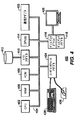
図2は、再循環された排気ガスの調整の非限定的な実施例である。多くの課題は、ガスタービン又は同様の機器のための吸気の代わりとしての再循環排気ガス(EGR)の使用に関連付けられる。EGRは、ガスタービンロータ及び他の関連する構成要素に損傷を与えない温度まで冷却すべきである。加えて、EGRは、できるだけ粒子状物質をなくすべきである。 FIG. 2 is a non-limiting example of adjustment of the recirculated exhaust gas. Many challenges are associated with the use of recirculated exhaust gas (EGR) as an alternative to intake air for gas turbines or similar equipment. The EGR should be cooled to a temperature that will not damage the gas turbine rotor and other related components. In addition, EGR should be free of particulate matter as much as possible.
この非限定的な実施例において、タービン排気ガス60は、排気ガスの温度を低下させるHRSG56を通過する。ダクトバーナー及びHRSG56内に位置する触媒床による反応は、排気ガス60においてすす及び粒子状物質形成の一因となる可能性がある。HRSG56は、排気ガス60がHRSG56の後端56Aの上部から出るように構成することができる。この構成は、56Bで示される領域において蒸気蓄積が抱える問題を和らげる。しかし、他の構成も本発明の技術的進歩とともに使用可能である。
In this non-limiting example,
HRSGから出ると、バイパススタックダンパー200は、バイパススタック202を介してタービン排気ガス60を大気に送ることができる。センサは、バイパススタックダンパー200に又はその近くにあってよい。このようなセンサは、温度、水濃度、及び/又は粒子状物質濃度を監視し、図1及び2に示すシステムを制御する1又は2以上のコンピュータに情報を通信することができる。温度、水濃度、及び/又は粒子状物質濃度が許容範囲外にある場合、コンピュータは、排気ガスを大気に送るようにダンパーを位置決めすることができる。温度、水濃度、及び/又は粒子状物質センサを検討するが、これらは単に例証に過ぎず、他の基準を監視するセンサを使用することができる。
Upon exiting the HRSG, the
排気ガス60を大気に送る理由がない場合、コンピュータは、排気ガス60を再循環配管に、次いですす洗浄/冷却セクション204に送るようにバイパススタックダンパー200を位置決めすることができる。
If there is no reason to send the
排気ガス60は、下向きにすす洗浄/冷却セクション204に流入することができる。すす洗浄/冷却セクション204は、下向きに冷たい浄水を噴霧するスプレーカラム204aを含む。パイプライン206は、濾過システム230(以下で検討する)からの冷たい浄水及び必要以上に何らかの補給用の冷たい浄水(発生源は図示せず)を担持する。冷たい浄水は、排気ガス60を冷却又は過熱防止し、粒子状物質の排気ガス60を洗浄する。スプレーカラム204aは、1又は2以上のジェット、ノズル、又はシャワーヘッドとすることができる。冷たい浄水を熱伝達媒体として使用して、本発明の実施形態において排気ガス60を冷却し、他の液体又は冷却剤は、場合によっては熱伝達媒体として使用することができる。過熱防止は、排気ガスがその露点を過ぎて冷却されていることを指す。
非限定的な実施形態において、並流(例えば、両方とも同じ方向及び下向きに流れる排気ガス及び排水)の直接接触式噴霧凝縮機は、設計のベースを形成し、排気ガスからの粒子状物質を冷却して除去する。すす洗浄/冷却セクション204を収容する容器は、任意選択的に、更に排気ガス60を冷却する追加の熱伝達媒体を含むことができる。このような追加の熱伝達媒体は、限定ではないが、梱包用トレイ及び表面凝縮機を含む。
In a non-limiting embodiment, a co-current (e.g., exhaust gas and waste water that both flow in the same direction and downward) forms the basis of the design and removes particulate matter from the exhaust gas. Cool to remove. The container containing the soot cleaning /
すす洗浄/冷却セクション204はまた、集水機208aを含む。集水機208aは、すす洗浄/冷却セクション204の底部にて暖かい汚れた水を集める。重力により、並流の結果として暖かい汚れた水が集水機208aに集まる。次いで、排水管、パイプ、バルブ、及び/又はポンプ210の収集により、暖かい汚れた水を水濾過システム230に送ることができる。
The soot cleaning /
すす洗浄/冷却セクション204に続いて、排気ガスは、離脱セクション212に流入する。離脱セクション212は、すす洗浄/冷却セクション204から持ち越されている可能性がある水/液滴を除去する。離脱セクション212は、水/液体及び残留液滴を同伴して集水機208bに送る単一ベーン又はベーンの組合せを含むことができる。一部の構成では、集水機208a及び208bは、互いに流体連通状態にすることができ、又は共通の集水機が、すす洗浄/冷却セクション204及び離脱セクション212の両方を使用可能にすることができる。同様に、集水機208bによって集められる水は、水濾過システムに送ることができる。
Following the soot cleaning /
離脱セクション212に続いて、排気ガスは、ブロア214を通過する。ブロア214は、排気ガスを再循環移送配管216に押し流すファンとすることができる。図2のシステムは、1つのブロアを示すが、システムは、必要に応じて再循環移送配管216に沿って位置決めされた複数のブロアを含むことができる。
Following the
再循環移送配管216を通って進むと、排気ガス60は、次に煙道ガス凝縮機218に流入する。煙道ガス凝縮機218は、加熱面を増加させて冷たい浄水パイプ220を通って循環する冷たい浄水に熱を伝達するバーを有するパイプで形成することができる。これに代えて、煙道ガス凝縮機は、凝縮コイルを含む除湿機とすることができる。煙道ガス凝縮機218は、適切な温度及び/又は湿度センサの使用によって、圧縮機SEGRガスタービンシステム52への入口に好適な所定の温度及び/又は湿度範囲まで排気ガスを更に冷却及び/又は除湿するようにコンピュータによって制御することができる。
As it travels through
煙道ガス凝縮機218に続いて、排気ガスは、集水機208aによって第2の離脱セクション222へ流れる。第2の離脱セクションは、FGCにおいて生成された凝縮物を除去する。任意選択的に、第2の離脱セクション222の前に、別のすす洗浄/冷却セクションを使用することができる。
Following the
第2の離脱セクション222に続いて、排気ガス60は、保護スタックダンパー224及び保護スタック226へ流れる。コンピュータは、1又は2以上のセンサを使用して、排気ガスの品質又はSEGRガスタービンシステム52の状態を監視し、ダンパーを制御して必要に応じて排気ガスを大気に送ることができる。第2の離脱セクション222の下流の保護スタック226は、排気ガスのいずれかの態様が望ましい水含有量、粒子状物質濃度、及び温度を提供できない場合、SEGRガスタービンシステム52の保護を可能にする。センサ及びコンピュータが、排気ガス60の水含有量、粒子状物質濃度、及び温度が許容限界内にあることを確認する場合、コンピュータは、排気ガス60をSEGRガスタービンシステム52の入口まで送るように保護スタックダンパー224を制御することができる。
Following the
上述の水濾過システム230は、図2のシステムにおいて用いられる水を浄化して再循環する手段を提供する。集水機208a及び208bによって集められた暖かい汚れた水は、フィルタ232を通過する。廃棄物234は廃棄される。暖かい浄水236は、プレート及びフレーム熱交換器238に送られる。集水機208cからの暖かい浄水はまた、パイプ240を介してプレート及びフレーム熱交換器238に送られる。プレート及びフレーム熱交換器は、すす洗浄/冷却セクション204に給送するパイプ206、及び煙道ガス凝縮機218を冷却するパイプ220に冷たい浄水を出力する。要素242及び246は、それぞれ冷却液タンク(図示せず)からの入口及び冷却液タンクへの出口である。
The
図3は、再循環された排気ガスの調整の工程の非限定的な実施例のフローチャートである。ステップ302は、排気ガスを熱回収蒸気発生機からタービン圧縮機入口まで送る調整ループを通して排気ガスを再循環するステップを含む。ステップ304は、コンピュータを用いて、排気ガスの大気放出を提供するバイパススタック又は排気ガス調整デバイスに排気ガスを送るようにダンパーアセンブリを制御するステップを含む。ステップ306は、排気ガス調整デバイスを用いて、排気ガスを冷却するステップを含む。ステップ308は、排気ガス調整デバイスを用いて、排気ガスから粒子状物質を除去するステップを含む。ステップ310は、離脱セクションを用いて、排気ガス調整デバイスによって導入された液体を排気ガスから除去するステップを含む。ステップ312は、煙道ガス凝縮機によって排気ガスを冷却及び除湿するステップを含む。ステップ314は、コンピュータを用いて、除湿機から後及びタービン圧縮機入口の前及び煙道ガス凝縮機から下流で排気ガスの大気放出を提供する保護スタック又はタービン圧縮機入口に排気ガスを送るようにダンパーアセンブリを制御するステップを含む。 FIG. 3 is a flowchart of a non-limiting example of a process for adjusting the recirculated exhaust gas. Step 302 includes recirculating the exhaust gas through a conditioning loop that routes the exhaust gas from the heat recovery steam generator to the turbine compressor inlet. Step 304 includes using a computer to control the damper assembly to route exhaust gas to a bypass stack or exhaust gas conditioning device that provides atmospheric emission of exhaust gas. Step 306 includes cooling the exhaust gas using an exhaust gas conditioning device. Step 308 includes removing particulate matter from the exhaust gas using an exhaust gas conditioning device. Step 310 includes using the separation section to remove liquid introduced by the exhaust gas conditioning device from the exhaust gas. Step 312 includes cooling and dehumidifying the exhaust gas with a flue gas condenser. Step 314 uses the computer to send exhaust gas to a protective stack or turbine compressor inlet that provides atmospheric emissions of exhaust gas after the dehumidifier and before the turbine compressor inlet and downstream from the flue gas condenser. The step of controlling the damper assembly.
図4は、図1及び2のシステムを制御するのに用いることができるコンピュータ400のブロック図である。中央演算処理ユニット(CPU)402は、システムバス404に連結される。CPU402は、あらゆる汎用CPUとすることができるが、他のタイプのCPU402のアーキテクチャ(又は例示のシステム400の他の構成要素)も、CPU402(及びシステム400の他の構成要素)が本明細書で説明するような作動をサポートする限り使用することができる。単一CPU402のみが図4に示されているが、追加のCPUが存在し得ることを当業者は認識するであろう。その上、コンピュータ400は、ハイブリッド並列CPU/GPUシステムを含むことができるネットワークで結んだマルチプロセッサコンピュータを含むことができる。CPU402は、本明細書で開示する種々の教示により種々の論理命令を実行することができる。例えば、CPU402は、説明した作動フローによる処理を実施するための機械レベルの命令を実行することができる。
FIG. 4 is a block diagram of a
コンピュータ400はまた、非一時的コンピュータ可読媒体などのコンピュータ構成要素を含むことができる。コンピュータ可読媒体の例は、SRAM、DRAM、SDRAM、又は同様のものとすることができるランダムアクセスメモリ(RAM)を含む。コンピュータ400はまた、PROM、EPROM、EEPROM、又は同様のものとすることができる読み取り専用メモリ(ROM)408などの追加の非一時的コンピュータ可読媒体を含むことができる。RAM406及びROM408は、当技術分野で公知のように、ユーザ及びシステムデータ及びプログラムを保持する。コンピュータ400はまた、入力/出力(I/O)アダプタ410、通信アダプタ422、ユーザインタフェースアダプタ424、及びディスプレイアダプタ418を含むことができる。
I/Oアダプタ410は、例えば、ハードドライブ、コンパクトディスク(CD)ドライブ、フロッピーディスクドライブ、テープドライブ、及び同様のものを含むストレージデバイス412などの追加の非一時的コンピュータ可読媒体をコンピュータ400に接続することができる。ストレージデバイスは、RAM406が、本技術の作動のためのデータの格納に関連付けられたメモリ要件にとって不十分であるときに使用することができる。コンピュータ400のデータストレージは、本明細書で開示するように使用又は生成する情報及び/又は他のデータを格納するために使用することができる。例えば、ストレージデバイス412を使用して、本技術に従って構成情報又は追加のプラグインを格納することができる。更に、ユーザインタフェースアダプタ424は、キーボード428、ポインティングデバイス426などのユーザ入力デバイス、及び/又は出力デバイスをコンピュータ400に連結する。ディスプレイアダプタ418は、CPU402によって駆動され、ディスプレイデバイス420上の表示を制御して例えば利用可能なプラグインに関してユーザに情報を提示する。
The I /
システム400のアーキテクチャは、必要に応じて変更することができる。例えば、以下に限定されるものではないが、パーソナルコンピュータ、ラップトップコンピュータ、コンピュータワークステーション、及びマルチプロセッササーバを含むあらゆる好適なプロセッサベースのデバイスを使用することができる。その上、本発明の技術的進歩は、アプリケーション固有の集積回路又は非常に大型の集積(VLSI)回路上に実装することができる。実際に、当業者は、本発明の技術的進歩により論理演算を実行することができるあらゆる数の好適なハードウェア構造を使用することができる。用語「処理回路」は、ハードウェアプロセッサ(上述のハードウェアデバイスに見られるものなど)、ASIC、及びVLSI回路を含む。コンピュータ400への入力データは、種々のプラグイン及びライブラリファイルを含むことができる。入力データは、それに追加して構成情報を含むことができる。
The architecture of the
図5は、再循環されたガスの調整を制御するための非限定的な方法を示している。図5のステップは、必ずしも列挙した順序で実施されるとは限らず、一部のステップは、他のものと同時に実施することができる。 FIG. 5 illustrates a non-limiting method for controlling the regulation of the recirculated gas. The steps of FIG. 5 are not necessarily performed in the order listed, and some steps can be performed concurrently with others.
ステップ502において、センサを使用して温度、粒子状物質濃度、湿度、及び/又は機器の作動ステータスを測定する。ステップ504において、コンピュータは、センサ読取値を事前に確立した基準と比較し、バイパススタック202を介して排気ガス60を大気に送り、又は排気ガス60をすす洗浄/冷却セクション204に送るようにバイパススタックダンパー200を制御する。ステップ506において、コンピュータ400は、冷たい浄水をスプレーカラム204aに供給できるようにするバルブを制御し、スプレーカラムは、次に、排気ガスを離脱セクション212を通して押し出すことができる。ステップ508において、コンピュータ400は、ブロア214をして再循環配管216を通して排気ガスを押し出させる。ステップ510において、コンピュータ400は、離脱セクション22を通過する前に排気ガス60を冷却及び/又は除湿するように煙道ガス凝縮機を制御する。ステップ512において、センサを使用して温度、粒子状物質濃度、湿度、及び/又は機器の作動ステータスを測定する。ステップ514において、コンピュータは、センサ読取値を事前に確立した基準と比較し、保護スタック226を介して排気ガス60を大気に送り、又は排気ガス60をSEGRガスタービンシステム52に送るように保護スタックダンパー224を制御する。ステップ516において、コンピュータ400は、図2に示すように水を再循環してそれを種々の構成要素に供給するように、システムの種々のパイプにおいて流水を制御するあらゆる関連するバルブと共に水濾過システムを制御する。
In
本書の説明は、最良モードを含む本発明を開示するために、かつ同じくあらゆる当業者がいずれかのデバイス又はシステムを作り、使用していずれかの組み込まれた方法を実行することを含む本発明を実施することを可能にするために実施例を使用している。本発明の特許請求可能な範囲は、特許請求の範囲によって定められ、かつ当業者に想起される他の実施例を含む場合がある。そのような他の実施例は、それらが、特許請求の範囲の文字通りの言語と異ならない構造要素を有する場合、又はそれらが、特許請求の範囲の文字通りの言語からの差異が実質的でない均等構造要素を含む場合には、特許請求の範囲内であるように意図している。 The description herein describes the present invention, including the best mode, and also includes any person skilled in the art making and using any device or system to perform any of the incorporated methods. The example is used to make it possible to implement. The patentable scope of the invention is defined by the claims, and may include other examples that occur to those skilled in the art. Such other embodiments are equivalent structures where they have structural elements that do not differ from the literal language of the claims, or where they differ substantially from the literal language of the claims. Where elements are included, they are intended to be within the scope of the claims.
12 炭化水素生成システム
14 タービンベースのサービスシステム
18 原油二次回収(EOR)システム
20 地下リザーバ
30 掘削ボア
12
Claims (13)
排気ガスを熱回収蒸気発生機からタービン圧縮機入口まで送る再循環排気ガス調整ループ、を備え、
前記再循環排気ガス調整ループは、
前記排気ガスを冷却して該排気ガスから粒子状物質を除去する排気ガス調整デバイスと、
前記排気ガスを除湿する除湿機と、を有している、
ことを特徴するシステム。 A system,
A recirculation exhaust gas adjustment loop that sends exhaust gas from the heat recovery steam generator to the turbine compressor inlet,
The recirculation exhaust gas adjustment loop includes:
An exhaust gas adjusting device that cools the exhaust gas to remove particulate matter from the exhaust gas;
A dehumidifier for dehumidifying the exhaust gas,
A system characterized by that.
請求項1に記載のシステム。 A separation section that is between the exhaust gas conditioning device and the dehumidifier and that removes liquid introduced by the exhaust gas conditioning device from the exhaust gas;
The system of claim 1.
請求項1または2に記載のシステム。 The exhaust gas conditioning device comprises a vertical direct contact condenser having a spray column that generates a co-flow of the exhaust gas and heat transfer liquid in the same downward direction.
The system according to claim 1 or 2.
請求項1ないし3のいずれか1項に記載のシステム。 The heat recovery steam generator further comprising a heat recovery steam generator, wherein the input to the recirculation gas regulation loop is in fluid communication with a top back section of the heat recovery steam generator;
The system according to any one of claims 1 to 3.
前記排気ガスの大気放出を提供するバイパススタックと、
前記排気ガスを前記バイパススタック又は前記排気ガス調整デバイスに送るダンパーアセンブリと、を更に備えている、
請求項1ないし4のいずれか1項に記載のシステム。 Before the exhaust gas regulating device,
A bypass stack that provides atmospheric emission of the exhaust gas;
A damper assembly for sending the exhaust gas to the bypass stack or the exhaust gas conditioning device.
The system according to any one of claims 1 to 4.
前記煙道ガス凝縮機は、前記排気ガスを冷却して除湿する、
請求項1ないし5のいずれか1項に記載のシステム。 The dehumidifier includes a flue gas condenser,
The flue gas condenser cools and dehumidifies the exhaust gas;
The system according to any one of claims 1 to 5.
前記排気ガスを前記保護スタック又は前記タービン圧縮機入口にかつ前記煙道ガス凝縮機から下流に送るダンパーアセンブリと、を更に備えている、
請求項1ないし6のいずれか1項に記載のシステム。 A protective stack that provides atmospheric release of the exhaust gas downstream from the dehumidifier and before the turbine compressor inlet;
A damper assembly for sending the exhaust gas to the protective stack or the turbine compressor inlet and downstream from the flue gas condenser;
The system according to any one of claims 1 to 6.
前記再循環させるステップが、
排気ガス調整デバイスを用いて、前記排気ガスを冷却するステップと、
前記排気ガス調整デバイスを用いて、前記排気ガスから粒子状物質を除去するステップと、
除湿機を用いて、前記排気ガスを除湿するステップと、を含む、
ことを特徴とする方法。 Recirculating the exhaust gas through a regulation loop that sends the exhaust gas from the heat recovery steam generator to the turbine compressor inlet;
The recycling step comprises:
Cooling the exhaust gas using an exhaust gas regulating device;
Removing particulate matter from the exhaust gas using the exhaust gas conditioning device;
Dehumidifying the exhaust gas using a dehumidifier,
A method characterized by that.
請求項8に記載の方法。 Further comprising removing liquid introduced by the exhaust gas conditioning device from the exhaust gas using a separation section between the exhaust gas conditioning device and the dehumidifier.
The method of claim 8.
前記方法が、
同じ下向き方向に前記スプレーカラムから放出される前記排気ガス及び熱伝達液体の並流を発生させるステップを含む、
請求項8又は9に記載の方法。 The exhaust gas conditioning device includes a vertical direct contact condenser having a spray column;
Said method comprises
Generating a co-flow of the exhaust gas and heat transfer liquid discharged from the spray column in the same downward direction,
10. A method according to claim 8 or 9.
請求項8ないし10のいずれか1項に記載の方法。 Using a computer to control the damper assembly to route the exhaust gas to or to a bypass stack that provides atmospheric release of the exhaust gas before the exhaust gas reaches the exhaust gas conditioning device Further including
11. A method according to any one of claims 8 to 10.
請求項8ないし11のいずれか1項に記載の方法。 The dehumidifying step comprises using a flue gas condenser;
12. A method according to any one of claims 8 to 11.
請求項13に記載の方法。 Using a computer to a protective stack that provides atmospheric release of the exhaust gas downstream from the dehumidifier and before the turbine compressor inlet and downstream from the flue gas condenser, or at the turbine compressor inlet Further comprising controlling the damper assembly to deliver the exhaust gas;
The method of claim 13.
Applications Claiming Priority (3)
| Application Number | Priority Date | Filing Date | Title |
|---|---|---|---|
| US201461970766P | 2014-03-26 | 2014-03-26 | |
| US61/970,766 | 2014-03-26 | ||
| PCT/US2015/012263 WO2015147974A1 (en) | 2014-03-26 | 2015-01-21 | System and method for the conditioning of recirculated exhaust gas |
Publications (1)
| Publication Number | Publication Date |
|---|---|
| JP2017519929A true JP2017519929A (en) | 2017-07-20 |
Family
ID=52574416
Family Applications (1)
| Application Number | Title | Priority Date | Filing Date |
|---|---|---|---|
| JP2016558750A Pending JP2017519929A (en) | 2014-03-26 | 2015-01-21 | System and method for adjustment of recirculated exhaust gas |
Country Status (5)
| Country | Link |
|---|---|
| US (1) | US20150275702A1 (en) |
| EP (1) | EP3123011A1 (en) |
| JP (1) | JP2017519929A (en) |
| CN (1) | CN106164443A (en) |
| WO (1) | WO2015147974A1 (en) |
Families Citing this family (2)
| Publication number | Priority date | Publication date | Assignee | Title |
|---|---|---|---|---|
| JP2020127100A (en) * | 2019-02-03 | 2020-08-20 | 株式会社bitFlyer Blockchain | Method for storing transaction representing asset transfer in distributed network having multiple nodes, program therefor, and node for configuring distributed network |
| CN112763445B (en) * | 2020-12-25 | 2022-08-16 | 上海琉兴环保科技有限公司 | Ultralow emission on-line monitoring system of coal fired power plant flue gas pollutant |
Citations (10)
| Publication number | Priority date | Publication date | Assignee | Title |
|---|---|---|---|---|
| JPS6186922A (en) * | 1984-10-04 | 1986-05-02 | Mitsubishi Heavy Ind Ltd | Wet exhaust gas treatment apparatus |
| JPH04267917A (en) * | 1991-02-25 | 1992-09-24 | Techno Ryowa:Kk | Blow-up air purification device |
| JPH11241804A (en) * | 1998-02-25 | 1999-09-07 | Toshiba Eng Co Ltd | Supporting structure |
| JPH11253733A (en) * | 1997-12-25 | 1999-09-21 | Chiyoda Corp | Method for two stage wet detoxification treatment of incinerator gas |
| JP2003028460A (en) * | 2001-07-18 | 2003-01-29 | Matsushita Seiko Co Ltd | Water tank |
| JP2008309153A (en) * | 2007-06-13 | 2008-12-25 | General Electric Co <Ge> | System and method for power generation with exhaust gas recirculation |
| JP2009108848A (en) * | 2007-10-30 | 2009-05-21 | General Electric Co <Ge> | System for recirculating exhaust gas of turbomachine |
| JP2009115086A (en) * | 2007-11-08 | 2009-05-28 | General Electric Co <Ge> | System for reducing sulfur oxide emission generated by turbomachine |
| WO2012148656A1 (en) * | 2011-04-25 | 2012-11-01 | Nooter/Eriksen, Inc. | Multidrum evaporator |
| WO2013163045A1 (en) * | 2012-04-26 | 2013-10-31 | General Electric Company | System and method of recirculating exhaust gas for use in a plurality of flow paths in a gas turbine engine |
Family Cites Families (15)
| Publication number | Priority date | Publication date | Assignee | Title |
|---|---|---|---|---|
| SE507409C2 (en) * | 1995-10-19 | 1998-05-25 | Vattenfall Ab | Procedure for fuel treatment |
| US5826518A (en) * | 1996-02-13 | 1998-10-27 | The Babcock & Wilcox Company | High velocity integrated flue gas treatment scrubbing system |
| DE10325111A1 (en) * | 2003-06-02 | 2005-01-05 | Alstom Technology Ltd | Method for generating energy in a gas turbine comprehensive power generation plant and power plant for performing the method |
| US7739874B2 (en) * | 2003-09-30 | 2010-06-22 | Bhp Billiton Innovation Pty. Ltd. | Power generation |
| US8051638B2 (en) * | 2008-02-19 | 2011-11-08 | General Electric Company | Systems and methods for exhaust gas recirculation (EGR) for turbine engines |
| US8448418B2 (en) * | 2008-03-11 | 2013-05-28 | General Electric Company | Method for controlling a flowrate of a recirculated exhaust gas |
| AU2011271634B2 (en) * | 2010-07-02 | 2016-01-28 | Exxonmobil Upstream Research Company | Stoichiometric combustion with exhaust gas recirculation and direct contact cooler |
| WO2012101087A1 (en) * | 2011-01-24 | 2012-08-02 | Alstom Technology Ltd | Mixing element for gas turbine units with flue gas recirculation |
| JP2014512471A (en) * | 2011-02-01 | 2014-05-22 | アルストム テクノロジー リミテッド | Combined cycle power plant with CO2 capture plant |
| JP5787838B2 (en) * | 2011-07-27 | 2015-09-30 | アルストム テクノロジー リミテッドALSTOM Technology Ltd | Gas turbine power plant with exhaust gas recirculation and method of operating the same |
| US8205455B2 (en) * | 2011-08-25 | 2012-06-26 | General Electric Company | Power plant and method of operation |
| EP2578839A1 (en) * | 2011-10-06 | 2013-04-10 | Alstom Technology Ltd | Method for the operation of a gas turbine with flue gas recirculation and corresponding apparatus |
| US9891001B2 (en) * | 2012-03-16 | 2018-02-13 | Evapco, Inc. | Hybrid cooler with bifurcated evaporative section |
| US9784185B2 (en) * | 2012-04-26 | 2017-10-10 | General Electric Company | System and method for cooling a gas turbine with an exhaust gas provided by the gas turbine |
| GB201218611D0 (en) * | 2012-10-17 | 2012-11-28 | Tuyere Ltd | Heat engine |
-
2015
- 2015-01-21 CN CN201580008155.2A patent/CN106164443A/en active Pending
- 2015-01-21 EP EP15706077.3A patent/EP3123011A1/en not_active Withdrawn
- 2015-01-21 JP JP2016558750A patent/JP2017519929A/en active Pending
- 2015-01-21 WO PCT/US2015/012263 patent/WO2015147974A1/en active Application Filing
- 2015-01-21 US US14/601,992 patent/US20150275702A1/en not_active Abandoned
Patent Citations (10)
| Publication number | Priority date | Publication date | Assignee | Title |
|---|---|---|---|---|
| JPS6186922A (en) * | 1984-10-04 | 1986-05-02 | Mitsubishi Heavy Ind Ltd | Wet exhaust gas treatment apparatus |
| JPH04267917A (en) * | 1991-02-25 | 1992-09-24 | Techno Ryowa:Kk | Blow-up air purification device |
| JPH11253733A (en) * | 1997-12-25 | 1999-09-21 | Chiyoda Corp | Method for two stage wet detoxification treatment of incinerator gas |
| JPH11241804A (en) * | 1998-02-25 | 1999-09-07 | Toshiba Eng Co Ltd | Supporting structure |
| JP2003028460A (en) * | 2001-07-18 | 2003-01-29 | Matsushita Seiko Co Ltd | Water tank |
| JP2008309153A (en) * | 2007-06-13 | 2008-12-25 | General Electric Co <Ge> | System and method for power generation with exhaust gas recirculation |
| JP2009108848A (en) * | 2007-10-30 | 2009-05-21 | General Electric Co <Ge> | System for recirculating exhaust gas of turbomachine |
| JP2009115086A (en) * | 2007-11-08 | 2009-05-28 | General Electric Co <Ge> | System for reducing sulfur oxide emission generated by turbomachine |
| WO2012148656A1 (en) * | 2011-04-25 | 2012-11-01 | Nooter/Eriksen, Inc. | Multidrum evaporator |
| WO2013163045A1 (en) * | 2012-04-26 | 2013-10-31 | General Electric Company | System and method of recirculating exhaust gas for use in a plurality of flow paths in a gas turbine engine |
Also Published As
| Publication number | Publication date |
|---|---|
| CN106164443A (en) | 2016-11-23 |
| US20150275702A1 (en) | 2015-10-01 |
| EP3123011A1 (en) | 2017-02-01 |
| WO2015147974A1 (en) | 2015-10-01 |
Similar Documents
| Publication | Publication Date | Title |
|---|---|---|
| JP7029378B2 (en) | Systems and methods for oxidant compression in quantitative exhaust gas recirculation gas turbine systems | |
| JP6336591B2 (en) | System and method for an oxidant heating system | |
| JP6452684B2 (en) | System and method for monitoring a gas turbine system having exhaust gas recirculation | |
| JP6289447B2 (en) | System and method for recirculating exhaust gas for use in multiple flow paths of a gas turbine engine | |
| AU2013337667B2 (en) | System and method for diffusion combustion in a stoichiometric exhaust gas recirculation gas turbine system | |
| US20150033751A1 (en) | System and method for a water injection system | |
| JP6532468B2 (en) | System and method for a gas turbine engine | |
| JP2017524095A (en) | Corrosion suppression system and method in an exhaust gas recirculation gas turbine system | |
| JP6641307B2 (en) | Combustion control method and system for gas turbine system with exhaust gas recirculation | |
| US20140182299A1 (en) | System and method for reheat in gas turbine with exhaust gas recirculation | |
| JP2009108848A (en) | System for recirculating exhaust gas of turbomachine | |
| JP2015518540A (en) | System and method for stoichiometric EGR gas turbine system | |
| JP2016523344A (en) | System and method for controlling exhaust gas flow in an exhaust gas recirculation gas turbine system | |
| JP2008309153A (en) | System and method for power generation with exhaust gas recirculation | |
| CN102985665A (en) | Low emission triple-cycle power generation systems and methods | |
| JP2018507974A (en) | System and method for estimating combustion equivalence ratio in a gas turbine with exhaust recirculation | |
| JP2017519929A (en) | System and method for adjustment of recirculated exhaust gas | |
| JP2011127597A (en) | System and method for reducing sulfur compounds within fuel stream for turbomachine | |
| TWI602985B (en) | System and method for diffusion combustion in a stoichiometric exhaust gas recirculation gas turbine system | |
| TWI644016B (en) | System and method for diffusion combustion with oxidant-diluent mixing in a stoichiometric exhaust gas recirculation gas turbine system | |
| TWI602986B (en) | System and method for load control with diffusion combustion in a stoichiometric exhaust gas recirculation gas turbine system |
Legal Events
| Date | Code | Title | Description |
|---|---|---|---|
| RD04 | Notification of resignation of power of attorney |
Free format text: JAPANESE INTERMEDIATE CODE: A7424 Effective date: 20170425 |
|
| A131 | Notification of reasons for refusal |
Free format text: JAPANESE INTERMEDIATE CODE: A131 Effective date: 20170724 |
|
| A02 | Decision of refusal |
Free format text: JAPANESE INTERMEDIATE CODE: A02 Effective date: 20180305 |