JP2017518892A - Electric tool and modular braking device for electric tool - Google Patents
Electric tool and modular braking device for electric tool Download PDFInfo
- Publication number
- JP2017518892A JP2017518892A JP2016572807A JP2016572807A JP2017518892A JP 2017518892 A JP2017518892 A JP 2017518892A JP 2016572807 A JP2016572807 A JP 2016572807A JP 2016572807 A JP2016572807 A JP 2016572807A JP 2017518892 A JP2017518892 A JP 2017518892A
- Authority
- JP
- Japan
- Prior art keywords
- driven shaft
- braking
- power tool
- drive
- braking element
- Prior art date
- Legal status (The legal status is an assumption and is not a legal conclusion. Google has not performed a legal analysis and makes no representation as to the accuracy of the status listed.)
- Granted
Links
Images


Classifications
-
- B—PERFORMING OPERATIONS; TRANSPORTING
- B23—MACHINE TOOLS; METAL-WORKING NOT OTHERWISE PROVIDED FOR
- B23Q—DETAILS, COMPONENTS, OR ACCESSORIES FOR MACHINE TOOLS, e.g. ARRANGEMENTS FOR COPYING OR CONTROLLING; MACHINE TOOLS IN GENERAL CHARACTERISED BY THE CONSTRUCTION OF PARTICULAR DETAILS OR COMPONENTS; COMBINATIONS OR ASSOCIATIONS OF METAL-WORKING MACHINES, NOT DIRECTED TO A PARTICULAR RESULT
- B23Q11/00—Accessories fitted to machine tools for keeping tools or parts of the machine in good working condition or for cooling work; Safety devices specially combined with or arranged in, or specially adapted for use in connection with, machine tools
- B23Q11/0078—Safety devices protecting the operator, e.g. against accident or noise
- B23Q11/0092—Safety devices protecting the operator, e.g. against accident or noise actuating braking or stopping means
-
- B—PERFORMING OPERATIONS; TRANSPORTING
- B25—HAND TOOLS; PORTABLE POWER-DRIVEN TOOLS; MANIPULATORS
- B25F—COMBINATION OR MULTI-PURPOSE TOOLS NOT OTHERWISE PROVIDED FOR; DETAILS OR COMPONENTS OF PORTABLE POWER-DRIVEN TOOLS NOT PARTICULARLY RELATED TO THE OPERATIONS PERFORMED AND NOT OTHERWISE PROVIDED FOR
- B25F5/00—Details or components of portable power-driven tools not particularly related to the operations performed and not otherwise provided for
- B25F5/001—Gearings, speed selectors, clutches or the like specially adapted for rotary tools
-
- B—PERFORMING OPERATIONS; TRANSPORTING
- B24—GRINDING; POLISHING
- B24B—MACHINES, DEVICES, OR PROCESSES FOR GRINDING OR POLISHING; DRESSING OR CONDITIONING OF ABRADING SURFACES; FEEDING OF GRINDING, POLISHING, OR LAPPING AGENTS
- B24B23/00—Portable grinding machines, e.g. hand-guided; Accessories therefor
- B24B23/02—Portable grinding machines, e.g. hand-guided; Accessories therefor with rotating grinding tools; Accessories therefor
- B24B23/022—Spindle-locking devices, e.g. for mounting or removing the tool
-
- B—PERFORMING OPERATIONS; TRANSPORTING
- B24—GRINDING; POLISHING
- B24B—MACHINES, DEVICES, OR PROCESSES FOR GRINDING OR POLISHING; DRESSING OR CONDITIONING OF ABRADING SURFACES; FEEDING OF GRINDING, POLISHING, OR LAPPING AGENTS
- B24B23/00—Portable grinding machines, e.g. hand-guided; Accessories therefor
- B24B23/02—Portable grinding machines, e.g. hand-guided; Accessories therefor with rotating grinding tools; Accessories therefor
- B24B23/028—Angle tools
-
- B—PERFORMING OPERATIONS; TRANSPORTING
- B24—GRINDING; POLISHING
- B24B—MACHINES, DEVICES, OR PROCESSES FOR GRINDING OR POLISHING; DRESSING OR CONDITIONING OF ABRADING SURFACES; FEEDING OF GRINDING, POLISHING, OR LAPPING AGENTS
- B24B47/00—Drives or gearings; Equipment therefor
- B24B47/26—Accessories, e.g. stops
-
- H—ELECTRICITY
- H02—GENERATION; CONVERSION OR DISTRIBUTION OF ELECTRIC POWER
- H02K—DYNAMO-ELECTRIC MACHINES
- H02K7/00—Arrangements for handling mechanical energy structurally associated with dynamo-electric machines, e.g. structural association with mechanical driving motors or auxiliary dynamo-electric machines
- H02K7/10—Structural association with clutches, brakes, gears, pulleys or mechanical starters
- H02K7/104—Structural association with clutches, brakes, gears, pulleys or mechanical starters with eddy-current brakes
-
- H—ELECTRICITY
- H02—GENERATION; CONVERSION OR DISTRIBUTION OF ELECTRIC POWER
- H02K—DYNAMO-ELECTRIC MACHINES
- H02K7/00—Arrangements for handling mechanical energy structurally associated with dynamo-electric machines, e.g. structural association with mechanical driving motors or auxiliary dynamo-electric machines
- H02K7/14—Structural association with mechanical loads, e.g. with hand-held machine tools or fans
- H02K7/145—Hand-held machine tool
Abstract
【課題】【解決手段】付設の駆動モータによって駆動可能な従動軸(210)と、付設の駆動モータの非通電状態で回転している従動軸(210)を制動するための制動装置(140)とを備えた電動工具であって、従動軸(210)が付設のハウジング内に回転運動可能に支持され、制動装置(140)が、少なくとも1つの第1および第2の制動要素(260,250)を備えた磁場ブレーキユニット(270)を有している電動工具において、第1の制動要素(260)は、従動軸(210)に対し半径方向に位置するように付設のハウジング内に相対回転不能に配置され、且つ従動軸(210)の周方向に交代する磁場を生成させるために少なくとも1つの第1および第2の磁極を備え、第2の制動要素(250)は、磁気誘導可能であり、且つ起動可能な連結装置(290)を介して従動軸(210)と回転運動可能に結合されている。【選択図】図2A driven shaft (210) that can be driven by an attached drive motor, and a braking device (140) for braking the driven shaft (210) rotating in a non-energized state of the attached drive motor. A driven shaft (210) is rotatably supported in an attached housing, and a braking device (140) is provided with at least one first and second braking elements (260, 250). In the electric tool having the magnetic field brake unit (270) with the first brake element (260), the first brake element (260) rotates relative to the driven shaft (210) in a radial direction relative to the driven shaft (210). The at least one first and second magnetic poles are provided for generating a magnetic field which is arranged in an impediment and alternates in the circumferential direction of the driven shaft (210), the second braking element (250) being magnetically inducible There are pivotable coupled a driven shaft (210) and through a bootable coupling device (290). [Selection] Figure 2
Description
本発明は、付設の駆動モータによって駆動可能な従動軸と、前記付設の駆動モータの非通電状態で回転している前記従動軸を制動するための制動装置とを備え、前記従動軸が付設のハウジング内に回転運動可能に支持され、前記制動装置が、少なくとも1つの第1および第2の制動要素を備えた磁場ブレーキユニットを有している電動工具に関するものである。 The present invention comprises a driven shaft that can be driven by an attached drive motor, and a braking device for braking the driven shaft that is rotating in a non-energized state of the attached drive motor, the driven shaft being attached. The invention relates to a power tool that is rotatably supported in a housing and in which the braking device has a magnetic brake unit with at least one first and second braking element.
特許文献1から、ドライブトレインと磁場ブレーキユニットとを備えたこの種の電動工具が知られている。この磁場ブレーキユニットは、電動工具に付設のハウジング内に回転可能に配置され、マグネットリングのように形成されている2つの第1の制動要素と、両第1の制動要素の間に配置され、銅円板のように形成されている相対回転不能な第2の制動要素とを有している。 From Patent Document 1, this type of electric tool including a drive train and a magnetic field brake unit is known. The magnetic field brake unit is rotatably disposed in a housing attached to the electric power tool, and is disposed between two first braking elements formed like a magnet ring and both first braking elements, And a second braking element which is formed like a copper disk and is relatively non-rotatable.
この技術水準の欠点は、磁場ブレーキユニットの両第1の制動要素がその回転可能な配置によって比較的強い機械的負荷を受け、それによってその寿命が減少し、したがって総じて電動工具の製品寿命が減少することがある。 The disadvantage of this state of the art is that both first braking elements of the magnetic brake unit are subjected to a relatively strong mechanical load due to their rotatable arrangement, thereby reducing their life and thus overall reducing the product life of the power tool. There are things to do.
それ故、本発明の課題は、安全且つ堅牢であり、適当な寿命の延長を達成でき、その結果総じて電動工具の対応する製品寿命の延長が可能になる、ブレーキ装置を備えた新たな電動工具を提供することである。 Therefore, the object of the present invention is to provide a new electric tool with a brake device which is safe and robust and can achieve a suitable extension of the service life, so that the corresponding product life of the power tool can be extended as a whole. Is to provide.
この課題は、付設の駆動モータによって駆動可能な従動軸と、前記付設の駆動モータの非通電状態で回転している前記従動軸を制動するための制動装置とを備え、前記従動軸が付設のハウジング内に回転運動可能に支持され、前記制動装置が、少なくとも1つの第1および第2の制動要素を備えた磁場ブレーキユニットを有している電動工具によって解決される。前記第1の制動要素は、前記従動軸に対し半径方向に位置するように前記付設のハウジング内に相対回転不能に配置され、且つ前記従動軸の周方向に交代する磁場を生成させるために少なくとも1つの第1および第2の磁極を備えている。前記第2の制動要素は、磁気誘導可能であり、且つ起動可能な連結装置を介して前記従動軸と回転運動可能に結合されている。 The subject includes a driven shaft that can be driven by an attached drive motor, and a braking device that brakes the driven shaft that rotates in a non-energized state of the attached drive motor. Solved by a power tool having a magnetic field brake unit with at least one first and second braking element, the brake device being supported for rotational movement in a housing. The first braking element is disposed in the attached housing so as to be relatively non-rotatable so as to be positioned in a radial direction with respect to the driven shaft, and at least for generating a magnetic field alternating in the circumferential direction of the driven shaft. One first and second magnetic poles are provided. The second braking element is magnetically inductible and is coupled to the driven shaft in a rotational motion via a startable coupling device.
したがって本発明により、安全且つ堅牢であり、第1の制動要素をハウジング内に相対回転不能に配置することで該第1の制動要素に対する機械的負荷が少なく、したがってブレーキ装置の寿命を延長でき、総じて電動工具の寿命を延長できる、ブレーキ装置を備えた電動工具の提供が可能になる。 Therefore, according to the present invention, it is safe and robust, and the first braking element is disposed in the housing in a relatively non-rotatable manner so that there is less mechanical load on the first braking element, thus extending the life of the braking device, It is possible to provide a power tool equipped with a brake device that can extend the life of the power tool as a whole.
一実施形態によれば、起動可能な連結装置は、起動時に第2の制動要素を、付設の駆動モータの非通電状態で、回転している従動軸と相対回転不能に結合させるように形成されている。 According to one embodiment, the activatable coupling device is configured to couple the second braking element in a non-rotatable manner with the driven shaft that is rotating in a non-energized state of the attached drive motor at the time of activation. ing.
これにより、摩耗に乏しく、安定なブレーキ装置を提供することができる。 As a result, it is possible to provide a stable brake device with little wear.
好適には、起動可能な連結装置は、付設の駆動モータの通電状態で、第2の制動要素に対する従動軸の回転を可能にするように形成されている。 Preferably, the startable coupling device is configured to allow rotation of the driven shaft relative to the second braking element when the attached drive motor is energized.
これにより、電動工具の標準作動時でのブレーキ装置の非作動状態を簡単に且つ高い信頼性で達成できる。 Thereby, the non-operation state of the brake device at the time of the standard operation of the electric tool can be achieved easily and with high reliability.
磁場ブレーキユニットは、好ましくは渦電流ブレーキのように形成されている。 The magnetic brake unit is preferably formed like an eddy current brake.
これにより、安全かつ安定な磁場ブレーキユニットを提供することができる。 Thereby, a safe and stable magnetic field brake unit can be provided.
一実施形態によれば、第1および第2の制動要素はそれぞれ少なくとも部分的にリングセグメント状に形成され、第1の制動要素は第2の制動要素の端面の領域に配置されている。 According to one embodiment, the first and second braking elements are each formed at least partly in the form of a ring segment, the first braking element being arranged in the region of the end face of the second braking element.
これにより、本発明は、電動工具のハウジング内での第1および第2の制動要素の簡潔で省スペースな配置を可能にする。 Thus, the present invention allows a simple and space-saving arrangement of the first and second braking elements within the housing of the power tool.
第1の制動要素は、好ましくは、従動軸を周囲から取り囲んでいる永久磁石リングのように形成されている。 The first braking element is preferably formed like a permanent magnet ring surrounding the driven shaft from the periphery.
これにより、堅牢で安定な第1の制動要素を提供できる。 Thereby, a robust and stable first braking element can be provided.
第2の制動要素は、好適には、従動軸を周囲から取り囲んでいるリングのように、特に鉄リングまたは銅リングのように形成されている。 The second braking element is preferably formed like a ring surrounding the driven shaft from the periphery, in particular like an iron ring or a copper ring.
これにより、簡潔でコスト上好ましい第2の制動要素を提供できる。 As a result, the second braking element that is simple and cost-effective can be provided.
好ましくは、第2の制動要素は、起動可能な連結装置に付設されている駆動部材と相対回転不能に結合され、該駆動部材は、複数のブロッキング部材を介して、特にころ状のブロッキング部材を介して、付設の駆動モータの非通電状態で、回転している従動軸と相対回転不能に結合可能である。 Preferably, the second braking element is non-rotatably coupled to a drive member attached to the activatable coupling device, the drive member having a roller-shaped blocking member in particular via a plurality of blocking members. Thus, in a non-energized state of the attached drive motor, it can be coupled to the rotating driven shaft in a relatively non-rotatable manner.
これにより、第2の制動要素を、駆動モータの非通電状態でハウジング内に相対回転不能に簡単に配置することができる。 As a result, the second braking element can be easily arranged in the housing so as not to rotate relative to the drive motor in a non-energized state.
従動軸上にして、好適には複数のブロッキング部材の領域に、従動軸と相対回転不能に結合され、起動可能な連結装置に付設されている駆動体が配置されている。 On the driven shaft, a drive body attached to a startable coupling device is disposed, preferably coupled to the driven shaft so as not to rotate relative to the area of the plurality of blocking members.
これにより、連結装置の起動時に第2の制動要素を従動軸と連結させる駆動体を提供することができる。 Thereby, the drive body which connects a 2nd braking element with a driven shaft at the time of starting of a connection apparatus can be provided.
駆動体は、好適には、少なくとも略多角形状の外周を有している。 The driver preferably has at least a substantially polygonal outer periphery.
これにより、多角形状の外周がブロッキング部材との協働のための複数の傾斜部を形成するような、簡潔で信頼性のある駆動体を提供できる。 Thereby, a simple and reliable driving body can be provided in which the outer periphery of the polygonal shape forms a plurality of inclined portions for cooperation with the blocking member.
好ましくは、駆動体は、起動可能な連結装置に付設されているアクチュエータを介して、駆動部材と連結され、アクチュエータ内に、複数のブロッキング部材が少なくとも部分的に受容されている。 Preferably, the driving body is coupled to the driving member via an actuator attached to the actuating coupling device, and a plurality of blocking members are at least partially received in the actuator.
これにより、駆動体を迅速かつ簡単に駆動部材と連結させることができる。 Thereby, a drive body can be connected with a drive member quickly and easily.
アクチュエータは、一実施形態によれば、従動軸を回転運動可能に駆動するために駆動要素と相対回転不能に結合され、駆動要素は、所定の角度範囲内での従動軸の駆動要素に対する相対的な回転を可能にするために、従動軸で遊びをもって支持されている。 The actuator, according to one embodiment, is non-rotatably coupled to the drive element to drive the driven shaft for rotational movement, the drive element being relative to the drive element of the driven shaft within a predetermined angular range. In order to enable a smooth rotation, it is supported with play on the driven shaft.
これにより、駆動要素に対する従動軸の相対回転を簡単に可能にすることができる。 Thereby, the relative rotation of the driven shaft with respect to the drive element can be easily enabled.
好適には、付設の駆動モータの非通電状態で従動軸が回転しているとき、駆動体は、回転している従動軸に対するアクチュエータのトルク逆転と、これから生じる駆動体とアクチュエータとの間の相対回転とにより、複数のブロッキング部材を介して駆動部材と相対回転不能に結合可能である。 Preferably, when the driven shaft is rotated while the attached drive motor is de-energized, the drive body is configured such that the torque reverse of the actuator with respect to the rotating driven shaft and the relative relationship between the drive body and the actuator resulting therefrom By rotation, it can be coupled to the drive member through a plurality of blocking members so as not to be relatively rotatable.
これにより、制動装置を自動的に、すなわち利用者による外部操作なしに、対応する相対回転によって起動させることができる。 Thus, the braking device can be automatically activated, that is, without corresponding external operation by the user, by the corresponding relative rotation.
一実施形態によれば、電動工具はアングルグラインダのように形成されている。 According to one embodiment, the power tool is formed like an angle grinder.
これにより、本発明による制動装置をアングルグラインダにも簡単に使用することができる。 As a result, the braking device according to the present invention can be easily used for an angle grinder.
冒頭で述べた課題は、さらに、付設の駆動モータによって駆動可能で且つ付設のハウジング内に回転運動可能に支持されている従動軸を有している電動工具のためのモジュール状制動装置であって、少なくとも1つの第1および第2の制動要素を備えている磁場ブレーキユニットを備えた前記モジュール状制動装置によっても解決される。前記第1の制動要素は、前記従動軸に対し半径方向に位置するように前記付設のハウジング内に相対回転不能に固定可能であり、且つ前記従動軸の周方向に交代する磁場を生成させるために少なくとも1つの第1および第2の磁極を備え、前記第2の制動要素は、磁気誘導可能であり、且つ起動可能な連結装置を介して前記従動軸と回転運動可能に結合可能である。 The problem mentioned at the outset is further a modular braking device for an electric tool which has a driven shaft which can be driven by an attached drive motor and which is supported in a rotatable manner in an attached housing. It is also solved by said modular braking device comprising a magnetic brake unit comprising at least one first and second braking element. The first braking element can be fixed in the attached housing so as not to rotate relative to the driven shaft so as to be positioned in a radial direction, and generates a magnetic field that alternates in the circumferential direction of the driven shaft. At least one first and second magnetic pole, wherein the second braking element is magnetically inducible and can be rotatably coupled to the driven shaft via an actuable coupling device.
本発明を、図面に図示した実施例を用いて以下の説明で詳細に説明する。 The invention will be described in detail in the following description with reference to the embodiments illustrated in the drawings.
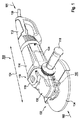
図1は、アングルグラインダとして形成された、一実施形態による制動装置140を備える電動工具100を示している。なお、電動工具100はアングルグラインダとして例示して説明するにすぎず、本発明を限定するためのものではないことを指摘しておく。本発明は、むしろ一般に、駆動モータと本発明による制動装置とを具備した電動工具、または、具備可能な電動工具、特に携帯型電動工具で使用することができる。本発明のコンテクストでは、「携帯型電動工具」とは、利用者が搬送機を用いずに搬送することのできる電動工具である。さらに、制動装置は任意の電動工具内部にたとえば差し込み型コネクタを介してモジュール状に組み込むことができる。また電動工具100は好ましくは50kg未満の質量を持ち、好適には20kg未満、特に好適には10kg未満の質量を持つ。
FIG. 1 shows a
アングルグラインダ100に付設の工具ハウジング110内には、好適には、従動ユニット130を駆動するための駆動モータ120が設けられている。好適には、駆動モータ120は電子整流式電動機として形成されているが、任意の他の電動機であってよい。好ましくは、従動ユニット130は従動軸(図2の210)を有し、従動軸はたとえば砥石車として形成されている差し込み工具134を駆動するために用いられる。差し込み工具134には、たとえば研磨粒から保護するために好適には保護フード132が付設されている。
A
図示の例では、駆動モータ120は工具ハウジング110の付設のモータ部分114内に配置され、従動ユニット130は伝動装置部分116内に配置されている。伝動装置部分116はアングルグラインダ100または工具ハウジング110の第1の軸線方向端部102に配置され、図示の例では補助グリップ118を備えている。補助グリップは、好適にはアングルグラインダ100の主延在方向104に対し横方向に延在している。アングルグラインダ100または工具ハウジング110の第1の軸線方向端部に対し軸線方向に対向している第2の軸線方向端部101の領域には、好適には、少なくとも部分的に(主)ハンドグリップ112が形成されている。さらに、第2の軸線方向端部101には、たとえば少なくとも駆動モータ120に電源に依存して給電するための電流ケーブル150が配置されている。しかし、第2の軸線方向端部101に、少なくとも駆動モータ120に電源とは独立に給電するためのバッテリーパックを配置してもよい。
In the illustrated example, the
一実施形態によれば、アングルグラインダ100に付設の制動装置140は、駆動モータ120の非通電状態で回転する従動ユニット130の従動軸(図2の210)を制動させるために形成されている。この場合制動装置140は好適には、自動的に起動、停止するように形成されている。その際に制動装置140は、駆動モータ120が通電されていないときに作動し、駆動モータ120が通電されると停止する。好ましくは、制動装置140はアングルグラインダ100のランアウトタイムを減少させ、すなわち駆動モータ120をオフにしてから差し込み工具134が停止するまでの時間を、好適には最大で2秒ないし3秒へ減少させる。
According to one embodiment, the
図2は、従動軸210を備えた図1の従動ユニット130を示している。従動軸は、第1の軸線方向端部201に、工具ハウジング110内での支持のための第1の部分211を有し、該第1の部分は、図示の例では段階的に第2の部分213と第3の部分215へ拡大し、第3の部分215を起点として、第1の軸線方向端部201に対向している第2の軸線方向端部202の領域において、図示の例では再び第4の部分217へ縮小している。好ましくは、第4の部分217は差し込み工具134を受容するために形成されている。
FIG. 2 shows the driven
従動軸210は、好適には、少なくとも1つの軸受要素214を介して、たとえば軸受フランジとして形成されているハウジング閉鎖要素216内で回転運動可能に支持されている。その際、好ましくは、軸受要素214は従動軸210の第2の部分213上に配置されて、その第3の部分215によってその第2の軸線方向端部202の方向に位置固定されている。
The driven
従動軸210の第1の軸線方向端部201の領域には、または、該従動軸の第2の部分213には、好適には、伝動装置入力歯車として形成され、図示の例ではリングギヤのように成形された駆動要素220が、好適には遊びをもって、しかし相対回転不能に配置されている。駆動要素220は、従動軸210の第1の軸線方向端部201側の第1の端面221に、たとえば歯部224を有している。この歯部224を介して、好ましくは駆動モータ120の回転運動を従動軸210へ、よって差し込み工具134へ伝達させることができる。第1の端面221に対向している、駆動要素220の第2の端面223には、好適には、少なくとも1つの回転駆動要素222が配置され、該回転駆動要素は、好ましくは、駆動要素220と相対回転不能に結合され、および/または、これに一体成形またはこれと一体形成され、制動装置140と作用結合している。
The region of the first
一実施形態によれば、制動装置140は磁場ブレーキユニット270を有し、磁場ブレーキユニットは、好ましくは渦電流ブレーキのように形成され、少なくとも1つの第1および第2の制動要素260,250を有している。第1の制動要素260は、好ましくは従動軸210に対し半径方向に配置され、好適には工具ハウジング110内または軸受フランジ216に相対回転不能に配置されている。
According to one embodiment, the
図示の例では、第1の制動要素260は、軸受フランジ216に付設されている、または、該軸受フランジに設けられている受容部299内に配置され、該受容部は好ましくは2つの部分から形成されている。この場合、好ましくは、第1の受容要素276が第1の制動要素260を軸線方向において支持し、第2の受容要素274は第1の制動要素260を半径方向外側において支持している。第1の制動要素260は、従動軸210の周方向において交替する磁場(図4の420)を発生させるために、好適には少なくとも1つの第1および第2の磁極(図3の362,364)を備えている。好ましくは、第1の制動要素260は少なくとも部分的にリングセグメント状に形成されて、好適には従動軸210を周囲から取り囲む永久磁石リングのように形成されている。なお、第1の制動要素260をマグネットリングとして構成することは単に一例の特徴にすぎず、第1の制動要素260は複数のリングセグメントから形成されていてもよいことを指摘しておく。この場合、複数のリングセグメントの各リングセグメントは磁極(図3の362,364)を形成することができる。さらに、第1の制動要素260は好適には第2の制動要素250の端面252の領域に配置され、図の例では第2の制動要素250の、従動軸210の第2の軸線方向端部202側の端面252上に配置されている。
In the example shown, the
一実施形態によれば、第2の制動要素250は磁気誘導可能であり、好ましくは少なくとも部分的にリングセグメント状である。好適には、第2の制動要素250は、従動軸210を周囲から取り囲むリングのように形成され、特に鉄リングまたは銅リングとして形成されている。
According to one embodiment, the
好適には、第2の制動要素250は起動可能な連結装置290を介して従動軸210と回転運動可能に結合されている。この連結装置290は、好ましくは、起動時に第2の制動要素250を、付設の駆動モータ120の非通電状態で、すなわち図1の電動工具100の制動時に、回転している従動軸210と相対回転不能に結合させ、好ましくは図1の駆動モータ120の通電状態で、すなわち図1の電動工具100の緊急作動時または自由回転時に、第2の制動要素250に対する従動軸210の回転を可能にするように形成されている。
Preferably, the
一実施形態によれば、連結装置290には駆動部材272が付設され、該駆動部材は、複数のブロッキング部材240を介して、特にころ状のブロッキング部材240を介して、図1の駆動モータ120の非通電状態で、回転している従動軸210と相対回転不能に結合可能である。好ましくは、駆動部材272は第2の制動要素250と相対回転不能に結合されている。
According to one embodiment, the
さらに、連結装置290には、好適には駆動体280が付設されている。駆動体は、従動軸210上に、好ましくは複数のブロッキング部材240の領域に配置され、従動軸210と相対回転不能に結合されている。図示の例では、駆動体280は、少なくとも略多角形状の外周を有し、好ましくは、連結装置290に付設されているアクチュエータ230を介して駆動部材272と連結されている。一実施形態では、駆動部材272と受容部299の第1および第2の受容要素276,274とは、磁場ブレーキユニット270のヨーク要素として形成されている。
Further, the connecting
好適には、アクチュエータ230内には、複数のブロッキング部材240が少なくとも部分的に受容されている。さらに、アクチュエータ230は、好ましくは、従動軸210を回転運動可能に駆動するために駆動要素220と相対回転不能に結合されている。この場合駆動要素220は、該駆動要素220に対する従動軸210の相対回転を、好ましくは少なくとも5゜ないし15゜の所定角度範囲内で可能にするために、上述したように遊びをもって従動軸210と結合されている。
Preferably, a plurality of blocking
一実施形態によれば、図1の電動工具100の制動時に、図1の駆動モータ120の非通電状態で従動軸210が回転しているとき、駆動体280はアクチュエータ230のトルク逆転によって、回転している従動軸210に対し相対的に回転する。これから生じる駆動体280とアクチュエータ230との間の相対回転により、駆動体280は複数のブロッキング部材240を介して駆動部材272と相対回転不能に結合される。
According to the embodiment, when the driven
図3は、渦電流ブレーキとして形成され、以下ではこのようにも記す図2の磁場ブレーキユニット270の構成の一例を示している。この場合、渦電流ブレーキ270の連結装置290はスピンドルロックのように構成されている。これに対応して、駆動体280は多角形状の外周を有している。この外周は、複数のブロッキング部材240の少なくとも1つのブロッキング部材、図示の例では6つの付設のブロッキング部材351,352,353,354,355,356を配置するために、たとえば6つの平坦部321,322,323,324,325,326を備えている。2つの平坦部321ないし326の間には、それぞれ駆動体280の平坦化したエッジ331,332,333,334,335,336が形成されている。
FIG. 3 shows an example of the configuration of the magnetic
図の例では、各ブロッキング部材351ないし356はそれぞれ、アクチュエータ230の周方向において互いに隣り合っているカラー状の2つの位置調整アームの間で取り囲まれている。以下では、それぞれ2つの位置調整アームの間にブロッキング部材351ないし356を配置する構成をブロッキング部材351を例に挙げて説明する。このブロッキング部材は、図の例では、第1の位置調整アーム342と第2の位置調整アーム344との間に配置され、第1および第2の位置調整アームは、それぞれ第1の周囲端部311および第2の周囲端部313を有している。図の例では、ブロッキング部材351は第1の位置調整アーム342の第2の周囲端部313の領域に配置されている。
In the illustrated example, each of the blocking
図3は、さらに、好ましくは永久磁石リングとして形成され、少なくとも1つの第1および第2の磁極362,364を備えた第1の制動要素260を示している。図の例では、複数の第1および第2の磁極362,364が連結装置290の周方向にそれぞれ交互に配置されている。これにより、磁極362,364は、連結装置290の周方向に交代する磁場(図4の420)を形成させる。
FIG. 3 further shows a
図4は、図2の制動装置140の磁場420を例示したものである。この磁場420は、図1の電動工具100の制動時に磁場ブレーキユニット270によって発生する複数の磁力線411,412,413,414,415,416によって形成される。
FIG. 4 illustrates the
磁力線411,413,415は、第1の制動要素260の第1の端面401で、図の例では上面で発生し、磁場ブレーキユニット270を介して誘導され、第1の端面401に対向している、第1の制動要素260の第2の端面402または下面で再び第1の制動要素の中に侵入する。この場合磁束420は、第2の制動要素250と、駆動部材272と、ヨーク要素として用いられる第1および第2の受容要素274,276とを通るように延在している。
磁力線412,414,416は、第1の制動要素260の第1の端面401で発生し、図の例では、第2の制動要素250と第1および第2の受容要素274,276とを通り、第2の面402において再び第1の制動要素260内へ侵入する。磁力線411,413,415は、磁力線412,414,416に対応して第1の制動要素260の第1の端面401で発生し、図の例では、第2の制動要素250と第2の受容要素276とを通ってから、第2の面402で再び第1の制動要素260内へ侵入する。
The
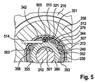
図5は、図2の制動装置140を、図1の電動工具100の自由回転時に示したものである。自由回転では、ブロッキング要素351ないし354はアクチュエータ230によって次のように位置決めされており、すなわちこれらブロッキング要素が領域514において駆動体280と接触しないように、または、この領域に沿って転動することができるように位置決めされている。従動軸210が矢印501の方向に回転運動する際、ブロッキング部材351ないし354はころ軸受のように矢印503,505,507の方向で駆動体280に沿って転動し、その結果駆動体は、矢印512の方向において従動軸210と一緒に回転する。したがって駆動体280(これに沿ってブロッキング部材351ないし354も同様に転動する)は回転せず、その結果駆動体280と相対回転不能に結合されている第2の制動要素250も回転しない。第1および第2の制動要素260,250の間に相対運動が生じないので、渦電流は発生せず、よって制動モーメントを発生させることができない。
FIG. 5 shows the
図6は、図2の制動装置140を、図1の電動工具100の制動時に示したものである。制動時には、制動装置140は図1の駆動モータ120が作動していないことにより好ましくは自動的に起動する。このような非作動時、または、制動を発生させる場合には、矢印612の方向に発生するトルク逆転に基づき、好適にはアクチュエータ230は駆動体280に対し相対的に回転する。
6 shows the
トルク逆転は、好ましくは制動の場合または図1の駆動モータ120の非作動時に、図1の差し込み工具134の慣性モーメントと駆動モータ120の摩擦モーメントとに基づいて発生する。その際、ブロッキング部材351ないし356はアクチュエータ230によって短時間制止され、したがって丸みのあるエッジ331ないし336の領域へ到達し、そこで駆動体280と駆動部材272との間でクランプされる。その際、ブロッキング部材351はたとえば第1および第2の領域621,622の間でクランプされる。これは、他のブロッキング部材352ないし356にも対応的に該当している。
Torque reversal preferably occurs based on the moment of inertia of the
このクランプにより、駆動部材272はアクチュエータ230を介して駆動体280と相対回転不能に連結され、よって従動軸210と相対回転不能に連結され、その結果駆動部材272と相対回転不能に配置されている第2の制動要素250は、矢印625で示唆したように従動軸210と一緒に回転する。これによって生じる、第2の制動要素250と、図1の電動工具100内で相対回転不能に配置されている第1の制動要素260との間の相対運動により、第2の制動要素250を、よって従動軸210を減速または制動させる制動モーメントを形成する磁気渦電流が発生する。
By this clamp, the
100 電動工具
110 ハウジング
120 駆動モータ
140 制動装置
210 従動軸
230 アクチュエータ
240 ブロッキング部材
250 第2の制動要素
251,252 第2の制動要素の端面
260 第1の制動要素
270 磁場ブレーキユニット
272 駆動部材
280 駆動体
290 連結装置
362 第1の磁極
364 第2の磁極
420 磁場
DESCRIPTION OF
Claims (15)
Applications Claiming Priority (3)
| Application Number | Priority Date | Filing Date | Title |
|---|---|---|---|
| DE102014211578.7 | 2014-06-17 | ||
| DE102014211578.7A DE102014211578A1 (en) | 2014-06-17 | 2014-06-17 | Power tool |
| PCT/EP2015/058003 WO2015192993A1 (en) | 2014-06-17 | 2015-04-14 | Electric power tool |
Publications (2)
| Publication Number | Publication Date |
|---|---|
| JP2017518892A true JP2017518892A (en) | 2017-07-13 |
| JP6189556B2 JP6189556B2 (en) | 2017-08-30 |
Family
ID=52997412
Family Applications (1)
| Application Number | Title | Priority Date | Filing Date |
|---|---|---|---|
| JP2016572807A Expired - Fee Related JP6189556B2 (en) | 2014-06-17 | 2015-04-14 | Electric tool and modular braking device for electric tool |
Country Status (5)
| Country | Link |
|---|---|
| US (1) | US10195705B2 (en) |
| JP (1) | JP6189556B2 (en) |
| CN (1) | CN106457550B (en) |
| DE (1) | DE102014211578A1 (en) |
| WO (1) | WO2015192993A1 (en) |
Families Citing this family (3)
| Publication number | Priority date | Publication date | Assignee | Title |
|---|---|---|---|---|
| JP6953252B2 (en) | 2017-09-19 | 2021-10-27 | 株式会社マキタ | Rotating tool |
| DE102018115303A1 (en) * | 2018-06-26 | 2020-01-02 | C. & E. Fein Gmbh | Gear head and hand machine tool |
| DE102019208438A1 (en) * | 2019-06-11 | 2020-12-17 | Festool Gmbh | Tooling device and method |
Citations (6)
| Publication number | Priority date | Publication date | Assignee | Title |
|---|---|---|---|---|
| JP2004072851A (en) * | 2002-08-02 | 2004-03-04 | Sumitomo Metal Ind Ltd | Eddy current reduction gear |
| JP2006181667A (en) * | 2004-12-27 | 2006-07-13 | Makita Corp | Power tool |
| JP2012020392A (en) * | 2010-07-16 | 2012-02-02 | Makita Corp | Choice structure of braking mechanism in electric power tool |
| US20140034434A1 (en) * | 2010-10-29 | 2014-02-06 | Robert Bosch Gmbh | Power Tool Braking Device |
| JP2014039361A (en) * | 2012-08-13 | 2014-02-27 | Nippon Steel & Sumitomo Metal | Eddy current type reduction gear |
| US20140124307A1 (en) * | 2011-03-18 | 2014-05-08 | Robert Bosch Gmbh | Power tool braking device |
Family Cites Families (12)
| Publication number | Priority date | Publication date | Assignee | Title |
|---|---|---|---|---|
| US3703654A (en) * | 1971-06-30 | 1972-11-21 | Ralph Karubian | Hand tool with magnetic brake |
| JPH0681487B2 (en) * | 1990-06-20 | 1994-10-12 | いすゞ自動車株式会社 | Eddy current type speed reducer |
| US5595531A (en) * | 1995-07-26 | 1997-01-21 | Ryobi North America | Random orbit sander having speed limiter |
| US6446734B1 (en) | 1999-11-11 | 2002-09-10 | Black & Decker Inc. | Motor/handle housing and gear case mounting for portable power tool |
| DE10059747A1 (en) * | 2000-12-01 | 2002-06-06 | Hilti Ag | Electric hand tool with safety clutch |
| DE60329888D1 (en) * | 2002-05-28 | 2009-12-17 | Isuzu Motors Ltd | Eddy-current deceleration device |
| CN201159251Y (en) | 2004-10-20 | 2008-12-03 | 百得有限公司 | Controller of power tool with slewing axis |
| DE102010043185A1 (en) * | 2010-10-29 | 2012-05-03 | Robert Bosch Gmbh | Machine tool braking device |
| DE102011005809A1 (en) * | 2011-03-18 | 2012-09-20 | Robert Bosch Gmbh | Machine tool braking device |
| DE102011075222A1 (en) * | 2011-05-04 | 2012-11-08 | Robert Bosch Gmbh | Machine tool braking device |
| DE102011076370A1 (en) * | 2011-05-24 | 2012-11-29 | Robert Bosch Gmbh | Machine tool braking device |
| CA2855314C (en) * | 2013-07-02 | 2017-05-09 | Taizhou Federal Robot Technology Co., Ltd. | An abrasive belt polishing finisher |
-
2014
- 2014-06-17 DE DE102014211578.7A patent/DE102014211578A1/en not_active Withdrawn
-
2015
- 2015-04-14 JP JP2016572807A patent/JP6189556B2/en not_active Expired - Fee Related
- 2015-04-14 WO PCT/EP2015/058003 patent/WO2015192993A1/en active Application Filing
- 2015-04-14 US US15/318,630 patent/US10195705B2/en not_active Expired - Fee Related
- 2015-04-14 CN CN201580032831.XA patent/CN106457550B/en not_active Expired - Fee Related
Patent Citations (6)
| Publication number | Priority date | Publication date | Assignee | Title |
|---|---|---|---|---|
| JP2004072851A (en) * | 2002-08-02 | 2004-03-04 | Sumitomo Metal Ind Ltd | Eddy current reduction gear |
| JP2006181667A (en) * | 2004-12-27 | 2006-07-13 | Makita Corp | Power tool |
| JP2012020392A (en) * | 2010-07-16 | 2012-02-02 | Makita Corp | Choice structure of braking mechanism in electric power tool |
| US20140034434A1 (en) * | 2010-10-29 | 2014-02-06 | Robert Bosch Gmbh | Power Tool Braking Device |
| US20140124307A1 (en) * | 2011-03-18 | 2014-05-08 | Robert Bosch Gmbh | Power tool braking device |
| JP2014039361A (en) * | 2012-08-13 | 2014-02-27 | Nippon Steel & Sumitomo Metal | Eddy current type reduction gear |
Also Published As
| Publication number | Publication date |
|---|---|
| WO2015192993A1 (en) | 2015-12-23 |
| CN106457550A (en) | 2017-02-22 |
| US20180161949A1 (en) | 2018-06-14 |
| DE102014211578A1 (en) | 2015-12-17 |
| US10195705B2 (en) | 2019-02-05 |
| JP6189556B2 (en) | 2017-08-30 |
| CN106457550B (en) | 2018-06-26 |
Similar Documents
| Publication | Publication Date | Title |
|---|---|---|
| US9243674B2 (en) | Power tool braking device | |
| US9360064B2 (en) | Power tool braking device | |
| TWI431904B (en) | Hollow actuator | |
| JP2016026465A (en) | Wheel-in motor and electric vehicle | |
| JP2006298251A (en) | Motor-driven wheel and vehicle | |
| JP5371456B2 (en) | Wheel drive device for vehicle | |
| JP6189556B2 (en) | Electric tool and modular braking device for electric tool | |
| WO2017077812A1 (en) | Electrically driven winch device and mobile crane | |
| JP5045321B2 (en) | Rotating electric machine with parking lock function | |
| JP5030006B2 (en) | Motor equipment | |
| JP2019172005A (en) | Vehicle driving device | |
| JP6194962B2 (en) | Motor with brake | |
| WO2017221843A1 (en) | Electric linear actuator | |
| WO2018034247A1 (en) | Electric motor device | |
| WO2013186935A1 (en) | Motor device | |
| JP2005147170A (en) | Electrically-powered braking unit | |
| JP2012080616A (en) | Variable flux motor | |
| WO2010108621A3 (en) | Electric motor | |
| JP5955237B2 (en) | Rotating electric machine with brake | |
| JP7239319B2 (en) | Braking equipment, wheel modules and locomotion mechanisms | |
| JP5772771B2 (en) | Eddy current reducer | |
| WO2019153446A1 (en) | Large-torque outer rotor motor | |
| JP3961875B2 (en) | Geared motor | |
| JP6843036B2 (en) | Rotating electric machine unit | |
| JP3802260B2 (en) | Motor with electromagnetic brake |
Legal Events
| Date | Code | Title | Description |
|---|---|---|---|
| A975 | Report on accelerated examination |
Free format text: JAPANESE INTERMEDIATE CODE: A971005 Effective date: 20170420 |
|
| TRDD | Decision of grant or rejection written | ||
| A01 | Written decision to grant a patent or to grant a registration (utility model) |
Free format text: JAPANESE INTERMEDIATE CODE: A01 Effective date: 20170711 |
|
| A61 | First payment of annual fees (during grant procedure) |
Free format text: JAPANESE INTERMEDIATE CODE: A61 Effective date: 20170802 |
|
| R150 | Certificate of patent or registration of utility model |
Ref document number: 6189556 Country of ref document: JP Free format text: JAPANESE INTERMEDIATE CODE: R150 |
|
| R250 | Receipt of annual fees |
Free format text: JAPANESE INTERMEDIATE CODE: R250 |
|
| R250 | Receipt of annual fees |
Free format text: JAPANESE INTERMEDIATE CODE: R250 |
|
| LAPS | Cancellation because of no payment of annual fees |