JP2017517433A - Steering gear - Google Patents
Steering gear Download PDFInfo
- Publication number
- JP2017517433A JP2017517433A JP2016568610A JP2016568610A JP2017517433A JP 2017517433 A JP2017517433 A JP 2017517433A JP 2016568610 A JP2016568610 A JP 2016568610A JP 2016568610 A JP2016568610 A JP 2016568610A JP 2017517433 A JP2017517433 A JP 2017517433A
- Authority
- JP
- Japan
- Prior art keywords
- pinion shaft
- gear
- steering gear
- stopper element
- bearing
- Prior art date
- Legal status (The legal status is an assumption and is not a legal conclusion. Google has not performed a legal analysis and makes no representation as to the accuracy of the status listed.)
- Granted
Links
- 239000000463 material Substances 0.000 claims description 15
- 229910000639 Spring steel Inorganic materials 0.000 description 3
- 238000006073 displacement reaction Methods 0.000 description 3
- 238000000034 method Methods 0.000 description 3
- 230000008569 process Effects 0.000 description 3
- 239000003795 chemical substances by application Substances 0.000 description 2
- 230000000694 effects Effects 0.000 description 2
- 229920001971 elastomer Polymers 0.000 description 2
- 239000000806 elastomer Substances 0.000 description 2
- 238000004519 manufacturing process Methods 0.000 description 2
- 238000003825 pressing Methods 0.000 description 2
- 230000009471 action Effects 0.000 description 1
- 230000015572 biosynthetic process Effects 0.000 description 1
- 230000008859 change Effects 0.000 description 1
- 230000008878 coupling Effects 0.000 description 1
- 238000010168 coupling process Methods 0.000 description 1
- 238000005859 coupling reaction Methods 0.000 description 1
- 238000005520 cutting process Methods 0.000 description 1
- 230000001419 dependent effect Effects 0.000 description 1
- 230000008030 elimination Effects 0.000 description 1
- 238000003379 elimination reaction Methods 0.000 description 1
- 238000010438 heat treatment Methods 0.000 description 1
- 230000010354 integration Effects 0.000 description 1
- 230000007774 longterm Effects 0.000 description 1
- 230000008092 positive effect Effects 0.000 description 1
- 230000009467 reduction Effects 0.000 description 1
- 230000000717 retained effect Effects 0.000 description 1
- 230000002441 reversible effect Effects 0.000 description 1
Images

Classifications
-
- B—PERFORMING OPERATIONS; TRANSPORTING
- B62—LAND VEHICLES FOR TRAVELLING OTHERWISE THAN ON RAILS
- B62D—MOTOR VEHICLES; TRAILERS
- B62D5/00—Power-assisted or power-driven steering
- B62D5/04—Power-assisted or power-driven steering electrical, e.g. using an electric servo-motor connected to, or forming part of, the steering gear
- B62D5/0409—Electric motor acting on the steering column
-
- F—MECHANICAL ENGINEERING; LIGHTING; HEATING; WEAPONS; BLASTING
- F16—ENGINEERING ELEMENTS AND UNITS; GENERAL MEASURES FOR PRODUCING AND MAINTAINING EFFECTIVE FUNCTIONING OF MACHINES OR INSTALLATIONS; THERMAL INSULATION IN GENERAL
- F16H—GEARING
- F16H57/00—General details of gearing
- F16H57/02—Gearboxes; Mounting gearing therein
- F16H57/021—Shaft support structures, e.g. partition walls, bearing eyes, casing walls or covers with bearings
-
- F—MECHANICAL ENGINEERING; LIGHTING; HEATING; WEAPONS; BLASTING
- F16—ENGINEERING ELEMENTS AND UNITS; GENERAL MEASURES FOR PRODUCING AND MAINTAINING EFFECTIVE FUNCTIONING OF MACHINES OR INSTALLATIONS; THERMAL INSULATION IN GENERAL
- F16H—GEARING
- F16H57/00—General details of gearing
- F16H57/02—Gearboxes; Mounting gearing therein
- F16H57/039—Gearboxes for accommodating worm gears
-
- F—MECHANICAL ENGINEERING; LIGHTING; HEATING; WEAPONS; BLASTING
- F16—ENGINEERING ELEMENTS AND UNITS; GENERAL MEASURES FOR PRODUCING AND MAINTAINING EFFECTIVE FUNCTIONING OF MACHINES OR INSTALLATIONS; THERMAL INSULATION IN GENERAL
- F16H—GEARING
- F16H57/00—General details of gearing
- F16H57/12—Arrangements for adjusting or for taking-up backlash not provided for elsewhere
-
- F—MECHANICAL ENGINEERING; LIGHTING; HEATING; WEAPONS; BLASTING
- F16—ENGINEERING ELEMENTS AND UNITS; GENERAL MEASURES FOR PRODUCING AND MAINTAINING EFFECTIVE FUNCTIONING OF MACHINES OR INSTALLATIONS; THERMAL INSULATION IN GENERAL
- F16H—GEARING
- F16H57/00—General details of gearing
- F16H57/02—Gearboxes; Mounting gearing therein
- F16H2057/02039—Gearboxes for particular applications
- F16H2057/02082—Gearboxes for particular applications for application in vehicles other than propelling, e.g. adjustment of parts
-
- F—MECHANICAL ENGINEERING; LIGHTING; HEATING; WEAPONS; BLASTING
- F16—ENGINEERING ELEMENTS AND UNITS; GENERAL MEASURES FOR PRODUCING AND MAINTAINING EFFECTIVE FUNCTIONING OF MACHINES OR INSTALLATIONS; THERMAL INSULATION IN GENERAL
- F16H—GEARING
- F16H57/00—General details of gearing
- F16H57/02—Gearboxes; Mounting gearing therein
- F16H57/021—Shaft support structures, e.g. partition walls, bearing eyes, casing walls or covers with bearings
- F16H2057/0213—Support of worm gear shafts
-
- F—MECHANICAL ENGINEERING; LIGHTING; HEATING; WEAPONS; BLASTING
- F16—ENGINEERING ELEMENTS AND UNITS; GENERAL MEASURES FOR PRODUCING AND MAINTAINING EFFECTIVE FUNCTIONING OF MACHINES OR INSTALLATIONS; THERMAL INSULATION IN GENERAL
- F16H—GEARING
- F16H57/00—General details of gearing
- F16H57/12—Arrangements for adjusting or for taking-up backlash not provided for elsewhere
- F16H2057/126—Self-adjusting during operation, e.g. by a spring
- F16H2057/127—Self-adjusting during operation, e.g. by a spring using springs
Landscapes
- Engineering & Computer Science (AREA)
- General Engineering & Computer Science (AREA)
- Mechanical Engineering (AREA)
- Chemical & Material Sciences (AREA)
- Combustion & Propulsion (AREA)
- Transportation (AREA)
- Mounting Of Bearings Or Others (AREA)
- Power Steering Mechanism (AREA)
- Gear Transmission (AREA)
- Gears, Cams (AREA)
Abstract
歯車(2)と、それに噛み合わされてピニオンシャフト(3)の長手軸(6)に対して横方向にある旋回軸周りに旋回可能に軸受けされるピニオンシャフト(3)とを有し、ピニオンシャフト(3)が、旋回軸(7)を構成してピニオンシャフト(3)に対する固定軸受(5)内に統合されるばね要素を用いて歯車(2)の方へ押し付けられ、およびピニオンシャフト(3)が、旋回軸に対して軸方向に離されて旋回軸周りのピニオンシャフト(3)の旋回を可能にするピニオンシャフト(3)の半径方向の可動性を保証するフローティング軸受(8)において軸受けされ、フローティング軸受(8)が、外側部分と外側部分に対して半径方向に可動に配置される内側部分とを含むステアリングギアは、内側部分との接触に対して設けられたストッパ面に関して異なる位置決めが可能である内側部分の半径方向の可動性を限定するストッパ要素(24)によって特徴付けられる。A pinion shaft having a gear (2) and a pinion shaft (3) that is meshed with the gear (2) and is supported so as to be pivotable about a pivot axis that is transverse to the longitudinal axis (6) of the pinion shaft (3). (3) is pressed towards the gear (2) using a spring element which constitutes the pivot axis (7) and is integrated in a fixed bearing (5) to the pinion shaft (3), and the pinion shaft (3 Bearings in the floating bearing (8) which ensures the radial mobility of the pinion shaft (3) which is axially separated from the pivot axis and allows the pinion shaft (3) to pivot about the pivot axis A steering gear is provided for contact with the inner part, the floating bearing (8) comprising an outer part and an inner part arranged radially movable relative to the outer part Characterized by a stop element (24) to limit the radial mobility of the inner portion are possible different positions with respect to stopper surface.
Description
本発明はステアリングギア、特に自動車のパワーステアリングシステムに対するステアリングギアに関する。 The present invention relates to a steering gear, and more particularly to a steering gear for a power steering system of an automobile.
殆どの自動車において、操舵中に支援トルクを生成するパワーステアリングシステムが組み込まれており、それによって車輪のステアリング旋回角を生じさせるために運転者からステアリングコラムに調達されなければならないステアリングトルクが減少する。 Most vehicles incorporate a power steering system that generates assist torque during steering, thereby reducing the steering torque that must be sourced from the driver to the steering column to produce the steering angle of the wheels. .
周知のパワーステアリングシステムは、油圧または電力駆動装置の駆動出力を変換し且つステアリングコラムに伝達するステアリングギアに基づいている。この種のステアリングギアは一般的にねじ回転ギアの形において、特にねじ歯車すなわちウォームギアとして形成され、すなわち、これは直接的または間接的にステアリングロッドに接続される歯車と、この歯車に噛み合って補助駆動装置によって駆動されるピニオンシャフトとを含む。歯車もピニオンシャフトもしばしばプラスチックによって形成される。 Known power steering systems are based on a steering gear that converts the drive output of a hydraulic or power drive and transmits it to a steering column. This type of steering gear is generally formed in the form of a screw-rotating gear, in particular as a screw gear or worm gear, i.e. it is directly or indirectly connected to a steering rod and meshed with this gear to assist And a pinion shaft driven by a driving device. Both gears and pinion shafts are often made of plastic.
部品公差、部品の異なる熱膨張に基づいて、およびステアリングギアの耐用期間の間の歯車とピニオンシャフトに対して使用された材料の摩耗もしくは設定プロセスの結果として生じるギアの遊びは、この種のステアリングギアにおける問題として指摘されてきた。特にいわゆる変更ステアリングにおいて、すなわち変化するステアリング旋回角を有して互いに直接連続するステアリングにおいて、このようなギアの遊びは、ピニオンシャフトと歯車の歯の向かい合っている側面との交互密着の結果として生じる望ましくない騒音を生成する。 Gear play caused by wear or setting processes of materials used for gears and pinion shafts based on part tolerances, different thermal expansions of parts, and during the life of the steering gear is a steering wheel of this type. It has been pointed out as a problem in gear. Especially in so-called modified steering, i.e. in steering that is directly continuous with each other with varying steering turning angles, such gear play occurs as a result of alternating contact between the pinion shaft and the opposite sides of the gear teeth. Generate unwanted noise.
この遊びは、ピニオンシャフトの長手軸に対して垂直に且つピニオンシャフトと歯車の噛み合い係合に対して一定距離において延びる軸の周りに旋回可能にピニオンシャフトが取り付けられて、且つ1つまたは複数のばね要素を用いて歯車に押し付けられる、ことによって除去されることが知られている。その場合、ピニオンシャフトの旋回性は、ピニオンシャフトが末端側で取り付けられる2つの軸受の一方に統合される。この軸受は「固定軸受」とも呼ばれる。したがって他端の領域における軸受は、旋回運動によって引き起こされる偏位を可能にするために、遊びを有して製作される(いわゆるフローティング軸受)。固定軸受は一般的に駆動装置側に設けられ、その一方でフローティング軸受はピニオンシャフトの自由端に設けられる。 This play is caused by the pinion shaft being mounted pivotably about an axis extending perpendicular to the longitudinal axis of the pinion shaft and at a distance relative to the intermeshing engagement of the pinion shaft and the gear, and one or more It is known to be removed by pressing against a gear using a spring element. In that case, the pivotability of the pinion shaft is integrated into one of the two bearings to which the pinion shaft is attached distally. This bearing is also called a “fixed bearing”. The bearings in the region at the other end are therefore produced with play (so-called floating bearings) in order to allow the displacement caused by the swivel movement. The fixed bearing is generally provided on the drive side, while the floating bearing is provided at the free end of the pinion shaft.
対応するステアリングシステムは例えば特許文献1によって知られている。そこでは、ピニオンシャフトを固定軸受の領域において収容するころ軸受が外側において2つの部分の軸受ブッシュの中に置かれる、ことが予定される。軸受ブッシュは、ころ軸受を十分に遊びなしに収容する内輪と、十分に遊びなしにステアリングギアのハウジングの穿孔内に保持される外輪とを含み、その場合、外輪と内輪は、内輪に対して外輪がねじられた際に弾性的にねじられる幅の狭いウェブを介して接続される。その場合、ウェブは旋回軸を限定するだけでなく、ばね要素としても働き、それによってピニオンシャフトは歯車の方へ押し付けられる。そのために旋回輪の組み立ては既にねじられているウェブを用いて行われる。 A corresponding steering system is known, for example, from US Pat. There, it is envisaged that a roller bearing which accommodates the pinion shaft in the area of the fixed bearing is placed on the outside in a two-part bearing bush. The bearing bush includes an inner ring that accommodates the roller bearing sufficiently without play and an outer ring that is retained in the bore of the steering gear housing without play, in which case the outer ring and the inner ring are in relation to the inner ring. It is connected via a narrow web that is elastically twisted when the outer ring is twisted. In that case, the web not only defines the pivot axis, but also acts as a spring element, whereby the pinion shaft is pressed towards the gear. For this purpose, the swivel wheel is assembled using a web that has already been twisted.
しかしまた、例えば特許文献2において開示されているように、ばね要素は歯車へのピニオンシャフトの押し付けのためにフローティング軸内に統合することも知られている。 However, it is also known that the spring element is integrated into the floating shaft for pressing the pinion shaft against the gear, for example as disclosed in US Pat.
ステアリングギア部品の製造に起因する公差も、ステアリングギアの使用の結果として発生する熱膨張と摩耗の影響もしくは設定の影響も補整できるようにするために、周知のステアリングギア装置において、ピニオンシャフトに対する相対的に大きな付勢と、それに伴うばね要素の付勢力を設けることが必要である。しかしこれは、ステアリングギアの新しい状態において、摩耗と設定の影響の補整の結果として付勢がまだ減じられていない場合、ピニオンシャフトが歯車に押し付けられる力は相対的に大きく、これは対応する大きなギア摩擦と、それに伴う効率低下に結び付く欠点を備える。これは少なくとも、許容された公差を合計で完全に利用し尽くしておらず、したがってそれに対して予定された付勢が大き過ぎるようなステアリングギアに関して認められる。 In order to be able to compensate for the tolerances caused by the manufacture of steering gear parts as well as the effects of thermal expansion and wear or settings caused as a result of the use of the steering gear, in known steering gear devices, relative to the pinion shaft Therefore, it is necessary to provide a large biasing force and a biasing force of the spring element associated therewith. However, this means that in the new state of the steering gear, if the bias is not yet reduced as a result of compensation for wear and setting effects, the force with which the pinion shaft is pressed against the gear is relatively large, which corresponds to a correspondingly large It has the drawbacks associated with gear friction and associated efficiency reduction. This is at least allowed for steering gears that do not fully utilize the allowable tolerances in total, and therefore the energies envisaged for them are too great.
この従来技術から出発して、本発明は自動車のパワーステアリングシステムに対する改善されたステアリングギアを提示する課題に基礎を置く。特に、新しい状態におけるその摩擦損失ができる限り小さくなるステアリングギアを提示する意図に基づいている。 Starting from this prior art, the present invention is based on the task of presenting an improved steering gear for an automotive power steering system. In particular, it is based on the intention to present a steering gear whose friction loss in the new state is as small as possible.
この課題は、特許請求項1の対象物によって解決される。有利な実施形態は更なる特許請求項の対象物であり、および本発明の以下の説明によって明らかにされる。
This problem is solved by the object of
本発明はステアリングギアの作動によって、熱膨張と摩耗および設定プロセスの結果として生じるギアの遊びの補整に対して、ちょうど十分な大きさに量定されるピニオンシャフトの相対的に弱い付勢を設けることは、しかし都合の悪い部品公差において原理的にギアの遊びをもたらす可能性がある、という考えを基礎に置いている。したがってこのような公差に基づくギアの遊びを回避するために、さらにギアの遊びの補整のために付勢を用いて支援的に働く付加的な措置が設けられる。 The present invention provides a relatively weak bias of the pinion shaft that is sized just enough to compensate for thermal expansion and wear and gear play resulting from the setting process by actuation of the steering gear. This is based on the idea that in principle, however, it can lead to gear play at inconvenient component tolerances. Therefore, in order to avoid gear play based on such tolerances, additional measures are provided to assist in the use of bias to compensate for gear play.
そのために、歯車とそれに噛み合うピニオンシャフトとを有する一般的なステアリングギアにおいて、該ピニオンシャフトはピニオンシャフトの長手軸に対して横方向の、特に垂直な旋回軸周りに旋回可能に軸受され、その場合、ピニオンシャフトは、ピニオンシャフトに対する固定軸受に統合されたばね要素を用いて歯車に対して押し付けられ、およびピニオンシャフトは旋回軸に対して軸方向に距離を置いてフローティング軸受において軸受され、該フローティング軸受は旋回軸周りのピニオンシャフトの旋回を可能にするピニオンシャフトの半径方向の可動性を保証し、その場合、フローティング軸受は望ましくはステアリングギアのハウジング内に置かれる外側部分、特に外輪と、外側部分に対して可動の内側部分、特に内輪とを含み、本発明に基づいて、内側部分の半径方向の可動性を限定するストッパ要素が設けられ、該ストッパ要素は内側部分との接触に対して設けられるストッパ面に関して異なった位置決めが可能である、ことが予定される。 For this purpose, in a general steering gear having a gear and a pinion shaft meshing therewith, the pinion shaft is pivotally supported around a pivot axis that is transverse to the longitudinal axis of the pinion shaft, in particular in the case of a vertical axis. The pinion shaft is pressed against the gears using a spring element integrated in a fixed bearing to the pinion shaft, and the pinion shaft is bearing in the floating bearing at an axial distance from the pivot axis, the floating bearing Ensures the radial movement of the pinion shaft which allows the pinion shaft to pivot about the pivot axis, in which case the floating bearing is preferably placed on the outer part of the steering gear housing, in particular the outer ring and the outer part. Inwardly movable parts, especially inner rings In accordance with the present invention, a stopper element is provided which limits the radial mobility of the inner part, which can be positioned differently with respect to the stopper surface provided for contact with the inner part, Is scheduled.
ストッパ要素によって、外側部分および/またはハウジングに対する内側部分の半径方向の可動性は、それぞれ部品公差に依存して、ばね要素による弱い付勢のみにも拘らず、ステアリングギアの作動中のギアの遊びは、ストッパ要素へのフローティング軸受の内側部分の当接によって回避されるように、個別に制限される。それに伴って具体的に、ステアリングギアの組み立ての際に公差に基づくギアの遊びを付勢を用いて補整することができる。その場合、ステアリングギアはまだ作動しておらず、且つ加えてギアの遊びには傾向的に増大する設定現象または摩耗現象もまだ現れていないので、それに対して弱い付勢のみで十分である。その場合、ストッパ要素が内輪に密着して位置決めされ且つ固定されることにより、ストッパ要素によってステアリングギアのバックラッシュは組み立ての際に確保される(封じ込まれる)。したがって、公差の枠内にある異なる寸法に依存しないで、作動中に発生するギアの遊びを除去することも比較的弱い付勢で十分である。そのようにして得ることができる比較的弱い付勢は、対応する僅かなギア摩擦と、したがって対応する僅かな摩擦損失をもたらす。 Due to the stopper element, the radial movability of the outer part and / or the inner part relative to the housing is dependent on component tolerances, in spite of only a weak biasing by the spring element, and the gear play during operation of the steering gear. Are restricted individually so that they are avoided by abutment of the inner part of the floating bearing on the stopper element. Accordingly, specifically, the play of the gear based on the tolerance can be compensated by using the bias when the steering gear is assembled. In that case, the steering gear is not yet operated, and in addition, a setting phenomenon or a wear phenomenon that tends to increase in gear play has not yet appeared, so only a weak bias against it is sufficient. In this case, the stopper element is positioned and fixed in close contact with the inner ring, whereby the backlash of the steering gear is secured (sealed) by the stopper element during assembly. Thus, a relatively weak bias is sufficient to eliminate gear play that occurs during operation without depending on the different dimensions within the tolerance frame. The relatively weak bias that can be obtained in this way results in a corresponding little gear friction and thus a corresponding little friction loss.
付勢によって行われるギアの遊びの除去はストッパ要素を用いて確保され、したがってこれは、ピニオンシャフトと歯車との係合の逆である(ピニオンシャフトの長手軸に対して)半径方向への可動性に対するストッパとして利用されなければならないので、望ましくは、ストッパ要素を歯車とピニオンシャフトとの係合に向かい合うピニオンシャフトの側面に配置する、ことを予定することができる。 The elimination of gear play caused by the biasing is ensured by means of a stopper element, so this is the reverse of the engagement of the pinion shaft and the gear (relative to the longitudinal axis of the pinion shaft) in the radial direction. Since it has to be used as a stopper against sexuality, it can be envisaged that the stopper element is preferably arranged on the side of the pinion shaft facing the engagement of the gear and the pinion shaft.
望ましくは、ストッパ要素を用いてスアテアリングギアの組み立ての際に付勢によって行われる公差に基づくギアの遊びの除去のみが確保されて、したがってこれは後から追加してその位置に関して最早変更する必要がないことが予定されるので、ストッパ要素はこの位置決めを一回のみ行うことができ、且つその後で最早変更することができないように形成されれば、十分であることが可能である。これは比較的低コストで且つ扱い易いストッパ要素の形態を可能にする。 Desirably, only removal of gear play based on tolerances made by biasing when assembling the steering gear using the stopper element is ensured, so this needs to be added later and changed anymore with respect to its position. It is possible that it is sufficient if the stop element is formed such that this positioning can only take place once and can no longer be changed thereafter. This allows a form of stopper element which is relatively inexpensive and easy to handle.
特にストッパ要素は、内側部分に接触し望ましくは予定された力において十分に変形不能な接触部分と、支持要素をハウジングおよび/または外側部分に固定する支持部分とを含む、ことを予定することができる。 In particular, the stop element may be intended to include a contact portion that contacts the inner portion and preferably is not sufficiently deformable at a predetermined force, and a support portion that secures the support element to the housing and / or the outer portion. it can.
その場合、ストッパ要素の異なる位置決めは、望ましくは、支持部分が硬化可能な材料、特に適当なプラスチックによって形成される、ことによって達成することができる。それによって、ステアリングギアの組み立ての間に、ストッパ要素は、これが少なくとも遊びなしにフローティング軸受の内側部分に密着し、且つ次にストッパ要素のこの位置が、特にフローティング軸受の外側部分および/またはステアリングギアのハウジングへの材料接続、摩擦接続、および/または形状接続によるストッパ要素の接続をもたらすことができる支持部分の材料の硬化によって確保される、ように位置決めすることができる。 In that case, different positioning of the stopper element can be achieved, preferably by the support part being made of a curable material, in particular a suitable plastic. Thereby, during the assembly of the steering gear, the stopper element adheres to the inner part of the floating bearing, at least without play, and then this position of the stopper element is in particular the outer part of the floating bearing and / or the steering gear. Can be positioned as ensured by hardening of the material of the support part, which can result in a connection of the stopper element by a material connection, friction connection and / or shape connection to the housing.
支持部分の硬化可能な材料は、例えば、硬化が温度変化によって、したがって熱供給または熱除去によって獲得されるように形成することができる。また、望ましい硬化をもたらす光波、例えば紫外線または赤外線による材料の照射が望ましい硬化をもたらすことを予定することができる。さらに、材料に、ストッパ要素の組み立て前に硬化剤が供給されること、ストッパ要素の組み立てに対して自由に使用できる時間の中で硬化を生じることを予定することもできる。 The curable material of the support portion can be formed, for example, such that curing is obtained by a temperature change and thus by heat supply or heat removal. Also, it can be expected that irradiation of the material with light waves, such as ultraviolet or infrared, that provides the desired cure will result in the desired cure. Furthermore, it is possible to schedule the material to be supplied with a curing agent prior to the assembly of the stopper element and to cure in a time that can be used freely for the assembly of the stopper element.
ストッパ要素の位置決めを永続的に確保するために、望ましくは、ストッパ要素とフローティング軸受の外側部分および/またはハウジングとの間の接続が形状接続的に(も)形成されることを予定することができる。そのような形状接続的な接続は、硬化可能な材料から成る支持部分の形態において、ハウジングおよび/またはフローティング軸受の外側部分が、その中に支持部分の材料を非硬化状態において侵入させ、そこで硬化させることができる窪みを形成する場合に、簡単な方法において実現することができる。そのような窪みは、例えば周囲を取り巻く溝の形状において形成することができる。 In order to permanently ensure the positioning of the stopper element, it may be desirable that the connection between the stopper element and the outer part of the floating bearing and / or the housing is (also) formed in a shape-connective manner. it can. Such a shape-connective connection is in the form of a support part made of a curable material, in which the housing and / or the outer part of the floating bearing penetrates the material of the support part in an uncured state, where it hardens. In the case of forming a recess that can be made, it can be realized in a simple manner. Such a depression can be formed, for example, in the shape of a groove surrounding the periphery.
異なる位置においてフローティング軸受の外側部分および/またはハウジングに接続できるストッパ要素は、例えば外側部分および/またはハウジングの内ねじに異なる幅でねじ込むことができ、且つ選択された位置において自動ロックによって、および/または例えばロックねじのような独立した支持要素によって確保されるねじボルトの形状において形成されることができる。 Stop elements which can be connected to the outer part of the floating bearing and / or the housing in different positions can be screwed with different widths, for example, into the outer part and / or the inner thread of the housing, and with automatic locking in selected positions and / or Or it can be formed in the form of a screw bolt secured by an independent support element, for example a locking screw.
また、外側部分および/またはステアリングギアのハウジングの開口部への圧入による摩擦接続によって異なる位置に固定できる鋲状のストッパ要素の利用も可能である。 It is also possible to use hook-shaped stopper elements that can be fixed in different positions by frictional connection by press-fitting into the outer part and / or the opening of the steering gear housing.
本発明に基づくステアリングギアの好ましい一形態において、固定軸受がばね要素の統合に対して、望ましくはリング状の外側部分と、外側部分の内部に配置される望ましくはリング状の内側部分とを備える軸受ブッシュを含み、その場合、外側部分と内側部分は旋回軸の形成のために、内側部分に対する外側部分の相対ねじりを可能にする少なくとも1つのウェブを介して接続され、その場合、ウェブは弾性的に変形可能に形成され、その結果、ねじり棒ばねの作用を備える、ことを予定することができる。 In a preferred form of the steering gear according to the invention, the fixed bearing comprises, for the integration of the spring element, preferably a ring-shaped outer part and a preferably ring-shaped inner part arranged inside the outer part. Including a bearing bush, in which case the outer part and the inner part are connected via at least one web allowing the relative twisting of the outer part with respect to the inner part for the formation of a pivot, in which case the web is elastic It can be planned to be deformable and thus have the action of a torsion bar spring.
不定冠詞(「ein(1つ)」、「eine(1つ)」、「einer(1つの)」および「eines(1つの)」)は、特に特許請求項において、および特許請求項を一般的に説明する明細書において、「このような」と解釈すべきであり、「数詞」として解釈すべきではない。したがって、対応してそれを用いて具体的に述べられる構成要素は、これは少なくとも一回存在することができ且つ複数回存在することができると解釈されなければならない。 Indefinite articles (“ein”, “eine”, “einer” and “eines”) are particularly in the claims and the claims in general. Should be construed as “such”, and not as “numerical”. Accordingly, a component specifically described using it correspondingly should be construed that it can exist at least once and can exist multiple times.
本発明を以下、図に示した実施例に基づいて詳細に説明する。 The present invention will be described in detail below based on the embodiments shown in the drawings.
図1は、自動車のパワーステアリングに対する本発明に基づくステアリングギアの一実施形態の基本的な構成要素を示す。これは複数部分から成るハウジング1を含み、その中に歯車2、および歯車2に噛み合うピニオンシャフト3が回転可能に配置される。歯車2は自動車のステアリングコラム4に固定して接続される。
FIG. 1 shows the basic components of an embodiment of a steering gear according to the invention for power steering of an automobile. This includes a
ピニオンシャフト3は駆動装置側の末端を備え、該末端を介してこれは示されていない駆動装置(例えば電気モータ)の出力シャフトに接続可能である。この駆動装置側の末端の領域において、ピニオンシャフト3は固定軸受5を用いてハウジング1内に軸受けされる。固定軸受5は、これが基本的にハウジング1に対する相対的なピニオンシャフト3の並進を許容せず、しかしピニオンシャフト3の長手軸6に対して垂直に調整された旋回軸7周りの旋回を許容するように形成される。
The
この旋回は駆動装置側末端に向かい合うピニオンシャフト3の自由末端の偏位を生じさせ、該ピニオンシャフト3はそこでハウジング1の対応する収容部内のフローティング軸受8を用いて軸受される。このフローティング軸受8は、旋回によって生じるピニオンシャフト3の自由末端の偏位を許容するように形成される。
This swiveling causes a displacement of the free end of the
固定軸受5もフローティング軸受8もそれぞれころ軸受9、10を含み、該ころ軸受においてピニオンシャフト3の対応する部分が十分に遊びなしに軸受けされる。ころ軸受9、10自体はそれぞれ軸受ブッシュ11、12内に軸受けされ、該軸受ブッシュは再び十分に遊びなしに対応するハウジング1の収容部内に配置される。軸受ブッシュ11、12は構造的に、固定軸受5のケースにおいて、これが旋回軸7周りのピニオンシャフト3の旋回を可能にするように、およびフローティング軸受8のケースにおいて、ピニオンシャフト3の自由末端の偏位を可能にするように形成される。
Both the fixed
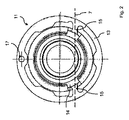
そのために固定軸受5の軸受ブッシュ11は、例えばばね鋼から成る外輪13の形状における外側部分と、例えば同様にばね鋼から成る内輪14の形状における内側部分とを含む(図2参照)。外輪13は、(例えばばね鋼から成る)2つのウェブ15を介して内輪14に接続され、その場合、2つのウェブ15は主として共線的に延伸し、且つそれによって内輪14が外輪13に対して相対的に旋回することができるように旋回軸7を形成する。
For this purpose, the bearing
さらに、固定軸受5の軸受ブッシュ11の外輪13において、一方側面に突起16が、および反対側面に窪み17が形成される。これらは、ハウジング1内における軸受ブッシュ11の、およびそれに伴って固定軸受5の一義的な位置決めに利用される。そのためにハウジング1は対応する対向輪郭を備える。
Further, in the
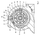
図3は、フローティング軸受8の領域におけるステアリングギアの断面を示す。フローティング軸受8の軸受ブッシュ12の本質的な機能は、固定軸受5に形成される旋回軸7周りのその旋回の結果としてのピニオンシャフト3の自由末端の偏位を許容することにある。そのために軸受ブッシュ12は同様に外輪18の形状による外側部分と、内輪19の形状による内側部分とを含む。一部分において、内輪19は継手20を介して外輪18に接続される。継手20の領域において外輪18と内輪19の部分が接触し、その場合、この部分がエラストマリング21によって取り囲まれる。この形態によって、(旋回)継手20は、継手20の領域にある旋回軸周りの外輪18に対する相対的な内輪19の旋回を可能にする僅かな旋回トルクを有して形成される。この旋回運動において、外輪18と内輪19は接触部分において互いに滑り、もしくは転がり、一方においてエラストマリング21は内輪19に対する外輪18のこの相対運動を許容し、且つ付加的にその結合を保証する。
FIG. 3 shows a cross section of the steering gear in the region of the floating
フローティング軸受8の軸受ブッシュ12は、固定軸受5内に形成される旋回軸7周りのピニオンシャフト3の旋回が、基本的に継手20を通って導かれる半径方向軸に対して垂直に形成される軸受ブッシュ12のその半径方向軸22方向における外輪18に対する相対的な内輪19の移動をもたらすように、ステアリングギアのハウジング1内に統合される、ことが予定される。ステアリングギアの作動中において歯車2にピニオンシャフト3が交差することをできる限り回避するために、継手20を通って導かれる軸受ブッシュ12の半径方向軸の方向において、それに対してできる限り内輪19に対する外輪18の移動可能性を不可能にしなければならない。これは、継手20に半径方向に向かい合う軸受ブッシュ12の部分における内輪19と外輪18の間の間隔が、例えば0.1mmの比較的小さい寸法に制限されることによって達成される。これは、半径方向に移動可能に外輪18の内部に置かれる制限要素23を用いて行われる。制限要素23は、外輪18の半径方向の幅よりも大きい半径方向の幅を備える。それによって、まだハウジング1内に取り付けられていない軸受ブッシュ12の制限要素23は、図3に示されているように、これが外輪18の外面より突き出す幅だけ外側へ移動させられ、その結果、内輪19の外側と制限要素23の間の相対的に大きな間隔が生じる。
The bearing
次に制限要素23による外輪18の外面からの突き出しは、ハウジング1と衝突する結果として最早不可能であり、したがって制限要素23が取り付けに対して半径方向に内側へ移動しなければならないので、この間隔はハウジング1内への軸受ブッシュ12の取り付けの際に望ましい寸法に減少させられる。
Next, the protrusion of the
フローティング軸受8に対して、本発明に基づいて、ピニオンシャフト3と歯車2との係合の反対側のピニオンシャフト3の側面に配置されるストッパ要素24が設けられる。ストッパ要素24は、フローティング軸受8の軸受ブッシュ12の内輪19に接触する接触部分25と、ハウジング1の収容開口部27の内部に固定可能である支持部分26とを含む。フローティング軸受8の軸受ブッシュ12の内輪19とのストッパ要素24の接触を可能にするために、外輪18は対応する貫通開口部28を備える。ストッパ要素24は、公差に基づくギアの遊びを除去すること、もしくはそのようなギアの遊びの除去を確実にすることに対して設けられる。そのためにストッパ要素24は、(新しい)ステアリングギアの組み立ての際に、これが正面側に形成されたストッパ面31を用いて内輪19に遊びなしに密着するように、および場合によっては僅かに内輪19を押すように位置決めされる。そのために、複数の同一ステアリングギアにおいて、部品の製造起因および組み立て起因の公差に基づいて、ハウジング1のそれに付属する収容開口部27内におけるストッパ要素24の異なる位置が必要である。ストッパ要素24は、これがステアリングギアの組み立ての際に収容開口部27内に対応して位置決めされることによって、この異なる位置でのハウジング1における固定を可能にし、その場合、ストッパ要素24の支持部分26の材料はまだ硬化しておらず、したがって変形が可能である。したがって支持部分26の材料は、収容開口部27の壁に形成された周囲を取り巻く溝の形状における窪み29に侵入することができる。それに続く、例えば加熱によって、光の照射によって、または事前に添加される硬化剤によっても、硬化時間の終了を待つことによって行うことができる支持部分26の材料の硬化によって、ハウジング1の収容開口部27におけるストッパ要素24の材料接続および形状接続による固定が実現され、それによってストッパ要素24は永続的に位置確保される。ピニオンシャフト3に対して、ピニオンシャフト3が旋回可能に軸受されて且つばね荷重されて歯車2に向かって押し付けられることによって獲得される付勢が予定され、その場合、ばね荷重は、旋回軸7の形成と全く同様に、内輪14に対する外輪13の相対ねじれの結果としてねじられ、したがって機能的にねじりばねウェブとして働く固定軸受5の軸受ブッシュ11のウェブ15によって実現される。この付勢によって、一方において本発明に基づく各ステアリングギアが、公差に基づく寸法公差、形状公差および位置公差にもかかわらず、新しい状態において基本的にギアの遊びを備えないことを保証することができる。その場合、そのバックラッシュは、ストッパ要素24がフローティング軸受8の内輪19に密着して収容開口部27内に固定されることによって、組み立ての際にストッパ要素24を用いて確保される。
In accordance with the present invention, the floating
さらに、ピニオンシャフト3の付勢は、ステアリングギアの作働中に部品の異なる熱膨張の結果として短期間に生じる、およびピニオンシャフト3と歯車2の材料の摩耗と設定プロセスによって長期間に生じるギアの遊びの補整をもたらす。しかし、耐用期間の枠内において予想される作動に起因する最大のギアの遊びは、特に部品に対して許容される公差の不利な総和において生じるであろうギアの遊びに比較して相対的に小さい。したがって、ストッパ要素24を用いて公差に起因するギアバックラッシュの確保を可能にすることによって、付勢は相対的に弱く設計することができる。これは、特にステアリングギアの新しい状態において、それに対応するより少ないギア摩擦に特に良い影響をもたらす。
Furthermore, the biasing of the
さらに、フローティング軸受8の軸受ブッシュ12の外輪18は、ピニオンシャフト3の旋回の際に図1および3において上方への内輪19の動きを制限する追加ストッパ要素30を含む。この追加ストッパ要素30はステアリングギアの正常な作動において内輪19に接触しない。もっと正確に言えば、これは、ステアリングギアの作動中の酷使状態における噛み合い力のみを内輪19のぶつかりによって支え、且つそれによってストッパ要素24の過負荷を回避する意図に基づいている。
In addition, the
図には示していない本発明に基づくステアリングギアの代替形態において、ストッパ要素24はフローティング軸受8のころ軸受10の外輪に接触し、そのために軸受ブッシュ12の内輪19は対応する開口部を備えることができる、ことを予定することができる。このケースにおいて、ころ軸受10の外輪、もしくはころ軸受10全体は、特許請求項において定義されている本発明に基づくステアリングギアの内側部分を意味する。
In an alternative form of the steering gear according to the invention not shown in the drawing, the
そのために別の変形も同様に可能である。すなわち、ハウジング1の一部分を外側部分として、およびピニオンシャフト3の一部分を特許請求項において定義された本発明に基づくステアリングギアの内側部分として予定する可能性も存在する。
For this reason, other variations are possible as well. That is, there is also the possibility of planning a part of the
1 ハウジング
2 歯車
3 ピニオンシャフト
4 ステアリングコラム
5 固定軸受
6 ピニオンシャフトの長手軸
7 旋回軸
8 フローティング軸受
9 固定軸受のころ軸受
10 フローティング軸受のころ軸受
11 固定軸受の軸受ブッシュ
12 フローティング軸受の軸受ブッシュ
13 固定軸受の軸受ブッシュの外輪
14 固定軸受の軸受ブッシュの内輪
15 ウェブ
16 突起
17 窪み
18 フローティング軸受の軸受ブッシュの外輪
19 フローティング軸受の軸受ブッシュの内輪
20 継手
21 エラストマリング
22 半径方向軸
23 制限要素
24 ストッパ要素
25 接触部分
26 支持部分
27 収容開口部
28 貫通開口部
29 窪み
30 追加ストッパ要素
31 ストッパ面
DESCRIPTION OF
Claims (8)
前記ピニオンシャフト(3)は、前記旋回軸(7)を構成して前記ピニオンシャフト(3)に対する固定軸受(5)内に統合されるばね要素を用いて前記歯車(2)の方へ押し付けられ、および前記ピニオンシャフト(3)は、前記旋回軸(7)に対して軸方向に離されて、前記旋回軸(7)周りの前記ピニオンシャフト(3)の旋回を可能にし、前記ピニオンシャフト(3)の半径方向の可動性を保証するフローティング軸受(8)において軸受けされ、
前記フローティング軸受(8)は、外側部分と、前記外側部分に対して半径方向に可動に配置される内側部分とを含む、ステアリングギアであって、
前記内側部分との接触に対して設けられたストッパ面(31)に関して異なる位置決めが可能である前記内側部分の半径方向の可動性を限定するストッパ要素(24)を有する、ことを特徴とするステアリングギア。 A gear (2), and a pinion shaft (3) that is meshed with the gear (2) and is pivotally supported around a pivot axis (7) that is transverse to the longitudinal axis (6) of the pinion shaft (3). ,
The pinion shaft (3) is pressed towards the gear (2) using a spring element that constitutes the pivot axis (7) and is integrated in a fixed bearing (5) with respect to the pinion shaft (3). And the pinion shaft (3) is axially separated from the pivot axis (7) to allow the pinion shaft (3) to pivot about the pivot axis (7). 3) bearings in the floating bearing (8) ensuring the radial mobility;
The floating bearing (8) is a steering gear including an outer part and an inner part arranged to be movable in a radial direction with respect to the outer part,
Steering, characterized in that it has a stopper element (24) that limits the radial mobility of the inner part which can be positioned differently with respect to the stopper surface (31) provided for contact with the inner part. gear.
Applications Claiming Priority (3)
| Application Number | Priority Date | Filing Date | Title |
|---|---|---|---|
| DE102014107073.9A DE102014107073A1 (en) | 2014-05-20 | 2014-05-20 | steering gear |
| DE102014107073.9 | 2014-05-20 | ||
| PCT/EP2015/057503 WO2015176866A1 (en) | 2014-05-20 | 2015-04-07 | Steering gear |
Publications (2)
| Publication Number | Publication Date |
|---|---|
| JP2017517433A true JP2017517433A (en) | 2017-06-29 |
| JP6490718B2 JP6490718B2 (en) | 2019-03-27 |
Family
ID=52814987
Family Applications (1)
| Application Number | Title | Priority Date | Filing Date |
|---|---|---|---|
| JP2016568610A Active JP6490718B2 (en) | 2014-05-20 | 2015-04-07 | Steering gear |
Country Status (5)
| Country | Link |
|---|---|
| US (1) | US10315687B2 (en) |
| JP (1) | JP6490718B2 (en) |
| CN (1) | CN106458251B (en) |
| DE (1) | DE102014107073A1 (en) |
| WO (1) | WO2015176866A1 (en) |
Cited By (1)
| Publication number | Priority date | Publication date | Assignee | Title |
|---|---|---|---|---|
| WO2019163278A1 (en) * | 2018-02-23 | 2019-08-29 | 日立オートモティブシステムズ株式会社 | Rear wheel control device |
Families Citing this family (10)
| Publication number | Priority date | Publication date | Assignee | Title |
|---|---|---|---|---|
| DE102015000928B3 (en) * | 2015-01-28 | 2016-07-21 | Thyssenkrupp Ag | Device for introducing an auxiliary torque in a steering shaft of an electromechanical power steering system |
| US10351167B2 (en) | 2015-12-09 | 2019-07-16 | Steering Solutions Ip Holding Corporation | Steering system with magnetic torque overlay lash compensation |
| DE102016211694B3 (en) * | 2016-06-29 | 2017-10-05 | Ford Global Technologies, Llc | Transmission unit for a motor vehicle |
| DE102016212913A1 (en) * | 2016-07-14 | 2018-01-18 | Volkswagen Aktiengesellschaft | Arrangement of an annular bearing for a functionally coupled to an auxiliary motor motor shaft in a motor shaft housing |
| GB201616486D0 (en) * | 2016-09-28 | 2016-11-09 | Trw Limited | A gearbox assembly for an electric power steering apparatus |
| DE102017209563A1 (en) * | 2017-06-07 | 2018-12-13 | Robert Bosch Gmbh | Floating bearing, steering gear and steering system |
| DE102017211461B4 (en) * | 2017-07-05 | 2024-06-27 | Robert Bosch Gmbh | Steering gear |
| DE102018201858A1 (en) * | 2018-02-07 | 2019-08-29 | Robert Bosch Gmbh | Steering gear, steering system and method for producing a swivel ring for a steering gear |
| DE102018207766A1 (en) * | 2018-05-17 | 2019-11-21 | Robert Bosch Gmbh | Steering gear and method for producing the steering gear |
| CN109780054A (en) * | 2019-01-28 | 2019-05-21 | 宁波易锐汽车零部件有限公司 | A kind of plastic bearing bushing and its manufacturing method |
Citations (8)
| Publication number | Priority date | Publication date | Assignee | Title |
|---|---|---|---|---|
| JP2002067992A (en) * | 2000-09-04 | 2002-03-08 | Koyo Seiko Co Ltd | Motor-driven power steering device |
| WO2003047948A1 (en) * | 2001-12-03 | 2003-06-12 | Nsk Ltd. | Electric power steering device |
| JP2010228671A (en) * | 2009-03-27 | 2010-10-14 | Showa Corp | Electric power steering device |
| JP2011020645A (en) * | 2009-07-17 | 2011-02-03 | Showa Corp | Electric power steering device |
| US20120125132A1 (en) * | 2009-05-08 | 2012-05-24 | Zf Lenksysteme Gmbh | Bearing system for a worm in a steering gear |
| JP2013520626A (en) * | 2010-02-24 | 2013-06-06 | ツェットエフ、レンクジステメ、ゲゼルシャフト、ミット、ベシュレンクテル、ハフツング | Helical gear device for automobile steering system |
| JP2013524112A (en) * | 2010-03-26 | 2013-06-17 | ツェットエフ、レンクジステメ、ゲゼルシャフト、ミット、ベシュレンクテル、ハフツング | Helical gear device for automobile steering system |
| JP2014185728A (en) * | 2013-03-25 | 2014-10-02 | Showa Corp | Gear preload structure and electric power steering device |
Family Cites Families (36)
| Publication number | Priority date | Publication date | Assignee | Title |
|---|---|---|---|---|
| US656310A (en) * | 1899-12-08 | 1900-08-21 | Frederic James Warburton | Bearing for shafts. |
| US829658A (en) * | 1905-12-01 | 1906-08-28 | Benjamin F Leavitt | Automatic lock for bearings. |
| US1165432A (en) * | 1913-09-25 | 1915-12-28 | Onesime E Michaud | Antifriction-bearing. |
| US1366089A (en) * | 1919-10-30 | 1921-01-18 | Leinert Wenzel | Bearing |
| US1758479A (en) * | 1928-02-18 | 1930-05-13 | John H Zahn | Adjustable roller bearing |
| US2355901A (en) * | 1940-12-06 | 1944-08-15 | Pantex Pressing Machine Inc | Backlash resisting locking setscrew |
| US3326313A (en) * | 1966-06-09 | 1967-06-20 | American Coleman Company | Adjustment means for the pivot bearings of steerable drive wheels |
| DE2532370A1 (en) * | 1975-07-19 | 1977-01-20 | Ford Werke Ag | PROCEDURE FOR PRECISE ADJUSTMENT OF TAPED ROLLER BEARINGS |
| US4700582A (en) * | 1985-05-31 | 1987-10-20 | Ford Motor Company | Anti-backlash gear mechanism |
| JPS62127545A (en) * | 1985-11-26 | 1987-06-09 | Aisin Seiki Co Ltd | Driving device for power sheet |
| AU5717096A (en) * | 1995-05-01 | 1996-11-21 | Mcdonnell Douglas Corporation | Preparation of pre-coated aluminum alloy articles |
| US6016716A (en) * | 1996-06-18 | 2000-01-25 | Mauro; George | Anti-backlash mechanism for a rotary stage |
| FR2771469B1 (en) * | 1997-11-27 | 2000-02-04 | Meritor Light Vehicle Sys Ltd | GEAR MOTOR FOR DRIVING VEHICLE EQUIPMENT SUCH AS A WINDOW REGULATOR WITH REMOVAL OF THE AXIAL CLEARANCE OF ITS SHAFT LINE |
| JP2001080529A (en) * | 1999-07-15 | 2001-03-27 | Koyo Seiko Co Ltd | Power steering gear and power transmission joint |
| FR2808759B1 (en) * | 2000-05-10 | 2005-08-26 | Koyo Seiko Co | POWER ASSISTED STEERING APPARATUS |
| JP3653611B2 (en) * | 2000-05-18 | 2005-06-02 | 光洋精工株式会社 | Electric steering device |
| DE10051306A1 (en) * | 2000-10-17 | 2002-04-18 | Bosch Gmbh Robert | Gear for a motor vehicle steering assembly used e.g. in a servo unit of an electrical power-assisted steering arrangement comprises a pinion arranged on a shaft so that it does not rotate, and a toothed wheel interacting with the pinion |
| US20050150372A1 (en) * | 2002-07-08 | 2005-07-14 | Danh Luan Nguyen | Thrust device |
| ES2254947T3 (en) * | 2002-07-08 | 2006-06-16 | Zf Lenksysteme Gmbh | TIGHTENING DEVICE. |
| JP4356485B2 (en) * | 2004-03-09 | 2009-11-04 | 株式会社ジェイテクト | Electric power steering device |
| US7082691B2 (en) * | 2004-04-28 | 2006-08-01 | Trimble Navigation Limited | Laser level rotor assembly addressing angular drift |
| DE602005010415D1 (en) * | 2004-05-07 | 2008-11-27 | Timken Co | STORAGE ARRANGEMENT FOR WIND TURBINE GEAR SHAFT |
| JP4872372B2 (en) * | 2006-02-14 | 2012-02-08 | 株式会社ジェイテクト | Electric power steering device |
| US7524390B2 (en) * | 2006-03-27 | 2009-04-28 | The Penn State Research Foundation | Fixture and method of holding and debonding a workpiece with the fixture |
| DE102007055814A1 (en) * | 2007-12-14 | 2009-06-18 | Zf Lenksysteme Gmbh | Radially movable bearing |
| DE102008002769A1 (en) | 2008-02-12 | 2009-08-20 | Zf Lenksysteme Gmbh | Helical bevel gear, particularly worm gear for electrical power steering for motor vehicle, has screw bevel connected with drive shaft of electrical driving motor and screw bevel is arranged in transmission case |
| US20090314114A1 (en) * | 2008-06-18 | 2009-12-24 | Elram Engineering And Advanced Technologies 1992 Ltd. | Backlash elimination mechanism for gear systems for low speed applications |
| WO2011044428A2 (en) * | 2009-10-09 | 2011-04-14 | Dresser-Rand Company | Auxiliary bearing system for magnetically supported rotor system |
| DE102009054655A1 (en) | 2009-12-15 | 2011-06-16 | Zf Lenksysteme Gmbh | Steering gear with fixed bearing and floating bearing for screw pinion |
| JP6130988B2 (en) * | 2011-03-22 | 2017-05-17 | Kyb株式会社 | Power steering device |
| JP2013071679A (en) * | 2011-09-28 | 2013-04-22 | Showa Corp | Electric power steering device |
| JP5999423B2 (en) | 2011-11-25 | 2016-09-28 | 株式会社ジェイテクト | Electric power steering device |
| DE102012102665A1 (en) | 2012-03-28 | 2013-10-02 | Zf Lenksysteme Gmbh | Device for pressing screw or sprocket on worm wheel or screw gear, for use in electric power steering system of motor car, has pressure element whose axial movement relative to adjusting element is realized in direction of gear |
| DE102012103147A1 (en) | 2012-04-12 | 2013-10-17 | Zf Lenksysteme Gmbh | LOS BEARING FOR A STEERING GEAR |
| JP5908380B2 (en) * | 2012-09-24 | 2016-04-26 | 日立オートモティブシステムズステアリング株式会社 | Power steering device and reduction gear for power steering device |
| WO2015073485A1 (en) * | 2013-11-14 | 2015-05-21 | American Axle & Manufacturing, Inc. | Axle assembly with retaining member for securing differential bearing adjusters to axle housing |
-
2014
- 2014-05-20 DE DE102014107073.9A patent/DE102014107073A1/en active Pending
-
2015
- 2015-04-07 JP JP2016568610A patent/JP6490718B2/en active Active
- 2015-04-07 WO PCT/EP2015/057503 patent/WO2015176866A1/en active Application Filing
- 2015-04-07 CN CN201580025833.6A patent/CN106458251B/en active Active
- 2015-04-07 US US15/311,963 patent/US10315687B2/en not_active Expired - Fee Related
Patent Citations (8)
| Publication number | Priority date | Publication date | Assignee | Title |
|---|---|---|---|---|
| JP2002067992A (en) * | 2000-09-04 | 2002-03-08 | Koyo Seiko Co Ltd | Motor-driven power steering device |
| WO2003047948A1 (en) * | 2001-12-03 | 2003-06-12 | Nsk Ltd. | Electric power steering device |
| JP2010228671A (en) * | 2009-03-27 | 2010-10-14 | Showa Corp | Electric power steering device |
| US20120125132A1 (en) * | 2009-05-08 | 2012-05-24 | Zf Lenksysteme Gmbh | Bearing system for a worm in a steering gear |
| JP2011020645A (en) * | 2009-07-17 | 2011-02-03 | Showa Corp | Electric power steering device |
| JP2013520626A (en) * | 2010-02-24 | 2013-06-06 | ツェットエフ、レンクジステメ、ゲゼルシャフト、ミット、ベシュレンクテル、ハフツング | Helical gear device for automobile steering system |
| JP2013524112A (en) * | 2010-03-26 | 2013-06-17 | ツェットエフ、レンクジステメ、ゲゼルシャフト、ミット、ベシュレンクテル、ハフツング | Helical gear device for automobile steering system |
| JP2014185728A (en) * | 2013-03-25 | 2014-10-02 | Showa Corp | Gear preload structure and electric power steering device |
Cited By (1)
| Publication number | Priority date | Publication date | Assignee | Title |
|---|---|---|---|---|
| WO2019163278A1 (en) * | 2018-02-23 | 2019-08-29 | 日立オートモティブシステムズ株式会社 | Rear wheel control device |
Also Published As
| Publication number | Publication date |
|---|---|
| WO2015176866A1 (en) | 2015-11-26 |
| CN106458251B (en) | 2019-11-05 |
| CN106458251A (en) | 2017-02-22 |
| DE102014107073A1 (en) | 2015-11-26 |
| JP6490718B2 (en) | 2019-03-27 |
| US10315687B2 (en) | 2019-06-11 |
| US20170096162A1 (en) | 2017-04-06 |
Similar Documents
| Publication | Publication Date | Title |
|---|---|---|
| JP6490718B2 (en) | Steering gear | |
| US9216760B2 (en) | Steering gear | |
| JP6377723B2 (en) | Fixed bearing for steering gear and steering gear | |
| JP5735094B2 (en) | Helical gear device and electric auxiliary steering system | |
| US20150053034A1 (en) | Floating bearing for a steering gear | |
| CN102124254B (en) | For the adjusting transmission device of the controlling device of Motor Vehicle | |
| US20120192662A1 (en) | Ball Screw And Steering Device Equipped With The Same | |
| KR102278862B1 (en) | Fastening concept for the play-free mounting of adjustment drives in a motor vehicle | |
| US10988164B2 (en) | Electromechanical servo steering system having a spring-loaded bearing arrangement | |
| WO2014069423A1 (en) | Electric power-steering device | |
| WO2012065784A1 (en) | Electromechanically operable vehicle brake having an improved piston | |
| US11465671B2 (en) | Method for the production of electric power steering systems as well as an electric power steering system | |
| CN107542856A (en) | Geared system for motor vehicles | |
| WO2014112602A1 (en) | Electric linear actuator | |
| KR20190110465A (en) | Spindle drive, method for producing a spindle drive and comfort drive | |
| KR20110136474A (en) | Automatic clearance compensator of support york in rack-pinion type steering apparatus | |
| BRPI0708442A2 (en) | rack guide helical gear | |
| JP2019536684A (en) | Steering system | |
| KR102045868B1 (en) | Motor driven power steering system | |
| CN110582652B (en) | Fixed bearing, steering transmission mechanism and steering system | |
| JP2016070324A (en) | Electric actuator | |
| EP3214340B1 (en) | Worm reducer and electrically driven assist device | |
| JP2019537694A (en) | Fixed bearings and steering gears | |
| JP2006117049A (en) | Electric power steering device | |
| WO2019037917A1 (en) | Steering systems for a vehicle |
Legal Events
| Date | Code | Title | Description |
|---|---|---|---|
| A621 | Written request for application examination |
Free format text: JAPANESE INTERMEDIATE CODE: A621 Effective date: 20171110 |
|
| A977 | Report on retrieval |
Free format text: JAPANESE INTERMEDIATE CODE: A971007 Effective date: 20180907 |
|
| A131 | Notification of reasons for refusal |
Free format text: JAPANESE INTERMEDIATE CODE: A131 Effective date: 20180914 |
|
| A521 | Request for written amendment filed |
Free format text: JAPANESE INTERMEDIATE CODE: A523 Effective date: 20181128 |
|
| TRDD | Decision of grant or rejection written | ||
| A01 | Written decision to grant a patent or to grant a registration (utility model) |
Free format text: JAPANESE INTERMEDIATE CODE: A01 Effective date: 20190201 |
|
| A61 | First payment of annual fees (during grant procedure) |
Free format text: JAPANESE INTERMEDIATE CODE: A61 Effective date: 20190227 |
|
| R150 | Certificate of patent or registration of utility model |
Ref document number: 6490718 Country of ref document: JP Free format text: JAPANESE INTERMEDIATE CODE: R150 |
|
| R250 | Receipt of annual fees |
Free format text: JAPANESE INTERMEDIATE CODE: R250 |
|
| R250 | Receipt of annual fees |
Free format text: JAPANESE INTERMEDIATE CODE: R250 |
|
| R250 | Receipt of annual fees |
Free format text: JAPANESE INTERMEDIATE CODE: R250 |