JP2017517233A - Attenuation unit - Google Patents
Attenuation unit Download PDFInfo
- Publication number
- JP2017517233A JP2017517233A JP2016548347A JP2016548347A JP2017517233A JP 2017517233 A JP2017517233 A JP 2017517233A JP 2016548347 A JP2016548347 A JP 2016548347A JP 2016548347 A JP2016548347 A JP 2016548347A JP 2017517233 A JP2017517233 A JP 2017517233A
- Authority
- JP
- Japan
- Prior art keywords
- injection molding
- molding element
- bearing
- cavity
- bearing element
- Prior art date
- Legal status (The legal status is an assumption and is not a legal conclusion. Google has not performed a legal analysis and makes no representation as to the accuracy of the status listed.)
- Ceased
Links
Images


Classifications
-
- H—ELECTRICITY
- H02—GENERATION; CONVERSION OR DISTRIBUTION OF ELECTRIC POWER
- H02K—DYNAMO-ELECTRIC MACHINES
- H02K5/00—Casings; Enclosures; Supports
- H02K5/04—Casings or enclosures characterised by the shape, form or construction thereof
- H02K5/16—Means for supporting bearings, e.g. insulating supports or means for fitting bearings in the bearing-shields
- H02K5/167—Means for supporting bearings, e.g. insulating supports or means for fitting bearings in the bearing-shields using sliding-contact or spherical cap bearings
- H02K5/1672—Means for supporting bearings, e.g. insulating supports or means for fitting bearings in the bearing-shields using sliding-contact or spherical cap bearings radially supporting the rotary shaft at both ends of the rotor
-
- F—MECHANICAL ENGINEERING; LIGHTING; HEATING; WEAPONS; BLASTING
- F16—ENGINEERING ELEMENTS AND UNITS; GENERAL MEASURES FOR PRODUCING AND MAINTAINING EFFECTIVE FUNCTIONING OF MACHINES OR INSTALLATIONS; THERMAL INSULATION IN GENERAL
- F16C—SHAFTS; FLEXIBLE SHAFTS; ELEMENTS OR CRANKSHAFT MECHANISMS; ROTARY BODIES OTHER THAN GEARING ELEMENTS; BEARINGS
- F16C27/00—Elastic or yielding bearings or bearing supports, for exclusively rotary movement
- F16C27/02—Sliding-contact bearings
-
- F—MECHANICAL ENGINEERING; LIGHTING; HEATING; WEAPONS; BLASTING
- F16—ENGINEERING ELEMENTS AND UNITS; GENERAL MEASURES FOR PRODUCING AND MAINTAINING EFFECTIVE FUNCTIONING OF MACHINES OR INSTALLATIONS; THERMAL INSULATION IN GENERAL
- F16C—SHAFTS; FLEXIBLE SHAFTS; ELEMENTS OR CRANKSHAFT MECHANISMS; ROTARY BODIES OTHER THAN GEARING ELEMENTS; BEARINGS
- F16C27/00—Elastic or yielding bearings or bearing supports, for exclusively rotary movement
- F16C27/08—Elastic or yielding bearings or bearing supports, for exclusively rotary movement primarily for axial load, e.g. for vertically-arranged shafts
-
- H—ELECTRICITY
- H02—GENERATION; CONVERSION OR DISTRIBUTION OF ELECTRIC POWER
- H02K—DYNAMO-ELECTRIC MACHINES
- H02K5/00—Casings; Enclosures; Supports
- H02K5/04—Casings or enclosures characterised by the shape, form or construction thereof
- H02K5/16—Means for supporting bearings, e.g. insulating supports or means for fitting bearings in the bearing-shields
- H02K5/161—Means for supporting bearings, e.g. insulating supports or means for fitting bearings in the bearing-shields radially supporting the rotary shaft at both ends of the rotor
-
- H—ELECTRICITY
- H02—GENERATION; CONVERSION OR DISTRIBUTION OF ELECTRIC POWER
- H02K—DYNAMO-ELECTRIC MACHINES
- H02K5/00—Casings; Enclosures; Supports
- H02K5/24—Casings; Enclosures; Supports specially adapted for suppression or reduction of noise or vibrations
-
- F—MECHANICAL ENGINEERING; LIGHTING; HEATING; WEAPONS; BLASTING
- F16—ENGINEERING ELEMENTS AND UNITS; GENERAL MEASURES FOR PRODUCING AND MAINTAINING EFFECTIVE FUNCTIONING OF MACHINES OR INSTALLATIONS; THERMAL INSULATION IN GENERAL
- F16C—SHAFTS; FLEXIBLE SHAFTS; ELEMENTS OR CRANKSHAFT MECHANISMS; ROTARY BODIES OTHER THAN GEARING ELEMENTS; BEARINGS
- F16C2220/00—Shaping
- F16C2220/02—Shaping by casting
- F16C2220/04—Shaping by casting by injection-moulding
-
- F—MECHANICAL ENGINEERING; LIGHTING; HEATING; WEAPONS; BLASTING
- F16—ENGINEERING ELEMENTS AND UNITS; GENERAL MEASURES FOR PRODUCING AND MAINTAINING EFFECTIVE FUNCTIONING OF MACHINES OR INSTALLATIONS; THERMAL INSULATION IN GENERAL
- F16C—SHAFTS; FLEXIBLE SHAFTS; ELEMENTS OR CRANKSHAFT MECHANISMS; ROTARY BODIES OTHER THAN GEARING ELEMENTS; BEARINGS
- F16C2380/00—Electrical apparatus
- F16C2380/26—Dynamo-electric machines or combinations therewith, e.g. electro-motors and generators
Abstract
本発明は、少なくとも1つの動作状態で電気モータの少なくとも1つの縦方向のアーマチャ発振を減衰するために設けられ、少なくとも1つの動作状態で電気モータの少なくとも1つの縦方向のアーマチャ発振を減衰するための少なくとも1つの空洞(14)を備え、少なくとも1つの第1の射出成形要素(16)および少なくとも1つの第2の射出成形要素(18)を備える、少なくとも1つの軸受要素(12)を有する減衰ユニットに基づく。少なくとも1つの空洞(14)が少なくとも1つの第1の射出成形要素(16)または少なくとも1つの第2の射出成形要素(18)において少なくともおおむね配置されることが提案される。【選択図】図4The present invention is provided for attenuating at least one longitudinal armature oscillation of an electric motor in at least one operating state and for attenuating at least one longitudinal armature oscillation of the electric motor in at least one operating state. Damping with at least one bearing element (12) comprising at least one cavity (14) of at least one first injection molding element (16) and at least one second injection molding element (18) Based on unit. It is proposed that at least one cavity (14) is at least generally arranged in at least one first injection molding element (16) or at least one second injection molding element (18). [Selection] Figure 4
Description
請求項1の前文による減衰ユニットは既に提案されている。 A damping unit according to the preamble of claim 1 has already been proposed.
本発明は、少なくとも1つの動作状態で電気モータの少なくとも1つの縦方向のアーマチャ発振を減衰するために設けられ、少なくとも1つの動作状態で電気モータの少なくとも1つの縦方向のアーマチャ発振を減衰するための少なくとも1つの空洞を備え、少なくとも1つの第1の射出成形要素および少なくとも1つの第2の射出成形要素を備える、少なくとも1つの軸受要素を有する減衰ユニットに関する。 The present invention is provided for attenuating at least one longitudinal armature oscillation of an electric motor in at least one operating state and for attenuating at least one longitudinal armature oscillation of the electric motor in at least one operating state. A damping unit having at least one bearing element, comprising at least one cavity and at least one first injection molding element and at least one second injection molding element.
少なくとも1つの空洞は少なくとも1つの第1の射出成形要素または少なくとも1つの第2の射出成形要素において少なくともおおむね配置されることが提案される。少なくとも1つの軸受要素は少なくとも部分的にスラストワッシャとして具体化されるのが好ましい。しかしながら、当業者によって適切と思われる、少なくとも1つの軸受要素の他の実装形態も考えられる。この文脈において、「減衰」は特に、少なくとも1つの軸受要素および/または少なくとも1つの空洞は、運動エネルギーとして実行される振動および/または発振を熱エネルギーに変えるために、ひいては特に、動作状態で、電気モータと、電気モータを備える加熱ファンおよび/または空調ファンの少なくとも1つの筐体との間の発振の伝達の減衰をそれぞれ低減するために設けられると理解されるものとする。少なくとも1つの軸受要素は、特に少なくとも1つの空洞に隣接する領域において、500N/mm2より小さい、優先的には100N/mm2より小さい、および、とりわけ好ましくは50N/mm2より小さい弾性係数を備えるのが好ましい。少なくとも1つの軸受要素は、特に少なくとも1つの空洞に隣接する領域において、特に0.1mm以上ずつ、好ましくは0.5mm以上ずつ、および、特別に優先的には1mm以上ずつ弾性的に圧縮可能である。 It is proposed that the at least one cavity is at least generally arranged in at least one first injection molding element or at least one second injection molding element. The at least one bearing element is preferably at least partially embodied as a thrust washer. However, other implementations of at least one bearing element, as deemed appropriate by those skilled in the art, are also conceivable. In this context, “damping” in particular means that at least one bearing element and / or at least one cavity is used to convert vibrations and / or oscillations carried out as kinetic energy into thermal energy, and in particular in the operating state, It is to be understood that each is provided to reduce the attenuation of the transmission of oscillation between the electric motor and at least one housing of a heating fan and / or air conditioning fan comprising the electric motor. The at least one bearing element has an elastic modulus of less than 500 N / mm 2 , preferentially less than 100 N / mm 2 and particularly preferably less than 50 N / mm 2 , especially in the region adjacent to the at least one cavity. It is preferable to provide. The at least one bearing element is elastically compressible, particularly in the region adjacent to the at least one cavity, in particular by 0.1 mm or more, preferably by 0.5 mm or more and particularly preferentially by 1 mm or more. is there.
この文脈において、「縦方向のアーマチャ発振」は特に、電気モータの回転軸に平行に配置される少なくとも1つの部品を有する、電気モータのアーマチャ要素の運動、特に発振運動であると理解されるものとする。縦方向のアーマチャ発振は、電気モータの動作状態において生じるのが好ましい。電気モータのアーマチャ要素は、好ましくは、回転可能に支持され、かつ、特に固定子ユニットに対して回転して駆動可能であるように実行される電気モータの動作状態にある。「設けられる」は、特に、具体的には、実装される、構成される、および/または、装備されることを意味する。ある特定の機能に対して設けられる物体は、特に、物体が少なくとも1つの応用状態および/または動作状態において当該ある特定の機能を果たすおよび/または実施すると理解されるものとする。 In this context, “longitudinal armature oscillation” is understood in particular as a movement, in particular an oscillating movement, of an armature element of an electric motor having at least one part arranged parallel to the axis of rotation of the electric motor. And Longitudinal armature oscillation preferably occurs in the operating state of the electric motor. The armature element of the electric motor is preferably in the operating state of the electric motor, which is rotatably supported and in particular executed to be able to rotate and be driven relative to the stator unit. “Provided” specifically means that it is implemented, configured and / or equipped. An object provided for a particular function shall in particular be understood that the object performs and / or performs that particular function in at least one application and / or operating state.
この文脈において、「空洞」は特に、少なくとも1つの軸受要素に少なくともほぼ完全に囲まれ、かつ、少なくとも1つの軸受要素の材料または材料混合物の基本空隙とは異なって具体化される、少なくとも1つの軸受要素の空間の、特に非物質的領域として理解されるものとする。少なくとも1つの空洞は、少なくとも1つの軸受要素の材料または材料混合物の基本空隙の平均細孔サイズの特に少なくとも2倍の、好ましくは少なくとも3倍の、優先的には5倍以上の、および、とりわけ好ましくは少なくとも10倍の大きさである主拡張部を有する。少なくとも1つの空洞の主拡張部は、特に少なくとも1mm、好ましくは5mm以上、優先的には少なくとも1cm、および、とりわけ好ましくは少なくとも5cmに達する。 In this context, a “cavity” is in particular at least one, which is at least almost completely surrounded by at least one bearing element and is embodied differently from the basic void of the material or material mixture of the at least one bearing element. It shall be understood as a non-material area in the space of the bearing element. The at least one cavity is at least 2 times, preferably at least 3 times, preferentially more than 5 times, and in particular at least 2 times the average pore size of the basic voids of the material or material mixture of the at least one bearing element, and in particular Preferably, it has a main extension that is at least ten times as large. The main extension of the at least one cavity reaches in particular at least 1 mm, preferably more than 5 mm, preferentially at least 1 cm, and particularly preferably at least 5 cm.
この文脈において、「射出成形要素」は特に、射出成形手順において少なくとも部分的に、好ましくは少なくともほぼ全体的に製作されるおよび/または形成される要素と理解されるものとする。射出成形要素は、少なくとも1つのプラスチック材料から少なくとも部分的に、好ましくは少なくともほぼ全体的に具体化されるのが好ましい。 In this context, “injection molded elements” are to be understood in particular as elements that are produced and / or formed at least partly, preferably at least almost entirely, in an injection molding procedure. The injection molding element is preferably embodied at least partly, preferably at least almost entirely from at least one plastic material.
この文脈において、「要素において少なくともおおむね配置される」は特に、少なくとも1つの空洞は、特に、少なくとも2つの空間方向で、好ましくは3つの空間方向で見られる時、特に少なくとも50%、好ましくは少なくとも70%、優先的には少なくとも90%、および、とりわけ好ましくは少なくとも98%、少なくとも1つの軸受要素の材料または材料混合物に囲まれると理解されるものとする。 In this context, “at least generally arranged in the element” is particularly at least one cavity, especially when viewed in at least two spatial directions, preferably in three spatial directions, in particular at least 50%, preferably at least It is to be understood that 70%, preferentially at least 90%, and particularly preferably at least 98%, are surrounded by the material or material mixture of at least one bearing element.
本発明による減衰ユニットの実装形態によって、電気モータのアーマチャ要素の縦方向のアーマチャ発振は動作状態において減衰されてよく、電気モータの作動ノイズは、有利には簡易なやり方で低減されてよい。 With the implementation of the damping unit according to the invention, the longitudinal armature oscillation of the armature element of the electric motor may be attenuated in the operating state, and the operating noise of the electric motor may advantageously be reduced in a simple manner.
少なくとも1つの空洞が軸受要素の周方向に少なくとも部分的に沿って配置されることがさらに提案される。この文脈において、「周方向に沿って」は特に、少なくとも1つの空洞の主拡張部が少なくとも1つの軸受要素の周方向に少なくともほぼ平行に少なくとも大部分は配置されることを意味する。これによって、少なくとも1つの軸受要素の有利にはコンパクトな実装形態を実現することが可能になる。 It is further proposed that the at least one cavity is arranged at least partially along the circumferential direction of the bearing element. In this context, “along the circumferential direction” means in particular that the main extension of the at least one cavity is at least mostly arranged at least approximately parallel to the circumferential direction of the at least one bearing element. This makes it possible to realize an advantageously compact implementation of the at least one bearing element.
また、少なくとも1つの空洞が少なくとも部分的にリング状に具体化されることが提案される。この文脈において、「リング状」は特に、少なくとも1つの空洞が、少なくとも1つの空洞の主拡張部に平行に延在する平面において環状の輪郭を有する断面を有することを意味する。このように、少なくとも1つの軸受要素の構造的に簡易で優先的に費用効率の高い実装形態が実現可能である。 It is also proposed that the at least one cavity is at least partially embodied in a ring shape. In this context, “ring-shaped” means in particular that at least one cavity has a cross-section with an annular contour in a plane extending parallel to the main extension of the at least one cavity. In this way, a structurally simple and preferentially cost-effective mounting form of at least one bearing element can be realized.
減衰ユニットが少なくとも2つの軸受要素を備え、該2つの軸受要素が少なくとも1つの動作状態において電気モータの少なくとも縦方向のアーマチャ発振を減衰するために設けられることも提案される。これによって、有利には簡易に、少なくとも1つの動作状態において電気モータの縦方向のアーマチャ発振の優先的に効果的な減衰を実現することが可能になる。 It is also proposed that the damping unit comprises at least two bearing elements, which are provided for damping at least longitudinal armature oscillations of the electric motor in at least one operating state. This advantageously makes it possible to realize preferentially effective damping of the longitudinal armature oscillation of the electric motor in at least one operating state.
さらに、少なくとも1つの第1の射出成形要素および少なくとも1つの第2の射出成形要素が互いに少なくとも部分的に固定して接続されることが提案される。この文脈において、「固定して接続される」は特に、少なくとも1つの第1の射出成形要素および少なくとも1つの第2の射出成形要素が、特につなぎとめるように、好ましくは、解除不可能である、または破壊によってのみ分離可能であるように互いに接続されると理解されるものとする。少なくとも1つの第1の射出成形要素および少なくとも1つの第2の射出成形要素は、少なくとも部分的に形状嵌めおよび/または圧力嵌め式に互いに接続されてよく、少なくとも1つの第1の射出成形要素と少なくとも1つの第2の射出成形要素との間の保持力は、好ましくは、幾何学的に互いに係合する構造部品によって、および/または、構造部品間の摩擦力によって伝達される。とりわけ好ましい例示の実施形態では、少なくとも1つの第1の射出成形要素および少なくとも1つの第2の射出成形要素は、物質間結合によって少なくとも部分的に互いに接続される。「物質間結合によって接続される」は、特に、少なくとも1つの第1の射出成形要素および少なくとも1つの第2の射出成形要素が、例えば、はんだ付け、溶接、接着結合、および/または、加硫のように原子間力または分子力によって共に保持されることを意味する。これによって、少なくとも1つの軸受要素の有利には強固な、および好ましくは信頼できる実装形態を実現することが可能になる。 It is further proposed that the at least one first injection molding element and the at least one second injection molding element are at least partially fixedly connected to each other. In this context, “fixedly connected” is preferably non-releasable, in particular so that at least one first injection-moulding element and at least one second injection-moulding element are in particular connected. Or shall be understood to be connected to each other so that they can only be separated by destruction. The at least one first injection molding element and the at least one second injection molding element may be connected to each other at least partially in a shape-fit and / or press-fit manner, and the at least one first injection-molding element and The holding force between the at least one second injection molding element is preferably transmitted by structural parts that are geometrically engaged with each other and / or by frictional forces between the structural parts. In a particularly preferred exemplary embodiment, the at least one first injection molding element and the at least one second injection molding element are at least partially connected to each other by a substance-to-substance bond. “Connected by intersubstance bonding” means in particular that at least one first injection molding element and at least one second injection molding element are, for example, soldered, welded, adhesive bonded and / or vulcanized. It means that they are held together by atomic force or molecular force. This makes it possible to realize an advantageously strong and preferably reliable implementation of the at least one bearing element.
また、少なくとも1つの第1の射出成形要素および少なくとも1つの第2の射出成形要素が一部品実装形態において少なくとも部分的に具体化されることが提案される。この文脈において、「一部品実装形態」は特に、例えば、溶接プロセス、接着結合プロセス、射出成形手順、および/もしくは当業者によって適切と思われる別のプロセスによる物質間結合によって少なくとも接続されること、ならびに/または、例えば、1鋳造物からの製作、および/もしくは、1部品または多部品射出成形手順において、かつ、有利には単一ブランクからの製作によって、有利には一体的に形成されることを意味する。優先的には、少なくとも1つの第1の射出成形要素および少なくとも1つの第2の射出成形要素は、射出成形手順において、特に多段階射出成形手順において少なくとも部分的に製作される。このように、少なくとも1つの軸受要素の有利には簡易な実装形態が実現可能である。 It is also proposed that the at least one first injection molding element and the at least one second injection molding element are at least partially embodied in a one-part mounting form. In this context, a “one-part packaging” is in particular connected at least by a material-to-material bond, for example by a welding process, an adhesive bonding process, an injection molding procedure, and / or another process as deemed appropriate by those skilled in the art, And / or preferably, for example, in one piece, and / or in a one-part or multi-part injection molding procedure, and preferably by a single blank. Means. Preferentially, the at least one first injection molding element and the at least one second injection molding element are at least partially fabricated in an injection molding procedure, in particular in a multi-stage injection molding procedure. In this way, an advantageous simple implementation of the at least one bearing element is possible.
少なくとも1つの軸受要素が少なくとも1つの第1の射出成形要素と少なくとも1つの第2の射出成形要素との間に少なくとも1つの超音波機械加工接触区域を備えることも提案される。この文脈において、「接触区域」は特に、少なくとも1つの第1の射出成形要素および少なくとも1つの第2の射出成形要素が互いに直接接触する、および、少なくとも1つの第1の射出成形要素および少なくとも1つの第2の射出成形要素が好ましくは接続される区域として理解されるものとする。この文脈において、「超音波機械加工」は特に、接触区域が、超音波手順によって、特に、接触区域において少なくとも1つの第1の射出成形要素と少なくとも1つの第2の射出成形要素との間の接着力を高めるために超音波溶接手順によって少なくとも部分的に機械加工されていることを意味する。しかしながら、代替策としてまたは追加として、接触区域において少なくとも1つの第1の射出成形要素と少なくとも1つの第2の射出成形要素との間の接着力を高めるための、当業者によって適切と思われる他の手順も考えられる。このように、少なくとも1つの第1の射出成形要素と少なくとも1つの第2の射出成形要素との間の優先的に安全かつ信頼できる接続が有利には簡易に実現可能である。 It is also proposed that the at least one bearing element comprises at least one ultrasonic machining contact area between the at least one first injection molding element and the at least one second injection molding element. In this context, the “contact area” in particular means that at least one first injection molding element and at least one second injection molding element are in direct contact with each other, and at least one first injection molding element and at least one. It shall be understood as an area where the two second injection molding elements are preferably connected. In this context, “ultrasonic machining” in particular means that the contact area is between ultrasonic at least one first injection molding element and at least one second injection molding element, in particular in the contact area. Means at least partially machined by an ultrasonic welding procedure to increase adhesion. However, as an alternative or in addition, others deemed appropriate by those skilled in the art to increase the adhesion between at least one first injection molding element and at least one second injection molding element in the contact area. This procedure is also conceivable. In this way, a preferentially safe and reliable connection between at least one first injection molding element and at least one second injection molding element can be advantageously realized simply.
さらに、少なくとも1つの空洞が少なくとも組み立て状態で少なくともおおむね気密に具体化されることが提案される。この文脈において、「少なくともおおむね気密に」は特に、少なくとも1つの空洞と少なくとも1つの軸受要素の環境との間の液交換、特に空気交換が、特に0.1l/h未満、優先的には0.05l/h未満、好ましくは0.01l/h未満、および、とりわけ好ましくは0.001l/h未満に達すると理解されるものとする。これによって、少なくとも1つの空洞内に流体クッション、特に空気クッションを実現できるため、優先的には、少なくとも1つの軸受要素の減衰特性を良好なものにすることができる。 Furthermore, it is proposed that the at least one cavity is embodied at least generally airtight at least in the assembled state. In this context, “at least approximately airtight” means in particular that the liquid exchange, in particular the air exchange, between the at least one cavity and the environment of the at least one bearing element is particularly less than 0.1 l / h, preferentially 0. It shall be understood that less than 0.05 l / h, preferably less than 0.01 l / h, and particularly preferably less than 0.001 l / h is reached. This makes it possible to realize a fluid cushion, in particular an air cushion, in the at least one cavity, so that preferentially the damping characteristics of the at least one bearing element can be made good.
また、少なくとも1つの第1の射出成形要素および少なくとも1つの第2の射出成形要素が少なくとも部分的に同一材料で具体化されることが提案される。これによって、少なくとも1つの軸受要素における構造的に簡易で優先的には費用効率の高い実装形態を実現することが可能になる。 It is also proposed that at least one first injection molding element and at least one second injection molding element are at least partially embodied in the same material. This makes it possible to realize a structurally simple and preferentially cost-effective implementation of the at least one bearing element.
さらに、少なくとも1つの軸受要素が、少なくとも1つの第1の射出成形要素と少なくとも1つの第2の射出成形要素との間の形状嵌め連結が少なくとも部分的にもたらされる少なくとも1つの連動要素を備えることが提案される。この文脈において、「形状嵌め連結」は特に、形状嵌め式に互い接続される構造部品の隣接面が該面の正常方向で作用する保持力を互いに対して与えると理解されるものとする。特に、少なくとも1つの第1の射出成形要素および少なくとも1つの第2の射出成形要素は幾何学的に互いに係合される。このように、少なくとも1つの第1の射出成形要素と少なくとも1つの第2の射出成形要素との間の優先的に安全かつ信頼できる接続が有利には簡易に実現可能である。 Further, the at least one bearing element comprises at least one interlocking element that at least partially provides a shape-fit connection between the at least one first injection molding element and the at least one second injection molding element. Is proposed. In this context, “shape-fit connection” is to be understood in particular as that adjacent surfaces of structural parts that are interconnected in a shape-fit manner give each other a holding force acting in the normal direction of the surfaces. In particular, the at least one first injection molding element and the at least one second injection molding element are geometrically engaged with each other. In this way, a preferentially safe and reliable connection between at least one first injection molding element and at least one second injection molding element can be advantageously realized simply.
さらに、少なくとも1つの連動要素が、一部品実装形態において少なくとも部分的に、少なくとも1つの第1の射出成形要素または少なくとも1つの第2の射出成形要素で具体化されることが提案される。この文脈において、「一部品実装形態」は特に、例えば、溶接プロセス、接着結合プロセス、射出成形手順、および/もしくは当業者によって適切と思われる別のプロセスによる物質間結合によって少なくとも接続される、ならびに/または、例えば、1鋳造物からの製作、および/もしくは、1部品または多部品射出成形手順において、かつ、有利には単一ブランクからの製作によって、有利には一体的に形成されると理解されるものとする。優先的には、少なくとも1つの連動要素、および少なくとも1つの第1の射出成形要素または少なくとも1つの第2の射出成形要素は、射出成形手順において少なくとも部分的に製作される。このように、少なくとも1つの軸受要素の有利には簡易な実装形態が実現可能である。 Furthermore, it is proposed that the at least one interlocking element is embodied at least in part in at least one first injection molding element or at least one second injection molding element in a one-part implementation. In this context, a “one-part packaging” is in particular connected at least by a material-to-material bonding, for example by a welding process, an adhesive bonding process, an injection molding procedure, and / or another process as deemed appropriate by those skilled in the art, and It is understood that it is advantageously formed in one piece, for example in a single casting and / or in a one-part or multi-part injection molding procedure, and preferably by a single blank. Shall be. Preferentially, at least one interlocking element and at least one first injection molding element or at least one second injection molding element are at least partially fabricated in an injection molding procedure. In this way, an advantageous simple implementation of the at least one bearing element is possible.
さらに、少なくとも1つのアーマチャシャフト、少なくとも1つのアーマチャ要素、少なくとも1つの整流子、少なくとも1つの第1の支持要素および少なくとも1つの第2の支持要素、ならびに、少なくとも1つの第1の支持要素と少なくとも1つのアーマチャ要素との間で少なくとも部分的に、および/または、少なくとも1つの整流子と少なくとも1つの第2の支持要素との間で少なくとも部分的にアーマチャシャフト上に配置される減衰ユニットを有する電気モータが提案される。少なくとも1つの第1の支持要素および/または少なくとも1つの第2の支持要素は、少なくとも1つのアーマチャシャフトの、特に、少なくとも1つのアーマチャ要素の支持、特に回転可能な支持のために設けられる。電気モータは、動作状態において加熱ファンおよび/または空調ファンを駆動するために設けられる。しかしながら、例えば、手持ち式工作機械における、当業者によって適切と思われる電気モータの他の応用も考えられる。これによって、電気モータにおける有利には静かで好ましくは低ノイズの実装形態を実現することが可能になる。 Furthermore, at least one armature shaft, at least one armature element, at least one commutator, at least one first support element and at least one second support element, and at least one first support element and at least A damping unit arranged at least partly on one armature element and / or at least partly on the armature shaft between at least one commutator and at least one second support element An electric motor is proposed. At least one first support element and / or at least one second support element are provided for the support of at least one armature shaft, in particular for at least one armature element, in particular for rotatable support. The electric motor is provided to drive the heating fan and / or the air conditioning fan in the operating state. However, other applications of electric motors as deemed appropriate by those skilled in the art are also conceivable, for example in hand-held machine tools. This makes it possible to realize an advantageously quiet and preferably low-noise implementation in an electric motor.
本発明はさらに、減衰ユニットを製作するための方法に基づく。 The present invention is further based on a method for fabricating an attenuation unit.
方法は、減衰ユニットの少なくとも1つの軸受要素が少なくとも2段階射出成形手順において少なくとも部分的に形成される少なくとも1つの方法ステップを備えることが提案される。この文脈において、「2段階射出成形手順」は特に、第1のステップにおいて少なくとも1つの軸受要素の第1の部分、および、少なくとも1つのさらなるステップにおいて少なくとも1つの軸受要素の少なくとも1つのさらなる部分が形成される、特に射出される射出成形手順と理解されるものとする。このように、減衰ユニットの有利には柔軟に実装される軸受要素が実現可能である。 It is proposed that the method comprises at least one method step in which at least one bearing element of the damping unit is at least partly formed in at least a two-stage injection molding procedure. In this context, a “two-stage injection molding procedure” particularly comprises a first part of at least one bearing element in a first step and at least one further part of at least one bearing element in at least one further step. It shall be understood as an injection molding procedure to be formed, in particular injected. In this way, a bearing element which is advantageously mounted flexibly on the damping unit can be realized.
さらには、方法は、少なくとも1つの軸受要素が超音波溶接手順によって少なくとも部分的に処理される少なくとも1つのさらなる方法ステップを備えることが提案される。この文脈において、「超音波溶接手順」は特に、人間が聞き取れる周波数域を上回るレベルの、好ましくは16kHz〜1GHzの周波数を有する音によって、特に接触区域において、少なくとも1つの第1の射出成形要素と少なくとも1つの第2の射出成形要素と間の接着力を高めるための方法として理解されるものとする。このように、少なくとも1つの第1の射出成形要素と少なくとも1つの第2の射出成形要素との間の優先的に安全かつ信頼できる接続が有利には簡易に実現可能である。 Furthermore, it is proposed that the method comprises at least one further method step in which at least one bearing element is at least partly processed by an ultrasonic welding procedure. In this context, the “ultrasonic welding procedure” refers to the at least one first injection molding element, particularly in the contact area, with sound having a level above the frequency range that is audible to humans, preferably between 16 kHz and 1 GHz. It shall be understood as a method for increasing the adhesion between at least one second injection molding element. In this way, a preferentially safe and reliable connection between at least one first injection molding element and at least one second injection molding element can be advantageously realized simply.
さらに、方法は、少なくとも1つの軸受要素の少なくとも1つの第1の射出成形要素または少なくとも1つの第2の射出成形要素において配置される少なくとも1つの空洞は少なくともおおむね閉鎖される少なくとも1つのさらなる方法ステップを備えることが提案される。この文脈において、「少なくともおおむね閉鎖される」は特に、少なくとも1つの空洞が、特に少なくとも2つの空間方向、好ましくは3つの空間方向で見られる時、少なくとも50%、好ましくは少なくとも70%、優先的には少なくとも90%、および、とりわけ好ましくは少なくとも98%、少なくとも1つの軸受要素の材料または材料混合物に囲まれると理解されるものとする。このように、少なくとも1つの空洞内に流体クッション、特に空気クッション、ひいては優先的には、少なくとも1つの軸受要素の良好な減衰特性が実現可能である。 Furthermore, the method comprises at least one further method step wherein at least one cavity disposed in at least one first injection molding element or at least one second injection molding element of at least one bearing element is at least generally closed. It is proposed to have In this context, “at least generally closed” is particularly preferential at least 50%, preferably at least 70%, when at least one cavity is seen, especially in at least two spatial directions, preferably in three spatial directions. Is to be understood as being surrounded by at least one bearing element material or material mixture, at least 90%, and particularly preferably at least 98%. In this way, a good damping characteristic of the fluid cushion, in particular the air cushion, and thus preferentially, in at least one cavity can be realized.
本明細書において減衰ユニットは、上述される応用形態および実装形態に制限されないものとする。特に、減衰ユニットは、本明細書に記載される機能性を果たすために、本明細書に述べられる数とは異なる数の対応する要素、構造部品およびユニットであってよい。 In this specification, it is assumed that the attenuation unit is not limited to the applications and implementations described above. In particular, the attenuation unit may be a different number of corresponding elements, structural components, and units from those described herein to perform the functionality described herein.
さらなる利点は、図面の以下の説明から推測できる。図面において、本発明の2つの例示の実施形態が示される。図面、明細書および特許請求の範囲は、組み合わせて複数の特徴を含有する。当業者は意図的に該特徴を別個に考慮することもあり、さらなる適切な組み合わせを見つけるであろう。 Further advantages can be inferred from the following description of the drawings. In the drawings, two exemplary embodiments of the invention are shown. The drawings, specification, and claims contain a number of features in combination. Those skilled in the art will intentionally consider the features separately and will find further suitable combinations.
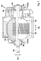
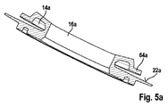
図1は、電気モータによって具体化された電気駆動装置の回転子ユニット46aを示す。電気モータは電気加熱ファンおよび/または空調ファンを駆動するために設けられる。電気モータはDCモータとして実装される。しかしながら、電気モータが、BLDCモータとして、または、当業者によって適切と思われる別のやり方で実装されることも考えられる。電気モータは、アーマチャ要素30a、整流子32a、第1の支持要素34a、第2の支持要素36a、および減衰ユニット10aを備える。電気モータの回転子ユニット46aはアーマチャ要素30aを備える。アーマチャ要素30aは鉄で実装される。アーマチャ要素30aは、互いに積み重ねられる鉄板で実装される。アーマチャ要素30aは、少なくとも1つの巻線48aに及ぶ(詳細に図示されない)溝を備える。アーマチャ要素30aは複数の巻線48aを備える。巻線48aは概略的に図示される整流子32aに接続される。巻線48aはアーマチャ要素30aの巻き取りヘッドにわたって延在する。アーマチャ要素30aは、アーマチャ要素30aの主拡張方向52aにおいて相対して配置される2つの巻き取りヘッドを備える。アーマチャ要素30aの主拡張方向52aは、回転子ユニット46aのアーマチャシャフト28aに平行に延在する。
FIG. 1 shows a
巻き取りヘッドの領域では、巻線48aは互いに交差するように配置される。巻線48aは、磁場が誘導される結果として、動作状態において電流が流れるように設けられる。誘導された磁場は、動作状態において、電気モータの(図示されない)固定子ユニットの磁場と共に作用する。回転子ユニット46aは、電気モータの回転子ユニット46aの出力移動を加熱ファンおよび/または空調ファンの駆動スピンドル上に伝達させるための(図示されない)出力歯車装置をさらに備える。
In the region of the winding head, the
電気モータはさらに、アーマチャシャフト28aの回転軸を中心に回転可能であるように回転子ユニット46aを支持する、第1の支持要素34aおよび第2の支持要素36aを備える。第1の支持要素34aおよび第2の支持要素36aは、電気モータの回転子ユニット46aの主拡張方向52aに見ると、アーマチャ要素30aの両側に配置される。第1の支持要素34aおよび第2の支持要素36aは、電気モータの回転子ユニット46aの主拡張方向52aに見ると、アーマチャ要素30aを取り囲む。第1の支持要素34aおよび第2の支持要素36aはアーマチャシャフト28aと直接接触する。第1の支持要素34aは、電気モータの回転子ユニット46aの主拡張方向52aに見ると、整流子32aから向きがそれている電気モータ回転子ユニット46aの側面上に配置される。第2の支持要素36aは、電気モータの回転子ユニット46aの主拡張方向52aに見ると、整流子32aの方へ面する電気モータ回転子ユニット46aの側面上に配置される。第1の支持要素34aおよび第2の支持要素36aは滑り軸受として具体化される。第1の支持要素34aおよび第2の支持要素36aはカップアンドボール(cup−and−ball)軸受によって具体化される。しかしながら、当業者によって適切と思われる、第1の支持要素34aおよび第2の支持要素36aの他の実装形態も考えられる。回転子ユニット46aのアーマチャ要素30aは、第1の支持要素34aおよび第2の支持要素36aに対して回転可能に支持される。回転子ユニット46aのアーマチャ要素30aは、電気モータの回転子ユニット46aの主拡張方向52aに見ると、第1の支持要素34aおよび第2の支持要素36aに対して縦方向の隙間を有する。その縦方向の隙間は、0.1mm〜0.4mmの間隔を有する。電気モータの動作状態において、縦方向のアーマチャ発振、ひいては電気モータの高作動ノイズレベルがアーマチャ要素30aの縦方向の隙間によって生じる場合がある。
The electric motor further includes a
電気モータの動作状態においてアーマチャ要素30aの縦方向のアーマチャ発振を減衰する目的のために、減衰ユニット10aが設けられる。減衰ユニット10aは、少なくとも1つの第1の支持要素34aと少なくとも1つのアーマチャ要素30aとの間で少なくとも部分的に、および/または、少なくとも1つの整流子32aと少なくとも1つの第2の支持要素36aとの間で少なくとも部分的にアーマチャシャフト28a上に配置される。減衰ユニット10aは少なくとも1つの軸受要素12aを備える。減衰ユニット10aは少なくとも2つの軸受要素12aを備える。減衰ユニット10aは、第1の軸受要素12aおよび第2の軸受要素12aを備える。第1の軸受要素12aおよび第2の軸受要素12aはそれぞれスラスト座金56aとして具体化される。軸受要素12aは円盤状に具体化される。しかしながら、軸受要素12aが少なくとも部分的に円盤片のように成形されるように具体化されることも考えられる。電気モータの回転子ユニット46aの主拡張方向52aに見ると、第1の軸受要素12aは、第1の支持要素34aとアーマチャ要素30aとの間に配置される。電気モータの回転子ユニット46aの主拡張方向52aに見ると、第2の軸受要素12aは、整流子32aと第2の支持要素36aとの間に配置される。
An
電気モータの動作状態において、縦方向のアーマチャ発振によってアーマチャ要素30aから支持要素34a、36a上へ伝達された軸力は、軸受要素12a上へ伝達され、主拡張方向52aに垂直に配置される軸受要素12aの表面を介して緩和される。軸受要素12aはプラスチック材料で実装される。しかしながら、軸受要素12aの、例えば、特に、当業者によって適切と思われる追加のまたは代替的な材料の他の実装形態も考えられる。図1に示される例示の実施形態において、減衰ユニット10aは電気モータの筐体内に配置される。しかしながら、減衰ユニットが電気モータの筐体外に少なくとも部分的に配置されることも考えられる。
In the operating state of the electric motor, the axial force transmitted from the
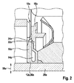
図2は、軸受要素12aのうちの1つの断面の断面図を示す。第1の軸受要素12aおよび第2の軸受要素12aは少なくともおおむね同一に具体化される。第1の軸受要素12aおよび第2の軸受要素12aは同一に具体化される。第1の軸受要素12aは、少なくとも1つの動作状態において電気モータの少なくとも1つの縦方向のアーマチャ発振を減衰するための少なくとも1つの空洞14aを備える。第2の軸受要素12aは、少なくとも1つの動作状態において電気モータの少なくとも1つの縦方向のアーマチャ発振を減衰するための少なくとも1つの空洞14aを備える。軸受要素12aはそれぞれ、少なくとも1つの動作状態において電気モータの少なくとも1つの縦方向のアーマチャ発振を減衰するための空洞14aを備える。組み立て状態の空洞14aは、対応して1流体クッションを形成し、この流体クッションは、動作状態において電気モータの縦方向のアーマチャ発振を減衰するために設けられる。組み立て状態の空洞14aは対応して1空気クッションを形成する。空洞14aは各軸受要素12aの減衰領域を実装する。
FIG. 2 shows a cross-sectional view of one of the
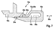
空洞14aは、少なくとも部分的に軸受要素12aの周方向20aに沿って対応して配置される。空洞14aは、軸受要素12aの周方向20aに沿って対応して周辺に配置される。空洞14aは対応してリング状に具体化される。軸受要素12aの接線方向に垂直に配置される平面では、空洞14aは、それぞれが三角形領域、矩形領域、および半円領域を備える2つの断面積をそれぞれ備える。半円領域、矩形領域および三角形領域は、内部から外部へ軸受要素12aの半径方向58aに見られる場合、それぞれが続いて配置される。しかしながら、軸受要素12aの接線方向に垂直に配置される平面における、例えば、多角形、滴形、円形、矩形、楕円形、または正方形の、空洞14aの断面積の、当業者によって適切と思われる他の実装形態も考えられる。空洞14aによって、対応する軸受要素12aの減衰特性は影響を受ける可能性があり、対応する軸受要素12aの弾性区域は実現可能である。
The
空洞14aの領域において、第1の射出成形要素16aは、半径方向58aに見ると、動作状態において曲がり梁としての役割を果たし、かつ、空洞の方へ弾性的に変形可能な区域を含む。第1の支持要素からまたは第2の支持要素から軸受要素上へ、縦方向のアーマチャ発振によって動作状態で作用する軸力によって、空洞14aの領域において第1の射出成形要素16aの弾性変形が生じるため減衰される。
In the region of the
さらに、空洞14aの内部に、停止要素50aが設けられることが考えられる。この停止要素50aは、動作状態で空洞14aの領域において軸受要素12aの変形の範囲を定めるために設けられる。停止要素50aは図7において破線で示される。停止要素50aはプラスチック材料で作られる。停止要素50aは空洞14aに沿って周辺に延在するように具体化されてよい。しかしながら、周方向20aに見ると、空洞14aに沿って規則的に分布されるように配置される複数の停止要素50a、例えば3つの停止要素50aが設けられることも考えられる。停止要素50aは、軸受要素12aの第1の射出成形要素16aに固定して接続される。停止要素50aは、一部品実装形態において、軸受要素12aの第1の射出成形要素16aによって具体化される。しかしながら、停止要素50aが、軸受要素12aの第1の射出成形要素16aに接着剤で付けられるか、当業者によって適切と思われる別のやり方で軸受要素12aの第1の射出成形要素16aに接続されることも考えられる。
Furthermore, it is conceivable that a
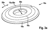
減衰ユニット10aの第1の軸受要素12aおよび第2の軸受要素12aはそれぞれ、第1の射出成形要素16aおよび第2の射出成形要素18aを備える(図3aおよび図3b)。第1の射出成形要素16aおよび第2の射出成形要素18aは、2段階射出成形手順において連続して形成される。第1の射出成形要素16aおよび第2の射出成形要素18aは少なくとも部分的に互いに固定して接続される。第1の射出成形要素16aおよび第2の射出成形要素18aはそれぞれ、互いに固定して接続される。第1の射出成形要素16aおよび第2の射出成形要素18aは少なくとも部分的に一部品実装形態において具体化される。第1の射出成形要素16aおよび第2の射出成形要素18aはそれぞれ、一部品実装形態において具体化される。第1の射出成形要素16aは射出成形手順の第1のステップ60において形成される。次いで、第2の射出成形要素18aは射出成形手順の第2のステップ62において形成され、第1の射出成形要素16a上に射出される。しかしながら、第2の射出成形要素18aが射出成形手順の第2のステップ62において別個に形成され、次いで、第1の射出成形要素16aに接続されることも考えられる。
The
第1の軸受要素12aおよび第2の軸受要素12aはそれぞれ、第1の射出成形要素16aと第2の射出成形要素18aとの間に超音波機械加工接触区域22a、24aを含む(図7)。第1の射出成形要素16aは接触区域22aを備える。第2の射出成形要素18aは接触区域24aを備える。第1の射出成形要素16aと第2の射出成形要素18aとの間の超音波機械加工区域22a、24aにおいて、第1の軸受要素12aおよび第2の軸受要素12aはそれぞれ、第1の射出成形要素16aと第2の射出成形要素18aとの間に高い付着性を有するため、減衰ユニット10aの動作状態において軸受要素12aの第1の射出成形要素16aと第2の射出成形要素18aとの間の物質間結合が解除されないようにすることができる。
The
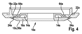
第1の射出成形要素16aおよび第2の射出成形要素18aは少なくとも部分的に同じ材料で具体化される。第1の射出成形要素16aおよび第2の射出成形要素18aはそれぞれ完全に同じ材料で具体化される。第1の射出成形要素16aおよび第2の射出成形要素18aはプラスチック材料で作られる。しかしながら、当業者によって適切と思われる他の材料も考えられる。第1の軸受要素12aの空洞14aおよび第2の軸受要素12aの空洞14aはそれぞれ、少なくともおおむね、第1の射出成形要素16aまたは第2の射出成形要素18aに配置される(図4)。第1の軸受要素12aの空洞14aは、第1の射出成形要素16aに配置され、かつ、第1の射出成形要素16aに完全に囲まれる。第2の軸受要素12aの空洞14aは、第1の射出成形要素16aに配置され、かつ、第1の射出成形要素16aに完全に囲まれる。しかしながら、空洞14aが第2の射出成形要素18aに配置され、かつ、第2の射出成形要素18aに囲まれることも考えられる。組み立て状態で、第1の軸受要素12aの空洞14a、および第2の軸受要素12aの空洞14aはそれぞれ、少なくともおおむね気密に具体化される。組み立て状態で、第1の軸受要素12aの空洞14aおよび第2の軸受要素12aの空洞14aはそれぞれ気密に具体化される。
The first
図11は減衰ユニット10aを製作するための方法のフロー図を示す。減衰ユニット10aを製作するための方法の方法ステップ38、40では、第1の軸受要素12aおよび第2の軸受要素12aは、2段階射出成形手順において少なくとも部分的に形成される。第1の軸受要素12aおよび第2の軸受要素12aは、2段階射出成形手順で減衰ユニット10aを製作するための方法の方法ステップ38、40において少なくともほぼ完全に形成される。第1の射出成形要素16aが、方法の方法ステップ38に対応する、射出成形手順の第1のステップ60において形成された時、第1の射出成形要素16aに取り入れられた空洞14aは開放して実装される。第1の射出成形要素16aは、組み立て状態で第1の射出成形要素16aの接触区域22aに直接接触させるために設けられることで、空洞14aを閉鎖する突出区域64aを備える。
FIG. 11 shows a flow diagram of a method for fabricating the
非組み立て状態では、第1の射出成形要素16aの突出区域64aは、第1の射出成形要素16aの接触区域22aから間隔をあけて配置される。減衰ユニット10aを製作するための方法のさらなる方法ステップ44では、第1の軸受要素12aもしくは第2の軸受要素22aの第1の射出成形要素16aまたは第2の射出成形要素18aにおいて配置される空洞14aは、少なくともおおむね閉鎖される。減衰ユニット10aを製作するための方法のさらなる方法ステップ44では、第1の射出成形要素16aに取り入れられた空洞14aは閉鎖される。空洞14aは、さらなる方法ステップ44において、突出区域64aを第1の射出成形要素16aの接触区域22aに押し付けることによって閉鎖される。次いで、方法の方法ステップ40に対応する、射出成形手順の第2のステップ62では、第2の射出成形要素18aは第1の射出成形要素16a上に射出される。この結果、第1の射出成形要素16aの突出区域64aを、空洞14aの閉鎖状態において第1の射出成形要素16aの接触区域22aに対して定着させる。
In the unassembled state, the protruding
減衰ユニット10aを製作するための方法のさらなる方法ステップ42では、第1の軸受要素12aおよび第2の軸受要素12aはそれぞれ、超音波溶接手順によって少なくとも部分的に処理される。減衰ユニット10aを製作するための方法のさらなる方法ステップ42では、第1の軸受要素12aおよび第2の軸受要素12aはそれぞれ、第1の射出成形要素16aと第2の射出成形要素18aとの間で接触区域22a、24aにおいて超音波溶接手順によって処理される。しかしながら、第1の射出成形要素16aと第2の射出成形要素18aとの間の接着力を改良するための、当業者にとって適切と思われる他の手順も考えられる。第1の射出成形要素16aの接触区域22aと第2の射出成形要素18aの接触区域24aとの物質間結合はこのように改良されてよい。
In a
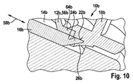
図8〜図10において、本発明のさらなる例示の実施形態が示される。以下の説明および図面は、例示の実施形態間の相違点におおむね限定され、この場合、同じ名称を有する構造部品、特に、同じ参照符号を有する構造部品に関して、主として、他の例示の実施形態、特に、図1〜図7の図面および/または説明に言及する場合もある。例示の実施形態を区別する目的のために、文字「a」は、図1〜図7の例示の実施形態の参照符号に追加される。図8〜図10の例示の実施形態では、文字「a」は文字「b」によって置き換えられている。 8-10, a further exemplary embodiment of the present invention is shown. The following description and drawings are largely limited to the differences between the exemplary embodiments, in which case the other exemplary embodiments are mainly described with respect to structural parts having the same name, in particular, structural parts having the same reference numerals. In particular, the drawings and / or descriptions of FIGS. For purposes of distinguishing the exemplary embodiments, the letter “a” is added to the reference numbers of the exemplary embodiments of FIGS. In the exemplary embodiment of FIGS. 8-10, the letter “a” is replaced by the letter “b”.
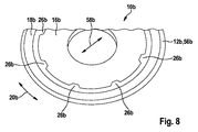
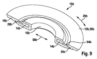
図8〜図10は、代替的に実装された減衰ユニット10aの軸受要素12bを示す。軸受要素12bは主に、既述の軸受要素12aに対応する。代替的に実装された減衰ユニット10bは2つの軸受要素12bを備える。軸受要素12bは少なくともおおむね同一に具体化される。軸受要素12bは同一に具体化される。代替的に実装された減衰ユニット10bは、既述の方法によって製作される。軸受要素12bは第1の射出成形要素16bおよび第2の射出成形要素18bを備える。第1の射出成形要素16bおよび第2の射出成形要素18bは、2段階射出成形手順において連続して形成される。第1の射出成形要素16bおよび第2の射出成形要素18bは少なくとも部分的に互いに固定して接続される。第1の射出成形要素16bおよび第2の射出成形要素18bはそれぞれ、互いに固定して接続される。第1の射出成形要素16bおよび第2の射出成形要素18bは少なくとも部分的に一部品実装形態において具体化される。第1の射出成形要素16bおよび第2の射出成形要素18bはそれぞれ、一部品実装形態において具体化される。第1の射出成形要素16bは射出成形手順において第2の射出成形要素18b上に射出される。第1の射出成形要素16bおよび第2の射出成形要素18bは物質間結合によって互いに接続される。
8 to 10 show the
軸受要素12bは、少なくとも部分的に、少なくとも1つの第1の射出成形要素16bと少なくとも1つの第2の射出成形要素18bとの間の形状嵌め連結のために設けられる少なくとも1つの連動要素26bを備える。軸受要素12bは少なくとも2つの連動要素26bを備える。軸受要素12bは、第1の射出成形要素16bと第2の射出成形要素18bとの間のさらなる形状嵌め連結のために設けられる複数の連動要素26bを備える。連動要素26bは、軸受要素12bの周方向20bに規則的に分布するように配置される。軸受要素12bは周方向20bに規則的に分布される8つの連動要素26bを備える。連動要素26bの少なくとも1つは、一部品実装形態において少なくとも部分的に、第1の射出成形要素16bまたは第2の射出成形要素18bによって具体化される。連動要素26bは一部品実装形態において第2の射出成形要素18bによって具体化される。連動要素26bはそれぞれ、第2の射出成形要素18bの縁から内方へ半径方向58bに延在する台形状の輪郭を備える。該輪郭は軸受要素12bの半径方向58bに見ると内縁である。しかしながら、例えば、特に半円、三角形、楕円形、および/または矩形の輪郭を有する、当業者によって適切と思われる連動要素の他の実装形態も考えられる。組み立て状態では、第2の射出成形要素18bの連動要素26bは、軸受要素12bの周方向20bに平行に配置される平面において第1の射出成形要素16b上に射出成形され、それらは、物質間結合によって第1の射出成形要素16bを定着させる。組み立て状態では、第2の射出成形要素18bの連動要素26bは、軸受要素12bの周方向20bに平行に配置される平面において第1の射出成形要素16b上で係合し、第1の射出成形要素16bを形状嵌めするように定着させる。
The
Claims (15)
前記少なくとも1つの空洞(14)は前記少なくとも1つの第1の射出成形要素(16)または前記少なくとも1つの第2の射出成形要素(18)において少なくともおおむね配置されることを特徴とする、減衰ユニット。 Provided for attenuating at least one longitudinal armature oscillation of the electric motor in at least one operating state, and at least for attenuating the at least one longitudinal armature oscillation of the electric motor in at least one operating state. A damping unit comprising at least one bearing element (12) comprising one cavity (14) and comprising at least one first injection molding element (16) and at least one second injection molding element (18). There,
Damping unit, characterized in that said at least one cavity (14) is at least generally arranged in said at least one first injection molding element (16) or in said at least one second injection molding element (18) .
少なくとも1つのアーマチャ要素(30)と、
少なくとも1つの整流子(32)と、
少なくとも1つの第1の支持要素(34)および少なくとも1つの第2の支持要素(36)と、
前記少なくとも1つの第1の支持要素(34)と前記少なくとも1つのアーマチャ要素(30)との間で少なくとも部分的に、および/または、前記少なくとも1つの整流子(32)と前記少なくとも1つの第2の支持要素(36)との間で少なくとも部分的に前記アーマチャシャフト(28)上に配置される、請求項1〜11のうちいずれか一項に記載の減衰ユニット(10)と、を有する、電気モータ。 At least one armature shaft (28);
At least one armature element (30);
At least one commutator (32);
At least one first support element (34) and at least one second support element (36);
At least partially between the at least one first support element (34) and the at least one armature element (30) and / or the at least one commutator (32) and the at least one first element. 12. Damping unit (10) according to any one of the preceding claims, arranged at least partly on the armature shaft (28) between two support elements (36). , Electric motor.
前記減衰ユニット(10)の少なくとも1つの軸受要素(12)が少なくとも2段階射出成形手順において少なくとも部分的に形成される少なくとも1つの方法ステップ(38、40)を特徴とする、方法。 A method for producing a damping unit (10) according to any one of the preceding claims,
A method characterized in that at least one bearing element (12) of said damping unit (10) is at least partly formed in at least a two-stage injection molding procedure at least one method step (38, 40).
Applications Claiming Priority (3)
| Application Number | Priority Date | Filing Date | Title |
|---|---|---|---|
| DE102014102134.7A DE102014102134A1 (en) | 2014-02-19 | 2014-02-19 | damping unit |
| DE102014102134.7 | 2014-02-19 | ||
| PCT/EP2014/078535 WO2015124238A1 (en) | 2014-02-19 | 2014-12-18 | Damping unit |
Publications (2)
| Publication Number | Publication Date |
|---|---|
| JP2017517233A true JP2017517233A (en) | 2017-06-22 |
| JP2017517233A5 JP2017517233A5 (en) | 2018-05-17 |
Family
ID=52146490
Family Applications (1)
| Application Number | Title | Priority Date | Filing Date |
|---|---|---|---|
| JP2016548347A Ceased JP2017517233A (en) | 2014-02-19 | 2014-12-18 | Attenuation unit |
Country Status (8)
| Country | Link |
|---|---|
| US (1) | US20170018990A1 (en) |
| EP (1) | EP3108573B1 (en) |
| JP (1) | JP2017517233A (en) |
| KR (1) | KR20160138010A (en) |
| CN (1) | CN106030999B (en) |
| BR (1) | BR112016018677B1 (en) |
| DE (1) | DE102014102134A1 (en) |
| WO (1) | WO2015124238A1 (en) |
Families Citing this family (2)
| Publication number | Priority date | Publication date | Assignee | Title |
|---|---|---|---|---|
| EP3455504B1 (en) * | 2016-08-26 | 2023-10-04 | ebm-papst St. Georgen GmbH & Co. KG | Device, in particular fan device, and method for damping a device, in particular a fan device |
| CN107612184B (en) * | 2017-10-19 | 2024-02-20 | 广州市瑞宝电器有限公司 | Integrated motor end cover and finish machining method thereof |
Citations (4)
| Publication number | Priority date | Publication date | Assignee | Title |
|---|---|---|---|---|
| JPS5226106U (en) * | 1975-08-14 | 1977-02-23 | ||
| JPS53149805U (en) * | 1977-04-30 | 1978-11-25 | ||
| US5683184A (en) * | 1994-08-24 | 1997-11-04 | Siemens Aktiengesellschaft | Thrust and cover washer, mounted on a rotor shaft, for a bearing of the rotor shaft |
| WO2012156132A2 (en) * | 2011-05-18 | 2012-11-22 | Robert Bosch Gmbh | Thrust washer for an electric machine |
Family Cites Families (6)
| Publication number | Priority date | Publication date | Assignee | Title |
|---|---|---|---|---|
| US3573510A (en) * | 1969-06-09 | 1971-04-06 | Gen Electric | Cushion thrust washer |
| DE3145601C3 (en) * | 1981-11-17 | 1992-08-06 | Mulfingen Elektrobau Ebm | Thrust washer |
| US5945756A (en) * | 1997-10-07 | 1999-08-31 | Siemens Canada Limited | Ultra quiet electric motor for automotive applications |
| US6376952B1 (en) * | 1999-07-14 | 2002-04-23 | E. I. Du Pont De Nemours And Company | Bearing system for a rotating shaft |
| DE102008062432A1 (en) * | 2008-12-17 | 2010-07-15 | Brose Fahrzeugteile GmbH & Co. Kommanditgesellschaft, Würzburg | Electromotive drive, in particular fan drive |
| DE102011076081A1 (en) * | 2011-05-18 | 2012-11-22 | Robert Bosch Gmbh | Thrust washer for an electric machine |
-
2014
- 2014-02-19 DE DE102014102134.7A patent/DE102014102134A1/en not_active Withdrawn
- 2014-12-18 KR KR1020167025529A patent/KR20160138010A/en not_active Application Discontinuation
- 2014-12-18 JP JP2016548347A patent/JP2017517233A/en not_active Ceased
- 2014-12-18 EP EP14818974.9A patent/EP3108573B1/en active Active
- 2014-12-18 US US15/119,159 patent/US20170018990A1/en not_active Abandoned
- 2014-12-18 WO PCT/EP2014/078535 patent/WO2015124238A1/en active Application Filing
- 2014-12-18 CN CN201480075806.5A patent/CN106030999B/en active Active
- 2014-12-18 BR BR112016018677-0A patent/BR112016018677B1/en active IP Right Grant
Patent Citations (4)
| Publication number | Priority date | Publication date | Assignee | Title |
|---|---|---|---|---|
| JPS5226106U (en) * | 1975-08-14 | 1977-02-23 | ||
| JPS53149805U (en) * | 1977-04-30 | 1978-11-25 | ||
| US5683184A (en) * | 1994-08-24 | 1997-11-04 | Siemens Aktiengesellschaft | Thrust and cover washer, mounted on a rotor shaft, for a bearing of the rotor shaft |
| WO2012156132A2 (en) * | 2011-05-18 | 2012-11-22 | Robert Bosch Gmbh | Thrust washer for an electric machine |
Also Published As
| Publication number | Publication date |
|---|---|
| US20170018990A1 (en) | 2017-01-19 |
| DE102014102134A1 (en) | 2015-08-20 |
| KR20160138010A (en) | 2016-12-02 |
| BR112016018677A2 (en) | 2017-08-08 |
| CN106030999B (en) | 2020-03-10 |
| BR112016018677B1 (en) | 2022-01-04 |
| CN106030999A (en) | 2016-10-12 |
| WO2015124238A1 (en) | 2015-08-27 |
| EP3108573B1 (en) | 2020-02-26 |
| EP3108573A1 (en) | 2016-12-28 |
Similar Documents
| Publication | Publication Date | Title |
|---|---|---|
| KR102054681B1 (en) | Motor assembly, method of manufacturing the same and a cleaner having the same | |
| JP6689318B2 (en) | Electric machine | |
| CN108206600B (en) | Motor and handheld product with motor | |
| JP5669840B2 (en) | Device for acoustically decoupling a stator in an electric motor | |
| US20070267924A1 (en) | Vibration damping rotor assembly for rotating machinery | |
| JP2017517233A (en) | Attenuation unit | |
| JP2017517233A5 (en) | ||
| CN106992616A (en) | Vibration damping rotor and motor | |
| KR20010014126A (en) | Fan | |
| CN105201923A (en) | Draught fan absorber and draught fan | |
| JP6597327B2 (en) | Rotating electric machine | |
| KR101758033B1 (en) | Rotor disc and rotor for a vacuum pump | |
| KR101239556B1 (en) | A Permanent-magnet rotor for an external-rotor electric motor particularly for washing machines and similar household appliances and relevant manufacturing method | |
| JP6265879B2 (en) | Damper and stepping motor using the same | |
| JP2007014200A (en) | Production method of plastic magnet rotor, plastic magnet rotor, and air conditioner | |
| KR101002959B1 (en) | Stator component of plastic packaged brushless-motor | |
| JP4348606B2 (en) | Axial gap type electric motor | |
| JP2020153275A (en) | Centrifugal fan | |
| JP2015212555A (en) | Vibration control structure of rotor | |
| JPH0847203A (en) | Rotor of motor | |
| JP7025560B2 (en) | Electric motor | |
| JP2000110780A (en) | Impeller of fan | |
| JP2007320257A (en) | Power tool and fan for power tool | |
| KR101939391B1 (en) | Damper pulley of heterogeneous material | |
| JPS6235973Y2 (en) |
Legal Events
| Date | Code | Title | Description |
|---|---|---|---|
| A521 | Request for written amendment filed |
Free format text: JAPANESE INTERMEDIATE CODE: A523 Effective date: 20170623 |
|
| A977 | Report on retrieval |
Free format text: JAPANESE INTERMEDIATE CODE: A971007 Effective date: 20171221 |
|
| A131 | Notification of reasons for refusal |
Free format text: JAPANESE INTERMEDIATE CODE: A131 Effective date: 20180109 |
|
| A524 | Written submission of copy of amendment under article 19 pct |
Free format text: JAPANESE INTERMEDIATE CODE: A524 Effective date: 20180326 |
|
| A01 | Written decision to grant a patent or to grant a registration (utility model) |
Free format text: JAPANESE INTERMEDIATE CODE: A01 Effective date: 20180821 |
|
| A045 | Written measure of dismissal of application [lapsed due to lack of payment] |
Free format text: JAPANESE INTERMEDIATE CODE: A045 Effective date: 20181218 |