JP2017517096A - Cable arrangement - Google Patents
Cable arrangement Download PDFInfo
- Publication number
- JP2017517096A JP2017517096A JP2016562557A JP2016562557A JP2017517096A JP 2017517096 A JP2017517096 A JP 2017517096A JP 2016562557 A JP2016562557 A JP 2016562557A JP 2016562557 A JP2016562557 A JP 2016562557A JP 2017517096 A JP2017517096 A JP 2017517096A
- Authority
- JP
- Japan
- Prior art keywords
- cable
- cables
- arrangement
- spacer
- twisted
- Prior art date
- Legal status (The legal status is an assumption and is not a legal conclusion. Google has not performed a legal analysis and makes no representation as to the accuracy of the status listed.)
- Pending
Links
Images
Classifications
-
- H—ELECTRICITY
- H02—GENERATION; CONVERSION OR DISTRIBUTION OF ELECTRIC POWER
- H02G—INSTALLATION OF ELECTRIC CABLES OR LINES, OR OF COMBINED OPTICAL AND ELECTRIC CABLES OR LINES
- H02G3/00—Installations of electric cables or lines or protective tubing therefor in or on buildings, equivalent structures or vehicles
- H02G3/02—Details
- H02G3/04—Protective tubing or conduits, e.g. cable ladders or cable troughs
- H02G3/0462—Tubings, i.e. having a closed section
- H02G3/0481—Tubings, i.e. having a closed section with a circular cross-section
-
- H—ELECTRICITY
- H01—ELECTRIC ELEMENTS
- H01B—CABLES; CONDUCTORS; INSULATORS; SELECTION OF MATERIALS FOR THEIR CONDUCTIVE, INSULATING OR DIELECTRIC PROPERTIES
- H01B11/00—Communication cables or conductors
- H01B11/02—Cables with twisted pairs or quads
- H01B11/04—Cables with twisted pairs or quads with pairs or quads mutually positioned to reduce cross-talk
-
- H—ELECTRICITY
- H01—ELECTRIC ELEMENTS
- H01B—CABLES; CONDUCTORS; INSULATORS; SELECTION OF MATERIALS FOR THEIR CONDUCTIVE, INSULATING OR DIELECTRIC PROPERTIES
- H01B11/00—Communication cables or conductors
- H01B11/005—Quad constructions
-
- H—ELECTRICITY
- H01—ELECTRIC ELEMENTS
- H01B—CABLES; CONDUCTORS; INSULATORS; SELECTION OF MATERIALS FOR THEIR CONDUCTIVE, INSULATING OR DIELECTRIC PROPERTIES
- H01B11/00—Communication cables or conductors
- H01B11/02—Cables with twisted pairs or quads
- H01B11/06—Cables with twisted pairs or quads with means for reducing effects of electromagnetic or electrostatic disturbances, e.g. screens
-
- H—ELECTRICITY
- H01—ELECTRIC ELEMENTS
- H01B—CABLES; CONDUCTORS; INSULATORS; SELECTION OF MATERIALS FOR THEIR CONDUCTIVE, INSULATING OR DIELECTRIC PROPERTIES
- H01B7/00—Insulated conductors or cables characterised by their form
- H01B7/0045—Cable-harnesses
Abstract
本発明は、隣接して延在する少なくとも2本のケーブル(10,20)の配列(100)に関し、第1ケーブル(10)と第2ケーブル(20)とが、撚り合わせた2本以上の導体(32)を有する少なくとも1本の撚り線群(11,21)を各々有するとともに、前記撚り線群を包囲する共通のケーブルシース(15,25)を各々有し、前記2本のケーブル(10,20)の前記撚り線群(11,21)間の最小間隔(A)を拡大させるために、前記ケーブルシース(15,25)のうち少なくとも一方の外側にスペーサ(30)が配置される。The present invention relates to an arrangement (100) of at least two cables (10, 20) extending adjacent to each other, wherein the first cable (10) and the second cable (20) are twisted together. Each of the two cables (11) includes at least one stranded wire group (11, 21) having a conductor (32), and each has a common cable sheath (15, 25) surrounding the stranded wire group. In order to enlarge the minimum distance (A) between the twisted wire groups (11, 21) of 10, 20), a spacer (30) is arranged outside at least one of the cable sheaths (15, 25). .
Description
本発明は、隣接して延在する少なくとも2本のケーブルの配列に関し、第1ケーブルと第2ケーブルとが、撚り合わせた2本以上の導体を有する少なくとも1本の撚り線群を各々有するとともに、撚り線群を包囲する共通のケーブルシースを各々有する。 The present invention relates to an arrangement of at least two cables extending adjacent to each other, and each of the first cable and the second cable has at least one twisted wire group having two or more conductors twisted together. , Each having a common cable sheath surrounding the strand group.
縒り合わせ(twisting)又は撚り合わせ(stranding)は、一般に数本の素線(wire)又はケーブルの導体を、互いの周りに螺旋状に撚り合わせることを意味すると理解される。例えば、既知のツイストペアケーブルは、互いの周りに撚り合わせた2本の導体を含む少なくとも1本の撚り線群を有する。それにより、個々の導体は、ケーブルの長手方向に位置変化する。加えて、縒り合わせ又は撚り合わせた対は、外部の交流電磁場及び静電干渉に対して、より良い保護を提供する。 Twisting or stranding is generally understood to mean twisting several wire or cable conductors around each other in a spiral. For example, known twisted pair cables have at least one strand group that includes two conductors twisted around each other. Thereby, the position of the individual conductors changes in the longitudinal direction of the cable. In addition, twisted or twisted pairs provide better protection against external AC electromagnetic fields and electrostatic interference.
プラスチック等の誘電体で通常形成される共通のケーブルシースは、個別の絶縁を各々施された導体(素線)を包囲する。 A common cable sheath, usually formed of a dielectric material such as plastic, surrounds each individual insulated conductor (element wire).
ケーブル内で互いに隣接して伸びる数本の導体対の間のクロストークも、撚り合わせによって有効に低減させることができる。さらに、ケーブルの個々の撚り線群の異なる撚り長さ及び/又は回転方向は選択され得る。第1導体対からの外部信号は、誘導的又は容量的に、隣接する第2導体対に結合させることができる。 Crosstalk between several pairs of conductors extending adjacent to each other in the cable can also be effectively reduced by twisting. Furthermore, different twist lengths and / or directions of rotation of the individual strands of the cable can be selected. The external signal from the first conductor pair can be inductively or capacitively coupled to the adjacent second conductor pair.
ケーブル間のそのような望ましくないクロストーク(エイリアンクロストーク)は、ディファレンシャル信号を伝送するための少なくとも一対の導体対を各々有する数本のケーブルが互いに隣接して配置されている場合にも発生する可能性がある。このクロストークを低減するために、個々のケーブルは、通常はシールドを有する。又は、同軸ケーブルが用いられる。 Such undesirable crosstalk between cables (alien crosstalk) also occurs when several cables, each having at least one pair of conductors for transmitting differential signals, are arranged adjacent to each other. there is a possibility. In order to reduce this crosstalk, individual cables usually have shields. Alternatively, a coaxial cable is used.
特許文献1は、1本のケーブルに数本の撚り線群を配置し、それにより撚り線群が互いに撚り合わされるということを記載している。個々の撚り線の撚り長さは多様であってよい。しかしながら、そのようなケーブルの製造は、特に複雑である。また、互いに隣接して配置された数本のそのようなケーブル間でエイリアンクロストークが発生する可能性がある。 Patent Document 1 describes that several twisted wire groups are arranged in one cable, and thereby the twisted wire groups are twisted together. The twist length of the individual strands may vary. However, the manufacture of such cables is particularly complex. Also, alien crosstalk can occur between several such cables placed adjacent to each other.
特許文献2も、撚り線群の撚り長さが正弦波状に変化する2本の撚り線群の撚り合わせについて記載している。このケーブルも、製造が複雑である。この場合も、互いに隣接して配置された数本のそのようなケーブル間でエイリアンクロストークが発生する可能性がある。撚り長さは、撚り線群が辿る螺旋のピッチ又は巻線距離を意味すると理解される。言い換えると、撚り長さは、ケーブルの長手方向(z方向)における完全に一回転する間に、撚り線群の撚り線のうちの1本が撚れる距離である。 Patent Document 2 also describes the twisting of two twisted wire groups in which the twist length of the twisted wire group changes in a sine wave shape. This cable is also complicated to manufacture. Again, alien crosstalk can occur between several such cables placed adjacent to each other. The twist length is understood to mean the helical pitch or winding distance followed by the strands. In other words, the twist length is a distance that one of the twisted wires of the twisted wire group can be twisted during one complete rotation in the longitudinal direction (z direction) of the cable.
上記の問題を考慮して、本発明の目的は、各々がディファレンシャル信号の伝送に適した、互いに隣接して伸びる数本のケーブルの配列を提供することであり、この配列は製造が容易であり、同時に、個々のケーブルの導体対の間のクロストークが確実に防止、又は少なくとも最小限に抑えられる。 In view of the above problems, an object of the present invention is to provide an array of several cables extending adjacent to each other, each suitable for the transmission of a differential signal, which is easy to manufacture. At the same time, crosstalk between the conductor pairs of the individual cables is reliably prevented or at least minimized.
それにより、個々のケーブルのシールドは、一方でシールドが高価であり、また他方でシールドがケーブルの重量及び可撓性に悪影響を与える可能性があることから、好ましくは省略されるべきである。 Thereby, individual cable shields should preferably be omitted because the shields are expensive on the one hand and the shields on the other hand can adversely affect the weight and flexibility of the cable.
この課題は、本発明による請求項1に記載のケーブル配列によって解決される。本発明の有利なさらなる展開は、従属請求項に記載される。 This problem is solved by the cable arrangement according to claim 1 according to the present invention. Advantageous further developments of the invention are described in the dependent claims.
本発明に係るケーブル配列において、ケーブルシースのうち少なくとも1つは、2本のケーブルの撚り線群間の(最小)間隔を拡大させるために、ケーブルシースの外側に配置されたスペーサを有する。 In the cable arrangement according to the invention, at least one of the cable sheaths has a spacer arranged on the outside of the cable sheath in order to increase the (minimum) spacing between the twisted wire groups of the two cables.
この配列の個々のケーブルは、外側横境界面が少なくとも部分的に互いに接触した状態で隣接して配置されることができ、それにより、この場合、ケーブルシースの外面から始まる2本の撚り線群間の(可能な限り最小の)間隔は、スペーサによって、少なくともスペーサの半径方向厚さに対応する寸法だけ拡大する。それにより、スペーサの半径方向厚さは、個々のケーブルの撚り線群間のエイリアンクロストークが撚り線群間の最小間隔の拡大又は対策により予め定めた望ましい範囲に減衰されるように、伝送される信号強度、ケーブルシース径、撚り線群当たりの撚り導体の本数、ケーブル配列内のケーブルの本数ならびにケーブルの互いに対する配置(面内または3次元束の形式)等のパラメータに依存して設計されることができる。 The individual cables of this arrangement can be arranged adjacent with the outer lateral interface at least partly in contact with each other, whereby in this case two strands starting from the outer surface of the cable sheath The spacing (minimum possible) between is increased by the spacer by a dimension corresponding at least to the radial thickness of the spacer. Thereby, the radial thickness of the spacer is transmitted so that the alien crosstalk between the individual cable strands is attenuated to a predetermined desired range by increasing the minimum spacing between the strands or by countermeasures. Designed depending on parameters such as signal strength, cable sheath diameter, number of stranded conductors per group of stranded wires, number of cables in the cable array, and arrangement of cables relative to each other (in-plane or 3D bundle format) Can be.
本発明によれば、スペーサは、ケーブルシースの各々の外側に配置される。言い換えれば、配列における個々のケーブルの各々は、ケーブルシースの外側に取り付けられ得る少なくとも1つのスペーサを有する。この場合、2本の撚り線群の間隔は、スペーサによって、少なくともスペーサの半径方向厚さの二倍に相当する寸法、又は、2つのスペーサの半径方向厚さを合計した分だけ増加する。個々のケーブルのレイアウトに拘らず、これは撚り線群が所定の最小間隔Aよりも互いに近く接近することを防止することができる。 According to the present invention, the spacer is disposed outside each of the cable sheaths. In other words, each individual cable in the array has at least one spacer that can be attached to the outside of the cable sheath. In this case, the distance between the two twisted wire groups is increased by the spacer by a dimension corresponding to at least twice the radial thickness of the spacer or by the sum of the radial thicknesses of the two spacers. Regardless of the layout of the individual cables, this can prevent the strands from being closer together than the predetermined minimum spacing A.
本発明は、隣接する撚り線群間のクロストークが、撚り線群の間隔の拡大に伴って減少するという知見に基づいている。そのため、密接して伸びる撚り線群の間では、かなりの望ましくないエイリアンクロストークが発生する。しかし、この問題は、例えばケーブルの個々の撚り線群間の撚り長さを変えるといった既知の方策では、不十分な程度にしか改善できない。従来型のケーブルを配置するにあたり、ケーブル間の特定の最小間隔が維持されることを保証することも考えられる。しかしながら、そのような仕様を満たすことはケーブル敷設業者にとっては労力と時間とがかかる。望ましくないエイリアンクロストークは、多数のケーブルが互いに並列に伸びる場合、各ケーブルが非常に接近した数本の隣接するケーブルを有するため、この場合、特に大きくなり得る。本発明により、これらの問題は、ケーブルの外側に取り付けられたスペーサによって解決されることができるが、ケーブルが束状の配列である場合でさえ、スペーサが隣接する撚り線群間の特定の最小間隔を保証するからである。 The present invention is based on the finding that crosstalk between adjacent twisted wire groups decreases as the spacing between the twisted wire groups increases. As a result, considerable undesirable alien crosstalk occurs between closely extending strands. However, this problem can only be remedied to an inadequate extent by known measures, for example by changing the twist length between individual strands of the cable. In placing conventional cables, it is also conceivable to ensure that a certain minimum spacing between the cables is maintained. However, meeting such specifications is labor intensive and time consuming for cable installers. Undesirable alien crosstalk can be particularly large in this case when multiple cables extend in parallel with each other, since each cable has several adjacent cables in close proximity. With the present invention, these problems can be solved by spacers attached to the outside of the cable, but even if the cable is in a bundled arrangement, the spacer is a specific minimum between adjacent strands. This is because the interval is guaranteed.
本発明の好ましい1つの実施形態では、スペーサは、ケーブルシースを同軸に包囲する、好ましくは円形又は楕円形の外側輪郭を有するスリーブの形状に設計されている。スリーブの断面が円形である場合、そのようなスリーブに包囲された数本のケーブルの各々は、特に高密度のケーブルパッケージの形態で束状の形式で敷設されることができ、それにより個々のスリーブを互いに隣接して配置することができる。 In one preferred embodiment of the invention, the spacer is designed in the form of a sleeve having an outer contour, preferably circular or elliptical, that coaxially surrounds the cable sheath. If the cross-section of the sleeve is circular, each of the several cables enclosed in such a sleeve can be laid in a bundled form, especially in the form of a high-density cable package, whereby individual cables The sleeves can be placed adjacent to each other.
本発明の第1の代替形態では、ケーブルの外側又は各ケーブル上に、ケーブルの長手方向に例えば10cm未満の短い寸法のみを各々有する、ケーブルの長手方向に離間した数本のスリーブが配設される。しかしながら、本発明の特に好ましい代替形態では、スリーブは、全域にわたり、ケーブルの撚り線群が近づき過ぎることがないように、より長い範囲で、例えば1m超、特に3m以上にわたって長手方向に延在し、また、ケーブルの残りの部分と同様に可撓性である。それにより、ケーブル間のエイリアンクロストークがケーブルの全長にわたり確実に抑制されるように、スリーブがケーブルの全長の30%超、好ましくは50%超、特に好ましくは75%超、特にケーブルの全長にわたり延在すると実用的であることが実証された。 In a first alternative of the invention, several sleeves spaced in the longitudinal direction of the cable, each having only a short dimension, for example less than 10 cm in the longitudinal direction of the cable, are arranged on the outside or on each cable. The However, in a particularly preferred alternative of the invention, the sleeve extends longitudinally over a longer range, for example more than 1 m, in particular more than 3 m, so that the cable strands do not get too close over the entire area. Also, it is flexible like the rest of the cable. This ensures that the alien crosstalk between the cables is suppressed over the entire length of the cable, so that the sleeve is more than 30% of the total length of the cable, preferably more than 50%, particularly preferably more than 75%, especially over the entire length of the cable. Prolonged and proved practical.
ケーブルシース上に配置された付加的なケーブルシースの形態のスペーサは特に実用的で、また経済的に製造できることが実証された。そのような付加的なケーブルシースは、個々のケーブルの全体的直径を効果的に拡大させる。付加的なケーブルシースは、ケーブルの外側にフォースロック及び/又はフォームロック方式で、例えば押し付けることによって固定されても、及び/又は例えば接着又は吹き付けによるフォームロック方式で取り付けられてもよい。 It has been demonstrated that spacers in the form of additional cable sheaths disposed on the cable sheath are particularly practical and can be manufactured economically. Such an additional cable sheath effectively enlarges the overall diameter of the individual cables. The additional cable sheath may be fixed to the outside of the cable in a force lock and / or foam lock manner, for example by pressing and / or attached in a foam lock manner, for example by gluing or spraying.
非導電性材料、好ましくはプラスチック材料及び/又は発泡材料が、スペーサのために、容易に加工される材料であることが実証された。発泡材料は、限られた量の材料を用いるだけでケーブルの直径が発泡シースによって拡大され、ケーブル配列における重量を大きく増加させずに撚り線群間の間隔を顕著に拡大させることができるという利点を持つ。好ましくは、スペーサは、例えばポリプロピレンPP等の発泡プラスチックからなる。 Non-conductive materials, preferably plastic materials and / or foam materials, have been demonstrated to be easily processed materials for the spacers. The foam material has the advantage that the cable diameter is expanded by the foam sheath with only a limited amount of material, and the spacing between the strands can be significantly increased without significantly increasing the weight in the cable array. have. Preferably, the spacer is made of foamed plastic such as polypropylene PP.
クロストークの十分な抑制を達成するために、スペーサの外径は、ケーブルシースの外径の1.25倍以上、特に1.5倍以上であれば有利であることが実証された。 In order to achieve sufficient suppression of crosstalk, it has been demonstrated that it is advantageous if the outer diameter of the spacer is at least 1.25 times, especially at least 1.5 times the outer diameter of the cable sheath.
したがって、スペーサの外径は、3.5mm超10mm未満、特に4mm超5mm未満であり得る。 Thus, the outer diameter of the spacer can be more than 3.5 mm and less than 10 mm, in particular more than 4 mm and less than 5 mm.
代替的に又は付加的に、ケーブルシースの外径は、2mm超3.5mm未満であってもよい。これらの寸法は、エイリアンクロストークの十分な抑制を達成しながら、同時に、ケーブル構成に僅かな重量増加だけを含むということに関して有益な妥協を提供する。好ましくは、撚り線群は、いずれの場合にも撚られた導体対で構成される。ケーブルは、各々1以上の撚られた導体対を有する、各々ツイストペアケーブルであってよい。 Alternatively or additionally, the outer diameter of the cable sheath may be greater than 2 mm and less than 3.5 mm. These dimensions provide a beneficial compromise with respect to including only a slight weight increase in the cable configuration while achieving sufficient suppression of alien crosstalk. Preferably, the stranded wire group is composed of a twisted conductor pair in any case. The cables may each be twisted pair cables, each having one or more twisted conductor pairs.
代替的に、撚り線群は、各々撚り合わせた4本の導体で構成されてもよい。この場合、ケーブルは、各々カッド撚りを有するスターカッドケーブルであってよい。 Alternatively, the stranded wire group may be composed of four conductors twisted together. In this case, the cable may be a star quad cable each having a quad twist.
各撚り線群がディファレンシャル信号を伝送する少なくとも1本の導体対を有する場合、このような互いに隣接して伸びる導体対は、特にエイリアンクロストークの影響を受けやすいため、本発明の有益な効果は特に顕著である。 When each twisted wire group has at least one conductor pair for transmitting a differential signal, such a pair of conductors extending adjacent to each other is particularly susceptible to alien crosstalk, so the beneficial effect of the present invention is This is particularly noticeable.
撚り線群間のエイリアンクロストークの制御可能な抑制を提供する、本発明に係るケーブル配列は、各ケーブルが丁度1本の撚り線群を有する場合に、特に製造が簡単である。 The cable arrangement according to the invention, which provides a controllable suppression of alien crosstalk between twisted wire groups, is particularly simple to manufacture when each cable has just one twisted wire group.
本発明に係るケーブル配列は、好ましくは、2本を超える、特に5本以上のケーブルを収容したケーブル束の形態であり、そのうち少なくとも1本のケーブルは、2本の他のケーブルが広がる平面内にはない。それにより、少なくとも1本のケーブルは、隣接する4本のケーブルのうち、少なくとも部分的に、この少なくとも1本のケーブルと接触して伸びる、1本を超える隣接するケーブル、例えば2、3本の隣接するケーブルを有することができる。隣接するケーブル間のスペーサの外面は、それにより、いずれの場合にも、少なくとも部分的に互いに接触して、撚り線群間の拡大された最小間隔を保証する。 The cable arrangement according to the invention is preferably in the form of a cable bundle containing more than two, in particular five or more cables, of which at least one cable is in a plane in which two other cables extend. Not. Thereby, at least one of the four adjacent cables extends at least partially in contact with the at least one cable, such as more than one adjacent cable, eg, two, three Can have adjacent cables. The outer surfaces of the spacers between adjacent cables thereby in each case at least partly contact each other, ensuring an enlarged minimum spacing between the strands.
好ましい実施形態では、少なくとも2本のケーブルは、好ましくは束の形態で互いに隣接して伸びる、分離した個別のケーブルである。代替的に又は付加的に、ケーブルは、ガイドにより少なくとも部分的に隣接して案内される、及び/又は共通のマウントに保持されることができる。ケーブルがその全長にわたり互いに平行に伸びることは必要ではないが可能である。例えばケーブルが共通のケーブルコネクタ、マウント等に、一端で保持される場合でも、ケーブルは互いに対して部分的にのみ平行又は実質的に平行に伸びることができる。撚り線群間のエイリアンクロストークを抑制するための付加的な方策として、個々の撚り線群の撚り長さを変えることができる。これに関連して、特に独国特許発明出願公開102014000897.5号明細書を引用し、その内容は参照により本開示に含まれる。
In a preferred embodiment, the at least two cables are separate individual cables that extend adjacent to each other, preferably in the form of a bundle. Alternatively or additionally, the cables can be guided at least partially adjacent by a guide and / or held in a common mount. It is possible but not necessary that the cables extend parallel to each other over their entire length. For example, even if the cables are held at one end by a common cable connector, mount, etc., the cables can only extend partially parallel or substantially parallel to each other. As an additional measure for suppressing alien crosstalk between the twisted wire groups, the twist length of the individual twisted wire groups can be changed. In this connection, reference is made in particular to
以下の説明では、本発明は、図面を参照して詳細に説明する。 In the following description, the present invention will be described in detail with reference to the drawings.
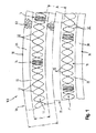
撚り合わされ、又は縒り合わされて、各々が絶縁(図示せず)された2本の導体(素線)32が、ケーブル10,20に各々伸びる様子が示される。撚り合わせた2本の線は、各々撚り線群11,21を形成する。言い換えれば、撚り線群の素線は互いの周りにねじ状又は螺旋状に巻かれる。完全に回転する毎に、撚り線は、各々、ケーブルの長手方向に一撚り長さ分前進する。
A state is shown in which two conductors (element wires) 32 that are twisted or twisted and insulated (not shown) each extend to the
第1ケーブル10は、ツイストペアケーブルであり、2本の撚り合わせた導体32を含む丁度1本の撚り線群11を含む。ケーブル10を形成するために、撚り線群11は、絶縁材料製のケーブルシース15によって包囲され、それにより、ケーブルシースの直径Yは約3.2mmである。別の直径も代替的に可能である。ケーブルシース15は、付加的なケーブルシース36の形態のスペーサ30によって包囲され、それは内側のケーブルシース15を同軸に包囲する。
The
第2ケーブル20も同様にツイストペアケーブルであり、2本の撚り合わせた導体32を含む丁度1本の撚り線群21を含む。撚り線群21は、絶縁材料製のケーブルシース25によって包囲される。ケーブルシース25は、付加的なケーブルシース38の形態のスペーサ34によって包囲され、それは内側のケーブルシース25を同軸に包囲する。
The
2本のケーブル10,20の撚り線群11,21の撚り長さは、ケーブルの長手方向において最小撚り長さと最大撚り長さの間で正弦波状に変化し、その結果、最小撚り長さの撚り部分14と最大撚り長さの撚り部分18が形成される。これは、撚り線群11,21間のクロストークを低減する。
The twist lengths of the
2本のケーブル10,20の図示された部分は、付加的なケーブルシース36,38の外側が互いに接するように、互いに密接して配置されている。代替的に、2つの付加的なケーブルシース36,38の間に少なくとも部分的に自由空間が配設されてもよい。この場合、2本の撚り線群11,21間の可能な最小間隔Aを図示するために、2つの付加的なケーブルシース36,38が密接して隣接した図が選択された。図から明白に判るように、この可能な限り最小の間隔Aは、2つの付加的なケーブルシース36,38によって、2つの付加的なケーブルシース36,38の合計厚さに対応する寸法だけ拡大される。2本の撚り線群11,21間の間隔Aが大きくなればなるほど、2本の撚り線群11,21で伝送される信号間のエイリアンクロストークがより有効に減少される。
The illustrated portions of the two
図示の実施形態において、ケーブルシース15,25の直径Yは、いずれの場合にも約3.2mmであるが、付加的なケーブルシース36,38の直径Xは4〜5ミリメートルの間となる。撚り線群11,21間の望まれるクロストーク減少に従って、別の寸法が可能である。
In the illustrated embodiment, the diameter Y of the
付加的なケーブルシース36,38は、いずれの場合も、発泡プラスチックから構成され、エアポケットにより参照番号60で示される。これは、拡大したケーブル径Yにも拘らず軽量なケーブルをもたらす。
The
対照的に、内側ケーブルシース15,25は、従来の(非発泡性)プラスチックから構成される。
In contrast, the
付加的なケーブルシース36,38は、既存のケーブルのケーブルシース15,25に後から施すことができ、例えば、ケーブルシース15,25に吹き付けることができる。代替的に、付加的なケーブルシース36,38は、内側ケーブルシース15,25上にスリーブのように押し込んでも、または側部から嵌められてもよい。
付加的なケーブルシース36,38はケーブルの全長にわたって延在し、その結果、隣接するケーブル10,20の間の撚り線群間の最小間隔Aが、ケーブルの全長にわたり保証される。
The
本発明は、説明した代表的実施形態に限定されない。例えば、本発明に係る配列は、隣り合って伸びる2本より多いケーブルで形成されてもよい。ツイストペアケーブルの代わりに、4本線で形成された撚り線群を有するスターカッドケーブルを用いてもよい。付加的なケーブルシースの代わりに、必ずしもケーブルの全長にわたって延在しなくてもよい剛性スリーブ又は別の形態のスペーサを配設してもよい。 The invention is not limited to the exemplary embodiments described. For example, the arrangement according to the invention may be formed with more than two cables extending side by side. Instead of the twisted pair cable, a star quad cable having a twisted wire group formed of four wires may be used. Instead of an additional cable sheath, a rigid sleeve or another form of spacer may be provided that does not necessarily extend over the entire length of the cable.
Claims (10)
前記2本のケーブル(10,20)の前記撚り線群(11,21)間の最小間隔(A)を拡大させるために、前記ケーブルシース(15,25)のうち少なくとも一方の外側にスペーサ(30)が配置されることを特徴とする配列。 An arrangement (100) of at least two cables (10, 20) extending adjacent to each other, wherein the first cable (10) and the second cable (20) are twisted together with two or more conductors ( 32) each having at least one strand group (11, 21) having a common cable sheath (15, 25) surrounding the strand group,
In order to increase the minimum distance (A) between the strands (11, 21) of the two cables (10, 20), a spacer (15) is provided outside at least one of the cable sheaths (15, 25). 30) arranged.
前記ケーブルシース(15,25)の各々の外側にスペーサ(30,34)が配置されることを特徴とする配列。 The arrangement according to claim 1, wherein
An arrangement in which spacers (30, 34) are arranged on the outside of each of the cable sheaths (15, 25).
前記スペーサ(30,34)は、前記ケーブルシース(15,25)を同軸に包囲する、好ましくは円形又は楕円形の外形を有するスリーブであることを特徴とする配列。 An arrangement according to claim 1 or claim 2, wherein
Arrangement characterized in that the spacer (30, 34) is a sleeve having a circular or elliptical outer shape, which coaxially surrounds the cable sheath (15, 25).
前記スリーブは、ケーブル(10,20)の全長の30%超、好ましくは50%超、特に好ましくは75%超、特にケーブルの全長にわたり延在することを特徴とする配列。 The arrangement according to claim 3,
Arrangement characterized in that the sleeve extends over 30% of the total length of the cable (10, 20), preferably over 50%, particularly preferably over 75%, in particular over the entire length of the cable.
前記スペーサは、前記ケーブルシース(15,25)の外側に配置された付加的なケーブルシース(36,38)であることを特徴とする配列。 In the arrangement according to claim 3 or claim 4,
The arrangement is characterized in that the spacer is an additional cable sheath (36, 38) arranged outside the cable sheath (15, 25).
前記スペーサ(30,34)は、非導電性材料、好ましくはプラスチック材料及び/又は発泡材料、特に発泡PP等の発泡プラスチック製であることを特徴とする配列。 In the arrangement according to any one of claims 1 to 5,
Arrangement characterized in that the spacers (30, 34) are made of a non-conductive material, preferably a plastic material and / or a foam material, in particular a foam plastic such as foam PP.
前記スペーサ(30,34)の外径(X)は、前記ケーブルシース(15,25)の外径(Y)の1.25倍以上、特に1.5倍以上であることを特徴とする配列。 The sequence according to any one of claims 1 to 6,
The outer diameter (X) of the spacer (30, 34) is 1.25 times or more, particularly 1.5 times or more, the outer diameter (Y) of the cable sheath (15, 25). .
前記スペーサ(30,34)の外径(X)は、3.5mm超10mm未満、特に4mm超5mm未満である、及び/又は、前記ケーブルシース(15,25)の外径(Y)は、2mm超3.5mm未満であることを特徴とする配列。 The arrangement according to claim 7,
The outer diameter (X) of the spacer (30, 34) is more than 3.5 mm and less than 10 mm, in particular more than 4 mm and less than 5 mm, and / or the outer diameter (Y) of the cable sheath (15, 25) is An arrangement characterized by being more than 2 mm and less than 3.5 mm.
前記撚り線群(11,21)は、撚り合わせた導体対(12,22)で各々構成される、及び/又は、前記ケーブル(10,20)は、各々ツイストペアケーブルであることを特徴とする配列。 The sequence according to any one of claims 1 to 8,
The twisted wire groups (11, 21) are each composed of twisted conductor pairs (12, 22), and / or the cables (10, 20) are each twisted pair cables. An array.
2本を超える、特に5本以上のケーブル(10,20)を収容したケーブル束の形態であり、好ましくは全てのケーブルは同一平面内に延在しない配列。 The sequence according to any one of claims 1 to 9,
It is in the form of a cable bundle containing more than two, in particular five or more cables (10, 20), preferably an arrangement in which all cables do not extend in the same plane.
Applications Claiming Priority (3)
| Application Number | Priority Date | Filing Date | Title |
|---|---|---|---|
| DE202014003291.2U DE202014003291U1 (en) | 2014-04-16 | 2014-04-16 | cable assembly |
| DE202014003291.2 | 2014-04-16 | ||
| PCT/EP2015/000754 WO2015158421A1 (en) | 2014-04-16 | 2015-04-09 | Cable arrangement |
Publications (1)
| Publication Number | Publication Date |
|---|---|
| JP2017517096A true JP2017517096A (en) | 2017-06-22 |
Family
ID=51226544
Family Applications (1)
| Application Number | Title | Priority Date | Filing Date |
|---|---|---|---|
| JP2016562557A Pending JP2017517096A (en) | 2014-04-16 | 2015-04-09 | Cable arrangement |
Country Status (9)
| Country | Link |
|---|---|
| US (1) | US20170040087A1 (en) |
| EP (1) | EP3132513B1 (en) |
| JP (1) | JP2017517096A (en) |
| KR (1) | KR20160144356A (en) |
| CN (1) | CN106165225A (en) |
| CA (1) | CA2941894A1 (en) |
| DE (1) | DE202014003291U1 (en) |
| TW (1) | TWM508828U (en) |
| WO (1) | WO2015158421A1 (en) |
Families Citing this family (8)
| Publication number | Priority date | Publication date | Assignee | Title |
|---|---|---|---|---|
| DE202015005042U1 (en) | 2015-07-14 | 2015-09-09 | Rosenberger Hochfrequenztechnik Gmbh & Co. Kg | Connector assembly with coding |
| US10237654B1 (en) | 2017-02-09 | 2019-03-19 | Hm Electronics, Inc. | Spatial low-crosstalk headset |
| NL2018988B1 (en) * | 2017-05-29 | 2018-12-07 | Use System Eng Holding B V | Twisted pair cable and CEDD system comprising such a cable |
| US11075488B2 (en) | 2019-11-25 | 2021-07-27 | TE Connectivity Services Gmbh | Impedance control connector with dielectric seperator rib |
| US11146010B2 (en) | 2019-12-09 | 2021-10-12 | TE Connectivity Services Gmbh | Overmolded contact assembly |
| US11011875B1 (en) | 2019-12-10 | 2021-05-18 | TE Connectivity Services Gmbh | Electrical cable braid positioning clip |
| US10978832B1 (en) | 2020-02-07 | 2021-04-13 | TE Connectivity Services Gmbh | Protection member to protect resilient arms of a contact assembly from stubbing |
| US11296464B2 (en) | 2020-02-14 | 2022-04-05 | TE Connectivity Services Gmbh | Impedance control connector |
Citations (1)
| Publication number | Priority date | Publication date | Assignee | Title |
|---|---|---|---|---|
| JP2002157926A (en) * | 2000-11-17 | 2002-05-31 | Sumitomo Wiring Syst Ltd | Twisted pair cable |
Family Cites Families (23)
| Publication number | Priority date | Publication date | Assignee | Title |
|---|---|---|---|---|
| US3735022A (en) * | 1971-09-22 | 1973-05-22 | A Estep | Interference controlled communications cable |
| US6392152B1 (en) * | 1996-04-30 | 2002-05-21 | Belden Communications | Plenum cable |
| FR2776120B1 (en) * | 1998-03-12 | 2000-04-07 | Alsthom Cge Alcatel | FLEXIBLE LOW CROSS CABLE |
| US6150612A (en) * | 1998-04-17 | 2000-11-21 | Prestolite Wire Corporation | High performance data cable |
| US6300573B1 (en) * | 1999-07-12 | 2001-10-09 | The Furukawa Electric Co., Ltd. | Communication cable |
| US7196271B2 (en) * | 2002-03-13 | 2007-03-27 | Belden Cdt (Canada) Inc. | Twisted pair cable with cable separator |
| US20030205402A1 (en) * | 2002-05-01 | 2003-11-06 | Fujikura Ltd. | Data transmission cable |
| CN103124189A (en) * | 2003-07-11 | 2013-05-29 | 泛达公司 | Alien crosstalk suppression with enhanced patch cord |
| US20050133246A1 (en) * | 2003-12-22 | 2005-06-23 | Parke Daniel J. | Finned Jackets for lan cables |
| KR100603087B1 (en) * | 2004-07-22 | 2006-07-20 | 엘에스전선 주식회사 | Utp cable assembly having means for preventing cross talk |
| US7358436B2 (en) * | 2004-07-27 | 2008-04-15 | Belden Technologies, Inc. | Dual-insulated, fixed together pair of conductors |
| US7432446B2 (en) * | 2005-09-28 | 2008-10-07 | Symbol Technologies, Inc. | Coiled electronic article surveillance (EAS) cable |
| US7145080B1 (en) * | 2005-11-08 | 2006-12-05 | Hitachi Cable Manchester, Inc. | Off-set communications cable |
| GB2435124B (en) * | 2006-02-13 | 2008-01-02 | Brand Rex Ltd | Improvements in and Relating to Electrical Cables |
| US7271344B1 (en) * | 2006-03-09 | 2007-09-18 | Adc Telecommunications, Inc. | Multi-pair cable with channeled jackets |
| US7375284B2 (en) * | 2006-06-21 | 2008-05-20 | Adc Telecommunications, Inc. | Multi-pair cable with varying lay length |
| JP2008078082A (en) * | 2006-09-25 | 2008-04-03 | Hitachi Cable Ltd | Metallic cable |
| ATE523884T1 (en) | 2008-06-02 | 2011-09-15 | Nexans | SPIRAL ELECTRICAL CABLE |
| US20100084157A1 (en) * | 2008-10-03 | 2010-04-08 | Sure-Fire Electrical Corporation | Digital audio video cable |
| FR2949274B1 (en) | 2009-08-19 | 2012-03-23 | Nexans | DATA COMMUNICATION CABLE |
| CN101694786A (en) * | 2009-10-21 | 2010-04-14 | 上海汉欣电线电缆有限公司 | Piece-separating type central framework cable |
| CN202584911U (en) * | 2012-03-21 | 2012-12-05 | 江苏亨通线缆科技有限公司 | Data cable of broadband and high capacity for local area network |
| CN203218031U (en) * | 2013-03-19 | 2013-09-25 | 江苏东强股份有限公司 | Multi-strand digital communication cable |
-
2014
- 2014-04-16 DE DE202014003291.2U patent/DE202014003291U1/en not_active Expired - Lifetime
-
2015
- 2015-04-09 JP JP2016562557A patent/JP2017517096A/en active Pending
- 2015-04-09 CA CA2941894A patent/CA2941894A1/en not_active Abandoned
- 2015-04-09 TW TW104205257U patent/TWM508828U/en not_active IP Right Cessation
- 2015-04-09 US US15/304,200 patent/US20170040087A1/en not_active Abandoned
- 2015-04-09 CN CN201580019484.7A patent/CN106165225A/en active Pending
- 2015-04-09 WO PCT/EP2015/000754 patent/WO2015158421A1/en active Application Filing
- 2015-04-09 EP EP15717093.7A patent/EP3132513B1/en active Active
- 2015-04-09 KR KR1020167025540A patent/KR20160144356A/en unknown
Patent Citations (1)
| Publication number | Priority date | Publication date | Assignee | Title |
|---|---|---|---|---|
| JP2002157926A (en) * | 2000-11-17 | 2002-05-31 | Sumitomo Wiring Syst Ltd | Twisted pair cable |
Also Published As
| Publication number | Publication date |
|---|---|
| WO2015158421A8 (en) | 2016-01-14 |
| US20170040087A1 (en) | 2017-02-09 |
| CN106165225A (en) | 2016-11-23 |
| KR20160144356A (en) | 2016-12-16 |
| WO2015158421A1 (en) | 2015-10-22 |
| DE202014003291U1 (en) | 2014-07-04 |
| EP3132513B1 (en) | 2019-11-20 |
| EP3132513A1 (en) | 2017-02-22 |
| TWM508828U (en) | 2015-09-11 |
| CA2941894A1 (en) | 2015-10-22 |
Similar Documents
| Publication | Publication Date | Title |
|---|---|---|
| JP2017517096A (en) | Cable arrangement | |
| US6297454B1 (en) | Cable separator spline | |
| JP5351642B2 (en) | cable | |
| JP5343960B2 (en) | Multi-core cable | |
| JP5870980B2 (en) | Multi-core cable | |
| JP6573893B2 (en) | Cable configuration | |
| CN101299357B (en) | Improved utp cable | |
| US20150075834A1 (en) | Cable with twisted pairs of insulated conductors | |
| EP0946951A1 (en) | Multiple twisted pair data cable with geometrically concentric cable groups | |
| WO2011001798A1 (en) | Shielded electric wire | |
| JP2011258330A (en) | Twisted pair cable | |
| CN108352226A (en) | data cable for high speed data transfer | |
| JP2018067435A (en) | Second core parallel cable | |
| US10418153B2 (en) | Fabricatable data transmission cable | |
| JP5929484B2 (en) | Multi-core cable and manufacturing method thereof | |
| KR20190062105A (en) | Cable provided with braided shield | |
| EP3594970B1 (en) | Routing structure of two-core parallel shielded electric wire | |
| US9786417B2 (en) | Multi-core cable and method of manufacturing the same | |
| KR20160000286U (en) | Multicore cable | |
| KR101160160B1 (en) | Utp cable for high speed communication | |
| JP2016110730A (en) | Multicore cable | |
| CN208298613U (en) | A kind of novel seven classes cable | |
| CN106887275A (en) | Multi-core cable | |
| TWM545343U (en) | Multi-core cable | |
| KR20120057182A (en) | Utp cable improved in separator structure |
Legal Events
| Date | Code | Title | Description |
|---|---|---|---|
| A621 | Written request for application examination |
Free format text: JAPANESE INTERMEDIATE CODE: A621 Effective date: 20180316 |
|
| A871 | Explanation of circumstances concerning accelerated examination |
Free format text: JAPANESE INTERMEDIATE CODE: A871 Effective date: 20180316 |
|
| A975 | Report on accelerated examination |
Free format text: JAPANESE INTERMEDIATE CODE: A971005 Effective date: 20180410 |
|
| A131 | Notification of reasons for refusal |
Free format text: JAPANESE INTERMEDIATE CODE: A131 Effective date: 20180417 |
|
| A521 | Request for written amendment filed |
Free format text: JAPANESE INTERMEDIATE CODE: A523 Effective date: 20180608 |
|
| A02 | Decision of refusal |
Free format text: JAPANESE INTERMEDIATE CODE: A02 Effective date: 20180724 |