JP2016110730A - Multicore cable - Google Patents
Multicore cable Download PDFInfo
- Publication number
- JP2016110730A JP2016110730A JP2014244656A JP2014244656A JP2016110730A JP 2016110730 A JP2016110730 A JP 2016110730A JP 2014244656 A JP2014244656 A JP 2014244656A JP 2014244656 A JP2014244656 A JP 2014244656A JP 2016110730 A JP2016110730 A JP 2016110730A
- Authority
- JP
- Japan
- Prior art keywords
- wires
- coaxial
- electric wires
- cable
- jacket
- Prior art date
- Legal status (The legal status is an assumption and is not a legal conclusion. Google has not performed a legal analysis and makes no representation as to the accuracy of the status listed.)
- Pending
Links
Images

Abstract
Description
本発明は、多芯ケーブル、より詳細には、複数本の同軸ケーブルおよびその他の絶縁電線を集合させ、その外側を外被で覆ってなる多芯ケーブルに関する。 The present invention relates to a multicore cable, and more particularly, to a multicore cable in which a plurality of coaxial cables and other insulated wires are assembled and the outside is covered with a jacket.
高速デジタル信号等を伝送する複数本の同軸電線を集合し、その外側を外被で覆ってなる多芯ケーブルが知られている。この多芯ケーブルには、同軸電線の他に、他の絶縁電線、例えば電源用の絶縁電線や制御信号用の絶縁電線等を含めた複合ケーブルとして構成されたものがある。 A multi-core cable is known in which a plurality of coaxial electric wires that transmit high-speed digital signals and the like are assembled and the outer sides thereof are covered with a jacket. Some of these multicore cables are configured as composite cables including other insulated wires, for example, insulated wires for power supplies and insulated wires for control signals, in addition to coaxial wires.
例えば特許文献1には、対撚り信号線と、複数の信号線対と、電源線対とを備え、対撚り信号線と複数の信号線対と電源線対とが、これらの長手方向に垂直な断面で見た場合に、対撚り信号線の周囲を複数の信号線対および電源線対が囲むように束ねられている伝送ケーブルが開示されている。 For example, Patent Document 1 includes a twisted signal line, a plurality of signal line pairs, and a power line pair, and the twisted signal line, the plurality of signal line pairs, and the power line pair are perpendicular to the longitudinal direction thereof. A transmission cable is disclosed that is bundled so that a plurality of signal line pairs and a power supply line pair surround a twisted signal line when viewed in a simple cross section.
また、特許文献2には、複数のフラットケーブルを有する集合ケーブルコアと、集合ケーブルコアの外周に設けられる電磁シールド部と、電磁シールド部の外周に設けられる外被層とを備える集合ケーブルが開示されている。各フラットケーブルは、複数の同軸ケーブルを略平行に1列に配列したフラットケーブルコアと、フラットケーブルコアの外周に合成樹脂を略全面被覆して形成され、複数の同軸ケーブルを拘束するシース層と、を有する。
同軸電線や絶縁電線を複数集合させて外被を被覆した多芯ケーブルでは、ケーブル径はできるだけ小さくし、ケーブル厚を薄くしたいという要求がある。また、多芯ケーブルにおいては、取扱い性向上のためにケーブルの柔軟性が求められる。
しかしながら、断面が丸い形状のまま複数の電線を集合させると、その多芯ケーブルに含まれる電線の数が増えるに従ってケーブル径が大きくなり太くなり、また柔軟性も低下して取り扱い性が悪化する。
In a multi-core cable in which a plurality of coaxial wires and insulated wires are gathered to cover a jacket, there is a demand to make the cable diameter as small as possible and to reduce the cable thickness. In addition, in a multicore cable, the flexibility of the cable is required to improve handling.
However, when a plurality of electric wires are assembled with a round cross section, the cable diameter increases and becomes thicker as the number of electric wires included in the multicore cable increases, and the flexibility also decreases, resulting in poor handling.
また、多芯ケーブルの電線として、シールド付きの対撚り線であるSTP(Shielded twist pair)ケーブルや、シールドテープが巻かれている2芯平行電線が使用されていると、シールド層やシールドテープにより1体化された電線により多芯ケーブルの柔軟性が阻害される。 In addition, if the STP (Shielded twist pair) cable, which is a shielded twisted pair wire, or a 2-core parallel wire wound with shielding tape is used as the electric wire of the multicore cable, The flexibility of the multi-core cable is hindered by the integrated electric wire.
特許文献1のケーブルでは、複線の電線を集合させるに際して断面が円形のケーブルを構成するため、その径が増大し、取扱性や柔軟性を阻害する。特許文献2はさらに多くの電線を含む構成が示唆されない。
In the cable of Patent Document 1, a cable having a circular cross section is formed when the double-wired electric wires are assembled, so that the diameter increases, and handling and flexibility are hindered.
本発明は、上述した実状に鑑みてなされたもので、同軸電線や絶縁電線を複数集合させて外被で被覆した多芯ケーブルにおいて、ケーブル径の増大を抑えて、柔軟性および取扱い性を向上させた多芯ケーブルの提供を目的とする。 The present invention has been made in view of the above-described circumstances, and in a multi-core cable in which a plurality of coaxial wires and insulated wires are collected and covered with an outer sheath, an increase in cable diameter is suppressed, and flexibility and handleability are improved. The purpose is to provide a multi-core cable.
本発明による多芯ケーブルは、同軸電線および絶縁電線を含む複数の電線と、該複数の電線の周囲を覆う外被とを有する多芯ケーブルであって、前記複数の電線が2列以上並列され、該並列された前記電線のうち1対の同軸電線同士が密接して配置され、前記多芯ケーブルの長手方向に直交する断面において、前記外被は、矩形の4つの角部が丸められた形状を有し、前記外被の4つの角部の内面側にグランド線となる絶縁電線が配置され、前記同軸電線の中心導体の断面積が0.004mm2〜0.05mm2であり、前記外被の厚さが0.4mm〜1.0mmである、多芯ケーブルである。 A multi-core cable according to the present invention is a multi-core cable having a plurality of wires including coaxial wires and insulated wires, and an outer sheath covering the periphery of the plurality of wires, wherein the plurality of wires are arranged in parallel in two or more rows. In the cross-section perpendicular to the longitudinal direction of the multi-core cable, the outer cover is rounded at four corners of the rectangle, in which a pair of coaxial electric wires are closely arranged among the paralleled electric wires. shaped, insulated wire becomes the ground lines are arranged on the inner surface of the envelope of the four corners, the cross-sectional area of the center conductor of the coaxial cable is 0.004mm 2 ~0.05mm 2, wherein This is a multi-core cable having a jacket thickness of 0.4 mm to 1.0 mm.
本発明によれば、同軸電線や絶縁電線を複数集合させて外被で被覆した多芯ケーブルにおいて、ケーブル径の増大を抑えて、柔軟性および取扱い性を向上させた多芯ケーブルの提供することができる。 According to the present invention, in a multicore cable in which a plurality of coaxial electric wires and insulated wires are assembled and covered with a jacket, an increase in the cable diameter is suppressed, and a multicore cable with improved flexibility and handleability is provided. Can do.
最初に本発明の実施態様を列記して説明する。
本願の多芯ケーブルに係る発明は、同軸電線および絶縁電線を含む複数の電線と、該複数の電線の周囲を覆う外被とを有する多芯ケーブルであって、前記複数の電線が2列以上並列され、該並列された前記電線のうち1対の同軸電線同士が密接して配置され、前記多芯ケーブルの長手方向に直交する断面において、前記外被は、矩形の4つの角部が丸められた形状を有し、前記外被の4つの角部の内面側にグランド線となる絶縁電線が配置され、前記同軸電線の中心導体の断面積が0.004mm2〜0.05mm2であり、前記外被の厚さが0.4mm〜1.0mmである、多芯ケーブルである。これにより、ケーブル径の増大および柔軟性の悪化を抑えて、取扱い性を向上させる多芯ケーブルを提供することができる。
First, embodiments of the present invention will be listed and described.
The invention related to the multi-core cable of the present application is a multi-core cable having a plurality of electric wires including coaxial wires and insulated wires, and a jacket covering the periphery of the plurality of electric wires, wherein the plurality of electric wires are two or more rows. A pair of coaxial wires are arranged in close contact with each other, and in the cross section perpendicular to the longitudinal direction of the multi-core cable, the jacket is rounded at four corners of a rectangle. has been shape, insulated wire becomes the ground lines are arranged on the inner surface of the envelope of the four corners, the cross-sectional area of the center conductor of the coaxial cable is located at 0.004mm 2 ~0.05mm 2 The multi-core cable has a thickness of the jacket of 0.4 mm to 1.0 mm. Thereby, the increase in a cable diameter and the deterioration of a softness | flexibility can be suppressed, and the multicore cable which improves handleability can be provided.
前記複数の電線が2列に配列され、全ての前記電線が前記外被の内面に接していることが好ましい。これにより、多芯ケーブル内の電線の配置を安定させることができる。 Preferably, the plurality of electric wires are arranged in two rows, and all the electric wires are in contact with the inner surface of the jacket. Thereby, arrangement | positioning of the electric wire in a multicore cable can be stabilized.
前記並列した前記複数の電線のうち1列の電線において、1つの前記角部から他の角部まで、各電線が前記外被の内面に接するとともに、隣接する各電線が互いに接するように配置されることが好ましい。これにより、これにより、電線の配置を安定化させるとともに、ケーブル幅の増大化を抑えることができる。 In one row of the plurality of electric wires arranged in parallel, from one corner portion to another corner portion, each electric wire is in contact with the inner surface of the outer jacket, and adjacent electric wires are arranged in contact with each other. It is preferable. Thereby, it is possible to stabilize the arrangement of the electric wires and suppress an increase in the cable width.
前記並列した前記複数の電線のうち1列の電線において、電線が互いに接していない部分が存在することが好ましい。複数の電線の列を同じ幅にできない場合に、電線が互いに接していない部分でその電線列の幅を調整することができる。 Of the plurality of electric wires arranged in parallel, one row of electric wires preferably has a portion where the electric wires are not in contact with each other. When a plurality of electric wire rows cannot have the same width, the width of the electric wire row can be adjusted at a portion where the electric wires are not in contact with each other.
前記電線が互いに接していない部分に、介在となる繊維が充填されていることが好ましい。これにより、電線の配列が乱れないように安定化させることができる。 It is preferable that intervening fibers are filled in portions where the electric wires are not in contact with each other. Thereby, it can stabilize so that the arrangement | sequence of an electric wire may not be disturbed.
前記電線が並列した2列以上の各列に、同軸電線対が複数配置され、1つの列内の前記同軸電線対は互いに接しないことが好ましい。これにより、電線を集合させるときの配列の乱れを抑えることができる。 It is preferable that a plurality of coaxial electric wire pairs are arranged in each of two or more rows in which the electric wires are arranged in parallel, and the coaxial electric wire pairs in one row do not contact each other. Thereby, disorder of the arrangement | sequence when collecting an electric wire can be suppressed.
[本願発明の実施形態の詳細]
本発明に係る多芯ケーブルの具体例を、以下に図面を参照しつつ説明する。なお、本発明はこれらの例示に限定されるものではなく、特許請求の範囲によって示され、特許請求の範囲と均等の意味および範囲内での全ての変更が含まれる。
[Details of the embodiment of the present invention]
Specific examples of the multicore cable according to the present invention will be described below with reference to the drawings. In addition, this invention is not limited to these illustrations, is shown by the claim, and includes all the changes within the meaning and range equivalent to a claim.
図1は、本発明による多芯ケーブルの構成例を示す図である。図中、1は多芯ケーブル、2は同軸電線、3は同軸電線対、4はグランド線、5は他の絶縁電線、6は外被(シース)である。
多芯ケーブル1は、同軸電線および絶縁電線を含む複数の電線(同軸電線対3、グランド線4、他の絶縁電線5)が外被6により被覆されて構成されている。他の絶縁電線5としては、例えば低速信号伝送用電線、低速制御電信号用電線、電源線などを含めることができる。
FIG. 1 is a diagram showing a configuration example of a multicore cable according to the present invention. In the figure, 1 is a multi-core cable, 2 is a coaxial wire, 3 is a coaxial wire pair, 4 is a ground wire, 5 is another insulated wire, and 6 is a jacket (sheath).
The multi-core cable 1 is configured by covering a plurality of electric wires (
外被6は、ポリエチレン(PE)、ポリ塩化ビニル(PVC)、エチレン酢酸ビニル共重合体(EVA)、ポリウレタンなどの樹脂を用いて押出し成形により被覆成形され、その厚さは0.4mm〜1.0mmの範囲とされる。複数の電線が並列した形状を維持するためには、外被6には1定の強度が必要であり、また、耐久性の面からも1定以上の厚さが必要となる。このため外被6の厚さは0.4mm以上必要となる。また、外被6は、1.0mmを超える厚さになると柔軟性が低下し取扱い難くなるためその厚さの上限値を1mmとすることが好ましい。 The jacket 6 is coated and formed by extrusion molding using a resin such as polyethylene (PE), polyvinyl chloride (PVC), ethylene vinyl acetate copolymer (EVA), polyurethane, and the thickness is 0.4 mm to 1 mm. The range is 0.0 mm. In order to maintain a shape in which a plurality of electric wires are arranged in parallel, the jacket 6 needs to have a certain strength, and also needs a thickness of more than a certain thickness from the viewpoint of durability. For this reason, the thickness of the jacket 6 is required to be 0.4 mm or more. Moreover, since the softness | flexibility falls and it becomes difficult to handle when the thickness exceeds 1.0 mm, it is preferable that the upper limit of the thickness is 1 mm.
同軸電線対3は、中心導体を絶縁体で被覆した同軸電線2を2本平行に並列させて密接配置したものである。この例では同軸電線対3を5つ集合させているが、その集合数は限定されない。同軸電線対3は、位相が180°反転された信号を2本の同軸電線2に同時に入力して送信し、受信側で差分合成することで受信側で信号出力を2倍にすることができる。また、送信から受信に至る伝送経路途中で受けたノイズ信号は、1対の同軸電線2に等しく加えられているので、受信側で差動信号として出力したときにキャンセルされ、ノイズが除去される。同軸電線対3を並列させて密接配置することにより、同軸電線対3を構成する2本の同軸電線2を並行に密接配置することにより、2本の同軸電線間での信号の遅延時間差(スキュー)を小さくすることができる。また、同軸電線2を並列させてさらにシールドテープを巻かない構成により、シールド付きの対撚り線であるSTPケーブルや、シールドテープが巻かれている2芯平行電線に比較して、柔軟性を付与することができる。
The
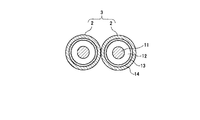
図2は、多芯ケーブルに適用する同軸電線対の構成を説明する図である。各同軸電線2は、中心導体11を絶縁体12で覆い、絶縁体12の外周に外部導体13を配置し、その外側を外被14で被覆した構成のものが用いられる。中心導体11には、例えば錫メッキ軟鋼線や錫メッキ銅合金線が用いられ、複数の素線を撚り合わせたもの、もしくは単線の構成のものが用いられる。いずれの場合にも中心導体11は、その断面積(長手方向に直交する断面の面積)が0.004mm2〜0.06mm2であり、AWG(American Wire Gauge)30〜40相当の外径とする。これにより情報処理装置間の高速デジタル信号伝送用に好適な細径の多芯ケーブルが得られる。
FIG. 2 is a diagram illustrating the configuration of a coaxial wire pair applied to a multicore cable. Each
絶縁体12には、フッ素樹脂、例えばFEP(テトラフルオロエチレン−ヘキサフルオロプロピレン共重合体)、PFA(テトラフルオロエチレン−パーフロオロアルキルビニルエーテル共重合体)を用いることができ、好適にはこれらをフッ素化した耐熱性の高いフッ素樹脂が用いられる。フッ素化されたフッ素樹脂としては、末端基をフッ素化(−CF3)したフッ素樹脂を用いることができるが、完全にフッ素化したフッ素樹脂を適用してもよい。フッ素樹脂は薄肉加工性が良好であり、ケーブルの細径化に適している。またフッ素樹脂は、動摩擦係数が低いため耐屈曲特性が良好となる。
As the
外部導体13は、例えば錫メッキ軟鋼線等による素線を横巻き、もしくは編組したものであり、さらにシールド機能を向上させるために金属箔を併設する構造としてもよい
外被14は、ポリエステル(PET)テープなどの樹脂テープを巻き付けて形成される。またフッ素樹脂等の樹脂材を押出し被覆成形してもよい。
The
上記構成において、本発明に係る実施形態の多芯ケーブル1は、同軸電線2および絶縁電線(グランド線4、他の絶縁電線5)を含む複数の電線と、その複数の電線の周囲を覆う外被6とを有し、複数の電線が2列以上並列される。図1の構成は、複数の電線が上段と下段の2列に並列されているが、3列以上で並列させたものであってもよい。複数の電線を複数列で並列させることにより、多芯ケーブル1の外形形状をフラットにして、その厚さを薄くし、かつケーブル幅を広すぎない適正な大きさにすることができる。この場合、集合させる電線の数とその径に応じて多芯ケーブル1の幅(電線の並列方向の長さ)が大きくなるが、多芯ケーブル1の幅は、その多芯ケーブル1を接続するコネクタ幅より狭い幅であればよい。例えば多芯ケーブル1の幅を3mm以上10mm以下とすることができる。多芯ケーブルの厚さは例えば1.3mm以上3.8mmとすることができる。
In the above configuration, the multi-core cable 1 according to the embodiment of the present invention includes a plurality of electric wires including the coaxial
多芯ケーブル1の長手方向に直交する断面(図1)は、矩形の4隅の角部C1〜C4が丸められた形状を有している。つまり矩形の4つの角部外周にR形状が付与されている。ここでは、多芯ケーブル1は、その断面を矩形にして厚さを増大させないようにし、その矩形の4つの角部C1〜C4の外周面を丸めた形状として、角部の外周面をなだらかにしている。外被6の4つの角部C1〜C4のそれぞれの内面側に、グランド線4となる絶縁電線が配置される。グランド線4を4隅に設けることにより、多芯ケーブルの対称性が良くなり、ケーブルのグランド電位の安定化にとって好ましい。
外被6の内面は、グランド線4の形状に沿って丸められ、その形状に対応するように外被6の外周側の角部が丸められる。これにより、外被6が均一な厚さとなり、均一な柔軟性を付与する。
The cross section (FIG. 1) orthogonal to the longitudinal direction of the multicore cable 1 has a shape in which corners C1 to C4 at four corners of a rectangle are rounded. That is, an R shape is given to the outer periphery of the four corners of the rectangle. Here, the multi-core cable 1 has a rectangular cross section so as not to increase its thickness, and the outer peripheral surfaces of the four corners C1 to C4 of the rectangle are rounded to smooth the outer peripheral surface of the corners. ing. An insulated wire serving as the
The inner surface of the jacket 6 is rounded along the shape of the
複数列で並列配置された複数の電線(同軸電線2、グランド線4、他の絶縁電線5)は、その全ての電線が外被5の内面に接している。これにより、電線の配置が安定する。
複数列で並列した複数の電線は、各列の幅(並列方向の長さ)が一致するとは限らない。この場合、最も長い列の幅が、外被6の内面の幅に一致する。すなわち、並列した複数の電線のうち、いずれか1列の電線において、矩形形状の1つの角部から他の角部まで、各電線が外被6の内面に接し、その1列の各電線が互いに接するように配置されている。図1の例では、上下2列に配列された電線のうち、上段の電線は、角部C1から角部C2に到るまで、その列の全ての電線が外被6の内面に接するとともに、隣接する各電線が互いに接するように配置される。これにより、電線の配置を安定化させるとともに、ケーブル幅の増大化を抑えることができる。
All of the electric wires (coaxial
A plurality of electric wires arranged in parallel in a plurality of rows do not necessarily have the same width (length in the parallel direction). In this case, the width of the longest row matches the width of the inner surface of the jacket 6. That is, in any one row of the plurality of electric wires arranged in parallel, from one corner of the rectangular shape to the other corner, each wire touches the inner surface of the jacket 6 and each row of the wires is It arrange | positions so that it may mutually contact. In the example of FIG. 1, among the electric wires arranged in the upper and lower two rows, the upper electric wires are in contact with the inner surface of the jacket 6 until all the electric wires in the row reach the corner portion C2 from the corner portion C1. It arrange | positions so that each adjacent electric wire may mutually contact | connect. Thereby, the arrangement of the electric wires can be stabilized and the increase in the cable width can be suppressed.
また、並列配置された複数の電線のうち、いずれか1列の電線において、電線間が互いに接していない部分が存在する。図1の例では、上下2列に配列された電線のうち、下段の電線には、配列方向に隙間Gが生じている。隙間G以外の部分では、下段の電線は互いに隣接して配置され、電線間の配置を安定させる。
この隙間Gには、図示しない介在となる繊維を充填することができる。介在となる繊維としては、例えばスフ(スパンレーヨン)による繊維やPP(ポロプロピレン)繊維等を使用することができる。電線間の隙間Gに介在となる繊維を充填することにより、電線の配列が乱れないように安定化させることができる。
Moreover, in any one row of the plurality of electric wires arranged in parallel, there is a portion where the electric wires are not in contact with each other. In the example of FIG. 1, among the wires arranged in the upper and lower rows, the lower wire has a gap G in the arrangement direction. In the portion other than the gap G, the lower wires are arranged adjacent to each other to stabilize the arrangement between the wires.
The gap G can be filled with intervening fibers (not shown). As the intervening fiber, for example, a fiber made of sufu (span rayon), a PP (polypropylene) fiber, or the like can be used. By filling the gap G between the electric wires with intervening fibers, the arrangement of the electric wires can be stabilized so as not to be disturbed.
また、並列配置された複数の電線は、電線が並列した2列以上の各列に、同軸電線対3が複数配置され、1つの列内の同軸電線対3は互いに隣接しないように構成されている。図1の例では、上下2列に配列された電線のうち、上段の電線には3対の同軸電線対3が含まれているが、これら3対の同軸電線対は、上段の1列内では互いに隣接していない。同様に下段の電線には2対の同軸電線対3が含まれているが、これら2対の同軸電線対は、下段の1列内では互い隣接していない。
同軸電線2は、他の絶縁電線よりも径が大きい傾向がある。従って多芯ケーブル1内における電線の配列の対称性を良くするために、同軸電線対3を集中して配置することなく、列内では同軸電線対3が互いに隣接しないように配置することが好ましい。またこれにより、電線を集合させるときの配列の乱れが抑えられる。
The plurality of electric wires arranged in parallel are configured such that a plurality of coaxial electric wire pairs 3 are arranged in each of two or more rows in which the electric wires are arranged in parallel, and the coaxial electric wire pairs 3 in one row are not adjacent to each other. Yes. In the example of FIG. 1, among the electric wires arranged in two upper and lower rows, the upper electric wire includes three pairs of coaxial
The
上記の構成により、同軸電線や絶縁電線を複数集合させて外被で被覆した多芯ケーブルにおいて、ケーブル径の増大を抑えて、柔軟性および取扱い性を向上させた多芯ケーブルを提供することができる。 With the above configuration, in a multicore cable in which a plurality of coaxial wires and insulated wires are assembled and covered with a jacket, it is possible to provide a multicore cable with improved flexibility and handleability while suppressing an increase in cable diameter. it can.
1…多芯ケーブル、2…同軸電線、3…同軸電線対、4…グランド線、5…絶縁電線、11…中心導体、12…絶縁体、13…外部導体、14…外被。
DESCRIPTION OF SYMBOLS 1 ... Multi-core cable, 2 ... Coaxial electric wire, 3 ... Coaxial electric wire pair, 4 ... Ground wire, 5 ... Insulated electric wire, 11 ... Center conductor, 12 ... Insulator, 13 ... External conductor, 14 ... Jacket | cover.
Claims (6)
前記複数の電線が2列以上並列され、該並列された前記電線のうち1対の同軸電線が並列されて密接配置され、
前記多芯ケーブルの長手方向に直交する断面において、前記外被は、矩形の4つの角部が丸められた形状を有し、前記外被の4つの角部の内面側にグランド線となる絶縁電線が配置され、
前記同軸電線の中心導体の断面積が0.004mm2〜0.05mm2であり、前記外被の厚さが0.4mm〜1.0mmである、多芯ケーブル。 A multi-core cable having a plurality of wires including coaxial wires and insulated wires, and a jacket covering the periphery of the plurality of wires,
Two or more rows of the plurality of electric wires are juxtaposed, and a pair of coaxial electric wires among the juxtaposed electric wires are juxtaposed and arranged closely,
In the cross section orthogonal to the longitudinal direction of the multi-core cable, the jacket has a shape in which four corners of a rectangle are rounded, and an insulation that serves as a ground wire on the inner surface side of the four corners of the jacket The wires are placed,
The multi-core cable, wherein a cross-sectional area of a central conductor of the coaxial cable is 0.004 mm 2 to 0.05 mm 2 , and a thickness of the jacket is 0.4 mm to 1.0 mm.
The multi-core cable according to any one of claims 1 to 5, wherein a plurality of coaxial electric wire pairs are arranged in each of two or more rows in which the electric wires are arranged in parallel, and the coaxial electric wire pairs in one row do not contact each other. .
Priority Applications (1)
| Application Number | Priority Date | Filing Date | Title |
|---|---|---|---|
| JP2014244656A JP2016110730A (en) | 2014-12-03 | 2014-12-03 | Multicore cable |
Applications Claiming Priority (1)
| Application Number | Priority Date | Filing Date | Title |
|---|---|---|---|
| JP2014244656A JP2016110730A (en) | 2014-12-03 | 2014-12-03 | Multicore cable |
Publications (1)
| Publication Number | Publication Date |
|---|---|
| JP2016110730A true JP2016110730A (en) | 2016-06-20 |
Family
ID=56124594
Family Applications (1)
| Application Number | Title | Priority Date | Filing Date |
|---|---|---|---|
| JP2014244656A Pending JP2016110730A (en) | 2014-12-03 | 2014-12-03 | Multicore cable |
Country Status (1)
| Country | Link |
|---|---|
| JP (1) | JP2016110730A (en) |
Cited By (1)
| Publication number | Priority date | Publication date | Assignee | Title |
|---|---|---|---|---|
| CN114242306A (en) * | 2017-11-08 | 2022-03-25 | 株式会社自动网络技术研究所 | Electric wire conductor, covered electric wire, and wire harness |
-
2014
- 2014-12-03 JP JP2014244656A patent/JP2016110730A/en active Pending
Cited By (2)
| Publication number | Priority date | Publication date | Assignee | Title |
|---|---|---|---|---|
| CN114242306A (en) * | 2017-11-08 | 2022-03-25 | 株式会社自动网络技术研究所 | Electric wire conductor, covered electric wire, and wire harness |
| CN114242306B (en) * | 2017-11-08 | 2024-03-15 | 株式会社自动网络技术研究所 | Wire conductor, covered wire, and wire harness |
Similar Documents
| Publication | Publication Date | Title |
|---|---|---|
| JP5614428B2 (en) | Multi-core cable and manufacturing method thereof | |
| JP5343960B2 (en) | Multi-core cable | |
| JP5870980B2 (en) | Multi-core cable | |
| JP5761226B2 (en) | Multi-core cable and manufacturing method thereof | |
| JP6269718B2 (en) | Multi-core cable | |
| US9805844B2 (en) | Twisted pair cable with shielding arrangement | |
| EP2973613B1 (en) | Shielded cable with utp pair environment | |
| US20030106704A1 (en) | Electrical cable apparatus | |
| JP5900275B2 (en) | Cable for multi-pair differential signal transmission | |
| JP2016027547A (en) | Differential signal transmission cable and multicore differential signal transmission cable | |
| JP2017517096A (en) | Cable arrangement | |
| JP5825270B2 (en) | Multi-core cable | |
| JP5870979B2 (en) | Multi-core cable | |
| JP2011258330A (en) | Twisted pair cable | |
| JP2018067435A (en) | Second core parallel cable | |
| JP5929484B2 (en) | Multi-core cable and manufacturing method thereof | |
| JP2017033837A (en) | Flat cable and flat cable with connector | |
| CN110268483B (en) | Coaxial cable | |
| JP2016110730A (en) | Multicore cable | |
| JP3193295U (en) | Multi-core cable | |
| CN205564320U (en) | Multi -core cable | |
| CN210575204U (en) | Flexible six-type digital network communication cable | |
| JP6519324B2 (en) | Multi-core cable | |
| JP2017111895A (en) | Multicore cable |