JP2017516554A - Medical system - Google Patents
Medical system Download PDFInfo
- Publication number
- JP2017516554A JP2017516554A JP2016569628A JP2016569628A JP2017516554A JP 2017516554 A JP2017516554 A JP 2017516554A JP 2016569628 A JP2016569628 A JP 2016569628A JP 2016569628 A JP2016569628 A JP 2016569628A JP 2017516554 A JP2017516554 A JP 2017516554A
- Authority
- JP
- Japan
- Prior art keywords
- medical system
- bone
- patient
- medical
- reference unit
- Prior art date
- Legal status (The legal status is an assumption and is not a legal conclusion. Google has not performed a legal analysis and makes no representation as to the accuracy of the status listed.)
- Granted
Links
Images


Classifications
-
- A—HUMAN NECESSITIES
- A61—MEDICAL OR VETERINARY SCIENCE; HYGIENE
- A61B—DIAGNOSIS; SURGERY; IDENTIFICATION
- A61B34/00—Computer-aided surgery; Manipulators or robots specially adapted for use in surgery
- A61B34/20—Surgical navigation systems; Devices for tracking or guiding surgical instruments, e.g. for frameless stereotaxis
-
- A—HUMAN NECESSITIES
- A61—MEDICAL OR VETERINARY SCIENCE; HYGIENE
- A61B—DIAGNOSIS; SURGERY; IDENTIFICATION
- A61B17/00—Surgical instruments, devices or methods
- A61B17/14—Surgical saws
- A61B17/15—Guides therefor
- A61B17/154—Guides therefor for preparing bone for knee prosthesis
-
- A—HUMAN NECESSITIES
- A61—MEDICAL OR VETERINARY SCIENCE; HYGIENE
- A61B—DIAGNOSIS; SURGERY; IDENTIFICATION
- A61B17/00—Surgical instruments, devices or methods
- A61B17/14—Surgical saws
- A61B17/15—Guides therefor
- A61B17/154—Guides therefor for preparing bone for knee prosthesis
- A61B17/155—Cutting femur
-
- A—HUMAN NECESSITIES
- A61—MEDICAL OR VETERINARY SCIENCE; HYGIENE
- A61B—DIAGNOSIS; SURGERY; IDENTIFICATION
- A61B17/00—Surgical instruments, devices or methods
- A61B17/14—Surgical saws
- A61B17/15—Guides therefor
- A61B17/154—Guides therefor for preparing bone for knee prosthesis
- A61B17/157—Cutting tibia
-
- A—HUMAN NECESSITIES
- A61—MEDICAL OR VETERINARY SCIENCE; HYGIENE
- A61B—DIAGNOSIS; SURGERY; IDENTIFICATION
- A61B90/00—Instruments, implements or accessories specially adapted for surgery or diagnosis and not covered by any of the groups A61B1/00 - A61B50/00, e.g. for luxation treatment or for protecting wound edges
- A61B90/39—Markers, e.g. radio-opaque or breast lesions markers
-
- A—HUMAN NECESSITIES
- A61—MEDICAL OR VETERINARY SCIENCE; HYGIENE
- A61B—DIAGNOSIS; SURGERY; IDENTIFICATION
- A61B17/00—Surgical instruments, devices or methods
- A61B17/56—Surgical instruments or methods for treatment of bones or joints; Devices specially adapted therefor
- A61B2017/568—Surgical instruments or methods for treatment of bones or joints; Devices specially adapted therefor produced with shape and dimensions specific for an individual patient
-
- A—HUMAN NECESSITIES
- A61—MEDICAL OR VETERINARY SCIENCE; HYGIENE
- A61B—DIAGNOSIS; SURGERY; IDENTIFICATION
- A61B34/00—Computer-aided surgery; Manipulators or robots specially adapted for use in surgery
- A61B34/10—Computer-aided planning, simulation or modelling of surgical operations
- A61B2034/108—Computer aided selection or customisation of medical implants or cutting guides
-
- A—HUMAN NECESSITIES
- A61—MEDICAL OR VETERINARY SCIENCE; HYGIENE
- A61B—DIAGNOSIS; SURGERY; IDENTIFICATION
- A61B34/00—Computer-aided surgery; Manipulators or robots specially adapted for use in surgery
- A61B34/20—Surgical navigation systems; Devices for tracking or guiding surgical instruments, e.g. for frameless stereotaxis
- A61B2034/2046—Tracking techniques
- A61B2034/2055—Optical tracking systems
-
- A—HUMAN NECESSITIES
- A61—MEDICAL OR VETERINARY SCIENCE; HYGIENE
- A61B—DIAGNOSIS; SURGERY; IDENTIFICATION
- A61B90/00—Instruments, implements or accessories specially adapted for surgery or diagnosis and not covered by any of the groups A61B1/00 - A61B50/00, e.g. for luxation treatment or for protecting wound edges
- A61B90/39—Markers, e.g. radio-opaque or breast lesions markers
- A61B2090/3983—Reference marker arrangements for use with image guided surgery
-
- B—PERFORMING OPERATIONS; TRANSPORTING
- B33—ADDITIVE MANUFACTURING TECHNOLOGY
- B33Y—ADDITIVE MANUFACTURING, i.e. MANUFACTURING OF THREE-DIMENSIONAL [3D] OBJECTS BY ADDITIVE DEPOSITION, ADDITIVE AGGLOMERATION OR ADDITIVE LAYERING, e.g. BY 3D PRINTING, STEREOLITHOGRAPHY OR SELECTIVE LASER SINTERING
- B33Y80/00—Products made by additive manufacturing
Landscapes
- Health & Medical Sciences (AREA)
- Surgery (AREA)
- Life Sciences & Earth Sciences (AREA)
- Engineering & Computer Science (AREA)
- Molecular Biology (AREA)
- Public Health (AREA)
- Veterinary Medicine (AREA)
- Biomedical Technology (AREA)
- Heart & Thoracic Surgery (AREA)
- Medical Informatics (AREA)
- Nuclear Medicine, Radiotherapy & Molecular Imaging (AREA)
- Animal Behavior & Ethology (AREA)
- General Health & Medical Sciences (AREA)
- Oral & Maxillofacial Surgery (AREA)
- Orthopedic Medicine & Surgery (AREA)
- Physical Education & Sports Medicine (AREA)
- Transplantation (AREA)
- Dentistry (AREA)
- Robotics (AREA)
- Pathology (AREA)
- Surgical Instruments (AREA)
- Prostheses (AREA)
Abstract
特に膝関節内プロテーゼを埋込むための医療用システムであって、外科用ナビゲーションシステムを使用してその空間位置が検出可能な少なくとも1つの医療用参照ユニットを含み、少なくとも1つの医療用参照ユニットが、担体要素上に配置又は形成されるとともに前記外科用ナビゲーションシステムの検出装置を使用して検出可能である少なくとも1つの外科用マーカ要素を含み、この少なくとも1つの医療用参照ユニットが、前記担体要素を担持する基体を含む医療用システムをその使用が簡素化されるようなやり方で改良するために、前記基体から離れる方を向くとともに、球体の表面の扇形であること及び平面状表面であることから外れる少なくとも1つの患者特有の骨接触面を前記基体が含み、前記少なくとも1つの骨接触面が、前記患者の骨表面に対応するやり方で形成されることが提案される。In particular, a medical system for implanting an intra-knee prosthesis comprising at least one medical reference unit whose spatial position can be detected using a surgical navigation system, wherein at least one medical reference unit comprises Including at least one surgical marker element disposed or formed on the carrier element and detectable using the detection device of the surgical navigation system, the at least one medical reference unit comprising the carrier element In order to improve the medical system comprising a substrate carrying a substrate in a manner that simplifies its use, it faces away from said substrate and is a sectoral and planar surface of the sphere The substrate includes at least one patient-specific bone contacting surface that is disengaged from the at least one bone contacting surface; It is proposed to be formed in a manner corresponding to the bone surface of the patient.
Description
本発明は、特に膝関節内プロテーゼを埋込むための医療用システムであって、外科用ナビゲーションシステムを使用してその空間位置を検出することのできる少なくとも1つの医療用参照ユニットを含み、少なくとも1つの医療用参照ユニットが、担体要素上に配置又は形成されるとともに外科用ナビゲーションシステムの検出装置を使用して検出することのできる少なくとも1つの外科用マーカ要素を含み、少なくとも1つの医療用参照ユニットが、担体要素を担持する基体を含む、医療用システムに関する。 The present invention is a medical system, particularly for implanting an intra-knee prosthesis, comprising at least one medical reference unit whose spatial position can be detected using a surgical navigation system, At least one medical reference unit including at least one surgical marker element disposed or formed on the carrier element and capable of being detected using the detection device of the surgical navigation system Relates to a medical system comprising a substrate carrying a carrier element.
このようなシステムが、例えばDE 10 2010 060 914 A1から知られている。患者の身体上に1つ以上の医療用参照ユニットを位置決めするためには、ナビゲーション支援型手術の開始時にまず、特徴点を例えばナビゲーション支援で触知することにより、患者の身体上の標認点を記録することが必要である。更に、介入前の患者の解剖学的構造の画像データが存在する場合に、これらの画像データをナビゲーション支援のやり方で測定した患者の身体上の標認点又は特徴点に一致させることは困難である。特に、このことは外科的介入の開始時にかなりの時間を奪うのであり、従って多大の費用に結び付く。 Such a system is known, for example, from DE 10 2010 060 914 A1. In order to position one or more medical reference units on the patient's body, at the beginning of the navigation-assisted surgery, first the feature points on the patient's body are touched by, for example, navigation assistance. It is necessary to record. Furthermore, if there is image data of the patient's anatomy before the intervention, it is difficult to match these image data to the landmarks or feature points on the patient's body measured in a navigation-assisted manner. is there. In particular, this takes a considerable amount of time at the start of the surgical intervention and is therefore very expensive.
本特許明細書において使用するような用語「外科用マーカ要素」は、特に、例えば担体要素上のその位置が既知である規定の窪みの形態の規定の参照点を包含することを意味する。このような参照点は、例えば、ナビゲーション型触知器具により触知することができる。これによって触知器具の空間位置を測定することにより、その空間位置に参照点を割り当てることができる。少なくとも1つの好ましくは3つの外科用マーカ要素を含む更なる参照ユニットが骨に固定されている場合、この更なる参照ユニットに関する規定の参照点の位置も既知となるため、骨が骨上の担体要素と共に移動する際であっても、更なる参照ユニットの場所及び配向を測定することにより、規定の参照点の位置を、ナビゲーションシステムを介していつでも測定することができる。 The term “surgical marker element” as used in this patent specification is meant in particular to encompass a defined reference point, for example in the form of a defined recess whose position on the carrier element is known. Such a reference point can be sensed by, for example, a navigation type tactile instrument. Thus, by measuring the spatial position of the tactile instrument, a reference point can be assigned to the spatial position. If a further reference unit comprising at least one and preferably three surgical marker elements is fixed to the bone, the position of the defined reference point with respect to this further reference unit is also known so that the bone is a carrier on the bone. Even when moving with the element, by measuring the location and orientation of the further reference unit, the position of the defined reference point can be measured at any time via the navigation system.
従って、冒頭に記載した種類のシステムを、その使用が簡素化されるように改良することが本発明の目的である。 Accordingly, it is an object of the present invention to improve a system of the kind described at the outset so that its use is simplified.
本発明によれば、この目的は、冒頭に記載した種類の医療用システムにおいて、前記基体から離れる方を向くとともに、球体の表面の扇形であるもの及び平面状表面であることから外れる少なくとも1つの患者特有の骨接触面を前記基体が含み、前記少なくとも1つの骨接触面が、前記患者の骨表面に対応するやり方で形成されることにより成就される。 According to the invention, this object is achieved in a medical system of the kind described at the outset, facing away from the base body and at least one deviating from being a fan-shaped surface of the sphere and a planar surface. This is accomplished by the patient including a patient-specific bone contacting surface, wherein the at least one bone contacting surface is formed in a manner corresponding to the bone surface of the patient.
提案する改良により、前記少なくとも1つの参照ユニットを患者の骨に接触させて規定のやり方で容易にかつ安全に置き、任意で特にこの骨に固定することが可能になる。従って、特に前記患者の骨の画像データを基に前記患者特有の骨接触面が生成されると、前記少なくとも1つの参照ユニットを前記患者の骨上で一意的に位置決めすることを確実にすることができる。この場合、前記外科的介入の前記開始時に前記少なくとも1つの参照ユニットの前記位置を付加的に前記患者の身体上に割り当てて参照させる必要はもはやない。ある意味で、このステップは、前記患者特有の骨接触面の構成を基に、前記少なくとも1つの外科用マーカ要素の、前記患者特有の骨接触面に対する前記位置の知識でもって、前記外科的介入の前記開始時のいかなる参照もこれが冗長になるであろうという点で成就される。好ましくは、前記患者特有の骨接触面は少なくとも3cm2の寸法を有する。前記患者特有の骨接触面が、それよりも一層大きいこと、例えば少なくとも6cm2であることが有利である。前記少なくとも1つの参照ユニットを前記患者の身体上で正確に位置決めすることは、前記患者特有の骨接触面が大きければ大きいほど、より安全かつ一意的に達成することができる。前記システムは、特に人工の膝関節、股関節、又は肩関節等の人工関節の埋込み用に使用することができる。この列挙は網羅的なものではない。 The proposed improvement makes it possible to place the at least one reference unit in contact with the patient's bone easily and safely in a defined manner and optionally in particular to this bone. Thus, ensuring that the at least one reference unit is uniquely positioned on the patient's bone, especially when the patient-specific bone contact surface is generated based on image data of the patient's bone Can do. In this case, it is no longer necessary to additionally assign the position of the at least one reference unit on the patient's body for reference at the start of the surgical intervention. In a sense, this step is based on the configuration of the patient-specific bone contact surface and with the knowledge of the position of the at least one surgical marker element relative to the patient-specific bone contact surface, the surgical intervention. Any reference at the start of this is accomplished in that this would be redundant. Preferably, the patient-specific bone contact surface has a dimension of at least 3 cm 2 . Advantageously, the patient-specific bone contact surface is even larger, for example at least 6 cm 2 . Accurate positioning of the at least one reference unit on the patient's body can be accomplished more safely and uniquely as the patient-specific bone contact surface is larger. The system can be used in particular for the implantation of artificial joints such as artificial knee joints, hip joints or shoulder joints. This list is not exhaustive.
前記基体と前記担体要素とが一体構成である又は共に解放不可能に接続されることが好適である。このことにより、前記担体要素と前記基体との間の相対位置、故に前記少なくとも1つのマーカ要素と前記患者特有の骨接触面との間の相対位置の変化が、直接、及び外科医又は前記外科医の補助スタッフにより、意図的にであっても意図的でなくても生じないようにされる。従って、全体的にみて前記システムのミスの生じ易さを最小にすることが可能である。 It is preferred that the base body and the carrier element are monolithic or connected together in a non-releasable manner. This allows a change in the relative position between the carrier element and the substrate, and hence the relative position between the at least one marker element and the patient-specific bone contact surface, directly and by the surgeon or the surgeon. Auxiliary staff will ensure that it does not occur intentionally or unintentionally. Therefore, it is possible to minimize the likelihood of system errors as a whole.
更に、前記基体と前記担体要素とが互いに解放可能に接続するように構成されることが有利なことがある。これにより、前記担体要素は上にある前記少なくとも1つのマーカ要素と共に複数回使用することができる。そうすれば、各患者用に患者特有の骨接触面を備えた、後に前記担体要素に接続することのできる1つ以上の基体を製造するだけでよい。 Furthermore, it may be advantageous that the substrate and the carrier element are configured to be releasably connected to each other. This allows the carrier element to be used multiple times with the at least one marker element on top. In doing so, it is only necessary to produce one or more substrates, each with a patient-specific bone contact surface for each patient, which can later be connected to the carrier element.
前記システムが、前記基体と前記担体要素とを連結位置において力ロック式及び/又は形状ロック式に連結するための連結装置を含むことが有利である。このような連結装置を用いれば、前記基体と前記担体要素とを規定のやり方で共に接続することができる。特に前記連結装置は、前記基体と前記担体要素との間で、一意的な連結を、即ちたった1つの仕方で行うことのできる連結を可能にするように構成することができる。 Advantageously, the system comprises a connection device for connecting the base body and the carrier element in a force-locking and / or shape-locking manner in the connection position. With such a coupling device, the substrate and the carrier element can be connected together in a defined manner. In particular, the connection device can be configured to allow a unique connection, i.e. a connection that can be made in only one way, between the substrate and the carrier element.
一方で前記基体上、他方で前記担体要素上に配置又は形成されるとともに、前記連結位置のときに係合状態にあり、非連結位置のときに係合状態にない第1及び第2連結要素を前記連結装置が含むことにより、前記連結装置の特に単純な構成を達成することができる。 First and second connecting elements which are arranged or formed on the base on the one hand and on the carrier element on the other hand and which are in the engaged state when in the connected position and not in the engaged state when in the unconnected position By including the connecting device, a particularly simple configuration of the connecting device can be achieved.
前記基体と前記担体要素とを単純かつ安全に連結するために、前記第1及び第2連結要素が、少なくとも1つの連結受けと、この連結受けと協働する対応する連結突起とを含むことが有利である。前記担体要素上又は前記基体上のいずれかに、又はこれらの両方の上に配置又は形成される2つ以上の連結受け又は2つ以上の連結突起があることを実現することができる。 In order to connect the base body and the carrier element simply and safely, the first and second connection elements include at least one connection receiver and a corresponding connection protrusion cooperating with the connection receiver. It is advantageous. It can be realized that there are two or more coupling receivers or two or more coupling projections arranged or formed either on the carrier element or on the substrate or on both.
本発明の別の好適な実施形態によれば、前記少なくとも1つの参照ユニットが、前記参照ユニットを骨に固定するための固締要素用に少なくとも1つの固締要素受けを含むことを実現することができる。このような参照ユニットは、規定のやり方で容易かつ安全に骨に固定することができる。 According to another preferred embodiment of the invention, it is realized that the at least one reference unit comprises at least one clamping element receiver for a clamping element for fixing the reference unit to the bone Can do. Such a reference unit can be fixed to the bone easily and safely in a defined manner.
前記少なくとも1つの固締要素受けが、前記基体上及び/又は前記担体要素上に配置又は形成されることが好適である。特にこのことは、前記基体又は前記担体要素が前記患者の骨に互いに別々に、任意で共に1つ以上の固締要素を使用して固定されることを可能にする。 Suitably, the at least one clamping element receiver is arranged or formed on the substrate and / or on the carrier element. In particular, this allows the substrate or the carrier element to be fixed to the patient's bone separately from each other, optionally together using one or more fastening elements.
前記少なくとも1つの固締要素受けは、特に開口の前記形態に構成される際、生産が単純になる。特に、固締要素受けは、孔の前記形態に構成することができる。前記基体又は前記担体要素の位置の変化を防止するために、前記基体上及び/又は前記担体要素上に、前記開口を延長するスリーブが配置又は形成されることが有利である。このスリーブは、骨ピン、骨ねじ、又は骨釘に対して特に良好な内部の誘導を提供する。特に前記スリーブは、前記骨固締要素を挿入する方向を予め決めておいて外科医に表示することもできる。 The at least one clamping element receiver is simple to produce, especially when configured in the form of an opening. In particular, the clamping element receiver can be configured in the form of the hole. In order to prevent a change in the position of the substrate or the carrier element, it is advantageous to arrange or form a sleeve extending the opening on the substrate and / or on the carrier element. This sleeve provides a particularly good internal guidance for bone pins, bone screws or bone nails. In particular, the sleeve can be indicated to the surgeon in a predetermined direction in which the bone anchoring element is inserted.
本発明の別の好適な実施形態によれば、前記医療用システムが、前記少なくとも1つの参照ユニットに解放可能に接続できる少なくとも1つの医療器具を含むことを実現することができる。この構成により、前記参照ユニットに例えば1つ以上の器具を接続することが可能になる。参照ユニットが規定のやり方で前記患者の身体に固定されると、前記少なくとも1つの参照ユニットに前記少なくとも1つの医療器具を規定のやり方で接続することにより、前記少なくとも1つの医療器具も前記患者の身体に、一意的に予め決めておいたやり方で固定することができる。 According to another preferred embodiment of the invention, it can be realized that the medical system comprises at least one medical instrument that can be releasably connected to the at least one reference unit. This configuration makes it possible to connect, for example, one or more instruments to the reference unit. When the reference unit is secured to the patient's body in a defined manner, the at least one medical device is also attached to the patient by connecting the at least one medical device to the at least one reference unit in a defined manner. It can be fixed to the body in a uniquely predetermined manner.
前記少なくとも1つの医療器具と前記少なくとも1つの参照ユニットとの間の解放可能な接続に備えておく特に単純な仕方とは、前記医療用システムが、前記少なくとも1つの医療器具と前記少なくとも1つの参照ユニットとを連結位置において、力ロック式及び/又は形状ロック式に連結するための連結装置を含むことである。 A particularly simple way to provide for a releasable connection between the at least one medical device and the at least one reference unit is that the medical system is configured to have the at least one medical device and the at least one reference. And including a connecting device for connecting the unit to the force-locking type and / or the shape-locking type at the connecting position.
一方で前記少なくとも1つの参照ユニット上、他方で前記少なくとも1つの医療器具上に配置又は形成されるとともに、前記連結位置のときに係合状態にあり、非連結位置のときに係合状態にない第1及び第2連結要素を前記連結装置が含むことが有利である。特に、前記連結装置の少なくとも1つの連結要素が前記少なくとも1つの参照ユニットの前記基体上に配置又は形成されることが有利である。このことにより、前記少なくとも1つの医療器具を前記参照ユニットの前記基体に連結することができる。従って、前記担体要素を特に前記基体から分離できる際、任意で前記担体要素は上にある前記少なくとも1つのマーカ要素と共に除去することも可能である一方で、前記基体は依然として前記患者の身体に固締したままにしておくことができる。 Arranged or formed on the at least one reference unit on the one hand and on the at least one medical instrument on the other hand and in an engaged state when in the connected position and not in an engaged state when in the unconnected position Advantageously, the coupling device comprises first and second coupling elements. In particular, it is advantageous for at least one coupling element of the coupling device to be arranged or formed on the substrate of the at least one reference unit. This allows the at least one medical instrument to be coupled to the base of the reference unit. Thus, when the carrier element can be separated from the substrate in particular, the carrier element can optionally be removed along with the at least one marker element thereon, while the substrate is still anchored to the patient's body. You can leave it tightened.
前記少なくとも1つの参照ユニットと前記少なくとも1つの医療器具とを共に接続する単純かつ安全な仕方とは、前記第1及び第2連結要素が、少なくとも1つの連結受けとこの連結受けと協働する少なくとも1つの対応する連結受けとを含むことである。 A simple and safe way to connect the at least one reference unit and the at least one medical device together is that the first and second coupling elements cooperate with at least one coupling receiver and at least the coupling receiver. One corresponding connection receiver.
特に前記連結受けと前記連結突起とは、これらの間で力ロック式及び/又は形状ロック式の接続が可能になるように構成することができる。 In particular, the connection receiver and the connection protrusion can be configured such that a force lock type and / or a shape lock type connection is possible between them.
前記医療器具を、前記少なくとも1つの参照ユニットとは無関係に任意で患者の骨に固定できるようにするために、前記少なくとも1つの医療器具が、前記少なくとも1つの医療器具を骨に固定するための固締要素用に少なくとも1つの器具固締要素受けを含むことが有利である。 In order to allow the medical device to be optionally fixed to a patient's bone independently of the at least one reference unit, the at least one medical device is for fixing the at least one medical device to the bone. It is advantageous to include at least one instrument clamping element receptacle for the clamping element.
前記少なくとも1つの器具固締要素受けは、好ましくは、開口の前記形態に構成される。特にこのような開口は、例えば孔の前記形態にして容易に生産することができる。 The at least one instrument clamping element receiver is preferably configured in the form of an opening. In particular, such openings can easily be produced, for example, in the form of the holes.
本発明の別の好適な実施形態によれば、前記少なくとも1つの医療器具が接触体を含み、この接触体が、前記接触体から離れる方を向くとともに、球体の表面の扇形であること及び平面状表面であることから外れる少なくとも1つの患者特有の接触体骨接触面を含み、前記少なくとも1つの患者特有の接触体骨接触面が、前記患者の骨表面に対応するやり方で形成されることを実現することができる。この構成を用いれば、前記少なくとも1つの医療器具を患者の骨に当てて置き、任意でこの骨を、その特定の場所にて規定した一意的なやり方で固定することが特に可能になる。これによって、前記少なくとも1つの医療器具を、外科的介入が実施される前に測定されるやり方、位置、及び任意で配向において、前記骨に固定することができる。 According to another preferred embodiment of the present invention, the at least one medical device includes a contact body, the contact body faces away from the contact body and is sector-shaped and planar on the surface of a sphere. At least one patient-specific contact bone contact surface deviating from being a conical surface, wherein the at least one patient-specific contact bone contact surface is formed in a manner corresponding to the bone surface of the patient Can be realized. With this configuration, it is particularly possible to place the at least one medical device against the patient's bone and optionally fix the bone in a unique manner defined at that particular location. This allows the at least one medical instrument to be secured to the bone in a manner, position, and optionally orientation that is measured before a surgical intervention is performed.
前記少なくとも1つの固締要素受け及び前記少なくとも1つの器具固締要素受けが各々、長手方向軸を規定し、前記長手方向軸が前記連結位置において一致することが有利である。この構成により、一方で前記少なくとも1つの参照ユニットを、他方で前記少なくとも1つの医療器具を、唯一つの固締要素を用いて患者の前記骨に固定することが可能になる。特に前記固締要素は、前記少なくとも1つの固締要素受けと前記少なくとも1つの器具固締要素受けの両方を通って同時に延びることができる。 Advantageously, said at least one clamping element receiver and said at least one instrument clamping element receiver each define a longitudinal axis, said longitudinal axis being coincident in said coupling position. This configuration makes it possible to fix the at least one reference unit on the one hand and the at least one medical device on the other hand to the bone of the patient with a single clamping element. In particular, the clamping element can extend simultaneously through both the at least one clamping element receiver and the at least one instrument clamping element receiver.
前記少なくとも1つの医療器具が、大腿骨及び/又は脛骨用のいずれかの鋸テンプレートを含むことが有利である。記載したような一意的なやり方で患者の前記骨に固定された鋸テンプレートを前記患者の前記大腿骨上及び/又は脛骨上で用いれば、外科的介入を実施する前、例えば膝関節内プロテーゼの部品の埋込み用に大腿骨及び/又は脛骨を準備する際に、前記プロテーゼ部品の前記骨への最適な適合を可能にする一意的なかつ所定の鋸カットを入れることが可能である。 Advantageously, the at least one medical device comprises a saw template for either femur and / or tibia. A saw template secured to the patient's bone in a unique manner as described may be used on the patient's femur and / or tibia before performing a surgical intervention, e.g. In preparing the femur and / or tibia for component implantation, it is possible to include a unique and predetermined saw cut that allows an optimal fit of the prosthetic component to the bone.
前記鋸テンプレートが、骨鋸の鋸刃用の少なくとも1つの鋸スロットを含むことが有利である。特に、前記鋸テンプレートが2つ以上の鋸スロットを含むことが有利である。この構造を用いれば、前記患者の骨に鋸テンプレートを1つだけ固定するだけでよく、その際に、前記骨上に2つ以上の鋸カットを入れることができる。 Advantageously, the saw template comprises at least one saw slot for a saw blade of a bone saw. In particular, it is advantageous that the saw template comprises two or more saw slots. With this structure, only one saw template need be secured to the patient's bone, and two or more saw cuts can be made on the bone.
前記患者特有の骨接触面及び/又は前記患者特有の接触体骨接触面が、大腿骨又は脛骨の骨表面の少なくとも一部に対応する輪郭を有することが有利である。従って、前記少なくとも1つの医療器具を、患者の大腿骨又は脛骨に接触させた状態に置き、任意でこの大腿骨又は脛骨に規定のやり方で固定することができる。 Advantageously, the patient-specific bone contact surface and / or the patient-specific contact body bone contact surface has a contour corresponding to at least part of the bone surface of the femur or tibia. Accordingly, the at least one medical device can be placed in contact with the patient's femur or tibia and optionally secured to the femur or tibia in a defined manner.
本発明の別の好適な実施形態によれば、前記患者特有の骨接触面、及び/又は前記患者特有の接触体骨接触面、及び/又は前記基体、及び/又は前記接触体を、鋳造、塑造、切屑生産加工方法、選択的レーザ焼結、追加の製造方法、又は3D印刷により製造することを実現することができる。製造のための前述した可能性は純粋に説明的なものであり、限定するものでは全くない。患者特有の接触面を備えた前記システムの部品を形成するために、当業者にとって馴染みのあるその他の任意の製作技術を使用することができる。 According to another preferred embodiment of the invention, the patient-specific bone contact surface and / or the patient-specific contact body bone contact surface and / or the substrate and / or the contact body are cast, It can be produced by plastics, chip production processing methods, selective laser sintering, additional production methods, or 3D printing. The aforementioned possibilities for manufacturing are purely illustrative and are in no way limiting. Any other fabrication techniques familiar to those skilled in the art can be used to form parts of the system with patient-specific contact surfaces.
前記患者特有の骨接触面が、非侵襲的に測定された前記患者の骨輪郭データに対応する又は実質対応する骨接触面輪郭データを規定することが有利である。前記患者の骨輪郭データは、例えば、X線、磁気共鳴、及び/又は超音波画像から導くことができる。従って前記患者特有の骨接触面は、利用可能な骨輪郭データを利用して、特定の患者の前記骨に個々に適合させることができる。前記患者の骨輪郭データを非侵襲的に測定する前述の可能性は純粋に説明的なものであり、限定するものでは全くない。骨輪郭データを非侵襲的に測定するための当業者にとって馴染みのあるその他の種類の技術が考えられる。 Advantageously, the patient-specific bone contact surface defines bone contact surface contour data corresponding or substantially corresponding to the patient's bone contour data measured non-invasively. The patient's bone contour data can be derived from, for example, X-rays, magnetic resonance, and / or ultrasound images. Thus, the patient-specific bone contacting surface can be individually adapted to the bone of a particular patient using available bone contour data. The aforementioned possibilities of non-invasively measuring the patient's bone contour data are purely illustrative and not limiting in any way. Other types of techniques familiar to those skilled in the art for non-invasively measuring bone contour data are contemplated.
更に、前記患者特有の接触体骨接触面が、非侵襲的に測定された前記患者の骨輪郭データに対応する又は実質対応する接触体骨接触面輪郭データを規定することが有利である。特に前記非侵襲的に測定された前記患者の骨輪郭データも、前記患者の特定の骨のX線、磁気共鳴、及び/又は超音波画像から導くことができる。 Furthermore, it is advantageous that the patient-specific contact body bone contact surface defines contact body bone contact surface contour data corresponding to or substantially corresponding to the patient bone contour data measured non-invasively. In particular, the non-invasively measured bone contour data of the patient can also be derived from X-ray, magnetic resonance, and / or ultrasound images of the patient's specific bone.
前記医療用システムが、前記参照ユニットを骨に固定するための少なくとも1つの固締要素を含むことが好適である。好ましくは、前記医療用システムは言及した種類の2つ以上の固締要素を含む。従って前記少なくとも1つの参照ユニット及び/又は前記少なくとも1つの医療器具は、規定した安全なやり方で前記患者の骨に固定することができる。 Preferably, the medical system includes at least one fastening element for securing the reference unit to the bone. Preferably, the medical system comprises two or more fastening elements of the type mentioned. Accordingly, the at least one reference unit and / or the at least one medical device can be secured to the patient's bone in a defined and safe manner.
前記医療用システムを構成する特に費用効果的な仕方は、前記少なくとも1つの固締要素を、骨ねじの前記形態に又は骨ピンの前記形態に又は骨釘の前記形態に構成することである。当然ながら別法として、前記少なくとも1つの参照ユニット及び/又は前記少なくとも1つの医療器具を、規定した安全なやり方で骨に固定するために、当業者にとって馴染みのある及び既知であるその他の固締要素を使用することもできる。 A particularly cost effective way of configuring the medical system is to configure the at least one fastening element in the form of a bone screw or in the form of a bone pin or in the form of a bone nail. Of course, alternatively, other fastenings that are familiar and known to those skilled in the art to secure the at least one reference unit and / or the at least one medical device to the bone in a defined and safe manner. Elements can also be used.
前記少なくとも1つの参照ユニットの空間位置を一意的なやり方で測定するために、前記少なくとも1つの医療用参照ユニットが少なくとも3つのマーカ要素を含むことが有利である。医療用参照ユニットは、4つ、5つ、又はそれより更に多いマーカ要素を含むこともできる。特に、4つ以上のマーカ要素を使用すれば、前記少なくとも1つの参照要素の空間位置測定の精度を改良することができる。例えば付加的なマーカ要素を有することは、部分的に冗長のやり方で行われるべき位置測定に備えることができる。更に例えば、このことは、前記少なくとも1つの参照ユニットの前記位置測定の際に、前記少なくとも1つの参照ユニットの正確な空間位置測定を損なうことなく、損傷した又は汚染されたマーカ要素が検出され無視される選択肢を提供する。 In order to measure the spatial position of the at least one reference unit in a unique manner, it is advantageous that the at least one medical reference unit comprises at least three marker elements. The medical reference unit can also include 4, 5 or more marker elements. In particular, the use of four or more marker elements can improve the accuracy of the spatial position measurement of the at least one reference element. For example, having an additional marker element can provide for position measurements to be performed in a partially redundant manner. Further, for example, this means that during the position measurement of the at least one reference unit, damaged or contaminated marker elements are detected and ignored without compromising the accurate spatial position measurement of the at least one reference unit. Provide choices to be made.
前記医療用システムの更なる好適な実施形態によれば、前記医療用システムが、前記少なくとも1つの参照ユニットの前記位置を検出するための少なくとも1つの検出装置を含む外科用ナビゲーションシステムを含むことが有利である。例えば、前記少なくとも1つの参照ユニットの前記担体要素上での前記少なくとも1つのマーカ要素の配置又は前記患者の骨輪郭データ、故に前記患者特有の接触体骨接触面又は前記患者特有の骨接触面のデータを、前記ナビゲーションシステムの処理ユニット又はストレージユニットに保存し、従って、前記少なくとも1つの参照ユニット及び前記少なくとも1つの医療器具の使用を、特にその精度に関して最適化することができる。 According to a further preferred embodiment of the medical system, the medical system comprises a surgical navigation system comprising at least one detection device for detecting the position of the at least one reference unit. It is advantageous. For example, the placement of the at least one marker element on the carrier element of the at least one reference unit or the bone contour data of the patient, and thus the patient-specific contact body bone contact surface or the patient-specific bone contact surface Data is stored in a processing unit or storage unit of the navigation system, so that the use of the at least one reference unit and the at least one medical device can be optimized, in particular with regard to its accuracy.
本発明の好適な実施形態の以下の記載は、図面と合わせて検討すれば、本発明をより詳細に説明するように働く。 The following description of preferred embodiments of the invention serves to explain the invention in greater detail when considered in conjunction with the drawings.
図1は医療用システム10の例を示す。特に医療用システム10は、好ましくは近赤外領域(NIR)領域内の電磁放射線を検出するように構成された2つの検出器18を含む立体カメラ16の形態の受信ユニット14を含むナビゲーションシステム12を含む。特にこれらの検出器の検出範囲は、約820nm〜約880nmの波長範囲とすることができる。
FIG. 1 shows an example of a
ナビゲーションシステム12は更に、図1に表すような例示的な実施形態においてコンピュータ22、モニタ24、及び、キーボード30及びマウス32の形態の入力装置26及び28を含むデータ処理機器20を含む。コンピュータ22は、モニタ24、入力装置26及び28、及び受信ユニット14に連結される。
The
データ処理機器20により受信ユニット14により受信された信号を処理し、空間における参照ユニット34の位置及び/又は配向を測定することができる。特にモニタにより、参照ユニット34の場所及び配向を手術室内で表示することができる。
The signal received by the receiving
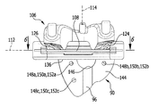
図2に、大腿骨36に接触させた状態に置かれる前の参照ユニット34を概略的に示す。参照ユニットは、マーカ要素42を含む担体要素40を担持する基体38を含む。図2に示すような参照ユニット34において、担体要素40はマーカ要素42が上に配置される多角形の担体プレート44の形態に構成される。これらのマーカ要素は、例えばナビゲーションシステム12のエミッタ50から放射される電磁放射線又は超音波をその表面48が反射する半球体46の形態に構成される。
FIG. 2 schematically shows the
別法として、マーカ要素42は上述のような受動的構成において実施するのでなく、例えば電磁放射線又は超音波を放射する能動的マーカ要素の形態に構成することもできる。
Alternatively, the
マーカ要素42の代わりに、例えば担体要素上のその位置が既知である規定の窪みの形態の規定の参照点を担体要素40上に設けることができる。前記参照点を、例えば、立体カメラ16により検出することのできる少なくとも3つのマーカ要素を含むナビゲーション型触知器具を用いて触知することができる。従って触知器具の空間位置を測定することにより、参照点を空間位置に割り当てることができる。大腿骨36に、少なくとも1つの好ましくは3つの外科用マーカ要素を含む図示しない更なる参照ユニットが固定されている場合、更なる参照ユニットに対する規定の参照点の位置も規定されるのであり、大腿骨36が大腿骨上の担体要素と共に移動する際、更なる参照ユニットの場所及び配向を測定することにより、規定の参照点の位置を、ナビゲーションシステムを介していつでも測定することができる。
Instead of the
マーカ要素42の互いに対する配置は、好ましくはデータ処理機器20のストレージ内に保存される。その際、個々のマーカ要素42の空間位置、故に参照ユニット34の場所及び配向は、概してナビゲーションシステム12を経由して、知られているやり方で測定することができる。
The arrangement of the
図2の参照ユニット34において、基体38と担体要素40とは共に解放不可能に接続される。別法として、基体と担体要素とは一体に構成することができる。
In the
基体38は、平面的な上側52及び底部側54を有する。底部側54は、基体38から離れる方を向くと共に扇状球面であること及び平面状表面であることから外れる、患者特有の骨接触面56の形態に構成される。骨接触面56の輪郭58は、大腿骨36の骨表面60の部分61に対応する。
The
骨表面60に適合する骨接触面56の輪郭58に基づき、基体38を骨表面と正確に嵌合する関係において大腿骨36に接触させた状態に置く可能性が厳密に1つ存在する。大腿骨36上での参照ユニット34のその位置を、図4に説明的に表す。
Based on the
更に参照ユニット34に、固締要素受け62a、62b、及び62cが設けられる。これらの固締要素受けの各々は、参照ユニット34を大腿骨36に固定するための固締要素64を受けるように働く。
Further, the
固締要素受け62a、62b、及び62cは、開口66a、66b、及び66cの形態に、つまり孔68a、68b、及び68cの形態に構成される。孔68a及び68bは上側52に対して交差方向に、特に垂直に延び、骨接触面56を通過する。
The
孔68cは担体プレート44のエリア内に形成され、担体要素40を通過する。担体プレート44の開口66cは、担体要素40の上側70から突出するスリーブ72を経由して幾分延長されるのであり、前記スリーブ72は孔68a及び68bの長手方向軸に対して斜めに延びる長手方向軸を規定する。
A
固締要素64は、骨ねじ山の形態の短い雄ねじ区域78が隣接する先端76を含む骨ピン74の形態に構成される。雄ねじ区域78に隣接しているものは、骨ピン74の全長の半分よりも幾分長い円筒形のシャフト区域80である。
The clamping
骨ピン74の先端76に対向する端部に形成されるものは、図示する骨ピン74の場合では三角の形態に構成される多角形区域82である。骨ピン74により規定される長手方向軸84と平行である多角形区域82の長さは、雄ねじ区域78の長さにほぼ対応する。
What is formed at the end of the
シャフト区域80の外径は孔68a、68b、及び68cの内径に適合するのであり、骨ピン74はそのシャフト区域80が、基本的に遊びのないやり方で開口66a、66b、及び66cを通過することができる。
The outer diameter of the
更に基体38は、医療器具90の第2連結要素88に対応するやり方で上に形成された第1連結要素86を有する。連結要素86及び88は、医療器具90と参照ユニット34とを連結位置において力ロック式及び/又は形状ロック式に連結するための連結装置92を形成する。
In addition, the
第1連結要素86は連結受け94の形態であり、第2連結要素88はこの第1連結要素と協働する対応する連結突起96の形態である。連結受け94は、長手方向軸100を規定する溝の形態に構成され、前記溝は半円形の断面を規定する。連結突起96は、その長手方向軸104が長手方向軸100と平行に走る、半円筒形であるリブ102の形態に構成される。
The
器具90は大腿骨36用の鋸テンプレート106を含む。鋸テンプレート106は、互いに対して垂直に延びる切断面112及び114を規定する2つの鋸スロット108及び110を含む。
器具90は更に、鋸スロット110がそこを通過する突出スロット体120をその前側118で担持する略U形の接触体116を含む。
The
接触体116の後ろ側122でその自由端のエリアにおいて形成されるものは、大腿骨36の骨表面60の一部又は部分132及び134に対応する輪郭128及び130を有する2つの接触体骨接触面124及び126である。
What is formed in the area of its free end on the
接触体骨接触面124及び126の間に形成されるものは、連結位置のときに基体38の平面的な端面138に接触している平面的な止め面136である。
Formed between the contact body bone contact surfaces 124 and 126 is a
第2スロット体140が、この第2スロット体を通過するとともに接触体116の自由脚部間の接続エリア内に配置される鋸スロット108を有する。接触体は、連結突起96がそこから突出する平面的な底部側144を有する連結体142を担持する。実質、連結体142は半環の形状に構成されるのであり、第2スロット体140と共に略半円形の開口146を区切る。
A
底部側144は、連結位置にあるとき基体38の上側52に表面接触している。
The
更に連結体142は、開口150a、150b、及び150cの形態に、つまり孔152a、152b、及び152cの形態に構成される3つの器具固締要素受け148a、148b、及び148cを有する。
Furthermore, the
連結位置のとき、孔152a及び152bの長手方向軸は孔68a及び68bの長手方向軸と一致する。このことにより、参照ユニット34及び器具90は、連結位置にあるとき2つの固締要素64を経由して大腿骨に固定することができる。これを図7〜図9に概略的に表す。
When in the coupled position, the longitudinal axes of
器具90を大腿骨36に付加的に固定できるようにするために、接触体116は上に、接触体骨接触面124及び126を通過する更なる2つの器具固締要素受け148d及び148e設けられる。
In order to allow the
器具固締要素受け148d及び148eも、短いスリーブ154d及び154eにより延長される。器具固締要素受け148d及び148eの長手方向軸は、互いに略平行に延びるとともに、器具固締要素受け148a及び148bの長手方向軸が広がる平面に対して垂直に延びる平面を規定する。最後に指定した平面は更に、切断面112と平行に延びる。更に、器具固締要素受け148d及び148eが広がる平面は切断面114に対して垂直に延びる。
Instrument
患者特有の骨接触面56は、非侵襲的に測定された患者の骨輪郭データに対応する骨接触面輪郭データを規定する。この目的で、特にX線、磁気共鳴、及び/又は超音波画像からの患者の骨輪郭データを活用することができる。
The patient specific
非侵襲的なやり方でこのように測定した患者の骨輪郭データに基づき、患者特有の骨接触面56又は基体38は、例えば鋳造、塑造、切屑生産加工方法、又は3D印刷により製造することができる。従ってこのことは、外科的介入のために、患者の大腿骨36の輪郭に個々に適合する基体38が構成されることを意味する。このようにして大腿骨36上では参照ユニット34が、非侵襲的に測定された患者の骨輪郭データにより一意的に位置決めされる結果となる。
Based on the patient's bone contour data thus measured in a non-invasive manner, the patient-specific
接触体116又は器具90全体は、その接触体骨接触面124及び126が、上で記載したものと同じように構成される。患者特有の接触体骨接触面は、非侵襲的に測定された患者の骨輪郭データに対応する接触体骨接触面輪郭データを規定する。患者のこれらの骨輪郭データも、特にX線、磁気共鳴、及び/又は超音波画像から導くことができる。
The
従って全体的にみて、器具90を大腿骨36上で一意的に位置決めすることに備えることが可能である。更に、連結位置にあるときの参照ユニット34と器具90との間の一意的な空間関係を連結装置92が予め決めておくため、特に非侵襲的に測定された画像データを基にして外科医により予め決めておかれる切断面112及び114は、鋸スロット108及び110を経由して、それぞれの患者に対して個々に一意的に規定される。
Overall, therefore, it is possible to provide for uniquely positioning the
膝関節内プロテーゼの大腿部品を埋込むための大腿骨36の準備のために参照ユニット34及び医療器具90を固定することを以下で説明する。
Fixing the
まず、参照ユニット34はその骨接触面56が骨表面60の部分61にもたらされ、大腿骨36に一意的なやり方で接触しているようにされる。参照ユニット34は、2つの骨ピン74を使用して大腿骨36に予め固定される。この目的で、骨ピン74が固締要素受け62a及び62bを通して挿入される。
First, the
任意で参照ユニット34が大腿骨36に対して回転することを付加的に防止するために、固締要素受け62cを通して更なる骨ピン74を挿入し、骨ピン74を大腿骨36に突っ込むことができる。このことは特に、例えば空間における大腿骨36の場所及び配向を測定するために参照ユニット34が単独で、即ち器具90なしに使用されるべき場合に推奨できる。
Optionally, in order to additionally prevent the
次に、互いに対して平行に大腿骨36から突出して開口66a及び66bを通過する骨ピン74を介して器具90を大腿骨36にもたらすことが可能である。この目的で、予め所定の位置に設定された骨ピン74の多角形区域82に連結体142がもたらされ、その後、これらの骨ピンが孔152a及び152bに通される。
The
大腿骨36及び参照ユニット34に対して器具90が変位することを防止するために、器具固締要素受け148d及び148eを通して更なる2つの骨ピン74が挿入され、これらの骨ピンが大腿骨36内で固着される。
In order to prevent the
器具90を使用して大腿骨36上で鋸カットを実行するために、器具90を除去する必要なしに、任意で大腿骨36から参照ユニット34を除去することができる。この目的で孔152a及び152bを通過する2つの骨ピン74が大腿骨36から除去され、参照ユニット34は大腿骨36と接触体116との間から引き出すことができる。
In order to perform a saw cut on the
別法として、例えば空間におけるその場所及び配向の追跡を継続するために参照ユニット34が大腿骨36上の適所に単独で留まることができるようにして器具90を大腿骨36から除去できるように器具90及び参照ユニット34を構成することも可能である。この目的で、特に鋸カットが一旦入れられたならば、2つの骨ピン148e及び148dを除去した後に、器具90を大腿骨36から及び2つの骨ピン68a及び68bから除去することができる。その際参照ユニット34は、いわゆる「駐車」位置に留まる。
Alternatively, the
任意で記載した順ではないように、器具90と参照ユニットとを共に大腿骨36に接触させた状態に置くことができる。
The
別法として、まず器具90をその接触体骨接触面124及び126が大腿骨36に接触した状態に置いて器具を大腿骨に固定し、その後初めて器具90を参照ユニット34に連結することも可能である。
Alternatively, the
器具90を大腿骨36に良好に固定するために、除去した2つの骨ピン74を再度挿入することができる。別法として又は付加的に、骨ピン74を孔152c内に挿入して大腿骨36内で固着することも可能である。その際この孔の長手方向軸は、孔152a及び152bの長手方向軸に対して斜めの角度で延びる。
In order to better secure the
鋸を用いて大腿骨36上に所望のカットが入れられた後、全ての骨ピン74及び医療器具90は大腿骨から再度除去することができる。
After the desired cut has been made on the
大腿骨36上で更なる鋸カットを実行するために、器具90を図示しない更なる器具に交換することが可能である。
To perform a further saw cut on the
大腿骨36が今や準備されると、図示しない膝関節内プロテーゼの大腿部品を、大腿骨に当てて置き、例えば骨ねじ及び/又は骨セメントを経由してこの大腿骨に適切に取付けることができる。
When the
参照ユニット34及び医療器具90は両方とも、専らポリエーテルエーテルケトン(PEEK)又はポリアミド12(PA12)等の滅菌可能なプラスチック材料から作成することができる。
Both the
任意で、基体38と担体要素40とが互いに解放可能に接続するように構成されることも考えられる。その目的で、一方で基体38上、他方で担体要素40上に配置又は形成される第1及び第2連結要素を含む図示しない連結装置を設けることができる。その際この連結装置により、基体38と担体要素40とを共に、連結装置92と同様のやり方で一時的に接続することができる。特に、このことにより、担体要素40は上にあるマーカ要素42と共に基体38から分離させることが可能になる。従って、例えば、担体要素40は上にあるマーカ要素42と共に複数回使用することができるのであり、基体38はその患者特有の骨接触面56を外科的介入のために患者特有のやり方で製作するだけでよい。従って、付加的に費用を低減することが可能である。
Optionally, it is also conceivable for the
任意で又は別法として、医療用システムは脛骨156に接触させた状態に置かれる前のものを図10に概略的に示す更なる参照ユニット34’を含む。
Optionally or alternatively, the medical system includes a
参照ユニット34’は、マーカ要素42’を含む担体要素40’を担持する基体38’を含む。図10に示すような参照ユニット34’において、担体要素40’は、マーカ要素42’が上に配置される多角形の担体プレート44’の形態に構成される。これらのマーカ要素は、電磁放射線又は超音波をその表面48’が反射する半球体46’の形態に構成される。 The reference unit 34 'includes a substrate 38' that carries a carrier element 40 'that includes a marker element 42'. In a reference unit 34 'as shown in FIG. 10, the carrier element 40' is configured in the form of a polygonal carrier plate 44 'on which the marker element 42' is disposed. These marker elements are configured in the form of a hemisphere 46 'whose surface 48' reflects electromagnetic radiation or ultrasound.
別法としてマーカ要素42’は、上述のような受動的構成において実施するのでなく、例えば電磁放射線又は超音波を放射する能動的マーカ要素の形態に構成することもできる。 Alternatively, the marker element 42 'can be configured in the form of an active marker element that emits electromagnetic radiation or ultrasound, for example, rather than being implemented in a passive configuration as described above.
マーカ要素42’の互いに対する配置は、好ましくはデータ処理機器20のストレージ内に保存される。その際、個々のマーカ要素42’の空間位置、従って参照ユニット34’の場所及び配向は、概してナビゲーションシステム12を経由して、知られているやり方で測定することができる。
The arrangement of the
図10の参照ユニット34’において、基体38’と担体要素40’とは共に解放不可能に接続される。別法として、基体と担体要素とは一体に構成することができる。 In the reference unit 34 'of FIG. 10, both the base body 38' and the carrier element 40 'are connected together in a releasable manner. Alternatively, the substrate and the carrier element can be constructed in one piece.
基体38’は平面的な上側52’及び底部側54’を有する。底部側54’は、基体38’から離れる方を向いて球体の表面の扇形であること及び平面状表面であることから外れる、患者特有の骨接触面56’の形態に構成される。骨接触面56’の輪郭58’は、脛骨156の骨表面60’の部分61’に対応する。
The substrate 38 'has a planar upper side 52' and a bottom side 54 '. The bottom side 54 'is configured in the form of a patient-specific bone contacting surface 56' that faces away from the base 38 'and deviates from the fan-shaped and planar surfaces of the sphere. The
骨表面60’に適合する骨接触面56’の輪郭58’に基づき、基体38’を骨表面と正確に嵌合する関係において脛骨156に接触させた状態に置く可能性が厳密に1つ存在する。脛骨156上での参照ユニット34’のその位置を、図10に説明的に表す。
Based on the contour 58 'of the bone contact surface 56' that conforms to the bone surface 60 ', there is exactly one possibility of placing the substrate 38' in contact with the
更に参照ユニット34’に、固締要素受け62a’、62b’、及び62c’が設けられる。これらの固締要素受けの各々は、参照ユニット34’を脛骨156に固定するための固締要素64を受けるように働く。
Furthermore, the reference unit 34 'is provided with
固締要素受け62a’、62b’、及び62c’は、開口66a’、66b’、及び66c’の形態に、つまり孔68a’、68b’、及び68c’の形態に構成される。孔68a’及び68b’は、上側52’に対して交差方向に、特に垂直に延び、骨接触面56’を通過する。
The clamping
孔68c’は担体プレート44’のエリア内に形成され、担体要素40’を通過する。担体プレート44の開口66c’は、担体要素40’の上側70’から突出するスリーブ72’を経由して幾分延長されるのであり、前記スリーブ72’は、孔68a’及び68b’の長手方向軸に対して斜めに延びる長手方向軸を規定する。
A
参照ユニット34’を脛骨156に固定するために、更なる固締要素64が使用される。これらの固締要素は骨ピン74の形態である。
An
骨ピン74のシャフト区域80の外径も孔68a’、68b’、及び68c’の内径に適合するのであり、骨ピン74はそのシャフト区域80が、基本的に遊びのないやり方で開口66a’、66b’、及び66c’を通過することができる。
The outer diameter of the
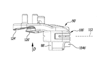
更に基体38’は上に、医療器具90’の第2連結要素88’に対応する第1連結要素86’が形成される。連結要素86’及び88’は、医療器具90’と参照ユニット34’とを連結位置において力ロック式及び/又は形状ロック式に連結するための連結装置92’を形成する。 Furthermore, the base 38 'is formed with a first connecting element 86' corresponding to the second connecting element 88 'of the medical device 90'. The connecting elements 86 'and 88' form a connecting device 92 'for connecting the medical device 90' and the reference unit 34 'in a force-locking and / or shape-locking manner in the connecting position.
第1連結要素86’は連結受け94’の形態であり、第2連結要素88’はこの第1連結要素と協働する対応する連結突起96’の形態である。連結受け94’は長手方向軸100’を規定する溝の形態に構成され、前記溝は半円形の断面を規定する。連結突起96’は、その長手方向軸104’が長手方向軸100’と平行に走る半円筒形であるリブ102’の形態に構成される。 The first coupling element 86 'is in the form of a coupling receiver 94' and the second coupling element 88 'is in the form of a corresponding coupling projection 96' that cooperates with the first coupling element. The coupling receiver 94 'is configured in the form of a groove defining a longitudinal axis 100', said groove defining a semicircular cross section. The connecting projection 96 'is configured in the form of a rib 102' that is semi-cylindrical with its longitudinal axis 104 'running parallel to the longitudinal axis 100'.
器具90’は、脛骨156用の鋸テンプレート106’を含む。鋸テンプレート106’は、切断面112を規定する鋸スロット108’を含む。
The instrument 90 'includes a saw template 106' for the
器具90’は更に、鋸スロット108’がそこを通過する突出スロット体120’を接触体116’の自由脚部間の接続エリアにおいて担持する略U形の接触体116’を含む。 The instrument 90 'further includes a generally U-shaped contact body 116' that carries a protruding slot body 120 'through which the saw slot 108' passes in a connection area between the free legs of the contact body 116 '.
接触体116’の後ろ側122’でその自由端のエリアにおいて形成されるものは、脛骨156の骨表面60’の一部又は部分132’及び134’に対応する輪郭128’及び130’を有する2つの接触体骨接触面124’及び126’である。
What is formed in the area of its free end on the
スロット体120’上に形成されるものは、連結突起96’がそこから突出する平面的な底部側144’を有する連結体142’である。連結体142’は実質、立方形の形状に構成される。
Formed on the slot body 120 'is a coupling body 142' having a planar
底部側144’は連結位置にあるとき、基体38’の上側52’に表面接触している。
When the
更に連結体142’は、開口150a’及び150b’の形態に、つまり孔152a’及び152b’の形態に構成される2つの器具固締要素受け148a’及び148b’を有する。
Furthermore, the
連結位置のとき、孔152a’及び152b’の長手方向軸は孔68a’及び68b’の長手方向軸と一致する。このことにより、参照ユニット34’及び器具90’は、連結位置にあるとき2つの固締要素64を経由して脛骨156に固定することができる。これを図16〜図18に概略的に表す。
When in the coupled position, the longitudinal axes of
器具90’を脛骨156に付加的に固定できるようにするために、接触体116’は上に、接触体骨接触面124’及び126’を通過する更なる2つの器具固締要素受け148c’及び148d’が設けられる。
In order to be able to additionally fix the instrument 90 'to the
スロット体120’上に形成されるものは、具体的にはスリーブ158の開口150e’の形態の更なる器具固締要素受け148e’である。開口150e’は、スリーブ158の孔152e’の形態に構成される。
Formed on the slot body 120 'is a further instrument clamping
器具固締要素受け148a’、148b’、148c’、及び148d’も、短いスリーブ154a’、154b’、154c’、及び154d’により延長される又はその中に形成される。器具固締要素受け148c’及び148d’の長手方向軸は、互いに略平行に延びるとともに、器具固締要素受け148a’及び148b’の長手方向軸が広がる平面に対して垂直に延びる平面を規定する。最後に指定した平面は更に、切断面112’と平行に延びる。
Instrument
患者特有の骨接触面56’は、非侵襲的に測定された患者の骨輪郭データに対応する骨接触面輪郭データを規定する。この目的で、特にX線、磁気共鳴、及び/又は超音波画像からの患者の骨輪郭データを活用することができる。 The patient specific bone contact surface 56 'defines bone contact surface contour data corresponding to the bone contour data of the patient measured non-invasively. For this purpose, in particular the patient's bone contour data from X-ray, magnetic resonance and / or ultrasound images can be exploited.
非侵襲的なやり方でこのように測定した患者の骨輪郭データに基づき、患者特有の骨接触面56’又は基体38’は、例えば、鋳造、切屑生産加工方法、又は3D印刷により製造することができる。従ってこのことは、外科的介入のために、患者の脛骨156の輪郭に個々に適合する基体38’が構成されることを意味する。従って、脛骨156上では参照ユニット34’が、非侵襲的に測定された患者の骨輪郭データにより一意的に位置決めされる結果となる。
Based on the patient's bone contour data thus measured in a non-invasive manner, the patient-specific bone contact surface 56 'or substrate 38' can be manufactured, for example, by casting, chip production processing methods, or 3D printing. it can. This therefore means that a base body 38 'is constructed that is individually adapted to the contour of the patient's
接触体116’又は器具90’全体も、その接触体骨接触面124’及び126’が、上で記載したものと同じように構成される。患者特有の接触体骨接触面は、非侵襲的に測定した患者の骨輪郭データに対応する接触体骨接触面輪郭データを規定する。患者のこれらの骨輪郭データも、特にX線、磁気共鳴、及び/又は超音波画像から導くことができる。 The contact body 116 'or the entire instrument 90' is also configured with its contact body bone contact surfaces 124 'and 126' in the same manner as described above. The patient-specific contact body bone contact surface defines contact body bone contact surface contour data corresponding to the bone contour data of the patient measured non-invasively. These bone contour data of the patient can also be derived from X-rays, magnetic resonance and / or ultrasound images, among others.
従って、全体的にみて、器具90’を脛骨156上で一意的に位置決めすることに備えることが可能である。更に連結位置にあるときの参照ユニット34’と器具90’との間の一意的な空間関係を連結装置92’が予め決めておくため、特に非侵襲的に測定された画像データを基にして外科医により予め決めておかれる切断面112’は、鋸スロット108’を経由してそれぞれの患者に対して個々に一意的に規定される。
Thus, overall, it is possible to provide for uniquely positioning the
膝関節内プロテーゼの脛骨部品を埋込むための脛骨156の準備のために、参照ユニット34’及び医療器具90’を固定することを以下で説明する。
The fixation of the reference unit 34 'and the medical device 90' for the preparation of the
まず参照ユニット34’は、その骨接触面56’が骨表面60’の部分61’にもたらされ、脛骨156に一意的なやり方で接触しているようにされる。参照ユニット34’は、2つの骨ピン74を使用して脛骨156に予め固定される。この目的で、骨ピン74が固締要素受け62a’及び62b’を通して挿入される。
First, the
任意で参照ユニット34’が脛骨156に対して回転することを付加的に防止するために、固締要素受け62c’を通して更なる骨ピン74を挿入し、この骨ピンを脛骨156に突っ込むことができる。このことは特に、例えば空間における脛骨156の場所及び配向を測定するために参照ユニット34’が単独で、即ち器具90’なしに使用されるべき場合に推奨できる。
Optionally, in order to additionally prevent the
次に、互いに対して平行に脛骨156から突出して開口66a’及び66b’を通過する骨ピン74を介して器具90’を脛骨156にもたらすことが可能である。この目的で、予め所定の位置に設定された骨ピン74の多角形区域82に連結体142’がもたらされ、その後、これらの骨ピンが孔152a’及び152b’に通される。
The instrument 90 'can then be brought into the
脛骨156及び参照ユニット34’に対して器具90’が変位することを防止するために、器具固締要素受け148c’及び148d’を通して更なる2つの骨ピン74が挿入され、これらの骨ピンが脛骨156内で固着される。
Two additional bone pins 74 are inserted through the instrument locking
器具90’を使用して脛骨156上で鋸カットを実行するために、器具90’を除去する必要なしに、任意で脛骨156から参照ユニット34’を除去することができる。この目的で、孔152a’及び152b’を通過する2つの骨ピン74が脛骨156から除去され、参照ユニット34’は脛骨156と接触体116’との間から引き出すことができる。
In order to perform a saw cut on the
別法として、例えば空間におけるその場所及び配向の追跡を継続するために参照ユニット34’が脛骨156上の適所に単独で留まることができるようにして器具90’を脛骨156から除去できるように器具90’及び参照ユニット34’を構成することも可能である。この目的で特に、鋸カットが一旦入れられたならば、骨ピン148e’、148c’、及び148d’を除去した後に、器具90’を脛骨156から及び2つの骨ピン148a’及び148b’から除去することができる。その際参照ユニット34’は、いわゆる「駐車」位置に留まる。
Alternatively, the instrument 90 'can be removed from the
任意で記載した順ではないように、器具90’と参照ユニットとを共に脛骨156に接触させた状態に置くことができる。
The instrument 90 'and the reference unit can both be in contact with the
別法として、まず器具90’をその接触体骨接触面124’及び126’が脛骨156に接触した状態に置いて器具を脛骨に固定し、その後初めて器具90’を参照ユニット34’に連結することも可能である。
Alternatively, the instrument 90 'is first placed in contact with its bone contact surfaces 124' and 126 'in contact with the
器具90’を脛骨156に良好に固定するために、除去した2つの骨ピン74を再度挿入することができる。別法として又は付加的に、骨ピン74を、孔152e’を通して挿入して脛骨156内で固着することも可能である。その際孔152e’の長手方向軸は、孔152a’及び152b’の長手方向軸に対して斜めの角度で延びる。
In order to better secure the instrument 90 'to the
鋸を用いて脛骨156上に所望のカットが入れられた後、全ての骨ピン74及び医療器具90’は脛骨156から再度除去することができる。
After the desired cut has been made on the
脛骨156上で更なる鋸カットを実行するために、器具90’を図示しない更なる器具に交換することが可能である。
In order to perform further saw cuts on the
脛骨156が今や準備されると、図示しない膝関節内プロテーゼの脛骨部品を脛骨に当てて置き、例えば骨ねじ及び/又は骨セメントを経由してこの脛骨に適切に取付けることができる。
Once the
参照ユニット34’及び医療器具90’は両方とも、専らポリエーテルエーテルケトン(PEEK)等の滅菌可能なプラスチック材料から作成することができる。 Both the reference unit 34 'and the medical device 90' can be made entirely from a sterilizable plastic material such as polyetheretherketone (PEEK).
任意で、基体38’と担体要素40’とが、互いに解放可能に接続するように構成されることも考えられる。その目的で、一方で基体38’上、他方で担体要素40’上に配置又は形成される第1及び第2連結要素を含む図示しない連結装置を設けることができる。その際この連結装置により、基体38’と担体要素40’とを共に、連結装置92’と同様のやり方で一時的に接続することができる。特にこのことにより、担体要素40’は上にあるマーカ要素42’と共に基体38’から分離させることが可能になる。従って、例えば担体要素40’は上にあるマーカ要素42と共に複数回使用することができるのであり、基体38’はその患者特有の骨接触面56’により外科的介入のために患者特有のやり方で製作するだけでよい。従って、付加的に費用を低減することが可能である。
Optionally, it is contemplated that the base body 38 'and the carrier element 40' are configured to releasably connect to each other. For that purpose, it is possible to provide a connection device (not shown) including first and second connection elements arranged or formed on the base body 38 'on the one hand and on the carrier element 40' on the other hand. In this case, the coupling device allows the base body 38 'and the carrier element 40' to be temporarily connected together in the same manner as the coupling device 92 '. In particular, this allows the carrier element 40 'to be separated from the substrate 38' together with the overlying marker element 42 '. Thus, for example, the carrier element 40 'can be used multiple times with the
10 医療用システム
12 ナビゲーションシステム
14 受信ユニット
16 立体カメラ
18 検出器
20 データ処理機器
22 コンピュータ
24 モニタ
26 入力装置
28 入力装置
30 キーボード
32 マウス
34,34’ 参照ユニット
36 大腿骨
38,38’ 基体
40,40’ 担体要素
42,42’ マーカ要素
44,44’ 担体プレート
46,46’ 半球体
48,48’ 表面
50 エミッタ
52,52’ 上側
54,54’ 底部側
56,56’ 骨接触面
58,58’ 輪郭
60,60’ 骨表面
61,61’ 部分
62a,62b,62c,62a’,62b’,62c’ 固締要素受け
64 固締要素
66a,66b,66c,66a’,66b’,66c’ 開口
68a,68b,68c,68a’,68b’,68c’ 孔
70,70’ 上側
72,72’ スリーブ
74 骨ピン
76 先端
78 雄ねじ区域
80 シャフト区域
82 多角形区域
84 長手方向軸
86,86’ 第1連結要素
88,88’ 第2連結要素
90,90’ 医療器具
92,92’ 連結装置
94,94’ 連結受け
96,96’ 連結突起
98,98’ 溝
100,100’ 長手方向軸
102,102’ リブ
104,104’ 長手方向軸
106,106’ 鋸テンプレート
108,108’ 鋸スロット
110 鋸スロット
112,112’ 切断面
114 切断面
116,116’ 接触体
118,118’ 前側
120,120’ 第1スロット体
122,122’ 後ろ側
124,124’ 接触体骨接触面
126,126’ 接触体骨接触面
128,128’ 輪郭
130,130’ 輪郭
132,132’ 部分
134,134’ 部分
136 接触面
138 端面
140 第2スロット体
142,142’ 連結体
144,144’ 底部側
146 開口
148a,148b,148c,148d,148a’,148b’,148c’,148d’ 器具固締要素受け
150a,150b,150c,150d,150a’,150b’,150c’,150d 開口
152a,152b,152c,152d,152a’,152b’,152c’,152’ 孔
154a,154b,154c,154d,154a’,154b’ 154c’,154d’ スリーブ
156 脛骨
158 スリーブ
DESCRIPTION OF SYMBOLS 10 Medical system 12 Navigation system 14 Reception unit 16 Stereo camera 18 Detector 20 Data processing equipment 22 Computer 24 Monitor 26 Input device 28 Input device 30 Keyboard 32 Mouse 34, 34 'Reference unit 36 Femur 38, 38' Base 40, 40 'carrier element 42, 42' marker element 44, 44 'carrier plate 46, 46' hemisphere 48, 48 'surface 50 emitter 52, 52' upper side 54, 54 'bottom side 56, 56' bone contact surface 58, 58 'Contour 60, 60' Bone surface 61, 61 'Portions 62a, 62b, 62c, 62a', 62b ', 62c' Clamping element receiver 64 Clamping elements 66a, 66b, 66c, 66a ', 66b', 66c 'Opening 68a, 68b, 68c, 68a ′, 68b ′, 68c ′ Holes 70, 70 ′ Upper 72, 72 ′ Sleeve 74 Bone pin 7 6 Tip 78 Male thread area 80 Shaft area 82 Polygonal area 84 Longitudinal axis 86, 86 'First connecting element 88, 88' Second connecting element 90, 90 'Medical instrument 92, 92' Connecting device 94, 94 'Connecting receptacle 96, 96 'connecting projection 98, 98' groove 100, 100 'longitudinal axis 102, 102' rib 104, 104 'longitudinal axis 106, 106' saw template 108, 108 'saw slot 110 saw slot 112, 112' cutting Surface 114 Cutting surface 116, 116 ′ Contact body 118, 118 ′ Front side 120, 120 ′ First slot body 122, 122 ′ Rear side 124, 124 ′ Contact body bone contact surface 126, 126 ′ Contact body bone contact surface 128, 128 'Contour 130, 130' Contour 132, 132 'Portion 134, 134' Portion 136 Contact surface 138 End surface 140 Second slot body 142, 142 ' Connector 144, 144 'Bottom side 146 Opening 148a, 148b, 148c, 148d, 148a', 148b ', 148c', 148d 'Instrument fastening element receiver 150a, 150b, 150c, 150d, 150a', 150b ', 150c' , 150d Openings 152a, 152b, 152c, 152d, 152a ′, 152b ′, 152c ′, 152 ′ Holes 154a, 154b, 154c, 154d, 154a ′, 154b ′ 154c ′, 154d ′ Sleeve 156 Tibial 158 Sleeve
Claims (27)
その空間位置が、外科用ナビゲーションシステム(12)を使用して検出可能な少なくとも1つの医療用参照ユニット(34;34’)を含み、
少なくとも1つの医療用参照ユニット(34;34’)が、担体要素(40;40’)上に配置又は形成されるとともに前記外科用ナビゲーションシステム(12)の検出装置(16)を使用して検出可能である少なくとも1つの外科用マーカ要素(42;42’)を含み、
少なくとも1つの医療用参照ユニット(34;34’)が、前記担体要素(40;40’)を担持する基体(38;38’)を含む、医療用システムにおいて、
前記基体(38;38’)が、前記基体(38;38’)から離れる方を向くとともに、球体の表面の扇形であること及び平面状表面であることから外れる少なくとも1つの患者特有の骨接触面(56;56’)を含み、
前記少なくとも1つの骨接触面(56;56’)が、前記患者の骨表面(60;60’)に対応するやり方で形成されること、を特徴とする医療用システム。 In particular, a medical system (10) for implanting a knee joint prosthesis,
The spatial position includes at least one medical reference unit (34; 34 ') that is detectable using the surgical navigation system (12);
At least one medical reference unit (34; 34 ') is arranged or formed on the carrier element (40; 40') and is detected using the detection device (16) of the surgical navigation system (12) Including at least one surgical marker element (42; 42 '),
In a medical system, wherein at least one medical reference unit (34; 34 ') comprises a substrate (38; 38') carrying said carrier element (40; 40 ')
At least one patient-specific bone contact where the substrate (38; 38 ') faces away from the substrate (38; 38') and deviates from being a sectoral and planar surface of the sphere. A surface (56; 56 '),
The medical system, wherein the at least one bone contacting surface (56; 56 ') is formed in a manner corresponding to the bone surface (60; 60') of the patient.
前記少なくとも1つの医療器具(90;90’)が、接触体(116;116’)を含み、
接触体(116;116’)が、前記接触体から離れる方を向くとともに、球体の表面の扇形であること及び平面状表面であることから外れる少なくとも1つの患者特有の接触体骨接触面(124、126;124’、126’)を含み、
前記少なくとも1つの患者特有の接触体骨接触面(124、126;124’、126’)が、前記患者の骨表面に対応するやり方で形成されること、を特徴とする医療用システム。 The medical system according to any one of claims 10 to 15,
Said at least one medical device (90; 90 ') comprises a contact (116; 116');
The contact body (116; 116 ') faces away from the contact body and is at least one patient-specific contact body bone contact surface (124) that deviates from the fan-shaped and planar surfaces of the sphere. 126; 124 ′, 126 ′),
The medical system, wherein the at least one patient-specific contact body bone contact surface (124, 126; 124 ', 126') is formed in a manner corresponding to the patient's bone surface.
Applications Claiming Priority (3)
| Application Number | Priority Date | Filing Date | Title |
|---|---|---|---|
| DE102014107481.5 | 2014-05-27 | ||
| DE102014107481.5A DE102014107481A1 (en) | 2014-05-27 | 2014-05-27 | Medical system |
| PCT/EP2015/061621 WO2015181188A1 (en) | 2014-05-27 | 2015-05-27 | Medical system |
Publications (3)
| Publication Number | Publication Date |
|---|---|
| JP2017516554A true JP2017516554A (en) | 2017-06-22 |
| JP2017516554A5 JP2017516554A5 (en) | 2018-07-05 |
| JP6591452B2 JP6591452B2 (en) | 2019-10-16 |
Family
ID=53433162
Family Applications (1)
| Application Number | Title | Priority Date | Filing Date |
|---|---|---|---|
| JP2016569628A Active JP6591452B2 (en) | 2014-05-27 | 2015-05-27 | Medical system |
Country Status (6)
| Country | Link |
|---|---|
| US (1) | US10675096B2 (en) |
| EP (1) | EP3151774B1 (en) |
| JP (1) | JP6591452B2 (en) |
| CN (1) | CN106413591B (en) |
| DE (1) | DE102014107481A1 (en) |
| WO (1) | WO2015181188A1 (en) |
Cited By (1)
| Publication number | Priority date | Publication date | Assignee | Title |
|---|---|---|---|---|
| JP2022539666A (en) * | 2019-06-06 | 2022-09-13 | サントザリスメンディ グルーポ デ インベスティガシオン エセ.エレ | Instrument Alignment System Used in Total Knee Arthroplasty |
Families Citing this family (20)
| Publication number | Priority date | Publication date | Assignee | Title |
|---|---|---|---|---|
| EP2558011A4 (en) * | 2010-04-14 | 2017-11-15 | Smith & Nephew, Inc. | Systems and methods for patient- based computer assisted surgical procedures |
| WO2018213835A1 (en) * | 2017-05-19 | 2018-11-22 | Smith & Nephew, Inc. | Cut guide system |
| AU2019269713A1 (en) * | 2018-05-18 | 2020-11-26 | Smith & Nephew Asia Pacific Pte Limited | System and method for tracking resection planes |
| US10856891B2 (en) * | 2018-05-29 | 2020-12-08 | DePuy Synthes Products, Inc. | Customized patient-specific orthopaedic surgical instruments |
| CN109009473B (en) * | 2018-07-14 | 2021-04-06 | 杭州三坛医疗科技有限公司 | Vertebral column trauma positioning system and positioning method thereof |
| CN109953828B (en) * | 2019-05-07 | 2020-06-23 | 北京和华瑞博医疗科技有限公司 | Reference frame coordinate system retrieving method and reference frame coordinate system retrieving device |
| US20210145458A1 (en) * | 2019-11-19 | 2021-05-20 | Thomas Paszicsnyek | Three-dimensional orientation system and method for orthopedic surgery |
| CN111388087B (en) * | 2020-04-26 | 2026-01-02 | 深圳市鑫君特智能医疗器械有限公司 | Surgical navigation system and computer and storage medium for executing surgical navigation methods |
| CN111388088B (en) * | 2020-04-26 | 2024-03-29 | 深圳市鑫君特智能医疗器械有限公司 | Surgical guide, three-dimensional model, manufacturing and constructing method, computer and storage medium |
| US11864959B2 (en) * | 2020-07-20 | 2024-01-09 | Orthosoft Ulc | Surgical guides |
| ES2895389A1 (en) * | 2020-08-21 | 2022-02-21 | Pedreno Conrado Miguel Bano | Method implemented by computer planning and surgical navigation for osteosynthesis surgeries, corrective osteotomies and tumor surgery with navigable measurement guides, navigated polyxial instruments, wedges and plates of custom osteosynthesis (Machine-translation by Google Translate, not legally binding) |
| WO2022150284A1 (en) | 2021-01-06 | 2022-07-14 | Mako Surgical Corp. | Tracker for a navigation system |
| US20220296390A1 (en) * | 2021-03-16 | 2022-09-22 | Medfit International Ag | System and method for dynamic hip and shoulder joint balancing using functional stability measurements |
| US20220370081A1 (en) * | 2021-05-20 | 2022-11-24 | Wright Medical Technology, Inc. | Surgical guides and methods of manufacture and use |
| US12467489B2 (en) | 2022-03-17 | 2025-11-11 | Mako Surgical Corp. | Techniques for securing together components of one or more surgical carts |
| US12465376B2 (en) * | 2022-03-21 | 2025-11-11 | Microport Orthopedics Holdings Inc. | Medial biased patient-specific instrumentation and related methods |
| CN114948076A (en) * | 2022-05-24 | 2022-08-30 | 苏州铸正机器人有限公司 | Tibial tunnel reconstruction guider, positioning method and system and arthroscope |
| AU2024310381A1 (en) * | 2023-06-26 | 2026-02-12 | Stryker European Operations Limited | Sawblade position identification process for mixed reality surgical navigation |
| USD1117755S1 (en) | 2023-08-18 | 2026-03-10 | Mako Surgical Corp. | Surgical tracker |
| WO2025195657A1 (en) * | 2024-03-21 | 2025-09-25 | Smith & Nephew, Inc. | Systems, devices and methods for navigated bone resection |
Citations (7)
| Publication number | Priority date | Publication date | Assignee | Title |
|---|---|---|---|---|
| JP2001507614A (en) * | 1997-10-28 | 2001-06-12 | カール−ツアイス−スチフツング | Bone segment navigation system |
| US20060195111A1 (en) * | 2005-01-25 | 2006-08-31 | Orthosoft Inc. | Universal positioning block assembly |
| JP2009530004A (en) * | 2006-03-23 | 2009-08-27 | インペリアル イノベーションズ リミテッド | Anterior cruciate ligament reconstruction |
| JP2010110635A (en) * | 2002-08-23 | 2010-05-20 | Orthosoft Inc | Surgical universal positioning block and tool guide |
| WO2012169642A1 (en) * | 2011-06-06 | 2012-12-13 | 株式会社大野興業 | Method for manufacturing registration template |
| JP2013523415A (en) * | 2010-04-14 | 2013-06-17 | スミス アンド ネフュー インコーポレーテッド | System and method for patient-assisted computer-assisted surgical procedure |
| US20140039520A1 (en) * | 2006-06-16 | 2014-02-06 | Hani Haider | Method and apparatus for computer aided surgery |
Family Cites Families (14)
| Publication number | Priority date | Publication date | Assignee | Title |
|---|---|---|---|---|
| DE4219939C2 (en) | 1992-06-18 | 1995-10-19 | Klaus Dipl Ing Radermacher | Device for aligning, positioning and guiding machining tools, machining or measuring devices for machining a bony structure and method for producing this device |
| US6327491B1 (en) * | 1998-07-06 | 2001-12-04 | Neutar, Llc | Customized surgical fixture |
| US20050113846A1 (en) * | 2001-02-27 | 2005-05-26 | Carson Christopher P. | Surgical navigation systems and processes for unicompartmental knee arthroplasty |
| FR2884407B1 (en) * | 2005-04-13 | 2007-05-25 | Tornier Sas | SURGICAL DEVICE FOR IMPLANTATION OF A PARTIAL OR TOTAL KNEE PROSTHESIS |
| US20070066917A1 (en) * | 2005-09-20 | 2007-03-22 | Hodorek Robert A | Method for simulating prosthetic implant selection and placement |
| US20070078678A1 (en) * | 2005-09-30 | 2007-04-05 | Disilvestro Mark R | System and method for performing a computer assisted orthopaedic surgical procedure |
| EP1958575B1 (en) | 2007-02-13 | 2014-08-13 | Brainlab AG | Device or system for positioning or preparing the positioning of a medical operating instrument, especially an incision block or a cutting block or a ligament balancing device |
| US20080319491A1 (en) * | 2007-06-19 | 2008-12-25 | Ryan Schoenefeld | Patient-matched surgical component and methods of use |
| DE102010060914A1 (en) | 2010-11-30 | 2012-05-31 | Aesculap Ag | Surgical marker element for surgical correlation unit of surgical navigation system, has luminescent material that is excited from low energy state to high energy state by producing electromagnetic radiation or electron bombardment |
| US8668700B2 (en) * | 2011-04-29 | 2014-03-11 | Biomet Manufacturing, Llc | Patient-specific convertible guides |
| EP2863820B1 (en) * | 2012-06-20 | 2020-10-28 | Intellijoint Surgical Inc. | Method of manufacturing a system for guided surgery |
| CN104461718B (en) | 2013-09-23 | 2017-12-12 | 腾讯科技(深圳)有限公司 | The picture playing method and client of game application |
| US9463030B2 (en) * | 2013-09-25 | 2016-10-11 | Biomet Manufacturing, Llc | Positioning multiple implants with respect to single coordinate system |
| US11006969B2 (en) * | 2017-06-04 | 2021-05-18 | Felasfa Wodajo | Patient-specific cutting guide |
-
2014
- 2014-05-27 DE DE102014107481.5A patent/DE102014107481A1/en not_active Withdrawn
-
2015
- 2015-05-27 WO PCT/EP2015/061621 patent/WO2015181188A1/en not_active Ceased
- 2015-05-27 CN CN201580028237.3A patent/CN106413591B/en active Active
- 2015-05-27 JP JP2016569628A patent/JP6591452B2/en active Active
- 2015-05-27 EP EP15729763.1A patent/EP3151774B1/en active Active
-
2016
- 2016-11-22 US US15/358,799 patent/US10675096B2/en active Active
Patent Citations (7)
| Publication number | Priority date | Publication date | Assignee | Title |
|---|---|---|---|---|
| JP2001507614A (en) * | 1997-10-28 | 2001-06-12 | カール−ツアイス−スチフツング | Bone segment navigation system |
| JP2010110635A (en) * | 2002-08-23 | 2010-05-20 | Orthosoft Inc | Surgical universal positioning block and tool guide |
| US20060195111A1 (en) * | 2005-01-25 | 2006-08-31 | Orthosoft Inc. | Universal positioning block assembly |
| JP2009530004A (en) * | 2006-03-23 | 2009-08-27 | インペリアル イノベーションズ リミテッド | Anterior cruciate ligament reconstruction |
| US20140039520A1 (en) * | 2006-06-16 | 2014-02-06 | Hani Haider | Method and apparatus for computer aided surgery |
| JP2013523415A (en) * | 2010-04-14 | 2013-06-17 | スミス アンド ネフュー インコーポレーテッド | System and method for patient-assisted computer-assisted surgical procedure |
| WO2012169642A1 (en) * | 2011-06-06 | 2012-12-13 | 株式会社大野興業 | Method for manufacturing registration template |
Cited By (1)
| Publication number | Priority date | Publication date | Assignee | Title |
|---|---|---|---|---|
| JP2022539666A (en) * | 2019-06-06 | 2022-09-13 | サントザリスメンディ グルーポ デ インベスティガシオン エセ.エレ | Instrument Alignment System Used in Total Knee Arthroplasty |
Also Published As
| Publication number | Publication date |
|---|---|
| EP3151774B1 (en) | 2018-07-11 |
| WO2015181188A1 (en) | 2015-12-03 |
| US10675096B2 (en) | 2020-06-09 |
| CN106413591B (en) | 2019-06-04 |
| DE102014107481A1 (en) | 2015-12-03 |
| EP3151774A1 (en) | 2017-04-12 |
| JP6591452B2 (en) | 2019-10-16 |
| US20170071677A1 (en) | 2017-03-16 |
| CN106413591A (en) | 2017-02-15 |
Similar Documents
| Publication | Publication Date | Title |
|---|---|---|
| JP6591452B2 (en) | Medical system | |
| US12433694B2 (en) | Hip replacement navigation system and method | |
| JP6643410B2 (en) | Method and apparatus for determining the positioning of an acetabular component | |
| US11298189B2 (en) | Prosthesis guide comprising patient-matched features | |
| US20140257304A1 (en) | Patient-Specific Glenoid Guide With a Reusable Guide Holder | |
| CN103347458B (en) | For monitoring the equipment of the spin orientation of osteocomma | |
| JP2005013737A (en) | Device usable together with computer support navigation system, device usable to make instrument usable together with computer support navigation system and method for making instrument having first predetermined geometry to be registered in computer support system | |
| JP2014131724A (en) | Alignment guide with shape for intra-operation fluoroscopic examination | |
| JP2017516554A5 (en) | ||
| JP2019518512A (en) | Patient-specific prosthesis alignment | |
| US9463030B2 (en) | Positioning multiple implants with respect to single coordinate system | |
| WO2018095499A1 (en) | A patient specific template and method for partial knee replacement | |
| CA2496351A1 (en) | Navigated surgical sizing guide | |
| US20170105740A1 (en) | 4-in-1 femoral finishing cutting jig | |
| US11185424B2 (en) | Alignment guide for acetabular implant surgery and methods for use | |
| KR101362252B1 (en) | Patient-specific registration guide and method using the same | |
| KR101502529B1 (en) | Apparatus for measuring femoral stem anteversion |
Legal Events
| Date | Code | Title | Description |
|---|---|---|---|
| A521 | Request for written amendment filed |
Free format text: JAPANESE INTERMEDIATE CODE: A821 Effective date: 20170207 |
|
| RD01 | Notification of change of attorney |
Free format text: JAPANESE INTERMEDIATE CODE: A7426 Effective date: 20170207 |
|
| A521 | Request for written amendment filed |
Free format text: JAPANESE INTERMEDIATE CODE: A523 Effective date: 20180523 |
|
| A621 | Written request for application examination |
Free format text: JAPANESE INTERMEDIATE CODE: A621 Effective date: 20180523 |
|
| A977 | Report on retrieval |
Free format text: JAPANESE INTERMEDIATE CODE: A971007 Effective date: 20190306 |
|
| A131 | Notification of reasons for refusal |
Free format text: JAPANESE INTERMEDIATE CODE: A131 Effective date: 20190507 |
|
| A521 | Request for written amendment filed |
Free format text: JAPANESE INTERMEDIATE CODE: A523 Effective date: 20190807 |
|
| TRDD | Decision of grant or rejection written | ||
| A01 | Written decision to grant a patent or to grant a registration (utility model) |
Free format text: JAPANESE INTERMEDIATE CODE: A01 Effective date: 20190903 |
|
| A61 | First payment of annual fees (during grant procedure) |
Free format text: JAPANESE INTERMEDIATE CODE: A61 Effective date: 20190918 |
|
| R150 | Certificate of patent or registration of utility model |
Ref document number: 6591452 Country of ref document: JP Free format text: JAPANESE INTERMEDIATE CODE: R150 |
|
| R250 | Receipt of annual fees |
Free format text: JAPANESE INTERMEDIATE CODE: R250 |
|
| R250 | Receipt of annual fees |
Free format text: JAPANESE INTERMEDIATE CODE: R250 |
|
| R250 | Receipt of annual fees |
Free format text: JAPANESE INTERMEDIATE CODE: R250 |
|
| R250 | Receipt of annual fees |
Free format text: JAPANESE INTERMEDIATE CODE: R250 |