JP2017514752A - Vehicle suspension - Google Patents
Vehicle suspension Download PDFInfo
- Publication number
- JP2017514752A JP2017514752A JP2016566974A JP2016566974A JP2017514752A JP 2017514752 A JP2017514752 A JP 2017514752A JP 2016566974 A JP2016566974 A JP 2016566974A JP 2016566974 A JP2016566974 A JP 2016566974A JP 2017514752 A JP2017514752 A JP 2017514752A
- Authority
- JP
- Japan
- Prior art keywords
- vehicle suspension
- chassis
- support arm
- suspension according
- vehicle
- Prior art date
- Legal status (The legal status is an assumption and is not a legal conclusion. Google has not performed a legal analysis and makes no representation as to the accuracy of the status listed.)
- Granted
Links
- 239000000725 suspension Substances 0.000 title claims abstract description 59
- 239000006096 absorbing agent Substances 0.000 claims description 2
- 230000035939 shock Effects 0.000 claims description 2
- 230000007246 mechanism Effects 0.000 description 28
- 230000000694 effects Effects 0.000 description 6
- 230000006835 compression Effects 0.000 description 2
- 238000007906 compression Methods 0.000 description 2
- 238000004519 manufacturing process Methods 0.000 description 2
- 230000003014 reinforcing effect Effects 0.000 description 2
- 238000005452 bending Methods 0.000 description 1
- 230000009286 beneficial effect Effects 0.000 description 1
- 230000005540 biological transmission Effects 0.000 description 1
- 238000013016 damping Methods 0.000 description 1
- 230000007613 environmental effect Effects 0.000 description 1
- 230000002349 favourable effect Effects 0.000 description 1
- 239000000446 fuel Substances 0.000 description 1
- 239000000463 material Substances 0.000 description 1
- 239000002184 metal Substances 0.000 description 1
- 238000012986 modification Methods 0.000 description 1
- 230000004048 modification Effects 0.000 description 1
- 239000002994 raw material Substances 0.000 description 1
- 230000001105 regulatory effect Effects 0.000 description 1
- 238000000926 separation method Methods 0.000 description 1
Images


Classifications
-
- B—PERFORMING OPERATIONS; TRANSPORTING
- B60—VEHICLES IN GENERAL
- B60G—VEHICLE SUSPENSION ARRANGEMENTS
- B60G3/00—Resilient suspensions for a single wheel
- B60G3/18—Resilient suspensions for a single wheel with two or more pivoted arms, e.g. parallelogram
- B60G3/20—Resilient suspensions for a single wheel with two or more pivoted arms, e.g. parallelogram all arms being rigid
- B60G3/202—Resilient suspensions for a single wheel with two or more pivoted arms, e.g. parallelogram all arms being rigid having one longitudinal arm and two parallel transversal arms, e.g. dual-link type strut suspension
-
- B—PERFORMING OPERATIONS; TRANSPORTING
- B60—VEHICLES IN GENERAL
- B60G—VEHICLE SUSPENSION ARRANGEMENTS
- B60G3/00—Resilient suspensions for a single wheel
- B60G3/18—Resilient suspensions for a single wheel with two or more pivoted arms, e.g. parallelogram
- B60G3/20—Resilient suspensions for a single wheel with two or more pivoted arms, e.g. parallelogram all arms being rigid
-
- B—PERFORMING OPERATIONS; TRANSPORTING
- B60—VEHICLES IN GENERAL
- B60G—VEHICLE SUSPENSION ARRANGEMENTS
- B60G15/00—Resilient suspensions characterised by arrangement, location or type of combined spring and vibration damper, e.g. telescopic type
- B60G15/02—Resilient suspensions characterised by arrangement, location or type of combined spring and vibration damper, e.g. telescopic type having mechanical spring
- B60G15/06—Resilient suspensions characterised by arrangement, location or type of combined spring and vibration damper, e.g. telescopic type having mechanical spring and fluid damper
- B60G15/067—Resilient suspensions characterised by arrangement, location or type of combined spring and vibration damper, e.g. telescopic type having mechanical spring and fluid damper characterised by the mounting on the vehicle body or chassis of the spring and damper unit
- B60G15/068—Resilient suspensions characterised by arrangement, location or type of combined spring and vibration damper, e.g. telescopic type having mechanical spring and fluid damper characterised by the mounting on the vehicle body or chassis of the spring and damper unit specially adapted for MacPherson strut-type suspension
-
- B—PERFORMING OPERATIONS; TRANSPORTING
- B60—VEHICLES IN GENERAL
- B60G—VEHICLE SUSPENSION ARRANGEMENTS
- B60G3/00—Resilient suspensions for a single wheel
- B60G3/18—Resilient suspensions for a single wheel with two or more pivoted arms, e.g. parallelogram
- B60G3/20—Resilient suspensions for a single wheel with two or more pivoted arms, e.g. parallelogram all arms being rigid
- B60G3/26—Means for maintaining substantially-constant wheel camber during suspension movement ; Means for controlling the variation of the wheel position during suspension movement
- B60G3/265—Means for maintaining substantially-constant wheel camber during suspension movement ; Means for controlling the variation of the wheel position during suspension movement with a strut cylinder contributing to the suspension geometry by being linked to the wheel support via an articulation
-
- B—PERFORMING OPERATIONS; TRANSPORTING
- B60—VEHICLES IN GENERAL
- B60G—VEHICLE SUSPENSION ARRANGEMENTS
- B60G7/00—Pivoted suspension arms; Accessories thereof
- B60G7/001—Suspension arms, e.g. constructional features
-
- B—PERFORMING OPERATIONS; TRANSPORTING
- B60—VEHICLES IN GENERAL
- B60G—VEHICLE SUSPENSION ARRANGEMENTS
- B60G2200/00—Indexing codes relating to suspension types
- B60G2200/10—Independent suspensions
- B60G2200/14—Independent suspensions with lateral arms
-
- B—PERFORMING OPERATIONS; TRANSPORTING
- B60—VEHICLES IN GENERAL
- B60G—VEHICLE SUSPENSION ARRANGEMENTS
- B60G2200/00—Indexing codes relating to suspension types
- B60G2200/10—Independent suspensions
- B60G2200/14—Independent suspensions with lateral arms
- B60G2200/141—Independent suspensions with lateral arms with one trailing arm and one lateral arm only
-
- B—PERFORMING OPERATIONS; TRANSPORTING
- B60—VEHICLES IN GENERAL
- B60G—VEHICLE SUSPENSION ARRANGEMENTS
- B60G2200/00—Indexing codes relating to suspension types
- B60G2200/10—Independent suspensions
- B60G2200/18—Multilink suspensions, e.g. elastokinematic arrangements
- B60G2200/182—Multilink suspensions, e.g. elastokinematic arrangements with one longitudinal arm or rod and lateral rods
-
- B—PERFORMING OPERATIONS; TRANSPORTING
- B60—VEHICLES IN GENERAL
- B60G—VEHICLE SUSPENSION ARRANGEMENTS
- B60G2204/00—Indexing codes related to suspensions per se or to auxiliary parts
- B60G2204/40—Auxiliary suspension parts; Adjustment of suspensions
- B60G2204/422—Links for mounting suspension elements
-
- B—PERFORMING OPERATIONS; TRANSPORTING
- B60—VEHICLES IN GENERAL
- B60G—VEHICLE SUSPENSION ARRANGEMENTS
- B60G2206/00—Indexing codes related to the manufacturing of suspensions: constructional features, the materials used, procedures or tools
- B60G2206/01—Constructional features of suspension elements, e.g. arms, dampers, springs
- B60G2206/10—Constructional features of arms
- B60G2206/124—Constructional features of arms the arm having triangular or Y-shape, e.g. wishbone
-
- B—PERFORMING OPERATIONS; TRANSPORTING
- B60—VEHICLES IN GENERAL
- B60G—VEHICLE SUSPENSION ARRANGEMENTS
- B60G2400/00—Indexing codes relating to detected, measured or calculated conditions or factors
- B60G2400/05—Attitude
- B60G2400/051—Angle
- B60G2400/0514—Wheel angle detection
- B60G2400/05142—Wheel camber
-
- B—PERFORMING OPERATIONS; TRANSPORTING
- B60—VEHICLES IN GENERAL
- B60G—VEHICLE SUSPENSION ARRANGEMENTS
- B60G2400/00—Indexing codes relating to detected, measured or calculated conditions or factors
- B60G2400/05—Attitude
- B60G2400/051—Angle
- B60G2400/0514—Wheel angle detection
- B60G2400/05144—Wheel toe
Abstract
車両サスペンションは、ハブキャリア及び支持アームのアセンブリであり、支持アームが、進行方向において互いに間隔が置かれた2つのポイントでハブキャリアと接続されるアームであると共に、シャーシへの取付けのための支持アーム接続ポイントへ向けて2つのポイントから内側へ向けて延びるアームであるアセンブリと、シャーシへの取付けのためのトレーリングリンク接続ポイントへ向けてアセンブリから支持アームを横断する方向に延びるトレーリングリンクと、を有する。トレーリングリンクは、アセンブリから前方方向に向けて延びていることが好ましく、ハブキャリアに直接接続されていることが好ましい。スプリング及びダンパーを提供するためのストラットがシャーシへの取付けのための接続ポイントへ向けて上方に延びていてもよい。サポートアームは、接続ポイントから2つのポイントのそれぞれへと分岐して延びる一対のアームを有していてもよい。トーコントロールリンクが、リアアームと概ね平行に、ただし、リアアームから隙間を空けて延びており、高負荷条件下で形状制御を提供するためにハブキャリアをシャーシへ接続している。本発明は、更に、シャーシと少なくとも2つの車輪を有する車両であって、2つの車輪を車両の片側に1つずつ有し、車輪のそれぞれがシャーシに、上述のような車両サスペンションを介して取り付けられている車両に関する。【選択図】 図1A vehicle suspension is an assembly of a hub carrier and a support arm, the support arm being an arm connected to the hub carrier at two points spaced from each other in the direction of travel, and a support for attachment to the chassis. An assembly that is an arm extending inwardly from two points toward the arm connection point, and a trailing link extending in a direction transverse to the support arm from the assembly toward the trailing link connection point for attachment to the chassis Have. The trailing link preferably extends forward from the assembly and is preferably connected directly to the hub carrier. Struts for providing springs and dampers may extend upward toward a connection point for attachment to the chassis. The support arm may have a pair of arms extending from the connection point to each of the two points. A toe control link extends generally parallel to the rear arm, but with a gap from the rear arm, and connects the hub carrier to the chassis to provide shape control under high load conditions. The invention further comprises a vehicle having a chassis and at least two wheels, each having two wheels on one side of the vehicle, each wheel being attached to the chassis via a vehicle suspension as described above. Related to the vehicle being used. [Selection] Figure 1
Description
本発明は、車両用のサスペンションに関する。 The present invention relates to a vehicle suspension.
車両が走行している表面に車輪を接触させ続けるため、かつ、その表面内の凹凸の少なくとも一部から車体を保護するためには、車両にサスペンション機構が必要である。前者の要請は車両の安全で有効な操作を保証するのに必要であり、後者の要請は乗車の快適性の必要レベルを提供するために必要である。一般的に、これらの要請は相反する方向に働くため、サスペンション機構は両者の間の妥協点である。様々なサスペンション機構が知られている。 In order to keep the wheel in contact with the surface on which the vehicle is traveling and to protect the vehicle body from at least part of the irregularities in the surface, the vehicle needs a suspension mechanism. The former requirement is necessary to ensure safe and effective operation of the vehicle, while the latter requirement is necessary to provide the necessary level of ride comfort. In general, these requirements work in opposite directions, so the suspension mechanism is a compromise between the two. Various suspension mechanisms are known.
マクファーソンストラットサスペンションは、しばしばフロントサスペンションに用いられ、第2のリンクによって安定化されたウィッシュボーン又は実質的な圧縮リンクを含み、ホイールハブ又は車軸の下方取付位置を提供する。この下方アーム機構は、車輪の横方向及び長手方向の配置を提供する。ハブの上部はスプリング付きかつダンパー付きのストラットの内側部分に強固に取り付けされており、そのストラットは車両のボディシェルの取付部の方へ真っ直ぐ上方に延びている。 The McPherson strut suspension is often used for the front suspension and includes a wishbone or substantial compression link stabilized by a second link to provide a lower mounting position for the wheel hub or axle. This lower arm mechanism provides a lateral and longitudinal arrangement of the wheels. The upper part of the hub is rigidly attached to the inner part of a spring-loaded and damper-equipped strut that extends straight up towards the mounting part of the vehicle body shell.
ダブルウィッシュボーンサスペンションは、それぞれが「A」又はウィッシュボーンの形である2つ(上方及び下方)のアームを使用することにより、車輪を位置決めしている。それぞれのアームは、シャーシ上に2つの搭載ポイントと、ナックルにおける1つのジョイントとを有する。ショックアブソーバーとコイルスプリングが、ウィッシュボーンに搭載され、縦方向の移動を抑制している。ダブルウィッシュボーンの設計によって、エンジニアは、キャンバー角、キャスター角、トーパターン、ロールセンター高さ、スクラブ半径、スカッフ、その他のようなパラメータを調節することで、サスペンションの運動域に亘って車輪の運動を慎重に調整することができる。 Double wishbone suspensions position the wheels by using two (upper and lower) arms, each in the form of an “A” or wishbone. Each arm has two mounting points on the chassis and one joint at the knuckle. A shock absorber and a coil spring are mounted on the wishbone to prevent vertical movement. The double wishbone design allows the engineer to move the wheel over the range of the suspension by adjusting parameters such as camber angle, caster angle, toe pattern, roll center height, scrub radius, scuff, etc. Can be adjusted carefully.
マルチリンクサスペンションは、3つ以上の横方向のアームと、1つ以上の長手方向のアームと共に使用することにより、ホイールハブの運動を規定し、制約する。これらのアームは、長さが等しくある必要はなく、『明らかな』方向から傾斜していてもよい。典型的には、それぞれのアームは、各端部において、球状ジョイント(ボールジョイント)又はラバーブッシングを有しており、そのため、曲げではなく、引張及び圧縮によりそれ自体の長さに沿って負荷に対し反作用する。マルチリンクの中には、1つの端部に2つのブッシングを有するトレーリングアーム又はウィッシュボーンを用いるものもある。 A multi-link suspension defines and constrains the movement of the wheel hub by using it with three or more lateral arms and one or more longitudinal arms. These arms need not be equal in length and may be inclined from an “obvious” direction. Typically, each arm has a spherical joint (ball joint) or rubber bushing at each end so that it can be loaded along its length by tension and compression rather than bending. Reacts against it. Some multilinks use a trailing arm or wishbone with two bushings at one end.
すべては相対的に有利な効果と不利な効果を有しており、典型的には、コストや機構の複雑さに対して達成可能な、乗車快適性又はハンドリングのレベルのバラツキを反映している。 All have relatively favorable and unfavorable effects, typically reflecting variations in ride comfort or handling levels that can be achieved for cost and complexity of the mechanism .
本発明は、有意に少ないパーツ数を用いつつ、現在設定されている要求基準を満足する又は上回る乗車快適性及び/又はハンドリングのレベルを提供する車両用サスペンション機構を提供することを目的とする。 It is an object of the present invention to provide a vehicle suspension mechanism that uses a significantly smaller number of parts while providing a level of ride comfort and / or handling that meets or exceeds currently set requirements.
このようなパーツ数の減少は、使用に大きく有利な効果をもたらす。作製及び組立てが必要なパーツ数が少なければ、結果として組立て費用が直接的に減少することから、直接的な有利な効果は、当然ながら、機構のコスト面にある。しかしながら、組立て業者やディーラーに求められるパーツの在庫レベルの低下、材料使用量の低下、機構及び車両の重量の低下等、パーツ数の減少により他の有利な効果も生じる。これらの要因は、車両の製造コストを低下させると共に、燃料消費、サービスコスト、及び環境への影響の点で、車両のランニングコストの低下に直接貢献する。 Such a reduction in the number of parts has a great advantageous effect on use. The direct advantage is of course the cost of the mechanism, since fewer parts that need to be produced and assembled will result in a direct reduction in assembly costs. However, there are other advantageous effects due to the reduction in the number of parts, such as a reduction in parts inventory levels required by assemblers and dealers, a reduction in material usage, and a reduction in mechanism and vehicle weight. These factors reduce vehicle manufacturing costs and contribute directly to vehicle running costs in terms of fuel consumption, service costs, and environmental impact.
そこで、本発明は、ハブキャリア及び支持アームのアセンブリであり、前記支持アームが、進行方向において互いに間隔が置かれた2つのポイントで前記ハブキャリアと接続されるアームであると共に、シャーシへの取付けのための支持アーム接続ポイントへ向けて前記2つのポイントから内側へ向けて延びるアームであるアセンブリと、前記シャーシへの取付けのためのトレーリングリンク接続ポイントへ向けて前記アセンブリから前記支持アームとを横断する方向に延びるトレーリングリンクと、前記2つのポイントから縦方向に間隔が置かれた単一の位置で前記ハブキャリアに接続されると共に、前記シャーシへの取付けのための単一接続ポイントへ向けて前記単一の位置から内側へ向けて延びるトーコントロールリンクと、を有する、車両サスペンションを提供するものである。 Accordingly, the present invention is an assembly of a hub carrier and a support arm, and the support arm is an arm connected to the hub carrier at two points spaced from each other in the traveling direction, and is attached to the chassis. An assembly that is an arm that extends inwardly from the two points toward a support arm connection point for, and a support arm from the assembly toward a trailing link connection point for attachment to the chassis A trailing link extending in a transverse direction and connected to the hub carrier at a single location longitudinally spaced from the two points and to a single connection point for attachment to the chassis A toe control link extending inwardly from the single position toward There is provided a vehicle suspension.
トレーリングリンクは、アセンブリから前方方向に向けて延びていることが好ましく、それにより、トレーリングリンクを張力を受ける状態に置くこと、座屈する可能性を低下させること、そして、より軽量で、製造原料がより少量である細身の部材とすること、ができる。 The trailing link preferably extends forward from the assembly, thereby placing the trailing link under tension, reducing the possibility of buckling, and being lighter and manufactured It can be a thin member with a smaller amount of raw material.
シャーシへの取付けのための接続ポイントへ向けて上方に延びるストラットを設けることができ、(好ましくは)通常のスプリング及びダンパーと共に、サスペンションの必要な縦方向の位置を提供することができる。 A strut can be provided that extends upward toward the connection point for attachment to the chassis, and (preferably) can provide the required vertical position of the suspension, along with normal springs and dampers.
トーコントロールリンクは、支持アームがハブキャリアに接続される2つのポイントよりも外側に位置するポイントでハブキャリアに接続されていることが好ましい。同様に、トーコントロールリンクがシャーシに接続される単一接続ポイントが、支持アームがシャーシに接続される支持アーム接続ポイントよりも内側に位置することが望ましい。 The toe control link is preferably connected to the hub carrier at a point located outside the two points where the support arm is connected to the hub carrier. Similarly, it is desirable that the single connection point where the toe control link is connected to the chassis is located inside the support arm connection point where the support arm is connected to the chassis.
支持アームは、接続ポイントから2つのポイントのそれぞれへと分岐して延びる一対のアームを有していてもよい。これらの2つのアームのうち、一方がトーコントロールリンクよりも短いことが好ましい。これは、実質的に、ウィッシュボーン型であるが、通常の向きとは異なる向きに取り付けられている。支持アーム接続ポイントの取付けは、支持アームがシャーシに対してすべての方向に運動可能な取付けであることが好ましく、例えば、ラバーブッシングを介してスタッドに取り付けられた円筒部分で支持アームが取り付けられる取付けであることが好ましい。 The support arm may have a pair of arms that branch off from the connection point to each of the two points. One of these two arms is preferably shorter than the toe control link. This is substantially a wishbone type, but is mounted in a different orientation from the normal orientation. The attachment of the support arm connection point is preferably an attachment in which the support arm is movable in all directions with respect to the chassis, for example an attachment in which the support arm is attached with a cylindrical part attached to the stud via a rubber bushing It is preferable that
ハブキャリアは、前後方向に延びる枢動ピンを含むと共に、2つのポイントを規定する2つの枢動ポイントであり、支持アーム上の2つの枢動ポイントを枢動ピンが貫通していてもよい。枢動ピンの適切な端部は、トレーリングリンクをハブキャリアへ接続するための適当な位置を提供する。このような配置は、発明者等による国際特許出願公開第2010/100412号に示されている。または、支持アームの2つのアームのそれぞれをハブキャリアへ接続するためにボールジョイントを用いることができる。 The hub carrier includes a pivot pin extending in the front-rear direction, and is two pivot points that define two points. The pivot pin may pass through the two pivot points on the support arm. The appropriate end of the pivot pin provides a suitable location for connecting the trailing link to the hub carrier. Such an arrangement is shown in International Patent Application Publication No. 2010/100412 by the inventors. Alternatively, ball joints can be used to connect each of the two arms of the support arm to the hub carrier.
ハブキャリアは軸を支持していることが好ましく、その軸は、エンジン、又は適切なディファレンシャル若しくは他のギアボックスから延びる駆動シャフトによって駆動されていてもよい。 The hub carrier preferably supports a shaft that may be driven by a drive shaft that extends from the engine or a suitable differential or other gearbox.
トーコントロールリンクは、スポーツ車や高性能車においてしばしば称される高負荷条件下で、特に、追加の動的形状制御を提供する。 The toe control link provides additional dynamic shape control, especially under high load conditions often referred to in sports and high performance vehicles.
本発明は、更に、シャーシと少なくとも2つの車輪を有する車両であって、前記2つの車輪を前記車両の片側に1つずつ有し、前記車輪のそれぞれが前記シャーシに、上述のサスペンションを介して取り付けられている、車両に関する。 The present invention further comprises a vehicle having a chassis and at least two wheels, each having two wheels on one side of the vehicle, each of the wheels being connected to the chassis via the suspension described above. It is attached to the vehicle.
この種の設計は、サスペンションを狭い領域内に搭載することができることから、軌道が狭い車両において特に有利な効果を奏する。これは、また、サスペンションが必要とする空間がより抑えられることから、エンジン及びパワートレインのためのより広い空間が得られるため、リアエンジン又はミッドエンジンパワートレイン(横置きもインラインも)を搭載する車両に特に適したサスペンションとすることができる。多くの設計者は、サスペンション、ドライブシャフト、及びパワートレインを、利用可能な空間の中に収めることに苦慮しており、複雑な金属プレスサスペンションを採用しなければならない。 This type of design is particularly advantageous in vehicles with a narrow track because the suspension can be mounted in a narrow area. It also has a rear engine or mid-engine powertrain (both horizontal and in-line), because it requires less space for the suspension and provides more space for the engine and powertrain. The suspension can be particularly suitable for a vehicle. Many designers struggle to fit the suspension, drive shaft, and power train into the available space and must employ complex metal press suspensions.
本願において、参照される方向又は向きは、サスペンションが取り付けられる、若しくは取り付けられようとしている車両に対してのものと解釈されることが意図されている。すなわち、「前方」又は「前」の方向とは、車両の前を向く方向であり、「後方」又は「後ろ」の方向も、同様にして解釈されるべきである。同様に、「内側」のような方向は、車両の中心線を向く方向であり、「外側」はその反対を意味する。(特段指摘しない限り)厳密な幾何学的整列は意図されていない;そのため、「前方」方向は必ずしも車両の進行方向に正確に整列した方向に限定されるわけではないが、後方又は内側方向に対して前方方向であることを示している。 In this application, the direction or orientation referred to is intended to be interpreted relative to the vehicle to which the suspension is or is being attached. That is, the “front” or “front” direction is the direction facing the front of the vehicle, and the “rear” or “rear” direction should be interpreted in the same manner. Similarly, a direction such as “inside” is a direction toward the center line of the vehicle, and “outside” means the opposite. Strict geometric alignment is not intended (unless otherwise noted); therefore, the “front” direction is not necessarily limited to the direction exactly aligned with the direction of travel of the vehicle, but in the rear or inward direction In contrast, the forward direction is indicated.
以下の添付図面を参照しつつ、本発明の一形態を実施例によって説明する。
現代的で、軽量かつ高効率の超コンパクトシティカーにおいては、優れたキャンバー及びトーのコントロールを有する、独立した軽量のリアサスペンションが必要である。実装の理由から、横置きのリアエンジンと変速機を近接させて搭載することを許容するサスペンションとする必要もある。通常の慣行では、トレーリングアーム、セミトレーリングアーム、ド・ディオン又はセミド・ディオン型のサスペンションのいずれかが用いられる。しかしながら、これらは極めて重量であり、高価であり、タイヤの接触面においてキャンバー及びトーのコントロールが極めて不十分である。多くの場合、左右の独立は提供されない。従来のマクファーソンストラット機構の有利な効果をすべて提供し、横方向のコンプライアンスと長手方向のコンプライアンスとをいっそう効果的に分離する追加の有利な効果を有する機構を設計することを目指している。 Modern, lightweight and highly efficient ultra-compact city cars require an independent lightweight rear suspension with excellent camber and toe control. For mounting reasons, it is also necessary to provide a suspension that allows a horizontally mounted rear engine and a transmission to be mounted close to each other. In normal practice, either a trailing arm, semi-trailing arm, de Dion or semi de Dion type suspension is used. However, they are very heavy and expensive, and camber and toe control is very poor at the tire contact surface. In many cases, left and right independence is not provided. It aims to design a mechanism that provides all the beneficial effects of a conventional McPherson strut mechanism and has the additional advantageous effect of more effectively separating lateral compliance and longitudinal compliance.
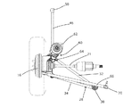
図1は、本発明の一形態を示しており、車輪とそれに接続されたサスペンションの形で、使用時には接続される車両シャーシから分離されて示されている。 FIG. 1 shows an embodiment of the present invention, which is shown in the form of a wheel and a suspension connected thereto, separated from a connected vehicle chassis in use.
そのため、リム14上に装着されたタイヤ12を有する車輪10は、ホイールハブ16にボルト止めされている。これは軸に接続されており、そのアセンブリは、ハブキャリア20上で回転可能に支持されている。ドライブシャフト21は、ディファレンシャルから軸18に通じており、車輪10に駆動トルクを伝達し、車両を推進させる。
Therefore, the
ハブキャリア20は、軸18及びハブ16のためのマウントであって、その上で回転可能とするための適切なベアリング(図示せず)を含むマウントと、内側に伸びる補強フランジであって、ハブキャリア20に剛性を与え、サスペンション要素のための取付ポイントを提供する補強フランジと、を含む。上方フランジ22はハブキャリア20の上方端から延びており、また、前方フランジ24及び後方フランジ26としての2つの側方フランジと、下方フランジ27とが延びている。これらのフランジには、以下の主要なサスペンション要素が接続されている。
The
第一に、反転したウィッシュボーン28は、機構に横方向のコンプライアンスをもたらす。これは、シャーシとの接続ポイント30が単一となるよう反転しており、通常の慣行とは異なっている。単一の接続ポイント30からは、2本のウィッシュボーンアーム32、34が(それぞれ)下方フランジ27上の前方接続ポイント36及び後方接続ポイント38へ向けて延びており、その近傍において、下方フランジ27はハブキャリア20のそれぞれの側方フランジ24、26と接合している。それぞれの接続ポイント30は、接続に適切な調節を提供するボールジョイントを介するものである。
First, the
前方接続ポイント及び後方接続ポイントの別形態は、側方フランジ24、26の開口部を通り、かつ、ウィッシュボーンアーム32、34の端部において対応する円筒形部分を通るロッドである。すなわち、ウィッシュボーンアーム32、34はロッド40に取り付けられており、車輪が上下に移動した場合に必要な相対回転が可能である。このような配置は、発明者らの先願である国際公開第2010/100412号に示されている。
Another form of front connection point and rear connection point is a rod that passes through the openings in the
類似のボールジョイントは、シャーシとの接続ポイント30に含まれており、前後の調整を可能とするために縦方向を向いている。これは、シャーシ上で適切なスタッド42(図1に図示せず)等に取り付けられており、すべての方向へのウィッシュボーンアーム28の運動を制限可能とするラバーブッシング44を介して取り付けられている。
A similar ball joint is included at the
前後のコンプライアンスを提供するために、トレーリングリンク46も設けられている。これは、ラバーブッシング52を介して、類似のスタッドに取り付けられた横方向に位置合わせされた円筒リンク48によって、シャーシに接続されている。これにより、車輪10が上下に移動する際に縦方向の面内においてトレーリングリンク46の容易な回転が可能となり、かつ、サスペンション形状を調整するために他の方向における運動も可能となる。
A trailing
その他方の端部において、トレーリングリンク46は、別のボールジョイントを介して下方フランジ27の前方端に接続されている。または、トレーリングアームは、発明者らの先願である国際公開第2010/100412号に示されているように接続されていてもよい。
At the other end, the trailing
第3の主要なサスペンション要素は、ストラット60である。これは、従来のスプリング及びダンパーのユニットであり、トップマウント62を介してシャーシに接続されており、かつ、ストラット60の下端で固定されると共に、前方フランジ24に2か所でボルト留めされたブラケット64を介して、ハブキャリア20に接続されている。これにより、ストラットは、概ね縦方向におけるハブキャリアの配置を維持すると共に、車輪10の地面との接触を維持するための下方向の力と、車輪10の上方向及び下方向への運動の減衰と、を提供する。
The third major suspension element is a
最後に、トーコントロールリンク66も設けられている。これは、ハブキャリア20からシャーシのハードポイント(図示せず)に向けて延びる固いロッドであり、後部のウィッシュボーンアーム34と概ね平行であるが、そこから上方に間隔を空けて配置されている。両端部のそれぞれにおいて、接続に調節を可能とするボールジョイント又は従来のブッシュ70を介して接続が形成されている。このリンク66は、ウィッシュボーン28及びストラット60によって規制された状態で、高負荷条件下での動的形状の制御を向上させる。これは、低負荷条件下では形状に影響を与えないものの、高負荷の下で追加の支持及び剛性を提供することにより一時的なゆがみを抑制し、それにより形状が性状に維持されることを保証する。
Finally, a
図3は、機構を一方から示している。車輪10がハブ16に取り付けられた状態が、模式的に示されている。反転したウィッシュボーン28は、車両の前方へ向けて上方に角度が付けられているように図示されているロッド40に接続された状態で示されている。同様に、トレーリングアーム46は、そのシャーシマウント50からロッド40のU断面ブラケット54へ向けて下方に角度が付けられている。ストラットは、僅かに前方に角度が付けられており、トップマウント62はブラケット64よりも僅かに前方に位置している。これらの角度や配向は、所望のハンドリング性能を提供するために、サスペンション機構の設計上で調整することができる。
FIG. 3 shows the mechanism from one side. A state in which the
図2は、機構を上方から示しており、トップマウント62がブラケット64の僅かに前方に位置しており、僅かに前方に角度が付けられたストラット60の角度が図示されている。後方ウィッシュボーンアーム34は前方ウィッシュボーンアーム32よりも短く、シャーシへの接続ポイント30が車輪の中央線よりも後方にあることを意味する。これにより、ドライブシャフト21が、接続ポイント30の前方かつウィッシュボーンアーム32の上方を通って、ホイールハブ16に到達するための空間を確保することができる。
FIG. 2 shows the mechanism from above, with the
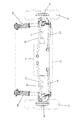
図3は、機構を後方から示しており、ドライブシャフト21が反転したウィッシュボーン28の上方を通っている。後方ウィッシュボーンアーム34の接続ポイント38が、前方ウィッシュボーンアーム32の接続ポイント36よりも僅かに低くなっているように図示されている。これら及び他の角度、並びに配向は、当然ながら、所望のハンドリング性能を提供するためにサスペンション機構の設計上で調整することができる。
FIG. 3 shows the mechanism from the rear, with the
図2及び図3に図示されているように、トーコントロールリンク66は、前方ウィッシュボーンアーム32及び後方ウィッシュボーンアーム34のそれぞれよりも長くなっている。ブッシュ70を介して接続されているシャーシのハードポイントは、ウィッシュボーン28のシャーシへの接続ポイントよりも内側に位置している。同様に、ハブ16への接続ポイントは、前方ウィッシュボーンアーム32及び後方ウィッシュボーンアーム34のそれぞれの接続ポイントよりも外側に位置している。これらの長さ及び取付ポイントは、負荷がかかった際のサスペンションの運動に影響し、上述の有利な効果の提供を助けるものである。
As shown in FIGS. 2 and 3, the
図4は、上述のサスペンション機構が搭載されたコンパクトタウンカーの後方からの模式図を示している。シャーシ72は、必要な取付ポイントを提供し、エンジン及びギアボックス74を収容する。一対のドライブシャフト21が、車両の両側のホイールハブ16へ向けて、ギアボックス72から外側に両方向に突出している。1つの車輪10がそれぞれのホイールハブ16に取り付けられており、反転したウィッシュボーン28、ストラット60、及びトレーリングアーム(図4に図示せず)を含む上述のサスペンション機構によって、各車輪が支持されている。
FIG. 4 shows a schematic view from the rear of a compact town car on which the above suspension mechanism is mounted. The
図4から明らかなように、図示されている機構は、リアエンジン・リア駆動構成の後輪における要請を満足するよう設計されたものである。しかしながら、これは、例えば、駆動輪若しくは非駆動輪である前輪駆動(又は他の)配置等の他の構成に適用可能である。 As is apparent from FIG. 4, the illustrated mechanism is designed to meet the requirements of the rear wheels of the rear engine / rear drive configuration. However, this is applicable to other configurations such as, for example, front wheel drive (or other) arrangements that are drive wheels or non-drive wheels.
この『反転したウィッシュボーン』機構は、独立型サスペンション機構の乗車及びハンドリングに有利な効果をもたらすだけでなく、乗車及び快適性のための前後方向のコンプライアンスと、車両のハンドリング制御(キャンバー制御及びトー制御)のための縦方向のコンプライアンスと、の分離を可能とするために2つの部分でのリンク(反転したウィッシュボーン28に加えてトレーリングリンク46)を有するよう設計されている。ストラット60及びトーコントロールアーム66を有することで、機構全体が極めて軽量であり、かつ、車両の側面あたり3つのリンクと、車両の側面あたり4つの対応した要素とを備えるだけであるため製造コストが低い。
This “inverted wishbone” mechanism not only has an advantageous effect on the riding and handling of the stand-alone suspension mechanism, but also the front-rear compliance for riding and comfort and the vehicle handling control (camber control and toe). It is designed to have a two-part link (trailing
説明された機構は、シャーシへの少数の接続ポイントしか必要とせず、それら接続ポイントをドライブシャフトから十分な空間を取って配置することができる。これは、構成要素のための空間が制限され、車輪がエンジン、ギアボックス等の近傍に搭載され得る、小型の高効率のタウンカーに特に適した機構である。 The described mechanism requires only a few connection points to the chassis, and these connection points can be placed with sufficient space from the drive shaft. This is a mechanism that is particularly suitable for small, high-efficiency town cars where space for components is limited and wheels can be mounted in the vicinity of engines, gearboxes, and the like.
上述の実施形態には、本発明の範囲から逸脱しない限りにおいて様々な変更がなされ得ることは、当然ながら理解されるであろう。 It will be understood that various modifications can be made to the above-described embodiments without departing from the scope of the present invention.
Claims (19)
前記シャーシへの取付けのためのトレーリングリンク接続ポイントへ向けて前記アセンブリから前記支持アームを横断する方向に延びるトレーリングリンクと、
前記2つのポイントから縦方向に間隔が置かれた単一の位置で前記ハブキャリアに接続されると共に、前記シャーシへの取付けのための単一接続ポイントへ向けて前記単一の位置から内側へ向けて延びるトーコントロールリンクと、
を有する、車両サスペンション。 A hub carrier and support arm assembly, the support arm being an arm connected to the hub carrier at two points spaced from each other in the direction of travel, and a support arm connection for attachment to the chassis An assembly that is an arm extending inwardly from the two points toward the point;
A trailing link extending in a direction transverse to the support arm from the assembly toward a trailing link connection point for attachment to the chassis;
Connected to the hub carrier at a single position longitudinally spaced from the two points and inward from the single position toward a single connection point for attachment to the chassis A toe control link extending toward the
Having a vehicle suspension.
前記2つの車輪を前記車両の片側に1つずつ有し、
前記車輪のそれぞれが前記シャーシに、請求項10又は請求項11に記載の車両サスペンションを介して取り付けられている、車両。 A vehicle having a chassis and at least two wheels,
Having the two wheels, one on each side of the vehicle,
A vehicle, wherein each of the wheels is attached to the chassis via a vehicle suspension according to claim 10 or claim 11.
Priority Applications (2)
| Application Number | Priority Date | Filing Date | Title |
|---|---|---|---|
| JP2020165543A JP6979501B2 (en) | 2014-05-08 | 2020-09-30 | Vehicle suspension |
| JP2020165542A JP6979500B2 (en) | 2014-05-08 | 2020-09-30 | Vehicle suspension |
Applications Claiming Priority (3)
| Application Number | Priority Date | Filing Date | Title |
|---|---|---|---|
| GB1408114.5 | 2014-05-08 | ||
| GB1408114.5A GB2525901A (en) | 2014-05-08 | 2014-05-08 | Vehicle suspension |
| PCT/EP2015/060189 WO2015169948A1 (en) | 2014-05-08 | 2015-05-08 | Vehicle suspension |
Related Child Applications (2)
| Application Number | Title | Priority Date | Filing Date |
|---|---|---|---|
| JP2020165542A Division JP6979500B2 (en) | 2014-05-08 | 2020-09-30 | Vehicle suspension |
| JP2020165543A Division JP6979501B2 (en) | 2014-05-08 | 2020-09-30 | Vehicle suspension |
Publications (3)
| Publication Number | Publication Date |
|---|---|
| JP2017514752A true JP2017514752A (en) | 2017-06-08 |
| JP2017514752A5 JP2017514752A5 (en) | 2018-06-14 |
| JP6803234B2 JP6803234B2 (en) | 2020-12-23 |
Family
ID=51032403
Family Applications (3)
| Application Number | Title | Priority Date | Filing Date |
|---|---|---|---|
| JP2016566974A Active JP6803234B2 (en) | 2014-05-08 | 2015-05-08 | Vehicle suspension |
| JP2020165542A Active JP6979500B2 (en) | 2014-05-08 | 2020-09-30 | Vehicle suspension |
| JP2020165543A Active JP6979501B2 (en) | 2014-05-08 | 2020-09-30 | Vehicle suspension |
Family Applications After (2)
| Application Number | Title | Priority Date | Filing Date |
|---|---|---|---|
| JP2020165542A Active JP6979500B2 (en) | 2014-05-08 | 2020-09-30 | Vehicle suspension |
| JP2020165543A Active JP6979501B2 (en) | 2014-05-08 | 2020-09-30 | Vehicle suspension |
Country Status (13)
| Country | Link |
|---|---|
| US (1) | US10226977B2 (en) |
| EP (1) | EP3140135B1 (en) |
| JP (3) | JP6803234B2 (en) |
| KR (1) | KR102387695B1 (en) |
| CN (1) | CN106457939B (en) |
| BR (1) | BR112016024726B1 (en) |
| CA (1) | CA2947797C (en) |
| ES (1) | ES2924405T3 (en) |
| GB (1) | GB2525901A (en) |
| HU (1) | HUE059265T2 (en) |
| MX (1) | MX2016014602A (en) |
| PL (1) | PL3140135T3 (en) |
| WO (1) | WO2015169948A1 (en) |
Families Citing this family (14)
| Publication number | Priority date | Publication date | Assignee | Title |
|---|---|---|---|---|
| US9981519B2 (en) * | 2015-01-29 | 2018-05-29 | Bombardier Recreational Products Inc. | Rear suspension assembly for an off-road vehicle |
| CN105799442B (en) * | 2016-04-19 | 2017-11-17 | 李志联 | Electric automobile chassis suspension assembly |
| DE102016210073A1 (en) | 2016-06-08 | 2017-12-14 | Ford Global Technologies, Llc | Wheel suspension unit for a motor vehicle |
| DE202016103190U1 (en) | 2016-06-08 | 2016-07-08 | Ford Global Technologies, Llc | Wheel suspension unit for a motor vehicle |
| DE102016210072B4 (en) | 2016-06-08 | 2023-12-07 | Ford Global Technologies, Llc | Wheel suspension unit for a motor vehicle |
| CN107839424A (en) * | 2016-09-20 | 2018-03-27 | 同济大学 | Wire controlled four wheel steering and the integrated suspension system of driving |
| DE102016223631B4 (en) * | 2016-11-29 | 2021-06-02 | Audi Ag | Wheel suspension for a wheel of an axle of a motor vehicle |
| CN108162707B (en) * | 2018-01-14 | 2021-01-26 | 郑庆华 | Independent suspension mechanism with front wheel capable of vertically jumping and steering mechanism |
| JP2019166862A (en) * | 2018-03-22 | 2019-10-03 | ヤマハ発動機株式会社 | vehicle |
| KR102563433B1 (en) * | 2018-12-13 | 2023-08-03 | 현대자동차 주식회사 | Suspension system for vehicle |
| LU101143B1 (en) * | 2019-03-04 | 2020-09-04 | Alpha Ec Ind 2018 S A R L | Suspension assembly with a damper for an electric bus |
| DE102021100178A1 (en) * | 2021-01-08 | 2022-07-14 | Dr. Ing. H.C. F. Porsche Aktiengesellschaft | Multi-link motor vehicle axle |
| US11912097B2 (en) * | 2021-01-15 | 2024-02-27 | Segway Technology Co., Ltd. | All-terrain vehicle |
| CN113002654A (en) * | 2021-02-07 | 2021-06-22 | 北京理工大学 | Four-leg wheel-leg type bionic large-stroke adjustable cross-country suspension mechanism and control method |
Citations (5)
| Publication number | Priority date | Publication date | Assignee | Title |
|---|---|---|---|---|
| JPH0274408A (en) * | 1988-09-09 | 1990-03-14 | Mazda Motor Corp | Suspension device for vehicle |
| US5845926A (en) * | 1997-01-21 | 1998-12-08 | Ford Global Technologies, Inc. | Independent suspension apparatus for a wheeled vehicle |
| JP2003146038A (en) * | 2001-11-12 | 2003-05-21 | Nissan Motor Co Ltd | Suspension device |
| JP2006130999A (en) * | 2004-11-04 | 2006-05-25 | Toyota Motor Corp | Suspension device for rear wheel |
| JP2012519621A (en) * | 2009-03-03 | 2012-08-30 | ゴードン・マレー・デザイン・リミテッド | Automotive suspension |
Family Cites Families (19)
| Publication number | Priority date | Publication date | Assignee | Title |
|---|---|---|---|---|
| DE2249971A1 (en) | 1972-10-12 | 1974-04-18 | Daimler Benz Ag | SUSPENSION OF STEERABLE VEHICLE WHEELS, IN PARTICULAR FRONT WHEELS OF MOTOR VEHICLES |
| JPS58182810U (en) * | 1982-05-31 | 1983-12-06 | 日産自動車株式会社 | Rear suspension device |
| DE3306432C2 (en) | 1983-02-24 | 1986-12-11 | Ford-Werke AG, 5000 Köln | Independent wheel suspension for non-steered wheels of motor vehicles |
| DE3331247C2 (en) * | 1983-08-30 | 1986-07-24 | Bayerische Motoren Werke AG, 8000 München | Independent wheel suspension for motor vehicles |
| US4848788A (en) * | 1984-11-15 | 1989-07-18 | Ford Motor Company | Independent rear wheel suspension with offset connection between upper control arm and wheel carrier |
| DE3507141A1 (en) | 1985-02-28 | 1986-09-04 | Bayerische Motoren Werke AG, 8000 München | WHEEL SUSPENSION FOR STEERING WHEELS, IN PARTICULAR FRONT WHEELS, OF MOTOR VEHICLES |
| JPH052322Y2 (en) * | 1986-09-26 | 1993-01-21 | ||
| JPS63145112A (en) * | 1986-12-09 | 1988-06-17 | Honda Motor Co Ltd | Rear suspension deice for automobile |
| JPS63115806U (en) * | 1987-01-23 | 1988-07-26 | ||
| DE3826232A1 (en) * | 1987-08-03 | 1989-02-16 | Honda Motor Co Ltd | WHEEL SUSPENSION SYSTEM |
| JP2710129B2 (en) * | 1988-07-29 | 1998-02-10 | マツダ株式会社 | Vehicle suspension device |
| JP2714969B2 (en) * | 1989-01-13 | 1998-02-16 | マツダ株式会社 | Automotive suspension equipment |
| JP2924306B2 (en) * | 1991-06-03 | 1999-07-26 | 日産自動車株式会社 | Wheel independent suspension |
| JPH05104921A (en) * | 1991-10-18 | 1993-04-27 | Nissan Motor Co Ltd | Trailing arm type double wishbone suspension device |
| DE4206896C2 (en) | 1992-03-05 | 1994-09-01 | Bayerische Motoren Werke Ag | Wheel suspension for steerable wheels of motor vehicles |
| JPH1058932A (en) * | 1996-08-09 | 1998-03-03 | Toyota Motor Corp | Independent suspension type suspension for steering wheels |
| US6945547B2 (en) * | 2002-09-09 | 2005-09-20 | Delphi Technologies, Inc. | Multi-link independent rear suspension assembly |
| JP4432691B2 (en) * | 2004-09-13 | 2010-03-17 | トヨタ自動車株式会社 | Torsion beam suspension system |
| US9469173B2 (en) * | 2011-11-14 | 2016-10-18 | Gordon Murray Design Limited | Vehicle suspension |
-
2014
- 2014-05-08 GB GB1408114.5A patent/GB2525901A/en not_active Withdrawn
-
2015
- 2015-05-08 ES ES15731854T patent/ES2924405T3/en active Active
- 2015-05-08 CN CN201580024109.1A patent/CN106457939B/en active Active
- 2015-05-08 MX MX2016014602A patent/MX2016014602A/en unknown
- 2015-05-08 HU HUE15731854A patent/HUE059265T2/en unknown
- 2015-05-08 CA CA2947797A patent/CA2947797C/en active Active
- 2015-05-08 US US15/306,960 patent/US10226977B2/en active Active
- 2015-05-08 JP JP2016566974A patent/JP6803234B2/en active Active
- 2015-05-08 BR BR112016024726-4A patent/BR112016024726B1/en active IP Right Grant
- 2015-05-08 KR KR1020167033973A patent/KR102387695B1/en active IP Right Grant
- 2015-05-08 WO PCT/EP2015/060189 patent/WO2015169948A1/en active Application Filing
- 2015-05-08 EP EP15731854.4A patent/EP3140135B1/en active Active
- 2015-05-08 PL PL15731854.4T patent/PL3140135T3/en unknown
-
2020
- 2020-09-30 JP JP2020165542A patent/JP6979500B2/en active Active
- 2020-09-30 JP JP2020165543A patent/JP6979501B2/en active Active
Patent Citations (5)
| Publication number | Priority date | Publication date | Assignee | Title |
|---|---|---|---|---|
| JPH0274408A (en) * | 1988-09-09 | 1990-03-14 | Mazda Motor Corp | Suspension device for vehicle |
| US5845926A (en) * | 1997-01-21 | 1998-12-08 | Ford Global Technologies, Inc. | Independent suspension apparatus for a wheeled vehicle |
| JP2003146038A (en) * | 2001-11-12 | 2003-05-21 | Nissan Motor Co Ltd | Suspension device |
| JP2006130999A (en) * | 2004-11-04 | 2006-05-25 | Toyota Motor Corp | Suspension device for rear wheel |
| JP2012519621A (en) * | 2009-03-03 | 2012-08-30 | ゴードン・マレー・デザイン・リミテッド | Automotive suspension |
Also Published As
| Publication number | Publication date |
|---|---|
| JP2021006452A (en) | 2021-01-21 |
| JP6979501B2 (en) | 2021-12-15 |
| BR112016024726B1 (en) | 2022-12-06 |
| EP3140135B1 (en) | 2022-05-04 |
| US20170050484A1 (en) | 2017-02-23 |
| HUE059265T2 (en) | 2022-11-28 |
| MX2016014602A (en) | 2017-05-25 |
| CN106457939B (en) | 2019-12-03 |
| CA2947797C (en) | 2022-07-12 |
| GB2525901A (en) | 2015-11-11 |
| EP3140135A1 (en) | 2017-03-15 |
| KR102387695B1 (en) | 2022-04-18 |
| JP6803234B2 (en) | 2020-12-23 |
| US10226977B2 (en) | 2019-03-12 |
| GB201408114D0 (en) | 2014-06-25 |
| BR112016024726A2 (en) | 2017-08-15 |
| WO2015169948A1 (en) | 2015-11-12 |
| JP6979500B2 (en) | 2021-12-15 |
| PL3140135T3 (en) | 2022-09-12 |
| KR20170005050A (en) | 2017-01-11 |
| BR112016024726A8 (en) | 2021-06-22 |
| ES2924405T3 (en) | 2022-10-06 |
| CN106457939A (en) | 2017-02-22 |
| JP2021004034A (en) | 2021-01-14 |
| CA2947797A1 (en) | 2015-11-12 |
Similar Documents
| Publication | Publication Date | Title |
|---|---|---|
| JP6979500B2 (en) | Vehicle suspension | |
| JP5784509B2 (en) | Automotive suspension | |
| US10266025B2 (en) | Suspension module having an air spring pedestal | |
| CN102317091B (en) | Suspension device | |
| US8517140B2 (en) | Independent rear suspension kit | |
| US9469173B2 (en) | Vehicle suspension | |
| CN103121387B (en) | MacPherson air suspension and assembly method thereof | |
| CN203198673U (en) | Macphersan air suspension | |
| WO2010055469A1 (en) | Vehicle independent suspension | |
| GB2582330A (en) | Steering axle assembly | |
| GB2529175A (en) | Vehicle suspension | |
| KR20120008877A (en) | Strut type suspension system for vehicle | |
| GB2607076A (en) | Vehicle wheel suspension | |
| KR20030024378A (en) | Rear multi-link suspension having a dual upper arm | |
| KR20050060702A (en) | Suspension of mcpherson strut type |
Legal Events
| Date | Code | Title | Description |
|---|---|---|---|
| A521 | Request for written amendment filed |
Free format text: JAPANESE INTERMEDIATE CODE: A523 Effective date: 20170120 |
|
| A521 | Request for written amendment filed |
Free format text: JAPANESE INTERMEDIATE CODE: A523 Effective date: 20180424 |
|
| A621 | Written request for application examination |
Free format text: JAPANESE INTERMEDIATE CODE: A621 Effective date: 20180424 |
|
| A977 | Report on retrieval |
Free format text: JAPANESE INTERMEDIATE CODE: A971007 Effective date: 20190207 |
|
| A131 | Notification of reasons for refusal |
Free format text: JAPANESE INTERMEDIATE CODE: A131 Effective date: 20190226 |
|
| A521 | Request for written amendment filed |
Free format text: JAPANESE INTERMEDIATE CODE: A523 Effective date: 20190523 |
|
| A02 | Decision of refusal |
Free format text: JAPANESE INTERMEDIATE CODE: A02 Effective date: 20190702 |
|
| C60 | Trial request (containing other claim documents, opposition documents) |
Free format text: JAPANESE INTERMEDIATE CODE: C60 Effective date: 20191101 |
|
| C116 | Written invitation by the chief administrative judge to file amendments |
Free format text: JAPANESE INTERMEDIATE CODE: C116 Effective date: 20191119 |
|
| C22 | Notice of designation (change) of administrative judge |
Free format text: JAPANESE INTERMEDIATE CODE: C22 Effective date: 20191119 |
|
| C22 | Notice of designation (change) of administrative judge |
Free format text: JAPANESE INTERMEDIATE CODE: C22 Effective date: 20200512 |
|
| C13 | Notice of reasons for refusal |
Free format text: JAPANESE INTERMEDIATE CODE: C13 Effective date: 20200630 |
|
| A521 | Request for written amendment filed |
Free format text: JAPANESE INTERMEDIATE CODE: A523 Effective date: 20200930 |
|
| C23 | Notice of termination of proceedings |
Free format text: JAPANESE INTERMEDIATE CODE: C23 Effective date: 20201020 |
|
| C03 | Trial/appeal decision taken |
Free format text: JAPANESE INTERMEDIATE CODE: C03 Effective date: 20201124 |
|
| C30A | Notification sent |
Free format text: JAPANESE INTERMEDIATE CODE: C3012 Effective date: 20201124 |
|
| A61 | First payment of annual fees (during grant procedure) |
Free format text: JAPANESE INTERMEDIATE CODE: A61 Effective date: 20201130 |
|
| R150 | Certificate of patent or registration of utility model |
Ref document number: 6803234 Country of ref document: JP Free format text: JAPANESE INTERMEDIATE CODE: R150 |
|
| S533 | Written request for registration of change of name |
Free format text: JAPANESE INTERMEDIATE CODE: R313533 |
|
| R350 | Written notification of registration of transfer |
Free format text: JAPANESE INTERMEDIATE CODE: R350 |
|
| R250 | Receipt of annual fees |
Free format text: JAPANESE INTERMEDIATE CODE: R250 |