JP2017513604A - Intravascular device, system and method having separate sections with core elements engaged - Google Patents
Intravascular device, system and method having separate sections with core elements engaged Download PDFInfo
- Publication number
- JP2017513604A JP2017513604A JP2016563781A JP2016563781A JP2017513604A JP 2017513604 A JP2017513604 A JP 2017513604A JP 2016563781 A JP2016563781 A JP 2016563781A JP 2016563781 A JP2016563781 A JP 2016563781A JP 2017513604 A JP2017513604 A JP 2017513604A
- Authority
- JP
- Japan
- Prior art keywords
- distal
- proximal
- core member
- sensing
- engagement structure
- Prior art date
- Legal status (The legal status is an assumption and is not a legal conclusion. Google has not performed a legal analysis and makes no representation as to the accuracy of the status listed.)
- Granted
Links
Images


Classifications
-
- A—HUMAN NECESSITIES
- A61—MEDICAL OR VETERINARY SCIENCE; HYGIENE
- A61B—DIAGNOSIS; SURGERY; IDENTIFICATION
- A61B5/00—Measuring for diagnostic purposes; Identification of persons
- A61B5/68—Arrangements of detecting, measuring or recording means, e.g. sensors, in relation to patient
- A61B5/6846—Arrangements of detecting, measuring or recording means, e.g. sensors, in relation to patient specially adapted to be brought in contact with an internal body part, i.e. invasive
- A61B5/6847—Arrangements of detecting, measuring or recording means, e.g. sensors, in relation to patient specially adapted to be brought in contact with an internal body part, i.e. invasive mounted on an invasive device
- A61B5/6851—Guide wires
-
- A—HUMAN NECESSITIES
- A61—MEDICAL OR VETERINARY SCIENCE; HYGIENE
- A61B—DIAGNOSIS; SURGERY; IDENTIFICATION
- A61B5/00—Measuring for diagnostic purposes; Identification of persons
- A61B5/02—Detecting, measuring or recording pulse, heart rate, blood pressure or blood flow; Combined pulse/heart-rate/blood pressure determination; Evaluating a cardiovascular condition not otherwise provided for, e.g. using combinations of techniques provided for in this group with electrocardiography or electroauscultation; Heart catheters for measuring blood pressure
- A61B5/021—Measuring pressure in heart or blood vessels
- A61B5/0215—Measuring pressure in heart or blood vessels by means inserted into the body
-
- A—HUMAN NECESSITIES
- A61—MEDICAL OR VETERINARY SCIENCE; HYGIENE
- A61B—DIAGNOSIS; SURGERY; IDENTIFICATION
- A61B5/00—Measuring for diagnostic purposes; Identification of persons
- A61B5/02—Detecting, measuring or recording pulse, heart rate, blood pressure or blood flow; Combined pulse/heart-rate/blood pressure determination; Evaluating a cardiovascular condition not otherwise provided for, e.g. using combinations of techniques provided for in this group with electrocardiography or electroauscultation; Heart catheters for measuring blood pressure
- A61B5/026—Measuring blood flow
- A61B5/0265—Measuring blood flow using electromagnetic means, e.g. electromagnetic flowmeter
- A61B5/027—Measuring blood flow using electromagnetic means, e.g. electromagnetic flowmeter using catheters
-
- A—HUMAN NECESSITIES
- A61—MEDICAL OR VETERINARY SCIENCE; HYGIENE
- A61B—DIAGNOSIS; SURGERY; IDENTIFICATION
- A61B2562/00—Details of sensors; Constructional details of sensor housings or probes; Accessories for sensors
- A61B2562/12—Manufacturing methods specially adapted for producing sensors for in-vivo measurements
-
- A—HUMAN NECESSITIES
- A61—MEDICAL OR VETERINARY SCIENCE; HYGIENE
- A61B—DIAGNOSIS; SURGERY; IDENTIFICATION
- A61B2562/00—Details of sensors; Constructional details of sensor housings or probes; Accessories for sensors
- A61B2562/22—Arrangements of medical sensors with cables or leads; Connectors or couplings specifically adapted for medical sensors
- A61B2562/225—Connectors or couplings
- A61B2562/227—Sensors with electrical connectors
Abstract
血管内デバイス、システム及び方法が開示される。幾つかの例において、血管内デバイスは、係合されたコア要素を有する分離セクションを含むガイドワイヤである。例えば、センシングガイドワイヤは、近位芯部材及び少なくとも1つの近位電気導体を有する近位部分と、近位部分に結合される遠位部分であって、遠位部分は、遠位芯部材、センシング要素、及び、センシング要素に結合される少なくとも1つの遠位電気導体を有する、遠位部分とを有し、近位及び遠位芯部材の係合構造は係合され、少なくとも1つの遠位電気導体は、少なくとも1つの近位電気導体がセンシング要素と電気通信状態にあるように少なくとも1つの近位電気導体に結合される。斯様な血管内デバイス及び関連したシステムを作成、製造及び/又は組み立てを行う方法も提供される。Intravascular devices, systems and methods are disclosed. In some examples, the intravascular device is a guidewire that includes a separation section having an engaged core element. For example, the sensing guidewire is a proximal portion having a proximal core member and at least one proximal electrical conductor, and a distal portion coupled to the proximal portion, the distal portion being a distal core member, A distal portion having a sensing element and at least one distal electrical conductor coupled to the sensing element, wherein the proximal and distal core member engagement structures are engaged and at least one distal The electrical conductor is coupled to the at least one proximal electrical conductor such that the at least one proximal electrical conductor is in electrical communication with the sensing element. A method for creating, manufacturing and / or assembling such an intravascular device and associated system is also provided.
Description
本開示は、血管内デバイス、システム及び方法に関する。幾つかの実施形態において、血管内デバイスは、係合されるコア要素を有する別々のセクションを含むガイドワイヤである。 The present disclosure relates to intravascular devices, systems and methods. In some embodiments, the intravascular device is a guidewire that includes separate sections with engaged core elements.
心臓病は、非常に深刻なものであり、多くの場合、命を救うために緊急手術を要する。心臓病の主な原因は、血管内のプラークの蓄積であり、これは、最終的に血管を塞ぐ。塞がれた血管を広げるために利用可能な共通の処理オプションは、風船血管形成術、回転粥腫切除及び血管内ステントを含む。昔から、外科医は、処理をガイドするために血管の管腔のシルエットの外部形状を示す平らな画像であるX線蛍光透視画像に頼っていた。不都合にも、X線蛍光透視画像によれば、閉塞の原因となる狭窄の正確な範囲及び配向についての多くの不確実性が存在し、狭窄の正確な位置を見つけるのを困難にする。加えて、再狭窄が同じ場所で発生し得ることが知られているにもかかわらず、X線によって手術後に血管内の状態をチェックすることは困難である。 Heart disease is very serious and often requires emergency surgery to save lives. The main cause of heart disease is the buildup of plaque in the blood vessels, which eventually plugs the blood vessels. Common processing options available to widen the blocked vessel include balloon angioplasty, rotational atherectomy and endovascular stents. Traditionally, surgeons have relied on X-ray fluoroscopic images, which are flat images showing the external shape of the vessel lumen silhouette to guide the process. Unfortunately, with X-ray fluoroscopic images, there is a lot of uncertainty about the exact extent and orientation of the stenosis that causes occlusion, making it difficult to find the exact location of the stenosis. In addition, although it is known that restenosis can occur at the same location, it is difficult to check the intravascular condition after surgery with x-rays.
血管における狭窄の重症度を評価するための現在認められた技術は、虚血をもたらす損傷を含む、血流予備量比(FFR;fractional flow reserve)である。FFRは、(狭窄の近位側で行われる)近位圧力測定に対する(狭窄の遠位側で行われる)遠位圧力測定の比の計算である。FFRは、処理が必要とされる範囲において妨害物が血管の範囲内の血流を制限するかどうかに関して決定を可能にする狭窄重症度のインデックスを与える。健康的な血管におけるFFRの通常の値は1.00である一方で、約0.80より低い値は概して重大であり、処理を必要とすると考えられる。 A currently accepted technique for assessing the severity of stenosis in blood vessels is the fractional flow reserve (FFR), including ischemic damage. FFR is the calculation of the ratio of the distal pressure measurement (performed on the distal side of the stenosis) to the proximal pressure measurement (performed on the proximal side of the stenosis). FFR provides an index of stenosis severity that allows a determination as to whether an obstruction restricts blood flow within a vessel in the area where treatment is needed. While normal values for FFR in healthy blood vessels are 1.00, values below about 0.80 are generally significant and are considered to require treatment.
多くの場合、血管内カテーテル及びガイドワイヤは、血管内の圧力を測定するため、血管の内側管腔を視覚化するため、及び/又は、そうでなければ、血管に関連したデータを取得するために利用される。現在まで、圧力センサ、イメージング要素及び/又は他の電子、光又は電気光学部品を含むガイドワイヤは、斯様な部品を含まない標準のガイドワイヤと比較して低減されたパフォーマンス特性に苦しんでいた。例えば、電子部品を含む前のガイドワイヤの処理パフォーマンスは、幾つかの例において、電子部品の導体又は通信ラインのために必要とされる空間を構成した後に芯線のために利用可能な制限された空間により、電子部品を含む堅いハウジングの安定性により、及び/又は、ガイドワイヤ内で利用可能な制限された空間において電子部品の機能を与えることに関連付けられた他の制約により、妨げられる。更に、その小さな直径のため、多くの例において、ガイドワイヤの近位のコネクタ部分(即ち、ガイドワイヤの電子部品と関連したコントローラ又はプロセッサとの間の通信を促進するコネクタ)は、壊れやすく、ねじれる傾向があり、これは、ガイドワイヤの機能を無効にし得る。このために、外科医は、近位コネクタを再び取り付けるときに、ガイドワイヤを破壊することを恐れて手順の間に近位コネクタをガイドワイヤから除去するのは気が進まない。更に、近位コネクタに結合されるガイドワイヤを有することは、ガイドワイヤの操作性及び処理を制限する。 In many cases, intravascular catheters and guidewires measure pressure within the blood vessel, visualize the inner lumen of the blood vessel, and / or otherwise obtain blood vessel related data. Used for To date, guidewires containing pressure sensors, imaging elements and / or other electronic, optical or electro-optic components have suffered from reduced performance characteristics compared to standard guidewires that do not contain such components. . For example, the processing performance of a guidewire prior to containing an electronic component is limited in some examples available for the core wire after constructing the space required for the conductor or communication line of the electronic component. Space is hindered by the stability of the rigid housing containing the electronic components and / or other constraints associated with providing the functionality of the electronic components in the limited space available within the guidewire. Furthermore, because of its small diameter, in many instances, the proximal connector portion of the guidewire (i.e., the connector that facilitates communication between the guidewire electronics and the associated controller or processor) is fragile, There is a tendency to twist, which can negate the function of the guidewire. Because of this, surgeons are reluctant to remove the proximal connector from the guide wire during the procedure for fear of breaking the guide wire when reattaching the proximal connector. Further, having a guide wire coupled to the proximal connector limits the operability and processing of the guide wire.
更に、既存の圧力及びフローガイドワイヤに関する問題は、多くの別個の部品の複雑なアセンブリを必要とすることにある。その複雑な組立プロセスは、ガイドワイヤの設計パフォーマンス上の制約を有する。ワイヤの長さを短くする別個の伝導性ワイヤの使用は、より多くの支持的コアのために利用可能な空間を低減し、伝導性バンドを有する乏しいハンダ接合部に起因して、使用の間に多数の問題、絶縁の問題に起因して電気的短絡、及び、精巧な伝導性ワイヤの破損をもたらし得る。 Furthermore, a problem with existing pressure and flow guidewires is that they require a complex assembly of many separate parts. The complex assembly process has constraints on guidewire design performance. The use of a separate conductive wire that shortens the length of the wire reduces the space available for more supportive cores, and due to the poor solder joints with conductive bands during use Many problems, electrical shorts due to insulation problems, and fine conductive wire breakage can result.
従って、1又はそれ以上の電子、光又は電気光学部品を含む改良された血管内デバイス、システム及び方法の必要性が残る。 Accordingly, there remains a need for improved intravascular devices, systems and methods that include one or more electronic, optical or electro-optic components.
本開示は、係合するコア要素により一緒に結合される別々のセクションを有するガイドワイヤを含む血管内デバイス、システム及び方法に指向される。 The present disclosure is directed to intravascular devices, systems and methods that include guidewires having separate sections joined together by engaging core elements.
本開示は、従来のセンシングガイドワイヤのアセンブリ及びパフォーマンスの問題を回避するより強力なセンシングガイドワイヤを提供する。本開示のガイドワイヤは、ガイドワイヤの異なる部分の結合を促進する1又はそれ以上の遷移セクションを有する。センサの任意のタイプは、本開示のガイドワイヤに接続され得る。特定の実施形態において、単一のセンサのみがガイドワイヤに接続される。他の実施形態において、複数のセンサは、ガイドワイヤに接続される。センサの全てが同じであってもよい。代わりに、センサは、互いに異なっていてもよく、血管内の異なる特性を測定してもよい。例示的なセンサは、圧力、フロー及び温度センサである。概して、圧力センサの任意のタイプは、圧抵抗もの、光及び/又はその組み合わせを含む本開示のガイドワイヤとともに用いられてもよい。特定の実施形態において、圧力センサは、結晶質の半導体材料を含む。同様に、フローセンサの任意のタイプは、本開示のガイドワイヤとともに用いられてもよい。特定の実施形態において、フローセンサは、超音波振動子(例えばドップラー超音波振動子)を含む。ガイドワイヤは、圧力センサ及びフローセンサの双方を含み得る。 The present disclosure provides a more powerful sensing guidewire that avoids conventional sensing guidewire assembly and performance problems. The guidewire of the present disclosure has one or more transition sections that facilitate bonding of different portions of the guidewire. Any type of sensor can be connected to the guidewire of the present disclosure. In certain embodiments, only a single sensor is connected to the guidewire. In other embodiments, the plurality of sensors are connected to a guide wire. All of the sensors may be the same. Alternatively, the sensors may be different from each other and may measure different characteristics within the blood vessel. Exemplary sensors are pressure, flow and temperature sensors. In general, any type of pressure sensor may be used with the guidewire of the present disclosure, including piezoresistive, light and / or combinations thereof. In certain embodiments, the pressure sensor includes a crystalline semiconductor material. Similarly, any type of flow sensor may be used with the guidewire of the present disclosure. In certain embodiments, the flow sensor includes an ultrasonic transducer (eg, a Doppler ultrasonic transducer). The guide wire can include both a pressure sensor and a flow sensor.
本開示の他の態様は、血管内デバイスを製造及び/又は組み立てを行うための方法を提供する。本方法は、近位芯部材及び少なくとも1つの近位の電気導体を有する近位部分を設けるステップであって、前記近位芯部材の遠位セクションは、第1の結合構造を含む、ステップと、遠位芯部材、センシング要素、及び、前記センシング要素に結合される少なくとも1つの遠位電気導体を有する遠位部分を設けるステップであって、前記遠位芯部材の近位セクションは、第2の結合構造を含む、ステップと、前記近位部分を前記遠位部分に結合するステップとを有し、前記結合するステップは、前記近位芯部材を前記遠位芯部材に固定するステップであって、前記近位芯部材を前記遠位芯部材に固定することは、前記第1の結合構造を前記第2の結合構造と係合させることを含む、ステップと、前記少なくとも1つの近位電気導体が前記センシング要素と電気通信状態になるように前記少なくとも1つの近位電気導体を前記少なくとも1つの遠位電気導体に電気的に結合するステップとを含む。 Another aspect of the present disclosure provides a method for manufacturing and / or assembling an intravascular device. The method includes providing a proximal portion having a proximal core member and at least one proximal electrical conductor, wherein the distal section of the proximal core member includes a first coupling structure; Providing a distal portion having a distal core member, a sensing element, and at least one distal electrical conductor coupled to the sensing element, wherein the proximal section of the distal core member is a second And coupling the proximal portion to the distal portion, the coupling step being a step of securing the proximal core member to the distal core member. Affixing the proximal core member to the distal core member includes engaging the first coupling structure with the second coupling structure; and the at least one proximal electrical The conductor is And a step of electrically coupling the at least one proximal electrical conductors so that the ring element and the electrical communication to the at least one distal electrical conductors.
別の態様において、センシングガイドワイヤが提供される。ガイドワイヤは、近位芯部材及び少なくとも1つの近位電気導体を有する近位部分と、前記近位部分に結合される遠位部分とを含み得る。遠位部分は、遠位芯部材、センシング要素、及び、前記センシング要素に結合される少なくとも1つの遠位電気導体を有する。前記近位芯部材及び前記遠位芯部材の係合構造は、係合され、前記少なくとも1つの遠位電気導体は、前記少なくとも1つの近位の電気導体が前記センシング要素と電気通信状態になるように前記少なくとも1つの近位電気導体に結合される。 In another aspect, a sensing guidewire is provided. The guidewire may include a proximal portion having a proximal core member and at least one proximal electrical conductor, and a distal portion coupled to the proximal portion. The distal portion has a distal core member, a sensing element, and at least one distal electrical conductor coupled to the sensing element. The engagement structure of the proximal core member and the distal core member is engaged, and the at least one distal electrical conductor is in electrical communication with the sensing element. Is coupled to the at least one proximal electrical conductor.
本開示の他の態様は、血管内の特性を測定するための方法を提供する。本方法が、本開示によるセンシングガイドワイヤを設けるステップと、前記ガイドワイヤを血管に挿入するステップと、血管内の1又はそれ以上の特性を測定するために前記ガイドワイヤの1又はそれ以上のセンシング要素を利用するステップとを含み得る。 Another aspect of the present disclosure provides a method for measuring intravascular properties. The method includes providing a sensing guidewire according to the present disclosure; inserting the guidewire into a blood vessel; and sensing one or more of the guidewire to measure one or more characteristics in the blood vessel. Utilizing the element.
本開示の追加の態様、特徴及び利点は、以下の詳細な説明から明らかになるだろう。 Additional aspects, features and advantages of the present disclosure will become apparent from the following detailed description.
本開示の例示的な実施形態は、添付図面を参照して述べられるだろう。 Exemplary embodiments of the present disclosure will be described with reference to the accompanying drawings.
本開示の原理の理解を促進するために、図面において示される実施形態が参照され、特定の言語が同じものを述べるために用いられるだろう。それにもかかわらず、開示の範囲への限定が意図されないことが理解される。述べられたデバイス、システム及び方法に対する任意の変更及び更なる変形、並びに、本開示の原理の任意の更なる適用は、当業者に対して通常生じるように、本開示の範囲内において完全に予測され、及び、含まれる。とりわけ、一実施形態に関して述べられた特徴、成分及び/又はステップが本開示の他の実施形態に関して述べられた特徴、成分及び/又はステップと組み合わせられ得ることは完全に予測される。しかしながら、簡潔さのために、これらの組み合わせの多数の繰り返しは別々に述べられないだろう。 In order to facilitate an understanding of the principles of the present disclosure, reference will be made to the embodiments illustrated in the drawings, and specific language will be used to describe the same. Nevertheless, it is understood that no limitation to the scope of the disclosure is intended. Any changes and further modifications to the described devices, systems and methods, as well as any further application of the principles of the present disclosure will be fully anticipated within the scope of the present disclosure, as would normally occur to those skilled in the art. And included. In particular, it is fully anticipated that the features, components and / or steps described with respect to one embodiment may be combined with the features, components and / or steps described with respect to other embodiments of the present disclosure. However, for the sake of brevity, many repetitions of these combinations will not be described separately.
ここで用いられるように、"フレキシブルな長尺部材"又は"長尺のフレキシブルな部材"は、少なくとも、患者の血管系に挿入され得る任意の細い、長い、フレキシブルな構造を含む。本開示の"フレキシブルな長尺部材"の示された実施形態は、フレキシブルな長尺部材の外径を規定する円形断面形状を有する円柱形状を有する一方で、他の例において、フレキシブルな長尺部材の全て又は一部は、他の幾何学的断面形状(例えば、卵形、矩形、楕円形等)又は非幾何学的断面形状を有してもよい。フレキシブルな長尺部材は、例えば、ガイドワイヤ及びカテーテルを含む。その点で、カテーテルは、他の器具を受けるため及び/又はガイドするためにその長さに沿って延在する管腔を含んでもよく、又は、含まなくてもよい。カテーテルが管腔を含む場合、管腔は、デバイスの断面形状に対して中央に置かれてもよく、又は、オフセットされてもよい。 As used herein, a “flexible elongate member” or “elongate flexible member” includes at least any thin, long, flexible structure that can be inserted into a patient's vasculature. While the illustrated embodiment of the “flexible elongate member” of the present disclosure has a cylindrical shape with a circular cross-sectional shape that defines the outer diameter of the flexible elongate member, in other examples, the flexible elongate member All or some of the members may have other geometric cross-sectional shapes (eg, oval, rectangular, elliptical, etc.) or non-geometric cross-sectional shapes. Flexible elongate members include, for example, guide wires and catheters. In that regard, the catheter may or may not include a lumen extending along its length to receive and / or guide other instruments. If the catheter includes a lumen, the lumen may be centered or offset with respect to the cross-sectional shape of the device.
ほとんどの実施形態において、本開示のフレキシブルな長尺部材は、1又はそれ以上の電子、光、又は電気光学部品を含む。例えば、限定されるものではないが、フレキシブルな長尺部材は、部品の以下のタイプの1又はそれ以上を含み得る:圧力センサ、フローセンサ、温度センサ、イメージング要素、光ファイバ、超音波振動子、反射体、ミラー、プリズム、アブレーション要素、RF電極、導体及び/又はその組み合わせ。概して、これらの部品は、フレキシブルな長尺部材が配置される解剖の血管又は他の部分に関連したデータを取得するように構成される。多くの場合、これらの部品は、表示及び/又は処理のために外部デバイスにデータを通信するように構成される。幾つかのアスペクトにおいて、本開示の実施形態は、医療的及び非医療的なアプリケーションを含む、血管の管腔内においてイメージングのためのイメージングデバイスを含む。しかしながら、本開示の幾つかの実施形態は、人間の血管系における使用に特に適している。血管内空間のイメージング、とりわけ人間の血管系の内壁は、超音波(多くの場合血管内超音波("IVUS")及び心臓内心エコー検査法("ICE")と呼ばれる)及び光コヒーレンス断層撮影("OCT")を含む、多数の異なる技術により達成され得る。他の例において、赤外線、熱的又は他の画像診断法が利用される。 In most embodiments, the flexible elongate member of the present disclosure includes one or more electronic, optical, or electro-optic components. For example, without limitation, a flexible elongate member may include one or more of the following types of parts: pressure sensor, flow sensor, temperature sensor, imaging element, optical fiber, ultrasonic transducer , Reflectors, mirrors, prisms, ablation elements, RF electrodes, conductors and / or combinations thereof. In general, these components are configured to acquire data related to the anatomical blood vessel or other portion in which the flexible elongate member is placed. In many cases, these components are configured to communicate data to external devices for display and / or processing. In some aspects, embodiments of the present disclosure include an imaging device for imaging within the lumen of a blood vessel, including medical and non-medical applications. However, some embodiments of the present disclosure are particularly suitable for use in the human vasculature. Imaging of intravascular space, especially the inner wall of the human vasculature, can be performed with ultrasound (often referred to as intravascular ultrasound ("IVUS") and intracardiac echocardiography ("ICE")) and optical coherence tomography ( It can be achieved by a number of different techniques, including "OCT"). In other examples, infrared, thermal or other diagnostic imaging methods are utilized.
本開示の電子、光及び/又は電気光学部品は、多くの場合、フレキシブルな長尺部材の遠位部分内に配置される。ここで用いられるように、フレキシブルな長尺部材の"遠位部分"は、中間ポイントから遠位先端までのフレキシブルな長尺部材の任意の部分を含む。フレキシブルな長尺部材は硬質であり得るので、本開示の幾つかの実施形態は、電子部品を受けるために遠位部分においてハウジング部分を含むだろう。斯様なハウジング部分は、長尺部材の遠位部分に取り付けられるチューブ構造であり得る。幾つかのフレキシブルな長尺部材は、チューブ状であり、電子部品が遠位部分内に配置され得る1又はそれ以上の管腔を有する。 The electronic, optical and / or electro-optic components of the present disclosure are often disposed within the distal portion of the flexible elongate member. As used herein, the “distal portion” of a flexible elongate member includes any portion of the flexible elongate member from an intermediate point to a distal tip. Because the flexible elongate member can be rigid, some embodiments of the present disclosure will include a housing portion at the distal portion for receiving electronic components. Such a housing portion may be a tube structure attached to the distal portion of the elongate member. Some flexible elongate members are tubular and have one or more lumens in which electronic components can be placed within the distal portion.
電子、光及び/又は電気光学部品及び関連した通信ラインは、フレキシブルな長尺部材の直径が非常に小さくなるのを可能にするようにサイズ化及び形成される。例えば、(ここで述べられる1又はそれ以上の電子、光及び/又は電子光学部品を含む)ガイドワイヤ又はカテーテルのような長尺部材の外径は、約0.0007インチ(0.0178mm)〜約0.118インチ(3.0mm)である。幾つかの特定の実施形態によれば、約0.014インチ(0.3556mm)、約0.018インチ(0.4572mm)及び約.035インチ(.889mm)の外径を有する。従って、本願の電子、光及び/又は電子光部品を取り込むフレキシブルな長尺部材は、四肢の静脈及び動脈、腎動脈、脳の内外の血管及び他の管腔を含む、心臓を部分的に又は直ちに囲むものに加えて、人間の患者の範囲内の多種多様な管腔における使用に適している。 Electronic, optical and / or electro-optic components and associated communication lines are sized and formed to allow the diameter of the flexible elongated member to be very small. For example, the outer diameter of an elongate member such as a guidewire or catheter (including one or more of the electronic, optical and / or electro-optic components described herein) can be from about 0.0007 inches (0.0178 mm) About 0.118 inch (3.0 mm). According to some specific embodiments, about 0.014 inch (0.3556 mm), about 0.018 inch (0.4572 mm), and about. It has an outer diameter of 035 inches (0.889 mm). Accordingly, the flexible elongate member that captures the electronic, optical, and / or electro-optic components of the present application may include a portion of the heart, including limb veins and arteries, renal arteries, blood vessels inside and outside the brain, and other lumens In addition to immediate surround, it is suitable for use in a wide variety of lumens within the scope of a human patient.
ここで用いられる"接続される"及びそのバリエーションは、例えば他の要素に、上に、内に接着又はそうでなければ固定されるような直接接続、及び、1又はそれ以上の要素が接続された要素の間に配置される間接的な接続を含む。 As used herein, “connected” and variations thereof include, for example, a direct connection, such as being glued or otherwise secured within, and one or more elements connected to other elements. Including indirect connections placed between other elements.
ここで用いられる「固定される」及びそのバリエーションは、例えば他の要素に、上に、内に接着又はそうでなければ固定されるような、要素が他の要素に直接固定される方法、及び、1又はそれ以上の要素が固定された要素の間に配置される場合に2つの要素を一緒に固定する間接的な技術を含む。 As used herein, “fixed” and variations thereof are, for example, methods in which an element is directly fixed to another element, such as adhered to or otherwise fixed within, and Includes indirect techniques to secure two elements together when one or more elements are placed between the fixed elements.
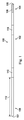
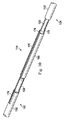
図1を参照すると、本開示の一実施形態による血管内デバイス100の一部が示されている。その点で、血管内デバイス100は、中心部分102、遠位端105に隣り合う遠位部分104、近位端107に隣り合う近位部分106を有するフレキシブルな長尺部材を含む。部品108は、遠位先端105の近くで遠位部分104内に配置される。概して、部品108は、1又はそれ以上の電子、光、又は、電子光部品を表わす。その点で、部品108は、圧力センサ、フローセンサ、温度センサ、イメージング要素、光ファイバ、超音波振動子、反射体、ミラー、プリズム、アブレーション要素、RF電極、導体及び/又はその組み合わせである。部品の特定のタイプ又は部品の組み合わせは、血管内デバイスの使用目的に基づいて選択され得る。幾つかの例において、部品108は、遠位先端105から10cmより短く、5より短く、又は、3cmより短い位置に配置される。幾つかの例において、部品108は、フレキシブルな長尺部材102のハウジング内に配置される。その点で、ハウジングは、幾つかの例における遠位部分104の他の部品に固定される別々の部品である。他の例において、ハウジングは、遠位部分104の部品の一部として一体的に形成される。
Referring to FIG. 1, a portion of an
また、血管内デバイス100は、デバイスの近位部分106と隣り合うコネクタ110を含む。その点で、コネクタ110は、距離112により血管内デバイス100の近位端107から間隔を置かれる。概して、距離112は、血管内デバイス100の全体の長さの0%〜50%である。血管内デバイスの全体長さが任意の長さであり得る一方で、幾つかの実施形態において、全体の長さは、約1300mm〜約4000mmであり、幾つかの特定の実施形態によれば、1400mm、1900mm及び3000mmの長さを有する。従って、幾つかの例において、コネクタ110は、近位端107に配置される。他の例において、コネクタ110は、近位端107から間隔を置かれる。例えば、幾つかの例において、コネクタ110は、約0mm〜約1400mm近位端107から間隔を置かれる。幾つかの特定の実施形態において、コネクタ110は、0mm、300mm及び1400mmの距離により近位端から間隔を置かれる。
The
コネクタ110は、血管内デバイス100と他のデバイスとの間の通信を促進するように構成される。より詳しくは、幾つかの実施形態において、コネクタ110は、計算デバイス又はプロセッサのような他のデバイスへの、部品108により取得されたデータの通信を促進するように構成される。従って、幾つかの実施形態において、コネクタ110は電気コネクタである。斯様な例において、コネクタ110は、フレキシブルな長尺部材102の長さに沿って延在するとともに部品108に電気的に結合される1又はそれ以上の電気導体への電気接続を提供する。他の実施形態において、コネクタ110は光コネクタである。斯様な例において、コネクタ110は、フレキシブルな長尺部材102の長さに沿って延在するとともに部品108に光学的に結合される1又はそれ以上の光通信経路(例えば、光ファイバケーブル)への光学接続を提供する。更に、幾つかの実施形態において、コネクタ110は、部品108に結合される電気導体及び光通信経路の双方に対する電気及び光接続を提供する。その点で、部品108が幾つかの例において複数の要素を含むことが留意されるべきである。コネクタ110は、他のデバイスへの直接又は間接的物理的接続を提供するように構成される。幾つかの例において、コネクタ110は、血管内デバイス100と他のデバイスとの間のワイヤレス通信を促進するように構成される。概して、任意の現在の又は将来の開発されるワイヤレスプロトコルが利用されてもよい。更に他の例において、コネクタ110は、他のデバイスへの物理的及びワイヤレス接続の双方を促進する。
上記したように、幾つかの例において、コネクタ110は、血管内デバイス100の部品108と外部デバイスとの間の接続を提供する。従って、幾つかの実施形態において、1又はそれ以上の電気導体、1又はそれ以上の光経路及び/又はその組み合わせは、コネクタ110と部品108との間の通信を促進するためにコネクタ110と部品108との間に血管内デバイス100の長さに沿って延在する。概して、任意の数の電気導体、光経路及び/又はその組み合わせは、コネクタ110と部品108との間の血管内デバイス100の長さに沿って延在し得る。幾つかの例において、1〜10の電気導体及び/又は光経路は、コネクタ110と部品108との間の血管内デバイス100の長さに沿って延在する。通信経路の数及び電気導体及び光経路の数は、部品108の所望の機能及び斯様な機能を提供するために部品108を規定する対応する要素により決定される。
As described above, in some examples, the
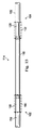
図1及び図2に示されるように、血管内デバイス100は、中心部分102が遠位部分104に結合される遷移セクション114を含む。以下で述べられる図3〜図15は、本開示による遷移セクション114の種々の特徴について述べる。その点で、中央部分102及び遠位部分104を結合するために以下で述べられる特徴は、(1)中央部分102、遠位部分104及び/又は近位部分106の任意の2つを一緒に結合すること、(2)中央部分102、遠位部分104及び/又は近位部分106を集合的に規定する2又はそれ以上のセクションを一緒に結合すること、及び/又は、(3)(1)及び(2)の組み合わせを含む、血管内デバイス100の任意の2つの部分を一緒に結合するために同様に適用され得ることが理解される。以下の説明は、中央部分102の特定の例及び遠位部分104の特定の例における遷移セクション114の特徴にフォーカスする一方で、これにより限定が意図されるものではない。代わりに、本開示の概念が様々なタイプの近位、遠位及び中央部分を有する血管内デバイスに適用可能であることが理解される。幾つかの特定の例において、遷移セクションは、米国特許第5,125,137号、米国特許第5,873,835号、米国特許第6,106,476号、米国特許第6,551,250号及び2013年6月28日に出願の米国特許出願番号第13/931,052号、2013年12月19日に出願の米国特許出願番号第14/135,117号、2013年12月20日に出願の米国特許出願番号第14/137,364号及び2013年12月23日に出願の米国特許出願番号第14/139,543号、2013年12月30日に出願の米国特許出願番号第14/143,304号及び2014年2月3日に出願の米国仮特許出願番号第61/935,113号の1又はそれ以上において述べられる2又はそれ以上の部分、部品、セクション及び/又はこれらに類似する部分を結合するために利用される。これらのそれぞれは、その全体として参照によりここに組み込まれる。
As shown in FIGS. 1 and 2, the
図3〜図15を参照すると、本開示の血管内デバイスの遷移セクションの態様が示される。その点で、既存の機能的なガイドワイヤに関連付けられる大きな問題の1つは、最先端のガイドワイヤと比較して乏しい機械的性能であるということである。本開示の遷移セクションは、以下のものを促進する。
(1)向上した機械的性能を有する血管内デバイス。
(2)血管内デバイスの異なる部分のために最良の性能のコア材料の選択。
(3)以下の(a)〜(c)を可能にする簡略化された製造プロセス。
(a)血管内デバイスの1又はそれ以上の部分が、血管内デバイスの他の部分への取付け前に機能ユニットとして完全に組み立てられてテストされる。
(b)アセンブリのために必要とされる動作空間を低減する、より短い個々の部分の使用。
(c)典型的なアセンブリの間にスクラップされる芯線及び他の部品の量及び対応するコストの低減。
(4)血管内デバイスのファミリの生成。血管内デバイスを形成するために使用される特定の部分/セクションは、血管内デバイスの所望の機能に基づいて1又はそれ以上の遷移セクションを用いて一緒に選択及び結合されてもよい。
(5)組立処理の全体にわたって各部分/セクションの処理の量を最小化する。異なる部分/セクションは、別々に製造され/組み立てられ、そして一緒に結合され得るためである。
(6)均一のアプローチを利用することにより部分/セクションの間の通信経路を接続するために利用される電気/光接続処理を簡素化する。
With reference to FIGS. 3-15, aspects of the transition section of the present endovascular device are shown. In that regard, one of the major problems associated with existing functional guidewires is poor mechanical performance compared to state-of-the-art guidewires. The transition section of the present disclosure facilitates:
(1) An intravascular device with improved mechanical performance.
(2) Selection of the best performing core material for different parts of the endovascular device.
(3) A simplified manufacturing process that enables the following (a) to (c).
(A) One or more parts of the endovascular device are fully assembled and tested as a functional unit prior to attachment to other parts of the endovascular device.
(B) Use of shorter individual parts that reduce the operating space required for assembly.
(C) Reduction of the amount of core wire and other parts scraped during a typical assembly and corresponding costs.
(4) Generation of a family of intravascular devices. The particular portions / sections used to form the intravascular device may be selected and combined together using one or more transition sections based on the desired function of the intravascular device.
(5) Minimize the amount of processing for each part / section throughout the assembly process. This is because the different parts / sections can be manufactured / assembled separately and joined together.
(6) Simplify the electrical / optical connection process used to connect communication paths between parts / sections by utilizing a uniform approach.
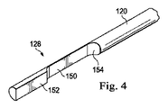
図3についてより詳細に言及すると、示されるように、遠位部分104は、本開示の一実施例による芯部材120及びフレキシブルな要素122を含む。示されように、芯部材120は、フレキシブルな要素122の外径126より小さい外径124を有する。幾つかの例において、フレキシブルな要素122の外径126は、血管内デバイス100の所望の外径と同じか又は実質的に同じである。従って、幾つかの特定の実施形態において、フレキシブルな要素122の外径126は、約0.014インチ(例えば、0.0138インチ〜0.0142インチ)である。フレキシブルな要素150は、コイル、ポリマーチュービング、コイルが埋め込まれたポリマーチュービング及び/又はその組み合わせであってもよい。その点で、フレキシブルな要素150は、幾つかの実装において複数の部品を有してもよい。図3においては示されないにもかかわらず、遠位部分104は、部品108(又は、部品108を含むハウジング)から血管内デバイス100の遠位先端105に遠位に延在する更なるフレキシブルな要素を含む。前と同じように、この遠位フレキシブルな要素は、コイル、ポリマーチュービング及び/又はコイルが埋め込まれたポリマーチュービングであってもよい。幾つかの例において、遠位のフレキシブルな要素は、放射線不透過性であり、及び/又は、放射線不透過性の先端を含む。幾つかの実装において、フローセンサは、血管内デバイス100の遠位先端105に配置される。概して、血管内デバイス100の遠位部分104は、上で参照により取り込まれる特許及び出願のいずれかにおいて述べられたものと同様の特徴を含み得るが、以下で述べられる本開示に関する遷移セクションを利用する。
Referring to FIG. 3 in more detail, as shown, the
芯部材120は、ステンレス鋼、ニッケル及びチタン合金(例えば、ニチノール及びNiTiCo)、ポリエーテルエーテルケトン、304Vステンレス鋼、MP35N又は他の金属又は重合材料のような、任意の適切な材料で形成され得る。以下で更に詳細に述べられるように、芯部材120の近位セクションは、芯部材120が中央部分102の芯部材130と結合されるのを可能にする係合構造128を含む。
The
また、図3に示されるように、中心部分102は、本開示の一実施形態による芯部材130及び外層132を含む。示されるように、芯部材120は、異なる形状を有する断面134及び断面136を含む。とりわけ、示された実施形態において、断面134及び136は、異なる外径を有する。その点で、断面136は、断面134の外径140より小さい外径138を有する。同様に、断面136の外径138は、外層132の外径142より小さい。幾つかの例において、外層132の外径142は、血管内デバイス100の所望の外径と同じか又は実質的に同じである。従って、幾つかの特定の実施形態において、外層132の外径142は、約0.014インチ(例えば、0.0138インチ〜0.0142インチ)である。
Also, as shown in FIG. 3, the
外層132は、ここに埋め込まれた導体を含む。以下で述べられるように、本開示の示された実施形態において、2つの導体は、中央部分102の外層132の範囲内に埋め込まれる。その点で、導体は、幾つかの例においてポリマーである外層132を形成する材料により完全にカプセル化される。幾つかの実施形態において、外層132の部分又は分離層のような絶縁層は、導体と芯部材130との間に形成される。そのため、絶縁層は、導体を芯部材130から電気的に隔離するために利用され得る。結果として、芯部材130及び/又は外層132に埋められた導体の各々は、血管内デバイス100の独立した電気通信経路として利用され得る。
The
埋め込まれた導体の各々は、伝導性材料(例えば、銅、金、銀、プラチナ又は他の適切な伝導性材料)で形成される。概して、導体のサイズは、導体が外層132を形成する材料内に完全に埋め込まれるのを可能にするように選択される。従って、幾つかの例において、導体は、24AWG導体と64AWG導体との間であり、幾つかの実施形態によれば、48AWG導体を利用する。他の例において、より大きな又はより小さな導体が利用される。特定の実施形態において、導体は、中央部分102の外周のまわりと実質的に同程度の空間である。しかしながら、導体は、任意の適切な態様において埋め込まれていてもよく、及び/又は、対称、非―対称、幾何学的及び非幾何学的パターンを含むパターンであってもよい。幾つかの例において、導体は、中心直径を最大にするコーティング壁厚の最適化及び接続の容易さを可能にする伝導性リボンである。
Each embedded conductor is formed of a conductive material (eg, copper, gold, silver, platinum or other suitable conductive material). In general, the size of the conductor is selected to allow the conductor to be completely embedded within the material forming the
芯部材130は、ステンレス鋼、ニッケル及びチタン合金(例えばニチノール及びNiTiCo)、ポリエーテルエーテルケトン、304Vステンレス鋼、MP35N又は他の金属若しくは重合材料のような、任意の適切な材料で形成され得る。芯部材130の遠位セクションは、芯部材130が遠位部分104の芯部材120と結合されるのを可能にする係合構造144を含む。概して、係合構造128及び144は、芯部材120及び130の間の物理的なインタフェースを提供するのに役立つ。その点で、係合構造128及び144は、芯部材120及び130の間の、トルクの転送、押圧力及び/又は牽引力を促進するために利用され得る。更に、係合構造128及び144は、一次元、二次元又は三次元において互いに対して芯部材120及び130の位置を調整するために利用され得る。従って、係合構造128及び144は、限定することなく、凸部、凹部、平面、先細、曲線/アーク、湾曲、ロッキングフィーチャ及び/又はその組み合わせを含む、斯様な配置を促進するために構造的な特徴の任意の組み合わせを含む。
The
図4〜図6を参照すると、本開示による係合構造128の態様が示される。本開示の示された実施形態において、係合構造128及び144は、同じ構造的特徴を有し、それ故、係合構造144は、別々には述べられないだろう。しかしながら、他の実施形態において、係合構造128及び144は、互いに嵌合するように構成される異なる構造的特徴を有する。示されるように、係合構造128は、互いからずらされる平面150及び平面152を含む。その点で、平面150には、平面150より大きな範囲に凹部が作られる。例えば、示された実施形態において、平面150は、芯部材120を通る経路の約33%に配置されるのに対し、平面152は、芯部材120を通る経路の約67%に配置される。また、係合構造128は、平面150と芯部材120の外面との間の遷移154を含む。同様に、係合構造128は、平面150と平面152との間の遷移156を含む。示された実施形態において、遷移154及び156は、湾曲されるか又は円弧形にされるが、他の例において、先細にされ、及び/又は、段のある形状にされる。幾つかの例において、係合構造128は、粉砕、エッチング、レーザ除去及び/又はその組み合わせのような適切な製造技術を利用して芯部材の部分を除去することにより、芯部材120において規定される。他の例において、係合構造128は、成形プロセスの部分として芯部材120において規定される。
With reference to FIGS. 4-6, aspects of an
図3を再度参照して、中央部分102を遠位部分104に結合するために、係合構造128及び144は互いに係合される。とりわけ、示されるように、係合構造128の平面150及び152は、係合構造144の対応する平面と係合される。更に、軸方向において所望の配置を提供するために、中央部分102及び遠位部分104は、係合構造128の遷移156が係合構造144の対応する遷移を係合するように、互いから離れるように引き戻され得る。結合構造128及び144を介して係合される芯部材120及び130によれば、チューブ状部材160は、芯部材120及び130の相対的位置を維持するのを支援するために、係合構造128及び144のまわりに配置され得る。チューブ状部材160は、限定することなく304Vステンレス鋼、ニチノール、NiTiCo及びポリイミドを含む、金属及びポリマーを含む任意の適切な材料で形成され得る。幾つかの例において、チューブ状部材160は、ハイポチューブである。はんだ又は接着剤は、芯部材120及び130を互いに及びチューブ状部材160に固定するためにチューブ状部材160の内部に流し込まれ得る。その点で、はんだ又は接着剤は、部品間の固体物理的接続を提供するために、芯部材120及び130間のギャップを埋め、チューブ状部材160内の芯部材120及び130を囲むだろう。
Referring again to FIG. 3, the
図8A及び図8Bに示されるように、チューブ状部材160は、係合構造128及び144が互いに係合するのを可能にするために係合構造128の遠位位置における芯部材120周辺に配置され得る。係合構造128及び144が係合されると、チューブ状部材160は、矢印162で示されるように、芯部材120に沿って係合される係合構造128及び144を囲む位置まで近位に移動され得る。係合構造128及び144周辺に配置されたチューブ状部材160によれば、芯部材120及び130は、接着剤及び/又ははんだを用いて一緒に接続され得る。上記したように、幾つかの例において、これらを一緒に結合するときに芯部材120及び130に(例えば、これらを引き戻すことにより)僅かな張力を与えることが有利である。チューブ状部材が係合構造144の近位の芯部材130周辺で開始し、そして、係合された係合構造128及び144を囲むように遠位に移動される場合に、同様のアプローチが利用され得ることに留意されたい。更に、芯部材120及び130は、係合構造周辺に配置されたチューブ状部材160を伴うことなく、はんだ、接着剤、溶接等により互いに固定され得ることが留意されるべきである。更に、幾つかの実施形態において、血管内デバイス100は、チューブ状部材160を含まないが、ジョイントを固めるために他の要素又は構造を含んでもよい。
As shown in FIGS. 8A and 8B, the
図9〜図13を参照すると、遠位部分104の電気導体170及び172は、中央部分102の外層132における埋め込まれた導体に電気的に結合されている。幾つかの実施形態において、絶縁層は、埋め込まれた導体への接続のためのチューブ状部材160並びに芯部材120及び130のさらされた部分に渡って電気導体170及び172を延在させる前に芯部材120及び130及びチューブ状部材160周辺に形成される。その点で、絶縁層は、導体170及び172から芯部材120及び130並びに筒状部材160を電気的に絶縁するのに役立つ。絶縁層は、任意の適切な材料で形成されてもよい。幾つかの例において、絶縁層は、ポリマー層である。幾つかの実装において、絶縁層は、パリレン層である。概して、絶縁層は、任意の適切な厚さを有してもよいが、幾つかの例において、約0.0001インチ〜約0.001インチの厚さを有する。幾つかの例において、導体170及び172は、芯部材120及び130並びにチューブ状部材160のまわりの絶縁層に加えて又はその代わりに、絶縁層でコーティングされる。
With reference to FIGS. 9-13, the
図10及び図11に示されるように、チューブ状部材160は、導体170及び172が血管内デバイス100の所望の外径を越えて遷移セクション114の外径を増大させることなくチューブ状部材160の外側に沿って延在するのを可能にするために平坦化された部分を含む。同様の理由のために、幾つかの例において、導体170及び172は、矩形の、卵形の、丸い矩形の形状、及び/又は、平坦化された形状を有する。図10に示されるように、導体170は、チューブ状部材160の平面174の長さ方向に延在し、接続176において中央部分102の埋め込まれた導体に電気的に結合される。導体170は、限定されるものではないがはんだ、物理的接触、電気カプラ等を含む任意の適切な技術を用いて埋め込まれた導体に電気的に結合され得る。同様に、図11に示されるように、導体172は、チューブ状部材160の平面178の長さ方向に延在し、接続180の中央部分102の埋め込まれた導体に電気的に結合される。導体172は、限定されるものではないがはんだ、物理的接触、電気カプラ等を含む任意の適切な技術を用いて埋め込まれた導体に電気的に結合され得る。
As shown in FIGS. 10 and 11, the
幾つかの実装において、埋め込まれた導体は、中央部分102の縦軸に沿った或る長さに対して埋め込まれた導体をカバーする外層132の一部を除去することにより導体170及び172への電気的結合のために露出される。幾つかの実装において、埋め込まれた導体は、中央部分102の縦軸に直交して延在する端面において導体170及び172への電気結合のために露出される。即ち、埋め込まれた導体は、中央部分の長さに沿って露出されないが、むしろ外層132の端面において露出される。図12は、平面174及び178を示すチューブ状部材160の斜視図を与える。図13は、チューブ状部材160に渡って延在する導体170及び172並びにチューブ状部材160の範囲内の芯部材120及び130の係合を示す遷移セクション114の側面図を与える。
In some implementations, the embedded conductor is transferred to
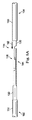
図14を参照すると、外層182は、導体170、172、チューブ状部材160並びに芯部材120及び130を介して形成される。示された実施形態において、外層182は、中央部分102と遠位部分104との間の血管内デバイス100に沿って距離184だけ延在する。示されるように、距離184は、中央部分102の外層132及び遠位部分104のフレキシブルな要素122の各々の部分及び遷移セクション114をカバーする外層182をもたらす。外層182は、他の例における遠位部分104及び/又は中央部分102のより大きな又はより小さな量及び/又は遷移セクション114のより小さな量をカバーしてもよい。外層182は、任意の適切な材料で形成され得る。幾つかの例において、外層182は、遷移セクション114を封止するように構成されるポリマー材料である。外層182は、幾つかの例においてPET収縮適合チュービングである。接着剤は、幾つかの実装において電気的接続のための適切な水分バリアを保証するためにPET収縮適合チュービング内に配置される。幾つかの例において、コーティングは、血管内デバイス100の少なくとも一部に設けられ、これは、遷移セクション114を含んでもよい。その点で、コーティングは、適切な親水性又は疎水性コーティングであり得る。幾つかの実装において、コーティングは、増大されたなめらかさを与える。例示的なコーティング材料としては、PTFEを含浸させたポリイミド、シリコーンベースのコーティング及び親水性ベースのコーティングが挙げられるが、これに限定されるものではない。概して、コーティングは、材料の極めて細い層であるだろう。例えば、幾つかの実装において、コーティングは、約0.0005インチより小さい、約0.0001インチをより小さい、及び/又は、約0.00005インチより小さい厚さを有する。
Referring to FIG. 14, the
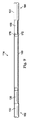
図15を参照すると、幾つかの例において、遷移セクション114は、チューブ状部材192及び/又はチューブ状部材190を含む。その点で、チューブ状部材190及び192は、芯部材120及び/又は130を囲むエリアにおいて遷移セクション114の直径を増大させるために利用され得る。その点において、チューブ状部材160が係合された係合構造128及び144周辺に配置されるチューブ状部材160の前に芯部材120及び130の係合を促進するために芯部材120に沿って移動するのを可能にするために、フレキシブルな要素122及びチューブ状部材160に対する低減された外径を有する芯部材120の一部は、フレキシブルな要素122とチューブ状部材160との間で露出されるだろう。同様に、チューブ状部材160及び外層132に対する低減された外径を有する芯部材130の一部は、チューブ状部材160と外層132との間で露出されてもよい。従って、チューブ状部材190及び192は、遷移セクション114の外径の全体的変動性を低減させるためにこれらのエリアにおいて直径を増大させるために利用されてもよい。幾つかの例において、チューブ状部材は、ポリマーチュービングである。幾つかの実装において、チュービングは、チューブ状部材160の位置決めの後、芯部材130に渡る位置決めを可能にするために分割される。幾つかの特定の実施形態において、チューブ状部材190及び192は、PET収縮適合チュービングである。幾つかの例において、チューブ状部材190及び192のうちの1つのみが利用される。
Referring to FIG. 15, in some examples, the
本開示のガイドワイヤは、センサにより受信される信号を圧力及び速度測定値に変換する計算デバイス(例えばラップトップ、デスクトップ又はタブレットコンピュータ)又は生理学モニタのような器具に接続され得る。器具は、更にCFR(Coronary Flow Reserve)及びFFR(Fractional Flow Reserve)を計算することができ、測定値及び計算結果をユーザインタフェースを介してユーザに提供することができる。幾つかの実施形態において、ユーザは、本開示の血管内デバイスにより取得されるデータに関連付けられる画像を表示するために視覚的インタフェースとインタラクトする。ユーザからの入力(例えばパラメータ又は選択)は、電子デバイスにおけるプロセッサにより受信される。前記選択は、可視ディスプレイにレンダリングされ得る。 The guidewire of the present disclosure can be connected to a computing device (eg, a laptop, desktop or tablet computer) or an instrument such as a physiological monitor that converts signals received by the sensor into pressure and velocity measurements. The instrument can further calculate CFR (Coronary Flow Reserve) and FFR (Fractional Flow Reserve), and can provide the measurement value and calculation result to the user via the user interface. In some embodiments, the user interacts with a visual interface to display an image associated with data acquired by the disclosed intravascular device. Input (eg, parameters or selections) from the user is received by a processor in the electronic device. The selection may be rendered on a visible display.
当業者は、前記の装置、システム及び方法が種々の手段において変更され得ることを認めるだろう。従って、当業者は、本開示により含まれる実施形態が前記の特定の例示的な実施形態に限定されるものではないと認識するだろう。その点で、例示的な実施形態が示されて述べられたにもかかわらず、広範囲の修正、変更及び置換が前述の開示において予測される。斯様なバリエーションは、本開示の要旨を逸脱しない範囲で前述のものに対して行われてもよいことが理解される。従って、添付の特許請求の範囲は広く、及び、本開示と一致した態様において解釈されることが適切である。 Those skilled in the art will appreciate that the above-described devices, systems and methods can be modified in various ways. Accordingly, those skilled in the art will recognize that the embodiments encompassed by this disclosure are not limited to the specific exemplary embodiments described above. In that regard, despite the exemplary embodiments shown and described, a wide range of modifications, changes and substitutions are anticipated in the foregoing disclosure. It will be understood that such variations may be made to the foregoing without departing from the scope of the present disclosure. Accordingly, it is appropriate that the appended claims be construed broadly and interpreted in a manner consistent with this disclosure.
Claims (39)
近位芯部材及び少なくとも1つの近位電気導体を有する近位部分を設けるステップであって、前記近位芯部材の遠位セクションは第1の係合構造を含む、ステップと、
遠位芯部材、センシング要素、及び、センシング要素に結合される少なくとも1つの遠位電気導体を有する遠位部分を設けるステップであって、前記遠位芯部材の近位セクションは第2の係合構造を含む、ステップと、
前記近位部分を前記遠位部分に結合するステップとを有し、
前記結合するステップは、
前記近位芯部材を前記遠位芯部材に固定するステップであって、前記近位芯部材を前記遠位芯部材に固定することは、前記第1の係合構造を第2の係合構造と係合させることを含む、ステップと、
前記少なくとも1つの近位電気導体が前記センシング要素と電気通信状態になるように、前記少なくとも1つの近位電気導体を前記少なくとも1つの遠位電気導体に電気的に結合するステップとを有する、方法。 A method of forming a sensing guidewire,
Providing a proximal portion having a proximal core member and at least one proximal electrical conductor, wherein the distal section of the proximal core member includes a first engagement structure;
Providing a distal core member, a sensing element, and a distal portion having at least one distal electrical conductor coupled to the sensing element, wherein the proximal section of the distal core member has a second engagement Including structure, steps;
Coupling the proximal portion to the distal portion;
The combining step includes
Securing the proximal core member to the distal core member, wherein the proximal core member is secured to the distal core member, the first engagement structure being a second engagement structure; Engaging with, and
Electrically coupling the at least one proximal electrical conductor to the at least one distal electrical conductor such that the at least one proximal electrical conductor is in electrical communication with the sensing element. .
前記少なくとも1つの遠位電気導体は、2つの導体を含み、
前記近位部分を前記遠位部分に結合することは、前記ハイポチューブの2つの平面に沿って前記2つの遠位電気導体を延在させることを含む、請求項7に記載の方法。 The hypotube includes two planes;
The at least one distal electrical conductor includes two conductors;
The method of claim 7, wherein coupling the proximal portion to the distal portion includes extending the two distal electrical conductors along two planes of the hypotube.
前記近位芯部材を前記遠位芯部材に固定することは、前記近位芯部材が前記センシング要素と電気通信状態になるように前記近位芯部材を前記遠位芯部材を電気的に結合することを含む、請求項9に記載の方法。 The distal core member is electrically coupled to the sensing element;
Fixing the proximal core member to the distal core member electrically couples the proximal core member to the distal core member such that the proximal core member is in electrical communication with the sensing element. 10. The method of claim 9, comprising:
前記近位部分に結合される遠位部分であって、前記遠位部分は、遠位芯部材、センシング要素、及び、前記センシング要素に結合される少なくとも1つの遠位電気導体を有する、遠位部分とを有し、
前記遠位芯部材の近位セクションは、前記第2の係合構造により前記近位芯部材の前記第1の係合構造に係合される第2の係合構造を含み、
前記少なくとも1つの遠位電気導体は、前記少なくとも1つの近位電気導体が前記センシング要素と電気通信状態になるように前記少なくとも1つの近位電気導体に結合される、センシングガイドワイヤ。 A proximal portion having a proximal core member and at least one proximal electrical conductor, wherein the distal section of the proximal core member includes a first engagement structure;
A distal portion coupled to the proximal portion, the distal portion having a distal core member, a sensing element, and at least one distal electrical conductor coupled to the sensing element And having a part
The proximal section of the distal core member includes a second engagement structure that is engaged by the second engagement structure with the first engagement structure of the proximal core member;
The sensing guidewire, wherein the at least one distal electrical conductor is coupled to the at least one proximal electrical conductor such that the at least one proximal electrical conductor is in electrical communication with the sensing element.
前記少なくとも1つの遠位電気導体は、2つの導体を含み、
前記2つの遠位電気導体は、前記ハイポチューブの2つの平面に沿って延在する、請求項27に記載のセンシングガイドワイヤ。 The hypotube includes two planes;
The at least one distal electrical conductor includes two conductors;
28. A sensing guidewire according to claim 27, wherein the two distal electrical conductors extend along two planes of the hypotube.
Applications Claiming Priority (3)
| Application Number | Priority Date | Filing Date | Title |
|---|---|---|---|
| US201461982080P | 2014-04-21 | 2014-04-21 | |
| US61/982,080 | 2014-04-21 | ||
| PCT/US2015/026643 WO2015164250A1 (en) | 2014-04-21 | 2015-04-20 | Intravascular devices, systems, and methods having separate sections with engaged core components |
Related Child Applications (1)
| Application Number | Title | Priority Date | Filing Date |
|---|---|---|---|
| JP2019163477A Division JP6826172B2 (en) | 2014-04-21 | 2019-09-09 | Intravascular devices, systems and methods with separate sections with core elements to be engaged |
Publications (3)
| Publication Number | Publication Date |
|---|---|
| JP2017513604A true JP2017513604A (en) | 2017-06-01 |
| JP2017513604A5 JP2017513604A5 (en) | 2018-06-07 |
| JP6586425B2 JP6586425B2 (en) | 2019-10-02 |
Family
ID=54320931
Family Applications (3)
| Application Number | Title | Priority Date | Filing Date |
|---|---|---|---|
| JP2016563781A Active JP6586425B2 (en) | 2014-04-21 | 2015-04-20 | Intravascular device, system and method having separate sections with core elements engaged |
| JP2019163477A Active JP6826172B2 (en) | 2014-04-21 | 2019-09-09 | Intravascular devices, systems and methods with separate sections with core elements to be engaged |
| JP2021004174A Active JP7216123B2 (en) | 2014-04-21 | 2021-01-14 | Intravascular device, system and method having separate sections with engaged core elements |
Family Applications After (2)
| Application Number | Title | Priority Date | Filing Date |
|---|---|---|---|
| JP2019163477A Active JP6826172B2 (en) | 2014-04-21 | 2019-09-09 | Intravascular devices, systems and methods with separate sections with core elements to be engaged |
| JP2021004174A Active JP7216123B2 (en) | 2014-04-21 | 2021-01-14 | Intravascular device, system and method having separate sections with engaged core elements |
Country Status (5)
| Country | Link |
|---|---|
| US (2) | US10772564B2 (en) |
| EP (1) | EP3133987B1 (en) |
| JP (3) | JP6586425B2 (en) |
| CN (1) | CN106231999B (en) |
| WO (1) | WO2015164250A1 (en) |
Cited By (3)
| Publication number | Priority date | Publication date | Assignee | Title |
|---|---|---|---|---|
| WO2020016986A1 (en) | 2018-07-19 | 2020-01-23 | 朝日インテック株式会社 | Guide wire and guide wire manufacturing method |
| JP2020531151A (en) * | 2017-08-31 | 2020-11-05 | コーニンクレッカ フィリップス エヌ ヴェKoninklijke Philips N.V. | Sensing guide wire with integrated proximal locking features |
| WO2022264669A1 (en) * | 2021-06-14 | 2022-12-22 | 朝日インテック株式会社 | Guide wire |
Families Citing this family (6)
| Publication number | Priority date | Publication date | Assignee | Title |
|---|---|---|---|---|
| US9624095B2 (en) * | 2012-12-28 | 2017-04-18 | Volcano Corporation | Capacitive intravascular pressure-sensing devices and associated systems and methods |
| EP3133987B1 (en) * | 2014-04-21 | 2019-09-11 | Koninklijke Philips N.V. | Sensing guide wire and method of manufacturing thereof |
| CN106691506A (en) * | 2016-12-29 | 2017-05-24 | 天津恒宇医疗科技有限公司 | OCT imaging conduit with high imaging quality |
| US11406416B2 (en) * | 2018-10-02 | 2022-08-09 | Neuravi Limited | Joint assembly for vasculature obstruction capture device |
| US20210178127A1 (en) * | 2019-12-16 | 2021-06-17 | Stryker Corporation | Guidewires for medical devices |
| WO2021249936A1 (en) | 2020-06-09 | 2021-12-16 | Philips Image Guided Therapy Corporation | Physiology sensing intraluminal device with reibling method |
Citations (5)
| Publication number | Priority date | Publication date | Assignee | Title |
|---|---|---|---|---|
| JPH11508160A (en) * | 1995-06-22 | 1999-07-21 | ラディ・メディカル・システムズ・アクチェボラーグ | Sensor / guide device |
| JP2003527169A (en) * | 1999-12-30 | 2003-09-16 | アドバンスド、カーディオバスキュラー、システムズ、インコーポレーテッド | Guide wire with vibration damping mechanism |
| JP2005514115A (en) * | 2001-12-27 | 2005-05-19 | アドバンスド、カーディオバスキュラー、システムズ、インコーポレーテッド | Apparatus and method for joining two guidewire core materials without hypotube |
| US20110166519A1 (en) * | 2010-01-04 | 2011-07-07 | Tyco Healthcare Group, L.P. | Apparatus and methods for treating hollow anatomical structures |
| US20150297138A1 (en) * | 2014-04-21 | 2015-10-22 | Koninklijke Philips N.V. | Intravascular devices, systems, and methods having separate sections with engaged core components |
Family Cites Families (45)
| Publication number | Priority date | Publication date | Assignee | Title |
|---|---|---|---|---|
| US4691709A (en) | 1986-07-01 | 1987-09-08 | Cordis Corporation | Apparatus for measuring velocity of blood flow in a blood vessel |
| US4958642A (en) * | 1988-11-02 | 1990-09-25 | Cardiometrics, Inc. | Guide wire assembly with electrical functions and male and female connectors for use therewith |
| US5240437A (en) * | 1988-11-02 | 1993-08-31 | Cardiometrics, Inc. | Torqueable guide wire assembly with electrical functions, male and female connectors for use therewith and system and apparatus for utilizing the same |
| US5125137A (en) | 1990-09-06 | 1992-06-30 | Cardiometrics, Inc. | Method for providing a miniature ultrasound high efficiency transducer assembly |
| US5873835A (en) | 1993-04-29 | 1999-02-23 | Scimed Life Systems, Inc. | Intravascular pressure and flow sensor |
| WO1996007351A1 (en) * | 1994-09-02 | 1996-03-14 | Cardiometrics, Inc. | Ultra miniature pressure sensor and guidewire using the same and method |
| US6350266B1 (en) * | 1995-02-02 | 2002-02-26 | Scimed Life Systems, Inc. | Hybrid stone retrieval device |
| US6090052A (en) * | 1997-03-25 | 2000-07-18 | Radi Medical Systems Ab | Guide wire having a male connector |
| US5980471A (en) * | 1997-10-10 | 1999-11-09 | Advanced Cardiovascular System, Inc. | Guidewire with tubular connector |
| US6090050A (en) | 1998-07-16 | 2000-07-18 | Salix Medical, Inc. | Thermometric apparatus and method |
| AU3187900A (en) | 1999-03-09 | 2000-09-28 | Florence Medical Ltd. | A method and system for pressure based measurements of cfr and additional clinical hemodynamic parameters |
| WO2001013779A2 (en) | 1999-08-25 | 2001-03-01 | Florence Medical Ltd. | A method and system for stenosis identification, localization and characterization using pressure measurements |
| US6354999B1 (en) | 2000-01-14 | 2002-03-12 | Florence Medical Ltd. | System and method for detecting, localizing, and characterizing occlusions and aneurysms in a vessel |
| US6551250B2 (en) | 2001-03-29 | 2003-04-22 | Hassan Khalil | Transit time thermodilution guidewire system for measuring coronary flow velocity |
| EP1432467B1 (en) * | 2001-10-05 | 2005-12-14 | Boston Scientific Limited | Composite guidewire |
| US7134994B2 (en) | 2002-05-20 | 2006-11-14 | Volcano Corporation | Multipurpose host system for invasive cardiovascular diagnostic measurement acquisition and display |
| US20060106321A1 (en) | 2003-01-16 | 2006-05-18 | Galil Medical Ltd. | Device, system, and method for detecting, localizing, and characterizing plaque-induced stenosis of a blood vessel |
| US20040176683A1 (en) | 2003-03-07 | 2004-09-09 | Katherine Whitin | Method and apparatus for tracking insertion depth |
| US6993974B2 (en) * | 2003-07-02 | 2006-02-07 | Radi Medical Systems Ab | Sensor and guide wire assembly |
| US7998090B2 (en) * | 2004-08-31 | 2011-08-16 | Abbott Cardiovascular Systems Inc. | Guide wire with core having welded wire segments |
| SE0402145D0 (en) | 2004-09-08 | 2004-09-08 | Radi Medical Systems | Pressure measurement system |
| US8277386B2 (en) | 2004-09-27 | 2012-10-02 | Volcano Corporation | Combination sensor guidewire and methods of use |
| US7799019B2 (en) * | 2005-05-10 | 2010-09-21 | Vivant Medical, Inc. | Reinforced high strength microwave antenna |
| EP1933715A4 (en) | 2005-10-14 | 2012-08-29 | Cleveland Clinic Foundation | System and method for characterizing vascular tissue |
| US20070255145A1 (en) * | 2006-04-28 | 2007-11-01 | Radi Medical Systems Ab | Sensor and guide wire assembly |
| WO2007145751A2 (en) * | 2006-05-12 | 2007-12-21 | Concert Medical Llc | Guidewire formed with composite construction and method for making the same |
| US20080077050A1 (en) * | 2006-09-08 | 2008-03-27 | Radi Medical Systems Ab | Electrical connector for medical device |
| US20080139951A1 (en) | 2006-12-08 | 2008-06-12 | Cardiac Pacemakers, Inc. | Detection of Stenosis |
| US8298156B2 (en) | 2008-09-11 | 2012-10-30 | Acist Medical Systems, Inc. | Physiological sensor delivery device and method |
| EP3520689A1 (en) | 2009-09-18 | 2019-08-07 | St. Jude Medical Coordination Center BVBA | System for acquiring physiological variables measured in a body |
| JP2011166519A (en) | 2010-02-10 | 2011-08-25 | Seiko Epson Corp | Radio tag, management apparatus, and energy-saving system |
| WO2012061935A1 (en) * | 2010-11-09 | 2012-05-18 | Opsens Inc. | Guidewire with internal pressure sensor |
| US20120172905A1 (en) * | 2010-12-30 | 2012-07-05 | Kimberly-Clark, Inc. | Tissue Removal Apparatus and Method of Manufacturing Same |
| GB201100137D0 (en) | 2011-01-06 | 2011-02-23 | Davies Helen C S | Apparatus and method of assessing a narrowing in a fluid tube |
| GB201100136D0 (en) | 2011-01-06 | 2011-02-23 | Davies Helen C S | Apparatus and method of characterising a narrowing in a filled tube |
| WO2012109039A1 (en) * | 2011-01-30 | 2012-08-16 | Warnking Reinhard J | System for detection of blood pressure using a pressure sensing guide wire |
| WO2013028612A2 (en) | 2011-08-20 | 2013-02-28 | Volcano Corporation | Devices, systems, and methods for visually depicting a vessel and evaluating treatment options |
| WO2013082032A1 (en) * | 2011-11-28 | 2013-06-06 | Mazar Scott T | Steerable guide wire with pressure sensor |
| US9364640B2 (en) * | 2012-05-07 | 2016-06-14 | St. Jude Medical Atrial Fibrillation Division, Inc. | Medical device guidewire with helical cutout and coating |
| US9351687B2 (en) | 2012-06-28 | 2016-05-31 | Volcano Corporation | Intravascular devices, systems, and methods |
| EP2900150B1 (en) * | 2012-09-29 | 2018-04-18 | Mitralign, Inc. | Plication lock delivery system |
| WO2014100458A1 (en) | 2012-12-21 | 2014-06-26 | Volcano Corporation | Mounting structures for components of intravascular devices |
| US20140187980A1 (en) | 2012-12-28 | 2014-07-03 | Volcano Corporation | Hypotube Sensor Mount for Sensored Guidewire |
| US20140187984A1 (en) | 2012-12-31 | 2014-07-03 | Volcano Corporation | In-Wall Hypotube Sensor Mount for Sensored Guidewire |
| US10791991B2 (en) | 2012-12-31 | 2020-10-06 | Philips Image Guided Therapy Corporation | Intravascular devices, systems, and methods |
-
2015
- 2015-04-20 EP EP15783695.8A patent/EP3133987B1/en active Active
- 2015-04-20 WO PCT/US2015/026643 patent/WO2015164250A1/en active Application Filing
- 2015-04-20 CN CN201580020953.7A patent/CN106231999B/en active Active
- 2015-04-20 JP JP2016563781A patent/JP6586425B2/en active Active
- 2015-04-21 US US14/692,443 patent/US10772564B2/en active Active
-
2019
- 2019-09-09 JP JP2019163477A patent/JP6826172B2/en active Active
-
2020
- 2020-09-14 US US17/019,506 patent/US11864918B2/en active Active
-
2021
- 2021-01-14 JP JP2021004174A patent/JP7216123B2/en active Active
Patent Citations (5)
| Publication number | Priority date | Publication date | Assignee | Title |
|---|---|---|---|---|
| JPH11508160A (en) * | 1995-06-22 | 1999-07-21 | ラディ・メディカル・システムズ・アクチェボラーグ | Sensor / guide device |
| JP2003527169A (en) * | 1999-12-30 | 2003-09-16 | アドバンスド、カーディオバスキュラー、システムズ、インコーポレーテッド | Guide wire with vibration damping mechanism |
| JP2005514115A (en) * | 2001-12-27 | 2005-05-19 | アドバンスド、カーディオバスキュラー、システムズ、インコーポレーテッド | Apparatus and method for joining two guidewire core materials without hypotube |
| US20110166519A1 (en) * | 2010-01-04 | 2011-07-07 | Tyco Healthcare Group, L.P. | Apparatus and methods for treating hollow anatomical structures |
| US20150297138A1 (en) * | 2014-04-21 | 2015-10-22 | Koninklijke Philips N.V. | Intravascular devices, systems, and methods having separate sections with engaged core components |
Cited By (5)
| Publication number | Priority date | Publication date | Assignee | Title |
|---|---|---|---|---|
| JP2020531151A (en) * | 2017-08-31 | 2020-11-05 | コーニンクレッカ フィリップス エヌ ヴェKoninklijke Philips N.V. | Sensing guide wire with integrated proximal locking features |
| JP7372907B2 (en) | 2017-08-31 | 2023-11-01 | コーニンクレッカ フィリップス エヌ ヴェ | Sensing guidewire with integrated proximal locking feature |
| WO2020016986A1 (en) | 2018-07-19 | 2020-01-23 | 朝日インテック株式会社 | Guide wire and guide wire manufacturing method |
| JPWO2020016986A1 (en) * | 2018-07-19 | 2021-06-24 | 朝日インテック株式会社 | Guide wire and method of manufacturing guide wire |
| WO2022264669A1 (en) * | 2021-06-14 | 2022-12-22 | 朝日インテック株式会社 | Guide wire |
Also Published As
| Publication number | Publication date |
|---|---|
| JP2020000914A (en) | 2020-01-09 |
| US20200405238A1 (en) | 2020-12-31 |
| JP6586425B2 (en) | 2019-10-02 |
| EP3133987B1 (en) | 2019-09-11 |
| WO2015164250A1 (en) | 2015-10-29 |
| JP7216123B2 (en) | 2023-01-31 |
| JP6826172B2 (en) | 2021-02-03 |
| CN106231999B (en) | 2020-01-21 |
| EP3133987A4 (en) | 2017-04-26 |
| JP2021062253A (en) | 2021-04-22 |
| CN106231999A (en) | 2016-12-14 |
| US10772564B2 (en) | 2020-09-15 |
| US20150297138A1 (en) | 2015-10-22 |
| US11864918B2 (en) | 2024-01-09 |
| EP3133987A1 (en) | 2017-03-01 |
Similar Documents
| Publication | Publication Date | Title |
|---|---|---|
| US11324410B2 (en) | Intravascular devices, systems, and methods having a core wire with embedded conductors | |
| JP6826172B2 (en) | Intravascular devices, systems and methods with separate sections with core elements to be engaged | |
| JP6945451B2 (en) | Intravascular devices, systems and methods with a polymer jacket formed around a communication line wrapped around a core member. | |
| US10441754B2 (en) | Intravascular devices, systems, and methods having a core wire formed of multiple materials | |
| JP6509117B2 (en) | Mounting structure for components of intravascular devices | |
| JP6568056B2 (en) | Intravascular device, system, and method | |
| JP2017533735A (en) | Intravascular devices, systems and methods having distal tip elements filled with adhesive | |
| US9603570B2 (en) | Intravascular devices, systems, and methods having a sensing element embedded in adhesive | |
| JP2015521917A (en) | Intravascular device connection structure and related systems and methods | |
| JP6882995B2 (en) | Intravascular devices, systems and methods using adhesively attached molded ribbons | |
| US20180184981A1 (en) | Intravascular devices systems and methods with a solid core proximal section and a slotted tubular distal section |
Legal Events
| Date | Code | Title | Description |
|---|---|---|---|
| RD04 | Notification of resignation of power of attorney |
Free format text: JAPANESE INTERMEDIATE CODE: A7424 Effective date: 20170214 |
|
| A521 | Request for written amendment filed |
Free format text: JAPANESE INTERMEDIATE CODE: A523 Effective date: 20180416 |
|
| A621 | Written request for application examination |
Free format text: JAPANESE INTERMEDIATE CODE: A621 Effective date: 20180416 |
|
| A977 | Report on retrieval |
Free format text: JAPANESE INTERMEDIATE CODE: A971007 Effective date: 20190131 |
|
| A131 | Notification of reasons for refusal |
Free format text: JAPANESE INTERMEDIATE CODE: A131 Effective date: 20190226 |
|
| A521 | Request for written amendment filed |
Free format text: JAPANESE INTERMEDIATE CODE: A523 Effective date: 20190516 |
|
| TRDD | Decision of grant or rejection written | ||
| A01 | Written decision to grant a patent or to grant a registration (utility model) |
Free format text: JAPANESE INTERMEDIATE CODE: A01 Effective date: 20190820 |
|
| A61 | First payment of annual fees (during grant procedure) |
Free format text: JAPANESE INTERMEDIATE CODE: A61 Effective date: 20190909 |
|
| R150 | Certificate of patent or registration of utility model |
Ref document number: 6586425 Country of ref document: JP Free format text: JAPANESE INTERMEDIATE CODE: R150 |
|
| R250 | Receipt of annual fees |
Free format text: JAPANESE INTERMEDIATE CODE: R250 |
|
| R250 | Receipt of annual fees |
Free format text: JAPANESE INTERMEDIATE CODE: R250 |