EP3133987B1 - Sensing guide wire and method of manufacturing thereof - Google Patents
Sensing guide wire and method of manufacturing thereof Download PDFInfo
- Publication number
- EP3133987B1 EP3133987B1 EP15783695.8A EP15783695A EP3133987B1 EP 3133987 B1 EP3133987 B1 EP 3133987B1 EP 15783695 A EP15783695 A EP 15783695A EP 3133987 B1 EP3133987 B1 EP 3133987B1
- Authority
- EP
- European Patent Office
- Prior art keywords
- distal
- proximal
- core member
- guide wire
- electrical conductor
- Prior art date
- Legal status (The legal status is an assumption and is not a legal conclusion. Google has not performed a legal analysis and makes no representation as to the accuracy of the status listed.)
- Active
Links
Images


Classifications
-
- A—HUMAN NECESSITIES
- A61—MEDICAL OR VETERINARY SCIENCE; HYGIENE
- A61B—DIAGNOSIS; SURGERY; IDENTIFICATION
- A61B5/00—Measuring for diagnostic purposes; Identification of persons
- A61B5/68—Arrangements of detecting, measuring or recording means, e.g. sensors, in relation to patient
- A61B5/6846—Arrangements of detecting, measuring or recording means, e.g. sensors, in relation to patient specially adapted to be brought in contact with an internal body part, i.e. invasive
- A61B5/6847—Arrangements of detecting, measuring or recording means, e.g. sensors, in relation to patient specially adapted to be brought in contact with an internal body part, i.e. invasive mounted on an invasive device
- A61B5/6851—Guide wires
-
- A—HUMAN NECESSITIES
- A61—MEDICAL OR VETERINARY SCIENCE; HYGIENE
- A61B—DIAGNOSIS; SURGERY; IDENTIFICATION
- A61B5/00—Measuring for diagnostic purposes; Identification of persons
- A61B5/02—Detecting, measuring or recording pulse, heart rate, blood pressure or blood flow; Combined pulse/heart-rate/blood pressure determination; Evaluating a cardiovascular condition not otherwise provided for, e.g. using combinations of techniques provided for in this group with electrocardiography or electroauscultation; Heart catheters for measuring blood pressure
- A61B5/021—Measuring pressure in heart or blood vessels
- A61B5/0215—Measuring pressure in heart or blood vessels by means inserted into the body
-
- A—HUMAN NECESSITIES
- A61—MEDICAL OR VETERINARY SCIENCE; HYGIENE
- A61B—DIAGNOSIS; SURGERY; IDENTIFICATION
- A61B5/00—Measuring for diagnostic purposes; Identification of persons
- A61B5/02—Detecting, measuring or recording pulse, heart rate, blood pressure or blood flow; Combined pulse/heart-rate/blood pressure determination; Evaluating a cardiovascular condition not otherwise provided for, e.g. using combinations of techniques provided for in this group with electrocardiography or electroauscultation; Heart catheters for measuring blood pressure
- A61B5/026—Measuring blood flow
- A61B5/0265—Measuring blood flow using electromagnetic means, e.g. electromagnetic flowmeter
- A61B5/027—Measuring blood flow using electromagnetic means, e.g. electromagnetic flowmeter using catheters
-
- A—HUMAN NECESSITIES
- A61—MEDICAL OR VETERINARY SCIENCE; HYGIENE
- A61B—DIAGNOSIS; SURGERY; IDENTIFICATION
- A61B2562/00—Details of sensors; Constructional details of sensor housings or probes; Accessories for sensors
- A61B2562/12—Manufacturing methods specially adapted for producing sensors for in-vivo measurements
-
- A—HUMAN NECESSITIES
- A61—MEDICAL OR VETERINARY SCIENCE; HYGIENE
- A61B—DIAGNOSIS; SURGERY; IDENTIFICATION
- A61B2562/00—Details of sensors; Constructional details of sensor housings or probes; Accessories for sensors
- A61B2562/22—Arrangements of medical sensors with cables or leads; Connectors or couplings specifically adapted for medical sensors
- A61B2562/225—Connectors or couplings
- A61B2562/227—Sensors with electrical connectors
Definitions
- the present disclosure relates to intravascular devices, systems, and methods.
- the intravascular devices are guide wires that include separate sections with engaged core components.
- Heart disease is very serious and often requires emergency operations to save lives.
- a main cause of heart disease is the accumulation of plaque inside the blood vessels, which eventually occludes the blood vessels.
- Common treatment options available to open up the occluded vessel include balloon angioplasty, rotational atherectomy, and intravascular stents.
- surgeons have relied on X-ray fluoroscopic images that are planar images showing the external shape of the silhouette of the lumen of blood vessels to guide treatment.
- X-ray fluoroscopic images there is a great deal of uncertainty about the exact extent and orientation of the stenosis responsible for the occlusion, making it difficult to find the exact location of the stenosis.
- restenosis can occur at the same place, it is difficult to check the condition inside the vessels after surgery with X-ray.
- FFR fractional flow reserve
- intravascular catheters and guide wires are utilized to measure the pressure within the blood vessel, visualize the inner lumen of the blood vessel, and/or otherwise obtain data related to the blood vessel.
- guide wires containing pressure sensors, imaging elements, and/or other electronic, optical, or electro-optical components have suffered from reduced performance characteristics compared to standard guide wires that do not contain such components.
- the handling performance of previous guide wires containing electronic components have been hampered, in some instances, by the limited space available for the core wire after accounting for the space needed for the conductors or communication lines of the electronic component(s), the stiffness of the rigid housing containing the electronic component(s), and/or other limitations associated with providing the functionality of the electronic components in the limited space available within a guide wire.
- the proximal connector portion of the guide wire i.e ., the connector(s) that facilitate communication between the electronic component(s) of the guide wire and an associated controller or processor
- the proximal connector portion of the guide wire is fragile and prone to kinking, which can destroy the functionality of the guide wire. For this reason, surgeons are reluctant to remove the proximal connector from the guide wire during a procedure for fear of breaking the guide wire when reattaching the proximal connector. Having the guide wire coupled to the proximal connector further limits the maneuverability and handling of the guide wire.
- a problem with existing pressure and flow guide wires is that they require a complex assembly of many discrete components. That complex assembly process has limitations on design performance of the guide wire.
- the use of separate conductive wires running down the length of the wire reduces the space available for more supportive cores and can result in numerous issues during use due to poor solder joints with conductive bands, electrical shorts due to insulation issues, and breakage of the delicate conductive wires.
- US 5 240 437 A refers to a guide wire assembly comprising a guide wire with first and second conductors which extend along the length thereof.
- the guide wire also comprises a flexible cable having first and second conductors which extend along the length thereof.
- the connector assembly includes a male connector with a sleeve and a conductive core which is mounted in the sleeve.
- US 6,290,656 B1 A refers to a guide wire having a damped force vibration mechanism which isolates vibrations or shockwaves which otherwise would be transmitted along the length of the guide wire to its distal end. The damped force vibration mechanism helps absorb some of the energy created during the exchange of a delivery catheter or an interventional device on the guide wire or any shock or force generated from an external source.
- WO 2007/145751 A2 refers to a composite guidewire comprising a proximal wire segment having a proximal end, a distal end and a longitudinal axis extending between the proximal end and the distal end, the distal end of the proximal wire segment being formed with a first flat planar bonding face which extends parallel to the longitudinal axis, the proximal wire segment having a first elasticity and means for joining together two different wire segments at a joint that provides improved (i) tensile strength, (ii) torque strength, (iii) bending moment performance, and (iv) failure mode characteristics, among other things, and which is suitable for medical applications.
- the present disclosure is directed to intravascular devices, systems, and methods that include a guide wire having a separate sections coupled together by engaging core components.
- the present disclosure provides a more robust sensing guide wire that avoids the assembly and performance issues of prior sensing guide wires.
- Guide wires of the present disclosure have one or more transition sections that facilitate coupling of different portions of the guide wire.
- Any type of sensor can be connected to guide wires of the present disclosure. In certain embodiments, only a single sensor is connected to the guide wire. In other embodiments, multiple sensors are connected to the guide wire. All of the sensors may be the same. Alternatively, the sensors may differ from each other and measure different characteristics inside a vessel. Exemplary sensors are pressure, flow, and temperature sensors. Generally, any type of pressure sensor may be used with the guide wires of the present disclosure, including piezoresistive, optical and/or combinations thereof.
- the pressure sensor includes a crystalline semi-conductor material.
- any type of flow sensor may be used with guide wires of the present disclosure.
- the flow sensor includes an ultrasound transducer, such as a Doppler ultrasound transducer.
- the guide wire can include both a pressure sensor and a flow sensor.
- the methods can include providing a proximal portion having a proximal core member and at least one proximal electrical conductor, wherein a distal section of the proximal core member includes a first engagement structure; providing a distal portion having a distal core member, a sensing element, and at least one distal electrical conductor coupled to the sensing element, wherein a proximal section of the distal core member includes a second engagement structure; and coupling the proximal portion to the distal portion, including: securing the proximal core member to the distal core member, wherein securing the proximal core member to the distal core member includes engaging the first engagement structure with the second engagement structure; and electrically coupling the at least one proximal electrical conductor to the at least one distal electrical conductor such that the at least one proximal electrical conductor is in electrical communication with the sensing element.
- sensing guide wires are provided.
- the guide wires can include a proximal portion having a proximal core member and at least one proximal electrical conductor and a distal portion coupled to the proximal portion, the distal portion having a distal core member, a sensing element, and at least one distal electrical conductor coupled to the sensing element, wherein engagement structures of the proximal and distal core members are engaged and wherein the at least one distal electrical conductor is coupled to the at least one proximal electrical conductor such that the at least one proximal electrical conductor is in electrical communication with the sensing element.
- Another aspect of the present disclosure provides methods for measuring a characteristic inside a vessel.
- the methods can include providing a sensing guide wire in accordance with the present disclosure, inserting the guide wire into a vessel, and utilizing one or more sensing elements of the guide wire to measure one or more characteristics inside the vessel.
- flexible elongate member or “elongate flexible member” includes at least any thin, long, flexible structure that can be inserted into the vasculature of a patient. While the illustrated embodiments of the "flexible elongate members" of the present disclosure have a cylindrical profile with a circular cross-sectional profile that defines an outer diameter of the flexible elongate member, in other instances all or a portion of the flexible elongate members may have other geometric cross-sectional profiles (e.g ., oval, rectangular, square, elliptical, etc.) or non-geometric cross-sectional profiles.
- Flexible elongate members include, for example, guide wires and catheters. In that regard, catheters may or may not include a lumen extending along its length for receiving and/or guiding other instruments. If the catheter includes a lumen, the lumen may be centered or offset with respect to the cross-sectional profile of the device.
- the flexible elongate members of the present disclosure include one or more electronic, optical, or electro-optical components.
- a flexible elongate member may include one or more of the following types of components: a pressure sensor, a flow sensor, a temperature sensor, an imaging element, an optical fiber, an ultrasound transducer, a reflector, a mirror, a prism, an ablation element, an RF electrode, a conductor, and/or combinations thereof.
- these components are configured to obtain data related to a vessel or other portion of the anatomy in which the flexible elongate member is disposed.
- the components are also configured to communicate the data to an external device for processing and/or display.
- embodiments of the present disclosure include imaging devices for imaging within the lumen of a vessel, including both medical and non-medical applications.
- imaging devices for imaging within the lumen of a vessel, including both medical and non-medical applications.
- some embodiments of the present disclosure are particularly suited for use in the context of human vasculature. Imaging of the intravascular space, particularly the interior walls of human vasculature can be accomplished by a number of different techniques, including ultrasound (often referred to as intravascular ultrasound (“IVUS”) and intracardiac echocardiography (“ICE”)) and optical coherence tomography (“OCT”).
- IVUS intravascular ultrasound
- ICE intracardiac echocardiography
- OCT optical coherence tomography
- infrared, thermal, or other imaging modalities are utilized.
- distal portion of the flexible elongate member includes any portion of the flexible elongate member from the mid-point to the distal tip.
- flexible elongate members can be solid, some embodiments of the present disclosure will include a housing portion at the distal portion for receiving the electronic components.
- housing portions can be tubular structures attached to the distal portion of the elongate member.
- Some flexible elongate members are tubular and have one or more lumens in which the electronic components can be positioned within the distal portion.
- the electronic, optical, and/or electro-optical components and the associated communication lines are sized and shaped to allow for the diameter of the flexible elongate member to be very small.
- the outside diameter of the elongate member, such as a guide wire or catheter, containing one or more electronic, optical, and/or electro-optical components as described herein are between about 0.0007" (0.0178 mm) and about 0.118" (3.0 mm), with some particular embodiments having outer diameters of approximately 0.014" (0.3556 mm), approximately 0.018" (0.4572 mm), and approximately .035" (.889mm).
- the flexible elongate members incorporating the electronic, optical, and/or electro-optical component(s) of the present application are suitable for use in a wide variety of lumens within a human patient besides those that are part or immediately surround the heart, including veins and arteries of the extremities, renal arteries, blood vessels in and around the brain, and other lumens.
- Connected and variations thereof as used herein includes direct connections, such as being glued or otherwise fastened directly to, on, within, etc. another element, as well as indirect connections where one or more elements are disposed between the connected elements.
- “Secured” and variations thereof as used herein includes methods by which an element is directly secured to another element, such as being glued or otherwise fastened directly to, on, within, etc. another element, as well as indirect techniques of securing two elements together where one or more elements are disposed between the secured elements.
- the intravascular device 100 includes a flexible elongate member having a central portion 102, a distal portion 104 adjacent a distal end 105, and a proximal portion 106 adjacent a proximal end 107.
- a component 108 is positioned within the distal portion 104 proximal of the distal tip 105.
- the component 108 is representative of one or more electronic, optical, or electro-optical components.
- the component 108 is a pressure sensor, a flow sensor, a temperature sensor, an imaging element, an optical fiber, an ultrasound transducer, a reflector, a mirror, a prism, an ablation element, an RF electrode, a conductor, and/or combinations thereof.
- the specific type of component or combination of components can be selected based on an intended use of the intravascular device.
- the component 108 is positioned less than 10 cm, less than 5, or less than 3 cm from the distal tip 105.
- the component 108 is positioned within a housing of the flexible elongate member 102.
- the housing is a separate component secured to other components of the distal portion 104 in some instances.
- the housing is integrally formed as a part of a component of the distal portion 104.
- the intravascular device 100 also includes a connector 110 adjacent the proximal portion 106 of the device.
- the connector 110 is spaced from the proximal end 107 of the intravascular device 100 by a distance 112.
- the distance 112 is between 0% and 50% of the total length of the intravascular device 100.
- the total length of the intravascular device can be any length, in some embodiments the total length is between about 1300 mm and about 4000 mm, with some specific embodiments have a length of 1400 mm, 1900 mm, and 3000 mm.
- the connector 110 is positioned at the proximal end 107. In other instances, the connector 110 is spaced from the proximal end 107.
- the connector 110 is spaced from the proximal end 107 between about 0 mm and about 1400 mm. In some specific embodiments, the connector 110 is spaced from the proximal end by a distance of 0 mm, 300 mm, and 1400 mm.
- the connector 110 is configured to facilitate communication between the intravascular device 100 and another device. More specifically, in some embodiments the connector 110 is configured to facilitate communication of data obtained by the component 108 to another device, such as a computing device or processor. Accordingly, in some embodiments the connector 110 is an electrical connector. In such instances, the connector 110 provides an electrical connection to one or more electrical conductors that extend along the length of the flexible elongate member 102 and are electrically coupled to the component 108. In other embodiments, the connector 110 is an optical connector. In such instances, the connector 110 provides an optical connection to one or more optical communication pathways (e.g., fiber optic cable) that extend along the length of the flexible elongate member 102 and are optically coupled to the component 108.
- optical communication pathways e.g., fiber optic cable
- the connector 110 provides both electrical and optical connections to both electrical conductor(s) and optical communication pathway(s) coupled to the component 108.
- component 108 is comprised of a plurality of elements in some instances.
- the connector 110 is configured to provide a physical connection to another device, either directly or indirectly.
- the connector 110 is configured to facilitate wireless communication between the intravascular device 100 and another device.
- any current or future developed wireless protocol(s) may be utilized.
- the connector 110 facilitates both physical and wireless connection to another device.
- the connector 110 provides a connection between the component 108 of the intravascular device 100 and an external device.
- one or more electrical conductors, one or more optical pathways, and/or combinations thereof extend along the length of the intravascular device 100 between the connector 110 and the component 108 to facilitate communication between the connector 110 and the component 108.
- any number of electrical conductors, optical pathways, and/or combinations thereof can extend along the length of the intravascular device 100 between the connector 110 and the component 108.
- between one and ten electrical conductors and/or optical pathways extend along the length of the intravascular device 100 between the connector 110 and the component 108.
- the number of communication pathways and the number of electrical conductors and optical pathways is determined by the desired functionality of the component 108 and the corresponding elements that define component 108 to provide such functionality.
- the intravascular device 100 includes a transition section 114 where the central portion 102 is coupled to the distal portion 104.
- Figs. 3-15 described below discuss various features of the transition section 114 in accordance with the present disclosure.
- the features described below for coupling the central portion 102 and the distal portion 104 may be similarly applied to couple any two parts of the intravascular device 100 together, including (1) coupling any two of the central portion 102, the distal portion 104, and/or the proximal portion 106 together, (2) coupling two or more sections together that collectively define the central portion 102, the distal portion 104, and/or the proximal portion 106; and/or (3) combinations of (1) and (2).
- the transition section is utilized to couple two or more parts, components, sections, and/or portions similar to those described in one or more of US 5 125 137 , US 5 873 835 , US 6 106 476 , US 6 551 250 , and US 13/931,052 , US 14/135,117 , US 14/137,364 , US 14/139,543 , US 14/143,304 , and US 61/935,113 .
- Figs. 3-15 shown therein are aspects of the transition section(s) of the intravascular devices of the present disclosure.
- one of the major issues associated with existing functional guide wires is poor mechanical performance as compared to frontline guide wires.
- the transition section(s) of the present disclosure facilitate (1) intravascular devices having improved mechanical performance; (2) selection of the best performance core material(s) for different portions of the intravascular device; (3) a simplified manufacturing process that allows for (a) one or more portions of the intravascular device to be completely assembled and tested as a functional unit prior to attachment to the other portion(s) of the intravascular device, (b) the use of shorter, individual portions that reduce the working space needed for assembly, and (c) reduction of the amount, and corresponding cost, of core wire and other components that are scrapped during typical assembly; (4) the creation of a family of intravascular devices where the particular portions/sections used to form the intravascular device may be selected and coupled together using one or more transition sections based on the desired functionality of the intravascular device; (5) minimizing the amount of handling of each portion/section throughout the build process because the different portion/section can be manufactured/assembled separately and then coupled together; and (6) simplifying the electrical/optical connection process utilized to connect communication pathways between portions/sections by utilizing a uniform approach.
- the distal portion 104 includes a core member 120 and a flexible element 122 according to an embodiment of the present disclosure.
- the core member 120 has an outer diameter 124 that is less than an outer diameter 126 of the flexible element 122.
- the outer diameter 126 of the flexible element 122 is the same or substantially the same as the desired outer diameter of the intravascular device 100. Accordingly, in some particular embodiments the outer diameter 126 of the flexible element 122 is approximately 0.356 mm (0.014"), such as between 0.3505 mm (0.0138") and 0.3607 mm (0.0138").
- the flexible element 122 may be a coil, a polymer tubing, a coil-embedded polymer tubing, and/or combinations thereof. In that regard, the flexible element 122 may comprise multiple components in some implementations.
- the distal portion 104 may also include a further flexible element extending distally from the component 108 (or a housing containing component 108) to the distal tip 105 of the intravascular device 100. Again, this distal flexible element may be a coil, a polymer tubing, and/or a coil-embedded polymer tubing. In some instances, the distal flexible element is radiopaque and/or includes a radiopaque tip.
- a flow sensor is positioned at the distal tip 105 of the intravascular device 100.
- the distal portion 104 of the intravascular device 100 may include features similar to those described in any of the patents and applications mentioned above, but utilizing the transition sections of the present disclosure described below.
- the core member 120 can be formed of any suitable material such as stainless steel, nickel and titanium alloys (such as Nitinol and NiTiCo), polyetheretherketone, 304V stainless steel, MP35N, or other metallic or polymeric materials. As discussed in greater detail below, a proximal section of the core member 120 includes an engagement structure 128 that allows the core member 120 to be coupled with a core member 130 of the central portion 102.
- the central portion 102 includes a core member 130 and an outer layer 132 according to an embodiment of the present disclosure.
- the core member 120 includes section 134 and section 136 having different profiles.
- sections 134 and 136 have different outer diameters.
- section 136 has an outer diameter 138 that is less than an outer diameter 140 of section 134.
- the outer diameter 138 of section 136 is less than an outer diameter 142 of the outer layer 132.
- the outer diameter 142 of the outer layer 132 is the same or substantially the same as the desired outer diameter of the intravascular device 100.
- the outer diameter 142 of the outer layer 132 is approximately 0.356 mm (0.014"), such as between 0.3505 mm (0.0138") and 0.3607 mm (0.0142").
- the outer layer 132 includes conductors embedded therein. As discussed below, in the illustrated embodiments of the present disclosure, two conductors are embedded within the outer layer 132 of the central portion 102. In that regard, the conductors are fully encapsulated by the material forming the outer layer 132, which is a polymer in some instances. In some embodiments, an insulating layer-such as part of the outer layer 132 or a separate layer-is formed between the conductors and the core member 130. To that end, the insulating layer can be utilized to electrically isolate the conductors from the core member 130. As a result, each of the conductors embedded in the outer layer 132 and/or the core member 130 can be utilized as an independent electrical communication pathway of the intravascular device 100.
- Each of the embedded conductors is formed of a conductive material, such as copper, gold, silver, platinum, or other suitable conductive material.
- the size of the conductors is selected to allow the conductors to be fully embedded within the material forming the outer layer 132. Accordingly, in some instances the conductor is between a 24 AWG conductor and a 64 AWG conductor, with some embodiments utilizing 48 AWG conductors. In other instances, larger or smaller conductors are utilized.
- the conductors are space substantially equally around a circumference of the central portion 102. However, the conductors may be embedded in any suitable manner and/or pattern, including symmetric, non-symmetric, geometric, and non-geometric patterns. In some instances, the conductors are conductive ribbons that allow for ease of connection and optimization of the coating wall thickness to maximize the core diameter.
- the core member 130 can be formed of any suitable material such as stainless steel, nickel and titanium alloys (such as Nitinol and NiTiCo), polyetheretherketone, 304V stainless steel, MP35N, or other metallic or polymeric materials.
- a distal section of the core member 130 includes an engagement structure 144 that allows the core member 130 to be coupled with the core member 120 of the distal portion 104.
- the engagement structures 128 and 144 serve to provide a physical interface between the core members 120 and 130.
- the engagement structures 128 and 144 can be utilized to facilitate transfer of torque, pushing forces, and/or pulling forces between the core members 120 and 130.
- engagement structures 128 and 144 can be utilized to align the core member 120 and 130 with respect to each other in one, two, or three dimensions. Accordingly, the engagement structures 128 and 144 may include any combination of structural features to facilitate such alignment, including without limitation projections, recesses, flats, tapers, curves/arcs, bends, locking features, and/or combinations thereof.
- the engagement structure 128 includes a flat 150 and a flat 152 that are staggered from one another.
- flat 150 is recessed a greater extent than flat 152.
- the engagement structure 128 also includes a transition 154 between the flat 150 and the outer surface of the core member 120. Similarly, the engagement structure 128 includes a transition 156 between the flat 150 and the flat 152. In the illustrated embodiment, the transitions 154 and 156 are curved or arcuate, but in other instances are tapered and/or stepped. In some instances, the engagement structure 128 is defined in the core member 120 by removing portions of the core member utilizing a suitable manufacturing technique, such as grinding, etching, laser ablation, and/or combinations thereof. In other instances, the engagement structure 128 is defined in the core member 120 as part of a molding process.
- the engagement structures 128 and 144 are engaged with one another.
- the flats 150 and 152 of the engagement structure 128 are engaged with corresponding flats of the engagement structure 144, as shown.
- the central portion 102 and the distal portion 104 can be pulled away from each other such that the transition 156 of the engagement structure 128 engages a corresponding transition of the engagement structure 144.
- a tubular member 160 can be positioned around the engagement structures 128 and 144 to help maintain the relative positions of the core members 120 and 130.
- the tubular member 160 can be formed of any suitable material, including metals and polymers, including without limitation 304V Stainless Steel, Nitinol, NiTiCo, and Polyimide. In some instances, the tubular member 160 is a hypotube. Solder or adhesive can be flown into the interior of the tubular member 160 to fixedly secure the core members 120 and 130 to one another and to the tubular member 160. In that regard, the solder or adhesive will fill the gaps between the core members 120 and 130 and surround the core members 120 and 130 within the tubular member 160 to provide a solid physical connection between the components.
- the tubular member 160 can be initially placed around the core member 120 at a position distal of the engagement structure 128 to allow the engagement structures 128 and 144 to engage one another. Once the engagement structures 128 and 144 are engaged, the tubular member 160 can be translated proximally along core member 120, as shown by arrow 162, to a position surrounding the engaged engagement structures 128 and 144. With the tubular member 160 positioned around the engagement structures 128 and 144, the core members 120 and 130 can be joined together using solder and/or adhesive. As noted above, in some instances it is advantageous to provide slight tension to the core members 120 and 130 (e.g., by pulling them apart) when coupling them together.
- the tubular member begins around core member 130 proximal of engagement structure 144 and is then translated distally to surround the engaged engagement structures 128 and 144.
- the core member 120 and 130 can be secured to one another by solder, adhesive, welding, etc. without the tubular member 160 positioned around the engagement structures.
- the intravascular device 100 does not include tubular member 160, but may include other element(s) or structure(s) to solidify the joint.
- an insulating layer is formed around the core members 120 and 130 and the tubular member 160 prior to extending the electrical conductors 170 and 172 over the exposed portions of the core members 120 and 130 and the tubular member 160 for connection to the embedded conductors.
- the insulating layer serves to electrically isolate the core members 120 and 130 and the tubular member 160 from the conductors 170 and 172.
- the insulating layer may be formed of any suitable material. In some instances, the insulating layer is a polymer layer.
- the insulating layer is a parylene layer.
- the insulating layer may have any suitable thickness, but in some instances has a thickness between about 2.54 microns (0.0001") and about 25.4 microns (0.001").
- the conductors 170 and 172 are coated with an insulating layer in addition to or in lieu of the insulating layer around the core member 120 and 130 and the tubular member 160.
- the tubular member 160 includes flattened portions to allow the conductors 170 and 172 to extend along the outside of the tubular member 160 without increasing the outer diameter of the transition section 114 beyond the desired outer diameter of the intravascular device 100.
- the conductors 170 and 172 have a rectangular, oval, rounded rectangular profile, and/or flattened profile.
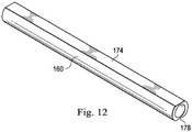
- the conductor 170 extends a long a flat 174 of the tubular member 160 and is electrically coupled to an embedded conductor of the central portion 102 at connection 176.
- the conductors 170 can be electrically coupled to the embedded conductor using any suitable techniques, including without limitation solder, physical contact, an electric coupler, etc.
- the conductor 172 extends a long a flat 178 of the tubular member 160 and is electrically coupled to an embedded conductor of the central portion 102 at connection 180.
- the conductors 172 can be electrically coupled to the embedded conductor using any suitable techniques, including without limitation solder, physical contact, an electric coupler, etc.
- the embedded conductors are exposed for electrical coupling to conductors 170 and 172 by removing a portion of the outer layer 132 covering the embedded conductors for a certain length along the longitudinal axis of the central portion 102. In some implementations, the embedded conductors are exposed for electrical coupling to conductors 170 and 172 at an end surface extending perpendicular to the longitudinal axis of the central portion 102. That is, the embedded conductors are not exposed along the length of the central portion, but rather are exposed at an end surface of the outer layer 132.
- Fig. 12 provides a perspective view of the tubular member 160 that shows the flats 174 and 178.
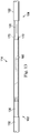
- Fig. 13 provides a side view of the transition section 114 showing the engagement of the core members 120 and 130 within the tubular member 160 and the conductors 170 and 172 extending over the tubular member 160.
- an outer layer 182 is formed over the conductors 170, 172, the tubular member 160, and the core members 120 and 130.
- the outer layer 182 extends along the length of the intravascular device 100 between the central portion 102 and the distal portion 104 a distance 184.
- the distance 184 results in the outer layer 182 covering the transition section 114 and portions of each of the flexible element 122 of the distal portion 104 and the outer layer 132 of the central portion 102.
- the outer layer 182 may cover a lesser amount of the transition section 114 and/or greater or lesser amounts of the central portion 102 and/or the distal portion 104 in other instances.
- the outer layer 182 can be formed of any suitable material.
- the outer layer 182 is a polymer material configured to seal the transition section 114.
- the outer layer 182 is a PET shrink fit tubing in some instances.
- An adhesive is placed inside the PET shrink fit tubing to ensure adequate moisture barrier for the electrical connections in some implementations.
- a coating is provided on at least a portion of the intravascular device 100, which may include the transition section 114.
- the coating can be a suitable hydrophilic or hydrophobic coating.
- the coating provides increased lubricity.
- Exemplary coating materials include, without limitation, PTFE impregnated polyimide, silicone-based coatings, and hydrophilic based coatings.
- the coating will be a very thin layer of material.
- the coating has a thickness less than about 12.7 microns (0.0005"), less than about 2.54 microns (0.0001"), and/or less than about 1.27 microns (0.0005").
- the transition section 114 include a tubular member 190 and/or a tubular member 192.
- the tubular members 190 and 192 can be utilized to increase the diameter of the transition section 114 in the areas surrounding the core members 120 and/or 130.
- a portion of the core member 120 having a reduced outer diameter relative to the flexible element 122 and the tubular member 160 will be exposed between the flexible element 122 and the tubular member 160.
- tubular members 190 and 192 may be utilized to increase the diameters in these areas to reduce the overall variability in the outer diameter of the transition section 114.
- the tubular members are polymer tubings.
- the tubing is slit to allow for positioning over the core member 130 after positioning the tubular member 160.
- the tubular members 190 and 192 are PET shrink fit tubings. In some instances, only one of the tubular members 190 and 192 is utilized.
- the guide wires of the present disclosure can be connected to an instrument, such as a computing device (e.g. a laptop, desktop, or tablet computer) or a physiology monitor, that converts the signals received by the sensors into pressure and velocity readings.
- the instrument can further calculate Coronary Flow Reserve (CFR) and Fractional Flow Reserve (FFR) and provide the readings and calculations to a user via a user interface.
- CFR Coronary Flow Reserve
- FFR Fractional Flow Reserve
- a user interacts with a visual interface to view images associated with the data obtained by the intravascular devices of the present disclosure.
- Input from a user e.g., parameters or a selection
- the selection can be rendered into a visible display.
Description
- The present disclosure relates to intravascular devices, systems, and methods. In some embodiments, the intravascular devices are guide wires that include separate sections with engaged core components.
- Heart disease is very serious and often requires emergency operations to save lives. A main cause of heart disease is the accumulation of plaque inside the blood vessels, which eventually occludes the blood vessels. Common treatment options available to open up the occluded vessel include balloon angioplasty, rotational atherectomy, and intravascular stents. Traditionally, surgeons have relied on X-ray fluoroscopic images that are planar images showing the external shape of the silhouette of the lumen of blood vessels to guide treatment. Unfortunately, with X-ray fluoroscopic images, there is a great deal of uncertainty about the exact extent and orientation of the stenosis responsible for the occlusion, making it difficult to find the exact location of the stenosis. In addition, though it is known that restenosis can occur at the same place, it is difficult to check the condition inside the vessels after surgery with X-ray.
- A currently accepted technique for assessing the severity of a stenosis in a blood vessel, including ischemia causing lesions, is fractional flow reserve (FFR). FFR is a calculation of the ratio of a distal pressure measurement (taken on the distal side of the stenosis) relative to a proximal pressure measurement (taken on the proximal side of the stenosis). FFR provides an index of stenosis severity that allows determination as to whether the blockage limits blood flow within the vessel to an extent that treatment is required. The normal value of FFR in a healthy vessel is 1.00, while values less than about 0.80 are generally deemed significant and require treatment.
- Often intravascular catheters and guide wires are utilized to measure the pressure within the blood vessel, visualize the inner lumen of the blood vessel, and/or otherwise obtain data related to the blood vessel. To date, guide wires containing pressure sensors, imaging elements, and/or other electronic, optical, or electro-optical components have suffered from reduced performance characteristics compared to standard guide wires that do not contain such components. For example, the handling performance of previous guide wires containing electronic components have been hampered, in some instances, by the limited space available for the core wire after accounting for the space needed for the conductors or communication lines of the electronic component(s), the stiffness of the rigid housing containing the electronic component(s), and/or other limitations associated with providing the functionality of the electronic components in the limited space available within a guide wire. Further, due to its small diameter, in many instances the proximal connector portion of the guide wire (i.e., the connector(s) that facilitate communication between the electronic component(s) of the guide wire and an associated controller or processor) is fragile and prone to kinking, which can destroy the functionality of the guide wire. For this reason, surgeons are reluctant to remove the proximal connector from the guide wire during a procedure for fear of breaking the guide wire when reattaching the proximal connector. Having the guide wire coupled to the proximal connector further limits the maneuverability and handling of the guide wire.
- Further, a problem with existing pressure and flow guide wires is that they require a complex assembly of many discrete components. That complex assembly process has limitations on design performance of the guide wire. The use of separate conductive wires running down the length of the wire reduces the space available for more supportive cores and can result in numerous issues during use due to poor solder joints with conductive bands, electrical shorts due to insulation issues, and breakage of the delicate conductive wires.
- Accordingly, there remains a need for improved intravascular devices, systems, and methods that include one or more electronic, optical, or electro-optical components.
-
US 5 240 437 A refers to a guide wire assembly comprising a guide wire with first and second conductors which extend along the length thereof. The guide wire also comprises a flexible cable having first and second conductors which extend along the length thereof. The connector assembly includes a male connector with a sleeve and a conductive core which is mounted in the sleeve.US 6,290,656 B1 A refers to a guide wire having a damped force vibration mechanism which isolates vibrations or shockwaves which otherwise would be transmitted along the length of the guide wire to its distal end. The damped force vibration mechanism helps absorb some of the energy created during the exchange of a delivery catheter or an interventional device on the guide wire or any shock or force generated from an external source.WO 2007/145751 A2 refers to a composite guidewire comprising a proximal wire segment having a proximal end, a distal end and a longitudinal axis extending between the proximal end and the distal end, the distal end of the proximal wire segment being formed with a first flat planar bonding face which extends parallel to the longitudinal axis, the proximal wire segment having a first elasticity and means for joining together two different wire segments at a joint that provides improved (i) tensile strength, (ii) torque strength, (iii) bending moment performance, and (iv) failure mode characteristics, among other things, and which is suitable for medical applications. - The present disclosure is directed to intravascular devices, systems, and methods that include a guide wire having a separate sections coupled together by engaging core components.
- The present disclosure provides a more robust sensing guide wire that avoids the assembly and performance issues of prior sensing guide wires. Guide wires of the present disclosure have one or more transition sections that facilitate coupling of different portions of the guide wire. Any type of sensor can be connected to guide wires of the present disclosure. In certain embodiments, only a single sensor is connected to the guide wire. In other embodiments, multiple sensors are connected to the guide wire. All of the sensors may be the same. Alternatively, the sensors may differ from each other and measure different characteristics inside a vessel. Exemplary sensors are pressure, flow, and temperature sensors. Generally, any type of pressure sensor may be used with the guide wires of the present disclosure, including piezoresistive, optical and/or combinations thereof. In certain embodiments, the pressure sensor includes a crystalline semi-conductor material. Similarly, any type of flow sensor may be used with guide wires of the present disclosure. In certain embodiments, the flow sensor includes an ultrasound transducer, such as a Doppler ultrasound transducer. The guide wire can include both a pressure sensor and a flow sensor.
- Another aspect of the present disclosure provides methods for manufacturing and/or assembling an intravascular device. The methods can include providing a proximal portion having a proximal core member and at least one proximal electrical conductor, wherein a distal section of the proximal core member includes a first engagement structure; providing a distal portion having a distal core member, a sensing element, and at least one distal electrical conductor coupled to the sensing element, wherein a proximal section of the distal core member includes a second engagement structure; and coupling the proximal portion to the distal portion, including: securing the proximal core member to the distal core member, wherein securing the proximal core member to the distal core member includes engaging the first engagement structure with the second engagement structure; and electrically coupling the at least one proximal electrical conductor to the at least one distal electrical conductor such that the at least one proximal electrical conductor is in electrical communication with the sensing element.
- In another aspect, sensing guide wires are provided. The guide wires can include a proximal portion having a proximal core member and at least one proximal electrical conductor and a distal portion coupled to the proximal portion, the distal portion having a distal core member, a sensing element, and at least one distal electrical conductor coupled to the sensing element, wherein engagement structures of the proximal and distal core members are engaged and wherein the at least one distal electrical conductor is coupled to the at least one proximal electrical conductor such that the at least one proximal electrical conductor is in electrical communication with the sensing element.
- Another aspect of the present disclosure provides methods for measuring a characteristic inside a vessel. The methods can include providing a sensing guide wire in accordance with the present disclosure, inserting the guide wire into a vessel, and utilizing one or more sensing elements of the guide wire to measure one or more characteristics inside the vessel.
- Additional aspects, features, and advantages of the present disclosure will become apparent from the following detailed description.
- Illustrative embodiments of the present disclosure will be described with reference to the accompanying drawings, of which:
-
FIG. 1 is a diagrammatic, schematic side view of an intravascular device according to an embodiment of the present disclosure. -
FIG. 2 is a perspective view of a transition section of an intravascular device according to an embodiment of the present disclosure. -
FIG. 3 is a side view of components of a transition section of an intravascular device according to an embodiment of the present disclosure. -
FIG. 4 is a perspective view of an engagement structure of a core component according to an embodiment of the present disclosure. -
FIG. 5 is a side view of the engagement structure of the core component ofFig. 4 . -
FIG. 6 is a bottom view of the engagement structure of the core component ofFigs. 4 and 5 . -
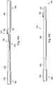
FIG. 7 is a side view of components of a transition section of an intravascular device according to an embodiment of the present disclosure. -
FIG. 8A is a side view of the components of the transition section of an intravascular device ofFig. 7 shown in arrangement according to an embodiment of the present disclosure. -
FIG. 8B is a side view of the components of the transition section of an intravascular device ofFig. 7 shown in another arrangement according to an embodiment of the present disclosure. -
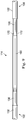
FIG. 9 is a side view of components of a transition section of an intravascular device according to an embodiment of the present disclosure. -
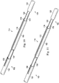
FIG. 10 is a perspective view of components of a transition section of an intravascular device according to an embodiment of the present disclosure. -
FIG. 11 is a perspective view of components of a transition section of an intravascular device according to an embodiment of the present disclosure. -
FIG. 12 is a perspective view of a component of a transition section of an intravascular device according to an embodiment of the present disclosure. -
FIG. 13 is a side view of components of a transition section of an intravascular device according to an embodiment of the present disclosure. -
FIG. 14 is a side view of components of a transition section of an intravascular device according to an embodiment of the present disclosure. -
FIG. 15 is a side view of components of a transition section of an intravascular device according to an embodiment of the present disclosure. - For the purposes of promoting an understanding of the principles of the present disclosure, reference will now be made to the embodiments illustrated in the drawings, and specific language will be used to describe the same. It is nevertheless understood that no limitation to the scope of the disclosure is intended. Any alterations and further modifications to the described devices, systems, and methods, and any further application of the principles of the present disclosure are fully contemplated and included within the present disclosure as would normally occur to one skilled in the art to which the disclosure relates. In particular, it is fully contemplated that the features, components, and/or steps described with respect to one embodiment may be combined with the features, components, and/or steps described with respect to other embodiments of the present disclosure. For the sake of brevity, however, the numerous iterations of these combinations will not be described separately.
- As used herein, "flexible elongate member" or "elongate flexible member" includes at least any thin, long, flexible structure that can be inserted into the vasculature of a patient. While the illustrated embodiments of the "flexible elongate members" of the present disclosure have a cylindrical profile with a circular cross-sectional profile that defines an outer diameter of the flexible elongate member, in other instances all or a portion of the flexible elongate members may have other geometric cross-sectional profiles (e.g., oval, rectangular, square, elliptical, etc.) or non-geometric cross-sectional profiles. Flexible elongate members include, for example, guide wires and catheters. In that regard, catheters may or may not include a lumen extending along its length for receiving and/or guiding other instruments. If the catheter includes a lumen, the lumen may be centered or offset with respect to the cross-sectional profile of the device.
- In most embodiments, the flexible elongate members of the present disclosure include one or more electronic, optical, or electro-optical components. For example, without limitation, a flexible elongate member may include one or more of the following types of components: a pressure sensor, a flow sensor, a temperature sensor, an imaging element, an optical fiber, an ultrasound transducer, a reflector, a mirror, a prism, an ablation element, an RF electrode, a conductor, and/or combinations thereof. Generally, these components are configured to obtain data related to a vessel or other portion of the anatomy in which the flexible elongate member is disposed. Often the components are also configured to communicate the data to an external device for processing and/or display. In some aspects, embodiments of the present disclosure include imaging devices for imaging within the lumen of a vessel, including both medical and non-medical applications. However, some embodiments of the present disclosure are particularly suited for use in the context of human vasculature. Imaging of the intravascular space, particularly the interior walls of human vasculature can be accomplished by a number of different techniques, including ultrasound (often referred to as intravascular ultrasound ("IVUS") and intracardiac echocardiography ("ICE")) and optical coherence tomography ("OCT"). In other instances, infrared, thermal, or other imaging modalities are utilized.
- The electronic, optical, and/or electro-optical components of the present disclosure are often disposed within a distal portion of the flexible elongate member. As used herein, "distal portion" of the flexible elongate member includes any portion of the flexible elongate member from the mid-point to the distal tip. As flexible elongate members can be solid, some embodiments of the present disclosure will include a housing portion at the distal portion for receiving the electronic components. Such housing portions can be tubular structures attached to the distal portion of the elongate member. Some flexible elongate members are tubular and have one or more lumens in which the electronic components can be positioned within the distal portion.
- The electronic, optical, and/or electro-optical components and the associated communication lines are sized and shaped to allow for the diameter of the flexible elongate member to be very small. For example, the outside diameter of the elongate member, such as a guide wire or catheter, containing one or more electronic, optical, and/or electro-optical components as described herein are between about 0.0007" (0.0178 mm) and about 0.118" (3.0 mm), with some particular embodiments having outer diameters of approximately 0.014" (0.3556 mm), approximately 0.018" (0.4572 mm), and approximately .035" (.889mm). As such, the flexible elongate members incorporating the electronic, optical, and/or electro-optical component(s) of the present application are suitable for use in a wide variety of lumens within a human patient besides those that are part or immediately surround the heart, including veins and arteries of the extremities, renal arteries, blood vessels in and around the brain, and other lumens.
- "Connected" and variations thereof as used herein includes direct connections, such as being glued or otherwise fastened directly to, on, within, etc. another element, as well as indirect connections where one or more elements are disposed between the connected elements.
- "Secured" and variations thereof as used herein includes methods by which an element is directly secured to another element, such as being glued or otherwise fastened directly to, on, within, etc. another element, as well as indirect techniques of securing two elements together where one or more elements are disposed between the secured elements.
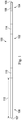
- Referring now to
Fig. 1 , shown therein is a portion of anintravascular device 100 according to an embodiment of the present disclosure. In that regard, theintravascular device 100 includes a flexible elongate member having acentral portion 102, adistal portion 104 adjacent adistal end 105, and aproximal portion 106 adjacent aproximal end 107. Acomponent 108 is positioned within thedistal portion 104 proximal of thedistal tip 105. Generally, thecomponent 108 is representative of one or more electronic, optical, or electro-optical components. In that regard, thecomponent 108 is a pressure sensor, a flow sensor, a temperature sensor, an imaging element, an optical fiber, an ultrasound transducer, a reflector, a mirror, a prism, an ablation element, an RF electrode, a conductor, and/or combinations thereof. The specific type of component or combination of components can be selected based on an intended use of the intravascular device. In some instances, thecomponent 108 is positioned less than 10 cm, less than 5, or less than 3 cm from thedistal tip 105. In some instances, thecomponent 108 is positioned within a housing of the flexibleelongate member 102. In that regard, the housing is a separate component secured to other components of thedistal portion 104 in some instances. In other instances, the housing is integrally formed as a part of a component of thedistal portion 104. - The
intravascular device 100 also includes aconnector 110 adjacent theproximal portion 106 of the device. In that regard, theconnector 110 is spaced from theproximal end 107 of theintravascular device 100 by adistance 112. Generally, thedistance 112 is between 0% and 50% of the total length of theintravascular device 100. While the total length of the intravascular device can be any length, in some embodiments the total length is between about 1300 mm and about 4000 mm, with some specific embodiments have a length of 1400 mm, 1900 mm, and 3000 mm. Accordingly, in some instances theconnector 110 is positioned at theproximal end 107. In other instances, theconnector 110 is spaced from theproximal end 107. For example, in some instances theconnector 110 is spaced from theproximal end 107 between about 0 mm and about 1400 mm. In some specific embodiments, theconnector 110 is spaced from the proximal end by a distance of 0 mm, 300 mm, and 1400 mm. - The
connector 110 is configured to facilitate communication between theintravascular device 100 and another device. More specifically, in some embodiments theconnector 110 is configured to facilitate communication of data obtained by thecomponent 108 to another device, such as a computing device or processor. Accordingly, in some embodiments theconnector 110 is an electrical connector. In such instances, theconnector 110 provides an electrical connection to one or more electrical conductors that extend along the length of the flexibleelongate member 102 and are electrically coupled to thecomponent 108. In other embodiments, theconnector 110 is an optical connector. In such instances, theconnector 110 provides an optical connection to one or more optical communication pathways (e.g., fiber optic cable) that extend along the length of the flexibleelongate member 102 and are optically coupled to thecomponent 108. Further, in some embodiments theconnector 110 provides both electrical and optical connections to both electrical conductor(s) and optical communication pathway(s) coupled to thecomponent 108. In that regard, it should be noted thatcomponent 108 is comprised of a plurality of elements in some instances. Theconnector 110 is configured to provide a physical connection to another device, either directly or indirectly. In some instances, theconnector 110 is configured to facilitate wireless communication between theintravascular device 100 and another device. Generally, any current or future developed wireless protocol(s) may be utilized. In yet other instances, theconnector 110 facilitates both physical and wireless connection to another device. - As noted above, in some instances the
connector 110 provides a connection between thecomponent 108 of theintravascular device 100 and an external device. Accordingly, in some embodiments one or more electrical conductors, one or more optical pathways, and/or combinations thereof extend along the length of theintravascular device 100 between theconnector 110 and thecomponent 108 to facilitate communication between theconnector 110 and thecomponent 108. Generally, any number of electrical conductors, optical pathways, and/or combinations thereof can extend along the length of theintravascular device 100 between theconnector 110 and thecomponent 108. In some instances, between one and ten electrical conductors and/or optical pathways extend along the length of theintravascular device 100 between theconnector 110 and thecomponent 108. The number of communication pathways and the number of electrical conductors and optical pathways is determined by the desired functionality of thecomponent 108 and the corresponding elements that definecomponent 108 to provide such functionality. - As shown in
Figs. 1 and2 , theintravascular device 100 includes atransition section 114 where thecentral portion 102 is coupled to thedistal portion 104.Figs. 3-15 described below discuss various features of thetransition section 114 in accordance with the present disclosure. In that regard, it is understood that the features described below for coupling thecentral portion 102 and thedistal portion 104 may be similarly applied to couple any two parts of theintravascular device 100 together, including (1) coupling any two of thecentral portion 102, thedistal portion 104, and/or theproximal portion 106 together, (2) coupling two or more sections together that collectively define thecentral portion 102, thedistal portion 104, and/or theproximal portion 106; and/or (3) combinations of (1) and (2). While the following description will focus on features of thetransition section 114 in the context of a specific example of thecentral portion 102 and a specific example of thedistal portion 104, no limitation is intended thereby. Instead, it is understood that the concepts of the present disclosure are applicable to intravascular devices having various types of proximal, distal, and central portions. In some particular instances, the transition section is utilized to couple two or more parts, components, sections, and/or portions similar to those described in one or more ofUS 5 125 137 ,US 5 873 835 ,US 6 106 476 ,US 6 551 250 , andUS 13/931,052 US 14/135,117 US 14/137,364 US 14/139,543 US 14/143,304 US 61/935,113 - Referring now to
Figs. 3-15 , shown therein are aspects of the transition section(s) of the intravascular devices of the present disclosure. In that regard, one of the major issues associated with existing functional guide wires is poor mechanical performance as compared to frontline guide wires. The transition section(s) of the present disclosure facilitate (1) intravascular devices having improved mechanical performance; (2) selection of the best performance core material(s) for different portions of the intravascular device; (3) a simplified manufacturing process that allows for (a) one or more portions of the intravascular device to be completely assembled and tested as a functional unit prior to attachment to the other portion(s) of the intravascular device, (b) the use of shorter, individual portions that reduce the working space needed for assembly, and (c) reduction of the amount, and corresponding cost, of core wire and other components that are scrapped during typical assembly; (4) the creation of a family of intravascular devices where the particular portions/sections used to form the intravascular device may be selected and coupled together using one or more transition sections based on the desired functionality of the intravascular device; (5) minimizing the amount of handling of each portion/section throughout the build process because the different portion/section can be manufactured/assembled separately and then coupled together; and (6) simplifying the electrical/optical connection process utilized to connect communication pathways between portions/sections by utilizing a uniform approach. - Referring more specifically to
Fig. 3 , as shown, thedistal portion 104 includes acore member 120 and aflexible element 122 according to an embodiment of the present disclosure. As shown, thecore member 120 has an outer diameter 124 that is less than an outer diameter 126 of theflexible element 122. In some instances, the outer diameter 126 of theflexible element 122 is the same or substantially the same as the desired outer diameter of theintravascular device 100. Accordingly, in some particular embodiments the outer diameter 126 of theflexible element 122 is approximately 0.356 mm (0.014"), such as between 0.3505 mm (0.0138") and 0.3607 mm (0.0138"). Theflexible element 122 may be a coil, a polymer tubing, a coil-embedded polymer tubing, and/or combinations thereof. In that regard, theflexible element 122 may comprise multiple components in some implementations. Though not shown inFig. 3 , thedistal portion 104 may also include a further flexible element extending distally from the component 108 (or a housing containing component 108) to thedistal tip 105 of theintravascular device 100. Again, this distal flexible element may be a coil, a polymer tubing, and/or a coil-embedded polymer tubing. In some instances, the distal flexible element is radiopaque and/or includes a radiopaque tip. In some implementations, a flow sensor is positioned at thedistal tip 105 of theintravascular device 100. Generally, thedistal portion 104 of theintravascular device 100 may include features similar to those described in any of the patents and applications mentioned above, but utilizing the transition sections of the present disclosure described below. - The
core member 120 can be formed of any suitable material such as stainless steel, nickel and titanium alloys (such as Nitinol and NiTiCo), polyetheretherketone, 304V stainless steel, MP35N, or other metallic or polymeric materials. As discussed in greater detail below, a proximal section of thecore member 120 includes anengagement structure 128 that allows thecore member 120 to be coupled with acore member 130 of thecentral portion 102. - As also shown in
Fig. 3 , thecentral portion 102 includes acore member 130 and anouter layer 132 according to an embodiment of the present disclosure. As shown, thecore member 120 includessection 134 andsection 136 having different profiles. In particular, in the illustratedembodiment sections section 136 has anouter diameter 138 that is less than anouter diameter 140 ofsection 134. Similarly, theouter diameter 138 ofsection 136 is less than anouter diameter 142 of theouter layer 132. In some instances, theouter diameter 142 of theouter layer 132 is the same or substantially the same as the desired outer diameter of theintravascular device 100. Accordingly, in some particular embodiments theouter diameter 142 of theouter layer 132 is approximately 0.356 mm (0.014"), such as between 0.3505 mm (0.0138") and 0.3607 mm (0.0142"). - The
outer layer 132 includes conductors embedded therein. As discussed below, in the illustrated embodiments of the present disclosure, two conductors are embedded within theouter layer 132 of thecentral portion 102. In that regard, the conductors are fully encapsulated by the material forming theouter layer 132, which is a polymer in some instances. In some embodiments, an insulating layer-such as part of theouter layer 132 or a separate layer-is formed between the conductors and thecore member 130. To that end, the insulating layer can be utilized to electrically isolate the conductors from thecore member 130. As a result, each of the conductors embedded in theouter layer 132 and/or thecore member 130 can be utilized as an independent electrical communication pathway of theintravascular device 100. - Each of the embedded conductors is formed of a conductive material, such as copper, gold, silver, platinum, or other suitable conductive material. Generally, the size of the conductors is selected to allow the conductors to be fully embedded within the material forming the
outer layer 132. Accordingly, in some instances the conductor is between a 24 AWG conductor and a 64 AWG conductor, with some embodiments utilizing 48 AWG conductors. In other instances, larger or smaller conductors are utilized. In certain embodiments, the conductors are space substantially equally around a circumference of thecentral portion 102. However, the conductors may be embedded in any suitable manner and/or pattern, including symmetric, non-symmetric, geometric, and non-geometric patterns. In some instances, the conductors are conductive ribbons that allow for ease of connection and optimization of the coating wall thickness to maximize the core diameter. - The
core member 130 can be formed of any suitable material such as stainless steel, nickel and titanium alloys (such as Nitinol and NiTiCo), polyetheretherketone, 304V stainless steel, MP35N, or other metallic or polymeric materials. A distal section of thecore member 130 includes anengagement structure 144 that allows thecore member 130 to be coupled with thecore member 120 of thedistal portion 104. Generally, theengagement structures core members engagement structures core members engagement structures core member engagement structures - Referring now to
Figs. 4-6 , shown therein are aspects of theengagement structure 128 according to the present disclosure. In the illustrated embodiments of the present disclosure, theengagement structures engagement structure 144 will not be described separately. However, in other embodiments theengagement structures engagement structure 128 includes a flat 150 and a flat 152 that are staggered from one another. In that regard, flat 150 is recessed a greater extent than flat 152. - For example, in the illustrated embodiment flat 150 is positioned approximately 33% of the way through the
core member 120, whereas flat 152 is positioned approximately 67% of the way through thecore member 120. Theengagement structure 128 also includes atransition 154 between the flat 150 and the outer surface of thecore member 120. Similarly, theengagement structure 128 includes atransition 156 between the flat 150 and the flat 152. In the illustrated embodiment, thetransitions engagement structure 128 is defined in thecore member 120 by removing portions of the core member utilizing a suitable manufacturing technique, such as grinding, etching, laser ablation, and/or combinations thereof. In other instances, theengagement structure 128 is defined in thecore member 120 as part of a molding process. - Referring again to
Fig. 3 , to couple thecentral portion 102 to thedistal portion 104 theengagement structures flats engagement structure 128 are engaged with corresponding flats of theengagement structure 144, as shown. Further, in order to provide the desired alignment in the axial direction thecentral portion 102 and thedistal portion 104 can be pulled away from each other such that thetransition 156 of theengagement structure 128 engages a corresponding transition of theengagement structure 144. With thecore members engagement structures tubular member 160 can be positioned around theengagement structures core members tubular member 160 can be formed of any suitable material, including metals and polymers, including without limitation 304V Stainless Steel, Nitinol, NiTiCo, and Polyimide. In some instances, thetubular member 160 is a hypotube. Solder or adhesive can be flown into the interior of thetubular member 160 to fixedly secure thecore members tubular member 160. In that regard, the solder or adhesive will fill the gaps between thecore members core members tubular member 160 to provide a solid physical connection between the components. - As shown in
Figs. 8A and 8B , thetubular member 160 can be initially placed around thecore member 120 at a position distal of theengagement structure 128 to allow theengagement structures engagement structures tubular member 160 can be translated proximally alongcore member 120, as shown byarrow 162, to a position surrounding the engagedengagement structures tubular member 160 positioned around theengagement structures core members core members 120 and 130 (e.g., by pulling them apart) when coupling them together. Note that a similar approach can be utilized where the tubular member begins aroundcore member 130 proximal ofengagement structure 144 and is then translated distally to surround the engagedengagement structures core member tubular member 160 positioned around the engagement structures. Further, in some embodiments theintravascular device 100 does not includetubular member 160, but may include other element(s) or structure(s) to solidify the joint. - Referring now to
Fig. 9-13 ,electrical conductors distal portion 104 have been electrically coupled to the embedded conductors in theouter layer 132 of thecentral portion 102. In some embodiments, an insulating layer is formed around thecore members tubular member 160 prior to extending theelectrical conductors core members tubular member 160 for connection to the embedded conductors. In that regard, the insulating layer serves to electrically isolate thecore members tubular member 160 from theconductors conductors core member tubular member 160. - As shown in
Figs. 10 and 11 , thetubular member 160 includes flattened portions to allow theconductors tubular member 160 without increasing the outer diameter of thetransition section 114 beyond the desired outer diameter of theintravascular device 100. For similar reasons, in some instances theconductors Fig. 10 , theconductor 170 extends a long a flat 174 of thetubular member 160 and is electrically coupled to an embedded conductor of thecentral portion 102 atconnection 176. Theconductors 170 can be electrically coupled to the embedded conductor using any suitable techniques, including without limitation solder, physical contact, an electric coupler, etc. Similarly, as shown inFig. 11 , theconductor 172 extends a long a flat 178 of thetubular member 160 and is electrically coupled to an embedded conductor of thecentral portion 102 atconnection 180. Theconductors 172 can be electrically coupled to the embedded conductor using any suitable techniques, including without limitation solder, physical contact, an electric coupler, etc. - In some implementations, the embedded conductors are exposed for electrical coupling to
conductors outer layer 132 covering the embedded conductors for a certain length along the longitudinal axis of thecentral portion 102. In some implementations, the embedded conductors are exposed for electrical coupling toconductors central portion 102. That is, the embedded conductors are not exposed along the length of the central portion, but rather are exposed at an end surface of theouter layer 132.Fig. 12 provides a perspective view of thetubular member 160 that shows theflats Fig. 13 provides a side view of thetransition section 114 showing the engagement of thecore members tubular member 160 and theconductors tubular member 160. - Referring now to
Fig. 14 , anouter layer 182 is formed over theconductors tubular member 160, and thecore members outer layer 182 extends along the length of theintravascular device 100 between thecentral portion 102 and the distal portion 104 adistance 184. As shown, thedistance 184 results in theouter layer 182 covering thetransition section 114 and portions of each of theflexible element 122 of thedistal portion 104 and theouter layer 132 of thecentral portion 102. Theouter layer 182 may cover a lesser amount of thetransition section 114 and/or greater or lesser amounts of thecentral portion 102 and/or thedistal portion 104 in other instances. Theouter layer 182 can be formed of any suitable material. In some instances, theouter layer 182 is a polymer material configured to seal thetransition section 114. Theouter layer 182 is a PET shrink fit tubing in some instances. An adhesive is placed inside the PET shrink fit tubing to ensure adequate moisture barrier for the electrical connections in some implementations. In some instances, a coating is provided on at least a portion of theintravascular device 100, which may include thetransition section 114. In that regard, the coating can be a suitable hydrophilic or hydrophobic coating. In some implementations, the coating provides increased lubricity. Exemplary coating materials include, without limitation, PTFE impregnated polyimide, silicone-based coatings, and hydrophilic based coatings. Generally, the coating will be a very thin layer of material. For example, in some implementations the coating has a thickness less than about 12.7 microns (0.0005"), less than about 2.54 microns (0.0001"), and/or less than about 1.27 microns (0.0005"). - Referring now to
Fig. 15 , in some instances thetransition section 114 include atubular member 190 and/or atubular member 192. In that regard, thetubular members transition section 114 in the areas surrounding thecore members 120 and/or 130. In that regard, in order to allow thetubular member 160 to translate along the length of thecore member 120 to facilitate engagement of thecore members tubular member 160 being positioned around the engagedengagement structures core member 120 having a reduced outer diameter relative to theflexible element 122 and thetubular member 160 will be exposed between theflexible element 122 and thetubular member 160. Similarly, a portion of thecore member 130 having a reduced outer diameter relative to thetubular member 160 and theouter layer 132 may be exposed between thetubular member 160 and theouter layer 132. Accordingly,tubular members transition section 114. In some instances, the tubular members are polymer tubings. In some implementations, the tubing is slit to allow for positioning over thecore member 130 after positioning thetubular member 160. In some particular embodiments, thetubular members tubular members - The guide wires of the present disclosure can be connected to an instrument, such as a computing device (e.g. a laptop, desktop, or tablet computer) or a physiology monitor, that converts the signals received by the sensors into pressure and velocity readings. The instrument can further calculate Coronary Flow Reserve (CFR) and Fractional Flow Reserve (FFR) and provide the readings and calculations to a user via a user interface. In some embodiments, a user interacts with a visual interface to view images associated with the data obtained by the intravascular devices of the present disclosure. Input from a user (e.g., parameters or a selection) are received by a processor in an electronic device. The selection can be rendered into a visible display.
- Persons skilled in the art will also recognize that the apparatus, systems, and methods described above can be modified in various ways. Accordingly, persons of ordinary skill in the art will appreciate that the embodiments encompassed by the present disclosure are not limited to the particular exemplary embodiments described above. In that regard, although illustrative embodiments have been shown and described, a wide range of modification, change, and substitution is contemplated in the foregoing disclosure. It is understood that such variations may be made to the foregoing without departing from the scope of the present disclosure. Accordingly, it is appropriate that the appended claims be construed broadly and in a manner consistent with the present disclosure.
Claims (13)
- A sensing guide wire, comprising:a proximal portion (106) having a proximal core member (130) and at least one proximal electrical conductor, wherein a distal section of the proximal core member includes a first engagement structure (144);a distal portion (104) coupled to the proximal portion, the distal portion having a distal core member (120), a sensing element, and at least one distal electrical conductor (170, 172) coupled to the sensing element, wherein a proximal section of the distal core member includes a second engagement structure (128) engaged with the first engagement structure of the proximal core member and wherein the at least one distal electrical conductor is coupled to the at least one proximal electrical conductor such that the at least one proximal electrical conductor is in electrical communication with the sensing element (108);a tubular member (160) positioned around the first and second engagement structures, and the tubular member includes at least one flat (174, 178), wherein the at least one distal electrical conductor extends along the at least one flat on the outside of the tubular member.
- The guide wire of claim 1, wherein the sensing element is a pressure sensor and/or a flow sensor.
- The guide wire of claim 1, wherein the tubular member is a hypotube.
- The guide wire of claim 1, wherein the hypotube (160) includes two flats (174, 178), wherein the at least one distal electrical conductor includes two conductors, and wherein the two distal electrical conductors (170, 172) extend along the two flats of the hypotube.
- The guide wire of claim 4, wherein the distal core member is electrically coupled to the sensing element and the proximal core member such that the proximal core member is in electrical communication with the sensing element.
- The guide wire of claim 1, wherein each of the proximal core member and the distal core member is formed of at least one of 304V Stainless Steel, Nitinol, NiTiCo, and MP35N.
- The guide wire of claim 6, wherein the distal core member is formed of a different material than the proximal core member.
- The guide wire of claim 1, wherein the first engagement structure (128) includes a flat (150, 152) that is engaged with a flat of the second engagement structure (144).
- The guide wire of claim 1, wherein the first engagement structure includes a projection that is engaged with a recess of the second engagement structure.
- The guide wire of claim 1, wherein the distal portion includes a first flexible element (122) proximal of the sensing element (108) and a second flexible element distal of the sensing element.
- The guide wire of claim 10, wherein the first flexible element (122) and/or the second flexible element includes at least one of a coil and a polymer tubing.
- The guide wire of claim 1, further comprising an insulating coating extending over at least a transition region where the proximal portion is coupled to the distal portion.
- A method of forming a sensing guide wire, the method comprising:providing a proximal portion having a proximal core member and at least one proximal electrical conductor, wherein a distal section of the proximal core member includes a first engagement structure;providing a distal portion having a distal core member, a sensing element, and at least one distal electrical conductor coupled to the sensing element, wherein a proximal section of the distal core member includes a second engagement structure; andcoupling the proximal portion to the distal portion, including:securing the proximal core member to the distal core member, wherein securing the proximal core member to the distal core member includes engaging the first engagement structure with the second engagement structure; andelectrically coupling the at least one proximal electrical conductor to the at least one distal electrical conductor such that the at least one proximal electrical conductor is in electrical communication with the sensing element;wherein coupling the proximal portion to the distal portion includes
positioning a tubular member, including at least one flat (174, 178), around the engaged first and second engagement structures, and
extending the at least one distal electrical conductor along the at least one flat on the outside of the tubular member.
Applications Claiming Priority (2)
| Application Number | Priority Date | Filing Date | Title |
|---|---|---|---|
| US201461982080P | 2014-04-21 | 2014-04-21 | |
| PCT/US2015/026643 WO2015164250A1 (en) | 2014-04-21 | 2015-04-20 | Intravascular devices, systems, and methods having separate sections with engaged core components |
Publications (3)
| Publication Number | Publication Date |
|---|---|
| EP3133987A1 EP3133987A1 (en) | 2017-03-01 |
| EP3133987A4 EP3133987A4 (en) | 2017-04-26 |
| EP3133987B1 true EP3133987B1 (en) | 2019-09-11 |
Family
ID=54320931
Family Applications (1)
| Application Number | Title | Priority Date | Filing Date |
|---|---|---|---|
| EP15783695.8A Active EP3133987B1 (en) | 2014-04-21 | 2015-04-20 | Sensing guide wire and method of manufacturing thereof |
Country Status (5)
| Country | Link |
|---|---|
| US (2) | US10772564B2 (en) |
| EP (1) | EP3133987B1 (en) |
| JP (3) | JP6586425B2 (en) |
| CN (1) | CN106231999B (en) |
| WO (1) | WO2015164250A1 (en) |
Families Citing this family (9)
| Publication number | Priority date | Publication date | Assignee | Title |
|---|---|---|---|---|
| US9624095B2 (en) | 2012-12-28 | 2017-04-18 | Volcano Corporation | Capacitive intravascular pressure-sensing devices and associated systems and methods |
| WO2015164250A1 (en) * | 2014-04-21 | 2015-10-29 | Koninklijke Philips N.V. | Intravascular devices, systems, and methods having separate sections with engaged core components |
| CN106691506A (en) * | 2016-12-29 | 2017-05-24 | 天津恒宇医疗科技有限公司 | OCT imaging conduit with high imaging quality |
| JP7372907B2 (en) * | 2017-08-31 | 2023-11-01 | コーニンクレッカ フィリップス エヌ ヴェ | Sensing guidewire with integrated proximal locking feature |
| WO2020016986A1 (en) | 2018-07-19 | 2020-01-23 | 朝日インテック株式会社 | Guide wire and guide wire manufacturing method |
| US11406416B2 (en) * | 2018-10-02 | 2022-08-09 | Neuravi Limited | Joint assembly for vasculature obstruction capture device |
| US20210178127A1 (en) * | 2019-12-16 | 2021-06-17 | Stryker Corporation | Guidewires for medical devices |
| US20230270388A1 (en) | 2020-06-09 | 2023-08-31 | Philips Image Guided Therapy Corporation | Physiology sensing intraluminal device with reibling method |
| JP2022190427A (en) * | 2021-06-14 | 2022-12-26 | 朝日インテック株式会社 | guide wire |
Family Cites Families (50)
| Publication number | Priority date | Publication date | Assignee | Title |
|---|---|---|---|---|
| US4691709A (en) | 1986-07-01 | 1987-09-08 | Cordis Corporation | Apparatus for measuring velocity of blood flow in a blood vessel |
| US4958642A (en) * | 1988-11-02 | 1990-09-25 | Cardiometrics, Inc. | Guide wire assembly with electrical functions and male and female connectors for use therewith |
| US5240437A (en) * | 1988-11-02 | 1993-08-31 | Cardiometrics, Inc. | Torqueable guide wire assembly with electrical functions, male and female connectors for use therewith and system and apparatus for utilizing the same |
| US5125137A (en) | 1990-09-06 | 1992-06-30 | Cardiometrics, Inc. | Method for providing a miniature ultrasound high efficiency transducer assembly |
| US5873835A (en) | 1993-04-29 | 1999-02-23 | Scimed Life Systems, Inc. | Intravascular pressure and flow sensor |
| CA2198909A1 (en) * | 1994-09-02 | 1996-03-14 | Robert Z. Obara | Ultra miniature pressure sensor and guidewire using the same and method |
| US6350266B1 (en) * | 1995-02-02 | 2002-02-26 | Scimed Life Systems, Inc. | Hybrid stone retrieval device |
| SE9600333D0 (en) * | 1995-06-22 | 1996-01-30 | Radi Medical Systems | Sensor arrangement |
| US6090052A (en) * | 1997-03-25 | 2000-07-18 | Radi Medical Systems Ab | Guide wire having a male connector |
| US5980471A (en) * | 1997-10-10 | 1999-11-09 | Advanced Cardiovascular System, Inc. | Guidewire with tubular connector |
| US6090050A (en) | 1998-07-16 | 2000-07-18 | Salix Medical, Inc. | Thermometric apparatus and method |
| WO2000053081A1 (en) | 1999-03-09 | 2000-09-14 | Florence Medical Ltd. | A method and system for pressure based measurements of cfr and additional clinical hemodynamic parameters |
| AU6722200A (en) | 1999-08-25 | 2001-03-19 | Florence Medical Ltd. | A method and system for stenosis identification, localization and characterization using pressure measurements |
| US6290656B1 (en) * | 1999-12-30 | 2001-09-18 | Advanced Cardiovascular Systems, Inc. | Guide wire with damped force vibration mechanism |
| US6354999B1 (en) | 2000-01-14 | 2002-03-12 | Florence Medical Ltd. | System and method for detecting, localizing, and characterizing occlusions and aneurysms in a vessel |
| US6551250B2 (en) | 2001-03-29 | 2003-04-22 | Hassan Khalil | Transit time thermodilution guidewire system for measuring coronary flow velocity |
| CA2462335C (en) * | 2001-10-05 | 2010-12-07 | Boston Scientific Limited | Composite guidewire |
| US6702762B2 (en) | 2001-12-27 | 2004-03-09 | Advanced Cardiovascular Systems, Inc. | Apparatus and method for joining two guide wire core materials without a hypotube |
| US7134994B2 (en) | 2002-05-20 | 2006-11-14 | Volcano Corporation | Multipurpose host system for invasive cardiovascular diagnostic measurement acquisition and display |
| CA2513275A1 (en) | 2003-01-16 | 2004-07-29 | Galil Medical Ltd. | Device, system, and method for detecting, localizing, and characterizing plaque-induced stenosis of a blood vessel |
| US20040176683A1 (en) | 2003-03-07 | 2004-09-09 | Katherine Whitin | Method and apparatus for tracking insertion depth |
| US6993974B2 (en) * | 2003-07-02 | 2006-02-07 | Radi Medical Systems Ab | Sensor and guide wire assembly |
| US7998090B2 (en) * | 2004-08-31 | 2011-08-16 | Abbott Cardiovascular Systems Inc. | Guide wire with core having welded wire segments |
| US20060052700A1 (en) | 2004-09-08 | 2006-03-09 | Radi Medical Systems Ab | Pressure measurement system |
| US8277386B2 (en) * | 2004-09-27 | 2012-10-02 | Volcano Corporation | Combination sensor guidewire and methods of use |
| US7799019B2 (en) * | 2005-05-10 | 2010-09-21 | Vivant Medical, Inc. | Reinforced high strength microwave antenna |
| WO2007047566A2 (en) | 2005-10-14 | 2007-04-26 | The Cleveland Clinic Foundation | System and method for characterizing vascular tissue |
| US20070255145A1 (en) * | 2006-04-28 | 2007-11-01 | Radi Medical Systems Ab | Sensor and guide wire assembly |
| WO2007145751A2 (en) * | 2006-05-12 | 2007-12-21 | Concert Medical Llc | Guidewire formed with composite construction and method for making the same |
| US20080077050A1 (en) * | 2006-09-08 | 2008-03-27 | Radi Medical Systems Ab | Electrical connector for medical device |
| US20080139951A1 (en) | 2006-12-08 | 2008-06-12 | Cardiac Pacemakers, Inc. | Detection of Stenosis |
| PL2334227T3 (en) | 2008-09-11 | 2022-09-12 | Acist Medical Systems, Inc. | Physiological sensor delivery device and fluid injection system |
| ES2635643T3 (en) | 2009-09-18 | 2017-10-04 | St. Jude Medical Coordination Center Bvba | Device to acquire physiological variables measured in a body |
| US8936631B2 (en) * | 2010-01-04 | 2015-01-20 | Covidien Lp | Apparatus and methods for treating hollow anatomical structures |
| JP2011166519A (en) | 2010-02-10 | 2011-08-25 | Seiko Epson Corp | Radio tag, management apparatus, and energy-saving system |
| JP5866371B2 (en) * | 2010-11-09 | 2016-02-17 | オプセンス インコーポレイテッド | Guide wire with internal pressure sensor |
| US20120172905A1 (en) * | 2010-12-30 | 2012-07-05 | Kimberly-Clark, Inc. | Tissue Removal Apparatus and Method of Manufacturing Same |
| GB201100136D0 (en) | 2011-01-06 | 2011-02-23 | Davies Helen C S | Apparatus and method of characterising a narrowing in a filled tube |
| GB201100137D0 (en) | 2011-01-06 | 2011-02-23 | Davies Helen C S | Apparatus and method of assessing a narrowing in a fluid tube |
| WO2012109039A1 (en) * | 2011-01-30 | 2012-08-16 | Warnking Reinhard J | System for detection of blood pressure using a pressure sensing guide wire |
| RU2014110702A (en) | 2011-08-20 | 2015-09-27 | Волкано Корпорэйшн | DEVICES, SYSTEMS AND METHODS OF VISUAL DISPLAY OF A VESSEL AND EVALUATION OF TREATMENT OPTIONS |
| US20130237864A1 (en) * | 2011-11-28 | 2013-09-12 | Scott T. Mazar | Steerable guide wire with pressure sensor and methods of use |
| US9364640B2 (en) * | 2012-05-07 | 2016-06-14 | St. Jude Medical Atrial Fibrillation Division, Inc. | Medical device guidewire with helical cutout and coating |
| US9351687B2 (en) | 2012-06-28 | 2016-05-31 | Volcano Corporation | Intravascular devices, systems, and methods |
| WO2014052818A1 (en) * | 2012-09-29 | 2014-04-03 | Mitralign, Inc. | Plication lock delivery system and method of use thereof |
| US20140180141A1 (en) | 2012-12-21 | 2014-06-26 | Volcano Corporation | Mounting Structures for Components of Intravascular Devices |
| US20140187980A1 (en) | 2012-12-28 | 2014-07-03 | Volcano Corporation | Hypotube Sensor Mount for Sensored Guidewire |
| WO2014105785A1 (en) | 2012-12-31 | 2014-07-03 | Volcano Corporation | In-wall hypotube sensor mount for sensored guidewire |
| US10791991B2 (en) | 2012-12-31 | 2020-10-06 | Philips Image Guided Therapy Corporation | Intravascular devices, systems, and methods |
| WO2015164250A1 (en) * | 2014-04-21 | 2015-10-29 | Koninklijke Philips N.V. | Intravascular devices, systems, and methods having separate sections with engaged core components |
-
2015
- 2015-04-20 WO PCT/US2015/026643 patent/WO2015164250A1/en active Application Filing
- 2015-04-20 CN CN201580020953.7A patent/CN106231999B/en active Active
- 2015-04-20 EP EP15783695.8A patent/EP3133987B1/en active Active
- 2015-04-20 JP JP2016563781A patent/JP6586425B2/en active Active
- 2015-04-21 US US14/692,443 patent/US10772564B2/en active Active
-
2019
- 2019-09-09 JP JP2019163477A patent/JP6826172B2/en active Active
-
2020
- 2020-09-14 US US17/019,506 patent/US11864918B2/en active Active
-
2021
- 2021-01-14 JP JP2021004174A patent/JP7216123B2/en active Active
Non-Patent Citations (1)
| Title |
|---|
| None * |
Also Published As
| Publication number | Publication date |
|---|---|
| US10772564B2 (en) | 2020-09-15 |
| EP3133987A4 (en) | 2017-04-26 |
| JP2017513604A (en) | 2017-06-01 |
| JP6826172B2 (en) | 2021-02-03 |
| JP6586425B2 (en) | 2019-10-02 |
| US11864918B2 (en) | 2024-01-09 |
| JP2021062253A (en) | 2021-04-22 |
| US20200405238A1 (en) | 2020-12-31 |
| JP7216123B2 (en) | 2023-01-31 |
| US20150297138A1 (en) | 2015-10-22 |
| JP2020000914A (en) | 2020-01-09 |
| CN106231999A (en) | 2016-12-14 |
| WO2015164250A1 (en) | 2015-10-29 |
| CN106231999B (en) | 2020-01-21 |
| EP3133987A1 (en) | 2017-03-01 |
Similar Documents
| Publication | Publication Date | Title |
|---|---|---|
| US11864918B2 (en) | Intravascular devices, systems, and methods having separate sections with engaged core components | |
| US11324410B2 (en) | Intravascular devices, systems, and methods having a core wire with embedded conductors | |
| JP6945451B2 (en) | Intravascular devices, systems and methods with a polymer jacket formed around a communication line wrapped around a core member. | |
| US10441754B2 (en) | Intravascular devices, systems, and methods having a core wire formed of multiple materials | |
| EP2890291B1 (en) | Mounting structures for components of intravascular devices | |
| US20160058977A1 (en) | Intravascular devices, systems, and methods having an adhesive filled distal tip element | |
| US9603570B2 (en) | Intravascular devices, systems, and methods having a sensing element embedded in adhesive | |
| US20140276117A1 (en) | Intravascular Devices, Systems, and Methods | |
| EP3324837B1 (en) | Intravascular devices, systems, and methods with an adhesively attached shaping ribbon | |
| US20180184981A1 (en) | Intravascular devices systems and methods with a solid core proximal section and a slotted tubular distal section |
Legal Events
| Date | Code | Title | Description |
|---|---|---|---|
| STAA | Information on the status of an ep patent application or granted ep patent |
Free format text: STATUS: THE INTERNATIONAL PUBLICATION HAS BEEN MADE |
|
| PUAI | Public reference made under article 153(3) epc to a published international application that has entered the european phase |
Free format text: ORIGINAL CODE: 0009012 |
|
| STAA | Information on the status of an ep patent application or granted ep patent |
Free format text: STATUS: REQUEST FOR EXAMINATION WAS MADE |
|
| 17P | Request for examination filed |
Effective date: 20161121 |
|
| AK | Designated contracting states |
Kind code of ref document: A1 Designated state(s): AL AT BE BG CH CY CZ DE DK EE ES FI FR GB GR HR HU IE IS IT LI LT LU LV MC MK MT NL NO PL PT RO RS SE SI SK SM TR |
|
| AX | Request for extension of the european patent |
Extension state: BA ME |
|
| A4 | Supplementary search report drawn up and despatched |
Effective date: 20170328 |
|
| RIC1 | Information provided on ipc code assigned before grant |
Ipc: A61B 5/0215 20060101ALI20170322BHEP Ipc: A61B 5/027 20060101AFI20170322BHEP Ipc: A61B 5/00 20060101ALI20170322BHEP Ipc: A61B 5/02 20060101ALI20170322BHEP |
|
| DAV | Request for validation of the european patent (deleted) | ||
| DAX | Request for extension of the european patent (deleted) | ||
| GRAP | Despatch of communication of intention to grant a patent |
Free format text: ORIGINAL CODE: EPIDOSNIGR1 |
|
| STAA | Information on the status of an ep patent application or granted ep patent |
Free format text: STATUS: GRANT OF PATENT IS INTENDED |
|
| INTG | Intention to grant announced |
Effective date: 20190328 |
|
| GRAS | Grant fee paid |
Free format text: ORIGINAL CODE: EPIDOSNIGR3 |
|
| GRAA | (expected) grant |
Free format text: ORIGINAL CODE: 0009210 |
|
| STAA | Information on the status of an ep patent application or granted ep patent |
Free format text: STATUS: THE PATENT HAS BEEN GRANTED |
|
| AK | Designated contracting states |
Kind code of ref document: B1 Designated state(s): AL AT BE BG CH CY CZ DE DK EE ES FI FR GB GR HR HU IE IS IT LI LT LU LV MC MK MT NL NO PL PT RO RS SE SI SK SM TR |
|
| REG | Reference to a national code |
Ref country code: GB Ref legal event code: FG4D |
|
| REG | Reference to a national code |
Ref country code: CH Ref legal event code: EP |
|
| REG | Reference to a national code |
Ref country code: AT Ref legal event code: REF Ref document number: 1177432 Country of ref document: AT Kind code of ref document: T Effective date: 20190915 |
|
| REG | Reference to a national code |
Ref country code: DE Ref legal event code: R096 Ref document number: 602015037867 Country of ref document: DE Ref country code: IE Ref legal event code: FG4D |
|
| REG | Reference to a national code |
Ref country code: NL Ref legal event code: MP Effective date: 20190911 |
|
| REG | Reference to a national code |
Ref country code: LT Ref legal event code: MG4D |
|
| PG25 | Lapsed in a contracting state [announced via postgrant information from national office to epo] |
Ref country code: NO Free format text: LAPSE BECAUSE OF FAILURE TO SUBMIT A TRANSLATION OF THE DESCRIPTION OR TO PAY THE FEE WITHIN THE PRESCRIBED TIME-LIMIT Effective date: 20191211 Ref country code: SE Free format text: LAPSE BECAUSE OF FAILURE TO SUBMIT A TRANSLATION OF THE DESCRIPTION OR TO PAY THE FEE WITHIN THE PRESCRIBED TIME-LIMIT Effective date: 20190911 Ref country code: HR Free format text: LAPSE BECAUSE OF FAILURE TO SUBMIT A TRANSLATION OF THE DESCRIPTION OR TO PAY THE FEE WITHIN THE PRESCRIBED TIME-LIMIT Effective date: 20190911 Ref country code: FI Free format text: LAPSE BECAUSE OF FAILURE TO SUBMIT A TRANSLATION OF THE DESCRIPTION OR TO PAY THE FEE WITHIN THE PRESCRIBED TIME-LIMIT Effective date: 20190911 Ref country code: LT Free format text: LAPSE BECAUSE OF FAILURE TO SUBMIT A TRANSLATION OF THE DESCRIPTION OR TO PAY THE FEE WITHIN THE PRESCRIBED TIME-LIMIT Effective date: 20190911 Ref country code: BG Free format text: LAPSE BECAUSE OF FAILURE TO SUBMIT A TRANSLATION OF THE DESCRIPTION OR TO PAY THE FEE WITHIN THE PRESCRIBED TIME-LIMIT Effective date: 20191211 |
|
| PG25 | Lapsed in a contracting state [announced via postgrant information from national office to epo] |
Ref country code: AL Free format text: LAPSE BECAUSE OF FAILURE TO SUBMIT A TRANSLATION OF THE DESCRIPTION OR TO PAY THE FEE WITHIN THE PRESCRIBED TIME-LIMIT Effective date: 20190911 Ref country code: LV Free format text: LAPSE BECAUSE OF FAILURE TO SUBMIT A TRANSLATION OF THE DESCRIPTION OR TO PAY THE FEE WITHIN THE PRESCRIBED TIME-LIMIT Effective date: 20190911 Ref country code: ES Free format text: LAPSE BECAUSE OF FAILURE TO SUBMIT A TRANSLATION OF THE DESCRIPTION OR TO PAY THE FEE WITHIN THE PRESCRIBED TIME-LIMIT Effective date: 20190911 Ref country code: GR Free format text: LAPSE BECAUSE OF FAILURE TO SUBMIT A TRANSLATION OF THE DESCRIPTION OR TO PAY THE FEE WITHIN THE PRESCRIBED TIME-LIMIT Effective date: 20191212 Ref country code: RS Free format text: LAPSE BECAUSE OF FAILURE TO SUBMIT A TRANSLATION OF THE DESCRIPTION OR TO PAY THE FEE WITHIN THE PRESCRIBED TIME-LIMIT Effective date: 20190911 |
|
| RAP2 | Party data changed (patent owner data changed or rights of a patent transferred) |
Owner name: KONINKLIJKE PHILIPS N.V. |
|
| REG | Reference to a national code |
Ref country code: AT Ref legal event code: MK05 Ref document number: 1177432 Country of ref document: AT Kind code of ref document: T Effective date: 20190911 |
|
| PG25 | Lapsed in a contracting state [announced via postgrant information from national office to epo] |
Ref country code: NL Free format text: LAPSE BECAUSE OF FAILURE TO SUBMIT A TRANSLATION OF THE DESCRIPTION OR TO PAY THE FEE WITHIN THE PRESCRIBED TIME-LIMIT Effective date: 20190911 Ref country code: PL Free format text: LAPSE BECAUSE OF FAILURE TO SUBMIT A TRANSLATION OF THE DESCRIPTION OR TO PAY THE FEE WITHIN THE PRESCRIBED TIME-LIMIT Effective date: 20190911 Ref country code: EE Free format text: LAPSE BECAUSE OF FAILURE TO SUBMIT A TRANSLATION OF THE DESCRIPTION OR TO PAY THE FEE WITHIN THE PRESCRIBED TIME-LIMIT Effective date: 20190911 Ref country code: AT Free format text: LAPSE BECAUSE OF FAILURE TO SUBMIT A TRANSLATION OF THE DESCRIPTION OR TO PAY THE FEE WITHIN THE PRESCRIBED TIME-LIMIT Effective date: 20190911 Ref country code: IT Free format text: LAPSE BECAUSE OF FAILURE TO SUBMIT A TRANSLATION OF THE DESCRIPTION OR TO PAY THE FEE WITHIN THE PRESCRIBED TIME-LIMIT Effective date: 20190911 Ref country code: RO Free format text: LAPSE BECAUSE OF FAILURE TO SUBMIT A TRANSLATION OF THE DESCRIPTION OR TO PAY THE FEE WITHIN THE PRESCRIBED TIME-LIMIT Effective date: 20190911 Ref country code: PT Free format text: LAPSE BECAUSE OF FAILURE TO SUBMIT A TRANSLATION OF THE DESCRIPTION OR TO PAY THE FEE WITHIN THE PRESCRIBED TIME-LIMIT Effective date: 20200113 |
|
| PG25 | Lapsed in a contracting state [announced via postgrant information from national office to epo] |
Ref country code: CZ Free format text: LAPSE BECAUSE OF FAILURE TO SUBMIT A TRANSLATION OF THE DESCRIPTION OR TO PAY THE FEE WITHIN THE PRESCRIBED TIME-LIMIT Effective date: 20190911 Ref country code: IS Free format text: LAPSE BECAUSE OF FAILURE TO SUBMIT A TRANSLATION OF THE DESCRIPTION OR TO PAY THE FEE WITHIN THE PRESCRIBED TIME-LIMIT Effective date: 20200224 Ref country code: SM Free format text: LAPSE BECAUSE OF FAILURE TO SUBMIT A TRANSLATION OF THE DESCRIPTION OR TO PAY THE FEE WITHIN THE PRESCRIBED TIME-LIMIT Effective date: 20190911 Ref country code: SK Free format text: LAPSE BECAUSE OF FAILURE TO SUBMIT A TRANSLATION OF THE DESCRIPTION OR TO PAY THE FEE WITHIN THE PRESCRIBED TIME-LIMIT Effective date: 20190911 |
|
| REG | Reference to a national code |
Ref country code: DE Ref legal event code: R097 Ref document number: 602015037867 Country of ref document: DE |
|
| PLBE | No opposition filed within time limit |
Free format text: ORIGINAL CODE: 0009261 |
|
| STAA | Information on the status of an ep patent application or granted ep patent |
Free format text: STATUS: NO OPPOSITION FILED WITHIN TIME LIMIT |
|
| PG2D | Information on lapse in contracting state deleted |
Ref country code: IS |
|
| PG25 | Lapsed in a contracting state [announced via postgrant information from national office to epo] |
Ref country code: DK Free format text: LAPSE BECAUSE OF FAILURE TO SUBMIT A TRANSLATION OF THE DESCRIPTION OR TO PAY THE FEE WITHIN THE PRESCRIBED TIME-LIMIT Effective date: 20190911 Ref country code: IS Free format text: LAPSE BECAUSE OF FAILURE TO SUBMIT A TRANSLATION OF THE DESCRIPTION OR TO PAY THE FEE WITHIN THE PRESCRIBED TIME-LIMIT Effective date: 20200112 |
|
| 26N | No opposition filed |
Effective date: 20200615 |
|
| PG25 | Lapsed in a contracting state [announced via postgrant information from national office to epo] |
Ref country code: SI Free format text: LAPSE BECAUSE OF FAILURE TO SUBMIT A TRANSLATION OF THE DESCRIPTION OR TO PAY THE FEE WITHIN THE PRESCRIBED TIME-LIMIT Effective date: 20190911 |
|
| PG25 | Lapsed in a contracting state [announced via postgrant information from national office to epo] |
Ref country code: MC Free format text: LAPSE BECAUSE OF FAILURE TO SUBMIT A TRANSLATION OF THE DESCRIPTION OR TO PAY THE FEE WITHIN THE PRESCRIBED TIME-LIMIT Effective date: 20190911 |
|
| REG | Reference to a national code |
Ref country code: CH Ref legal event code: PL |
|
| PG25 | Lapsed in a contracting state [announced via postgrant information from national office to epo] |
Ref country code: LU Free format text: LAPSE BECAUSE OF NON-PAYMENT OF DUE FEES Effective date: 20200420 Ref country code: CH Free format text: LAPSE BECAUSE OF NON-PAYMENT OF DUE FEES Effective date: 20200430 Ref country code: LI Free format text: LAPSE BECAUSE OF NON-PAYMENT OF DUE FEES Effective date: 20200430 |
|
| REG | Reference to a national code |
Ref country code: BE Ref legal event code: MM Effective date: 20200430 |
|
| PG25 | Lapsed in a contracting state [announced via postgrant information from national office to epo] |
Ref country code: BE Free format text: LAPSE BECAUSE OF NON-PAYMENT OF DUE FEES Effective date: 20200430 |
|
| PG25 | Lapsed in a contracting state [announced via postgrant information from national office to epo] |
Ref country code: IE Free format text: LAPSE BECAUSE OF NON-PAYMENT OF DUE FEES Effective date: 20200420 |
|
| PGFP | Annual fee paid to national office [announced via postgrant information from national office to epo] |
Ref country code: FR Payment date: 20210427 Year of fee payment: 7 |
|
| PG25 | Lapsed in a contracting state [announced via postgrant information from national office to epo] |
Ref country code: TR Free format text: LAPSE BECAUSE OF FAILURE TO SUBMIT A TRANSLATION OF THE DESCRIPTION OR TO PAY THE FEE WITHIN THE PRESCRIBED TIME-LIMIT Effective date: 20190911 Ref country code: MT Free format text: LAPSE BECAUSE OF FAILURE TO SUBMIT A TRANSLATION OF THE DESCRIPTION OR TO PAY THE FEE WITHIN THE PRESCRIBED TIME-LIMIT Effective date: 20190911 Ref country code: CY Free format text: LAPSE BECAUSE OF FAILURE TO SUBMIT A TRANSLATION OF THE DESCRIPTION OR TO PAY THE FEE WITHIN THE PRESCRIBED TIME-LIMIT Effective date: 20190911 |
|
| PG25 | Lapsed in a contracting state [announced via postgrant information from national office to epo] |
Ref country code: MK Free format text: LAPSE BECAUSE OF FAILURE TO SUBMIT A TRANSLATION OF THE DESCRIPTION OR TO PAY THE FEE WITHIN THE PRESCRIBED TIME-LIMIT Effective date: 20190911 |
|
| PG25 | Lapsed in a contracting state [announced via postgrant information from national office to epo] |
Ref country code: FR Free format text: LAPSE BECAUSE OF NON-PAYMENT OF DUE FEES Effective date: 20220430 |
|
| PGFP | Annual fee paid to national office [announced via postgrant information from national office to epo] |
Ref country code: DE Payment date: 20220628 Year of fee payment: 9 |
|
| PGFP | Annual fee paid to national office [announced via postgrant information from national office to epo] |
Ref country code: GB Payment date: 20230418 Year of fee payment: 9 |