JP2017512661A - Multi-axis motorized wheel - Google Patents
Multi-axis motorized wheel Download PDFInfo
- Publication number
- JP2017512661A JP2017512661A JP2016555499A JP2016555499A JP2017512661A JP 2017512661 A JP2017512661 A JP 2017512661A JP 2016555499 A JP2016555499 A JP 2016555499A JP 2016555499 A JP2016555499 A JP 2016555499A JP 2017512661 A JP2017512661 A JP 2017512661A
- Authority
- JP
- Japan
- Prior art keywords
- drive
- pod
- gear
- coupled
- carousel
- Prior art date
- Legal status (The legal status is an assumption and is not a legal conclusion. Google has not performed a legal analysis and makes no representation as to the accuracy of the status listed.)
- Pending
Links
- 238000000034 method Methods 0.000 claims description 31
- 238000004590 computer program Methods 0.000 claims description 16
- 238000012545 processing Methods 0.000 description 15
- 230000006870 function Effects 0.000 description 12
- 230000008901 benefit Effects 0.000 description 7
- 238000005516 engineering process Methods 0.000 description 4
- 238000010586 diagram Methods 0.000 description 3
- 230000003287 optical effect Effects 0.000 description 3
- 230000005540 biological transmission Effects 0.000 description 2
- 230000008859 change Effects 0.000 description 2
- 238000013461 design Methods 0.000 description 2
- 239000000835 fiber Substances 0.000 description 2
- 230000007246 mechanism Effects 0.000 description 2
- 238000012986 modification Methods 0.000 description 2
- 230000004048 modification Effects 0.000 description 2
- 239000005022 packaging material Substances 0.000 description 2
- 238000012546 transfer Methods 0.000 description 2
- 238000003491 array Methods 0.000 description 1
- 210000000078 claw Anatomy 0.000 description 1
- 238000004891 communication Methods 0.000 description 1
- 238000012790 confirmation Methods 0.000 description 1
- 238000010276 construction Methods 0.000 description 1
- 230000000694 effects Effects 0.000 description 1
- 238000012423 maintenance Methods 0.000 description 1
- 210000000653 nervous system Anatomy 0.000 description 1
- 230000001537 neural effect Effects 0.000 description 1
- 230000008520 organization Effects 0.000 description 1
- 230000002093 peripheral effect Effects 0.000 description 1
- 230000008439 repair process Effects 0.000 description 1
- 238000012552 review Methods 0.000 description 1
- 230000003068 static effect Effects 0.000 description 1
- 230000008685 targeting Effects 0.000 description 1
Images


Classifications
-
- B—PERFORMING OPERATIONS; TRANSPORTING
- B62—LAND VEHICLES FOR TRAVELLING OTHERWISE THAN ON RAILS
- B62D—MOTOR VEHICLES; TRAILERS
- B62D61/00—Motor vehicles or trailers, characterised by the arrangement or number of wheels, not otherwise provided for, e.g. four wheels in diamond pattern
-
- B—PERFORMING OPERATIONS; TRANSPORTING
- B60—VEHICLES IN GENERAL
- B60K—ARRANGEMENT OR MOUNTING OF PROPULSION UNITS OR OF TRANSMISSIONS IN VEHICLES; ARRANGEMENT OR MOUNTING OF PLURAL DIVERSE PRIME-MOVERS IN VEHICLES; AUXILIARY DRIVES FOR VEHICLES; INSTRUMENTATION OR DASHBOARDS FOR VEHICLES; ARRANGEMENTS IN CONNECTION WITH COOLING, AIR INTAKE, GAS EXHAUST OR FUEL SUPPLY OF PROPULSION UNITS IN VEHICLES
- B60K7/00—Disposition of motor in, or adjacent to, traction wheel
- B60K7/0007—Disposition of motor in, or adjacent to, traction wheel the motor being electric
-
- B—PERFORMING OPERATIONS; TRANSPORTING
- B25—HAND TOOLS; PORTABLE POWER-DRIVEN TOOLS; MANIPULATORS
- B25J—MANIPULATORS; CHAMBERS PROVIDED WITH MANIPULATION DEVICES
- B25J5/00—Manipulators mounted on wheels or on carriages
- B25J5/007—Manipulators mounted on wheels or on carriages mounted on wheels
-
- B—PERFORMING OPERATIONS; TRANSPORTING
- B60—VEHICLES IN GENERAL
- B60K—ARRANGEMENT OR MOUNTING OF PROPULSION UNITS OR OF TRANSMISSIONS IN VEHICLES; ARRANGEMENT OR MOUNTING OF PLURAL DIVERSE PRIME-MOVERS IN VEHICLES; AUXILIARY DRIVES FOR VEHICLES; INSTRUMENTATION OR DASHBOARDS FOR VEHICLES; ARRANGEMENTS IN CONNECTION WITH COOLING, AIR INTAKE, GAS EXHAUST OR FUEL SUPPLY OF PROPULSION UNITS IN VEHICLES
- B60K1/00—Arrangement or mounting of electrical propulsion units
- B60K1/02—Arrangement or mounting of electrical propulsion units comprising more than one electric motor
-
- B—PERFORMING OPERATIONS; TRANSPORTING
- B60—VEHICLES IN GENERAL
- B60K—ARRANGEMENT OR MOUNTING OF PROPULSION UNITS OR OF TRANSMISSIONS IN VEHICLES; ARRANGEMENT OR MOUNTING OF PLURAL DIVERSE PRIME-MOVERS IN VEHICLES; AUXILIARY DRIVES FOR VEHICLES; INSTRUMENTATION OR DASHBOARDS FOR VEHICLES; ARRANGEMENTS IN CONNECTION WITH COOLING, AIR INTAKE, GAS EXHAUST OR FUEL SUPPLY OF PROPULSION UNITS IN VEHICLES
- B60K17/00—Arrangement or mounting of transmissions in vehicles
- B60K17/04—Arrangement or mounting of transmissions in vehicles characterised by arrangement, location, or kind of gearing
- B60K17/043—Transmission unit disposed in on near the vehicle wheel, or between the differential gear unit and the wheel
-
- B—PERFORMING OPERATIONS; TRANSPORTING
- B60—VEHICLES IN GENERAL
- B60K—ARRANGEMENT OR MOUNTING OF PROPULSION UNITS OR OF TRANSMISSIONS IN VEHICLES; ARRANGEMENT OR MOUNTING OF PLURAL DIVERSE PRIME-MOVERS IN VEHICLES; AUXILIARY DRIVES FOR VEHICLES; INSTRUMENTATION OR DASHBOARDS FOR VEHICLES; ARRANGEMENTS IN CONNECTION WITH COOLING, AIR INTAKE, GAS EXHAUST OR FUEL SUPPLY OF PROPULSION UNITS IN VEHICLES
- B60K17/00—Arrangement or mounting of transmissions in vehicles
- B60K17/04—Arrangement or mounting of transmissions in vehicles characterised by arrangement, location, or kind of gearing
- B60K17/14—Arrangement or mounting of transmissions in vehicles characterised by arrangement, location, or kind of gearing the motor of fluid or electric gearing being disposed in or adjacent to traction wheel
- B60K17/145—Arrangement or mounting of transmissions in vehicles characterised by arrangement, location, or kind of gearing the motor of fluid or electric gearing being disposed in or adjacent to traction wheel the electric gearing being disposed in or adjacent to traction wheel
-
- B—PERFORMING OPERATIONS; TRANSPORTING
- B60—VEHICLES IN GENERAL
- B60K—ARRANGEMENT OR MOUNTING OF PROPULSION UNITS OR OF TRANSMISSIONS IN VEHICLES; ARRANGEMENT OR MOUNTING OF PLURAL DIVERSE PRIME-MOVERS IN VEHICLES; AUXILIARY DRIVES FOR VEHICLES; INSTRUMENTATION OR DASHBOARDS FOR VEHICLES; ARRANGEMENTS IN CONNECTION WITH COOLING, AIR INTAKE, GAS EXHAUST OR FUEL SUPPLY OF PROPULSION UNITS IN VEHICLES
- B60K17/00—Arrangement or mounting of transmissions in vehicles
- B60K17/34—Arrangement or mounting of transmissions in vehicles for driving both front and rear wheels, e.g. four wheel drive vehicles
- B60K17/356—Arrangement or mounting of transmissions in vehicles for driving both front and rear wheels, e.g. four wheel drive vehicles having fluid or electric motor, for driving one or more wheels
-
- G—PHYSICS
- G05—CONTROLLING; REGULATING
- G05D—SYSTEMS FOR CONTROLLING OR REGULATING NON-ELECTRIC VARIABLES
- G05D1/00—Control of position, course or altitude of land, water, air, or space vehicles, e.g. automatic pilot
- G05D1/02—Control of position or course in two dimensions
- G05D1/021—Control of position or course in two dimensions specially adapted to land vehicles
-
- B—PERFORMING OPERATIONS; TRANSPORTING
- B60—VEHICLES IN GENERAL
- B60K—ARRANGEMENT OR MOUNTING OF PROPULSION UNITS OR OF TRANSMISSIONS IN VEHICLES; ARRANGEMENT OR MOUNTING OF PLURAL DIVERSE PRIME-MOVERS IN VEHICLES; AUXILIARY DRIVES FOR VEHICLES; INSTRUMENTATION OR DASHBOARDS FOR VEHICLES; ARRANGEMENTS IN CONNECTION WITH COOLING, AIR INTAKE, GAS EXHAUST OR FUEL SUPPLY OF PROPULSION UNITS IN VEHICLES
- B60K7/00—Disposition of motor in, or adjacent to, traction wheel
- B60K2007/003—Disposition of motor in, or adjacent to, traction wheel with two or more motors driving a single wheel
-
- B—PERFORMING OPERATIONS; TRANSPORTING
- B60—VEHICLES IN GENERAL
- B60K—ARRANGEMENT OR MOUNTING OF PROPULSION UNITS OR OF TRANSMISSIONS IN VEHICLES; ARRANGEMENT OR MOUNTING OF PLURAL DIVERSE PRIME-MOVERS IN VEHICLES; AUXILIARY DRIVES FOR VEHICLES; INSTRUMENTATION OR DASHBOARDS FOR VEHICLES; ARRANGEMENTS IN CONNECTION WITH COOLING, AIR INTAKE, GAS EXHAUST OR FUEL SUPPLY OF PROPULSION UNITS IN VEHICLES
- B60K7/00—Disposition of motor in, or adjacent to, traction wheel
- B60K2007/0069—Disposition of motor in, or adjacent to, traction wheel the motor axle being perpendicular to the wheel axle
- B60K2007/0084—Disposition of motor in, or adjacent to, traction wheel the motor axle being perpendicular to the wheel axle the motor axle being vertical
-
- Y—GENERAL TAGGING OF NEW TECHNOLOGICAL DEVELOPMENTS; GENERAL TAGGING OF CROSS-SECTIONAL TECHNOLOGIES SPANNING OVER SEVERAL SECTIONS OF THE IPC; TECHNICAL SUBJECTS COVERED BY FORMER USPC CROSS-REFERENCE ART COLLECTIONS [XRACs] AND DIGESTS
- Y10—TECHNICAL SUBJECTS COVERED BY FORMER USPC
- Y10S—TECHNICAL SUBJECTS COVERED BY FORMER USPC CROSS-REFERENCE ART COLLECTIONS [XRACs] AND DIGESTS
- Y10S901/00—Robots
- Y10S901/01—Mobile robot
Abstract
ロボットデバイスが、駆動ポッドの輪軸に結合された複数の車輪(210、404)の間に画定された駆動ポッド(100、200、300、402)を含む。このロボットデバイスは、駆動ポッドに結合されており、駆動ポッドをロボットデバイスの本体と結合するように構成されている単一の取付軸をさらに含む。このロボットデバイスはまた、駆動ポッド内に画定されており、駆動ポッドの駆動軸歯車に結合された複数の第1の駆動歯車を制御するように構成されている複数の第1のモーター(102、106)を含む。このロボットデバイスはまた、駆動ポッド内に画定されており、駆動ポッドのカルーセル歯車に結合された第2の駆動歯車を制御するように構成されている第2のモーター(104)をさらに含む。The robotic device includes a drive pod (100, 200, 300, 402) defined between a plurality of wheels (210, 404) coupled to the wheel axis of the drive pod. The robotic device is coupled to the drive pod and further includes a single mounting shaft configured to couple the drive pod with the body of the robotic device. The robotic device is also defined in the drive pod and is configured to control a plurality of first drive gears (102, 102) coupled to the drive shaft gears of the drive pod. 106). The robotic device also includes a second motor (104) defined in the drive pod and configured to control a second drive gear coupled to the carousel gear of the drive pod.
Description
関連出願の相互参照
[0001]本出願は、その開示全体が参照により本明細書に明確に組み込まれる、2014年3月5日にDonald Bolden HUTSONの名義で出願された米国仮特許出願第61/948,467号の、米国特許法第119条(e)項に基づく利益を主張する。
Cross-reference of related applications
[0001] This application is a continuation of US Provisional Patent Application No. 61 / 948,467 filed in the name of Donald Bolden HUTSON on March 5, 2014, the entire disclosure of which is expressly incorporated herein by reference. Claims the benefit under 35 USC 119 (e).
[0002]本開示のいくつかの態様は、一般に車両に関し、より詳細には、独立して制御される多軸車輪を介して車両の移動を制御するためのシステムおよび方法に関する。 [0002] Certain aspects of the present disclosure relate generally to vehicles, and more particularly to systems and methods for controlling vehicle movement via independently controlled multi-axis wheels.
[0003]車両の機動性を改善するために、様々な車輪構成が開発されてきた。車など、独立した車輪を備える従来の車両は、向きを変えるためにアッカーマンステアリングを使用している。アッカーマンステアリングは、前輪または後輪の差動装置と対にされるときに望ましいものとなる。それでもなお、アッカーマンステアリングは、所定の位置で向きを変える車両で使用するには望ましくない。 [0003] Various wheel configurations have been developed to improve vehicle mobility. Conventional vehicles with independent wheels, such as cars, use Ackermann steering to change direction. Ackermann steering is desirable when paired with front or rear wheel differentials. Nevertheless, Ackermann steering is not desirable for use with vehicles that turn in place.
[0004]いくつかの場合には、タンクトレッドなどのトレッドが車両に移動をもたらし得る。それらのトレッドは、全地形での静止摩擦には望ましくなり得るが、所定の位置で向きを変えるには非効率的である。すなわち、曲がった経路に追従するために、従来のトレッド型の車両はスキッドステアを使用して回転している。それでもなお、屋内でまたは脆弱な表面上で使用されるとき、トレッドは表面に損傷を与え得る。 [0004] In some cases, a tread such as a tank tread may cause movement to the vehicle. These treads can be desirable for static friction on all terrain, but are inefficient to turn in place. That is, in order to follow a curved path, a conventional tread type vehicle rotates using skid steer. Nevertheless, when used indoors or on fragile surfaces, the tread can damage the surface.
[0005]他の場合には、ロボットに使用される駆動システムなどの車両駆動システムが、各車輪を順方向および/または逆方向に駆動するとともに所定の位置で回転もさせる多軸回転を使用し得る。そのような車輪は、ワイルドスワーブホイール(wild swerve wheels)とも呼ばれ得る。多軸車輪は、ショッピングカートまたはオフィスチェアの車輪などのアクチュエータ従動型のキャスタホイールと類似している。それでもなお、従来の多軸車輪は独立して操作されるものではない。 [0005] In other cases, vehicle drive systems, such as those used in robots, use multi-axis rotation that drives each wheel in the forward and / or reverse direction and also rotates in place. obtain. Such wheels can also be referred to as wild swerve wheels. Multi-axis wheels are similar to actuator-driven caster wheels, such as shopping cart or office chair wheels. Nevertheless, conventional multi-axis wheels are not operated independently.
[0006]いくつかの場合には、車両駆動システムは多軸回転を使用し得る。その多軸回転は、各車輪を順方向および/または逆方向に駆動するとともに、各車輪を所定の位置で回転もさせるものである。多軸車輪は、ワイルドスワーブホイールとも呼ばれ得る。多軸車輪は、ショッピングカートまたはオフィスチェアの車輪などのアクチュエータ従動型のキャスタホイールと類似している。アクチュエータ従動型のキャスタホイールなどの従来の車輪は、独立に操作されるものではない。したがって、車両が、順方向、逆方向など様々な方向に移動し、左に回転し、右に回転し、左に旋回し、右に旋回し得るように、独立した多軸車輪を設けることが望ましい。 [0006] In some cases, the vehicle drive system may use multi-axis rotation. In the multi-axis rotation, each wheel is driven in the forward direction and / or the reverse direction, and each wheel is also rotated at a predetermined position. Multi-axis wheels can also be referred to as wild swab wheels. Multi-axis wheels are similar to actuator-driven caster wheels, such as shopping cart or office chair wheels. Conventional wheels, such as actuator-driven caster wheels, are not operated independently. Therefore, it is possible to provide independent multi-axis wheels so that the vehicle can move in various directions such as forward direction, reverse direction, rotate left, rotate right, turn left and turn right. desirable.
[0007]本開示の一態様では、ロボットデバイスが開示される。このロボットデバイスは、駆動ポッドの輪軸に結合された複数の車輪の間に画定された駆動ポッドを含む。このロボットデバイスは、駆動ポッドに結合されており、駆動ポッドをロボットデバイスの本体と結合するように構成されている単一の取付軸をさらに含む。このロボットデバイスはまた、駆動ポッド内に画定されており、駆動ポッドの駆動軸歯車に結合された複数の第1の駆動歯車を制御するように構成されている複数の第1のモーターを含む。このロボットデバイスはまた、駆動ポッド内に画定されており、駆動ポッドのカルーセル歯車に結合された第2の駆動歯車を制御するように構成されている第2のモーターをさらに含む。 [0007] In one aspect of the present disclosure, a robotic device is disclosed. The robotic device includes a drive pod defined between a plurality of wheels coupled to the wheel axis of the drive pod. The robotic device is coupled to the drive pod and further includes a single mounting shaft configured to couple the drive pod with the body of the robotic device. The robotic device also includes a plurality of first motors defined in the drive pod and configured to control a plurality of first drive gears coupled to the drive shaft gears of the drive pods. The robotic device also includes a second motor defined in the drive pod and configured to control a second drive gear coupled to the carousel gear of the drive pod.
[0008]本開示の別の態様によれば、ロボットデバイスを制御するための方法が開示される。この方法は、駆動ポッドの駆動軸歯車に結合された複数の第1の駆動歯車を制御するように駆動ポッド内で複数の第1のモーターを制御することを含む。この方法はまた、駆動ポッドのカルーセル歯車に結合された第2の駆動歯車を制御するように駆動ポッド内で第2のモーターを制御することをさらに含む。一構成では、駆動ポッドは、複数の車輪の間に配置され、単一の取付軸を介してロボットデバイスに結合される。 [0008] According to another aspect of the present disclosure, a method for controlling a robotic device is disclosed. The method includes controlling a plurality of first motors within the drive pod to control a plurality of first drive gears coupled to the drive shaft gears of the drive pod. The method also further includes controlling a second motor within the drive pod to control a second drive gear coupled to the carousel gear of the drive pod. In one configuration, the drive pod is disposed between the plurality of wheels and is coupled to the robotic device via a single mounting shaft.
[0009]本開示のまた別の態様は、駆動ポッドの駆動軸歯車に結合された複数の第1の駆動歯車を制御するように駆動ポッド内で複数の第1のモーターを制御するための手段を含む装置を対象とする。この装置はまた、駆動ポッドのカルーセル歯車に結合された第2の駆動歯車を制御するように駆動ポッド内で第2のモーターを制御するための手段をさらに含む。一構成では、駆動ポッドは、複数の車輪の間に配置され、単一の取付軸を介してロボットデバイスに結合される。 [0009] Yet another aspect of the present disclosure provides a means for controlling a plurality of first motors within a drive pod to control a plurality of first drive gears coupled to a drive shaft gear of the drive pod. Targeting devices including The apparatus also includes means for controlling the second motor within the drive pod to control a second drive gear coupled to the carousel gear of the drive pod. In one configuration, the drive pod is disposed between the plurality of wheels and is coupled to the robotic device via a single mounting shaft.
[0010]さらに本開示のまた別の態様は、ロボットデバイスを制御するための装置を対象とし、その装置は、メモリと、そのメモリに結合された1つまたは複数のプロセッサとを有するものである。そのプロセッサは、駆動ポッドの駆動軸歯車に結合された複数の第1の駆動歯車を制御するように駆動ポッド内で複数の第1のモーターを制御するように構成される。そのプロセッサはまた、駆動ポッドのカルーセル歯車に結合された第2の駆動歯車を制御するように駆動ポッド内で第2のモーターを制御するように構成される。一構成では、駆動ポッドは、複数の車輪の間に配置され、単一の取付軸を介してロボットデバイスに結合される。 [0010] Yet another aspect of the disclosure is directed to an apparatus for controlling a robotic device, the apparatus having a memory and one or more processors coupled to the memory. . The processor is configured to control a plurality of first motors within the drive pod to control a plurality of first drive gears coupled to a drive shaft gear of the drive pod. The processor is also configured to control a second motor within the drive pod to control a second drive gear coupled to the carousel gear of the drive pod. In one configuration, the drive pod is disposed between the plurality of wheels and is coupled to the robotic device via a single mounting shaft.
[0011]本開示の別の態様では、ロボットデバイスを制御するためのコンピュータプログラム製品が開示される。非一時的プログラムコードが記録された非一時的コンピュータ可読媒体を有するコンピュータプログラム製品。駆動ポッドの駆動軸歯車に結合された複数の第1の駆動歯車を制御するように駆動ポッド内で複数の第1のモーターを制御するためのプログラムコードを含むプログラムコード。また、駆動ポッドのカルーセル歯車に結合された第2の駆動歯車を制御するように駆動ポッド内で第2のモーターを制御するためのプログラムコードを含むプログラムコード。一構成では、駆動ポッドは、複数の車輪の間に配置され、単一の取付軸を介してロボットデバイスに結合される。 [0011] In another aspect of the present disclosure, a computer program product for controlling a robotic device is disclosed. A computer program product having a non-transitory computer readable medium having recorded non-transitory program code. Program code including program code for controlling a plurality of first motors within the drive pod to control a plurality of first drive gears coupled to a drive shaft gear of the drive pod. Program code including program code for controlling a second motor in the drive pod to control a second drive gear coupled to the carousel gear of the drive pod. In one configuration, the drive pod is disposed between the plurality of wheels and is coupled to the robotic device via a single mounting shaft.
[0012]本開示の追加の特徴および利点が、以下に説明される。本開示が本開示の同じ目的を遂行するための他の構造を修正または設計するための基礎として容易に利用され得ることを、当業者は諒解されたい。また、そのような均等な構成が、添付の特許請求の範囲に記載したような本開示の教示から逸脱しないことを、当業者は諒解されたい。さらなる目的および利点とともに、本開示の編成と動作の方法の両方に関して、本開示を特徴づけると考えられる新規の特徴は、添付の図に関して以下の説明を検討するとより良く理解されよう。ただし、図の各々は例示および説明のためにのみ提供され、本開示の限界を定めるものでないことを明確に理解されたい。 [0012] Additional features and advantages of the present disclosure are described below. Those skilled in the art will appreciate that the present disclosure can be readily utilized as a basis for modifying or designing other structures to accomplish the same purposes of the present disclosure. Those skilled in the art should also appreciate that such equivalent constructions do not depart from the teachings of the present disclosure as set forth in the appended claims. The novel features believed to characterize the present disclosure, both as to the organization and method of operation of the present disclosure, as well as further objects and advantages, will be better understood upon review of the following description with reference to the accompanying drawings. However, it should be clearly understood that each of the figures is provided for purposes of illustration and description only and does not define the limitations of the present disclosure.
[0013]本開示の特徴、特性、および利点は、全体を通じて同様の参照符号が同様のものを指す図面とともに、以下に記載する発明を実施するための形態を読めばより明らかになろう。 [0013] The features, characteristics, and advantages of the present disclosure will become more apparent from the detailed description set forth below when taken in conjunction with the drawings, in which like reference characters refer to like parts throughout.
[0018]添付の図面に関して以下に記載される発明を実施するための形態は、様々な構成を説明するものであり、本明細書で説明される概念が実施され得る構成のみを表すものではない。発明を実施するための形態は、様々な概念の完全な理解を与える目的で特定の詳細を含む。しかしながら、これらの特定の詳細なしにこれらの概念が実施され得ることは当業者には明らかであろう。いくつかの事例では、よく知られている構造および構成要素は、そのような概念を不明瞭にすることを避けるために、ブロック図の形態で示されている。 [0018] The detailed description set forth below in connection with the appended drawings is intended as a description of various configurations and is not intended to represent the only configurations in which the concepts described herein may be implemented. . The detailed description includes specific details for the purpose of providing a thorough understanding of various concepts. However, it will be apparent to those skilled in the art that these concepts may be practiced without these specific details. In some instances, well-known structures and components are shown in block diagram form in order to avoid obscuring such concepts.
[0019]これらの教示に基づき、本開示の任意の他の態様とは独立して実施されようと、または組み合わせて実施されようと、本開示の範囲は、本開示のいずれの態様も包含するように意図されていることを当業者であれば理解されたい。たとえば、記載した態様をいくつ使用しても、装置が実装され得、または方法が実施され得る。さらに、本開示の範囲は、記載した本開示の様々な態様に加えてまたはそれらの態様以外に、他の構造、機能、または構造および機能を使用して実施されるそのような装置または方法をカバーするものとする。開示する開示のいずれの態様も、特許請求の範囲の1つまたは複数の構成要件により実施され得ることを理解されたい。 [0019] Based on these teachings, the scope of the present disclosure encompasses any aspect of the present disclosure, whether implemented independently or in combination with any other aspects of the present disclosure. Those skilled in the art will appreciate that this is intended. For example, an apparatus may be implemented or a method may be implemented using any number of the described aspects. Further, the scope of the present disclosure includes such apparatus or methods implemented using other structures, functions, or structures and functions in addition to or in addition to the various aspects of the present disclosure described. Shall be covered. It should be understood that any aspect of the disclosure disclosed may be practiced according to one or more features of the claims.
[0020]「例示的」という単語は、本明細書では「例、事例、または例示の働きをすること」を意味するために使用される。「例示的」として本明細書で説明するいかなる態様も、必ずしも他の態様よりも好適または有利であると解釈されるべきであるとは限らない。 [0020] The word "exemplary" is used herein to mean "serving as an example, instance, or illustration." Any aspect described herein as "exemplary" is not necessarily to be construed as preferred or advantageous over other aspects.
[0021]特定の態様が本明細書で説明されるが、これらの態様の多数の変形および置換が、本開示の範囲に入る。好ましい態様のいくつかの利益および利点が述べられるが、本開示の範囲は特定の利益、使用、または目的に限定されることは意図されない。むしろ、本開示の態様は、様々な技術、システム構成、ネットワーク、およびプロトコルに広く適用可能であるものとし、そのうちのいくつかを例として図および好ましい態様についての以下の説明で示す。発明を実施するための形態および図面は、本開示を限定するものではなく説明するものにすぎず、本開示の範囲は添付の特許請求の範囲およびそれの均等物によって定義される。 [0021] Although particular aspects are described herein, many variations and permutations of these aspects fall within the scope of the disclosure. Although some benefits and advantages of the preferred aspects are mentioned, the scope of the disclosure is not intended to be limited to particular benefits, uses, or objectives. Rather, the aspects of the present disclosure shall be broadly applicable to various technologies, system configurations, networks, and protocols, some of which are illustrated by way of example in the drawings and the following description of preferred embodiments. The detailed description and drawings are merely illustrative of the disclosure rather than limiting, the scope of the disclosure being defined by the appended claims and equivalents thereof.
[0022]本開示の態様は、多軸車輪を有する、ロボットなどの車両を対象とする。一構成では、車両は、水平面の周りに様々な方向に車両が駆動し得るように、コンピュータまたは他のデバイスによって制御される3つの車輪を含む。各車輪の進行方向および可変速は、車輪が独立な移動をもたらし、駆動車輪として働き得るように、独立に制御され得る。前に説明したように、三輪の構成は、車両が、順方向、逆方向など様々な方向に移動し、左に回転し、右に回転し、左に旋回し、右に旋回することを可能にする。本開示の態様は三輪型の車両に限定されるものではなく、他の車輪構成も企図されることに留意されたい。 [0022] Aspects of the present disclosure are directed to vehicles such as robots having multi-axis wheels. In one configuration, the vehicle includes three wheels that are controlled by a computer or other device so that the vehicle can be driven in various directions around a horizontal plane. The direction of travel and the variable speed of each wheel can be controlled independently so that the wheel provides independent movement and can act as a drive wheel. As explained earlier, the three-wheel configuration allows the vehicle to move in various directions, such as forward and reverse, rotate left, rotate right, turn left, turn right To. It should be noted that aspects of the present disclosure are not limited to three-wheel vehicles and other wheel configurations are contemplated.
[0023]上述のように、従来のワイルドスワーブシステムの車輪は、独立には駆動されない。より具体的には、従来のワイルドスワーブシステムの車輪は、独立型システムとして内部的に駆動されるものではない。すなわち、整流化の複雑さおよび/または機械的な複雑さなど、様々な原因により、ワイルドスワーブシステムの従来の車輪の電子機器および制御モーターは車輪の外側から駆動され、回転輪軸は単一のモーターから駆動される。各車輪が駆動方向と進行方向の両方において独立に制御されなければ、車両は限られた運動しか有し得ない。さらに、車両は、車輪のこすれを伴って特定の方向に移動し得る。一例として、車輪のこすれは、タンクが緩いカーペットの上で向きを変えることが原因でカーペットが隆起するときに生じ得る。 [0023] As noted above, the wheels of a conventional wild swab system are not driven independently. More specifically, the wheels of a conventional wild swab system are not internally driven as a stand-alone system. That is, due to various reasons such as commutation complexity and / or mechanical complexity, the Wild Wheel system's conventional wheel electronics and control motors are driven from the outside of the wheel and the rotating axle is a single motor. It is driven from. If each wheel is not controlled independently in both the driving direction and the direction of travel, the vehicle can have limited movement. Furthermore, the vehicle may move in a specific direction with wheel rubbing. As an example, wheel rubbing can occur when the carpet is raised due to the tank turning over a loose carpet.
[0024]本開示の態様は独立ワイルド車輪スワーブシステムを対象とする。一構成では、各車輪の電子機器および制御モーターは車輪内に画定される。より具体的には、各車輪における車輪の回転(すなわち、順回転および/または逆回転)および回転軸(すなわち、右および/または左回転)は、車輪内に画定された1つまたは複数のモーターから駆動される。 [0024] Aspects of the present disclosure are directed to independent wild wheel swab systems. In one configuration, the electronics and control motor for each wheel are defined within the wheel. More specifically, the wheel rotation (ie, forward and / or reverse rotation) and axis of rotation (ie, right and / or left rotation) at each wheel is one or more motors defined within the wheel. It is driven from.
[0025]一構成では、2つのモーターが、各車輪の順回転および/または逆回転を制御するように指定される。さらに、本構成では、カルーセルの右回転および/または左回転を制御するために、別のモーターが車輪内に画定される。一構成では、カルーセルは、車輪間に画定されたハウジングに結合される。カルーセルハウジングは駆動ポッドと呼ばれ得る。カルーセルの右回転および/または左回転はまた、車輪およびハウジングを右方向および/または左方向に移動させることになる。 [0025] In one configuration, two motors are designated to control the forward and / or reverse rotation of each wheel. Furthermore, in this configuration, another motor is defined in the wheel to control the right and / or left rotation of the carousel. In one configuration, the carousel is coupled to a housing defined between the wheels. The carousel housing can be referred to as a drive pod. The right and / or left rotation of the carousel will also move the wheel and housing in the right and / or left direction.
[0026]本開示の態様は、各車輪の順回転および/または逆回転を制御するための2つのモーターならびにカルーセルの右回転および/または左回転を制御するための1つのモーターを指定するが、本開示は、特定の数のモーターに限定されるものでは当然なく、より多数または少数のモーターが所望により指定されてもよい。 [0026] While aspects of the present disclosure specify two motors for controlling the forward and / or reverse rotation of each wheel and one motor for controlling the right and / or left rotation of the carousel, The present disclosure is not limited to a particular number of motors, and more or fewer motors may be specified as desired.
[0027]一構成では、モーター、電子機器、ベアリング、マイタ歯車、取付フレームシステム、および/または他の構成要素が、車輪内に画定されたハウジングに結合される。したがって、本開示の態様に基づくと、修理/メンテナンスのための各車輪の取替え/交換が、従来の車輪と比較して改善される。 [0027] In one configuration, motors, electronics, bearings, miter gears, mounting frame systems, and / or other components are coupled to a housing defined within the wheels. Thus, according to aspects of the present disclosure, replacement / replacement of each wheel for repair / maintenance is improved compared to conventional wheels.
[0028]さらに、一構成では、駆動ポッドは両方の軸(XおよびY)において連続的に回転し得る。車輪は新たな進行方向へ180度完全に回転する代わりに、車輪の回転方向を変更し得るため、この連続的な回転は、所望の方向への経路を減じることになる。本開示の態様は、既製のサーボおよび/またはモーターセンサと電子機器との任意の組合せを使用し得る。 [0028] Further, in one configuration, the drive pod may rotate continuously in both axes (X and Y). This continuous rotation will reduce the path to the desired direction, because the wheel may change the direction of rotation of the wheel instead of fully rotating 180 degrees in the new direction of travel. Aspects of the present disclosure may use any combination of off-the-shelf servo and / or motor sensors and electronics.
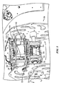
[0029]図1は、本開示の一態様による独立ワイルドスワーブ駆動ポッド100の一例を示す。独立ワイルドスワーブ駆動ポッド100は駆動ポッドと呼ばれ得る。図1に示すように、3つのモーター102、104、106がハウジング120内に画定され得る。駆動歯車110が各モーター102、104、106に結合され得る。図1に示すように、第1のモーター102および第3のモーター106の駆動歯車110は、駆動軸歯車112を含んだハウジング120の第1の表面上に画定されている。第2のモーター104の駆動歯車(図示せず)は、駆動ポッド100の第1の表面とは異なる、ハウジング120の第2の表面上に画定され得る。
[0029] FIG. 1 illustrates an example of an independent wild
[0030]第1のモーター102および第3のモーター106の駆動歯車110は、駆動歯車116の駆動軸歯車112を回転させる。図1に示すように、駆動軸116は六角軸であり得る。さらに、第2のモーター104の駆動歯車はカルーセル114を回転させ得る。すなわち、第2のモーター104の駆動歯車110は、カルーセル114を右および/または左に回転させるカルーセル歯車(図示せず)を駆動するように指定される。カルーセル114は、車輪(図示せず)用の輪軸(図示せず)を収容する。さらに、第1のモーター102および第3のモーター106の駆動歯車110は、駆動軸116を介して車輪を順方向および/または逆方向に回転させる。カルーセル114は、ハウジング120から独立して回転する。すなわち、一構成では、ハウジング120は、カルーセル114が右方向および/または左方向に回転する間も静止している。
[0030] The drive gears 110 of the
[0031]さらに、図1に示すように、駆動軸116は、駆動ポッド100から垂直方向に延びている。より具体的には、図1には図示されていないが、駆動ポッド100は、駆動ポッドの輪軸に結合される車輪の間に画定されるように構成され、そのため、駆動軸116のみが車輪の平面を越えてまたは車輪の平面に実質的に平行に延びるようになっている。駆動軸116は、駆動ポッド100をロボットのアーム(図示せず)と結合するために使用される単一の取付軸(図示せず)に結合され得る。
Further, as shown in FIG. 1, the
[0032]別の構成では、単一の取付軸は直接、駆動ポッドに結合される。一構成では、ロボットのモーターおよび/または歯車を制御するための配線は、単一の取付軸を通じて供給される。さらに、駆動ポッドが解放機構を介してロボットのアームから解放され得るように、解放機構が単一の取付軸上に画定され得る。 [0032] In another configuration, a single mounting shaft is directly coupled to the drive pod. In one configuration, the wiring for controlling the robot's motor and / or gears is provided through a single mounting shaft. Further, the release mechanism can be defined on a single mounting axis so that the drive pod can be released from the robot arm via the release mechanism.
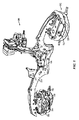
[0033]図2は、本開示の一態様による駆動ポッド200を示す。図2に示すように、駆動ポッド200は、ハウジング214と、そのハウジング214に結合されたカルーセル212とを含み得る。一構成では、ハウジング214は、複数の歯車箱224、226とモーター228、230とを収容するために使用される。モーター228、230および歯車箱224、226は、様々な歯車216、218、220、222に結合される。たとえば、第1のモーター228は第1の駆動歯車216を駆動する。第1の駆動歯車216は、第1の歯車箱224に結合されている第1の歯車箱歯車218と結合され得る。歯車箱224、226は、車輪の速度および/またはトルクを制御するために、異なる歯車構成をもたらし得る。前に説明したように、ハウジング214内に画定された歯車216、218、220、222のうちのいくつかは、駆動軸(図示せず)の駆動軸歯車208を駆動する。駆動軸は差動装置206に結合される。
[0033] FIG. 2 illustrates a
[0034]図2に示すように、差動装置206は、カルーセル212内に収容されており、車輪210に結合されている輪軸202を駆動する。すなわち、第1のモーター228および1つまたは複数の他のモーター(図示せず)は、車輪210が順方向および/または逆方向に進み得るように、輪軸202を駆動する駆動軸を駆動する。駆動軸は、ハウジング214に結合されている駆動軸歯車208を介して駆動される。
As shown in FIG. 2, the differential 206 is housed in the carousel 212 and drives a
[0035]さらに、図2に示すように、駆動ポッド200はまた、ハウジング214内に画定された第2のモーター230を含み得る。第2のモーター230は第2の駆動歯車222を駆動する。一構成では、第2の駆動歯車222は、第2の歯車箱226の第2の歯車箱歯車220に結合される。第2の歯車箱歯車220は、カルーセル212のカルーセル歯車204の回転の速度および/またはトルクを制御するために、第2の駆動歯車222とともに使用され得る。さらに、第2の歯車箱歯車220は、カルーセル212が右方向および/または左方向に進み得るように、カルーセル212のカルーセル歯車204を駆動する。カルーセル212の運動は、駆動ポッド200を右および/または左に回転させる。
In addition, as shown in FIG. 2, the
[0036]図3は、本開示の一態様による駆動ポッド300を示す。図3に示すように、駆動ポッド300は、ハウジング312と、そのハウジング312に結合されたカルーセル320とを含み得る。一構成では、ハウジング312は、様々な駆動歯車308、314、326に結合される複数のモーター302、304、306を収容する。
[0036] FIG. 3 illustrates a
[0037]一構成では、第1のモーター302は第1の駆動歯車314を駆動するように指定される。第1の駆動歯車314は、カルーセル320に結合されているカルーセル歯車322と結合され得る。第1の駆動歯車314は、図3の方向矢印で示すように、カルーセル320が右方向および/または左方向に回転し得るようにカルーセル歯車322を駆動する。
[0037] In one configuration, the
[0038]カルーセル320はまた、車輪324に結合されている輪軸316を収容する。さらに、カルーセル320は、輪軸316および駆動軸(図示せず)に結合されている差動装置318を収容する。前に説明したように、ハウジング312内に画定された歯車308、326のうちのいくつかは、差動装置318に結合されている駆動軸(図示せず)の駆動軸歯車310を駆動する。差動装置318は、車輪324に結合されている輪軸316を駆動するように指定される。すなわち、第2のモーター304および第3のモーター306は、図3の方向矢印で示すように車輪324が順方向または逆方向に進み得るように、輪軸316を駆動する駆動軸に回転をもたらす。駆動軸は、ハウジング312に結合されている駆動軸歯車310を介して駆動される。より具体的には、第2のモーター304の第2の駆動歯車326および第3のモーター306の第3の駆動歯車308が駆動軸歯車310に結合される。
[0038] The
[0039]図4は、本開示の一態様による、ロボット400の一例を示す。図4に示すように、ロボット400は、3つの独立駆動ポッド402を含んでいる。ロボット400に移動をもたらすように、2つの車輪404が各駆動ポッド402に結合され得る。すなわち、車輪404は、各駆動ポッド402内に設けられたモーター(図示せず)に基づいて、順方向または逆方向に進み得る。さらに、各駆動ポッド402は、各駆動ポッド402内に設けられたモーターに基づいて、左または右に回転し得る。したがって、各駆動ポッド402のカルーセル(図示せず)が右回転および/または左回転するとともに、車輪404が順回転/逆回転することにより、ロボット400は、順方向、逆方向など様々な方向に進み、左に回転し、右に回転し、左に旋回し、右に旋回することが可能になる。
[0039] FIG. 4 illustrates an example of a
[0040]さらに、図4に示すように、各駆動ポッド402は、ロボット400のアーム406に結合され得る。アーム406および駆動ポッド402は、駆動ポッド402の取替え/再構成を改善するために、各駆動ポッド402がアーム406から切り離され得るように構成され得る。加えて、アーム406は、ロボット本体408に結合されている。ロボット本体408は、ロボット400を制御するために、電子機器と、モーターと、他のデバイス(図示せず)とを収容し得る。さらに、他のアタッチメント(図示せず)がロボット本体408に結合され得る。一構成では、図4に示すように、延長可能なアーム412およびクロー410がロボット本体408に結合され得る。
Further, as shown in FIG. 4, each
[0041]さらに、図4に示すように、各駆動ポッド402は、2つの車輪404の間に画定され、そのため、駆動ポッド402に結合されるモーターおよび歯車が1対の車輪404内に画定されるようになっている。さらに、単一の取付軸(図示せず)が、ロボット400のアーム406と連結するように、駆動ポッド402から延びている。具体的に言うと、図4に示すように、2つの車輪404の間の空間は、駆動ポッド402がロボット400のアーム406に結合されるように、単一の取付軸が2つの車輪404の空間の間で延びることを可能にしている。
Further, as shown in FIG. 4, each
[0042]図5は、本開示の一態様による、ロボット500の一例を示す。図5に示すように、ロボット500は、3つの駆動ポッド502を含んでいる。一構成では、2つの車輪(図示せず)が各駆動ポッド502に結合され得る。車輪はロボット500に移動をもたらす。さらに、各駆動ポッド502は、カルーセル510とハウジング520とからなる。車輪は、各ハウジング520内に設けられた駆動モーター504に基づいて、順方向または逆方向に進み得る。具体的に言うと、車輪は、駆動軸(図示せず)によって駆動される(すなわち、回転する)輪軸506に結合される。駆動軸は、ハウジング520内に画定された駆動歯車508および駆動モーター504によって駆動される。
[0042] FIG. 5 illustrates an example of a
[0043]一構成では、各ハウジング520に結合されたカルーセル510が、各ハウジング520内に設けられたカルーセルモーター512およびカルーセル歯車(図示せず)に基づいて、左および/または右に回転し得る。カルーセル510を右および/または左に回転させるカルーセルモーター512およびカルーセル歯車は、車輪を順方向/逆方向に回転させる駆動歯車508および駆動モーター504とは異なるものである。各カルーセル510が右回転および/または左回転するとともに、車輪が順回転/逆回転することにより、ロボット500は、順方向、逆方向など様々な方向に進み、左に回転し、右に回転し、左に旋回し、右に旋回することが可能になる。カルーセル510が右および/または左に進む間も各ハウジング520は静止したままであることに留意されたい。
[0043] In one configuration, a
[0044]また、一構成では、駆動軸は、カルーセル歯車のベアリング(図示せず)を通過する六角軸であることに留意されたい。具体的に言うと、ベアリングはカルーセル510を取り付けるものであり、駆動軸が輪軸506を駆動しているときに誤ってカルーセル510の向きを変えさせることなく駆動軸の回転を可能にする。
[0044] It should also be noted that in one configuration, the drive shaft is a hexagonal shaft that passes through a carousel gear bearing (not shown). Specifically, the bearing attaches the
[0045]さらに、図5に示すように、各駆動ポッド502は、ロボット500のアーム514に結合され得る。アーム514および駆動ポッド502は、各駆動ポッド502の取替え/再構成を改善するために、駆動ポッド502がアーム514から独立して切り離され得るように構成され得る。加えて、アーム514は、ロボット本体516に結合されている。ロボット本体516は、ロボット500を制御するために使用される電子機器と、モーターと、他のデバイス(図示せず)とを収容し得る。
Further, as shown in FIG. 5, each
[0046]本開示の態様は、同じ方向に進む駆動ポッドの両方の車輪について説明するものであったが、本開示はまた、種々のモーター/歯車の構成、独立した輪軸、別々の駆動軸などに基づいた、独立した車輪の回転をも企図する。すなわち、車輪の一方の半球体(たとえば、左の半球体)は、もう一方の半球体(たとえば、右の半球体)が反対方向に進む間にも、一方向に進み得る。 [0046] Although aspects of the present disclosure described both wheels of a drive pod traveling in the same direction, the present disclosure also includes various motor / gear configurations, independent wheel shafts, separate drive shafts, etc. Independent wheel rotation based on the above is also contemplated. That is, one hemisphere (eg, the left hemisphere) of the wheel can travel in one direction while the other hemisphere (eg, the right hemisphere) travels in the opposite direction.
[0047]図6は、本開示の態様による、ロボットを自律的に制御するためのブロック図600を示す。ブロック602に示すように、ロボットは、1つまたは複数の駆動軸を駆動するように1つまたは複数の第1の歯車を制御する。さらに、ブロック604に示すように、ロボットは、1つまたは複数のカルーセル歯車を駆動するように1つまたは複数の第2の歯車を制御する。
[0047] FIG. 6 shows a block diagram 600 for autonomously controlling a robot according to aspects of the present disclosure. As shown in
[0048]一構成では、独立ワイルドスワーブ駆動ポッド100などの駆動ポッドが、制御するための手段を含んだロボットデバイスを制御するように構成される。一態様では、制御する手段は、制御する手段によって具陳された機能を実施するように構成されたモーター102、104、106、228、230、302、304、306、504、512および/または歯車箱224、226であり得る。別の構成では、上述の手段は、上述の手段によって具陳された機能を実行するように構成された任意のモジュールまたは任意の装置であり得る。
[0048] In one configuration, a drive pod, such as independent wild
[0049]上述の方法の様々な動作は、対応する機能を実施することができる任意の好適な手段によって実施され得る。それらの手段は、限定はされないが、回路、特定用途向け集積回路(ASIC)、またはプロセッサを含む、様々な(1つまたは複数の)ハードウェアおよび/またはソフトウェア構成要素および/またはモジュールを含み得る。一構成では、ロボットデバイスは、制御するための手段を含む。制御する手段は、図1〜5に示したモーターおよび/または歯車箱であり得る。別の構成では、上述の手段は、上述の手段によって具陳された機能を実施するように構成された任意のモジュールまたは任意の装置であり得る。概して、図に示されている動作が存在する場合、それらの動作は、同様の番号をもつ対応するカウンターパートのミーンズプラスファンクション構成要素を有し得る。 [0049] Various operations of the methods described above may be performed by any suitable means capable of performing corresponding functions. Such means may include various (one or more) hardware and / or software components and / or modules including, but not limited to, circuits, application specific integrated circuits (ASICs), or processors. . In one configuration, the robotic device includes means for controlling. The means for controlling can be the motor and / or gearbox shown in FIGS. In another configuration, the means described above may be any module or any device configured to perform the function provided by the means described above. In general, if the operations shown in the figures are present, they may have corresponding counterpart means-plus-function components with similar numbers.
[0050]本明細書で使用される「決定すること」という用語は、様々な活動を包含する。たとえば、「決定すること」は、計算すること、算出すること、処理すること、導出すること、調査すること、探索すること(たとえば、テーブル、データベース、または別のデータ構造の中で探索すること)、確認することなどを含み得る。加えて、「決定すること」は、受信すること(たとえば、情報を受信すること)、アクセスすること(たとえば、メモリ中のデータにアクセスすること)などを含み得る。さらに、「決定すること」は、解決すること、選択すること、選定すること、確立することなどを含み得る。 [0050] As used herein, the term "determining" encompasses a variety of activities. For example, “determining” means calculating, calculating, processing, deriving, exploring, searching (eg searching within a table, database, or another data structure) ), Confirmation, etc. In addition, “determining” may include receiving (eg, receiving information), accessing (eg, accessing data in a memory) and the like. Further, “determining” may include resolving, selecting, selecting, establishing and the like.
[0051]本明細書で使用される項目のリスト「のうちの少なくとも1つ」を指す句は、単一のメンバーを含む、それらの項目の任意の組合せを指す。一例として、「a、b、またはcのうちの少なくとも1つ」は、aと、bと、cと、a-bと、a-cと、b-cと、a-b-cとを包含するものとする。 [0051] As used herein, a phrase referring to "at least one of" a list of items refers to any combination of those items, including a single member. As an example, “at least one of a, b, or c” includes a, b, c, ab, ac, bc, and abc. It shall be included.
[0052]本開示に関して説明した様々な例示的な論理ブロック、モジュール、および回路は、汎用プロセッサ、デジタル信号プロセッサ(DSP)、特定用途向け集積回路(ASIC)、フィールドプログラマブルゲートアレイ信号(FPGA)もしくは他のプログラマブル論理デバイス(PLD)、個別ゲートもしくはトランジスタ論理、個別ハードウェア構成要素、または本明細書で説明する機能を実施するように設計されたそれらの任意の組合せによって実装または実施され得る。汎用プロセッサはマイクロプロセッサであり得るが、代替として、プロセッサは、任意の市販のプロセッサ、コントローラ、マイクロコントローラ、または状態機械であり得る。プロセッサはまた、コンピューティングデバイスの組合せ、たとえば、DSPとマイクロプロセッサの組合せ、複数のマイクロプロセッサ、DSPコアと連携する1つまたは複数のマイクロプロセッサ、あるいは任意の他のそのような構成として実装され得る。 [0052] Various exemplary logic blocks, modules, and circuits described in connection with this disclosure may be general purpose processors, digital signal processors (DSPs), application specific integrated circuits (ASICs), field programmable gate array signals (FPGAs) or It may be implemented or implemented by other programmable logic devices (PLDs), individual gate or transistor logic, individual hardware components, or any combination thereof designed to perform the functions described herein. A general purpose processor may be a microprocessor, but in the alternative, the processor may be any commercially available processor, controller, microcontroller or state machine. The processor may also be implemented as a combination of computing devices, eg, a DSP and microprocessor combination, a plurality of microprocessors, one or more microprocessors associated with a DSP core, or any other such configuration. .
[0053]本開示に関連して説明した方法またはアルゴリズムのステップは、ハードウェアで直接実施されるか、プロセッサによって実行されるソフトウェアモジュールで実施されるか、またはその2つの組合せで実施され得る。ソフトウェアモジュールは、当技術分野で知られている任意の形態の記憶媒体中に常駐し得る。使用され得る記憶媒体のいくつかの例としては、ランダムアクセスメモリ(RAM)、読取り専用メモリ(ROM)、フラッシュメモリ、消去可能プログラマブル読取り専用メモリ(EPROM)、電気消去可能プログラマブル読取り専用メモリ(EEPROM(登録商標))、レジスタ、ハードディスク、リムーバブルディスク、CD−ROMなどがある。ソフトウェアモジュールは、単一の命令または多数の命令を備え得、いくつかの異なるコードセグメント上で、異なるプログラム間で、および複数の記憶媒体にわたって分散され得る。記憶媒体は、プロセッサがその記憶媒体から情報を読み取り、その記憶媒体に情報を書き込むことができるように、プロセッサに結合され得る。代替として、記憶媒体はプロセッサと一体であり得る。 [0053] The method or algorithm steps described in connection with this disclosure may be implemented directly in hardware, in a software module executed by a processor, or in a combination of the two. A software module may reside in any form of storage medium that is known in the art. Some examples of storage media that may be used include random access memory (RAM), read only memory (ROM), flash memory, erasable programmable read only memory (EPROM), electrically erasable programmable read only memory (EEPROM ( Registered trademark)), registers, hard disks, removable disks, CD-ROMs, and the like. A software module may comprise a single instruction or multiple instructions and may be distributed over several different code segments, between different programs, and across multiple storage media. A storage medium may be coupled to the processor such that the processor can read information from, and write information to, the storage medium. In the alternative, the storage medium may be integral to the processor.
[0054]本明細書で開示した方法は、説明した方法を達成するための1つまたは複数のステップまたはアクションを備える。本方法のステップおよび/またはアクションは、特許請求の範囲から逸脱することなく互いに交換され得る。言い換えれば、ステップまたはアクションの特定の順序が指定されていない限り、特定のステップおよび/またはアクションの順序および/または使用は、特許請求の範囲から逸脱することなく、変更され得る。 [0054] The methods disclosed herein comprise one or more steps or actions for achieving the described method. The method steps and / or actions may be interchanged with one another without departing from the scope of the claims. In other words, unless a specific order of steps or actions is specified, the order and / or use of specific steps and / or actions may be changed without departing from the scope of the claims.
[0055]上述の機能は、ハードウェア、ソフトウェア、ファームウェア、またはそれらの任意の組合せにおいて実装され得る。ハードウェアで実装される場合、例示的なハードウェア構成はデバイス中に処理システムを備え得る。処理システムは、バスアーキテクチャを用いて実装され得る。バスは、処理システムの特定の適用例および全体的な設計制約に応じて、任意の数の相互接続バスとブリッジとを含み得る。バスは、プロセッサと、機械可読媒体と、バスインターフェースとを含む様々な回路を互いにリンクし得る。バスインターフェースは、ネットワークアダプタを、特に、バスを介して処理システムに接続するために使用され得る。ネットワークアダプタは、信号処理機能を実装するために使用され得る。いくつかの態様では、ユーザインターフェース(たとえば、キーパッド、ディスプレイ、マウス、ジョイスティックなど)もバスに接続され得る。バスはまた、タイミングソース、周辺機器、電圧調整器、電力管理回路などの様々な他の回路をリンクし得るが、それらは当技術分野でよく知られており、したがってこれ以上は説明されない。 [0055] The functions described above may be implemented in hardware, software, firmware, or any combination thereof. When implemented in hardware, an exemplary hardware configuration may comprise a processing system in the device. The processing system can be implemented using a bus architecture. The bus may include any number of interconnect buses and bridges depending on the specific application of the processing system and the overall design constraints. The bus may link various circuits including a processor, a machine readable medium, and a bus interface to each other. The bus interface can be used to connect the network adapter, in particular, to the processing system via the bus. Network adapters can be used to implement signal processing functions. In some aspects, a user interface (eg, keypad, display, mouse, joystick, etc.) may also be connected to the bus. The bus may also link various other circuits such as timing sources, peripherals, voltage regulators, power management circuits, etc., which are well known in the art and are therefore not further described.
[0056]プロセッサは、機械可読媒体に格納されたソフトウェアの実行を含む、バスおよび一般的な処理を管理することを担い得る。プロセッサは、1つまたは複数の汎用および/または専用プロセッサを用いて実装され得る。例としては、マイクロプロセッサ、マイクロコントローラ、DSPプロセッサ、およびソフトウェアを実行し得る他の回路を含む。ソフトウェアは、ソフトウェア、ファームウェア、ミドルウェア、マイクロコード、ハードウェア記述言語などの名称にかかわらず、命令、データ、またはそれらの任意の組合せを意味すると広く解釈されたい。機械可読媒体は、例として、ランダムアクセスメモリ(RAM)、フラッシュメモリ、読取り専用メモリ(ROM)、プログラマブル読取り専用メモリ(PROM)、消去可能プログラマブル読取り専用メモリ(EPROM)、電気消去可能プログラマブル読取り専用メモリ(EEPROM)、レジスタ、磁気ディスク、光ディスク、ハードドライブ、もしくは任意の他の好適な記憶媒体、またはそれらの任意の組合せを含み得る。機械可読媒体はコンピュータプログラム製品において実施され得る。コンピュータプログラム製品はパッケージング材料を備え得る。 [0056] The processor may be responsible for managing buses and general processing, including execution of software stored on machine-readable media. The processor may be implemented using one or more general purpose and / or dedicated processors. Examples include microprocessors, microcontrollers, DSP processors, and other circuits that can execute software. Software should be broadly interpreted to mean instructions, data, or any combination thereof, regardless of names such as software, firmware, middleware, microcode, hardware description language, and the like. Machine-readable media include, for example, random access memory (RAM), flash memory, read only memory (ROM), programmable read only memory (PROM), erasable programmable read only memory (EPROM), electrically erasable programmable read only memory (EEPROM), register, magnetic disk, optical disk, hard drive, or any other suitable storage medium, or any combination thereof. A machine-readable medium may be implemented in a computer program product. The computer program product may comprise packaging material.
[0057]ハードウェア実装形態では、機械可読媒体は、プロセッサとは別個の処理システムの一部であり得る。しかしながら、当業者が容易に理解するように、機械可読媒体またはその任意の部分は処理システムの外部に存在し得る。例として、機械可読媒体は、すべてバスインターフェースを介してプロセッサによってアクセスされ得る、伝送線路、データによって変調された搬送波、および/またはデバイスとは別個のコンピュータ製品を含み得る。代替的に、または追加で、機械可読媒体またはその任意の部分は、キャッシュおよび/または汎用レジスタファイルがそうであり得るように、プロセッサに統合され得る。ローカルな構成要素など、説明した様々な構成要素は、特定のロケーションを有するものとして説明され得るが、それらはまた、分散計算システムの一部として構成されている特定の構成要素などのように、様々な方式で構成され得る。 [0057] In a hardware implementation, the machine-readable medium may be part of a processing system that is separate from the processor. However, as those skilled in the art will readily appreciate, the machine-readable medium or any portion thereof may be external to the processing system. By way of illustration, a machine-readable medium may include a transmission line, a data modulated carrier wave, and / or a computer product separate from the device, all of which may be accessed by a processor via a bus interface. Alternatively or additionally, the machine-readable medium or any portion thereof may be integrated into the processor, as may the cache and / or general purpose register file. While the various components described, such as local components, may be described as having a particular location, they may also be described as specific components configured as part of a distributed computing system, etc. It can be configured in various ways.
[0058]処理システムは、すべて外部バスアーキテクチャを介して他のサポート回路と互いにリンクされる、プロセッサ機能を実現する1つまたは複数のマイクロプロセッサと、機械可読媒体の少なくとも一部分を構成する外部メモリとをもつ汎用処理システムとして構成され得る。代替的に、処理システムは、本明細書で説明した神経モデルと神経系のモデルとを実装するための1つまたは複数の神経形態学的プロセッサを備え得る。別の代替として、処理システムは、プロセッサをもつ特定用途向け集積回路(ASIC)と、バスインターフェースと、ユーザインターフェースと、サポート回路と、単一のチップに統合された機械可読媒体の少なくとも一部分とを用いて、あるいは1つまたは複数のフィールドプログラマブルゲートアレイ(FPGA)、プログラマブル論理デバイス(PLD)、コントローラ、状態機械、ゲート論理、個別ハードウェア構成要素、もしくは他の好適な回路、または本開示全体にわたって説明した様々な機能を実行し得る回路の任意の組合せを用いて、実装され得る。当業者には、具体的な適用例と、全体的なシステムに課される全体的な設計制約とに応じて、処理システムについて記載された機能性を最適に実装する方法が認識されよう。 [0058] The processing system includes one or more microprocessors that implement processor functionality, all linked together with other support circuitry via an external bus architecture, and an external memory that forms at least a portion of the machine-readable medium. Can be configured as a general-purpose processing system. Alternatively, the processing system may comprise one or more neuromorphological processors for implementing the neural models and models of the nervous system described herein. As another alternative, a processing system includes an application specific integrated circuit (ASIC) having a processor, a bus interface, a user interface, support circuitry, and at least a portion of a machine readable medium integrated on a single chip. Or one or more field programmable gate arrays (FPGAs), programmable logic devices (PLDs), controllers, state machines, gate logic, discrete hardware components, or other suitable circuitry, or throughout this disclosure It can be implemented using any combination of circuits that can perform the various functions described. Those skilled in the art will recognize how to optimally implement the functionality described for a processing system, depending on the specific application and the overall design constraints imposed on the overall system.
[0059]機械可読媒体はいくつかのソフトウェアモジュールを備え得る。ソフトウェアモジュールは、プロセッサによって実行されたときに、処理システムに様々な機能を実施させる命令を含む。ソフトウェアモジュールは、送信モジュールと受信モジュールとを含み得る。各ソフトウェアモジュールは、単一の記憶デバイス中に常駐するか、または複数の記憶デバイスにわたって分散され得る。例として、トリガイベントが発生したとき、ソフトウェアモジュールがハードドライブからRAMにロードされ得る。ソフトウェアモジュールの実行中、プロセッサは、アクセス速度を高めるために、命令のいくつかをキャッシュにロードし得る。次いで、1つまたは複数のキャッシュラインが、プロセッサによる実行のために汎用レジスタファイルにロードされ得る。以下でソフトウェアモジュールの機能性に言及する場合、そのような機能性は、そのソフトウェアモジュールからの命令を実行したときにプロセッサによって実装されることが理解されよう。 [0059] A machine-readable medium may comprise a number of software modules. A software module includes instructions that, when executed by a processor, cause the processing system to perform various functions. The software module may include a transmission module and a reception module. Each software module can reside in a single storage device or can be distributed across multiple storage devices. As an example, a software module can be loaded from a hard drive into RAM when a trigger event occurs. During execution of the software module, the processor may load some of the instructions into the cache to increase access speed. One or more cache lines can then be loaded into a general purpose register file for execution by the processor. When referring to the functionality of a software module below, it will be understood that such functionality is implemented by a processor when executing instructions from that software module.
[0060]ソフトウェアで実装される場合、機能は、1つもしくは複数の命令もしくはコードとしてコンピュータ可読媒体上に記憶されるか、またはコンピュータ可読媒体を介して送信され得る。コンピュータ可読媒体は、ある場所から別の場所へのコンピュータプログラムの転送を容易にするすべての媒体を含む、通信媒体とコンピュータ記憶媒体との両方を含む。記憶媒体は、コンピュータによってアクセスされ得る、任意の利用可能な媒体であってよい。限定でなく例として、そのようなコンピュータ可読媒体は、RAM、ROM、EEPROM、CD−ROMもしくは他の光ディスク記憶装置、磁気ディスク記憶装置もしくは他の磁気記憶デバイス、または所望のプログラムコードを命令もしくはデータ構造の形式で搬送もしくは記憶するために使用され得、コンピュータによってアクセスされ得る、他の任意の媒体を備え得る。さらに、いかなる接続もコンピュータ可読媒体と適切に呼ばれる。たとえば、ソフトウェアが、同軸ケーブル、光ファイバーケーブル、ツイストペア、デジタル加入者回線(DSL)、または赤外線(IR)、無線、およびマイクロ波などのワイヤレス技術を使用して、ウェブサイト、サーバ、または他のリモートソースから送信される場合、同軸ケーブル、光ファイバーケーブル、ツイストペア、DSL、または赤外線、無線、およびマイクロ波などのワイヤレス技術は、媒体の定義に含まれる。本明細書で使用するディスク(disk)およびディスク(disc)は、コンパクトディスク(disc)(CD)、レーザーディスク(登録商標)(disc)、光ディスク(disc)、デジタル多用途ディスク(disc)(DVD)、フロッピー(登録商標)ディスク(disk)、およびBlu−ray(登録商標)ディスク(disc)を含み、ディスク(disk)は、通常、データを磁気的に再生し、ディスク(disc)は、データをレーザーで光学的に再生する。したがって、いくつかの態様では、コンピュータ可読媒体は、非一時的コンピュータ可読媒体(たとえば、有形媒体)を備え得る。さらに、他の態様では、コンピュータ可読媒体は一時的コンピュータ可読媒体(たとえば、信号)を備え得る。上の組合せもコンピュータ可読媒体の範囲内に含まれるべきである。 [0060] When implemented in software, the functions may be stored on or transmitted over as one or more instructions or code on a computer-readable medium. Computer-readable media includes both communication media and computer storage media including any medium that facilitates transfer of a computer program from one place to another. A storage media may be any available media that can be accessed by a computer. By way of example, and not limitation, such computer-readable media may include RAM, ROM, EEPROM, CD-ROM or other optical disk storage, magnetic disk storage or other magnetic storage device, or instructions or data with desired program code. Any other medium that can be used to transport or store in the form of a structure and that can be accessed by a computer can be provided. In addition, any connection is properly referred to as a computer-readable medium. For example, the software may use a website, server, or other remote, using coaxial technology, fiber optic cable, twisted pair, digital subscriber line (DSL), or wireless technologies such as infrared (IR), wireless, and microwave. When transmitted from a source, coaxial cable, fiber optic cable, twisted pair, DSL, or wireless technologies such as infrared, radio, and microwave are included in the definition of the medium. As used herein, a disk and a disc are a compact disc (CD), a laser disc (registered trademark) (disc), an optical disc (disc), a digital versatile disc (DVD). ), Floppy (R) disk, and Blu-ray (R) disc, the disk normally reproducing data magnetically, and the disc is data Is optically reproduced with a laser. Thus, in some aspects computer readable media may comprise non-transitory computer readable media (eg, tangible media). In addition, in other aspects computer readable media may comprise transitory computer readable media (eg, signals). Combinations of the above should also be included within the scope of computer-readable media.
[0061]したがって、いくつかの態様は、本明細書で提示された動作を実行するためのコンピュータプログラム製品を備え得る。たとえば、そのようなコンピュータプログラム製品は、本明細書で説明された動作を実行するために1つまたは複数のプロセッサによって実行可能である命令をその上に記憶した(および/または符号化した)コンピュータ可読媒体を備え得る。いくつかの態様では、コンピュータプログラム製品はパッケージング材料を含み得る。 [0061] Accordingly, some aspects may comprise a computer program product for performing the operations presented herein. For example, such a computer program product stores a computer (and / or encoded) with instructions stored thereon that can be executed by one or more processors to perform the operations described herein. A readable medium may be provided. In some aspects, the computer program product may include packaging material.
[0062]さらに、本明細書で説明された方法と技法とを実行するためのモジュールおよび/または他の適切な手段は、適宜、ユーザ端末および/または基地局によってダウンロードされ、および/または他の方法で取得され得ることを諒解されたい。たとえば、本明細書で説明された方法を実行するための手段の転送を可能にするために、そのようなデバイスはサーバに結合され得る。代替的に、本明細書で説明された様々な方法は、ユーザ端末および/または基地局が記憶手段をデバイスに結合するかまたは与えると様々な方法を得ることができるように、記憶手段(たとえば、RAM、ROM、コンパクトディスク(CD)またはフロッピーディスクなど物理記憶媒体など)によって提供され得る。さらに、本明細書に記載された方法と技法とをデバイスに供給するための任意の他の好適な技法が利用され得る。 [0062] Further, modules and / or other suitable means for performing the methods and techniques described herein may be downloaded by user terminals and / or base stations, as appropriate, and / or other Please understand that it can be obtained in a way. For example, such a device can be coupled to a server to allow transfer of means for performing the methods described herein. Alternatively, the various methods described herein may be stored in a storage means (e.g., a user terminal and / or a base station may obtain the various methods when the storage means is coupled to or provided with the device) RAM, ROM, a physical storage medium such as a compact disk (CD) or a floppy disk, etc.). Moreover, any other suitable technique for supplying the devices with the methods and techniques described herein may be utilized.
[0063]特許請求の範囲は、上で示された厳密な構成および構成要素に限定されないことを理解されたい。上記で説明した方法および装置の配置、動作、および詳細において、特許請求の範囲から逸脱することなく、様々な修正、変更、および変形が行われる場合がある。 [0063] It is to be understood that the claims are not limited to the precise configuration and components illustrated above. Various modifications, changes and variations may be made in the arrangement, operation and details of the methods and apparatus described above without departing from the scope of the claims.
[0063]特許請求の範囲は、上で示された厳密な構成および構成要素に限定されないことを理解されたい。上記で説明した方法および装置の配置、動作、および詳細において、特許請求の範囲から逸脱することなく、様々な修正、変更、および変形が行われる場合がある。
以下に、本願出願の当初の特許請求の範囲に記載された発明を付記する。
[C1]
ロボットデバイスであって、
駆動ポッドの輪軸に結合された複数の車輪の間に画定された駆動ポッドと、
前記駆動ポッドに結合されており、前記駆動ポッドを前記ロボットデバイスの本体と結合するように構成されている単一の取付軸と、
前記駆動ポッド内に画定されており、前記駆動ポッドの駆動軸歯車に結合された複数の第1の駆動歯車を制御するように構成されている複数の第1のモーターと、
前記駆動ポッド内に画定されており、前記駆動ポッドのカルーセル歯車に結合された第2の駆動歯車を制御するように構成されている第2のモーターと、を備える前記ロボットデバイス。
[C2]
前記駆動ポッドの駆動軸に結合された差動装置をさらに備え、前記差動装置は前記輪軸を駆動するように構成されている、C1に記載のロボットデバイス。
[C3]
前記複数の第1の駆動歯車は、前記駆動軸歯車を駆動するように構成されており、
前記駆動軸歯車は、前記複数の車輪が順方向または逆方向に回転するように、前記駆動軸を駆動するように構成されている、C2に記載のロボットデバイス。
[C4]
前記駆動ポッドに結合されており、前記輪軸と前記差動装置とを収容するように構成されているカルーセル、前記カルーセル歯車は前記カルーセルに結合されている、をさらに備える、C3に記載のロボットデバイス。
[C5]
前記第2の駆動歯車は、前記順方向に対して実質的に直角の少なくとも1つの方向に前記カルーセルを回転させるよう、前記カルーセル歯車を駆動するように構成されている、C4に記載のロボットデバイス。
[C6]
前記単一の取付軸は前記本体のアームに結合されている、C1に記載のロボットデバイス。
[C7]
複数の駆動ポッドをさらに備える、C1に記載のロボットデバイス。
[C8]
複数の歯車箱をさらに備え、各歯車箱は、少なくとも前記複数の第1の駆動歯車または前記第2の駆動歯車の少なくとも速度、トルク、またはそれらの組合せを制御するように構成された少なくとも1つの歯車箱歯車に結合されている、C1に記載のロボットデバイス。
[C9]
ロボットデバイスを制御する方法であって、
駆動ポッドの駆動軸歯車に結合された複数の第1の駆動歯車を制御するように前記駆動ポッド内で複数の第1のモーターを制御することと、
前記駆動ポッドのカルーセル歯車に結合された第2の駆動歯車を制御するように前記駆動ポッド内で第2のモーターを制御することと、前記駆動ポッドは、複数の車輪の間に配置されており、単一の取付軸を介して前記ロボットデバイスに結合されている、を備える方法。
[C10]
前記複数の第1の駆動歯車によって前記駆動軸歯車を駆動することと、
前記複数の車輪が順方向または逆方向に回転するように駆動軸を駆動することと、をさらに備える、C9に記載の方法。
[C11]
輪軸を駆動するように差動装置を駆動することをさらに備える、C10に記載の方法。
[C12]
前記順方向に対して実質的に直角の少なくとも1つの方向にカルーセルを回転させるように前記第2の駆動歯車によって前記カルーセル歯車を駆動することをさらに備える、C11に記載の方法。
[C13]
ロボットデバイスを制御するための装置であって、
駆動ポッド内で、前記駆動ポッドの駆動軸歯車に結合された複数の第1の駆動歯車を制御するための手段と、
前記駆動ポッド内で、前記駆動ポッドのカルーセル歯車に結合された第2の駆動歯車を制御するための手段と、前記駆動ポッドは、複数の車輪の間に配置されており、単一の取付軸を介して前記ロボットデバイスに結合されている、を備える装置。
[C14]
前記駆動軸歯車を駆動するための手段と、
前記複数の車輪が順方向または逆方向に回転するように駆動軸を駆動するための手段と、をさらに備える、C13に記載の装置。
[C15]
輪軸を駆動するように差動装置を駆動するための手段をさらに備える、C14に記載の装置。
[C16]
前記順方向に対して実質的に直角の少なくとも1つの方向にカルーセルを回転させるように前記カルーセル歯車を駆動するための手段をさらに備える、C15に記載の装置。
[C17]
ロボットデバイスを制御するためのコンピュータプログラム製品であって、
プログラムコードを記録した非一時的コンピュータ可読媒体を備え、前記プログラムコードは、
駆動ポッドの駆動軸歯車に結合された複数の第1の駆動歯車を制御するように前記駆動ポッド内で複数の第1のモーターを制御するためのプログラムコードと、
前記駆動ポッドのカルーセル歯車に結合された第2の駆動歯車を制御するように前記駆動ポッド内で第2のモーターを制御するためのプログラムコードと、前記駆動ポッドは、複数の車輪の間に配置されており、単一の取付軸を介して前記ロボットデバイスに結合されている、を備えるコンピュータプログラム製品。
[C18]
前記プログラムコードは、
前記複数の第1の駆動歯車によって前記駆動軸歯車を駆動するためのプログラムコードと、
前記複数の車輪が順方向または逆方向に回転するように駆動軸を駆動するためのプログラムコードと、をさらに備える、C17に記載のコンピュータプログラム製品。
[C19]
前記プログラムコードは、輪軸を駆動するように差動装置を駆動するためのプログラムコードをさらに備える、C18に記載のコンピュータプログラム製品。
[C20]
前記プログラムコードは、前記順方向に対して実質的に直角の少なくとも1つの方向にカルーセルを回転させるように前記第2の駆動歯車によって前記カルーセル歯車を駆動するためのプログラムコードをさらに備える、C19に記載のコンピュータプログラム製品。
[0063] It is to be understood that the claims are not limited to the precise configuration and components illustrated above. Various modifications, changes and variations may be made in the arrangement, operation and details of the methods and apparatus described above without departing from the scope of the claims.
Hereinafter, the invention described in the scope of claims of the present application will be appended.
[C1]
A robotic device,
A drive pod defined between a plurality of wheels coupled to the wheel axis of the drive pod;
A single mounting shaft coupled to the drive pod and configured to couple the drive pod to a body of the robotic device;
A plurality of first motors defined in the drive pod and configured to control a plurality of first drive gears coupled to a drive shaft gear of the drive pod;
And a second motor defined within the drive pod and configured to control a second drive gear coupled to a carousel gear of the drive pod.
[C2]
The robotic device according to C1, further comprising a differential coupled to a drive shaft of the drive pod, wherein the differential is configured to drive the wheel shaft.
[C3]
The plurality of first drive gears are configured to drive the drive shaft gear,
The robot device according to C2, wherein the drive shaft gear is configured to drive the drive shaft such that the plurality of wheels rotate in a forward direction or a reverse direction.
[C4]
The robotic device according to C3, further comprising a carousel coupled to the drive pod and configured to accommodate the wheel shaft and the differential, and the carousel gear coupled to the carousel. .
[C5]
The robotic device according to C4, wherein the second drive gear is configured to drive the carousel gear to rotate the carousel in at least one direction substantially perpendicular to the forward direction. .
[C6]
The robotic device according to C1, wherein the single mounting shaft is coupled to an arm of the body.
[C7]
The robotic device according to C1, further comprising a plurality of drive pods.
[C8]
A plurality of gearboxes, each gearbox configured to control at least speed, torque, or a combination thereof at least of the plurality of first drive gears or the second drive gears. The robotic device according to C1, wherein the robotic device is coupled to a gearbox gear.
[C9]
A method for controlling a robotic device, comprising:
Controlling a plurality of first motors in the drive pod to control a plurality of first drive gears coupled to a drive shaft gear of the drive pod;
Controlling a second motor within the drive pod to control a second drive gear coupled to a carousel gear of the drive pod; and the drive pod is disposed between a plurality of wheels. Coupled to the robotic device via a single mounting axis.
[C10]
Driving the drive shaft gear by the plurality of first drive gears;
Driving the drive shaft such that the plurality of wheels rotate in a forward or reverse direction, the method of C9.
[C11]
The method of C10, further comprising driving the differential to drive the wheelset.
[C12]
The method of C11, further comprising driving the carousel gear by the second drive gear to rotate the carousel in at least one direction substantially perpendicular to the forward direction.
[C13]
An apparatus for controlling a robot device,
Means for controlling a plurality of first drive gears coupled to a drive shaft gear of the drive pod within the drive pod;
Means for controlling a second drive gear coupled to the carousel gear of the drive pod within the drive pod, and the drive pod is disposed between a plurality of wheels and has a single mounting shaft Coupled to the robotic device via.
[C14]
Means for driving the drive shaft gear;
The apparatus according to C13, further comprising means for driving a drive shaft such that the plurality of wheels rotate in a forward direction or a reverse direction.
[C15]
The apparatus of C14, further comprising means for driving the differential to drive the wheelset.
[C16]
The apparatus of C15, further comprising means for driving the carousel gear to rotate the carousel in at least one direction substantially perpendicular to the forward direction.
[C17]
A computer program product for controlling a robotic device,
A non-transitory computer readable medium having recorded program code, the program code comprising:
Program code for controlling a plurality of first motors in the drive pod to control a plurality of first drive gears coupled to a drive shaft gear of the drive pod;
Program code for controlling a second motor in the drive pod to control a second drive gear coupled to a carousel gear of the drive pod, and the drive pod is disposed between a plurality of wheels And is coupled to the robotic device via a single mounting shaft.
[C18]
The program code is
Program code for driving the drive shaft gear by the plurality of first drive gears;
The computer program product according to C17, further comprising program code for driving a drive shaft so that the plurality of wheels rotate in a forward direction or a reverse direction.
[C19]
The computer program product of C18, wherein the program code further comprises program code for driving a differential to drive a wheelset.
[C20]
The program code further comprises program code for driving the carousel gear by the second drive gear to rotate the carousel in at least one direction substantially perpendicular to the forward direction, to C19 The computer program product described.
Claims (20)
駆動ポッドの輪軸に結合された複数の車輪の間に画定された駆動ポッドと、
前記駆動ポッドに結合されており、前記駆動ポッドを前記ロボットデバイスの本体と結合するように構成されている単一の取付軸と、
前記駆動ポッド内に画定されており、前記駆動ポッドの駆動軸歯車に結合された複数の第1の駆動歯車を制御するように構成されている複数の第1のモーターと、
前記駆動ポッド内に画定されており、前記駆動ポッドのカルーセル歯車に結合された第2の駆動歯車を制御するように構成されている第2のモーターと、を備える前記ロボットデバイス。 A robotic device,
A drive pod defined between a plurality of wheels coupled to the wheel axis of the drive pod;
A single mounting shaft coupled to the drive pod and configured to couple the drive pod to a body of the robotic device;
A plurality of first motors defined in the drive pod and configured to control a plurality of first drive gears coupled to a drive shaft gear of the drive pod;
And a second motor defined within the drive pod and configured to control a second drive gear coupled to a carousel gear of the drive pod.
前記駆動軸歯車は、前記複数の車輪が順方向または逆方向に回転するように、前記駆動軸を駆動するように構成されている、請求項2に記載のロボットデバイス。 The plurality of first drive gears are configured to drive the drive shaft gear,
The robot device according to claim 2, wherein the drive shaft gear is configured to drive the drive shaft such that the plurality of wheels rotate in a forward direction or a reverse direction.
駆動ポッドの駆動軸歯車に結合された複数の第1の駆動歯車を制御するように前記駆動ポッド内で複数の第1のモーターを制御することと、
前記駆動ポッドのカルーセル歯車に結合された第2の駆動歯車を制御するように前記駆動ポッド内で第2のモーターを制御することと、前記駆動ポッドは、複数の車輪の間に配置されており、単一の取付軸を介して前記ロボットデバイスに結合されている、を備える方法。 A method for controlling a robotic device, comprising:
Controlling a plurality of first motors in the drive pod to control a plurality of first drive gears coupled to a drive shaft gear of the drive pod;
Controlling a second motor within the drive pod to control a second drive gear coupled to a carousel gear of the drive pod; and the drive pod is disposed between a plurality of wheels. Coupled to the robotic device via a single mounting axis.
前記複数の車輪が順方向または逆方向に回転するように駆動軸を駆動することと、をさらに備える、請求項9に記載の方法。 Driving the drive shaft gear by the plurality of first drive gears;
The method according to claim 9, further comprising: driving a drive shaft such that the plurality of wheels rotate in a forward direction or a reverse direction.
駆動ポッド内で、前記駆動ポッドの駆動軸歯車に結合された複数の第1の駆動歯車を制御するための手段と、
前記駆動ポッド内で、前記駆動ポッドのカルーセル歯車に結合された第2の駆動歯車を制御するための手段と、前記駆動ポッドは、複数の車輪の間に配置されており、単一の取付軸を介して前記ロボットデバイスに結合されている、を備える装置。 An apparatus for controlling a robot device,
Means for controlling a plurality of first drive gears coupled to a drive shaft gear of the drive pod within the drive pod;
Means for controlling a second drive gear coupled to the carousel gear of the drive pod within the drive pod, and the drive pod is disposed between a plurality of wheels and has a single mounting shaft Coupled to the robotic device via.
前記複数の車輪が順方向または逆方向に回転するように駆動軸を駆動するための手段と、をさらに備える、請求項13に記載の装置。 Means for driving the drive shaft gear;
14. The apparatus of claim 13, further comprising means for driving a drive shaft such that the plurality of wheels rotate in a forward or reverse direction.
プログラムコードを記録した非一時的コンピュータ可読媒体を備え、前記プログラムコードは、
駆動ポッドの駆動軸歯車に結合された複数の第1の駆動歯車を制御するように前記駆動ポッド内で複数の第1のモーターを制御するためのプログラムコードと、
前記駆動ポッドのカルーセル歯車に結合された第2の駆動歯車を制御するように前記駆動ポッド内で第2のモーターを制御するためのプログラムコードと、前記駆動ポッドは、複数の車輪の間に配置されており、単一の取付軸を介して前記ロボットデバイスに結合されている、を備えるコンピュータプログラム製品。 A computer program product for controlling a robotic device,
A non-transitory computer readable medium having recorded program code, the program code comprising:
Program code for controlling a plurality of first motors in the drive pod to control a plurality of first drive gears coupled to a drive shaft gear of the drive pod;
Program code for controlling a second motor in the drive pod to control a second drive gear coupled to a carousel gear of the drive pod, and the drive pod is disposed between a plurality of wheels And is coupled to the robotic device via a single mounting shaft.
前記複数の第1の駆動歯車によって前記駆動軸歯車を駆動するためのプログラムコードと、
前記複数の車輪が順方向または逆方向に回転するように駆動軸を駆動するためのプログラムコードと、をさらに備える、請求項17に記載のコンピュータプログラム製品。 The program code is
Program code for driving the drive shaft gear by the plurality of first drive gears;
The computer program product according to claim 17, further comprising program code for driving a drive shaft such that the plurality of wheels rotate in a forward direction or a reverse direction.
Applications Claiming Priority (5)
| Application Number | Priority Date | Filing Date | Title |
|---|---|---|---|
| US201461948467P | 2014-03-05 | 2014-03-05 | |
| US61/948,467 | 2014-03-05 | ||
| US14/485,395 US9376152B2 (en) | 2014-03-05 | 2014-09-12 | Multi-axis motorized wheel |
| US14/485,395 | 2014-09-12 | ||
| PCT/US2015/017818 WO2015134284A1 (en) | 2014-03-05 | 2015-02-26 | Multi-axis motorized wheel |
Publications (2)
| Publication Number | Publication Date |
|---|---|
| JP2017512661A true JP2017512661A (en) | 2017-05-25 |
| JP2017512661A5 JP2017512661A5 (en) | 2018-03-22 |
Family
ID=54016607
Family Applications (1)
| Application Number | Title | Priority Date | Filing Date |
|---|---|---|---|
| JP2016555499A Pending JP2017512661A (en) | 2014-03-05 | 2015-02-26 | Multi-axis motorized wheel |
Country Status (5)
| Country | Link |
|---|---|
| US (1) | US9376152B2 (en) |
| EP (1) | EP3113913B1 (en) |
| JP (1) | JP2017512661A (en) |
| CN (1) | CN106068173B (en) |
| WO (1) | WO2015134284A1 (en) |
Families Citing this family (8)
| Publication number | Priority date | Publication date | Assignee | Title |
|---|---|---|---|---|
| US9376152B2 (en) * | 2014-03-05 | 2016-06-28 | Qualcomm Incorporated | Multi-axis motorized wheel |
| US20190193784A1 (en) * | 2017-12-21 | 2019-06-27 | Disney Enterprises, Inc. | Non-scrubbing vertical drive unit for a trackless or free roaming vehicle with zero turn radius |
| DE102018115112A1 (en) * | 2018-06-22 | 2019-12-24 | Ebm-Papst St. Georgen Gmbh & Co. Kg | Wheel drive module for driving and steering a wheel |
| DE102018115115A1 (en) * | 2018-06-22 | 2019-12-24 | Ebm-Papst St. Georgen Gmbh & Co. Kg | Wheel drive module with support device |
| DE102018126700A1 (en) * | 2018-10-25 | 2020-04-30 | Ebm-Papst St. Georgen Gmbh & Co. Kg | Modular wheel drive module |
| KR20200069925A (en) * | 2018-12-07 | 2020-06-17 | 현대자동차주식회사 | Automated guided vehicle control system and method thereof |
| US11376940B2 (en) * | 2018-12-13 | 2022-07-05 | University Of Florida Research Foundation, Incorporated | Highly mobile robot for remote inspection |
| CN113825664B (en) * | 2019-05-15 | 2024-04-12 | 埃萨姆·阿卜杜勒拉赫曼·阿马尔 | Apparatus and method for spherical components |
Citations (7)
| Publication number | Priority date | Publication date | Assignee | Title |
|---|---|---|---|---|
| JPH07117743A (en) * | 1993-10-28 | 1995-05-09 | Nissan Motor Co Ltd | Space probing travel car |
| JP2005288655A (en) * | 2004-04-02 | 2005-10-20 | Victor Co Of Japan Ltd | Moving robot |
| JP2007210576A (en) * | 2006-02-07 | 2007-08-23 | Kenjiro Tadakuma | Spherical wheel for omnidirectional moving body and omnidirectional moving body |
| JP2008176750A (en) * | 2007-01-22 | 2008-07-31 | Zmp:Kk | Driving mechanism control device |
| WO2011102527A1 (en) * | 2010-02-22 | 2011-08-25 | 学校法人日本大学 | Mobile robot |
| WO2013050518A1 (en) * | 2011-10-06 | 2013-04-11 | Commissariat A L'energie Atomique Et Aux Energies Alternatives | Omnidirectional wheel that can be driven by a motor, and vehicle provided therewith |
| WO2013164327A1 (en) * | 2012-04-30 | 2013-11-07 | Aldebaran Robotics | Spherical wheel, and vehicle implementing the wheel |
Family Cites Families (23)
| Publication number | Priority date | Publication date | Assignee | Title |
|---|---|---|---|---|
| US4174762A (en) * | 1977-02-02 | 1979-11-20 | Caterpillar Tractor Co. | Hydrostatic transmission with differential steering |
| JPS61235220A (en) | 1985-04-10 | 1986-10-20 | Casio Comput Co Ltd | All-directional mobile car |
| US5068943A (en) * | 1990-12-27 | 1991-12-03 | Shepherd Products U.S., Inc. | Dual wheel tilted axle caster with an integral retainer and bearing assembly |
| JP3455999B2 (en) * | 1993-12-20 | 2003-10-14 | 株式会社デンソー | Traveling trolley |
| JPH07257387A (en) * | 1994-03-24 | 1995-10-09 | Nippondenso Co Ltd | Control device of truck |
| US6145611A (en) * | 1997-12-11 | 2000-11-14 | Haddad, Sr.; Albert G. | Computerizable robotic automated bogie |
| US6491127B1 (en) * | 1998-08-14 | 2002-12-10 | 3Com Corporation | Powered caster wheel module for use on omnidirectional drive systems |
| WO2000032433A1 (en) * | 1998-12-01 | 2000-06-08 | Hitachi, Ltd. | Drive device and vehicle |
| EP1463682A1 (en) | 2002-01-02 | 2004-10-06 | Combilift Research & Development Limited | Four-directional forklift truck |
| DE102004005869A1 (en) | 2004-02-05 | 2005-09-15 | Abm Greiffenberger Antriebstechnik Gmbh | Compact drive unit for single-wheel drive forklifts combines the motor flange of a drive motor with part of the housing of the steering booster as a one-piece unit |
| JP2006001518A (en) | 2004-06-17 | 2006-01-05 | Masabumi Tanaka | Omnidirectional movement device using omnidirectional movement wheel |
| DE102005047958A1 (en) * | 2005-10-06 | 2007-06-14 | Jungheinrich Ag | Drive and steering device for a truck |
| US7789175B2 (en) * | 2005-10-11 | 2010-09-07 | Cycogs, Llc | Modular dual wheel drive assembly, wheeled devices that include modular dual wheel drive assemblies and methods for moving and/or maneuvering wheeled devices using modular dual wheel drive assemblies |
| FR2893298B1 (en) | 2005-11-15 | 2009-06-12 | Agri Concept & Technologie A C | TRACTOR, IN PARTICULAR FOR AGRARIAN WORKS. |
| DE202007004178U1 (en) * | 2007-02-16 | 2008-06-26 | Liebherr-Werk Biberach Gmbh | Axle suspension for heavy vehicles |
| JP5228156B2 (en) | 2007-05-09 | 2013-07-03 | 国立大学法人豊橋技術科学大学 | Omnidirectional moving mechanism with differential mechanism |
| DE102008015825A1 (en) | 2008-03-27 | 2009-10-01 | Daimler Ag | Hub drive for a motor vehicle |
| US8768548B2 (en) * | 2009-04-10 | 2014-07-01 | The United States Of America As Represented By The Secretary Of The Navy | Spherical infrared robotic vehicle |
| WO2010147100A1 (en) * | 2009-06-19 | 2010-12-23 | 国立大学法人豊橋技術科学大学 | Steerable drive mechanism and omnidirectional moving vehicle |
| TWI406653B (en) | 2011-06-13 | 2013-09-01 | Univ Nat Taiwan Science Tech | Wheel module and wheelchair using the same |
| CN203317421U (en) * | 2013-01-28 | 2013-12-04 | 苏州科瓴精密机械科技有限公司 | Automatic robot |
| CN203172353U (en) * | 2013-04-12 | 2013-09-04 | 上海大学 | Universal wheel device |
| US9376152B2 (en) * | 2014-03-05 | 2016-06-28 | Qualcomm Incorporated | Multi-axis motorized wheel |
-
2014
- 2014-09-12 US US14/485,395 patent/US9376152B2/en active Active
-
2015
- 2015-02-26 CN CN201580011759.2A patent/CN106068173B/en not_active Expired - Fee Related
- 2015-02-26 WO PCT/US2015/017818 patent/WO2015134284A1/en active Application Filing
- 2015-02-26 EP EP15714049.2A patent/EP3113913B1/en active Active
- 2015-02-26 JP JP2016555499A patent/JP2017512661A/en active Pending
Patent Citations (7)
| Publication number | Priority date | Publication date | Assignee | Title |
|---|---|---|---|---|
| JPH07117743A (en) * | 1993-10-28 | 1995-05-09 | Nissan Motor Co Ltd | Space probing travel car |
| JP2005288655A (en) * | 2004-04-02 | 2005-10-20 | Victor Co Of Japan Ltd | Moving robot |
| JP2007210576A (en) * | 2006-02-07 | 2007-08-23 | Kenjiro Tadakuma | Spherical wheel for omnidirectional moving body and omnidirectional moving body |
| JP2008176750A (en) * | 2007-01-22 | 2008-07-31 | Zmp:Kk | Driving mechanism control device |
| WO2011102527A1 (en) * | 2010-02-22 | 2011-08-25 | 学校法人日本大学 | Mobile robot |
| WO2013050518A1 (en) * | 2011-10-06 | 2013-04-11 | Commissariat A L'energie Atomique Et Aux Energies Alternatives | Omnidirectional wheel that can be driven by a motor, and vehicle provided therewith |
| WO2013164327A1 (en) * | 2012-04-30 | 2013-11-07 | Aldebaran Robotics | Spherical wheel, and vehicle implementing the wheel |
Also Published As
| Publication number | Publication date |
|---|---|
| CN106068173A (en) | 2016-11-02 |
| EP3113913A1 (en) | 2017-01-11 |
| US9376152B2 (en) | 2016-06-28 |
| WO2015134284A1 (en) | 2015-09-11 |
| US20150251715A1 (en) | 2015-09-10 |
| CN106068173B (en) | 2018-01-16 |
| EP3113913B1 (en) | 2019-07-10 |
Similar Documents
| Publication | Publication Date | Title |
|---|---|---|
| JP2017512661A (en) | Multi-axis motorized wheel | |
| Matveev et al. | Nonlinear sliding mode control of an unmanned agricultural tractor in the presence of sliding and control saturation | |
| US20190193784A1 (en) | Non-scrubbing vertical drive unit for a trackless or free roaming vehicle with zero turn radius | |
| Ghani et al. | Two wheels balancing robot with line following capability | |
| CN104085437B (en) | Full-automatic inspection robot shopping cart and purchase system | |
| CN203358312U (en) | Double-drive automated guided vehicle | |
| US10093367B2 (en) | Omni-directional treads | |
| CN104724204A (en) | AGV drive mechanism | |
| RU2010116011A (en) | TRANSPORT ROBOT WITH ON-BOARD LOCATION SYSTEM (OPTIONS) | |
| CN104210545A (en) | Novel omnidirectional moving platform | |
| CN106625553A (en) | Intelligent movement platform with multi-degree-of-freedom mechanical arm | |
| CN204124189U (en) | A kind of novel Omni-mobile platform | |
| CN210592186U (en) | Logistics robot with omnidirectional movement and obstacle crossing capability | |
| JP2017045250A (en) | Omnidirectional mobile body, control method thereof and program | |
| CN106585767A (en) | AGV trolley capable of freely moving in any direction through WIFI control | |
| Kim et al. | Design and development of a variable configuration delivery robot platform | |
| CN110954123B (en) | Path planning method based on Ackerman constraint | |
| CN107506024B (en) | Control method, device and system for four-degree-of-freedom series-parallel motion platform | |
| CN204415605U (en) | The combination of stretcher fold mechanism, stretcher and wheelbarrow | |
| CN104985584A (en) | Spherical self-balancing robot | |
| CN111003076A (en) | Patrol and examine cross-country dolly and system of patrolling and examining | |
| CN203601428U (en) | Wheel-type omni-directional moving chassis | |
| JP2020078978A (en) | Dolly | |
| Zeng et al. | Structural Design and Gait Planning of Mobile Robot Based on the Rubik's Cube Mechanism | |
| CN212890665U (en) | Workshop material conveying vehicle |
Legal Events
| Date | Code | Title | Description |
|---|---|---|---|
| A521 | Request for written amendment filed |
Free format text: JAPANESE INTERMEDIATE CODE: A523 Effective date: 20161116 Free format text: JAPANESE INTERMEDIATE CODE: A523 Effective date: 20161117 |
|
| A521 | Request for written amendment filed |
Free format text: JAPANESE INTERMEDIATE CODE: A523 Effective date: 20180205 |
|
| A621 | Written request for application examination |
Free format text: JAPANESE INTERMEDIATE CODE: A621 Effective date: 20180205 |
|
| A131 | Notification of reasons for refusal |
Free format text: JAPANESE INTERMEDIATE CODE: A131 Effective date: 20190305 |
|
| A02 | Decision of refusal |
Free format text: JAPANESE INTERMEDIATE CODE: A02 Effective date: 20191008 |