JP2017511209A - Drug syringe and contact sensor having capacity measurement based on capacitance - Google Patents
Drug syringe and contact sensor having capacity measurement based on capacitance Download PDFInfo
- Publication number
- JP2017511209A JP2017511209A JP2016562785A JP2016562785A JP2017511209A JP 2017511209 A JP2017511209 A JP 2017511209A JP 2016562785 A JP2016562785 A JP 2016562785A JP 2016562785 A JP2016562785 A JP 2016562785A JP 2017511209 A JP2017511209 A JP 2017511209A
- Authority
- JP
- Japan
- Prior art keywords
- container
- cover cap
- capacitance
- measuring
- electrodes
- Prior art date
- Legal status (The legal status is an assumption and is not a legal conclusion. Google has not performed a legal analysis and makes no representation as to the accuracy of the status listed.)
- Pending
Links
Images


Classifications
-
- A—HUMAN NECESSITIES
- A61—MEDICAL OR VETERINARY SCIENCE; HYGIENE
- A61M—DEVICES FOR INTRODUCING MEDIA INTO, OR ONTO, THE BODY; DEVICES FOR TRANSDUCING BODY MEDIA OR FOR TAKING MEDIA FROM THE BODY; DEVICES FOR PRODUCING OR ENDING SLEEP OR STUPOR
- A61M5/00—Devices for bringing media into the body in a subcutaneous, intra-vascular or intramuscular way; Accessories therefor, e.g. filling or cleaning devices, arm-rests
- A61M5/178—Syringes
- A61M5/24—Ampoule syringes, i.e. syringes with needle for use in combination with replaceable ampoules or carpules, e.g. automatic
-
- A—HUMAN NECESSITIES
- A61—MEDICAL OR VETERINARY SCIENCE; HYGIENE
- A61J—CONTAINERS SPECIALLY ADAPTED FOR MEDICAL OR PHARMACEUTICAL PURPOSES; DEVICES OR METHODS SPECIALLY ADAPTED FOR BRINGING PHARMACEUTICAL PRODUCTS INTO PARTICULAR PHYSICAL OR ADMINISTERING FORMS; DEVICES FOR ADMINISTERING FOOD OR MEDICINES ORALLY; BABY COMFORTERS; DEVICES FOR RECEIVING SPITTLE
- A61J1/00—Containers specially adapted for medical or pharmaceutical purposes
- A61J1/05—Containers specially adapted for medical or pharmaceutical purposes for collecting, storing or administering blood, plasma or medical fluids ; Infusion or perfusion containers
- A61J1/06—Ampoules or carpules
- A61J1/062—Carpules
-
- A—HUMAN NECESSITIES
- A61—MEDICAL OR VETERINARY SCIENCE; HYGIENE
- A61J—CONTAINERS SPECIALLY ADAPTED FOR MEDICAL OR PHARMACEUTICAL PURPOSES; DEVICES OR METHODS SPECIALLY ADAPTED FOR BRINGING PHARMACEUTICAL PRODUCTS INTO PARTICULAR PHYSICAL OR ADMINISTERING FORMS; DEVICES FOR ADMINISTERING FOOD OR MEDICINES ORALLY; BABY COMFORTERS; DEVICES FOR RECEIVING SPITTLE
- A61J1/00—Containers specially adapted for medical or pharmaceutical purposes
- A61J1/05—Containers specially adapted for medical or pharmaceutical purposes for collecting, storing or administering blood, plasma or medical fluids ; Infusion or perfusion containers
- A61J1/06—Ampoules or carpules
- A61J1/065—Rigid ampoules, e.g. glass ampoules
-
- A—HUMAN NECESSITIES
- A61—MEDICAL OR VETERINARY SCIENCE; HYGIENE
- A61M—DEVICES FOR INTRODUCING MEDIA INTO, OR ONTO, THE BODY; DEVICES FOR TRANSDUCING BODY MEDIA OR FOR TAKING MEDIA FROM THE BODY; DEVICES FOR PRODUCING OR ENDING SLEEP OR STUPOR
- A61M5/00—Devices for bringing media into the body in a subcutaneous, intra-vascular or intramuscular way; Accessories therefor, e.g. filling or cleaning devices, arm-rests
- A61M5/178—Syringes
- A61M5/31—Details
- A61M5/3129—Syringe barrels
- A61M5/3134—Syringe barrels characterised by constructional features of the distal end, i.e. end closest to the tip of the needle cannula
-
- A—HUMAN NECESSITIES
- A61—MEDICAL OR VETERINARY SCIENCE; HYGIENE
- A61M—DEVICES FOR INTRODUCING MEDIA INTO, OR ONTO, THE BODY; DEVICES FOR TRANSDUCING BODY MEDIA OR FOR TAKING MEDIA FROM THE BODY; DEVICES FOR PRODUCING OR ENDING SLEEP OR STUPOR
- A61M5/00—Devices for bringing media into the body in a subcutaneous, intra-vascular or intramuscular way; Accessories therefor, e.g. filling or cleaning devices, arm-rests
- A61M5/178—Syringes
- A61M5/31—Details
- A61M5/315—Pistons; Piston-rods; Guiding, blocking or restricting the movement of the rod or piston; Appliances on the rod for facilitating dosing ; Dosing mechanisms
- A61M5/31525—Dosing
-
- A—HUMAN NECESSITIES
- A61—MEDICAL OR VETERINARY SCIENCE; HYGIENE
- A61M—DEVICES FOR INTRODUCING MEDIA INTO, OR ONTO, THE BODY; DEVICES FOR TRANSDUCING BODY MEDIA OR FOR TAKING MEDIA FROM THE BODY; DEVICES FOR PRODUCING OR ENDING SLEEP OR STUPOR
- A61M5/00—Devices for bringing media into the body in a subcutaneous, intra-vascular or intramuscular way; Accessories therefor, e.g. filling or cleaning devices, arm-rests
- A61M5/178—Syringes
- A61M5/31—Details
- A61M5/315—Pistons; Piston-rods; Guiding, blocking or restricting the movement of the rod or piston; Appliances on the rod for facilitating dosing ; Dosing mechanisms
- A61M5/31565—Administration mechanisms, i.e. constructional features, modes of administering a dose
- A61M5/3159—Dose expelling manners
- A61M5/31593—Multi-dose, i.e. individually set dose repeatedly administered from the same medicament reservoir
-
- G—PHYSICS
- G01—MEASURING; TESTING
- G01F—MEASURING VOLUME, VOLUME FLOW, MASS FLOW OR LIQUID LEVEL; METERING BY VOLUME
- G01F23/00—Indicating or measuring liquid level or level of fluent solid material, e.g. indicating in terms of volume or indicating by means of an alarm
- G01F23/22—Indicating or measuring liquid level or level of fluent solid material, e.g. indicating in terms of volume or indicating by means of an alarm by measuring physical variables, other than linear dimensions, pressure or weight, dependent on the level to be measured, e.g. by difference of heat transfer of steam or water
- G01F23/26—Indicating or measuring liquid level or level of fluent solid material, e.g. indicating in terms of volume or indicating by means of an alarm by measuring physical variables, other than linear dimensions, pressure or weight, dependent on the level to be measured, e.g. by difference of heat transfer of steam or water by measuring variations of capacity or inductance of capacitors or inductors arising from the presence of liquid or fluent solid material in the electric or electromagnetic fields
- G01F23/261—Indicating or measuring liquid level or level of fluent solid material, e.g. indicating in terms of volume or indicating by means of an alarm by measuring physical variables, other than linear dimensions, pressure or weight, dependent on the level to be measured, e.g. by difference of heat transfer of steam or water by measuring variations of capacity or inductance of capacitors or inductors arising from the presence of liquid or fluent solid material in the electric or electromagnetic fields for discrete levels
-
- G—PHYSICS
- G01—MEASURING; TESTING
- G01F—MEASURING VOLUME, VOLUME FLOW, MASS FLOW OR LIQUID LEVEL; METERING BY VOLUME
- G01F23/00—Indicating or measuring liquid level or level of fluent solid material, e.g. indicating in terms of volume or indicating by means of an alarm
- G01F23/22—Indicating or measuring liquid level or level of fluent solid material, e.g. indicating in terms of volume or indicating by means of an alarm by measuring physical variables, other than linear dimensions, pressure or weight, dependent on the level to be measured, e.g. by difference of heat transfer of steam or water
- G01F23/26—Indicating or measuring liquid level or level of fluent solid material, e.g. indicating in terms of volume or indicating by means of an alarm by measuring physical variables, other than linear dimensions, pressure or weight, dependent on the level to be measured, e.g. by difference of heat transfer of steam or water by measuring variations of capacity or inductance of capacitors or inductors arising from the presence of liquid or fluent solid material in the electric or electromagnetic fields
- G01F23/263—Indicating or measuring liquid level or level of fluent solid material, e.g. indicating in terms of volume or indicating by means of an alarm by measuring physical variables, other than linear dimensions, pressure or weight, dependent on the level to be measured, e.g. by difference of heat transfer of steam or water by measuring variations of capacity or inductance of capacitors or inductors arising from the presence of liquid or fluent solid material in the electric or electromagnetic fields by measuring variations in capacitance of capacitors
- G01F23/268—Indicating or measuring liquid level or level of fluent solid material, e.g. indicating in terms of volume or indicating by means of an alarm by measuring physical variables, other than linear dimensions, pressure or weight, dependent on the level to be measured, e.g. by difference of heat transfer of steam or water by measuring variations of capacity or inductance of capacitors or inductors arising from the presence of liquid or fluent solid material in the electric or electromagnetic fields by measuring variations in capacitance of capacitors mounting arrangements of probes
-
- A—HUMAN NECESSITIES
- A61—MEDICAL OR VETERINARY SCIENCE; HYGIENE
- A61J—CONTAINERS SPECIALLY ADAPTED FOR MEDICAL OR PHARMACEUTICAL PURPOSES; DEVICES OR METHODS SPECIALLY ADAPTED FOR BRINGING PHARMACEUTICAL PRODUCTS INTO PARTICULAR PHYSICAL OR ADMINISTERING FORMS; DEVICES FOR ADMINISTERING FOOD OR MEDICINES ORALLY; BABY COMFORTERS; DEVICES FOR RECEIVING SPITTLE
- A61J2200/00—General characteristics or adaptations
- A61J2200/70—Device provided with specific sensor or indicating means
- A61J2200/76—Device provided with specific sensor or indicating means for fluid level
-
- A—HUMAN NECESSITIES
- A61—MEDICAL OR VETERINARY SCIENCE; HYGIENE
- A61M—DEVICES FOR INTRODUCING MEDIA INTO, OR ONTO, THE BODY; DEVICES FOR TRANSDUCING BODY MEDIA OR FOR TAKING MEDIA FROM THE BODY; DEVICES FOR PRODUCING OR ENDING SLEEP OR STUPOR
- A61M5/00—Devices for bringing media into the body in a subcutaneous, intra-vascular or intramuscular way; Accessories therefor, e.g. filling or cleaning devices, arm-rests
- A61M5/178—Syringes
- A61M5/31—Details
- A61M2005/3125—Details specific display means, e.g. to indicate dose setting
- A61M2005/3126—Specific display means related to dosing
-
- A—HUMAN NECESSITIES
- A61—MEDICAL OR VETERINARY SCIENCE; HYGIENE
- A61M—DEVICES FOR INTRODUCING MEDIA INTO, OR ONTO, THE BODY; DEVICES FOR TRANSDUCING BODY MEDIA OR FOR TAKING MEDIA FROM THE BODY; DEVICES FOR PRODUCING OR ENDING SLEEP OR STUPOR
- A61M5/00—Devices for bringing media into the body in a subcutaneous, intra-vascular or intramuscular way; Accessories therefor, e.g. filling or cleaning devices, arm-rests
- A61M5/178—Syringes
- A61M5/31—Details
- A61M5/3129—Syringe barrels
- A61M2005/3142—Modular constructions, e.g. supplied in separate pieces to be assembled by end-user
-
- A—HUMAN NECESSITIES
- A61—MEDICAL OR VETERINARY SCIENCE; HYGIENE
- A61M—DEVICES FOR INTRODUCING MEDIA INTO, OR ONTO, THE BODY; DEVICES FOR TRANSDUCING BODY MEDIA OR FOR TAKING MEDIA FROM THE BODY; DEVICES FOR PRODUCING OR ENDING SLEEP OR STUPOR
- A61M2205/00—General characteristics of the apparatus
- A61M2205/33—Controlling, regulating or measuring
- A61M2205/3317—Electromagnetic, inductive or dielectric measuring means
-
- A—HUMAN NECESSITIES
- A61—MEDICAL OR VETERINARY SCIENCE; HYGIENE
- A61M—DEVICES FOR INTRODUCING MEDIA INTO, OR ONTO, THE BODY; DEVICES FOR TRANSDUCING BODY MEDIA OR FOR TAKING MEDIA FROM THE BODY; DEVICES FOR PRODUCING OR ENDING SLEEP OR STUPOR
- A61M2205/00—General characteristics of the apparatus
- A61M2205/33—Controlling, regulating or measuring
- A61M2205/3379—Masses, volumes, levels of fluids in reservoirs, flow rates
- A61M2205/3389—Continuous level detection
-
- A—HUMAN NECESSITIES
- A61—MEDICAL OR VETERINARY SCIENCE; HYGIENE
- A61M—DEVICES FOR INTRODUCING MEDIA INTO, OR ONTO, THE BODY; DEVICES FOR TRANSDUCING BODY MEDIA OR FOR TAKING MEDIA FROM THE BODY; DEVICES FOR PRODUCING OR ENDING SLEEP OR STUPOR
- A61M2205/00—General characteristics of the apparatus
- A61M2205/35—Communication
- A61M2205/3576—Communication with non implanted data transmission devices, e.g. using external transmitter or receiver
- A61M2205/3592—Communication with non implanted data transmission devices, e.g. using external transmitter or receiver using telemetric means, e.g. radio or optical transmission
-
- A—HUMAN NECESSITIES
- A61—MEDICAL OR VETERINARY SCIENCE; HYGIENE
- A61M—DEVICES FOR INTRODUCING MEDIA INTO, OR ONTO, THE BODY; DEVICES FOR TRANSDUCING BODY MEDIA OR FOR TAKING MEDIA FROM THE BODY; DEVICES FOR PRODUCING OR ENDING SLEEP OR STUPOR
- A61M2205/00—General characteristics of the apparatus
- A61M2205/50—General characteristics of the apparatus with microprocessors or computers
-
- A—HUMAN NECESSITIES
- A61—MEDICAL OR VETERINARY SCIENCE; HYGIENE
- A61M—DEVICES FOR INTRODUCING MEDIA INTO, OR ONTO, THE BODY; DEVICES FOR TRANSDUCING BODY MEDIA OR FOR TAKING MEDIA FROM THE BODY; DEVICES FOR PRODUCING OR ENDING SLEEP OR STUPOR
- A61M2205/00—General characteristics of the apparatus
- A61M2205/70—General characteristics of the apparatus with testing or calibration facilities
-
- A—HUMAN NECESSITIES
- A61—MEDICAL OR VETERINARY SCIENCE; HYGIENE
- A61M—DEVICES FOR INTRODUCING MEDIA INTO, OR ONTO, THE BODY; DEVICES FOR TRANSDUCING BODY MEDIA OR FOR TAKING MEDIA FROM THE BODY; DEVICES FOR PRODUCING OR ENDING SLEEP OR STUPOR
- A61M2205/00—General characteristics of the apparatus
- A61M2205/82—Internal energy supply devices
- A61M2205/8206—Internal energy supply devices battery-operated
Abstract
本発明は、人に液状の薬剤を投与するための薬剤注射器に関する。この注射器は、液体(12)が充填され、一端において液体(12)投与用の開口部(11)を有する容器(1)を備え、容器(1)の外側領域、特に壁に、互いに向かい合って配置された少なくとも1対の容量性の測定電極であって、測定電極間の中間領域にあるそれぞれの媒体の誘電率を測定する測定電極を備え、前記測定電極は、容器の充填度を決定するのに本発明による注射器に使用される。測定電極を、鞘状に包囲する電気遮蔽部材(3)が、容器(1)の周囲に配置され、静電容量に基づく測定に対する外部の妨害を及ぼし得る影響、例えば接触による影響を低減させる。加えて、測定値を無効であるとして示すことのできる接触センサ(5)が備わっている。【選択図】図1The present invention relates to a drug injector for administering a liquid drug to a person. The syringe comprises a container (1) filled with liquid (12) and having an opening (11) for administration of liquid (12) at one end, facing each other on the outer region of the container (1), in particular on the wall. At least one pair of capacitive measuring electrodes arranged, the measuring electrodes measuring the dielectric constant of the respective medium in the intermediate region between the measuring electrodes, said measuring electrodes determining the degree of filling of the container It is used for the syringe according to the present invention. An electrical shielding member (3) surrounding the measurement electrode in the form of a sheath is arranged around the container (1) to reduce the influence that can cause external disturbances on the measurement based on the capacitance, for example the influence due to contact. In addition, a contact sensor (5) is provided that can indicate the measured value as invalid. [Selection] Figure 1
Description
本発明は、請求項1の公知要件事項部に記載の液体、特に液状の薬剤を人に投与する投与装置に関する。また、本発明は、請求項25の公知要件事項部に記載のカバーキャップに関する。さらに、本発明は、請求項32の公知要件事項部に記載の容器の充填度を測定し確認する方法に関する。
The present invention relates to an administration device for administering a liquid, particularly a liquid medicine, according to the known requirement section of
本発明は、特に、医療分野において、例えば、医用工学、製薬技術、生命工学、医療介護、研究などにおいて、薬剤の患者への投与をモニタするのに用いることができる。 The present invention can be used to monitor the administration of a drug to a patient, particularly in the medical field, for example, in medical engineering, pharmaceutical technology, biotechnology, medical care, research, etc.
先行技術には、投与した液体の量又は投与装置にある液体の量が静電容量に基づいて測定される種々の液体投与装置が開示されている。 The prior art discloses various liquid dispensing devices in which the amount of liquid dispensed or the amount of liquid in the dispensing device is measured based on capacitance.
本発明の目的は、静電容量に基づく充填度の検知作業において、機能不良を効果的に認識し、静電容量に基づく充填度の測定結果の無効化を容易にすることである。さらに、本発明の目的は、可能な限り良好で信頼性のある結果を得ることである。 An object of the present invention is to effectively recognize a malfunction and facilitate invalidation of the measurement result of the filling degree based on the electrostatic capacity in the work of detecting the filling degree based on the electrostatic capacity. Furthermore, it is an object of the present invention to obtain as good and reliable results as possible.
冒頭で述べたタイプの投与装置に関しては、本発明は、請求項1の特徴要件事項部に記載の特徴により、この目的を達成する。
For an administration device of the type mentioned at the outset, the present invention achieves this object by means of the features described in the characterizing part of
さらに、冒頭で述べたタイプのカバーキャップに関しては、本発明は、請求項25の特徴要件事項部に記載の特徴により、この目的を達成する。
Furthermore, with respect to a cover cap of the type mentioned at the outset, the invention achieves this object by means of the features described in the characterizing part of
さらに、冒頭で述べたタイプの方法に関しては、本発明は、請求項32の特徴要件事項部に記載の特徴により、この目的を達成する。
Furthermore, with respect to a method of the type mentioned at the outset, the present invention achieves this object with the features described in the characterizing part of
本発明によれば、液体、特に液状の薬剤を人に投与する投与装置において、以下の構成要素が備わっている。 According to the present invention, an administration device for administering a liquid, particularly a liquid medicine, to a person includes the following components.
液体が充填される容器であって、一端において、液体を投与するための開口部を有する前記容器、及び
容器の外側領域に、特に容器の壁に、互いに向かい合って配置された少なくとも1対の容量性の測定電極であって、測定電極の間の中間領域にあるそれぞれの媒体の誘電率を測定する測定電極。本発明によれば、容器内の液体の充填度の安定した正確な決定が得られる。
A container filled with a liquid, said container having at one end an opening for dispensing the liquid, and at least one pair of volumes arranged opposite each other in the outer region of the container, in particular on the wall of the container Measuring electrode that measures the dielectric constant of each medium in the intermediate region between the measuring electrodes. According to the invention, a stable and accurate determination of the degree of filling of the liquid in the container is obtained.
測定電極は、容器の周囲に配置された電気遮蔽部材によって包囲されているのが好ましい。測定過程の間に容器に接触することによる静電容量の影響によって生じる機能不良が、本発明により、効果的に防止される。特に、本発明による手段により、人の手による測定電極への接触又は人の手若しくは他の導電性の物体による測定電極の領域における電場の歪曲が、充填度測定値における変化をもたらすのを防止することができる。 The measurement electrode is preferably surrounded by an electrical shielding member arranged around the container. Malfunctions caused by the influence of capacitance due to contact with the container during the measurement process are effectively prevented by the present invention. In particular, the means according to the invention prevent contact of the measuring electrode by the human hand or distortion of the electric field in the region of the measuring electrode by the human hand or other conductive object from causing a change in the filling degree measurement. can do.
測定電極及び容器を、鞘状に、包囲するカバーキャップにより、測定電極の好ましい保護が得られる。 A preferred protection of the measuring electrode is obtained by a cover cap that surrounds the measuring electrode and the container in a sheath form.
電気遮断部材を、カバーキャップに組み込んで又はカバーキャップの表面に付して、測定電極の機械的及び電気的に有効な保護を同時に達成してもよい。 An electrical interrupting member may be incorporated into the cover cap or attached to the surface of the cover cap to achieve simultaneously mechanically and electrically effective protection of the measuring electrode.
そのほか、カバーキャップの壁が測定電極を包囲し、カバーキャップの外壁又は外面が、少なくとも5mm、特に少なくとも1cmの測定電極からの距離を有するか、及び/又は測定電極への接近と接触を防止することにより、同じ目的を達成してもよい。 Besides, the wall of the cover cap surrounds the measuring electrode, the outer wall or outer surface of the cover cap has a distance from the measuring electrode of at least 5 mm, in particular at least 1 cm, and / or prevents access to and contact with the measuring electrode The same purpose may be achieved.
好ましくは、電気遮蔽部材を、導電性の材料からなる導体トラックを被覆したフィルムとして構成してもよい。好ましい実施の形態では、このフィルムは、容器の周囲に配置されるか、容器に巻き付けられるか、及び/又は容器を包囲している。こうした電気遮蔽部材は、測定結果の歪曲を、特に好ましく防止する。 Preferably, the electric shielding member may be configured as a film covering a conductor track made of a conductive material. In a preferred embodiment, the film is placed around the container, wrapped around the container, and / or surrounds the container. Such an electric shielding member particularly preferably prevents distortion of the measurement result.
液体と測定電極との間の領域には電気遮蔽部材を設けないことで、好適な測定結果を得てもよい。 A suitable measurement result may be obtained by not providing an electric shielding member in the region between the liquid and the measurement electrode.
電気遮蔽部材を、半径方向に、測定電極から距離を置いて設け、電気遮蔽部材からの影響の結果として、測定結果が損なわれるのを防止してもよい。 An electric shielding member may be provided in the radial direction at a distance from the measurement electrode to prevent the measurement result from being damaged as a result of the influence from the electric shielding member.
電気遮蔽部材を、導体トラックの形態をした導体を被覆したフィルムであって、特に容器に巻き付けられ、好ましくは、静電容量測定回路、コンピュータユニット、特に半導体チップの形態をした通信制御装置、及びアンテナが配置されたフィルムとして構成し、電気遮蔽を向上させると同時に、電気遮蔽部材の領域における又はフィルム上での、半導体チップとアンテナの固定を容易にしてもよい。 A film covering a conductor in the form of a conductor track with an electrical shielding member, in particular wrapped around a container, preferably a capacitance measuring circuit, a computer unit, in particular a communication control device in the form of a semiconductor chip, and It may be configured as a film in which an antenna is arranged to improve electrical shielding and at the same time facilitate fixing of the semiconductor chip and the antenna in the region of the electrical shielding member or on the film.
導体を、ループなしに及び/又は閉じた導体ループなしに構成し、外部のデータ通信装置によって生じ、アンテナとの無線通信を阻害する電磁場の変化を防止すると同時に、測定電極の良好な電気的遮蔽を促進してもよい。 The conductor is configured without a loop and / or without a closed conductor loop, preventing changes in the electromagnetic field caused by an external data communication device and impeding wireless communication with the antenna, while at the same time providing good electrical shielding of the measuring electrode May be promoted.
導体が、最大で5mm、特に0.1mm〜3mmの幅と、最大で3mm、特に10μm〜150μmの厚さを有することにより、良好な電気遮蔽効果を得てもよい。 A good electrical shielding effect may be obtained when the conductor has a maximum width of 5 mm, especially 0.1 mm to 3 mm, and a maximum thickness of 3 mm, especially 10 μm to 150 μm.
通信制御装置、測定電極間の静電容量を決定する複数の静電容量測定装置、コンピュータユニット、測定電極によって測定された測定値若しくは測定値から導かれる値、特に充填度の値を送信するアンテナが、フィルムに配置され、フィルムに配置されたこれらのユニットが、好ましくは、半導体チップの共通のハウジング内に組み込まれることにより、容器内の充填度の把握が、電子的に好ましく実施される。 Communication control device, a plurality of capacitance measuring devices that determine the capacitance between measuring electrodes, a computer unit, an antenna that transmits a measured value measured by the measuring electrode or a value derived from the measured value, particularly a filling degree value However, these units arranged on the film are preferably incorporated in a common housing of the semiconductor chip, so that grasping of the filling degree in the container is preferably performed electronically.
3個の別々の導体がフィルム上に形成され、第1の導体及び第2の導体が、互いに入り込む櫛形導体として形成され、第3の導体が、蛇行形状で、2個の櫛形導体の間にあることにより、接触検知に用いることのできる電気遮蔽部材の特に好ましい形態が構成されると同時に、さらに、電気遮蔽部材に取り付けられたアンテナとの無線通信を容易にしている。 Three separate conductors are formed on the film, the first conductor and the second conductor are formed as interdigitated comb conductors, and the third conductor is serpentine and between the two comb conductors. In this way, a particularly preferable form of an electric shielding member that can be used for contact detection is configured, and at the same time, wireless communication with an antenna attached to the electric shielding member is facilitated.
容器内部の液体の充填度を測定する好ましい手段では、2個の向かい合う測定電極が、静電容量測定装置に接続されている。 In a preferred means for measuring the degree of filling of the liquid inside the container, two opposing measuring electrodes are connected to the capacitance measuring device.
静電容量測定装置によって測定された静電容量値が、コンピュータユニットに送られ、このコンピュータユニットは、測定された静電容量値に基づいて、所定の保存された較正機能により、容器内の液体の充填度を決定し、その出力において前記充填度を利用可能にすることにより、充填度を容易に決定してもよい。 The capacitance value measured by the capacitance measuring device is sent to the computer unit, and the computer unit performs a predetermined stored calibration function on the basis of the measured capacitance value, and the liquid in the container. The degree of filling may be easily determined by determining the degree of filling and making the degree of filling available at the output.
3個の導体のうちの1個、特に櫛形導体として形成された第2の導体が、静電容量測定装置のアースコネクタに接続されていることにより、良好な電気遮蔽効果を有する特に有効な電気遮蔽が得られる。 One of the three conductors, in particular the second conductor formed as a comb-shaped conductor, is connected to the earth connector of the capacitance measuring device, so that it has a particularly effective electrical shielding effect. Shielding is obtained.
電気遮蔽部材の外側又は電気遮蔽部材の領域内に配置された接触センサ、特に容量性の接触センサを設けることにより、接触又は静電容量測定値の歪曲を、良好に検知できるようにしてもよい。 By providing a contact sensor, particularly a capacitive contact sensor, located outside the electrical shielding member or in the region of the electrical shielding member, it may be possible to satisfactorily detect the distortion of the contact or capacitance measurement value. .
生産技術の観点から製造が容易な変更形態では、接触センサが、電気遮蔽部材の第1の櫛形導体と蛇行形状の導体を、センサ電極として備えている。 In a modified embodiment that is easy to manufacture from the viewpoint of production technology, the contact sensor includes the first comb-shaped conductor and the meandering-shaped conductor of the electric shielding member as sensor electrodes.
ここで、接触センサのセンサ電極が、さらに別の静電容量測定装置に接続され、好ましくは、さらに別の静電容量測定装置によって測定されたさらに別の静電容量値が、コンピュータユニットに送られ、コンピュータユニットは、測定されたさらに別の静電容量値が、所定の閾値を越えた場合には、コンピュータユニットによって決定された充填度の送信を差し止める又はその充填度を無効とみなすことにより、接触を検知してもよい。 Here, the sensor electrode of the contact sensor is connected to a further capacitance measuring device, and preferably, another capacitance value measured by the further capacitance measuring device is sent to the computer unit. The computer unit suspends transmission of the degree of filling determined by the computer unit or regards that degree of filling as invalid if the further measured capacitance value exceeds a predetermined threshold. Thus, the contact may be detected.
液体を受け容れる容器であって、容易に排液することができ、充填度を容易に測定することのできる好ましい容器では、容器が、開口部の領域を除いて、一定の内側横断面を有する内部容積を有し、容器を仕切って封止し容器内にある液体を封入するプランジャが備わっており、前記プランジャの外側横断面が、容器の内部容積の横断面に対応しており、プランジャが、開口部の方に進められると、液体が、開口部を通って容器から投与されるよう、前記プランジャが、容器の内側に可動に配置される。 In a preferred container that accepts liquid and that can be easily drained and whose degree of filling can be easily measured, the container has a constant inner cross-section, except in the area of the opening. A plunger having an internal volume, partitioning and sealing the container and enclosing the liquid in the container is provided, and the outer cross section of the plunger corresponds to the cross section of the internal volume of the container, The plunger is movably disposed inside the container such that when advanced toward the opening, liquid is dispensed from the container through the opening.
追加の測定電極の複数の対が、容器に配置され、特に追加の測定電極の各対に関し、追加の測定電極の対の下流に配置された各々の追加の静電容量測定装置が設けられ、前記追加の静電容量測定装置は、測定した静電容量値をコンピュータユニットに出力することにより、充填度を、より正確に測定してもよい。 A plurality of pairs of additional measurement electrodes are arranged in the container, and for each pair of additional measurement electrodes, each additional capacitance measuring device arranged downstream of the pair of additional measurement electrodes is provided, The additional capacitance measuring device may measure the filling degree more accurately by outputting the measured capacitance value to the computer unit.
正確な充填度の測定を促進する好ましい電極の配置では、互いに割り当てられて対になった測定電極が各々、容器の周方向において、互いに向かい合って、特に正反対に互いに向かい合っており、特にプランジャの進行方向において同じ位置すなわち同じ高さにある。 In a preferred electrode arrangement that facilitates an accurate filling degree measurement, the paired measuring electrodes that are assigned to each other face each other in the circumferential direction of the container, in particular opposite each other, in particular the progression of the plunger. They are at the same position in the direction, ie at the same height.
ここでさらに、それぞれ隣接する測定電極の対が、プランジャの進行方向に間隔を置いて配置されること、及び/又はプランジャの進行方向における測定電極の幅が、プランジャの進行方向におけるプランジャの幅に対応することにより、検知の精度を上げてもよい。 Further here, each pair of adjacent measuring electrodes is spaced apart in the direction of travel of the plunger and / or the width of the measuring electrode in the direction of travel of the plunger is equal to the width of the plunger in the direction of travel of the plunger. By responding, the detection accuracy may be increased.
簡単な構成を有する測定電極の好ましい実施の形態では、
測定電極が、容器の外面に、広がりを持って配置され、特に、四辺形、三角形、台形、若しくは平行四辺形の形状を有している、及び/又は
互いに割り当てられて対になった測定電極のうちの2個が、容器の外側領域、特に容器の外壁に配置された2個の互いに入り込む櫛形導体によってそれぞれ形成されている。
In a preferred embodiment of the measuring electrode having a simple configuration,
Measuring electrodes are arranged in a broad manner on the outer surface of the container, in particular having a quadrilateral, triangular, trapezoidal or parallelogram shape and / or a pair of measuring electrodes assigned to each other Two of each are formed by two interdigitated interdigitated conductors arranged on the outer region of the container, in particular on the outer wall of the container.
測定電極が配置された支持体が、容器の外側で、容器と電気遮蔽部材との間に配置され、支持体は、好ましくは、容器に接しているか、及び/又は
測定電極が、容器に接する支持体の壁に配置され、特に、投与装置のハウジングの一部分が、支持体として形成されているか、又は支持体がハウジングに連結されていることにより、容器の簡単な交換を促進してもよい。
A support on which the measurement electrode is arranged is arranged outside the container, between the container and the electrical shielding member, the support preferably being in contact with the container and / or the measurement electrode being in contact with the container Arranged on the wall of the support, in particular a part of the housing of the administration device may be formed as a support, or the support may be connected to the housing, facilitating a simple exchange of the containers. .
決定された充填度は、外部の通信装置に送られるのが、好ましい。ここで、下流に配置されたアンテナを備えた通信制御装置が、コンピュータユニットに接続されていてもよい。より場所をとらない構成では、アンテナが電気遮蔽部材の外側領域に又は電気遮蔽部材に直に配置されているが、電気遮蔽部材とは電気的に導通した態様では接続されていないことが好ましい。 The determined filling degree is preferably sent to an external communication device. Here, the communication control apparatus provided with the antenna arrange | positioned downstream may be connected to the computer unit. In a configuration that takes up less space, the antenna is arranged in the outer region of the electrical shielding member or directly on the electrical shielding member, but is preferably not connected in an electrically conductive manner with the electrical shielding member.
充填度を測定するための、必要に応じて、充填度を表示する再使用可能なカバーキャップを備えた簡単な構成を有する投与装置では、カバーキャップが、複数の電気的接触部を有しており、電気的接触部は各々、容器の測定電極のうちの1個と電気的に導通した態様で、特にカバーキャップに配置された接続接触部を介して接続される。 In a dispensing device having a simple configuration with a reusable cover cap for indicating the degree of filling, if necessary, for measuring the degree of filling, the cover cap has a plurality of electrical contacts. Each of the electrical contact portions is electrically connected to one of the measurement electrodes of the container, and is connected in particular via a connection contact portion arranged on the cover cap.
生産技術の面から見た簡単な解決策では、電気遮蔽部材、導体、静電容量測定装置、さらに別の静電容量測定装置、コンピュータユニット、通信制御装置、アンテナ及び/又は電圧源が、カバーキャップに組み込まれている。 A simple solution from a production engineering point of view is that an electrical shielding member, a conductor, a capacitance measuring device, a further capacitance measuring device, a computer unit, a communication control device, an antenna and / or a voltage source are covered. Built into the cap.
カバーキャップが、容器の開口部の領域に、カバーキャップを通して液体を投与するための貫通凹部を有しており、必要に応じ、液体に接触している注射針が前記凹部を通って誘導されるか、
カバーキャップが、容器及び、特に、液体に接触している注射針を包囲しているか、
カバーキャップが、容器及び/若しくは容器に隣接するハウジングの一部に、特に何度も着脱可能な態様で、連結可能であるか、及び/又は
カバーキャップが、注射針の端部において開いているスリーブの形態に構成されていることにより、
カバーキャップと投与装置の本体との間の良好な保持関係を促進してもよい。
The cover cap has a through-recess for dispensing liquid through the cover cap in the region of the opening of the container, and if necessary, the injection needle in contact with the liquid is guided through the recess Or
The cover cap surrounds the container and in particular the injection needle in contact with the liquid;
The cover cap is connectable to the container and / or part of the housing adjacent to the container, in a particularly removable manner, and / or the cover cap is open at the end of the injection needle By being configured in the form of a sleeve,
A good holding relationship between the cover cap and the body of the dispensing device may be promoted.
覗き窓が、支持体に設けられ、覗き窓を通して液体を目視することができ、必要に応じ、カバーキャップが、覗き窓の領域に、さらに別の覗き窓を有し、さらに別の覗き窓を通して液体を目視できること、並びに/又は
表示ユニットが、カバーキャップの外側領域に備えられ、特に、容器内の液体の充填度を示すことにより、
投与中及び/若しくは測定過程中に容器を観察できるように、及び容器内にある液体の生じ得る濁り又は異物を認めることができるようにしてもよい。
A viewing window is provided on the support so that the liquid can be seen through the viewing window, and if necessary, the cover cap has another viewing window in the viewing window area, and through the further viewing window. The liquid can be seen and / or a display unit is provided in the outer area of the cover cap, in particular by indicating the degree of liquid filling in the container,
The container may be observed during administration and / or during the measurement process, and the turbidity or foreign matter that may form in the liquid in the container may be observed.
さらに、本発明は、複数の測定電極を有し、液体が充填される容器を覆って遮蔽するカバーキャップに関し、前記カバーキャップは、
カバーキャップ、特にカバーキャップの内側に配置された、測定電極に電気的に接触する接続接触部と、
接続接触部に接続された少なくとも1個の静電容量測定装置とを、
備えている。
Furthermore, the present invention relates to a cover cap having a plurality of measurement electrodes and covering and covering a container filled with liquid,
A connecting contact, which is arranged inside the cover cap, in particular in contact with the measuring electrode,
At least one capacitance measuring device connected to the connection contact portion;
I have.
こうした再利用可能なカバーキャップを使用すると、異なる支持体内の異なる容器の複数の測定を保証することができる。特に、複数の容器を備えたセットの場合には、全ての支持体に関して、測定装置を複数回実施することを防止することができる。 Using such a reusable cover cap can ensure multiple measurements of different containers in different supports. In particular, in the case of a set including a plurality of containers, it is possible to prevent the measurement apparatus from being performed a plurality of times for all the supports.
特に好ましい構成は、カバーキャップの内側又はカバーキャップの表面上で延びる電気遮蔽部材を備え、前記電気遮蔽部材は、特に、さらに別の静電容量測定装置に接続されている。 A particularly preferred configuration comprises an electrical shielding member extending inside the cover cap or on the surface of the cover cap, said electrical shielding member being connected in particular to a further capacitance measuring device.
直接カバーキャップにより、データの自動的なさらに別の処理が可能な好ましいカバーキャップが、以下の
単数若しくは複数の静電容量測定装置及び/又はさらに別の静電容量測定装置の下流に配置されたコンピュータユニットと、
必要に応じ、コンピュータユニットの下流に配置された、特に接続されたアンテナを有する通信制御装置とを、
備えている。
Preferred cover caps that allow further processing of the data automatically by direct cover caps have been placed downstream of one or more of the following capacitance measuring devices and / or further capacitance measuring devices: A computer unit;
If necessary, a communication control device with a particularly connected antenna arranged downstream of the computer unit,
I have.
好ましくは、カバーキャップ上又はカバーキャップ内に配置された電圧源であって、静電容量測定装置、必要に応じ、さらに別の静電容量測定装置、コンピュータユニット並びに/又は通信制御装置に接続され、これらに電気エネルギーを供給する前記電圧源を備えていてもよい。 Preferably, a voltage source arranged on or in the cover cap, which is connected to a capacitance measuring device, optionally a further capacitance measuring device, a computer unit and / or a communication control device. The voltage source for supplying electric energy to these may be provided.
カバーキャップを貫通する連続的な、特に、容器の開口部の領域に配置された凹部が設けられ、カバーキャップを通じた液体の投与が行われること、及び/又は
カバーキャップが、一端が開いたスリーブの形態に構成されていることにより、
容器からの液体の投与を容易にしてもよく、好ましい。
A continuous recess extending through the cover cap, in particular in the region of the opening of the container, in which liquid is dispensed through the cover cap and / or the cover cap is open at one end By being configured in the form of
Preferably, administration of the liquid from the container may be facilitated.
カバーキャップが、容器又は容器に連結されたハウジングの一部分に、着脱可能な連結、特に何回も着脱可能な連結ができるように構成されていることにより、カバーキャップの複数回の使用を確保してもよい。 The cover cap is configured so that it can be detachably connected, particularly a detachable connection many times, to the container or a part of the housing connected to the container, thereby ensuring multiple use of the cover cap. May be.
カバーキャップ及び容器の内側にある液体を、外側から通して目視できるようにする覗き窓を設けることにより、投与中及び/又は測定過程中に、容器を観察できるようにしても及び容器内にある液体の生じ得る濁り又は異物を認めることができるようにしてもよい。 By providing a viewing window that allows the inside of the cover cap and the liquid inside the container to be seen through the outside, allowing the container to be observed and in the container during administration and / or during the measurement process You may enable it to recognize the turbidity or foreign material which can produce a liquid.
こうする代わりに、又は付加的に、特に、容器の内部の液体の充填度を示す表示ユニットを、カバーキャップの外側領域に設けてもよい。 As an alternative or in addition, a display unit, in particular indicating the degree of filling of the liquid inside the container, may be provided in the outer region of the cover cap.
さらに、本発明は、特に本発明による投与装置に配置された容器内の充填度を測定し確認する方法において、
容器の外側領域に互いに向かい合って配置され、特に外側電気遮蔽部材を備えた少なくとも1対の測定電極が、静電容量測定用に設けられており、
2個の測定電極間の静電容量が測定され、測定された静電容量に基づいて、所定の較正機能に従い充填度値が決定される、
方法に関する。
Furthermore, the present invention relates to a method for measuring and confirming the degree of filling, particularly in a container arranged in an administration device according to the present invention,
At least one pair of measuring electrodes arranged opposite to each other in the outer region of the container, in particular with an outer electrical shielding member, is provided for capacitance measurement,
The capacitance between the two measuring electrodes is measured, and based on the measured capacitance, the filling value is determined according to a predetermined calibration function.
Regarding the method.
本発明によれば、こうした方法が、
測定電極の外側領域で、電気遮蔽部材の領域に、特に電気遮蔽部材に配置された導体を用いて、さらに別の静電容量を測定すること、
さらに別の静電容量を、閾値と比較すること、及び
さらに別の静電容量が、閾値よりも低い場合にのみ、充填度の値が有効であるとみなされることを、
を有している。
According to the present invention, such a method comprises:
Using the conductor arranged in the area of the electrical shielding member, in particular in the area of the electrical shielding member, in the area outside the measuring electrode, to measure a further capacitance,
Comparing yet another capacitance to a threshold, and that the fill value is considered valid only if the further capacitance is lower than the threshold,
have.
こうした方法を用いると、人が測定電極に若しくは測定電極の領域において電気遮蔽部材に接触することにより、又は人が歪曲を引き起こすのに十分なほど測定電極の近くに接近したことにより、決定した充填度値が歪曲されたか否かをチェックするのが容易である。 With such a method, the filling determined by the person touching the measuring electrode or in the area of the measuring electrode or by the proximity of the measuring electrode enough to cause a distortion. It is easy to check whether the degree value is distorted.
充填度値及び/又は充填度値の有効性に関するメッセージが、符号化電磁データ送信により、特に負荷変調により、外部のデータ通信装置に送信されることにより、充填度を正確に決定してもよい。 A filling degree value and / or a message relating to the validity of the filling degree value may be transmitted to an external data communication device by means of encoded electromagnetic data transmission, in particular by load modulation, so that the filling degree may be accurately determined. .
同じ目的で、複数対、特に3対の測定電極の静電容量が各々測定され、これらの静電容量に基づいて充填度値が決定され、互いに割り当てられて対になった測定電極が、容器の外側領域で互いに向かい合っていてもよい。 For the same purpose, the capacitances of a plurality of pairs, particularly three pairs of measuring electrodes, are measured respectively, and the filling value is determined based on these capacitances. May be opposed to each other in the outer region.
特に正確な検知が、
a)個々の対の測定電極間の静電容量を成分として含む基準ベクトルを各々、複数の充填度に対して与え、
b)それぞれの充填度を、これらの基準ベクトルの一つに各々割り当て、
c)個々の測定した静電容量を有するベクトルを決定し、
d)この決定したベクトルからの距離、特にユークリッド距離が最も小さい複数の基準ベクトルを探し求め、
e)工程b)で見出した基準ベクトルに適用されたとき、これらの基準ベクトルに割り当てられたそれぞれの充填度をもたらす補間機能を形成し、
f)補間機能を、決定したベクトルに適用し、結果を充填度として用いる
ことにより促進される。
Especially accurate detection
a) a reference vector including as a component the capacitance between each pair of measuring electrodes is provided for each of a plurality of filling degrees,
b) assigning each degree of filling to one of these reference vectors,
c) determine the vector with the individual measured capacitance,
d) Search for a plurality of reference vectors having the smallest distance from the determined vector, particularly the Euclidean distance,
e) forming an interpolation function that, when applied to the reference vectors found in step b), yields the respective degree of filling assigned to these reference vectors;
f) It is facilitated by applying an interpolation function to the determined vector and using the result as the degree of filling.
本発明の複数の好ましい実施の形態を、添付図面を参照して、より詳細に説明する。 A plurality of preferred embodiments of the present invention will be described in more detail with reference to the accompanying drawings.
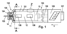
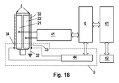
図1は、本発明による投与装置の一実施の形態の側面図を示している。図示の本発明による投与装置100は、液状の薬剤12が充填される容器1を有している。この実施の形態では、液状の薬剤12として、インシュリンが使用されているが、他の液状の薬剤12、例えば、ホルモン剤(例えば成長ホルモンなど)、バイオ薬剤又は生殖医療における治療手段の範囲内で用いる薬剤を、容器1に充填し、その後、同様の仕方でそれらの薬剤を投与することも可能である。
FIG. 1 shows a side view of an embodiment of the administration device according to the invention. The
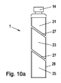
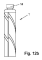
本発明による投与装置100は、鉛筆又はペンの形状を有しており、容器1内にある液体12を投与する際に、患者が楽に手に持つことができる。容器1は、カートリッジ又はアンプルの形態を有しており、本発明による投与装置100の端部領域102に配置されている。
The
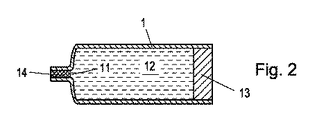
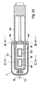
容器1は、図2に詳細に示されており、本発明による投与装置100の、この端部領域102にある一端において液体12を投与するための開口部11を有している。反対側の端において、容器1は、移動させることのできる態様で容器1内に装着されたプランジャ13を有している。このため、容器1は、開口部11の領域を除いて、一定の横断面を有する内部容積を有している。プランジャ13は、容器1内にある液体12が、容器1内にしっかりと封入され、開口部11を通じてのみ出ることができるように開口部11の反対側から、容器1を封止している。この代表的な実施の形態では、容器1の内部領域とプランジャ13は、円状の横断面を有し、実質的に円筒状の内部壁又は外部壁を備えている。プランジャ13を、容器1内に押し込む又は容器1内を前進させると、容器1内にある液体12は、開口部11を通って容器1から出ることができる。プランジャ13を、開口部11の方向に進めると、液体12は、開口部11を通って容器1から投与される。しかしながら、図2に示すように、容器1の開口部11は、使用前は、液体12が容器1から出ることがないよう、封止部材14によって封止されている。
The
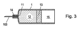
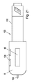
図3は、液体12の一部が、開口部11を通って注射針103を経由して投与された後の図2に示す容器1を示している。
FIG. 3 shows the
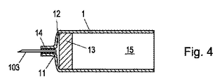
図4は、液体12が、開口部11を通り注射針103を経由して、容器1から全部出された後の図2に示す容器1を示している。図3及び図4の説明図において、プランジャ13は、中間位置及び最終位置のそれぞれにある、すなわち、容器1は、部分的に(図3)又は全体が(図4)空である。プランジャ13の後ろの領域15には、空気がある。さらに、本発明による投与装置100は、容器1の開口部11の領域に注射針103を有しており、前記注射針は、第1に、封止部材14を貫通して容器1内に突き出ており、第2に、投与装置1から突出している。
FIG. 4 shows the
図1に示すように、この代表的な実施の形態における注射針103は、本発明による投与装置100にねじ止めされたハウジング104に取り付けられている。本発明による投与装置100は、ハウジング104の鏡像反転の形態を有する適合する雌ねじに螺合する雄ねじ105を有している。図3に示すように、プランジャ13を、開口部11の方向に移動させると、容器1の内部にある液体を、開口部11及び注射針103を通じて、それぞれの患者に投与することができる。本発明による投与装置100のハウジングは、2個の覗き穴108を有することにより、容器1内にある残りの液体12の充填度Fを、視覚的に測定できるようにしているか、又は液体12において生じ得る濁り若しくは異物を認めることができるようにしている。
As shown in FIG. 1, the
さらに、本発明による投与装置100は、調節ユニット106を有しており(図1参照)、この調節ユニットにより、プランジャ13の或る一定の前進、それに対応して、或る一定量の投与する液体12を、予め設定することができる。投与する液体12の量を設定した後、推進要素109が、患者がアクチュエータユニット107に圧力をかけることにより、容器1のプランジャ13に押しつけられる。プランジャ13は、容器1内に押し込まれ、容器1内にある液体12は、注射針103を通って患者に投与される。推進要素109は、プランジャ13の進行方向Vに対する逆戻り、すなわち、開口部11から遠ざかって後戻りしないようにされているので、プランジャ13は、開口部11の方向にしかさらに動かすことができない。
Furthermore, the
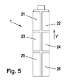
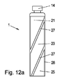
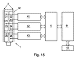
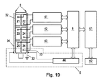
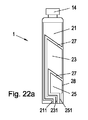
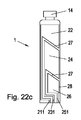
図5に示すような3対の測定電極を備えた容器1を用いるのが、特に好ましい。容器1は、図5に示すように、3対の測定電極21〜26を有している。全ての測定電極21〜26は、容器1の外側領域に配置されており、この場合には、容器1の外壁に配置されている。本発明の、この好適で代表的な実施の形態では、互いに割り当てられた2個の測定電極21〜26は、何れの場合にも、容器1の外壁上で互いに向かい合わせになっており、周方向に間隔を置いて設けられている。互いに割り当てられた測定電極21〜26の個々の対は、互いにプランジャ13の進行方向Vに間隔を置いて設けられている。第3の対の測定電極25、26は、容器1の開口部11から最も離れている。第1の対の測定電極21、22は、開口部11の最も近くにある。第2の測定電極対の測定電極23、24は、プランジャ13の進行方向Vに見て、第1の対の測定電極21、22と第3の対の測定電極25、26との間にある。測定電極21〜26は、容器1の外壁の領域で、広がっている。図5に示す代表的な実施の形態では、測定電極21〜26は、長方形の形状を有している。測定電極21〜26は、プランジャ13の進行の全範囲にわたって延びている。複数の測定電極対を用いる場合、一つの測定電極対のプランジャ13の進行方向Vにおける拡がりが、プランジャの進行方向Vにおけるプランジャ13の拡がりに適合するのが好ましい。
It is particularly preferable to use a
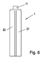
しかしながら、代わりに、他の電極形状、例えば円状又は櫛状の電極形状を測定電極21〜26に用いてもよい。複数対の測定電極対21〜26の使用は、細長い容器1の場合には、液体量すなわち液体充填度の正確な測定を行う観点では、原則として好ましいが、特に短い又は小さい容器1の場合には、必須ではない。図6に示す容器1の別の代表的な実施の形態では、細長く、プランジャが進行する全範囲にわたって延びる具体的な構成を有する1対の測定電極21、22だけが備わっている。2個の測定電極21、22は、プランジャ13の進行方向Vの観点において同じ高さすなわち同じ位置で、周側面上で互いに向かい合っている。
However, instead, other electrode shapes, such as circular or comb-like electrode shapes, may be used for the
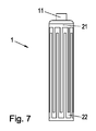
さらに、別の形状の測定電極21〜26を用いることもできる。好ましい一実施の形態では、測定電極21〜26は、櫛形電極、すなわちすだれ状電極として構成されている。これらの測定電極は21〜26は、対になって互いに割り当てられており、測定電極21、22;23、24;25、26の歯が互いに入り込むように割り当てられた櫛形構造を有している。図7及び図8に示すように、櫛形電極は、一対の測定電極を有する構成(図7)にも、数対の測定電極21、22;23、24;25、26を有する構成にも、どちらにも使用することができる。
Furthermore,
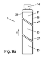
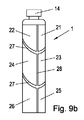
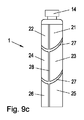
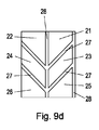
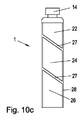
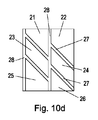
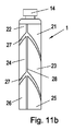
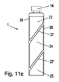
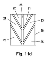
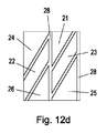
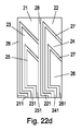
用途に応じて、いろいろな寸法を有する測定電極21〜26を備えて、容器1内の充填度Fの特に好ましい測定を容易にすることもできる。平行四辺形又は三角形の測定電極21〜26の使用は特に好ましく、平行四辺形又は三角形の測定電極は、特に好ましくは、プランジャの進行方向V、すなわち容器1の長手方向の軸線に対して角度をなして、例えば45°の角度をなして延びる分離領域27によって、互いに隔てられている。こうした構成の場合には、滑らかな推移が生じるので、特に正確な充填度Fの測定が可能になる。図9a〜図12dは、平行四辺形又は三角形の測定電極21〜26の間の進行方向Vに対して角度をなす分離領域27を有する四つの異なる実施の形態を示している。さらに、これらの実施の形態では、何れの場合にも、互いに割り当てられた対の測定電極21、22;23、24;25、26を互いに隔てる容器の長手方向の軸線と平行な分離領域28が設けられている。
Depending on the application, the
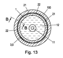
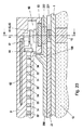
全てのこれらの測定電極構成に関して、測定電極21〜26の間の静電容量によって、容器1の充填度Fを推断することができる。本発明は、投与装置において、測定電極21〜26の外側の電場に対する電気遮蔽部材3を、容器1の周囲に鞘のような態様で配置することにより、できる限り正確な、個々の静電容量C1、C2、C3の測定を促進し、したがって、容器1の充填度に関する推断を引き出すことができる。図13は、容器1の断面図を示しており、この断面図は、電気遮蔽部材3、測定電極21、22、容器の壁及び容器1内部の液体12を示している。電気遮蔽部材3は、人が本発明による投与装置100に触れて又は本発明による投与装置100に接近して、その結果、測定電極21、22に広がる電場の状態を変えても、測定電極21、22間で測定される静電容量が、歪曲されない又は無視できる程度にしか歪曲されないようにしている。本発明の第1の代表的な実施の形態では、電気遮蔽部材3は、導電性材料からなるフィルム、例えば、50μmの厚さを有する銅のフィルムとして形成され、この導電性材料からなるフィルムは、容器1と容器に接する測定電極21、22の周囲に、鞘のような態様で巻き付けられている。測定電極21、22と電気遮蔽部材3は、互いに隔てられており、電気的に導通する態様で互いに接続されてはいない。電気遮蔽部材3は、外部作用、例えば、測定電極21、22のすぐ外側の領域における誘電率と電場の変化の影響を抑制する働きをする。電気遮蔽部材3は、測定電極21、22と容器1の両方を取り囲んでおり、測定電極と容器1との間に位置していないのが好ましい。特に、電気遮蔽部材3と測定電極との間に半径方向の間隔があるのが好ましいことが分かっている。さらに、電気遮蔽部材3を、全体が導電性のフィルムとして形成する必要はなく、代わりに、非導電性の支持体、例えば非導電性のフィルムなどに配置された個々の導体トラックの形態に具現化してもよい。
For all these measurement electrode configurations, the filling degree F of the
図13aは、図1の細部Zを、図13の線B−Bに沿う断面図で示している。測定電極21、23、25と電気遮蔽部材3に対する容器1の壁の配置を、正確な尺度ではないが、明示することができる。フィルム3に付した個々の導体32〜34が、断面で示されている。本発明による投与装置100のハウジングが、電気遮蔽部材3の外側に位置している。
FIG. 13a shows the detail Z of FIG. 1 in a sectional view along the line BB of FIG. The arrangement of the walls of the
そのほか、電気遮蔽部材3を、本発明による投与装置100の外壁のすぐ外側に及び/又は少なくとも部分的に容器1を包囲する支持体31の外側に配置してもよい。この場合には、支持体31は、同時に、電気遮蔽部材3と測定電極21、22との間に半径方向の間隔をもたらす役割をする。
In addition, the
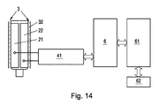
容器1内の液体12の現在の充填度Fを測定するのに、先ず、測定電極21、22間の現在の静電容量が測定される。図14は、1対の測定電極21、22の静電容量を測定する測定装置を示している。図15は、複数対の測定電極21〜26用いた測定装置を示している。図14及び図15では、それぞれ1個又は3個の静電容量測定装置41、42、43が上流に配置された、マイクロコントローラの形態をしたコンピュータユニット6が、備わっている。図15に示す静電容量測定装置41、42、43の各々は、測定電極21〜26の各対に割り当てられている。測定電極21〜26は、それぞれ、静電容量測定装置41、42、43の接続部に接続されている。それぞれの測定電極対のそれぞれの静電容量に対応した、その静電容量を表す又はその静電容量に比例する静電容量測定値C1、C2、C3の各々は、静電容量測定装置41、42、43の出力において得ることができ、前記静電容量測定値は、コンピュータユニット6に送られる。以下に説明する較正プロセスに基づき、コンピュータユニット6は、送られた個々の静電容量測定値C1、C2、C3に基づいて充填度Fの値を決定する。コンピュータユニット6は、この値を、その出力において利用可能に維持する。特に、求められ次第、この値は、コンピュータユニット6に下流に配置されたアンテナ62を経て、外部のデータ通信装置(図示せず)に送ることができる。
In order to measure the current filling degree F of the liquid 12 in the
もちろん、使用する測定電極21〜26の対の数は、測定の精度に対する要求に適合させてよい。1対の測定電極21、22を用い、これらの測定電極21、22の間で測定された静電容量測定値C1のみを用いて、充填度Fを測定することもできる(図15)。
Of course, the number of pairs of measuring
アンテナ62に接続された通信制御装置61が、コンピュータユニット6の下流に配置されている。通信制御装置61は、測定された充填度Fを、外部のデータ通信装置に送るのを円滑にする。充填度に関するデータを外部のデータ通信装置に無線で送る代わりに、先行技術に開示された有線を用いて、例えば、ユニバーサル・シリアル・バス(USB)で、送ることも、もちろん可能である。さらに、外部のデータ通信装置が、電気エネルギーを、アンテナ62を経由して通信制御装置61,コンピュータユニット6、及び静電容量測定装置41〜43に送るようにして、図14及び図15に示す回路全体が、別個の電源なしで済ませるようにしてもよい。
A
以下に、容器1内の液体12の充填度Fの具体的な測定の仕方を、決定した静電容量測定値C1、C2、C3に基づいて詳細に説明する。図17は、個々の静電容量測定値C1、C2、C3が、図5に示す、本発明による容器1の実施の形態における充填度Fに依存する様子を、概略的に示している。容器1からの排出過程の始まりでは、初めのうちは液体12だけが測定電極21〜26の間にある。排出中、プランジャ13は最初に、第1の測定電極対の測定電極21、22の間の中間領域に達するので、液体12に対してプランジャ13の誘電率が低いため、第1の測定電極対の静電容量測定値C1の連続的な低下が認められる。プランジャ13が押されて、第1の測定電極対の測定電極21、22の間の中間領域を通過した後は、第1の測定電極対の2個の測定電極21、22の間には空気15がある。第1の測定電極対の2個の測定電極21、22の間にある空気の誘電率がさらに低いので、これらの測定電極21、22の間で測定される静電容量測定値C1は、さらに低下する。同様の挙動が、容器1を空にする際に、第2及び第3の測定電極対の測定電極23〜26の間の静電容量測定値C2、C3についても認められる。
Hereinafter, a specific method of measuring the filling degree F of the liquid 12 in the
本発明の特に好ましい実施の形態では、個々の静電容量測定値C1、C2、C3の合計Csumを用いて充填度Fを決定してもよい。較正曲線を決定することにより、複数の異なる充填度に関して、何れの場合にも、関連する個々の静電容量測定値C1、C2、C3の合計Csumを決定することができ、その際、一つの合計Csumが、それぞれ、一つの充填度Fに割り当てられる。そのようにして作成された個々のデータ記録は、各々静電容量測定値Csumと充填度Fを含んでおり、コンピュータユニット6内の較正メモリに保存される。
In a particularly preferred embodiment of the invention, the degree of filling F may be determined using the sum C sum of the individual capacitance measurements C 1 , C 2 , C 3 . By determining the calibration curve, the total C sum of the associated individual capacitance measurements C 1 , C 2 , C 3 can be determined in any case for a plurality of different filling degrees, In this case, one total C sum is assigned to one filling degree F. The individual data records thus created each contain a capacitance measurement C sum and a filling factor F and are stored in a calibration memory in the
そのほか、各々静電容量測定値Csumと充填度Fを含んだ個々の較正データ記録を、本発明による投与装置の外側の、例えば外部データ通信装置において、以後の充填度の測定用に、利用できるように保持してもよい。 In addition, individual calibration data records, each containing a capacitance measurement C sum and a filling degree F, are used for subsequent filling degree measurements, for example in an external data communication device, outside the dosing device according to the invention. You may hold it as you can.
個々の静電容量測定値C1、C2、C3を測定し、決定した後、それらの合計Csumが決定され、較正メモリに保存された個々の合計Csumと比較される。関連する合計Csumが、決定された静電容量測定値C1、C2、C3の合計と、最も合致する電極対が選択される。最も合致する合計Csumに割り当てられた充填度が、何れの場合にも、容器1の充填度Fと考えられ、コンピュータユニット6は、この充填度Fをその出力において利用可能に維持し、この充填度Fを、上述のように求められ次第、又はこうした求めなしに自主的に、アンテナ62を経由して外部のデータ通信装置に出力する。
After measuring and determining the individual capacitance measurements C 1 , C 2 , C 3 , their sum C sum is determined and compared with the individual sum C sum stored in the calibration memory. The electrode pair that best matches the associated sum C sum with the sum of the determined capacitance measurements C 1 , C 2 , C 3 is selected. The filling degree assigned to the best matching total C sum is in each case considered the filling degree F of the
実験によると、測定電極21〜26の間の複合した容量結合現象に明らかに起因して、充填度Fに応じて測定された静電容量C1、C2、C3の推移曲線が大幅にずれており、この推移曲線は、図17に示す理論的に予想される推移曲線から明らかにずれている。しかしながら、この測定できる推移曲線のプロファイルは、非常に良く再現することができ、各静電容量C1、C2、C3に関して、異なる推移曲線の部分又は充填度の範囲において異なる勾配を示し、理論的な予想に反して、推移曲線プロファイルの最大の勾配又は静電容量における最大の変動は、必ずしも、間に液面が測定時にある、それらの測定電極21〜26の間で生じるわけではない。しかし、推移曲線の勾配が大きいほど、測定の解答/精度が良いので、充填度を計算するのに、3個の個々の静電容量測定値の単純な合計を求める代わりに、加重した合計を用いてもよく、較正中、推移曲線の各部分における3個の加数各々に対し、専用の加重値が別々に決定される。
According to the experiment, the transition curves of the capacitances C 1 , C 2 , and C 3 measured according to the filling degree F are significantly increased due to the combined capacitive coupling phenomenon between the
薬剤を充填した容器1又は同じ構成の参照容器を空にする較正を行い、個々の静電容量C1、C2、C3と充填度Fとの間の換算を得る。空にする間、充填度F及び個々の静電容量C1、C2、C3が、それぞれ、決定される。空にする間に達した各充填度Fに関して、個々の静電容量値C1、C2、C3が、それぞれ求められる。この代表的な実施の形態では、容器を空にする間に、30個の等間隔の充填度Fに達し、初期状態が1で示され、全体が空になった状態が0で示される。静電容量測定値C1、C2、C3は各々、それぞれの充填度Fとそれぞれの加重値a、b、cに割り当てられた基準ベクトルVrefに保存される。したがって、基準ベクトルVrefは、各充填度Fに関して求められる。加重値は、加重した合計a・C1+b・C2+c・C3が、充填度Fへの線形近似である最適化によって設定される。
Calibration is performed to empty the
測定により決定した静電容量測定値C1、C2、C3に基づいて、実際の充填度Fを決定しようとする場合には、較正中に得られた加重値に基づいて、この決定をすることができ、この場合、静電容量測定値C1、C2、C3が得られたのと同数の加重値を、各測定に利用することができる。先ず、決定又は測定された静電容量測定値C1、C2、C3に基づいて、この静電容量測定値C1、C2、C3を成分として有するベクトルVmess[C1、C2、C3]が、生成される。次いで、このベクトルVmessは、決定した基準ベクトルVrefと比較され、ベクトルVmessから最も距離の近い基準ベクトルが求められる。この代表的な実施の形態では、距離の尺度として、ユークリッド距離が用いられている。次いで、ベクトルVmessから次に最も近い距離をそれぞれ有する基準ベクトルVrefが、決定される。較正によって決定された基準ベクトルVrefに適用する際に、それぞれの割り当てられた充填度Fを、これらの基準ベクトルに送り返す補間機能、例えば、線形補間機能が決定される。静電容量測定値C1、C2、C3が、補完機能に用いられ、平均した充填度の値が得られる。 When the actual filling degree F is to be determined based on the capacitance measurement values C 1 , C 2 , C 3 determined by the measurement, this determination is made based on the weight value obtained during calibration. In this case, the same number of weights as the capacitance measurements C 1 , C 2 , C 3 were obtained can be used for each measurement. First, based on the determined or measured capacitance measurement values C 1 , C 2 , C 3 , a vector V mass [C 1 , C 3 having the capacitance measurement values C 1 , C 2 , C 3 as components is used. 2 , C 3 ] is generated. Next, this vector V mass is compared with the determined reference vector V ref, and the reference vector having the closest distance from the vector V mass is obtained. In this representative embodiment, the Euclidean distance is used as a distance scale. The reference vectors V ref each having the next closest distance from the vector V mess are then determined. When applied to the reference vectors V ref determined by calibration, an interpolation function, for example a linear interpolation function, is sent back to each assigned filling degree F to these reference vectors. The capacitance measurement values C 1 , C 2 , and C 3 are used for the complementary function, and an average filling degree value is obtained.
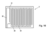
スペースの理由で、アンテナ62は、電気遮蔽部材3の外側に配置するのが好ましい。電気遮蔽部材3は、電気的及び磁気的に非伝導性の材料、例えば、プラスチックからなるフィルム31を有することにより、好ましい組み合わせを確保している。図16に示すように、フィルム31には、導体トラックの形態をした導体32〜34が設けられている。渦電流が生じ得る、大面積を持つ閉じた導体のループが形成されないようにフィルム31上に導体32〜34を形成すると、外部のデータ通信装置によって発される磁場が、電気遮蔽部材3のお蔭でそれほど影響されずに、アンテナ62によって受信されることができる。さらに、これにより、アンテナに接続された電機部品に十分にエネルギーを供給するのに十分な、電磁波の形態のエネルギーを、アンテナ62に送ることも可能になる。
For reasons of space, the
容器1内の充填度Fを測定する際にさらに精度が要求される場合には、例えば導電性の物体又は高い誘電体誘電率を有する物体の接触又は接近により、容器1の外部領域の電場が歪曲された時に、充填度Fの測定値を、無効にする又は充填度Fの測定値が、無効であるとみなすようにしてもよい。
If more accuracy is required when measuring the filling degree F in the
電気遮蔽部材3は、複数の導体32〜34が、コーティングによって形成された電気的及び磁気的に非伝導性のフィルム31を有している。この代表的な実施の形態では、フィルム31は、可撓性のプラスチックからなっている。導体トラックは、約50μmの層厚と約1000μmの幅を有している。導体32〜34の幅は、100〜3000μmの間であるのが好ましい。
The
導体32〜34の幅を3mm未満に限定し、渦電流が生じることにより、誘導結合に基づく通信、特に近距離無線通信に障害を生じさせるのを防止してもよい。さらに、導体32〜34を、図16に示すように、ループがない、すなわち、閉じた導体のループがない、すなわち、閉じたループを含まないように構成し、渦電流の発生を十分に防止して近距離無線通信の障害を回避するだけでなく、電気遮蔽部材3の内側にある測定電極21〜26に対する静電容量に関する影響を回避してもよい。
By limiting the width of the
したがって、本発明の、この代表的な一実施の形態では、3個の導体のうちの2個32、33が、互いに入り込む櫛形導体32、33として構成され、第3の導体34が、2個の櫛形導体32、33の間を、蛇行する態様で延びている。もちろん、この代表的な実施の形態の他に、フィルム31の表面上又はフィルムの内側の、或いは多層からなるフィルムの個々の層の間の、互いに電気的に接続されていない複数の導体トラック又は電極のループのない構成を有する複数の他の代表的な実施の形態もある。さらに、フィルム31の表側と裏側の両方に、導体32〜34を印刷してもよい。
Thus, in this exemplary embodiment of the present invention, two of the three
そのほか、複数の蛇行形状の導体34を、櫛形導体32、33の間に、互いに近接して並べて配置してもよく、複数の導体34を、フィルム31上に螺旋状に配置してもよい。
In addition, a plurality of meandering
2個の導体トラック、すなわち、2個の櫛形導体のうちの1個33と蛇行形状の導体34が、接触センサ5として用いられる。第2の櫛形導体32は、所定の接地電位にされ、電気遮蔽体としての役割をする。人が電気遮蔽部材3に接触する又は人が電気遮蔽部材3に接近すると、周囲の誘電率における変化の結果として、接触センサ5の導体33、34の間の静電容量が変化する。導体33、34の間のこの静電容量における変化は、さらに別の静電容量測定装置44によって測定してもよく、電気遮蔽部材3の導体33、34すなわち接触センサ5は、さらに別の静電容量測定装置44の測定接続部に接続されている。このさらに別の静電容量測定装置44は、さらに別の静電容量値C’を測定し、この静電容量値を、図18及び図19に示すように、コンピュータユニット6に送る。測定されたさらに別の静電容量測定値C’における変化が、所定の閾値Tを越えると、静電容量測定値C1、C2、C3に基づいて決定された充填度Fは、接触による誤りであるであるとみなされる。決定された充填度Fは、無効とされる。
Two conductor tracks, that is, one 33 of two comb conductors and a meandering
本発明の、この代表的な一実施の形態では、接触センサ5として作用すると同時に、櫛形導体32と蛇行形状の導体34からなる電気遮蔽部材3が、使用されている。しかしながら、物理的又は機能的見地から、電気遮蔽部材3と接触センサ5は、特に好ましい態様、すなわち、印刷することにより1つの平面に生産可能な態様で、図16に示す具体的な構成により実現することのできる2個の全く別個の異なるユニットである。もちろん、電気遮蔽部材3と接触センサ5のこの機能的分離は、容易に行うことができる。電気遮蔽部材3の又は接触センサ5の導体32、33、34は、フィルム31の同一の平面上にあり、単に説明の便宜上、図14、15、18及び19において、互いに近接して示されている。
In this representative embodiment of the present invention, the
本発明の別の実施の形態では、交換の際に、本発明による投与装置100から容器1を取り外すのが容易である。支持体(図示せず)が、容器1の外側で、容器1と電気遮蔽部材3との間に配置される。支持体には、測定電極21〜26が、配置される。支持体は、容器1に接しており、本発明による投与装置100のハウジングの一部分によって形成されるのが好ましい。測定電極21〜26は、容器1に接した支持体の壁に配置される。本発明による投与装置100のハウジングは、開けることができ、容器1を、本発明による投与装置100のハウジングから取り出すことができる。支持体は、本発明による投与装置100の一部分を構成している。
In another embodiment of the invention, it is easy to remove the
通信制御装置61、コンピュータユニット6、静電容量測定装置41〜44、及びアンテナ62は、フィルム31上に配置してもよく、好ましい。
The
本発明のさらに別の好ましい実施の形態が、図20に示されており、カバーキャップ9を有する投与装置を提示している。この実施の形態は、先に示した実施の形態と実質的に同等でおり、以下では、先の実施の形態との相違点だけを、より詳細に説明する。
Yet another preferred embodiment of the present invention is shown in FIG. 20 and presents a dispensing device having a
カバーキャップ9は、1個以上の掛止要素109によって、本発明による投与装置の支持体200に、着脱可能に取り付けられている。カバーキャップ9は、容器1と容器1に配置された測定電極21〜26を、鞘のように包囲している。先の実施の形態とは異なり、電気遮蔽部材3と接触センサ5は、カバーキャップ9の本体内に配置されている。カバーキャップ9が、支持体200に配置される限り、測定電極21〜26は、電気遮蔽部材3によって保護される。この実施の形態では、電気遮蔽部材3は、カバーキャップ9の本体に入れて成型されており、カバーキャップ9の本体によって全面的に包囲されている。この実施の形態においても同様に、電気遮蔽部材3は、カバーキャップ9によって全面的に包囲又は封入されたフィルム上に配置されている。この場合、電気遮蔽部材3は、注射針103と向かい合う、カバーキャップ9の端部領域においても、測定電極21〜26を包囲している。そのほか、フィルム及び/又は電気遮蔽部材3を、カバーキャップ9の外側に配置してもよい。
The
カバーキャップ9は、この端部領域に、注射針103の通路としての凹部99を有している。そのほか、注射針103は、カバーキャップ9のハウジングに、全体が包囲されていてもよい。
The
第2の代わりの実施の形態では、カバーキャップ9は、注射針103の端部において開いているスリーブの形態に構成されている。その結果、カバーキャップを着けたままでも、液体の注射又は投与が可能である。したがって、全体的に見て、カバーキャップは、注射針103又は容器1を全面的に覆う必要はない。
In a second alternative embodiment, the
カバーキャップ9が、覗き穴108の手前の位置に、さらなる覗き穴98を有することにより、本発明による投与装置の支持体200の覗き穴108を見るのが容易になる。
The
図21は、外側から見た本発明による投与装置100を示している。この概略図では、コンピュータユニット6(図23及び図25参照)に接続され、コンピュータユニットによって作動する表示ユニット90が見える。表示ユニット90の接続線が、カバーキャップ9内の電気遮蔽部材3の外側で延びている。
FIG. 21 shows the
図22a〜図22dは、測定電極21〜26が、取り得る構成を示している。個々の測定電極21〜26は、導電性の接続部によって接続接触部211、221、231、241、251、261に導かれる。これらの導電性の接続部は、測定電極21〜26及び接続接触部211、221、231、241、251、261と同様に、容器1の内側又は外側に、導体層として配置されるのが好ましい。
22a to 22d show configurations that the
原理的には、ここで、図9a〜図12dに示す全ての電極の形態を、それぞれの測定電極21〜26が、測定電極21〜26に割り当てられた容器1の外側領域で延びる導線によって、容器側の接続接触部211、221、231、241、251、261に導かれる状態で、使用することができる。図9a〜図9dに示すように、測定電極が2個だけ使用されている場合には、接続接触部211、221も2個だけである。
In principle, here all the electrode configurations shown in FIGS. 9a to 12d are made by means of conductors in which the
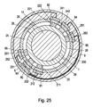
図23は、図20の線B−Bに沿う断面図を示している。本発明による投与装置100の支持体200は、各接続接触部211、221、231、241、251、261に関して、それぞれ、スルー接触部212、222、232、242、252、262を有しており、スルー接触部は、支持体200の外面に通じており、外側からタップすることができ、電気的に接触することができるように配置される。
FIG. 23 shows a cross-sectional view along the line BB in FIG. The
図25からも分かるように、カバーキャップ9は、その支持体200に面する開放端の領域に、いくつかの接続接触部91、92、93、94、95、96を有しており、これらの接続接触部は、スルー接触部212、222、232、242、252、262に、電気的に導通する態様で接続することができる。掛止要素109は、各々のスルー接触部212、222、232、242、252、262が、それぞれカバーキャップ9の接続接触部91、92、93、94、95、96のうちの1個と接触する唯一の位置においてのみ、掛止が可能な構成を有することにより、組付けミスを防止するのがよい。接続接触部211、221、231、241、251、261及びスルー接触部212、222、232、242、252、262及びカバーキャップ9の接続接触部91、92、93、94、95、96は全て、導電性の材料、特に銅からなっている。
As can be seen from FIG. 25, the
各接続接触部91、92、93、94、95、96は、静電容量測定ユニット41、42、43の接続部に接続されているので、それぞれの静電容量測定ユニット41、42、43は何れも、互いに向かい合って配置された2個の測定電極21、22;23、24;25、26の間の静電容量を測定する。静電容量測定ユニット41、42、43は、コンピュータユニット6に接続されている。
Since each
図23に示すアンテナ62は、電気遮蔽部材3の外側の領域で、カバーキャップ9に接触して又はカバーキャップ内に配置されている。この代表的な実施の形態では、アンテナ62は、電気遮蔽部材3とともに、カバーキャップ9と一緒に成型されており、カバーキャップ9の本体によって全面的に包囲されている。アンテナ9は、電気遮蔽部材3のフィルムの外側に配置されたフィルムに、両方のフィルムがカバーキャップの本体によって全面的に包囲された状態で、配置されるのが好ましい。
The
アンテナ62は、コンピュータユニット6に接続された通信制御装置に接続されている。電気遮蔽部材3の3個の導体32、33、34のうちの2個が、コンピュータユニット6に接続されたさらに別の静電容量測定装置44に、電気的に導通する態様で接続されている。
The
静電容量測定装置41、42、43、さらに別の静電容量測定装置44、通信制御装置61及び、必要に応じて、さらに別体の電池(図示せず)は、カバーキャップ9の内側に配置された、好ましくはカバーキャップと一緒に成型された共通のハウジング60内に組み込まれている。
Capacitance measuring
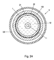
図24は、容器1の端部領域における、進行方向に対して直角な、線C−Cに沿う断面図を示している。この図では、カバーキャップ9内に配置された電気遮蔽部材3が、測定電極21〜26を取り囲んでいることが確認できる。この外は、図13を参照されたい。
FIG. 24 shows a cross-sectional view along the line CC, perpendicular to the direction of travel, in the end region of the
図26は、本発明によるさらに別の実施の形態を示しているが、この実施の形態では、電気遮蔽部材3がない。しかしながら、測定電極21〜26に10mmよりも近くに接近するのを防止する拡大されたカバーキャップ9が、正確な測定を確保している。この実施の形態では、電気遮蔽部材がないので、さらに別の静電容量測定装置は、設けられていない。
FIG. 26 shows still another embodiment according to the present invention, but in this embodiment, the
Claims (35)
容器(1)の外側領域に、特に容器の壁に接して、互いに向かい合って配置された少なくとも1対の容量性の測定電極(21、22)であって、測定電極の間の中間領域に位置するそれぞれの媒体の誘電率を測定する測定電極とを、
備えた液体(12)、特に液状の薬剤を人に投与する投与装置。 A container (1) filled with a liquid (12), said container having at one end an opening (11) for administering the liquid (12);
At least one pair of capacitive measuring electrodes (21, 22) arranged opposite each other on the outer region of the container (1), in particular in contact with the wall of the container, located in the intermediate region between the measuring electrodes Measuring electrodes for measuring the dielectric constant of each medium,
An administration device for administering a provided liquid (12), particularly a liquid drug, to a person.
電気遮蔽部材(3)は、半径方向に、測定電極(21、22)から距離を置いていること、及び/又は
電気遮蔽部材(3)は、導体トラックの形態をした導体(32、33、34)が被覆されたフィルム(31)として構成され、このフィルムは、特に、容器(1)に巻き付けられている又は容器(1)を囲んで配置されていることを、
特徴とする請求項1〜5の何れか1に記載の投与装置。 The area between the liquid (12) and the measuring electrode (21, 22) is not provided with an electric shielding member (3) and / or the electric shielding member (3) is arranged in the radial direction in the measuring electrode. The electrical shielding member (3) is configured as a film (31) coated with a conductor (32, 33, 34) in the form of a conductor track; This film is in particular wrapped around the container (1) or arranged around the container (1),
The administration device according to any one of claims 1 to 5, characterized in that
対になって互いに割り当てられた測定電極(21、22;23、24;25、26)のうちの2個が、それぞれ、容器(1)の外側領域、特に容器(1)の外壁に配置された2個の互いに入り込む櫛形導体によって形成されていることを、
特徴とする請求項1〜17の何れか1に記載の投与装置。 The measuring electrodes (21, 22; 23, 24; 25, 26) are arranged in a broad manner on the outer surface of the container (1), in particular having a rectangular, triangular, trapezoidal or parallelogram shape; And / or two of the measuring electrodes (21, 22; 23, 24; 25, 26) assigned to each other in pairs are respectively connected to the outer region of the container (1), in particular the outer wall of the container (1). Is formed by two interdigitated conductors arranged in each other,
18. The administration device according to any one of claims 1 to 17, characterized in that
測定電極(21、22;23、24;25、26)が、容器(1)に接する支持体の壁に配置され、特に投与装置(100)のハウジングの一部分が、支持体として形成されているか、又は支持体がハウジングに連結されていることを、
特徴とする請求項1〜18の何れか1に記載の投与装置。 On the outside of the container (1), a support in which measurement electrodes (21, 22; 23, 24; 25, 26) are arranged is arranged between the container (1) and the electric shielding member (3), and is supported. The body is preferably in contact with the container (1) and / or the measuring electrodes (21, 22; 23, 24; 25, 26) are arranged on the wall of the support in contact with the container (1), in particular A portion of the housing of the dosing device (100) is formed as a support or the support is connected to the housing;
19. The administration device according to any one of claims 1 to 18, characterized in that
カバーキャップ(9)が、容器(1)及び、特に、液体(12)に接触している注射針(103)を包囲しているか、
カバーキャップ(9)が、容器(1)及び/若しくは容器(1)に隣接するハウジングの一部(109)に、特に1回以上着脱可能な態様で、連結可能であるか、並びに/又は
カバーキャップ(9)が、注射針(103)の端部において開いているスリーブの形態に構成されていることを、 The cover cap (9) has a through recess (99) for dispensing liquid through the cover cap (9) in the region of the opening (11) of the container (1). 12) the needle (103) in contact with is guided through the recess,
The cover cap (9) surrounds the container (1) and in particular the injection needle (103) in contact with the liquid (12);
The cover cap (9) is connectable to the container (1) and / or part of the housing (109) adjacent to the container (1), in particular in a manner that it can be attached and detached once or more, and / or the cover The cap (9) is configured in the form of a sleeve that is open at the end of the needle (103),
カバーキャップ(9)の外側領域に表示ユニット(90)が備えられ、前記表示ユニットは、特に、容器内の液体の充填度を示すことを、
特徴とする請求項1〜23の何れか1に記載の投与装置。 The support (200) is provided with a peephole (108), and the liquid (12) can be visually observed through the peephole (108). If necessary, the cover cap (9) is attached to the peephole (108). ) In the region of), the liquid (12) can be seen through the sight hole (98) and / or the display unit (90) is located in the outer region of the cover cap (9). Provided that the display unit indicates in particular the degree of filling of the liquid in the container,
24. The administration device according to any one of claims 1 to 23, characterized in that
カバーキャップ、特にカバーキャップの内側に配置された、測定電極(21、22;23、24;25、26)に電気的に接触する接続接触部(91、92、93、94、95、96)と、
接続接触部(91、92、93、94、95、96)に接続された少なくとも1個の静電容量測定装置(41、42、43)とを、
備えているカバーキャップ。 A cover cap having a plurality of measuring electrodes (21, 22; 23, 24; 25, 26) and covering and covering the container (1) filled with liquid,
Connection contacts (91, 92, 93, 94, 95, 96) that are in electrical contact with the measuring electrodes (21, 22; 23, 24; 25, 26) arranged inside the cover cap, in particular the cover cap When,
At least one capacitance measuring device (41, 42, 43) connected to the connecting contact (91, 92, 93, 94, 95, 96);
Cover cap provided.
必要に応じ、コンピュータユニット(6)の下流に配置された、特に接続されたアンテナ(62)を有する通信制御装置(61)を、
特徴とする請求項25又は26に記載のカバーキャップ。 One or more capacitance measuring devices and / or a computer unit (6) arranged downstream of another capacitance measuring device;
If necessary, a communication control device (61) having a particularly connected antenna (62) arranged downstream of the computer unit (6),
27. A cover cap according to claim 25 or 26, wherein
カバーキャップ(9)が、スリーブの形態に構成されていることを、
特徴とする請求項25〜28の何れか1に記載のカバーキャップ。 In particular, a penetrating recess (99) arranged in the region of the opening (11) of the container (1) is provided, and liquid administration through the cover cap (9) and / or the cover cap (9) Is configured in the form of a sleeve,
The cover cap according to any one of claims 25 to 28.
特に、容器の内部の液体(12)の充填度を示す表示ユニット(90)が、カバーキャップ(9)の外側領域に設けられることを、
特徴とする請求項23〜30の何れか1に記載のカバーキャップ。 A viewing hole (98) that allows the liquid inside the cover cap and container (1) to be seen through the outside,
In particular, the display unit (90) indicating the degree of filling of the liquid (12) inside the container is provided in the outer region of the cover cap (9),
The cover cap according to any one of claims 23 to 30, wherein the cover cap is any one of claims 23 to 30.
特に外側電気遮蔽部材(3)を備えた容器(1)の外側領域に互いに向かい合って配置された少なくとも1対の測定電極(21、22)が、静電容量測定用に設けられており、
2個の測定電極(21、22)間の静電容量(C1)が測定され、測定された静電容量(C1)に基づいて、所定の較正機能に従い充填度値(F)が決定される方法であって、
測定電極(21、22)の外側領域で、電気遮蔽部材(3)の領域に、特に電気遮蔽部材(3)に配置された導体(33、34)を用いて、さらに別の静電容量(C’)を測定すること、
さらに別の静電容量(C’)を、閾値(T)と比較すること、及び
さらに別の静電容量(C’)が、閾値(T)よりも低い場合にのみ、充填度値(F)を有効であるとみなすことを、
特徴とする方法。 Especially in the method of measuring and confirming the filling degree (F) in the container (1) arranged in the administration device (100) according to any one of claims 1 to 24,
In particular, at least one pair of measuring electrodes (21, 22) arranged opposite each other in the outer region of the container (1) with the outer electrical shielding member (3) is provided for capacitance measurement,
The capacitance (C 1 ) between the two measurement electrodes (21, 22) is measured, and the filling degree value (F) is determined according to a predetermined calibration function based on the measured capacitance (C 1 ). A method to be
Using the conductors (33, 34) arranged in the region of the electric shielding member (3), in particular in the region of the electric shielding member (3), in the outer region of the measuring electrodes (21, 22), another electrostatic capacity ( Measuring C ′),
Comparing yet another capacitance (C ′) with a threshold value (T) and only when the further capacitance (C ′) is lower than the threshold value (T), the filling degree value (F ) Is considered valid,
Feature method.
b)それぞれの充填度(F)を、これらの基準ベクトルの一つに各々割り当て、
c)個々の測定した静電容量(C1、C2、C3)を有するベクトル(Vmess)を決定し、
d)ベクトル(Vmess)からの距離、特にユークリッド距離が最も小さい複数の基準ベクトル(Vref)を探し求め、
e)工程b)で見出した基準ベクトル(Vref)に適用されたとき、これらの基準ベクトル(Vref)に割り当てられたそれぞれの充填度(F)をもたらす補間機能を形成し、
f)補間機能を、ベクトル(Vmess)に適用し、結果を充填度として用いる
ことを特徴とする請求項34に記載の方法。 a) Reference vectors (V ref ) each including a capacitance (C 1 , C 2 , C 3 ) between each pair of measurement electrodes (21 to 26) as components, for each of a plurality of filling degrees (F) Give,
b) assigning each degree of filling (F) to one of these reference vectors,
c) determining a vector (V mess ) having individual measured capacitances (C 1 , C 2 , C 3 );
d) Search for a plurality of reference vectors (V ref ) having the smallest distance from the vector (V mess ), particularly the Euclidean distance,
e) forming an interpolation function that, when applied to the reference vectors (V ref ) found in step b), results in the respective degree of filling (F) assigned to these reference vectors (V ref );
The method of claim 34, wherein f) an interpolation function is applied to the vector ( Vmess ) and the result is used as the degree of filling.
Applications Claiming Priority (5)
| Application Number | Priority Date | Filing Date | Title |
|---|---|---|---|
| AT502832014 | 2014-04-15 | ||
| ATA50283/2014 | 2014-04-15 | ||
| ATA50477/2014 | 2014-07-09 | ||
| ATA50477/2014A AT515762B1 (en) | 2014-04-15 | 2014-07-09 | Dispensing device for dispensing liquids |
| PCT/AT2015/050061 WO2015157785A1 (en) | 2014-04-15 | 2015-03-09 | Medication injector with capacitive fill level measurement capacity, and contact sensor |
Publications (2)
| Publication Number | Publication Date |
|---|---|
| JP2017511209A true JP2017511209A (en) | 2017-04-20 |
| JP2017511209A5 JP2017511209A5 (en) | 2018-02-08 |
Family
ID=52874874
Family Applications (1)
| Application Number | Title | Priority Date | Filing Date |
|---|---|---|---|
| JP2016562785A Pending JP2017511209A (en) | 2014-04-15 | 2015-03-09 | Drug syringe and contact sensor having capacity measurement based on capacitance |
Country Status (9)
| Country | Link |
|---|---|
| US (1) | US10369287B2 (en) |
| EP (1) | EP3131605B1 (en) |
| JP (1) | JP2017511209A (en) |
| CN (1) | CN106573110A (en) |
| AT (1) | AT515762B1 (en) |
| BR (1) | BR112016023670A2 (en) |
| DK (1) | DK3131605T3 (en) |
| ES (1) | ES2687034T3 (en) |
| WO (1) | WO2015157785A1 (en) |
Cited By (3)
| Publication number | Priority date | Publication date | Assignee | Title |
|---|---|---|---|---|
| JP2020521547A (en) * | 2017-05-25 | 2020-07-27 | ウエスト ファーマスーティカル サービシーズ インコーポレイテッド | Computer Controlled Syringe Utilizing Near Field Communication and Capacitance Detection |
| JP2021513646A (en) * | 2018-02-06 | 2021-05-27 | パッケージング テクノロジーズ アンド インスペクション、エルエルシイ | Devices and methods for testing and testing the integrity of self-injectors |
| KR102301284B1 (en) * | 2021-08-09 | 2021-09-13 | 주식회사 오디텍 | Level gauge sensor structure of fuel storage device |
Families Citing this family (20)
| Publication number | Priority date | Publication date | Assignee | Title |
|---|---|---|---|---|
| US10617805B2 (en) * | 2014-03-20 | 2020-04-14 | Exploramed Nc7, Inc. | Fluid measuring reservoir for breast pumps |
| CN107847677B (en) | 2015-07-31 | 2021-01-29 | 赛诺菲-安万特德国有限公司 | Sensor, cartridge and drug delivery device |
| US11020529B2 (en) * | 2015-07-31 | 2021-06-01 | Sanofi-Aventis Deutschland Gmbh | Sensor for a drug delivery device |
| WO2017021227A1 (en) * | 2015-07-31 | 2017-02-09 | Sanofi-Aventis Deutschland Gmbh | Sensor, cartridge and drug delivery device |
| WO2017021229A1 (en) | 2015-07-31 | 2017-02-09 | Sanofi-Aventis Deutschland Gmbh | Sensor, cartridge and drug delivery device |
| DE102015223868B4 (en) * | 2015-12-01 | 2024-02-22 | Ifm Electronic Gmbh | Arrangement and method for capacitive level determination |
| AT518695B1 (en) * | 2016-05-20 | 2018-08-15 | Ait Austrian Inst Tech Gmbh | Arrangement for determining the level of the liquid in the carpule |
| GB2554923B (en) * | 2016-10-14 | 2021-09-15 | Domino Uk Ltd | Improvements in or relating to inkjet printers |
| DE102016123489A1 (en) * | 2016-12-05 | 2018-06-07 | Prominent Gmbh | level sensor |
| WO2018226782A1 (en) * | 2017-06-06 | 2018-12-13 | West Pharmaceutical Services, Inc. | Elastomer articles having embedded electronics and methods of manufacturing the same |
| CN116115845A (en) | 2017-06-24 | 2023-05-16 | 纳科斯达格医药股份有限公司 | Fluid management and measurement system, apparatus and method |
| US10548688B2 (en) | 2017-07-10 | 2020-02-04 | Addent, Inc. | Device and method for heating dental composite materials |
| US10172690B1 (en) * | 2017-07-10 | 2019-01-08 | Addent, Inc. | Device and method for heating dental composite materials |
| CN109839169A (en) * | 2017-11-27 | 2019-06-04 | 北京至感传感器技术研究院有限公司 | Capacitance level transducer and vacuum degree on-Line Monitor Device |
| US10151616B1 (en) * | 2017-11-28 | 2018-12-11 | Semiconductor Components Industries, Llc | Flowable material level sensing with shaped electrodes |
| EP3501568A1 (en) * | 2017-12-20 | 2019-06-26 | Valtronic Technologies (Holding) SA | Portable liquid injection device |
| WO2019162222A1 (en) * | 2018-02-26 | 2019-08-29 | Haselmeier Ag | Dosage determination using electrical conductivity in an injection device |
| USD943737S1 (en) * | 2019-01-22 | 2022-02-15 | Certa Dose, Inc. | Overdose resistant drug delivery syringe |
| CN111135387B (en) * | 2020-02-27 | 2021-11-02 | 徐勇 | Dripping speed monitoring device and method based on multi-sensor fusion |
| CN113155234A (en) * | 2021-04-25 | 2021-07-23 | 上海钛米机器人股份有限公司 | Liquid level detection system, method, device, computer device and readable storage medium |
Citations (4)
| Publication number | Priority date | Publication date | Assignee | Title |
|---|---|---|---|---|
| JP2008516709A (en) * | 2004-10-21 | 2008-05-22 | ノボ・ノルデイスク・エー/エス | Drug delivery system with detector of signal indicative of released dosage |
| JP2011078751A (en) * | 2009-09-18 | 2011-04-21 | Becton Dickinson & Co | Hub assembly having hidden needle for drug delivery pen |
| WO2013012526A1 (en) * | 2011-07-18 | 2013-01-24 | Mallinckrodt Llc | Injection system with capacitive sensing |
| WO2014052997A1 (en) * | 2012-10-05 | 2014-04-10 | Seibersdorf Labor Gmbh | Dispensing device for medications |
Family Cites Families (10)
| Publication number | Priority date | Publication date | Assignee | Title |
|---|---|---|---|---|
| US6110148A (en) * | 1994-07-22 | 2000-08-29 | Health Hero Network, Inc. | Capacitance-based dose measurements in syringes |
| US6490920B1 (en) * | 1997-08-25 | 2002-12-10 | Millennium Sensors Ltd. | Compensated capacitive liquid level sensor |
| CA2772050C (en) * | 2002-12-26 | 2016-09-06 | Meso Scale Technologies, Llc. | Assay cartridges and methods of using the same |
| DE102004040441A1 (en) | 2004-08-20 | 2006-06-14 | Disetronic Licensing Ag | Apparatus and method for determining the level of an ampoule |
| JP5225974B2 (en) | 2006-03-20 | 2013-07-03 | ノボ・ノルデイスク・エー/エス | Measurement of cartridge contents by capacitive means |
| US20080152507A1 (en) * | 2006-12-21 | 2008-06-26 | Lifescan, Inc. | Infusion pump with a capacitive displacement position sensor |
| FR2937723B1 (en) * | 2008-10-27 | 2018-12-07 | Sensile Medical Ag | CARTRIDGE WITH FILLING LEVEL DETECTION |
| US8556865B2 (en) * | 2009-02-27 | 2013-10-15 | Lifescan, Inc. | Medical module for drug delivery pen |
| AT512504B1 (en) * | 2012-03-22 | 2013-09-15 | Seibersdorf Labor Gmbh | Apparatus and method for determining the capacity |
| US20140074062A1 (en) * | 2012-08-06 | 2014-03-13 | Sean Caffey | Piston pump devices |
-
2014
- 2014-07-09 AT ATA50477/2014A patent/AT515762B1/en not_active IP Right Cessation
-
2015
- 2015-03-09 ES ES15716393.2T patent/ES2687034T3/en active Active
- 2015-03-09 WO PCT/AT2015/050061 patent/WO2015157785A1/en active Application Filing
- 2015-03-09 JP JP2016562785A patent/JP2017511209A/en active Pending
- 2015-03-09 BR BR112016023670A patent/BR112016023670A2/en not_active IP Right Cessation
- 2015-03-09 DK DK15716393.2T patent/DK3131605T3/en active
- 2015-03-09 EP EP15716393.2A patent/EP3131605B1/en active Active
- 2015-03-09 CN CN201580029147.6A patent/CN106573110A/en active Pending
- 2015-03-09 US US15/302,044 patent/US10369287B2/en not_active Expired - Fee Related
Patent Citations (4)
| Publication number | Priority date | Publication date | Assignee | Title |
|---|---|---|---|---|
| JP2008516709A (en) * | 2004-10-21 | 2008-05-22 | ノボ・ノルデイスク・エー/エス | Drug delivery system with detector of signal indicative of released dosage |
| JP2011078751A (en) * | 2009-09-18 | 2011-04-21 | Becton Dickinson & Co | Hub assembly having hidden needle for drug delivery pen |
| WO2013012526A1 (en) * | 2011-07-18 | 2013-01-24 | Mallinckrodt Llc | Injection system with capacitive sensing |
| WO2014052997A1 (en) * | 2012-10-05 | 2014-04-10 | Seibersdorf Labor Gmbh | Dispensing device for medications |
Cited By (4)
| Publication number | Priority date | Publication date | Assignee | Title |
|---|---|---|---|---|
| JP2020521547A (en) * | 2017-05-25 | 2020-07-27 | ウエスト ファーマスーティカル サービシーズ インコーポレイテッド | Computer Controlled Syringe Utilizing Near Field Communication and Capacitance Detection |
| JP2021513646A (en) * | 2018-02-06 | 2021-05-27 | パッケージング テクノロジーズ アンド インスペクション、エルエルシイ | Devices and methods for testing and testing the integrity of self-injectors |
| JP7348194B2 (en) | 2018-02-06 | 2023-09-20 | パッケージング テクノロジーズ アンド インスペクション、エルエルシイ | Devices and methods for testing and inspecting the integrity of autoinjectors |
| KR102301284B1 (en) * | 2021-08-09 | 2021-09-13 | 주식회사 오디텍 | Level gauge sensor structure of fuel storage device |
Also Published As
| Publication number | Publication date |
|---|---|
| EP3131605A1 (en) | 2017-02-22 |
| DK3131605T3 (en) | 2018-11-26 |
| BR112016023670A2 (en) | 2017-08-15 |
| US10369287B2 (en) | 2019-08-06 |
| US20170119970A1 (en) | 2017-05-04 |
| AT515762A1 (en) | 2015-11-15 |
| ES2687034T3 (en) | 2018-10-23 |
| EP3131605B1 (en) | 2018-08-01 |
| AT515762B1 (en) | 2016-02-15 |
| CN106573110A (en) | 2017-04-19 |
| WO2015157785A1 (en) | 2015-10-22 |
Similar Documents
| Publication | Publication Date | Title |
|---|---|---|
| JP2017511209A (en) | Drug syringe and contact sensor having capacity measurement based on capacitance | |
| JP6163209B2 (en) | Medicine dispenser device | |
| JP2017511209A5 (en) | ||
| JP6140267B2 (en) | Capacitive filling degree sensor based on short-range wireless communication for insulin pen | |
| JP6798989B2 (en) | A device for attaching to a portable liquid injection device | |
| JP2015512509A5 (en) | ||
| JP6719029B1 (en) | Plunger position detection and transmission using electromagnetic induction. | |
| JP6871428B2 (en) | Computer-controlled syringe using short-range wireless communication and capacitance detection | |
| CN206638722U (en) | A kind of anti-static device of dispensing machine | |
| CN207356069U (en) | Standard source bogey and thyroid function detection device | |
| US20230135876A1 (en) | Liquid storage assembly, electronic vaporization apparatus, and remaining volume detection method | |
| US20230042083A1 (en) | Drug delivery monitoring system | |
| US20230277779A1 (en) | Syringes and injectors with capacitive sensing and methods of making and using same | |
| US20230398290A1 (en) | Capacitive sensing for drug delivery | |
| AT518695B1 (en) | Arrangement for determining the level of the liquid in the carpule | |
| Virbalis et al. | Tooth canal working length electric meter |
Legal Events
| Date | Code | Title | Description |
|---|---|---|---|
| A621 | Written request for application examination |
Free format text: JAPANESE INTERMEDIATE CODE: A621 Effective date: 20171107 |
|
| A521 | Request for written amendment filed |
Free format text: JAPANESE INTERMEDIATE CODE: A523 Effective date: 20171221 |
|
| A977 | Report on retrieval |
Free format text: JAPANESE INTERMEDIATE CODE: A971007 Effective date: 20180928 |
|
| A131 | Notification of reasons for refusal |
Free format text: JAPANESE INTERMEDIATE CODE: A131 Effective date: 20181016 |
|
| A601 | Written request for extension of time |
Free format text: JAPANESE INTERMEDIATE CODE: A601 Effective date: 20190108 |
|
| A521 | Request for written amendment filed |
Free format text: JAPANESE INTERMEDIATE CODE: A523 Effective date: 20190312 |
|
| A02 | Decision of refusal |
Free format text: JAPANESE INTERMEDIATE CODE: A02 Effective date: 20190709 |