JP2017510218A - CSI feedback for multiple subframe sets - Google Patents
CSI feedback for multiple subframe sets Download PDFInfo
- Publication number
- JP2017510218A JP2017510218A JP2016562056A JP2016562056A JP2017510218A JP 2017510218 A JP2017510218 A JP 2017510218A JP 2016562056 A JP2016562056 A JP 2016562056A JP 2016562056 A JP2016562056 A JP 2016562056A JP 2017510218 A JP2017510218 A JP 2017510218A
- Authority
- JP
- Japan
- Prior art keywords
- subframe
- csi
- configuration
- imr
- uplink
- Prior art date
- Legal status (The legal status is an assumption and is not a legal conclusion. Google has not performed a legal analysis and makes no representation as to the accuracy of the status listed.)
- Pending
Links
- 238000000034 method Methods 0.000 claims abstract description 51
- 238000005259 measurement Methods 0.000 claims description 58
- 230000011664 signaling Effects 0.000 claims description 34
- 238000004891 communication Methods 0.000 claims description 24
- 230000008569 process Effects 0.000 claims description 15
- 238000012913 prioritisation Methods 0.000 claims description 12
- 230000008859 change Effects 0.000 claims description 7
- 230000000737 periodic effect Effects 0.000 claims description 7
- 239000000969 carrier Substances 0.000 claims description 5
- 238000001514 detection method Methods 0.000 claims description 5
- 230000004044 response Effects 0.000 claims 2
- 230000006978 adaptation Effects 0.000 abstract description 5
- 230000006870 function Effects 0.000 description 17
- 230000005540 biological transmission Effects 0.000 description 14
- 238000012545 processing Methods 0.000 description 14
- 238000005516 engineering process Methods 0.000 description 9
- 238000010586 diagram Methods 0.000 description 8
- 101150096310 SIB1 gene Proteins 0.000 description 4
- 230000006835 compression Effects 0.000 description 4
- 238000007906 compression Methods 0.000 description 4
- 125000004122 cyclic group Chemical group 0.000 description 4
- 238000007726 management method Methods 0.000 description 4
- 238000013459 approach Methods 0.000 description 3
- 230000001413 cellular effect Effects 0.000 description 3
- 238000013461 design Methods 0.000 description 3
- QHPJWPQRZMBKTG-UHFFFAOYSA-N ethyl 2-[2-methoxy-4-[(4-oxo-2-sulfanylidene-1,3-thiazolidin-5-ylidene)methyl]phenoxy]acetate Chemical compound C1=C(OC)C(OCC(=O)OCC)=CC=C1C=C1C(=O)NC(=S)S1 QHPJWPQRZMBKTG-UHFFFAOYSA-N 0.000 description 3
- 238000013468 resource allocation Methods 0.000 description 3
- 230000011218 segmentation Effects 0.000 description 3
- 238000001228 spectrum Methods 0.000 description 3
- 230000009286 beneficial effect Effects 0.000 description 2
- 238000010295 mobile communication Methods 0.000 description 2
- 230000003287 optical effect Effects 0.000 description 2
- 230000010363 phase shift Effects 0.000 description 2
- 101150001149 CSI1 gene Proteins 0.000 description 1
- 230000009471 action Effects 0.000 description 1
- 230000002776 aggregation Effects 0.000 description 1
- 238000004220 aggregation Methods 0.000 description 1
- 238000003491 array Methods 0.000 description 1
- 230000008901 benefit Effects 0.000 description 1
- 239000003795 chemical substances by application Substances 0.000 description 1
- 238000004590 computer program Methods 0.000 description 1
- 239000012141 concentrate Substances 0.000 description 1
- 238000012937 correction Methods 0.000 description 1
- 230000006837 decompression Effects 0.000 description 1
- 230000000977 initiatory effect Effects 0.000 description 1
- 230000007774 longterm Effects 0.000 description 1
- 238000013507 mapping Methods 0.000 description 1
- 238000012986 modification Methods 0.000 description 1
- 230000004048 modification Effects 0.000 description 1
- 230000008520 organization Effects 0.000 description 1
- 238000011084 recovery Methods 0.000 description 1
- 230000001360 synchronised effect Effects 0.000 description 1
Images


Classifications
-
- H—ELECTRICITY
- H04—ELECTRIC COMMUNICATION TECHNIQUE
- H04W—WIRELESS COMMUNICATION NETWORKS
- H04W72/00—Local resource management
- H04W72/20—Control channels or signalling for resource management
- H04W72/23—Control channels or signalling for resource management in the downlink direction of a wireless link, i.e. towards a terminal
-
- H—ELECTRICITY
- H04—ELECTRIC COMMUNICATION TECHNIQUE
- H04L—TRANSMISSION OF DIGITAL INFORMATION, e.g. TELEGRAPHIC COMMUNICATION
- H04L5/00—Arrangements affording multiple use of the transmission path
- H04L5/003—Arrangements for allocating sub-channels of the transmission path
- H04L5/0048—Allocation of pilot signals, i.e. of signals known to the receiver
-
- H—ELECTRICITY
- H04—ELECTRIC COMMUNICATION TECHNIQUE
- H04L—TRANSMISSION OF DIGITAL INFORMATION, e.g. TELEGRAPHIC COMMUNICATION
- H04L1/00—Arrangements for detecting or preventing errors in the information received
- H04L1/02—Arrangements for detecting or preventing errors in the information received by diversity reception
- H04L1/06—Arrangements for detecting or preventing errors in the information received by diversity reception using space diversity
- H04L1/0618—Space-time coding
- H04L1/0675—Space-time coding characterised by the signaling
- H04L1/0693—Partial feedback, e.g. partial channel state information [CSI]
-
- H—ELECTRICITY
- H04—ELECTRIC COMMUNICATION TECHNIQUE
- H04B—TRANSMISSION
- H04B17/00—Monitoring; Testing
- H04B17/30—Monitoring; Testing of propagation channels
- H04B17/309—Measuring or estimating channel quality parameters
- H04B17/345—Interference values
-
- H—ELECTRICITY
- H04—ELECTRIC COMMUNICATION TECHNIQUE
- H04B—TRANSMISSION
- H04B7/00—Radio transmission systems, i.e. using radiation field
- H04B7/02—Diversity systems; Multi-antenna system, i.e. transmission or reception using multiple antennas
- H04B7/04—Diversity systems; Multi-antenna system, i.e. transmission or reception using multiple antennas using two or more spaced independent antennas
- H04B7/0413—MIMO systems
-
- H—ELECTRICITY
- H04—ELECTRIC COMMUNICATION TECHNIQUE
- H04B—TRANSMISSION
- H04B7/00—Radio transmission systems, i.e. using radiation field
- H04B7/02—Diversity systems; Multi-antenna system, i.e. transmission or reception using multiple antennas
- H04B7/04—Diversity systems; Multi-antenna system, i.e. transmission or reception using multiple antennas using two or more spaced independent antennas
- H04B7/06—Diversity systems; Multi-antenna system, i.e. transmission or reception using multiple antennas using two or more spaced independent antennas at the transmitting station
- H04B7/0613—Diversity systems; Multi-antenna system, i.e. transmission or reception using multiple antennas using two or more spaced independent antennas at the transmitting station using simultaneous transmission
- H04B7/0615—Diversity systems; Multi-antenna system, i.e. transmission or reception using multiple antennas using two or more spaced independent antennas at the transmitting station using simultaneous transmission of weighted versions of same signal
- H04B7/0619—Diversity systems; Multi-antenna system, i.e. transmission or reception using multiple antennas using two or more spaced independent antennas at the transmitting station using simultaneous transmission of weighted versions of same signal using feedback from receiving side
- H04B7/0621—Feedback content
- H04B7/0626—Channel coefficients, e.g. channel state information [CSI]
-
- H—ELECTRICITY
- H04—ELECTRIC COMMUNICATION TECHNIQUE
- H04L—TRANSMISSION OF DIGITAL INFORMATION, e.g. TELEGRAPHIC COMMUNICATION
- H04L1/00—Arrangements for detecting or preventing errors in the information received
-
- H—ELECTRICITY
- H04—ELECTRIC COMMUNICATION TECHNIQUE
- H04L—TRANSMISSION OF DIGITAL INFORMATION, e.g. TELEGRAPHIC COMMUNICATION
- H04L5/00—Arrangements affording multiple use of the transmission path
- H04L5/0001—Arrangements for dividing the transmission path
- H04L5/0003—Two-dimensional division
- H04L5/0005—Time-frequency
- H04L5/0007—Time-frequency the frequencies being orthogonal, e.g. OFDM(A), DMT
- H04L5/001—Time-frequency the frequencies being orthogonal, e.g. OFDM(A), DMT the frequencies being arranged in component carriers
-
- H—ELECTRICITY
- H04—ELECTRIC COMMUNICATION TECHNIQUE
- H04L—TRANSMISSION OF DIGITAL INFORMATION, e.g. TELEGRAPHIC COMMUNICATION
- H04L5/00—Arrangements affording multiple use of the transmission path
- H04L5/0091—Signaling for the administration of the divided path
- H04L5/0092—Indication of how the channel is divided
-
- H—ELECTRICITY
- H04—ELECTRIC COMMUNICATION TECHNIQUE
- H04L—TRANSMISSION OF DIGITAL INFORMATION, e.g. TELEGRAPHIC COMMUNICATION
- H04L5/00—Arrangements affording multiple use of the transmission path
- H04L5/14—Two-way operation using the same type of signal, i.e. duplex
- H04L5/1469—Two-way operation using the same type of signal, i.e. duplex using time-sharing
-
- H—ELECTRICITY
- H04—ELECTRIC COMMUNICATION TECHNIQUE
- H04L—TRANSMISSION OF DIGITAL INFORMATION, e.g. TELEGRAPHIC COMMUNICATION
- H04L69/00—Network arrangements, protocols or services independent of the application payload and not provided for in the other groups of this subclass
- H04L69/22—Parsing or analysis of headers
-
- H—ELECTRICITY
- H04—ELECTRIC COMMUNICATION TECHNIQUE
- H04W—WIRELESS COMMUNICATION NETWORKS
- H04W12/00—Security arrangements; Authentication; Protecting privacy or anonymity
- H04W12/03—Protecting confidentiality, e.g. by encryption
- H04W12/033—Protecting confidentiality, e.g. by encryption of the user plane, e.g. user's traffic
-
- H—ELECTRICITY
- H04—ELECTRIC COMMUNICATION TECHNIQUE
- H04W—WIRELESS COMMUNICATION NETWORKS
- H04W24/00—Supervisory, monitoring or testing arrangements
-
- H—ELECTRICITY
- H04—ELECTRIC COMMUNICATION TECHNIQUE
- H04W—WIRELESS COMMUNICATION NETWORKS
- H04W24/00—Supervisory, monitoring or testing arrangements
- H04W24/10—Scheduling measurement reports ; Arrangements for measurement reports
-
- H—ELECTRICITY
- H04—ELECTRIC COMMUNICATION TECHNIQUE
- H04W—WIRELESS COMMUNICATION NETWORKS
- H04W48/00—Access restriction; Network selection; Access point selection
-
- H—ELECTRICITY
- H04—ELECTRIC COMMUNICATION TECHNIQUE
- H04W—WIRELESS COMMUNICATION NETWORKS
- H04W72/00—Local resource management
- H04W72/04—Wireless resource allocation
-
- H—ELECTRICITY
- H04—ELECTRIC COMMUNICATION TECHNIQUE
- H04W—WIRELESS COMMUNICATION NETWORKS
- H04W72/00—Local resource management
- H04W72/04—Wireless resource allocation
- H04W72/044—Wireless resource allocation based on the type of the allocated resource
- H04W72/0446—Resources in time domain, e.g. slots or frames
-
- H—ELECTRICITY
- H04—ELECTRIC COMMUNICATION TECHNIQUE
- H04W—WIRELESS COMMUNICATION NETWORKS
- H04W74/00—Wireless channel access
- H04W74/08—Non-scheduled access, e.g. ALOHA
- H04W74/0833—Random access procedures, e.g. with 4-step access
- H04W74/0841—Random access procedures, e.g. with 4-step access with collision treatment
- H04W74/0858—Random access procedures, e.g. with 4-step access with collision treatment collision detection
-
- H—ELECTRICITY
- H04—ELECTRIC COMMUNICATION TECHNIQUE
- H04L—TRANSMISSION OF DIGITAL INFORMATION, e.g. TELEGRAPHIC COMMUNICATION
- H04L5/00—Arrangements affording multiple use of the transmission path
- H04L5/0001—Arrangements for dividing the transmission path
- H04L5/0014—Three-dimensional division
- H04L5/0023—Time-frequency-space
-
- H—ELECTRICITY
- H04—ELECTRIC COMMUNICATION TECHNIQUE
- H04L—TRANSMISSION OF DIGITAL INFORMATION, e.g. TELEGRAPHIC COMMUNICATION
- H04L5/00—Arrangements affording multiple use of the transmission path
- H04L5/003—Arrangements for allocating sub-channels of the transmission path
- H04L5/0058—Allocation criteria
- H04L5/0064—Rate requirement of the data, e.g. scalable bandwidth, data priority
-
- H—ELECTRICITY
- H04—ELECTRIC COMMUNICATION TECHNIQUE
- H04W—WIRELESS COMMUNICATION NETWORKS
- H04W28/00—Network traffic management; Network resource management
- H04W28/02—Traffic management, e.g. flow control or congestion control
- H04W28/06—Optimizing the usage of the radio link, e.g. header compression, information sizing, discarding information
Landscapes
- Engineering & Computer Science (AREA)
- Signal Processing (AREA)
- Computer Networks & Wireless Communication (AREA)
- Computer Security & Cryptography (AREA)
- Quality & Reliability (AREA)
- Physics & Mathematics (AREA)
- Electromagnetism (AREA)
- Mobile Radio Communication Systems (AREA)
- Communication Control (AREA)
Abstract
本開示のいくつかの態様は、たとえば、発展型干渉管理トラフィック適応(eIMTA)をサポートすることが可能なUEについてのチャネル状態情報(CSI)フィードバックを報告するための技法および方法に関する。Some aspects of this disclosure relate to techniques and methods for reporting channel state information (CSI) feedback for UEs capable of supporting evolving interference management traffic adaptation (eIMTA), for example.
Description
優先権の主張
[0001]本特許出願は、両方とも本出願の譲受人に譲渡され、参照により本明細書に明確に組み込まれる、2014年1月7日に出願された国際出願第PCT/CN2014/070233号、および2014年2月11日に出願された国際出願第PCT/CN2014/071952号の優先権を主張する。
Priority claim
[0001] This patent application is assigned to International Application No. PCT / CN2014 / 070233, filed Jan. 7, 2014, both assigned to the assignee of the present application and specifically incorporated herein by reference. And claims the priority of International Application No. PCT / CN2014 / 071952 filed on February 11, 2014.
[0002]本開示は、一般にワイヤレス通信に関し、より詳細には、複数のサブフレームセットを使用してチャネル状態情報(CSI:channel state information)フィードバックを与えるための方法および装置に関する。 [0002] The present disclosure relates generally to wireless communications, and more particularly to methods and apparatus for providing channel state information (CSI) feedback using multiple subframe sets.
[0003]ワイヤレス通信システムは、電話、ビデオ、データ、メッセージング、およびブロードキャストなど、様々な電気通信サービスを提供するために広く展開されている。典型的なワイヤレス通信システムは、利用可能なシステムリソース(たとえば、帯域幅、送信電力)を共有することによって複数のユーザとの通信をサポートすることが可能な多元接続技術を採用し得る。そのような多元接続技術の例としては、符号分割多元接続(CDMA)システム、時分割多元接続(TDMA)システム、周波数分割多元接続(FDMA)システム、直交周波数分割多元接続(OFDMA)システム、シングルキャリア周波数分割多元接続(SC−FDMA)システム、および時分割同期符号分割多元接続(TD−SCDMA)システムがある。 [0003] Wireless communication systems are widely deployed to provide various telecommunication services such as telephone, video, data, messaging, and broadcast. A typical wireless communication system may employ multiple access technologies that can support communication with multiple users by sharing available system resources (eg, bandwidth, transmit power). Examples of such multiple access techniques include code division multiple access (CDMA) systems, time division multiple access (TDMA) systems, frequency division multiple access (FDMA) systems, orthogonal frequency division multiple access (OFDMA) systems, single carriers. There are frequency division multiple access (SC-FDMA) systems and time division synchronous code division multiple access (TD-SCDMA) systems.
[0004]これらの多元接続技術は、異なるワイヤレスデバイスが都市、国家、地域、さらには地球規模で通信することを可能にする共通プロトコルを与えるために様々な電気通信規格において採用されている。新生の電気通信規格の一例はロングタームエボリューション(LTE(登録商標))である。LTE/LTEアドバンスト(LTE-Advanced)は、第3世代パートナーシッププロジェクト(3GPP(登録商標):Third Generation Partnership Project)によって公表されたユニバーサル・モバイル・テレコミュニケーションズ・システム(UMTS:Universal Mobile Telecommunications System)モバイル規格の拡張のセットである。LTE/LTEアドバンストは、スペクトル効率を改善し、コストを下げ、サービスを改善し、新しいスペクトルを利用し、また、ダウンリンク(DL)上ではOFDMAを使用し、アップリンク(UL)上ではSC−FDMAを使用し、多入力多出力(MIMO)アンテナ技術を使用して他のオープン規格とより良く統合することによってモバイルブロードバンドインターネットアクセスをより良くサポートするように設計されている。しかしながら、モバイルブロードバンドアクセスに対する需要が増大し続けるにつれて、LTE技術のさらなる改善が必要である。好ましくは、これらの改善は、他の多元接続技術と、これらの技術を採用する電気通信規格とに適用可能であるべきである。 [0004] These multiple access technologies are employed in various telecommunication standards to provide a common protocol that allows different wireless devices to communicate on a city, national, regional, and even global scale. An example of a new telecommunications standard is Long Term Evolution (LTE®). LTE / LTE Advanced (LTE-Advanced) is a Universal Mobile Telecommunications System (UMTS) mobile standard published by the Third Generation Partnership Project (3GPP®). Is a set of extensions. LTE / LTE Advanced improves spectrum efficiency, lowers costs, improves service, utilizes new spectrum, uses OFDMA on the downlink (DL), and SC- on the uplink (UL). It is designed to better support mobile broadband Internet access by using FDMA and better integrating with other open standards using multiple input multiple output (MIMO) antenna technology. However, as demand for mobile broadband access continues to increase, further improvements in LTE technology are needed. Preferably, these improvements should be applicable to other multiple access technologies and telecommunications standards that employ these technologies.
[0005]本開示のいくつかの態様は、ユーザ機器によるワイヤレス通信のための方法を提供する。本方法は、概して、基地局(BS)と通信するための第1のアップリンク/ダウンリンク(UL/DL)サブフレーム構成のシグナリングを受信することと、少なくとも2つのサブフレームセットを示す少なくとも1つのチャネル状態情報(CSI:channel state information)報告構成(reporting configuration)のシグナリングを受信することと、ここで、各サブフレームセットが干渉測定リソース(IMR:interference measurement resource)構成に関連する、アップリンクサブフレーム中の少なくとも2つのサブフレームセットについてのCSI報告の衝突を検出することと、アップリンクサブフレーム中のCSI報告のために少なくとも2つのサブフレームセットからの1つのサブフレームセットに優先度を付けること(prioritizing)と、優先度付けに基づいてアップリンクサブフレーム中でCSIを報告することとを含む。 [0005] Certain aspects of the present disclosure provide a method for wireless communication by a user equipment. The method generally receives at least a first uplink / downlink (UL / DL) subframe configuration signaling for communicating with a base station (BS) and at least one indicating at least two subframe sets. Receiving signaling of one channel state information (CSI) reporting configuration, where each subframe set is associated with an interference measurement resource (IMR) configuration Detecting CSI reporting collisions for at least two subframe sets in a subframe and prioritizing one subframe set from at least two subframe sets for CSI reporting in an uplink subframe. Based on prioritizing and prioritizing And a to report the CSI Te in the uplink sub-frame.
[0006]本開示のいくつかの態様は、ワイヤレス通信のための装置を提供する。本装置は、基地局(BS)と通信するための第1のアップリンク/ダウンリンク(UL/DL)サブフレーム構成のシグナリングを受信することと、少なくとも2つのサブフレームセットを示す少なくとも1つのチャネル状態情報(CSI)報告構成のシグナリングを受信することと、ここで、各サブフレームセットが干渉測定リソース(IMR)構成に関連する、アップリンクサブフレーム中の少なくとも2つのサブフレームセットについてのCSI報告の衝突を検出することと、アップリンクサブフレーム中のCSI報告のために少なくとも2つのサブフレームセットからの1つのサブフレームセットに優先度を付けることと、優先度付けに基づいてアップリンクサブフレーム中でCSIを報告することとを行うように構成された少なくとも1つのプロセッサと、少なくとも1つのプロセッサに結合されたメモリとを含み得る。 [0006] Certain aspects of the present disclosure provide an apparatus for wireless communication. The apparatus receives first uplink / downlink (UL / DL) subframe configuration signaling for communicating with a base station (BS) and at least one channel indicating at least two subframe sets Receiving signaling of state information (CSI) reporting configuration, wherein CSI reporting for at least two subframe sets in an uplink subframe, each subframe set being associated with an interference measurement resource (IMR) configuration Prioritizing one subframe set from at least two subframe sets for CSI reporting in the uplink subframe, and uplink subframes based on the prioritization At least configured to do CSI reporting in Also may include a single processor, a memory coupled to the at least one processor.
[0007]本開示のいくつかの態様は、ワイヤレス通信のための装置を提供する。本装置は、概して、基地局(BS)と通信するための第1のアップリンク/ダウンリンク(UL/DL)サブフレーム構成のシグナリングを受信するための手段と、少なくとも2つのサブフレームセットを示す少なくとも1つのチャネル状態情報(CSI)報告構成のシグナリングを受信するための手段と、ここで、各サブフレームセットが干渉測定リソース(IMR)構成に関連する、アップリンクサブフレーム中の少なくとも2つのサブフレームセットについてのCSI報告の衝突を検出するための手段と、アップリンクサブフレーム中のCSI報告のために少なくとも2つのサブフレームセットからの1つのサブフレームセットに優先度を付けるための手段と、優先度付けに基づいてアップリンクサブフレーム中でCSIを報告するための手段とを含む。 [0007] Certain aspects of the present disclosure provide an apparatus for wireless communication. The apparatus generally indicates means for receiving signaling of a first uplink / downlink (UL / DL) subframe configuration for communicating with a base station (BS) and at least two subframe sets. Means for receiving signaling of at least one channel state information (CSI) reporting configuration, wherein at least two sub-frames in an uplink sub-frame, each sub-frame set being associated with an interference measurement resource (IMR) configuration Means for detecting CSI reporting collisions for a frame set; means for prioritizing one subframe set from at least two subframe sets for CSI reporting in uplink subframes; To report CSI in uplink subframes based on prioritization Of and means.
[0008]本開示のいくつかの態様は、基地局(BS)と通信するための第1のアップリンク/ダウンリンク(UL/DL)サブフレーム構成のシグナリングを受信することと、少なくとも2つのサブフレームセットを示す少なくとも1つのチャネル状態情報(CSI)報告構成のシグナリングを受信することと、ここで、各サブフレームセットが干渉測定リソース(IMR)構成に関連する、アップリンクサブフレーム中の少なくとも2つのサブフレームセットについてのCSI報告の衝突を検出することと、アップリンクサブフレーム中のCSI報告のために少なくとも2つのサブフレームセットからの1つのサブフレームセットに優先度を付けることと、優先度付けに基づいてアップリンクサブフレーム中でCSIを報告することとを行うための命令を備える非一時的コンピュータ可読媒体を提供する。 [0008] Certain aspects of the present disclosure include receiving signaling of a first uplink / downlink (UL / DL) subframe configuration for communicating with a base station (BS) and at least two sub- Receiving signaling of at least one channel state information (CSI) reporting configuration indicative of a frameset, wherein each subframe set is associated with an interference measurement resource (IMR) configuration, at least 2 in an uplink subframe Detecting CSI reporting collisions for two subframe sets, prioritizing one subframe set from at least two subframe sets for CSI reporting in uplink subframes, Reporting CSI in the uplink subframe based on the attachment Providing a non-transitory computer readable medium comprising instructions.
[0009]態様は、概して、添付の図面に関して本明細書で実質的に説明し、添付の図面によって示されるように、方法、装置、システム、コンピュータプログラム製品、および処理システムを含む。「LTE」は、概して、LTEおよびLTEアドバンスト(LTE−A)を指す。 [0009] Aspects generally include a method, apparatus, system, computer program product, and processing system substantially as herein described with reference to and illustrated by the accompanying drawings. “LTE” generally refers to LTE and LTE-Advanced (LTE-A).
[0026]場合によっては、たとえば、実際のトラフィックニーズに基づいて、および/または干渉を管理するのを助けるように、時分割複信(TDD)ダウンリンク/アップリンク(DL/UL)サブフレーム構成が動的に適応される。この概念は、トラフィック適応のための発展型干渉管理(eIMTA:evolved interference management for traffic adaption)と呼ばれることがある。 [0026] In some cases, for example, based on actual traffic needs and / or to help manage interference, time division duplex (TDD) downlink / uplink (DL / UL) subframe configuration Is dynamically adapted. This concept is sometimes referred to as evolved interference management for traffic adaptation (eIMTA).
[0027]しかしながら、場合によっては、この適応は、チャネル状態情報(CSI)測定および報告において問題を生じ得る。一例として、場合によっては、動的再構成により、CSIを報告する際に使用されるリソースをもつサブフレームがDLからULに変化し得る。その結果、UEは、報告するのに有効な測定値を有しないことがある。本開示の態様は、動的サブフレーム再構成をサポートすることが可能なUEについてのCSI測定およびCSI報告に関するそのような問題に対処するための技法を提供する。 [0027] However, in some cases, this adaptation can cause problems in channel state information (CSI) measurement and reporting. As an example, in some cases, dynamic reconfiguration may change the subframe with resources used in reporting CSI from DL to UL. As a result, the UE may not have a valid measurement to report. Aspects of this disclosure provide techniques for addressing such issues related to CSI measurement and CSI reporting for UEs capable of supporting dynamic subframe reconfiguration.
[0028]添付の図面に関して以下に示す詳細な説明は、様々な構成を説明するものであり、本明細書で説明する概念が実施され得る唯一の構成を表すものではない。詳細な説明は、様々な概念の完全な理解を与えるための具体的な詳細を含む。ただし、これらの概念はこれらの具体的な詳細なしに実施され得ることが当業者には明らかであろう。いくつかの例では、そのような概念を不明瞭にしないように、よく知られている構造および構成要素をブロック図の形式で示す。 [0028] The detailed description set forth below in connection with the appended drawings is intended as a description of various configurations and is not intended to represent the only configurations in which the concepts described herein may be implemented. The detailed description includes specific details for providing a thorough understanding of various concepts. However, it will be apparent to those skilled in the art that these concepts may be practiced without these specific details. In some instances, well-known structures and components are shown in block diagram form in order to avoid obscuring such concepts.
[0029]次に、様々な装置および方法に関して電気通信システムのいくつかの態様を提示する。これらの装置および方法について、以下の詳細な説明において説明し、(「要素」と総称される)様々なブロック、モジュール、構成要素、回路、ステップ、プロセス、アルゴリズムなどによって添付の図面に示す。これらの要素は、ハードウェア、ソフトウェア、またはそれらの組合せを使用して実装され得る。そのような要素がハードウェアとして実装されるか、ソフトウェアとして実装されるかは、特定の適用例および全体的なシステムに課される設計制約に依存する。 [0029] Next, several aspects of a telecommunications system are presented for various apparatus and methods. These devices and methods are described in the following detailed description and are illustrated in the accompanying drawings by various blocks, modules, components, circuits, steps, processes, algorithms, etc. (collectively referred to as “elements”). These elements can be implemented using hardware, software, or a combination thereof. Whether such elements are implemented as hardware or software depends upon the particular application and design constraints imposed on the overall system.
[0030]例として、要素、または要素の任意の部分、または要素の任意の組合せは、1つまたは複数のプロセッサを含む「処理システム」を用いて実装され得る。プロセッサの例としては、マイクロプロセッサ、マイクロコントローラ、デジタル信号プロセッサ(DSP)、フィールドプログラマブルゲートアレイ(FPGA)、プログラマブル論理デバイス(PLD)、状態機械、ゲート論理、個別ハードウェア回路、および本開示全体にわたって説明する様々な機能を実行するように構成された他の好適なハードウェアがある。処理システム中の1つまたは複数のプロセッサはソフトウェアを実行し得る。ソフトウェアは、ソフトウェア/ファームウェア、ミドルウェア、マイクロコード、ハードウェア記述言語などの名称にかかわらず、命令、命令セット、コード、コードセグメント、プログラムコード、プログラム、サブプログラム、ソフトウェアモジュール、アプリケーション、ソフトウェアアプリケーション、ソフトウェアパッケージ、ファームウェア、ルーチン、サブルーチン、オブジェクト、実行ファイル、実行スレッド、プロシージャ、関数などを意味すると広く解釈されたい。 By way of example, an element, or any portion of an element, or any combination of elements may be implemented using a “processing system” that includes one or more processors. Examples of processors include microprocessors, microcontrollers, digital signal processors (DSPs), field programmable gate arrays (FPGAs), programmable logic devices (PLDs), state machines, gate logic, discrete hardware circuits, and throughout this disclosure There are other suitable hardware configured to perform the various functions described. One or more processors in the processing system may execute software. Software is an instruction, instruction set, code, code segment, program code, program, subprogram, software module, application, software application, software, regardless of the name of software / firmware, middleware, microcode, hardware description language, etc. It should be interpreted broadly to mean a package, firmware, routine, subroutine, object, executable, execution thread, procedure, function, and so on.
[0031]したがって、1つまたは複数の例示的な実施形態では、説明する機能は、ハードウェア、ソフトウェア、またはそれらの組合せで実装され得る。ソフトウェアで実装される場合、機能は、コンピュータ可読媒体上に記憶されるか、あるいはコンピュータ可読媒体上に1つまたは複数の命令またはコードとして符号化され得る。コンピュータ可読媒体はコンピュータ記憶媒体を含む。記憶媒体は、コンピュータによってアクセスされ得る任意の利用可能な媒体であり得る。限定ではなく例として、そのようなコンピュータ可読媒体は、RAM、ROM、EEPROM(登録商標)、PCM(相変化メモリ(phase change memory))、フラッシュメモリ、CD−ROMまたは他の光ディスクストレージ、磁気ディスクストレージ、または他の磁気ストレージデバイス、あるいは命令またはデータ構造の形態の所望のプログラムコードを搬送または記憶するために使用され得、コンピュータによってアクセスされ得る、任意の他の媒体を備えることができる。本明細書で使用するディスク(disk)およびディスク(disc)は、コンパクトディスク(disc)(CD)、レーザーディスク(登録商標)(disc)、光ディスク(disc)、デジタル多用途ディスク(disc)(DVD)、フロッピー(登録商標)ディスク(disk)、およびBlu−ray(登録商標)ディスク(disc)を含み、ディスク(disk)は通常、データを磁気的に再生し、ディスク(disc)は、データをレーザーで光学的に再生する。上記の組合せもコンピュータ可読媒体の範囲内に含まれるべきである。 [0031] Thus, in one or more exemplary embodiments, the functions described may be implemented in hardware, software, or a combination thereof. If implemented in software, the functions may be stored on a computer-readable medium or encoded as one or more instructions or code on a computer-readable medium. Computer-readable media includes computer storage media. A storage media may be any available media that can be accessed by a computer. By way of example, and not limitation, such computer readable media can be RAM, ROM, EEPROM®, PCM (phase change memory), flash memory, CD-ROM or other optical disk storage, magnetic disk A storage, or other magnetic storage device, or any other medium that can be used to carry or store the desired program code in the form of instructions or data structures and that can be accessed by a computer can be provided. As used herein, a disk and a disc are a compact disc (CD), a laser disc (registered trademark) (disc), an optical disc (disc), a digital versatile disc (DVD). ), Floppy disk, and Blu-ray disk, the disk typically reproduces data magnetically, and the disk stores data. Reproduce optically with a laser. Combinations of the above should also be included within the scope of computer-readable media.
例示的なワイヤレスネットワーク
[0032]図1に、本開示の態様が実行され得るワイヤレス通信ネットワーク100(たとえば、LTEネットワーク)を示す。たとえば、UE102は、eIMTA LTEベースの通信の場合のCSI報告および測定において発生する衝突に対処するために、本明細書で説明する技法を利用し得る。
Example wireless network
[0032] FIG. 1 illustrates a wireless communication network 100 (eg, an LTE network) in which aspects of the present disclosure may be implemented. For example,
[0033]ワイヤレス通信ネットワーク100は発展型パケットシステム(EPS:Evolved Packet System)100と呼ばれることがある。EPS100は、1つまたは複数のユーザ機器(UE)102と、発展型UMTS地上無線アクセスネットワーク(E−UTRAN:Evolved UMTS Terrestrial Radio Access Network)104と、発展型パケットコア(EPC:Evolved Packet Core)110と、ホーム加入者サーバ(HSS:Home Subscriber Server)120と、事業者のIPサービス122とを含み得る。EPSは他のアクセスネットワークと相互接続することができるが、簡単のために、それらのエンティティ/インターフェースは図示されていない。例示的な他のアクセスネットワークは、IPマルチメディアサブシステム(IMS:IP Multimedia Subsystem)PDN、インターネットPDN、管理PDN(administrative PDN)(たとえば、プロビジョニングPDN(Provisioning PDN))、キャリア固有のPDN、事業者固有のPDN、および/またはGPS PDNを含み得る。図示のように、EPSはパケット交換サービスを提供するが、当業者なら容易に諒解するように、本開示全体にわたって提示する様々な概念は、回線交換サービスを提供するネットワークに拡張され得る。
[0033] The
[0034]E−UTRANは、発展型ノードB(eNB)106と他のeNB108とを含む。eNB106は、UE102に対してユーザプレーンプロトコル終端と制御プレーンプロトコル終端とを与える。eNB106は、X2インターフェース(たとえば、バックホール)を介して他のeNB108に接続され得る。eNB106は、基地局、トランシーバ基地局、無線基地局、無線トランシーバ、トランシーバ機能、基本サービスセット(BSS:basic service set)、拡張サービスセット(ESS:extended service set)、アクセスポイント、または何らかの他の好適な用語で呼ばれることもある。eNB106は、UE102のためにEPC110へのアクセスポイントを与え得る。UE102の例としては、セルラーフォン、スマートフォン、セッション開始プロトコル(SIP:session initiation protocol)電話、ラップトップ、携帯情報端末(PDA)、衛星無線、全地球測位システム、マルチメディアデバイス、ビデオデバイス、デジタルオーディオプレーヤ(たとえば、MP3プレーヤ)、カメラ、ゲーム機、タブレット、ネットブック、スマートブック、ウルトラブック(an ultrabook)、または任意の他の同様の機能デバイスがある。UE102は、当業者によって、移動局、加入者局、モバイルユニット、加入者ユニット、ワイヤレスユニット、リモートユニット、モバイルデバイス、ワイヤレスデバイス、ワイヤレス通信デバイス、リモートデバイス、モバイル加入者局、アクセス端末、モバイル端末、ワイヤレス端末、リモート端末、ハンドセット、ユーザエージェント、モバイルクライアント、クライアント、または何らかの他の好適な用語で呼ばれることもある。
[0034] The E-UTRAN includes an evolved Node B (eNB) 106 and
[0035]eNB106はS1インターフェースによってEPC110に接続される。EPC110は、モビリティ管理エンティティ(MME:Mobility Management Entity)112と、他のMME114と、サービングゲートウェイ116と、パケットデータネットワーク(PDN:Packet Data Network)ゲートウェイ118とを含む。MME112は、UE102とEPC110との間のシグナリングを処理する制御ノードである。概して、MME112はベアラおよび接続管理を行う。すべてのユーザIPパケットはサービングゲートウェイ116を通して転送され、サービングゲートウェイ116自体はPDNゲートウェイ118に接続される。PDNゲートウェイ118はUEのIPアドレス割振りならびに他の機能を与える。PDNゲートウェイ118は事業者のIPサービス122に接続される。事業者のIPサービス122は、たとえば、インターネット、イントラネット、IPマルチメディアサブシステム(IMS)、およびPS(パケット交換)ストリーミングサービス(PSS:PS Streaming Service)を含み得る。このようにして、UE102は、LTEネットワークを通してPDNに結合され得る。
[0035] The
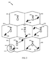
[0036]図2は、本開示の態様が実行され得る、LTEネットワークアーキテクチャにおけるアクセスネットワーク200の一例を示す図である。たとえば、UE206は、eIMTA LTEベースの通信の場合のCSI報告および測定において発生する衝突に対処するために、本明細書で説明する技法を利用し得る。
[0036] FIG. 2 is a diagram illustrating an example of an
[0037]図示の例では、アクセスネットワーク200は、いくつかのセルラー領域(セル)202に分割される。1つまたは複数のより低い電力クラスのeNB208(one or more lower power class eNBs 208)は、セル202のうちの1つまたは複数と重複するセルラー領域210を有し得る。より低い電力クラスのeNB208は、リモートラジオヘッド(RRH:remote radio head)と呼ばれることがある。より低い電力クラスのeNB208は、フェムトセル(たとえば、ホームeNB(HeNB))、ピコセル、またはマイクロセルであり得る。マクロeNB204は各々、それぞれのセル202に割り当てられ、セル202中のすべてのUE206のためにEPC110へのアクセスポイントを与えるように構成される。アクセスネットワーク200のこの例では集中コントローラはないが、代替構成では集中コントローラが使用され得る。eNB204は、無線ベアラ制御、承認制御、モビリティ制御、スケジューリング、セキュリティ、およびサービングゲートウェイ116への接続性を含む、すべての無線関係機能を担当する。ネットワーク200はまた、1つまたは複数のリレー(図示せず)を含み得る。一適用例によれば、UEはリレーとして働き得る。
In the illustrated example, the
[0038]アクセスネットワーク200によって採用される変調および多元接続方式は、展開されている特定の電気通信規格に応じて異なり得る。LTE適用例では、周波数分割複信(FDD:frequency division duplexing)と時分割複信(TDD)の両方をサポートするために、OFDMがDL上で使用され、SC−FDMAがUL上で使用される。当業者が以下の詳細な説明から容易に諒解するように、本明細書で提示する様々な概念はLTE適用例に好適である。ただし、これらの概念は、他の変調および多元接続技法を採用する他の電気通信規格に容易に拡張され得る。例として、これらの概念は、エボリューションデータオプティマイズド(EV−DO:Evolution-Data Optimized)またはウルトラモバイルブロードバンド(UMB)に拡張され得る。EV−DOおよびUMBは、CDMA2000規格ファミリーの一部として第3世代パートナーシッププロジェクト2(3GPP2:3rd Generation Partnership Project 2)によって公表されたエアインターフェース規格であり、移動局へのブロードバンドインターネットアクセスを提供するためにCDMAを採用する。これらの概念はまた、広帯域CDMA(W−CDMA(登録商標))とTD−SCDMAなどのCDMAの他の変形態とを採用するユニバーサル地上無線アクセス(UTRA:Universal Terrestrial Radio Access)、TDMAを採用するモバイル通信用グローバルシステム(GSM(登録商標):Global System for Mobile Communications)、ならびに、OFDMAを採用する、発展型UTRA(E−UTRA:Evolved UTRA)、ウルトラモバイルブロードバンド(UMB)、IEEE802.11(Wi−Fi(登録商標))、IEEE802.16(WiMAX(登録商標))、IEEE802.20、およびFlash−OFDM、に拡張され得る。UTRA、E−UTRA、UMTS、LTEおよびGSMは3GPP(登録商標)団体からの文書に記載されている。CDMA2000およびUMBは3GPP2団体からの文書に記載されている。採用される実際のワイヤレス通信規格および多元接続技術は、特定の適用例およびシステムに課される全体的な設計制約に依存することになる。
[0038] The modulation and multiple access schemes employed by the
[0039]eNB204は、MIMO技術をサポートする複数のアンテナを有し得る。MIMO技術の使用により、eNB204は、空間多重化、ビームフォーミング、および送信ダイバーシティをサポートするために空間領域を活用することが可能になる。空間多重化は、データの異なるストリームを同じ周波数上で同時に送信するために使用され得る。データストリームは、データレートを増加させるために単一のUE206に送信されるか、または全体的なシステム容量を増加させるために複数のUE206に送信され得る。これは、各データストリームを空間的にプリコーディングし(たとえば、振幅および位相のスケーリングを適用し)、次いでDL上で複数の送信アンテナを通して空間的にプリコーディングされた各ストリームを送信することによって達成される。空間的にプリコーディングされたデータストリームは、異なる空間シグネチャとともに(1つまたは複数の)UE206に到着し、これにより、(1つまたは複数の)UE206の各々は、そのUE206に宛てられた1つまたは複数のデータストリームを復元することが可能になる。UL上で、各UE206は、空間的にプリコーディングされたデータストリームを送信し、これにより、eNB204は、各空間的にプリコーディングされたデータストリームのソースを識別することが可能になる。
[0039] The
[0040]空間多重化は、概して、チャネル状態が良好であるときに使用される。チャネル状態があまり良好でないときは、送信エネルギーを1つまたは複数の方向に集中させるためにビームフォーミングが使用され得る。これは、複数のアンテナを通した送信のためのデータを空間的にプリコーディングすることによって達成され得る。セルのエッジにおいて良好なカバレージを達成するために、送信ダイバーシティと組み合わせてシングルストリームビームフォーミング送信が使用され得る。 [0040] Spatial multiplexing is generally used when channel conditions are good. When channel conditions are not very good, beamforming can be used to concentrate the transmit energy in one or more directions. This can be achieved by spatially precoding data for transmission through multiple antennas. Single stream beamforming transmission may be used in combination with transmit diversity to achieve good coverage at the edge of the cell.
[0041]以下の詳細な説明では、アクセスネットワークの様々な態様について、DL上でOFDMをサポートするMIMOシステムに関して説明する。OFDMは、OFDMシンボル内のいくつかのサブキャリアを介してデータを変調するスペクトラム拡散(spread-spectrum)技法である。サブキャリアは正確な周波数で離間される。離間は、受信機がサブキャリアからデータを復元することを可能にする「直交性(orthogonality)」を与える。時間領域では、OFDMシンボル間干渉をなくす(combat inter-OFDM-symbol interference)ために、ガードインターバル(a guard interval)(たとえば、サイクリックプレフィックス)が各OFDMシンボルに追加され得る。ULは、高いピーク対平均電力比(PAPR:peak-to-average power ratio)を補償するために、SC−FDMAをDFT拡散OFDM信号の形態で使用し得る。 [0041] In the detailed description that follows, various aspects of an access network will be described with respect to a MIMO system supporting OFDM on the DL. OFDM is a spread-spectrum technique that modulates data over several subcarriers within an OFDM symbol. The subcarriers are spaced at a precise frequency. Spacing provides “orthogonality” that allows the receiver to recover data from the subcarriers. In the time domain, a guard interval (eg, a cyclic prefix) may be added to each OFDM symbol to eliminate inter-OFDM-symbol interference. The UL may use SC-FDMA in the form of a DFT spread OFDM signal to compensate for a high peak-to-average power ratio (PAPR).
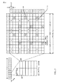
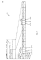
[0042]図3は、LTEにおけるDLフレーム構造の一例を示す図300である。フレーム(10ms)は、0〜9のインデックスをもつ等しいサイズの10個のサブフレームに分割され得る。各サブフレームは、2つの連続するタイムスロットを含み得る。2つのタイムスロットを表すためにリソースグリッドが使用され得、各タイムスロットはリソースブロックを含む。リソースグリッドは複数のリソース要素に分割される。LTEでは、リソースブロックは、周波数領域中に12個の連続するサブキャリアを含んでおり、各OFDMシンボル中のノーマルサイクリックプレフィックスについて、時間領域中に7個の連続するOFDMシンボル、または84個のリソース要素を含んでいる。拡張サイクリックプレフィックスについて、リソースブロックは、時間領域中に6個の連続するOFDMシンボルを含んでおり、72個のリソース要素を有する。R302、R304として示されるリソース要素のいくつかはDL基準信号(DL−RS:DL reference signal)を含む。DL−RSは、(共通RSと呼ばれることもある)セル固有RS(CRS:Cell-specific RS)302と、UE固有RS(UE−RS:UE-specific RS)304とを含む。UE−RS304は、対応する物理DL共有チャネル(PDSCH:physical DL shared channel)がマッピングされるリソースブロック上のみで送信される。各リソース要素によって搬送されるビット数は変調方式に依存する。したがって、UEが受信するリソースブロックが多いほど、また変調方式が高いほど、UEのためのデータレートは高くなる。
[0042] FIG. 3 is a diagram 300 illustrating an example of a DL frame structure in LTE. A frame (10 ms) may be divided into 10 equally sized subframes with indices 0-9. Each subframe may include two consecutive time slots. A resource grid may be used to represent two time slots, each time slot including a resource block. The resource grid is divided into a plurality of resource elements. In LTE, a resource block includes 12 consecutive subcarriers in the frequency domain, and for a normal cyclic prefix in each OFDM symbol, 7 consecutive OFDM symbols in the time domain, or 84 Contains resource elements. For the extended cyclic prefix, the resource block includes 6 consecutive OFDM symbols in the time domain and has 72 resource elements. Some of the resource elements indicated as R302 and R304 include a DL reference signal (DL-RS). The DL-RS includes a cell-specific RS (CRS) 302 (also referred to as a common RS) and a UE-specific RS (UE-RS) 304. The UE-
[0043]LTEでは、eNBは、eNB中の各セルについて1次同期信号(PSS:primary synchronization signal)と2次同期信号(SSS:secondary synchronization signal)とを送り得る。1次同期信号および2次同期信号は、それぞれ、ノーマルサイクリックプレフィックス(CP:cyclic prefix)をもつ各無線フレームのサブフレーム0および5の各々中のシンボル期間6および5において送られ得る。同期信号は、セル検出および捕捉のためにUEによって使用され得る。eNBは、サブフレーム0のスロット1中のシンボル期間0〜3において物理ブロードキャストチャネル(PBCH:Physical Broadcast Channel)を送り得る。PBCHはあるシステム情報を搬送し得る。
[0043] In LTE, an eNB may send a primary synchronization signal (PSS) and a secondary synchronization signal (SSS) for each cell in the eNB. The primary synchronization signal and the secondary synchronization signal may be sent in
[0044]eNBは、各サブフレームの最初のシンボル期間において物理制御フォーマットインジケータチャネル(PCFICH:Physical Control Format Indicator Channel)を送り得る。PCFICHは、制御チャネルのために使用されるシンボル期間の数(M)を搬送し得、ただし、Mは、1、2または3に等しくなり得、サブフレームごとに変化し得る。Mはまた、たとえば、リソースブロックが10個未満である、小さいシステム帯域幅では4に等しくなり得る。eNBは、各サブフレームの最初のM個のシンボル期間において物理HARQインジケータチャネル(PHICH:Physical HARQ Indicator Channel)と物理ダウンリンク制御チャネル(PDCCH:Physical Downlink Control Channel)とを送り得る。PHICHは、ハイブリッド自動再送要求(HARQ:hybrid automatic repeat request)をサポートするための情報を搬送し得る。PDCCHは、UEのためのリソース割振りに関する情報と、ダウンリンクチャネルのための制御情報とを搬送し得る。eNBは、各サブフレームの残りのシンボル期間において物理ダウンリンク共有チャネル(PDSCH)を送り得る。PDSCHは、ダウンリンク上でのデータ送信のためにスケジュールされたUEのためのデータを搬送し得る。 [0044] The eNB may send a Physical Control Format Indicator Channel (PCFICH) in the first symbol period of each subframe. PCFICH may carry the number of symbol periods (M) used for the control channel, where M may be equal to 1, 2 or 3, and may vary from subframe to subframe. M can also be equal to 4 for small system bandwidths, eg, with less than 10 resource blocks. The eNB may send a physical HARQ indicator channel (PHICH) and a physical downlink control channel (PDCCH) in the first M symbol periods of each subframe. The PHICH may carry information to support a hybrid automatic repeat request (HARQ). The PDCCH may carry information on resource allocation for the UE and control information for the downlink channel. The eNB may send a physical downlink shared channel (PDSCH) in the remaining symbol periods of each subframe. The PDSCH may carry data for UEs scheduled for data transmission on the downlink.
[0045]eNBは、eNBによって使用されるシステム帯域幅の中心1.08MHzにおいてPSS、SSS、およびPBCHを送り得る。eNBは、これらのチャネルが送られる各シンボル期間においてシステム帯域幅全体にわたってPCFICHおよびPHICHを送り得る。eNBは、システム帯域幅のいくつかの部分においてUEのグループにPDCCHを送り得る。eNBは、システム帯域幅の特定の部分において特定のUEにPDSCHを送り得る。eNBは、すべてのUEにブロードキャスト方式でPSS、SSS、PBCH、PCFICHおよびPHICHを送り得、特定のUEにユニキャスト方法でPDCCHを送り得、また特定のUEにユニキャスト方法でPDSCHを送り得る。 [0045] The eNB may send PSS, SSS, and PBCH at the center 1.08 MHz of the system bandwidth used by the eNB. The eNB may send PCFICH and PHICH over the entire system bandwidth in each symbol period in which these channels are sent. The eNB may send PDCCH to a group of UEs in some part of the system bandwidth. An eNB may send a PDSCH to a specific UE in a specific part of the system bandwidth. The eNB may send PSS, SSS, PBCH, PCFICH and PHICH to all UEs in a broadcast manner, may send PDCCH to a specific UE in a unicast manner, and may send PDSCH to a specific UE in a unicast manner.
[0046]各シンボル期間においていくつかのリソース要素が利用可能であり得る。各リソース要素(RE:resource element)は、1つのシンボル期間において1つのサブキャリアをカバーし得、実数値または複素数値であり得る1つの変調シンボルを送るために使用され得る。各シンボル期間において基準信号のために使用されないリソース要素は、リソース要素グループ(REG:resource element group)に構成され得る。各REGは、1つのシンボル期間中に4つのリソース要素を含み得る。PCFICHは、シンボル期間0において、周波数にわたってほぼ等しく離間され得る、4つのREGを占有し得る。PHICHは、1つまたは複数の構成可能なシンボル期間において、周波数にわたって拡散され得る、3つのREGを占有し得る。たとえば、PHICHのための3つのREGは、すべてシンボル期間0に属し得るか、またはシンボル期間0、1、および2において拡散され得る。PDCCHは、たとえば、最初のM個のシンボル期間において、利用可能なREGから選択され得る、9、18、36、または72個のREGを占有し得る。REGのいくつかの組合せのみがPDCCHに対して可能にされ得る。本方法および装置の態様において、サブフレームは、2つ以上のPDCCHを含み得る。
[0046] Several resource elements may be available in each symbol period. Each resource element (RE) may cover one subcarrier in one symbol period and may be used to send one modulation symbol, which may be real or complex valued. Resource elements that are not used for the reference signal in each symbol period may be configured into a resource element group (REG). Each REG may include four resource elements in one symbol period. The PCFICH may occupy four REGs that may be approximately equally spaced across the frequency in
[0047]UEは、PHICHおよびPCFICHのために使用される特定のREGを知り得る。UEは、PDCCHのためのREGの様々な組合せを探索し得る。探索すべき組合せの数は、一般に、PDCCHに対して可能にされる組合せの数よりも少ない。eNBは、UEが探索することになる組合せのいずれかにおいてUEにPDCCHを送り得る。 [0047] The UE may know the specific REG used for PHICH and PCFICH. The UE may search for various combinations of REGs for PDCCH. The number of combinations to search for is generally less than the number of combinations allowed for the PDCCH. The eNB may send the PDCCH to the UE in any of the combinations that the UE will search.
[0048]図4は、LTEにおけるULフレーム構造の一例を示す図400である。ULのための利用可能なリソースブロックは、データセクションと制御セクションとに区分され得る。制御セクションは、システム帯域幅の2つのエッジにおいて形成され得、構成可能なサイズを有し得る。制御セクション中のリソースブロックは、制御情報を送信するためにUEに割り当てられ得る。データセクションは、制御セクション中に含まれないすべてのリソースブロックを含み得る。ULフレーム構造は、単一のUEがデータセクション中の連続サブキャリアのすべてを割り当てられることを可能にし得る、連続サブキャリアを含むデータセクションを生じる。 [0048] FIG. 4 is a diagram 400 illustrating an example of a UL frame structure in LTE. Available resource blocks for the UL may be partitioned into a data section and a control section. The control section may be formed at two edges of the system bandwidth and may have a configurable size. Resource blocks in the control section may be allocated to the UE for transmitting control information. The data section may include all resource blocks that are not included in the control section. The UL frame structure results in a data section that includes consecutive subcarriers that may allow a single UE to be assigned all of the consecutive subcarriers in the data section.
[0049]UEは、eNBに制御情報を送信するために、制御セクション中のリソースブロック410a、410bを割り当てられ得る。UEは、eNBにデータを送信するために、データセクション中のリソースブロック420a、420bをも割り当てられ得る。UEは、制御セクション中の割り当てられたリソースブロック上の物理UL制御チャネル(PUCCH:physical UL control channel)中で制御情報を送信し得る。UEは、データセクション中の割り当てられたリソースブロック上の物理UL共有チャネル(PUSCH:physical UL shared channel)中でデータのみまたはデータと制御情報の両方を送信し得る。UL送信は、サブフレームの両方のスロットにわたり得、周波数上にわたってホッピングし得る。
[0049] The UE may be assigned
[0050]初期システムアクセスを実行し、物理ランダムアクセスチャネル(PRACH:physical random access channel)430中でUL同期を達成するために、リソースブロックのセットが使用され得る。PRACH430は、ランダムシーケンスを搬送し、いかなるULデータ/シグナリングも搬送することができない。各ランダムアクセスプリアンブルは、6つの連続するリソースブロックに対応する帯域幅を占有する。開始周波数はネットワークによって指定される。すなわち、ランダムアクセスプリアンブルの送信は、ある時間リソースおよび周波数リソースに制限される。周波数ホッピングはPRACHにはない。PRACH試みは単一のサブフレーム(1ms)中でまたは少数の連続サブフレームのシーケンス中で搬送され、UEはフレーム(10ms)ごとに単一のPRACH試みのみを行うことができる。
[0050] A set of resource blocks may be used to perform initial system access and achieve UL synchronization in a physical random access channel (PRACH) 430.
[0051]図5は、LTEにおけるユーザプレーンおよび制御プレーンのための無線プロトコルアーキテクチャの一例を示す図500である。UEおよびeNBのための無線プロトコルアーキテクチャは、レイヤ1と、レイヤ2と、レイヤ3との3つのレイヤとともに示されている。レイヤ1(L1レイヤ)は最下位レイヤであり、様々な物理レイヤ信号処理機能を実装する。L1レイヤを本明細書では物理レイヤ506と呼ぶ。レイヤ2(L2レイヤ)508は、物理レイヤ506の上にあり、物理レイヤ506を介したUEとeNBとの間のリンクを担当する。
[0051] FIG. 5 is a diagram 500 illustrating an example of a radio protocol architecture for a user plane and a control plane in LTE. The radio protocol architecture for the UE and eNB is shown with three layers:
[0052]ユーザプレーンでは、L2レイヤ508は、ネットワーク側のeNBにおいて終端される、媒体アクセス制御(MAC:media access control)サブレイヤ510と、無線リンク制御(RLC:radio link control)サブレイヤ512と、パケットデータコンバージェンスプロトコル(PDCP:packet data convergence protocol)514サブレイヤとを含む。図示されていないが、UEは、ネットワーク側のPDNゲートウェイ118において終端されるネットワークレイヤ(たとえば、IPレイヤ)と、接続の他端(たとえば、ファーエンドUE、サーバなど)において終端されるアプリケーションレイヤとを含めてL2レイヤ508の上にいくつかの上位レイヤを有し得る。
[0052] In the user plane, the
[0053]PDCPサブレイヤ514は、異なる無線ベアラと論理チャネルとの間の多重化を行う。PDCPサブレイヤ514はまた、無線送信オーバーヘッドを低減するための上位レイヤデータパケットのヘッダ圧縮と、データパケットを暗号化することによるセキュリティと、UEに対するeNB間のハンドオーバサポートとを与える。RLCサブレイヤ512は、上位レイヤデータパケットのセグメンテーションおよびリアセンブリと、紛失データパケットの再送信と、ハイブリッド自動再送要求(HARQ)による、順が狂った受信を補正するためのデータパケットの並べ替えとを行う。MACサブレイヤ510は、論理チャネルとトランスポートチャネルとの間の多重化を行う。MACサブレイヤ510はまた、UEの間で1つのセル内の様々な無線リソース(たとえば、リソースブロック)を割り振ることを担当する。MACサブレイヤ510はまたHARQ動作を担当する。
[0053] The
[0054]制御プレーンでは、UEおよびeNBのための無線プロトコルアーキテクチャは、制御プレーンのためのヘッダ圧縮機能がないことを除いて、物理レイヤ506およびL2レイヤ508について実質的に同じである。制御プレーンはまた、レイヤ3(L3レイヤ)中に無線リソース制御(RRC:radio resource control)サブレイヤ516を含む。RRCサブレイヤ516は、無線リソース(すなわち、無線ベアラ)を取得することと、eNBとUEとの間のRRCシグナリングを使用して下位レイヤを構成することとを担当する。
[0054] In the control plane, the radio protocol architecture for the UE and eNB is substantially the same for the
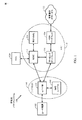
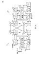
[0055]図6は、本開示の態様が実行され得るアクセスネットワークにおいてUE650と通信しているeNB610のブロック図である。たとえば、UE650は、eIMTA LTEベースの通信の場合のCSI報告および測定において発生する衝突に対処するために、本明細書で説明する技法を利用し得る。
[0055] FIG. 6 is a block diagram of an
[0056]DLでは、コアネットワークからの上位レイヤパケットが、コントローラ/プロセッサ675に与えられる。コントローラ/プロセッサ675は、L2レイヤの機能を実装する。DLでは、コントローラ/プロセッサ675は、様々な優先度メトリックに基づいて、ヘッダ圧縮と、暗号化と、パケットのセグメンテーションおよび並べ替えと、論理チャネルとトランスポートチャネルとの間の多重化と、様々な優先度メトリックに基づくUE650への無線リソース割振りとを行う。コントローラ/プロセッサ675はまた、HARQ動作と、紛失パケットの再送信と、UE650へのシグナリングとを担当する。
[0056] In DL, upper layer packets from the core network are provided to the controller /
[0057]TXプロセッサ616は、L1レイヤ(すなわち、物理レイヤ)のための様々な信号処理機能を実装する。信号処理機能は、UE650における前方誤り訂正(FEC:forward error correction)を容易にするためのコーディングおよびインターリービングと、様々な変調方式(たとえば、2位相シフトキーイング(BPSK:binary phase-shift keying)、4位相シフトキーイング(QPSK:quadrature phase-shift keying)、M位相シフトキーイング(M−PSK:M-phase-shift keying)、多値直交振幅変調(M−QAM:M-quadrature amplitude modulation))に基づいた信号コンスタレーションへのマッピングとを含む。コーディングされ、変調されたシンボルは、次いで、並列ストリームに分割される。各ストリームは、次いでOFDMサブキャリアにマッピングされ、時間領域および/または周波数領域中で基準信号(たとえば、パイロット)と多重化され、次いで逆高速フーリエ変換(IFFT:Inverse Fast Fourier Transform)を使用して互いに組み合わされて、時間領域OFDMシンボルストリームを搬送する物理チャネルが生成される。OFDMストリームは、複数の空間ストリームを生成するために空間的にプリコーディングされる。チャネル推定器674からのチャネル推定値は、コーディングおよび変調方式を決定するために、ならびに空間処理のために使用され得る。チャネル推定値は、UE650によって送信される基準信号および/またはチャネル状態フィードバックから導出され得る。各空間ストリームは、次いで、別個の送信機618TXを介して異なるアンテナ620に与えられる。各送信機618TXは、送信のためにそれぞれの空間ストリームでRFキャリアを変調する。
[0057] The TX processor 616 implements various signal processing functions for the L1 layer (ie, physical layer). Signal processing functions include coding and interleaving to facilitate forward error correction (FEC) at
[0058]UE650において、各受信機654RXは、それのそれぞれのアンテナ652を通して信号を受信する。各受信機654RXは、RFキャリア上に変調された情報を復元し、受信機(RX)プロセッサ656に情報を与える。RXプロセッサ656はL1レイヤの様々な信号処理機能を実装する。RXプロセッサ656は、UE650に宛てられた任意の空間ストリームを復元するために、情報に対して空間処理を実行する。複数の空間ストリームがUE650に宛てられた場合、それらはRXプロセッサ656によって単一のOFDMシンボルストリームに組み合わされ得る。RXプロセッサ656は、次いで、高速フーリエ変換(FFT:Fast Fourier Transform)を使用してOFDMシンボルストリームを時間領域から周波数領域に変換する。周波数領域信号は、OFDM信号のサブキャリアごとに別々のOFDMシンボルストリームを備える。各サブキャリア上のシンボルと基準信号とは、eNB610によって送信される、可能性が最も高い信号コンスタレーションポイントを決定することによって復元され、復調される。これらの軟判定は、チャネル推定器658によって計算されるチャネル推定値に基づき得る。軟判定は、次いで、物理チャネル上でeNB610によって最初に送信されたデータと制御信号とを復元するために復号され、デインターリーブされる。データおよび制御信号は、次いで、コントローラ/プロセッサ659に与えられる。
[0058] At
[0059]コントローラ/プロセッサ659はL2レイヤを実装する。コントローラ/プロセッサは、プログラムコードとデータとを記憶するメモリ660に関連付けられ得る。メモリ660はコンピュータ可読媒体と呼ばれることがある。ULでは、制御/プロセッサ659は、コアネットワークからの上位レイヤパケットを復元するために、トランスポートチャネルと論理チャネルとの間の多重分離(demultiplexing)と、パケットリアセンブリと、解読(deciphering)と、ヘッダ復元(decompression)と、制御信号処理とを行う。上位レイヤパケットは、次いで、L2レイヤの上のすべてのプロトコルレイヤを表す、データシンク662に与えられる。また、様々な制御信号がL3処理のためにデータシンク662に与えられ得る。コントローラ/プロセッサ659はまた、HARQ動作をサポートするために肯定応答(ACK)および/または否定応答(NACK)プロトコルを使用した誤り検出を担当する。
[0059] The controller /
[0060]ULでは、データソース667は、コントローラ/プロセッサ659に上位レイヤパケットを与えるために使用される。データソース667は、L2レイヤの上のすべてのプロトコルレイヤを表す。eNB610によるDL送信に関して説明した機能と同様に、コントローラ/プロセッサ659は、ヘッダ圧縮と、暗号化と、パケットのセグメント化および並べ替えと、eNB610による無線リソース割振りに基づいた論理チャネルとトランスポートチャネルとの間の多重化とを行うことによって、ユーザプレーンおよび制御プレーンのためのL2レイヤを実装する。コントローラ/プロセッサ659はまた、HARQ動作と、紛失パケットの再送信と、eNB610へのシグナリングとを担当する。
[0060] In the UL, the
[0061]eNB610によって送信される基準信号またはフィードバックからの、チャネル推定器658によって導出されるチャネル推定値は、適切なコーディングおよび変調方式を選択することと、空間処理を容易にすることとを行うために、TXプロセッサ668によって使用され得る。TXプロセッサ668によって生成される空間ストリームは、別個の送信機654TXを介して異なるアンテナ652に与えられる。各送信機654TXは、送信のためにそれぞれの空間ストリームでRFキャリアを変調する。
[0061] Channel estimates derived by
[0062]UL送信は、UE650における受信機機能に関して説明した方法と同様の方法でeNB610において処理される。各受信機618RXは、それのそれぞれのアンテナ620を通して信号を受信する。各受信機618RXは、RFキャリア上で変調された情報を復元し、RXプロセッサ670にその情報を与える。RXプロセッサ670はL1レイヤを実装し得る。
[0062] The UL transmission is processed at the
[0063]コントローラ/プロセッサ675はL2レイヤを実装する。コントローラ/プロセッサ675は、プログラムコードとデータとを記憶するメモリ676に関連付けられ得る。メモリ676はコンピュータ可読媒体と呼ばれることがある。ULでは、制御/プロセッサ675は、UE650からの上位レイヤパケットを復元するために、トランスポートチャネルと論理チャネルとの間の多重分離と、パケットリアセンブリと、解読と、ヘッダ復元と、制御信号処理とを行う。コントローラ/プロセッサ675からの上位レイヤパケットはコアネットワークに与えられ得る。コントローラ/プロセッサ675はまた、HARQ動作をサポートするためにACKおよび/またはNACKプロトコルを使用した誤り検出を担当する。
[0063] The controller /
[0064]コントローラ/プロセッサ675、659は、本開示のいくつかの態様に従って動作するように、それぞれ、eNB610およびUE650における動作を指示し得る。たとえば、UE650におけるコントローラ/プロセッサ659および/または他のプロセッサおよびモジュールは、図11に示されている動作1100および/または図13に示されている動作1300を実行するか、あるいはUEにそれらの動作を実行するように指示し得る。同様に、eNB610におけるコントローラ/プロセッサ675および/または他のプロセッサおよびモジュールは、図10に示されている動作1000を実行するか、あるいはeNB610にそれらの動作を実行するように指示し得る。
[0064] Controllers /
例示的なサブフレーム構成
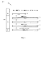
[0065]図7に、LTE TDDのための例示的なフレーム構造700を示す。図7に示されているように、10ms無線フレーム702は、等しい長さ(たとえば、5ms)の2つのハーフ・フレーム704からなり、各ハーフ・フレームは、10個のスロット、または8つのスロット(たとえば、スロット706)+スペシャルサブフレーム708中の3つのスペシャルフィールド、DwPTS(ダウンリンクパイロットタイムスロット(downlink pilot time slot))と、GP(ガード期間(guard period))と、UpPTS(アップリンクパイロットタイムスロット(uplink pilot time slot))とからなる。各スロット706は長さが0.5msであり、2つの連続するスロットは、ちょうど1つのサブフレーム710を形成する。
Exemplary subframe configuration
[0065] FIG. 7 shows an exemplary frame structure 700 for LTE TDD. As shown in FIG. 7, a 10
[0066]無線フレーム内で、LTE TDDは、ダウンリンク送信とアップリンク送信との間で複数回切り替わり、その逆も同様である。ガード期間(GP)は、ダウンリンクからアップリンクに切り替わるときにDwPTSとUpPTSとの間に挿入される。GPの持続時間は、基地局から移動局へのおよびその逆の信号伝搬時間、ならびに移動局が受信することから送ることに切り替わるのに必要な時間に依存する。個々のスペシャルフィールドの長さは、ネットワークによって選択されたアップリンク/ダウンリンク構成に依存するが、3つのスペシャルフィールドの全長は1msの一定のままである。 [0066] Within a radio frame, LTE TDD switches multiple times between downlink and uplink transmissions, and vice versa. The guard period (GP) is inserted between DwPTS and UpPTS when switching from the downlink to the uplink. The duration of the GP depends on the signal propagation time from the base station to the mobile station and vice versa, and the time required for the mobile station to switch from receiving to sending. The length of the individual special fields depends on the uplink / downlink configuration selected by the network, but the total length of the three special fields remains constant at 1 ms.
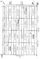
[0067]LTE TDDでは、送信方向は、異なるサブフレーム中でULデータおよびDLデータを搬送することによって分離される。図8の表800に示されているように、7つの可能なDLおよびULサブフレーム構成がサポートされる。 [0067] In LTE TDD, the transmission direction is separated by carrying UL data and DL data in different subframes. As shown in table 800 of FIG. 8, seven possible DL and UL subframe configurations are supported.
[0068]テーブル800の列802に示されているように、7つのUL/DL構成はインデックス0〜6によって識別される。列806に示されているように、サブフレーム中の「D」はDLデータ送信を示し、「U」はULデータ送信を示し、「S」は、図7に関して上記で説明したように、スペシャルフィールドDwPTSとGPとUpPTSとを有するスペシャルサブフレームを示す。列804に示されているように、2つの切替え周期性、5msおよび10msがある。5ms周期性(たとえば、サブフレーム構成0〜2および6)の場合、図7に示されているように、1つの10msフレーム中に2つのスペシャルサブフレームがある。10ms周期性(たとえば、サブフレーム構成3〜5)の場合、1つのフレーム中に1つのスペシャルサブフレームがある。
[0068] As shown in
LTEにおけるeIMTAのための2つのサブフレームセットのCSIフィードバック
[0069]動的サブフレーム構成をサポートするUEは、eIMTAの場合と同様に、CSIを測定および報告するときに、いくつかの課題を有し得る。本開示の態様は、動的サブフレーム再構成をサポートすることが可能なUEによるCSI報告のために使用され得る技法を提供する。
CSI feedback of two subframe sets for eIMTA in LTE
[0069] A UE that supports dynamic subframe configuration may have several challenges when measuring and reporting CSI, as in eIMTA. Aspects of this disclosure provide techniques that may be used for CSI reporting by UEs capable of supporting dynamic subframe reconfiguration.
[0070]CSI報告を容易にするために、いくつかの規格(たとえば、LTEリリース11)は、eNBが干渉状態を決定するのを助け得る測定値をUEが報告することを可能にするUE固有な干渉測定リソース(IMR)を導入している。場合によっては、UEは、subframeConfigパラメータおよびresourceConfigパラメータなどのいくつかのパラメータに基づいて別個のIMRで構成され得る。subframeConfigパラメータは、どのサブフレームがIMRを含んでいるかをシグナリングし、一緒にコーディングされた周期性およびサブフレームオフセットを有する。resourceConfigパラメータは、どのリソース要素(RE)が、非ゼロ電力(NZP:non-zero-power)チャネル状態情報基準信号(CSI−RS:channel state information reference signal)リソースによって占有されるか(すなわち、どのパターンが使用されるか)を識別する。 [0070] To facilitate CSI reporting, some standards (eg, LTE Release 11) allow UEs to report measurements that can help eNBs determine interference conditions. New interference measurement resource (IMR) has been introduced. In some cases, the UE may be configured with a separate IMR based on a number of parameters such as a subframeConfig parameter and a resourceConfig parameter. The subframeConfig parameter signals which subframe contains the IMR and has a periodicity and subframe offset coded together. The resourceConfig parameter indicates which resource element (RE) is occupied by a non-zero-power (NZP) channel state information reference signal (CSI-RS) resource (ie, which one). Identify if a pattern is used).
[0071]従来のシステムでは、IMRスケジューリングは追加の制約を受け得る。たとえば、第1の制約は、1つのUEのために構成されたすべてのIMRが、特定のUEのために実際に構成されることも構成されないこともある1つの仮想ゼロ電力(ZP:zero-power)CSI−RS構成のサブセットであり得るということである。第2の制約は、UEのために構成された各IMRが、そのUEのための少なくとも1つの構成されたZP CSI−RSリソースによってカバーされ得るが、UEのために構成されたIMRは、必ずしも同じZP CSI−RS構成によってカバーされなければならないとは限らないということである。 [0071] In conventional systems, IMR scheduling may be subject to additional constraints. For example, the first constraint is that all IMRs configured for one UE may actually be configured or not configured for a particular UE, one virtual zero power (ZP). power) may be a subset of the CSI-RS configuration. The second constraint is that each IMR configured for a UE can be covered by at least one configured ZP CSI-RS resource for that UE, but the IMR configured for the UE is not necessarily This does not necessarily have to be covered by the same ZP CSI-RS configuration.
[0072]図9に示されているように、第1の制約は、すべてのIMRが5msグリッド上に位置する(fall onto a 5ms grid)ことを要求する。たとえば、図9は、上記の第1の制約により、IMRが可能にされるときの2つのシナリオと、IMRが可能にされないときの1つのシナリオとを示している。シナリオ1において見られ得るように、2つのIMR(IMR1およびIMR2)は、それらが両方とも同時に同じサブフレーム中に位置し、5msの倍数にあるときに可能にされ得る。シナリオ2は、IMR1とIMR2が5msグリッド上に互い違いに配置される(staggered on a 5ms grid)とき、それらが可能にされることを示す。たとえば、IMR1は0msに位置し(falls at 0ms)、IMR2は5msに位置する。シナリオ3は、2つのIMRが5msグリッド上に位置しないので、IMRが可能にされないときの一例を示している。
[0072] As shown in FIG. 9, the first constraint requires that all IMRs fall onto a 5ms grid. For example, FIG. 9 shows two scenarios when IMR is enabled due to the first constraint above, and one scenario when IMR is not enabled. As can be seen in
[0073]上述のように、eIMTAを使用すると、実際のトラフィックニーズに基づいて、および/または干渉管理のために、TDD DL/ULサブフレーム構成を動的に適応させることが可能であり得る。たとえば、短い持続時間中に、ダウンリンク上で大きいデータバーストが必要とされる場合、サブフレーム構成は、たとえば、6つのDLサブフレームと4つのULサブフレームとを有する構成#1から、9つのDLサブフレームと1つのULサブフレームとを有する構成#5に変更され得る。場合によっては、TDD構成の適応は640msよりも遅くならないことが予想される。極端な場合、その適応は10ms程度に高速になり得る。
[0073] As described above, using eIMTA, it may be possible to dynamically adapt the TDD DL / UL subframe configuration based on actual traffic needs and / or for interference management. For example, if a large data burst is required on the downlink during a short duration, the subframe configuration is, for example, from
[0074]場合によっては、eIMTAの場合、2つのサブフレームセットのいずれかのための別個のチャネル状態情報(CSI)測定/報告を可能にするために、最高2つのサブフレームセットがUE固有にシグナリングされ得る。しかしながら、2つのタイプのサブフレームについてのCSI測定/報告をサポートするために、(すべてのIMRが5msグリッド上に位置するという)第1のIMR制約は、eIMTAの場合、取り除かれる必要があり得る。したがって、少なくともeIMTA対応UEの場合、この制約がいつ取り除かれ得るかを定義する必要があり得る。 [0074] In some cases, for eIMTA, up to two subframe sets are UE-specific to allow separate channel state information (CSI) measurement / reporting for either of the two subframe sets. Can be signaled. However, to support CSI measurement / reporting for two types of subframes, the first IMR constraint (all IMRs are located on a 5ms grid) may need to be removed in the case of eIMTA. . Thus, at least for eIMTA capable UEs, it may be necessary to define when this constraint can be removed.
[0075]図10に、本開示の態様による、ワイヤレス通信のための例示的な動作1000を示す。態様によれば、動作1000は、基地局(たとえば、eノードB)によって実行され得る。
[0075] FIG. 10 illustrates an
[0076]動作1000は、1002において、ユーザ機器(UE)に第1のアップリンク/ダウンリンク(UL/DL)サブフレーム構成をシグナリングすることから開始する。1004において、BSは、第2のUL/DLサブフレーム構成を動的にシグナリングする。1006において、BSは少なくとも第1および第2の干渉測定リソース(IMR)でUEを構成し、ここにおいて、第1および第2のIMRのうちの少なくとも1つは、IMRが周期的に発生するサブフレームに限定されるという制約を受けない。
[0076]
[0077]図11に、本開示の態様による、ワイヤレス通信のための例示的な動作1100を示す。態様によれば、動作1100は、UEによって実行され得る。
[0077] FIG. 11 illustrates an
[0078]動作1100は、1102において、基地局(BS)と通信するための第1のアップリンク/ダウンリンク(UL/DL)サブフレーム構成のシグナリングを受信することから開始する。1104において、UEは、BSから第2のUL/DLサブフレーム構成の動的シグナリングを受信する。1106において、UEは少なくとも第1および第2の干渉測定リソース(IMR)の構成を受信し、ここにおいて、第1および第2のIMRのうちの少なくとも1つは、IMRが周期的に発生するサブフレームに限定されるという制約を受けない。
[0078]
[0079]本開示のいくつかの態様によれば、IMRに対する1つまたは複数の制約は取り除かれ得る。たとえば、場合によっては、IMRが5msグリッドに従わなければならないという制約は、eIMTA対応UEについて取り除かれ得る。場合によっては、この制約は、(ULからDLおよびその逆に動的に変更され得る指示をもつサブフレームを指す)フレキシブルサブフレーム中でのみ取り除かれ得る。しかしながら、場合によっては、レガシーユーザを適用させるのを助けるために、すべてのIMRが5msグリッド上に位置することを必要とし続けることは有益であり得る。 [0079] According to some aspects of the present disclosure, one or more constraints on the IMR may be removed. For example, in some cases, the constraint that the IMR must follow a 5ms grid may be removed for eIMTA capable UEs. In some cases, this constraint can only be removed in flexible subframes (pointing to subframes with instructions that can be dynamically changed from UL to DL and vice versa). However, in some cases it may be beneficial to continue to require that all IMRs be located on a 5 ms grid to help apply legacy users.
[0080]しかしながら、レガシーUEによって認識されないフレキシブルサブフレーム1202など、SIB1シグナリングされた構成中で(in a SIB1 signaled configuration)DLサブフレームに指定されないサブフレーム中に第2のIMR(IMR−2)を配置することが可能であり得る。たとえば、図12は、5msグリッドに従わないフレキシブルサブフレーム1202中にIMR−2を配置する(place)ことが可能であり得ることを示している。いくつかの態様によれば、非SIB1サブフレーム中にIMR−2を配置することは、eIMTAをサポートすることが可能なUEに2つのIMR構成だけが適用することを保証し得る。
[0080] However, in a SIB1 signaled configuration, such as a
CSI報告衝突処理
[0081]上述のように、eIMTAは、チャネル状態情報(CSI)測定および報告において問題を生じ得る。
CSI report collision handling
[0081] As mentioned above, eIMTA can cause problems in channel state information (CSI) measurement and reporting.
[0082]たとえば、いくつかのサブフレーム構成およびCSI報告構成の場合、異なるCSI報告プロセスのためのCSI測定値が(本明細書では「衝突」と呼ぶ)同じULサブフレーム中で報告されるように構成され得る。これは、たとえば、1つのULサブフレーム中で単一の報告のみが送られ得るシナリオにおいて問題を提示し得る。本開示の態様は、どの測定値が報告されるべきであるかに優先度を付けるための技法を提供する。 [0082] For example, for several subframe configurations and CSI reporting configurations, CSI measurements for different CSI reporting processes may be reported in the same UL subframe (referred to herein as “collisions”). Can be configured. This may present a problem, for example, in a scenario where only a single report may be sent in one UL subframe. Aspects of the present disclosure provide techniques for prioritizing which measurements should be reported.
[0083]さらに、様々な理由により、UEは、CSI測定を実行するために有効なDLサブフレームを検出することができないことがある(または有効なDLサブフレームがないことがある)。たとえば、eIMTAにより、CSI測定のためのリソースを搬送するように構成されたDLサブフレームは、ULサブフレームに動的に変更され得る。本開示の態様は、現在のサブフレーム構成が現在のCSI構成に一致せず(または「衝突し」)、それにより「衝突」とも考えられ得るような場合に、CSIをどのように報告すべきかを決定するための技法を提供する。 [0083] Furthermore, for various reasons, the UE may not be able to detect a valid DL subframe to perform CSI measurements (or may not have a valid DL subframe). For example, a DL subframe configured to carry resources for CSI measurement by eIMTA may be dynamically changed to a UL subframe. Aspects of this disclosure describe how CSI should be reported when the current subframe configuration does not match the current CSI configuration (or “collision”), and can thus be considered a “collision”. Provides a technique for determining
[0084]図13に、本開示の態様による、ワイヤレス通信のための例示的な動作1300を示す。動作1300は、たとえば、eIMTAをサポートすることが可能なUEによって実行され得る。
[0084] FIG. 13 illustrates an
[0085]動作1300は、1302において、基地局(BS)と通信するための第1のアップリンク/ダウンリンク(UL/DL)サブフレーム構成のシグナリングを受信することから開始する。1304において、UEは、少なくとも2つのサブフレームセットを示す少なくとも1つのチャネル状態情報(CSI)報告構成のシグナリングを受信し、ここで、各サブフレームセットは干渉測定リソース(IMR)構成に関連する。1306において、UEは、アップリンクサブフレーム中の少なくとも2つのサブフレームセットについてのCSI報告の衝突を検出する。1308において、UEは、アップリンクサブフレーム中のCSI報告のために少なくとも2つのサブフレームセットからの1つのサブフレームセットに優先度を付ける。1310において、UEは、優先度付けに基づいてアップリンクサブフレーム中でCSIを報告する。
[0085]
[0086]上記で説明したように、2つのサブフレームセットについての周期CSI報告も、eIMTAの下でサポートされ得る。いくつかの態様によれば、2つのサブフレームセットについてのCSI報告間の衝突がある(すなわち、各サブフレームセットが、同じULサブフレーム中で報告するように構成された)とき、サブフレームセットのうちの一方は、報告するための優先度を与えられ得る。 [0086] As described above, periodic CSI reporting for two subframe sets may also be supported under eIMTA. According to some aspects, when there is a collision between CSI reports for two subframe sets (ie, each subframe set is configured to report in the same UL subframe), the subframe set One of the may be given priority for reporting.
[0087]場合によっては、(再構成され得る「フレキシブル」サブフレームとは対照的に、DLサブフレームとして「固定された」サブフレーム上で測定されるべきCSIをもつ)固定サブフレームセットCSIは、より高い優先度を与えられ得る。これは、PUCCH上で送られる周期CSI報告の場合、1つの報告のみがPUCCH上で送信され得、すべての他の報告がドロップされ得るので、必要であり得る。 [0087] In some cases, a fixed subframe set CSI (with CSI to be measured on a "fixed" subframe as a DL subframe as opposed to a "flexible" subframe that can be reconfigured) is , May be given higher priority. This may be necessary for periodic CSI reports sent on the PUCCH, since only one report may be sent on the PUCCH and all other reports may be dropped.
[0088]本開示の態様は、周期CSIプロセス間の衝突が検出されたときの報告に優先度を付ける異なるオプションを提供する。たとえば、コンポーネントキャリア(CC:component carrier)内の衝突の場合、優先度付けは、以下の順序に基づいて実行され得る。最初に報告タイプ(たとえば、RI/PTI/CQI)を考慮し、次いでCSIサブフレームセット(たとえば、CSI0またはCSI1)を考慮し、次いでCSIプロセスインデックスを考慮する。様々なCCにわたる衝突の場合、キャリアアグリゲーション(CA:carrier aggregation)を用いたeIMTAのために、優先度付けはまた、特定のCCを考慮し得る。たとえば、CA eIMTAのための優先度付けは、以下の順序に基づいて実行され得る。最初に報告タイプを考慮し、次いでCSIサブフレームセットを考慮し、次いでCSIプロセスインデックスを考慮し、最終的にCCインデックスを考慮する。いくつかの態様によれば、固定サブフレームについてのCSI報告はCSIプロセスID#0と見なされ得、それにより、既存の衝突処理ルールがeIMTAのために再利用されることを可能にし得る。
[0088] Aspects of the present disclosure provide different options for prioritizing reporting when a collision between periodic CSI processes is detected. For example, for a collision within a component carrier (CC), prioritization may be performed based on the following order: First consider the report type (eg, RI / PTI / CQI), then consider the CSI subframe set (eg, CSI0 or CSI1), and then consider the CSI process index. For collisions across different CCs, prioritization may also take into account specific CCs for eIMTA with carrier aggregation (CA). For example, prioritization for CA eIMTA may be performed based on the following order: Consider first the report type, then the CSI subframe set, then the CSI process index, and finally the CC index. According to some aspects, CSI reporting for fixed subframes may be considered CSI
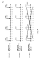
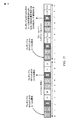
[0089]図14に、CSI報告のための2つのサブフレームセット間の衝突の一例を示す。図示の例では、第1のサブフレームセット(サブフレームセット1)は10ms報告周期性を有し、サブフレーム2、12、22などにおいてCSI測定値を報告するために構成される。第2のサブフレームセット(サブフレームセット2)は5ms CSI報告周期性を有し、サブフレーム2、7、12、22などにおいてCSI測定値を報告するように構成される。したがって、図示のように、サブフレームセット1および2は両方とも、サブフレーム2、12および22中でCSIを報告するように構成され、その結果、衝突を生じる。
[0089] FIG. 14 shows an example of a collision between two subframe sets for CSI reporting. In the illustrated example, the first subframe set (subframe set 1) has a 10 ms reporting periodicity and is configured to report CSI measurements in
[0090]上述のように、両方のサブフレームセットが同じULサブフレーム中でCSI測定値を報告するように構成されたとき、サブフレームセット間の衝突が発生し得る。この衝突を解決するために、UEは、衝突するULサブフレーム中のCSI報告のためにどのサブフレームセットが優先度を付けられるべきかを決定し得る。1つのサブフレームセットのみ(たとえば、サブフレームセット2)が特定のULサブフレーム(たとえば、UL SF7、17、および27)内でCSI測定値を報告するように構成されたとき、衝突は発生せず、UEは、そのサブフレームセットについてのCSIを報告し得る。
[0090] As described above, collisions between subframe sets may occur when both subframe sets are configured to report CSI measurements in the same UL subframe. To resolve this collision, the UE may determine which set of subframes should be prioritized for CSI reporting in the colliding UL subframe. A collision does not occur when only one subframe set (eg, subframe set 2) is configured to report CSI measurements within a particular UL subframe (eg,
[0091]周期CSI(P−CSI:periodic CSI)報告と非周期CSI(A−CSI:aperiodic CSI)(すなわち、非周期)報告の両方のために、UEは、CSIを測定するために(基準信号のために割り振られたリソースをもつ)有効なDLサブフレームを必要とし得る。たとえば、DLサブフレームが、特定のUEのためのダウンリンクサブフレームとして構成され、その特定のUEのための構成された測定ギャップ内に入らず、CSI報告にリンクされたCSIサブフレームセットの要素である場合、そのDLサブフレームは有効であると見なされ得る。いくつかの態様によれば、サービングセル中にCSI測定のための有効なダウンリンクサブフレームがない場合、(そのCSIが報告されていたであろう)対応するアップリンクサブフレーム中でサービングセルについてのCSI報告が省略され得る。 [0091] For both periodic CSI (P-CSI) and aperiodic CSI (A-CSI) (ie, aperiodic CSI) reports, the UE uses (reference) It may require a valid DL subframe (with resources allocated for signaling). For example, an element of a CSI subframe set in which a DL subframe is configured as a downlink subframe for a particular UE, does not fall within the configured measurement gap for that particular UE, and is linked to a CSI report The DL subframe may be considered valid. According to some aspects, if there is no valid downlink subframe for CSI measurement in the serving cell, the CSI for the serving cell in the corresponding uplink subframe (that CSI would have been reported). Reporting can be omitted.
[0092]いくつかの態様によれば、通常TDD動作の場合、DLサブフレームが有効であるかどうかを決定するパラメータは半静的に構成され得、それにより、eNBとUEとの間のあいまいさを低減する。しかしながら、TDD eIMTAの場合、ULとDLとの間のサブフレーム指示の動的構成があり得る。UEが動的構成のためのレイヤ1(L1)シグナリングを復号することができない場合、サブフレーム指示に関して、eNBとUEとの間に不整合(misalignment)が発生し、したがって、CSI測定および報告に影響を及ぼし得る。たとえば、eNBは、UEがCSI測定を行うことを予想される少なくとも1つのDLサブフレームを含む新しいサブフレーム構成をUEに動的にシグナリングし得る。しかしながら、UEが動的シグナリングを適切に復号することができない場合、UEは、少なくとも1つのDLサブフレームがULサブフレームであると考えることがあり、CSI測定を行うことができないことがある。 [0092] According to some aspects, for normal TDD operation, the parameters that determine whether a DL subframe is valid may be configured semi-statically, thereby enabling ambiguity between the eNB and the UE. To reduce. However, for TDD eIMTA, there can be a dynamic configuration of subframe indications between UL and DL. If the UE is unable to decode layer 1 (L1) signaling for dynamic configuration, a misalignment occurs between the eNB and the UE with respect to the subframe indication, and thus in CSI measurement and reporting May have an impact. For example, the eNB may dynamically signal a new subframe configuration including at least one DL subframe in which the UE is expected to make CSI measurements to the UE. However, if the UE is unable to properly decode dynamic signaling, the UE may consider at least one DL subframe to be a UL subframe and may not be able to make CSI measurements.
[0093]TDD eIMTAの場合、CSI測定のための様々な手法が使用され得る。1つの手法によれば、UEが再構成の明示的L1シグナリングを正しく復号し、有効なUL−DL構成を検出したとき、UEは、再構成の明示的L1シグナリングによってDLサブフレームまたはスペシャルサブフレームとして示されるサブフレーム内でのみCSIを測定し得る。一方、UEが無線フレームのための有効なUL−DL構成を搬送するL1シグナリングを検出しなかった場合、UEは、SIB構成によってDLサブフレームまたはスペシャルサブフレームとして示されるサブフレーム内でのみCSIを測定し得、それは、フォールバック動作と見なされ得る(すなわち、UEがL1シグナリングを復号することができないとき、UEはSIB構成にフォールバックし得る)。 [0093] For TDD eIMTA, various techniques for CSI measurement may be used. According to one approach, when the UE correctly decodes the reconfigured explicit L1 signaling and detects a valid UL-DL configuration, the UE may perform a DL subframe or a special subframe via the reconfigured explicit L1 signaling. CSI may be measured only within the subframes indicated as. On the other hand, if the UE does not detect L1 signaling carrying a valid UL-DL configuration for a radio frame, the UE will only receive CSI in the subframe indicated by the SIB configuration as a DL subframe or a special subframe. May be considered a fallback operation (ie, when the UE is unable to decode L1 signaling, the UE may fall back to the SIB configuration).
[0094]しかしながら、CSI報告に対する上記の手法は、UEが有効なUL/DL構成を搬送するL1シグナリングを検出しない場合、フレキシブルDLサブフレームについてのCSIが省略されることになり得る。これは、UEによって報告されるCSIを予想するが、(たとえば、上記で説明したフォールバック動作により)UEからCSI報告を実際に受信しないeNBに対してあいまいさを生じ得る。これはまた、PUSCHデータレートマッチングが、CSI報告のためにアグリゲートされたCSIビットの数とアグリゲートされたCCの数とに大いに依存するので、特に、1つのUEのために構成された複数のコンポーネントキャリア(CC)の場合、CSIがPUSCH上に多重化されたとき、PUSCH復号に影響を及ぼし得る。 [0094] However, the above approach to CSI reporting may result in CSI for flexible DL subframes being omitted if the UE does not detect L1 signaling carrying a valid UL / DL configuration. This may cause ambiguity for eNBs that expect CSI to be reported by the UE, but do not actually receive a CSI report from the UE (eg, due to the fallback operation described above). This is also especially true for PUSCH data rate matching, since it depends heavily on the number of CSI bits aggregated and the number of CCs aggregated for CSI reporting. In the case of multiple component carriers (CC), PUSCH decoding may be affected when CSI is multiplexed on PUSCH.
[0095]いくつかの態様によれば、UEは、測定すべき有効なDLサブフレームを有しないとき、どのように報告すべきかを決定するためのアクションを取り得る。たとえば、UEは、CSI DL参照サブフレーム(a CSI DL reference subframe)がDLからULに再構成されたとき、周期CSI報告のために古いCSI測定値を送り得る。これはまた、非周期CSI(A−CSI)報告に適用され得る。たとえば、UEは、UEがA−CSIトリガを受信し、CSI測定参照サブフレームがDLからULに変更されたとき、前のCSI値または範囲外(OOR:out-of-range)CSI値を報告し得る。しかしながら、これは、CSI報告のための既存の条件(すなわち、CSI測定値が有効なDLサブフレームに基づくという条件)に違反し得る。したがって、もっぱらCSI報告を、CSI測定のために使用される有効なDLサブフレームの条件に基づかせないことは有益であり得る。 [0095] According to some aspects, the UE may take action to determine how to report when it does not have a valid DL subframe to measure. For example, the UE may send old CSI measurements for periodic CSI reporting when a CSI DL reference subframe is reconstructed from DL to UL. This can also apply to aperiodic CSI (A-CSI) reporting. For example, the UE reports a previous CSI value or out-of-range (OOR) CSI value when the UE receives an A-CSI trigger and the CSI measurement reference subframe is changed from DL to UL. Can do. However, this may violate existing conditions for CSI reporting (ie, conditions where CSI measurements are based on valid DL subframes). Therefore, it may be beneficial not to base CSI reporting exclusively on the conditions of valid DL subframes used for CSI measurements.
[0096]いくつかの態様によれば、UEは、CSI測定のための有効なDLサブフレームがないとき、CSI報告を省略するか、前のCSI測定値を報告するか、または範囲外(OOR)である値で報告し得る。この新しい定義は、DL HARQ参照構成(DL HARQ reference configuration)がCC固有であるマルチCC(すなわち、複数のコンポーネントキャリア)にも拡張され得る。RRC構成されたDL HARQ参照構成からCSI測定のための有効なDLサブフレームを決定することは、DL参照構成が半静的に構成されるので、UEフォールバック動作中のCSI報告に関してeNBとUEとの間の整合(alignment)を与え得る。 [0096] According to some aspects, the UE may omit CSI reporting, report a previous CSI measurement, or out of range (OOR) when there is no valid DL subframe for CSI measurement. ) Can be reported. This new definition can also be extended to multi-CC (ie, multiple component carriers) where the DL HARQ reference configuration is CC specific. Determining the valid DL subframe for CSI measurement from the RRC configured DL HARQ reference configuration is because the DL reference configuration is semi-statically configured, so that the eNB and UE for CSI reporting during UE fallback operation May provide an alignment between
[0097]図15に、本開示のいくつかの態様による、CSI測定のために発生する衝突と、CSI報告のための有効なDLサブフレームが存在するかどうかをUEがどのように決定し得るかとの一例を示す。 [0097] In FIG. 15, a UE may determine whether a collision occurs for CSI measurement and whether there is a valid DL subframe for CSI reporting, according to some aspects of the present disclosure. An example of a heel is shown.
[0098]図示の例では、サブフレーム(SF)0、1、5、および6が固定DL SFであり、SF2および7が固定UL SFであると仮定する。例では、残りのサブフレームが、動的インジケータに応じてULまたはDLであり得るフレキシブルSFであるとさらに仮定する。いくつかの態様によれば、フレームnにおいて、UEは、DL SF0中のフレームnについての動的インジケータを検出し、適切に復号し得る。UEは、次いで、フレキシブルDL SF3中で測定されたCSIをもつA−CSIをUL SF7中に報告し得る。 [0098] In the illustrated example, it is assumed that subframes (SF) 0, 1, 5, and 6 are fixed DL SFs, and SF2 and 7 are fixed UL SFs. In the example, further assume that the remaining subframes are flexible SFs, which can be UL or DL depending on the dynamic indicator. According to some aspects, in frame n, the UE may detect and appropriately decode the dynamic indicator for frame n in DL SF0. The UE may then report A-CSI with UL measured in flexible DL SF3 in UL SF7.
[0099]さらなる態様によれば、フレームn+1において、UEは、動的インジケータを復号することができないことがあり、SIBフォールバック動作に入り得、ただし、フレキシブルSF3は、ULであると仮定され得るが、それは、実際はeNBによってDLとして使用される。この事例では、UEは、CSI報告のための有効なDLサブフレームがないと仮定し得る。eNBによって(SF3上のCSI測定のための)CSI報告が要求されるが、有効なDLサブフレームが存在しないので、既存のCSI報告条件に基づいて、UEは、SF7中にそのCSI報告を省略し得る。 [0099] According to a further aspect, in frame n + 1, the UE may not be able to decode the dynamic indicator and may enter SIB fallback operation, however, flexible SF3 may be assumed to be UL. However, it is actually used as a DL by the eNB. In this case, the UE may assume that there is no valid DL subframe for CSI reporting. CSI report (for CSI measurement on SF3) is requested by eNB, but there is no valid DL subframe, so based on existing CSI report conditions, UE omits its CSI report during SF7 Can do.
[0100]しかしながら、いくつかの態様によれば、図14に示されているように、SF3がDL HARQ参照構成2に基づいてCSI報告のための有効なDLサブフレームであるので、UEはSF7中でCSIを報告すると知り得る。したがって、CSI報告のための有効なDLサブフレームが存在しない場合でも、UEは、依然として、SF3で取られるCSI測定値ではなく(たとえば、古いまたはOORである測定値をもつ)CSI報告を送信し得る。
[0100] However, according to some aspects, as shown in FIG. 14, since SF3 is a valid DL subframe for CSI reporting based on DL
[0101]図16に、UEがeIMTAによりCSI報告のための有効なDLサブフレームをどのように欠くことがあるかをさらに示す。図14に示された例の場合と同様に、図16に示された例は、サブフレームセット2についてのCSI測定がサブフレーム3および8中で行われる(IMR2はSF3およびSF8中にある)ように構成されたと仮定する。この例はまた、DL HARQ参照構成がサブフレーム構成2(DSUDDDSUDD)に基づくと仮定する。
[0101] FIG. 16 further illustrates how the UE may lack a valid DL subframe for CSI reporting with eIMTA. As in the example shown in FIG. 14, in the example shown in FIG. 16, CSI measurements for subframe set 2 are made in
[0102]第1のフレーム1602において、SF0〜9中でダッシュによって示されるように、UEは、動的インジケータ(すなわち、L1の動的にシグナリングされたeIMTA構成(an L1 dynamically signaled eIMTA configuration))をまだ受信していないことがある。この場合、UEは、衝突が発生したかどうかと、有効なDLサブフレームが存在するかどうかとを決定するために、SIB1構成に依拠し得る。フレーム1602に示されているように、SIB1構成とDL HARQ参照構成の両方は、サブフレーム3および8をダウンリンクサブフレームとして示す。したがって、この事例では、UEは、CSI測定のための有効なDLサブフレームを有する(それにより、衝突がないと見なされ得る)。したがって、UEは、サブフレーム3および8中でCSIを測定し、その後、それらの測定値に基づいてCSIを報告し得る(たとえば、SF7およびSF12中でそれぞれ報告し得る)。
[0102] In the
[0103]しかしながら、フレーム1604において、UEは、(たとえば、SF構成#6を示す)eIMTAサブフレーム構成を受信し、適切に復号する。この場合、再構成は、SF3とSF8とをDLからULに変更した。その結果、UEは、CSI報告のための有効なDLサブフレームを有しない。したがって、UEは(動的SF構成がCSI報告構成と衝突するので)これを衝突と見なし、それに応じて報告し得る(たとえば、報告を省略するか、前の測定値を報告するか、またはOOR値を報告する)。
[0103] However, at
[0104]場合によっては、UEは、有効なDLサブフレームが再び検出されるまで、このようにして報告し続け得る。たとえば、UEは、CSI測定のための衝突が存在するかどうかと、有効なDLサブフレームが存在するかどうかとを決定するためにeIMTA構成に依拠し得る。後のフレーム1604に示されているように、eIMTA構成は、サブフレーム3および8をDLサブフレームに再び変更し得る(たとえば、再びTDD構成#2に戻して変更し得る)。その結果、UEは、有効な現在測定値を再び報告し得る。
[0104] In some cases, the UE may continue to report in this manner until a valid DL subframe is detected again. For example, the UE may rely on the eIMTA configuration to determine if there is a collision for CSI measurement and if there is a valid DL subframe. As shown in
[0105]開示したプロセスにおけるステップの特定の順序または階層は、例示的な手法の一例であることを理解されたい。設計上の選好に基づいて、プロセス中のステップの特定の順序または階層は再構成され得ることを理解されたい。さらに、いくつかのステップは組み合わせられるかまたは省略され得る。添付の方法クレームは、様々なステップの要素を例示的な順序で提示したものであり、提示された特定の順序または階層に限定されるものではない。 [0105] It is to be understood that the specific order or hierarchy of steps in the disclosed processes is an example of an exemplary approach. It should be understood that a specific order or hierarchy of steps in the process can be reconfigured based on design preferences. Furthermore, some steps may be combined or omitted. The accompanying method claims present elements of the various steps in a sample order, and are not limited to the specific order or hierarchy presented.
[0106]その上、「または」という用語は、排他的な「または」ではなく、包括的な「または」を意味するものとする。すなわち、別段に規定されていない限り、または文脈から明らかでない限り、たとえば、「XはAまたはBを採用する」という句は、自然包括的並べ替えのいずれかを意味するものとする。すなわち、たとえば、「XはAまたはBを採用する」という句は、XがAを採用する場合、XがBを採用する場合、またはXがAとBの両方を採用する場合のいずれによっても満たされる。さらに、本出願および添付の特許請求の範囲で使用する冠詞「a」および「an」は、別段の規定がない限り、または単数形を示すことが文脈から明白でない限り、概して「1つまたは複数」を意味するものと解釈すべきである。項目のリスト「のうちの少なくとも1つ」を指す句は、個々のメンバーを含む、それらの項目の任意の組合せを指す。一例として、「a、b、またはcのうちの少なくとも1つ」は、a、b、c、a−b、a−c、b−c、およびa−b−c、ならびに同じメンバーのうちの複数を含むそれらの項目の任意の組合せ(たとえば、aa、bb、cc、aa−bなど)を包含するものとする。 [0106] Moreover, the term “or” is intended to mean an inclusive “or” rather than an exclusive “or”. That is, unless otherwise specified, or unless otherwise apparent from the context, for example, the phrase “X adopts A or B” shall mean either a natural permutation. That is, for example, the phrase “X adopts A or B” can be used either when X adopts A, when X adopts B, or when X adopts both A and B. It is filled. Further, the articles “a” and “an” as used in the present application and the appended claims generally refer to “one or more” unless the context clearly indicates otherwise. Should be construed as meaning. A phrase referring to “at least one of” a list of items refers to any combination of those items, including individual members. By way of example, “at least one of a, b, or c” means a, b, c, ab, ac, bc, and abc, and among the same members It is intended to include any combination of those items including a plurality (eg, aa, bb, cc, aa-b, etc.).
[0107]以上の説明は、当業者が本明細書で説明した様々な態様を実施できるようにするために提供したものである。これらの態様に対する様々な変更は当業者には容易に明らかであり、本明細書で定義された一般原理は他の態様に適用され得る。したがって、特許請求の範囲は、本明細書に示された態様に限定されるものではなく、特許請求の言い回しに矛盾しない全範囲を与えられるべきであり、単数形の要素への言及は、そのように明記されていない限り、「唯一無二の」を意味するものではなく、「1つまたは複数の」を意味するものである。別段に明記されていない限り、「いくつか」という用語は1つまたは複数を指す。当業者に知られている、または後に知られることになる、本開示全体にわたって説明した様々な態様の要素のすべての構造的および機能的均等物は、参照により本明細書に明確に組み込まれ、特許請求の範囲に包含されるものである。さらに、本明細書に開示したいかなることも、そのような開示が特許請求の範囲に明示的に具陳されているかどうかにかかわらず、公に供するものではない。いかなるクレーム要素も、その要素が「ための手段」という句を使用して明示的に具陳されていない限り、ミーンズプラスファンクションとして解釈されるべきではない。 [0107] The foregoing description is provided to enable any person skilled in the art to implement the various aspects described herein. Various modifications to these aspects will be readily apparent to those skilled in the art, and the generic principles defined herein may be applied to other aspects. Thus, the scope of the claims should not be limited to the embodiments shown herein but should be given the full scope consistent with the language of the claims, and references to elements in the singular Unless stated otherwise, it does not mean "one and only" but "one or more". Unless otherwise specified, the term “some” refers to one or more. All structural and functional equivalents of the elements of the various aspects described throughout this disclosure that are known to those skilled in the art or will be known later are expressly incorporated herein by reference, It is intended to be encompassed by the claims. Moreover, nothing disclosed herein is open to the public regardless of whether such disclosure is expressly recited in the claims. No claim element should be construed as a means plus function unless the element is expressly stated using the phrase “means for”.
[0108]上記で説明した方法の様々な動作は、対応する機能を実行することが可能な任意の好適な手段によって実行され得る。それらの手段は、限定はしないが、回路、特定用途向け集積回路(ASIC)、またはプロセッサを含む、様々な(1つまたは複数の)ハードウェアおよび/またはソフトウェア構成要素および/またはモジュールを含み得る。 [0108] Various operations of the methods described above may be performed by any suitable means capable of performing the corresponding function. Such means may include various (one or more) hardware and / or software components and / or modules including, but not limited to, circuits, application specific integrated circuits (ASICs), or processors. .
[0109]たとえば、受信するための手段は、図6に示されたユーザ機器650の受信機(たとえば、受信機654RX)および/あるいは(1つまたは複数の)アンテナ652を備え得る。検出するための手段および優先度を付けるための手段は、ユーザ機器650のRXプロセッサ656および/またはコントローラ/プロセッサ659などの1つまたは複数のプロセッサを含み得る処理システムを備え得る。報告するための手段は、ユーザ機器650の送信機(たとえば、送信機654TX)および/または(1つまたは複数の)アンテナ652を備え得る。
[0109] For example, the means for receiving may comprise the receiver (eg, receiver 654RX) and / or the antenna (s) 652 of the
Claims (26)
基地局(BS)と通信するための第1のアップリンク/ダウンリンク(UL/DL)サブフレーム構成のシグナリングを受信することと、
少なくとも2つのサブフレームセットを示す少なくとも1つのチャネル状態情報(CSI)報告構成のシグナリングを受信することと、ここで、各サブフレームセットが干渉測定リソース(IMR)構成に関連する、
アップリンクサブフレーム中の前記少なくとも2つのサブフレームセットについてのCSI報告の衝突を検出することと、
前記アップリンクサブフレーム中のCSI報告のために前記少なくとも2つのサブフレームセットからの1つのサブフレームセットに優先度を付けることと、
前記優先度付けに基づいて前記アップリンクサブフレーム中でCSIを報告することと
を備える、方法。 A method for wireless communication by a user equipment (UE) comprising:
Receiving signaling of a first uplink / downlink (UL / DL) subframe configuration for communicating with a base station (BS);
Receiving at least one channel state information (CSI) reporting configuration signaling indicative of at least two subframe sets, wherein each subframe set is associated with an interference measurement resource (IMR) configuration;
Detecting a CSI reporting collision for the at least two subframe sets in an uplink subframe;
Prioritizing one subframe set from the at least two subframe sets for CSI reporting in the uplink subframe;
Reporting CSI in the uplink subframe based on the prioritization.
をさらに備える、請求項1に記載の方法。 The method of claim 1, further comprising receiving an indication indicating a second UL / DL subframe configuration that is more dynamic than the first UL / DL subframe configuration.
前記動的にシグナリングされた第2のUL/DLサブフレーム構成に基づいて前記CSI報告のためのダウンリンク参照サブフレームを決定すること
を備える、請求項7に記載の方法。 Detecting the collision;
8. The method of claim 7, comprising determining a downlink reference subframe for the CSI report based on the dynamically signaled second UL / DL subframe configuration.
前記衝突の前記検出に応答してCSI報告を変更することと、ここで、前記変更することが、古いまたは範囲外のうちの少なくとも1つである値をもつ測定報告を送ること、あるいはCSI報告を省略することのうちの少なくとも1つを備える、
を備える、請求項8に記載の方法。 Determining that the downlink reference subframe is an uplink subframe;
Changing a CSI report in response to the detection of the collision, wherein the change sends a measurement report with a value that is at least one of old or out of range, or a CSI report Comprising at least one of the following:
9. The method of claim 8, comprising:
前記少なくとも2つのIMR中の第1のIMRと第2のIMRとのうちの少なくとも1つが、前記第1のUL/DLサブフレーム構成によるDLサブフレーム内のみにあり、
前記少なくとも2つのIMR中の前記第1のIMRと前記第2のIMRとのうちの少なくとも1つが、前記第1のUL/DLサブフレーム構成においてDLサブフレームでなかったDLサブフレーム中で前記制約を受けない、
請求項10に記載の方法。 The first UL / DL subframe configuration is signaled via a system information block (SIB);
At least one of a first IMR and a second IMR in the at least two IMRs is only in a DL subframe according to the first UL / DL subframe configuration;
At least one of the first IMR and the second IMR in the at least two IMRs is the constraint in a DL subframe that was not a DL subframe in the first UL / DL subframe configuration. Not receive,
The method of claim 10.
少なくとも2つのサブフレームセットを示す少なくとも1つのチャネル状態情報(CSI)報告構成のシグナリングを受信することと、ここで、各サブフレームセットが干渉測定リソース(IMR)構成に関連する、
アップリンクサブフレーム中の前記少なくとも2つのサブフレームセットについてのCSI報告の衝突を検出することと、
前記アップリンクサブフレーム中のCSI報告のために前記少なくとも2つのサブフレームセットからの1つのサブフレームセットに優先度を付けることと、
前記優先度付けに基づいて前記アップリンクサブフレーム中でCSIを報告することと
を行うように構成された少なくとも1つのプロセッサと、
前記少なくとも1つのプロセッサに結合されたメモリと
を備える、ワイヤレス通信のための装置。 Receiving signaling of a first uplink / downlink (UL / DL) subframe configuration for communicating with a base station (BS);
Receiving at least one channel state information (CSI) reporting configuration signaling indicative of at least two subframe sets, wherein each subframe set is associated with an interference measurement resource (IMR) configuration;
Detecting a CSI reporting collision for the at least two subframe sets in an uplink subframe;
Prioritizing one subframe set from the at least two subframe sets for CSI reporting in the uplink subframe;
At least one processor configured to report CSI in the uplink subframe based on the prioritization;
An apparatus for wireless communication comprising a memory coupled to the at least one processor.
前記第1のUL/DLサブフレーム構成よりも動的である第2のUL/DLサブフレーム構成を示す指示を受信する
ようにさらに構成された、請求項13に記載の装置。 The at least one processor comprises:
The apparatus of claim 13, further configured to receive an indication indicating a second UL / DL subframe configuration that is more dynamic than the first UL / DL subframe configuration.
前記少なくとも2つのIMR中の第1のIMRと第2のIMRとのうちの少なくとも1つが、前記第1のUL/DLサブフレーム構成によるDLサブフレーム内のみにあり、
前記少なくとも2つのIMR中の前記第1のIMRと前記第2のIMRとのうちの少なくとも1つが、前記第1のUL/DLサブフレーム構成においてDLサブフレームでなかったDLサブフレーム中で前記制約を受けない、
請求項22に記載の装置。 The first UL / DL subframe configuration is signaled via a system information block (SIB);
At least one of a first IMR and a second IMR in the at least two IMRs is only in a DL subframe according to the first UL / DL subframe configuration;
At least one of the first IMR and the second IMR in the at least two IMRs is the constraint in a DL subframe that was not a DL subframe in the first UL / DL subframe configuration. Not receive,
The apparatus of claim 22.
少なくとも2つのサブフレームセットを示す少なくとも1つのチャネル状態情報(CSI)報告構成のシグナリングを受信するための手段と、ここで、各サブフレームセットが干渉測定リソース(IMR)構成に関連する、
アップリンクサブフレーム中の前記少なくとも2つのサブフレームセットについてのCSI報告の衝突を検出するための手段と、
前記アップリンクサブフレーム中のCSI報告のために前記少なくとも2つのサブフレームセットからの1つのサブフレームセットに優先度を付けるための手段と、
前記優先度付けに基づいて前記アップリンクサブフレーム中でCSIを報告するための手段と
を備える、ワイヤレス通信のための装置。 Means for receiving signaling of a first uplink / downlink (UL / DL) subframe configuration for communicating with a base station (BS);
Means for receiving signaling of at least one channel state information (CSI) reporting configuration indicative of at least two subframe sets, wherein each subframe set is associated with an interference measurement resource (IMR) configuration;
Means for detecting a CSI reporting collision for the at least two subframe sets in an uplink subframe;
Means for prioritizing one subframe set from the at least two subframe sets for CSI reporting in the uplink subframe;
Means for wireless communication comprising means for reporting CSI in the uplink subframe based on the prioritization.
基地局(BS)と通信するための第1のアップリンク/ダウンリンク(UL/DL)サブフレーム構成のシグナリングを受信することと、
少なくとも2つのサブフレームセットを示す少なくとも1つのチャネル状態情報(CSI)報告構成のシグナリングを受信することと、ここで、各サブフレームセットが干渉測定リソース(IMR)構成に関連する、
アップリンクサブフレーム中の前記少なくとも2つのサブフレームセットについてのCSI報告の衝突を検出することと、
前記アップリンクサブフレーム中のCSI報告のために前記少なくとも2つのサブフレームセットからの1つのサブフレームセットに優先度を付けることと、
前記優先度付けに基づいて前記アップリンクサブフレーム中でCSIを報告することと
を行うための命令を備える、非一時的コンピュータ可読媒体。 A non-transitory computer readable medium comprising stored instructions, the instructions comprising:
Receiving signaling of a first uplink / downlink (UL / DL) subframe configuration for communicating with a base station (BS);
Receiving at least one channel state information (CSI) reporting configuration signaling indicative of at least two subframe sets, wherein each subframe set is associated with an interference measurement resource (IMR) configuration;
Detecting a CSI reporting collision for the at least two subframe sets in an uplink subframe;
Prioritizing one subframe set from the at least two subframe sets for CSI reporting in the uplink subframe;
A non-transitory computer readable medium comprising instructions for performing CSI reporting in the uplink subframe based on the prioritization.
Applications Claiming Priority (5)
| Application Number | Priority Date | Filing Date | Title |
|---|---|---|---|
| CNPCT/CN2014/070233 | 2014-01-07 | ||
| PCT/CN2014/070233 WO2015103733A1 (en) | 2014-01-07 | 2014-01-07 | TWO SUBFRAME SET CSI FEEDBACK FOR eIMTA IN LTE |
| CNPCT/CN2014/071952 | 2014-02-11 | ||
| PCT/CN2014/071952 WO2015103803A1 (en) | 2014-01-07 | 2014-02-11 | TWO SUBFRAME SET CSI FEEDBACK FOR eIMTA IN LTE |
| PCT/CN2015/070179 WO2015103965A1 (en) | 2014-01-07 | 2015-01-06 | Multiple subframe set csi feedback |
Related Child Applications (1)
| Application Number | Title | Priority Date | Filing Date |
|---|---|---|---|
| JP2019183728A Division JP6874085B2 (en) | 2014-01-07 | 2019-10-04 | CSI feedback for multiple subframe sets |
Publications (2)
| Publication Number | Publication Date |
|---|---|
| JP2017510218A true JP2017510218A (en) | 2017-04-06 |
| JP2017510218A5 JP2017510218A5 (en) | 2018-01-25 |
Family
ID=53523431
Family Applications (2)
| Application Number | Title | Priority Date | Filing Date |
|---|---|---|---|
| JP2016562056A Pending JP2017510218A (en) | 2014-01-07 | 2015-01-06 | CSI feedback for multiple subframe sets |
| JP2019183728A Active JP6874085B2 (en) | 2014-01-07 | 2019-10-04 | CSI feedback for multiple subframe sets |
Family Applications After (1)
| Application Number | Title | Priority Date | Filing Date |
|---|---|---|---|
| JP2019183728A Active JP6874085B2 (en) | 2014-01-07 | 2019-10-04 | CSI feedback for multiple subframe sets |
Country Status (8)
| Country | Link |
|---|---|
| US (2) | US10015782B2 (en) |
| EP (3) | EP3860029A1 (en) |
| JP (2) | JP2017510218A (en) |
| KR (2) | KR102440228B1 (en) |
| CN (2) | CN110149190B (en) |
| ES (1) | ES2759539T3 (en) |
| HU (1) | HUE045716T2 (en) |
| WO (3) | WO2015103733A1 (en) |
Cited By (2)
| Publication number | Priority date | Publication date | Assignee | Title |
|---|---|---|---|---|
| WO2019234928A1 (en) * | 2018-06-08 | 2019-12-12 | 株式会社Nttドコモ | User terminal |
| JPWO2019163453A1 (en) * | 2018-02-23 | 2020-12-03 | 富士フイルム株式会社 | Processing equipment |
Families Citing this family (27)
| Publication number | Priority date | Publication date | Assignee | Title |
|---|---|---|---|---|
| US10085164B2 (en) * | 2011-04-28 | 2018-09-25 | Qualcomm Incorporated | System and method for managing invalid reference subframes for channel state information feedback |
| WO2015103733A1 (en) * | 2014-01-07 | 2015-07-16 | Qualcomm Incorporated | TWO SUBFRAME SET CSI FEEDBACK FOR eIMTA IN LTE |
| US10149307B2 (en) * | 2014-08-01 | 2018-12-04 | Samsung Electronics Co., Ltd. | Method and apparatus for providing feedback between base transceiver stations through cooperative communication in wireless communication system |
| US10200164B2 (en) * | 2015-09-22 | 2019-02-05 | Comcast Cable Communications, Llc | Carrier activation in a multi-carrier wireless network |
| US10172124B2 (en) | 2015-09-22 | 2019-01-01 | Comcast Cable Communications, Llc | Carrier selection in a multi-carrier wireless network |
| EP4099605B1 (en) * | 2015-09-25 | 2024-02-21 | Telefonaktiebolaget Lm Ericsson (Publ) | Per-packet resource pool selection in lte v2x system |
| US10499382B2 (en) | 2015-10-17 | 2019-12-03 | Comcast Cable Communications, Llc | Control channel configuration in partial and full subframes |
| US10244540B2 (en) * | 2015-12-02 | 2019-03-26 | Qualcomm Incorporated | Systems and methods for mixed interference management |
| US10548121B2 (en) | 2016-02-03 | 2020-01-28 | Comcast Cable Communications, Llc | Downlink and uplink channel transmission and monitoring in a wireless network |
| US10880921B2 (en) | 2016-02-04 | 2020-12-29 | Comcast Cable Communications, Llc | Detection threshold for a wireless network |
| US10200992B2 (en) | 2016-05-06 | 2019-02-05 | Comcast Cable Communications, Llc | Uplink signal starting position in a wireless device and wireless network |
| US11147062B2 (en) | 2016-10-14 | 2021-10-12 | Comcast Cable Communications, Llc | Dual connectivity power control for wireless network and wireless device |
| US20180124831A1 (en) | 2016-10-29 | 2018-05-03 | Ofinno Technologies, Llc | Dual connectivity scheduling request for wireless network and wireless device |
| US10848977B2 (en) | 2016-11-02 | 2020-11-24 | Comcast Cable Communications, Llc | Dual connectivity with licensed assisted access |
| JP2020057823A (en) * | 2017-02-01 | 2020-04-09 | シャープ株式会社 | Base station device, terminal device, communication method, and integrated circuit |
| KR102319178B1 (en) | 2017-03-24 | 2021-10-28 | 후아웨이 테크놀러지 컴퍼니 리미티드 | Interference measurement methods and related devices |
| WO2018201447A1 (en) * | 2017-05-05 | 2018-11-08 | Qualcomm Incorporated | Procedures for differential csi reporting |
| WO2018201503A1 (en) * | 2017-05-05 | 2018-11-08 | 华为技术有限公司 | Measuring method and device |
| JP7249944B2 (en) * | 2017-08-10 | 2023-03-31 | 株式会社Nttドコモ | Terminal, system and measurement method |
| CN109429275B (en) * | 2017-08-21 | 2021-05-07 | 华为技术有限公司 | Communication method and device |
| MX2020007335A (en) * | 2018-01-11 | 2020-10-05 | Guangdong Oppo Mobile Telecommunications Corp Ltd | Resource configuration method and device, computer storage medium. |
| CN110149696A (en) * | 2018-02-13 | 2019-08-20 | 北京展讯高科通信技术有限公司 | A kind of user equipment chooses method, apparatus, the system of measurement resource |
| EP3794865A4 (en) * | 2018-05-18 | 2022-03-09 | Nokia Technologies Oy | Cross-link interference measurements for nr |
| CN111263399B (en) * | 2018-11-30 | 2021-09-21 | 华为技术有限公司 | CSI reporting method and device |
| US20220191726A1 (en) * | 2019-04-19 | 2022-06-16 | Ntt Docomo, Inc. | User terminal and radio communication method |
| CN114390611B (en) * | 2020-10-22 | 2024-02-02 | 大唐移动通信设备有限公司 | Cell switching method, terminal, base station, device and storage medium |
| CN116963098A (en) * | 2022-04-12 | 2023-10-27 | 维沃移动通信有限公司 | CSI measurement and reporting method, device, equipment, system and storage medium |
Citations (3)
| Publication number | Priority date | Publication date | Assignee | Title |
|---|---|---|---|---|
| WO2013070870A2 (en) * | 2011-11-08 | 2013-05-16 | Qualcomm Incorporated | User equipment, base stations, and methods allowing for handling of colliding channel state information reports |
| WO2014002943A1 (en) * | 2012-06-26 | 2014-01-03 | 株式会社エヌ・ティ・ティ・ドコモ | User terminal, wireless communication system, wireless communication method, and wireless base station |
| WO2015066663A1 (en) * | 2013-11-04 | 2015-05-07 | Texas Instruments Incorporated | Method and apparatus for configuration, measurement and reporting of channel state information for lte tdd with dynamic ul/dl configuration |
Family Cites Families (24)
| Publication number | Priority date | Publication date | Assignee | Title |
|---|---|---|---|---|
| US1001578A (en) | 1910-03-11 | 1911-08-22 | Neptune Meter Co | Water-meter. |
| US6771706B2 (en) * | 2001-03-23 | 2004-08-03 | Qualcomm Incorporated | Method and apparatus for utilizing channel state information in a wireless communication system |
| US20110317656A1 (en) * | 2009-12-23 | 2011-12-29 | Qualcomm Incorporated | Cluster-specific reference signals for communication systems with multiple transmission points |
| EP2522096A2 (en) * | 2010-01-08 | 2012-11-14 | InterDigital Patent Holdings, Inc. | Method and apparatus for channel resource mapping in carrier aggregation |
| WO2012019348A1 (en) | 2010-08-12 | 2012-02-16 | Nokia Corporation | Configuring an uplink and downlink splitting pattern for device-to-device communication under a cellular network |
| US9155098B2 (en) * | 2012-03-29 | 2015-10-06 | Qualcomm Incorporated | Channel state information reference signal (CSI-RS) configuration and CSI reporting restrictions |
| WO2013168969A1 (en) * | 2012-05-07 | 2013-11-14 | 엘지전자 주식회사 | Method and apparatus for transmitting channel state information in wireless communication system |
| US11546787B2 (en) * | 2012-05-09 | 2023-01-03 | Samsung Electronics Co., Ltd. | CSI definitions and feedback modes for coordinated multi-point transmission |
| US9020549B2 (en) * | 2012-05-10 | 2015-04-28 | Hitachi, Ltd. | Configuration of pilot signals by network for enabling comp |
| CN103391124B (en) * | 2012-05-10 | 2018-06-19 | 中兴通讯股份有限公司 | Configuration method, feedback method, base station and the terminal of channel state information |
| US9537638B2 (en) * | 2012-05-11 | 2017-01-03 | Qualcomm Incorporated | Method and apparatus for performing coordinated multipoint feedback under multiple channel and interference assumptions |
| US9083479B2 (en) * | 2012-05-11 | 2015-07-14 | Intel Corporation | Signaling for downlink coordinated multipoint in a wireless communication system |
| CN103427967B (en) * | 2012-05-18 | 2018-05-01 | 中兴通讯股份有限公司 | The management method and system of a kind of interferometry resource |
| CN103490865B (en) * | 2012-06-11 | 2017-09-01 | 电信科学技术研究院 | A kind of feedback method of coordinated multipoint transmission, apparatus and system |
| CN103516464B (en) * | 2012-06-20 | 2018-04-10 | 中兴通讯股份有限公司 | The feedback method and device of channel status information reports |
| US9755706B2 (en) | 2012-06-22 | 2017-09-05 | Qualcomm Incorporated | Techniques for joint support of coordinated multipoint (CoMP) operations and carrier aggregation (CA) |
| WO2014019874A1 (en) | 2012-08-03 | 2014-02-06 | Nokia Siemens Networks Oy | Interference measurement resource (imr) signaling and use to support interference coordination between cells |
| JP6047668B2 (en) | 2013-01-09 | 2016-12-21 | エルジー エレクトロニクス インコーポレイティド | Method and apparatus for performing measurements in a wireless communication system |
| CN103944668B (en) | 2013-01-18 | 2019-05-10 | 北京三星通信技术研究有限公司 | A kind of method and apparatus for the downstream transmission handling flexible sub-frame |
| CN103945449B (en) * | 2013-01-18 | 2018-12-04 | 中兴通讯股份有限公司 | CSI measurement method and device |
| CN103037524B (en) * | 2013-01-18 | 2015-04-08 | 东莞宇龙通信科技有限公司 | Double-period dynamic configuration method for ratio between TDD (Time Division Duplex) uplink subframes and TDD downlink subframes, base station, system and communication equipment |
| CN103200577B (en) * | 2013-03-26 | 2016-01-20 | 东莞宇龙通信科技有限公司 | The group management method of TDD cross jamming and base station |
| US9924534B2 (en) | 2013-04-14 | 2018-03-20 | Lg Electronics Inc. | Method and apparatus for controlling monitoring timing in wireless communication system |
| WO2015103733A1 (en) * | 2014-01-07 | 2015-07-16 | Qualcomm Incorporated | TWO SUBFRAME SET CSI FEEDBACK FOR eIMTA IN LTE |
-
2014
- 2014-01-07 WO PCT/CN2014/070233 patent/WO2015103733A1/en active Application Filing
- 2014-02-11 WO PCT/CN2014/071952 patent/WO2015103803A1/en active Application Filing
-
2015
- 2015-01-06 US US15/101,556 patent/US10015782B2/en active Active
- 2015-01-06 EP EP21157442.1A patent/EP3860029A1/en active Pending
- 2015-01-06 HU HUE15735436A patent/HUE045716T2/en unknown
- 2015-01-06 EP EP19192917.3A patent/EP3591885B1/en active Active
- 2015-01-06 EP EP15735436.6A patent/EP3092739B1/en active Active
- 2015-01-06 CN CN201910284701.5A patent/CN110149190B/en active Active
- 2015-01-06 KR KR1020217026233A patent/KR102440228B1/en active IP Right Grant
- 2015-01-06 ES ES15735436T patent/ES2759539T3/en active Active
- 2015-01-06 CN CN201580003753.0A patent/CN105874738B/en active Active
- 2015-01-06 JP JP2016562056A patent/JP2017510218A/en active Pending
- 2015-01-06 WO PCT/CN2015/070179 patent/WO2015103965A1/en active Application Filing
- 2015-01-06 KR KR1020167021332A patent/KR102294416B1/en active IP Right Grant
-
2018
- 2018-06-25 US US16/017,749 patent/US10602504B2/en active Active
-
2019
- 2019-10-04 JP JP2019183728A patent/JP6874085B2/en active Active
Patent Citations (3)
| Publication number | Priority date | Publication date | Assignee | Title |
|---|---|---|---|---|
| WO2013070870A2 (en) * | 2011-11-08 | 2013-05-16 | Qualcomm Incorporated | User equipment, base stations, and methods allowing for handling of colliding channel state information reports |
| WO2014002943A1 (en) * | 2012-06-26 | 2014-01-03 | 株式会社エヌ・ティ・ティ・ドコモ | User terminal, wireless communication system, wireless communication method, and wireless base station |
| WO2015066663A1 (en) * | 2013-11-04 | 2015-05-07 | Texas Instruments Incorporated | Method and apparatus for configuration, measurement and reporting of channel state information for lte tdd with dynamic ul/dl configuration |
Non-Patent Citations (4)
| Title |
|---|
| "3rd Generation Partnership Project; Technical Specification Group Radio Access Network; Evolved Uni", 3GPP TS 36.213 V12.0.0, JPN6018033641, December 2013 (2013-12-01), pages 67 - 68 * |
| HUAWEI, HISILICON: "CSI enhancements for TDD eIMTA", 3GPP TSG-RAN WG1#75 R1-135012, JPN6018033643, 1 November 2013 (2013-11-01), pages 1 - 4 * |
| TEXAS INSTRUMENTS: "Views on CSI measurement for LTE TDD eIMTA", 3GPP TSG-RAN WG1#75 R1-135245, JPN6018033639, 2 November 2013 (2013-11-02), pages 1 - 4 * |
| ZTE: "Remaining Details of Signalling for TDD UL-DL Reconfiguration", 3GPP TSG-RAN WG1#75 R1-135365, JPN6018033642, 2 November 2013 (2013-11-02), pages 1 - 5 * |
Cited By (2)
| Publication number | Priority date | Publication date | Assignee | Title |
|---|---|---|---|---|
| JPWO2019163453A1 (en) * | 2018-02-23 | 2020-12-03 | 富士フイルム株式会社 | Processing equipment |
| WO2019234928A1 (en) * | 2018-06-08 | 2019-12-12 | 株式会社Nttドコモ | User terminal |
Also Published As
| Publication number | Publication date |
|---|---|
| WO2015103803A1 (en) | 2015-07-16 |
| EP3860029A1 (en) | 2021-08-04 |
| HUE045716T2 (en) | 2020-01-28 |
| JP6874085B2 (en) | 2021-05-19 |
| EP3092739A4 (en) | 2017-09-06 |
| JP2020036326A (en) | 2020-03-05 |
| EP3591885A1 (en) | 2020-01-08 |
| CN105874738A (en) | 2016-08-17 |
| US20170041905A1 (en) | 2017-02-09 |
| US20180310286A1 (en) | 2018-10-25 |
| BR112016015800A2 (en) | 2017-08-08 |
| WO2015103965A1 (en) | 2015-07-16 |
| CN110149190A (en) | 2019-08-20 |
| EP3591885B1 (en) | 2021-02-17 |
| KR102294416B1 (en) | 2021-08-25 |
| ES2759539T3 (en) | 2020-05-11 |
| EP3092739B1 (en) | 2019-08-28 |
| US10602504B2 (en) | 2020-03-24 |
| US10015782B2 (en) | 2018-07-03 |
| WO2015103733A1 (en) | 2015-07-16 |
| KR102440228B1 (en) | 2022-09-02 |
| KR20160105883A (en) | 2016-09-07 |
| KR20210104939A (en) | 2021-08-25 |
| CN105874738B (en) | 2020-03-31 |
| EP3092739A1 (en) | 2016-11-16 |
| CN110149190B (en) | 2021-12-31 |
Similar Documents
| Publication | Publication Date | Title |
|---|---|---|
| US10602504B2 (en) | Multiple subframe set CSI feedback | |
| US10999822B2 (en) | Method and apparatus for efficient usage of DAI bits for eIMTA in LTE | |
| KR101891908B1 (en) | SEMI-PERSISTENT SCHEDULING FOR eIMTA IN LTE | |
| KR101747071B1 (en) | Adaptive antenna management in lte | |
| US9641310B2 (en) | Network assisted interference cancellation signaling | |
| US10721119B2 (en) | Cross-carrier indication of uplink/downlink subframe configurations | |
| JP2016528819A (en) | Dynamic indication of time division duplex (TDD) uplink / downlink subframe configuration | |
| US20160233986A1 (en) | Method for determining validity of scheduling information in wireless communication system supporting usage change of wireless resource and apparatus therefor | |
| US20160345332A1 (en) | TIME DOMAIN DUPLEXING CONFIGURATON FOR eIMTA | |
| BR112016015800B1 (en) | METHOD AND APPARATUS FOR WIRELESS COMMUNICATION AND COMPUTER READABLE MEMORY | |
| WO2015113312A1 (en) | PRS AND eMBMS SUPPORT UNDER eIMTA IN LTE |
Legal Events
| Date | Code | Title | Description |
|---|---|---|---|
| A521 | Request for written amendment filed |
Free format text: JAPANESE INTERMEDIATE CODE: A523 Effective date: 20171208 |
|
| A621 | Written request for application examination |
Free format text: JAPANESE INTERMEDIATE CODE: A621 Effective date: 20171208 |
|
| A131 | Notification of reasons for refusal |
Free format text: JAPANESE INTERMEDIATE CODE: A131 Effective date: 20180904 |
|
| A601 | Written request for extension of time |
Free format text: JAPANESE INTERMEDIATE CODE: A601 Effective date: 20181203 |
|
| A601 | Written request for extension of time |
Free format text: JAPANESE INTERMEDIATE CODE: A601 Effective date: 20190204 |
|
| A02 | Decision of refusal |
Free format text: JAPANESE INTERMEDIATE CODE: A02 Effective date: 20190604 |
|
| A521 | Request for written amendment filed |
Free format text: JAPANESE INTERMEDIATE CODE: A523 Effective date: 20191004 |
|
| C60 | Trial request (containing other claim documents, opposition documents) |
Free format text: JAPANESE INTERMEDIATE CODE: C60 Effective date: 20191004 |
|
| A911 | Transfer to examiner for re-examination before appeal (zenchi) |
Free format text: JAPANESE INTERMEDIATE CODE: A911 Effective date: 20191015 |
|
| C21 | Notice of transfer of a case for reconsideration by examiners before appeal proceedings |
Free format text: JAPANESE INTERMEDIATE CODE: C21 Effective date: 20191023 |
|
| A912 | Re-examination (zenchi) completed and case transferred to appeal board |
Free format text: JAPANESE INTERMEDIATE CODE: A912 Effective date: 20191108 |
|
| C211 | Notice of termination of reconsideration by examiners before appeal proceedings |
Free format text: JAPANESE INTERMEDIATE CODE: C211 Effective date: 20191112 |
|
| C22 | Notice of designation (change) of administrative judge |
Free format text: JAPANESE INTERMEDIATE CODE: C22 Effective date: 20200212 |
|
| C22 | Notice of designation (change) of administrative judge |
Free format text: JAPANESE INTERMEDIATE CODE: C22 Effective date: 20200331 |
|
| C23 | Notice of termination of proceedings |
Free format text: JAPANESE INTERMEDIATE CODE: C23 Effective date: 20200623 |
|
| C22 | Notice of designation (change) of administrative judge |
Free format text: JAPANESE INTERMEDIATE CODE: C22 Effective date: 20200714 |
|
| C03 | Trial/appeal decision taken |
Free format text: JAPANESE INTERMEDIATE CODE: C03 Effective date: 20200804 |
|
| C30A | Notification sent |
Free format text: JAPANESE INTERMEDIATE CODE: C3012 Effective date: 20200804 |