JP2017509174A - Network self-healing method and system using lighting device - Google Patents
Network self-healing method and system using lighting device Download PDFInfo
- Publication number
- JP2017509174A JP2017509174A JP2016538634A JP2016538634A JP2017509174A JP 2017509174 A JP2017509174 A JP 2017509174A JP 2016538634 A JP2016538634 A JP 2016538634A JP 2016538634 A JP2016538634 A JP 2016538634A JP 2017509174 A JP2017509174 A JP 2017509174A
- Authority
- JP
- Japan
- Prior art keywords
- lighting device
- router
- self
- wireless
- wireless router
- Prior art date
- Legal status (The legal status is an assumption and is not a legal conclusion. Google has not performed a legal analysis and makes no representation as to the accuracy of the status listed.)
- Granted
Links
Images


Classifications
-
- H—ELECTRICITY
- H04—ELECTRIC COMMUNICATION TECHNIQUE
- H04W—WIRELESS COMMUNICATION NETWORKS
- H04W24/00—Supervisory, monitoring or testing arrangements
- H04W24/04—Arrangements for maintaining operational condition
-
- H—ELECTRICITY
- H04—ELECTRIC COMMUNICATION TECHNIQUE
- H04L—TRANSMISSION OF DIGITAL INFORMATION, e.g. TELEGRAPHIC COMMUNICATION
- H04L12/00—Data switching networks
- H04L12/28—Data switching networks characterised by path configuration, e.g. LAN [Local Area Networks] or WAN [Wide Area Networks]
- H04L12/2803—Home automation networks
-
- H—ELECTRICITY
- H04—ELECTRIC COMMUNICATION TECHNIQUE
- H04W—WIRELESS COMMUNICATION NETWORKS
- H04W40/00—Communication routing or communication path finding
- H04W40/02—Communication route or path selection, e.g. power-based or shortest path routing
- H04W40/12—Communication route or path selection, e.g. power-based or shortest path routing based on transmission quality or channel quality
-
- H—ELECTRICITY
- H04—ELECTRIC COMMUNICATION TECHNIQUE
- H04W—WIRELESS COMMUNICATION NETWORKS
- H04W84/00—Network topologies
- H04W84/18—Self-organising networks, e.g. ad-hoc networks or sensor networks
-
- H—ELECTRICITY
- H04—ELECTRIC COMMUNICATION TECHNIQUE
- H04W—WIRELESS COMMUNICATION NETWORKS
- H04W84/00—Network topologies
- H04W84/18—Self-organising networks, e.g. ad-hoc networks or sensor networks
- H04W84/20—Master-slave selection or change arrangements
-
- H—ELECTRICITY
- H04—ELECTRIC COMMUNICATION TECHNIQUE
- H04L—TRANSMISSION OF DIGITAL INFORMATION, e.g. TELEGRAPHIC COMMUNICATION
- H04L12/00—Data switching networks
- H04L12/28—Data switching networks characterised by path configuration, e.g. LAN [Local Area Networks] or WAN [Wide Area Networks]
- H04L12/2803—Home automation networks
- H04L2012/284—Home automation networks characterised by the type of medium used
- H04L2012/2841—Wireless
Abstract
【課題】それぞれが無線アクセス・ポイント(AP)機能を備えるWI−FIモジュールを含む照明装置を用いた、ネットワーク自己修復方法及びシステムを提供する。【解決手段】前記照明装置は無線ルーターに無線で接続される。前記照明装置は、前記無線ルーターのサービス・セット識別子(SSID)をスキャンして、前記無線ルーターが接続できないことを確認し、自己修復ネットワーキング・モードにスイッチを入れる。各照明装置の無線AP機能は、自己修復ネットワーキング規則にしたがって起動される。前記照明装置から1つの照明装置が選択されて、第一照明装置ルーターとして用いられる。前記複数の照明装置のうち残された、その他の非選択の照明装置それぞれの無線AP機能は非起動になり、それぞれ前記第一照明装置ルーターに無線で接続される。【選択図】図1A network self-healing method and system using a lighting device each including a WI-FI module having a wireless access point (AP) function. The lighting device is wirelessly connected to a wireless router. The lighting device scans the wireless router's service set identifier (SSID) to verify that the wireless router cannot connect and switches to self-healing networking mode. The wireless AP function of each lighting device is activated according to self-healing networking rules. One lighting device is selected from the lighting devices and used as the first lighting device router. The wireless AP function of each of the other non-selected lighting devices left among the plurality of lighting devices is deactivated and is wirelessly connected to the first lighting device router. [Selection] Figure 1
Description
この出願は、「照明装置を用いるネットワーク自己修復方法及びシステム」を発明の名称とし、2014年9月15日に出願された中国特許出願CN201410469731.0に基づく優先権を主張し、この出願全体の開示及び内容は本発明に参照により取り込まれる。 This application is entitled “Network self-healing method and system using lighting device” and claims priority based on Chinese patent application CN201410469731.0 filed on September 15, 2014. The disclosure and content are incorporated herein by reference.
本願開示は、照明技術の分野に関し、特に、照明装置を用いるネットワーク異常用の自己修復方法及びシステムに関する。 The present disclosure relates to the field of lighting technology, and more particularly to a self-healing method and system for network anomalies using lighting devices.
照明装置は、しばしば、仕事、生活、及び/又はその他の特別の目的のための良好な視界をもつ快適で楽しい環境を提供する様々な光源を用いる。今日、照明装置はますますインテリジェント(intelligent)なものになってきている。スマートな(smart)家庭において、照明装置は、無線ルーターを介してホームネットワークに接続する無線通信モジュールを含むことができ、これにより当該ホームネットワークを介した照明制御が可能になる。したがって、照明装置は、ユーザーにユニークなスマート実感をもたらし、快適な生活環境を創造する、スマートな家庭環境におけるスマート装置の一部分となる。 Lighting devices often use a variety of light sources that provide a comfortable and enjoyable environment with good visibility for work, life, and / or other special purposes. Today, lighting devices are becoming increasingly intelligent. In a smart home, the lighting device can include a wireless communication module that connects to a home network via a wireless router, thereby enabling lighting control via the home network. Thus, the lighting device becomes part of a smart device in a smart home environment that brings a unique smart feeling to the user and creates a comfortable living environment.
WI−FI(Wireless-Fidelity)技術により、パソコン、携帯(hand-held)装置(例えば、個人情報端末(PDA)、又は携帯電話)及びその他のスマート端末が無線で他の各端末と相互接続することが可能になる。無線ネットワーク技術の引き続く人気と発達にしたがい、この無線ネットワークの利用範囲が拡大している。特定の領域において、無線ネットワークは無線アクセス・ポイント(AP)を用いて端末と有線ローカル・エリア・ネットワークとの間の通信を実行することができる。APは、有線ローカル・ネットワークの無線局へのアクセスを容易にするばかりでなく、無線ワークステーションの有線ローカル・ネットワークへのアクセスを容易にすることができる。前記APの利用範囲域内では、端末、携帯端末又は固定端末のいずれかは、無線信号を検知して受信し、前記無線APのSSID(サービスセット識別子)を取得し、これにより前記無線APを介して前記ネットワークにアクセスすることができる。 WI-FI (Wireless-Fidelity) technology enables personal computers, hand-held devices (for example, personal information terminals (PDAs) or mobile phones) and other smart terminals to wirelessly interconnect with each other terminal It becomes possible. With the continued popularity and development of wireless network technology, the range of use of this wireless network is expanding. In certain areas, a wireless network can perform communication between a terminal and a wired local area network using a wireless access point (AP). The AP can facilitate access to the wired local network wireless stations as well as facilitate access to the wired local network of wireless workstations. Within the range of use of the AP, any of a terminal, a portable terminal, and a fixed terminal detects and receives a radio signal, acquires an SSID (service set identifier) of the wireless AP, and thereby passes through the wireless AP. To access the network.
スマート・ホーム環境において、照明装置は、WI−FIを介してルーターに接続し、前記ホームネットワークにアクセスすることができる。制御端末は、前記ルーターを介して前記照明装置におけるスマート制御を実行することができる。しかしながら、前記ホームネットワークは不安定になり得る。例えば、前記ルーターの性能が不安定で故障が発生するとき、前記ホーム環境における照明装置は、非接続になって制御を失う可能性があり、これが照明及びユーザー実感に影響を与える。したがって、ネットワーク異常があるときに、当該ネットワークを回復させる自己修復方法を提供することが望ましい。 In a smart home environment, the lighting device can connect to the router via WI-FI and access the home network. The control terminal can execute smart control in the lighting device via the router. However, the home network can become unstable. For example, when the performance of the router is unstable and a failure occurs, the lighting device in the home environment may become disconnected and lose control, which affects lighting and user experience. Therefore, it is desirable to provide a self-healing method for recovering a network when there is a network abnormality.
本願開示の方法及びシステムは、当該技術分野の上記の1又は複数の課題及びその他の課題の解決に関する。 The methods and systems disclosed herein relate to solving one or more of the problems and other problems in the art.
本願開示の1つの側面において、複数の照明装置を用いるネットワーク自己修復方法が提供される。各々の照明装置には、無線アクセス・ポイント(AP)機能を備えるWI−FIモジュールが含まれる。複数の照明装置が無線ルーターに無線で接続される。前記複数の照明装置は、前記無線ルーターのサービス・セット識別子(SSID)をスキャンして、前記無線ルーターが接続できないことを確認して、自己修復ネットワーク・モードにスイッチを入れる。各照明装置の無線AP機能は、自己修復ネットワーキング規則にしたがって起動する。前記複数の照明装置から1つの照明装置が選択されて、第一照明装置ルーターとして用いられる。前記複数の照明装置のうち残ったその他の非選択の各照明装置の無線AP機能は起動されず、前記第一照明装置のルーターにそれぞれ無線で接続される。 In one aspect of the present disclosure, a network self-healing method using a plurality of lighting devices is provided. Each lighting device includes a WI-FI module with wireless access point (AP) functionality. Multiple lighting devices are wirelessly connected to the wireless router. The plurality of lighting devices scans the wireless router's service set identifier (SSID) to confirm that the wireless router cannot connect and switches to self-healing network mode. The wireless AP function of each lighting device is activated according to self-healing networking rules. One lighting device is selected from the plurality of lighting devices and used as a first lighting device router. The wireless AP function of each remaining non-selected lighting device among the plurality of lighting devices is not activated, and is wirelessly connected to the router of the first lighting device.
本願開示のもう1つの側面において、照明装置を用いるネットワーク自己修復システムが提供される。当該システムには、複数の照明装置、及び当該複数の照明装置に無線で接続されるように構成される無線ルーターが含まれる。各照明装置には無線AP機能を備えるWI−FIモジュールが含まれる。前記無線ルーターに接続できないとき、前記複数の照明装置は自己修復ネットワーキング・モードにスイッチが入って各照明装置の無線AP機能が起動(activate)する。自己修復ネットワーキング規則にしたがって前記複数の照明装置から1つの照明装置が選択され、当該選択された照明装置が照明装置ルーターとして用いられる。その他の非選択の各照明装置は前記無線AP機能を非起動(deactivate)とし、それぞれ前記照明装置ルーターに無線で接続されるように構成される。 In another aspect of the present disclosure, a network self-healing system using a lighting device is provided. The system includes a plurality of lighting devices and a wireless router configured to be wirelessly connected to the plurality of lighting devices. Each lighting device includes a WI-FI module having a wireless AP function. When the lighting devices cannot be connected to the wireless router, the lighting devices are switched into a self-repairing networking mode, and the wireless AP function of each lighting device is activated. A lighting device is selected from the plurality of lighting devices according to a self-healing networking rule, and the selected lighting device is used as a lighting device router. Each of the other non-selected lighting devices is configured to deactivate the wireless AP function and to be connected to the lighting device router wirelessly.
当業者は、本願開示のその他の側面を、本願開示の記載、特許請求の範囲、及び図面に照らして理解することができる。 Those skilled in the art will appreciate other aspects of the present disclosure in light of the description of the disclosure, the claims, and the drawings.
以下の図面は様々な開示の態様にしたがった説明のための単なる実例であり、本願発明の範囲を限定することを意図するものではない。 The following drawings are merely illustrative for purposes of illustrating the various disclosed aspects and are not intended to limit the scope of the invention.
添付図面に記載された本願発明態様の実例について、以下に詳細な説明を行う。以下、本願開示にしたがった態様は、図面を参照して記載される。可能な限り、全図面を通して、同一又は類似のものを言及するために同一の参照番号を用いる。記載された態様は幾つかあり、本願発明の全ての態様ではないことは明らかである。開示された態様に基づいて、当業者は、本願開示にしたがったその他の態様を導くことができるが、それらのすべては本願発明の範囲内にある。 Detailed examples of the embodiments of the present invention described in the accompanying drawings will be described below. Hereinafter, embodiments according to the present disclosure will be described with reference to the drawings. Wherever possible, the same reference numbers will be used throughout the drawings to refer to the same or like parts. It will be appreciated that there are several aspects described and not all aspects of the present invention. Based on the disclosed aspects, those skilled in the art can derive other aspects in accordance with the present disclosure, all of which are within the scope of the present invention.
図1に示されるように、本願開示は、様々な開示の態様にしたがった複数の照明装置を提供する。各照明装置は、無線アクセス・ポイントを有するWI−FIモジュールを含むように構成される。前記複数の照明装置は無線で無線ルーターに接続することができる。前記無線ルーターが異常及び/又はさもなければ接続することができないとき、本願開示はネットワーク異常を克服する自己修復方法を提供する。 As shown in FIG. 1, the present disclosure provides a plurality of lighting devices according to various disclosed aspects. Each lighting device is configured to include a WI-FI module having a wireless access point. The plurality of lighting devices can be wirelessly connected to a wireless router. When the wireless router is abnormal and / or otherwise unable to connect, the present disclosure provides a self-healing method that overcomes network anomalies.
図1のステップS1において、各照明装置は元の無線ルーターをスキャンして、この元の無線ルーターに接続できないことを確認することができる。前記照明装置は、次に自己修復ネットワーキング・モードにスイッチを入れることができる。 In step S1 of FIG. 1, each lighting device can scan the original wireless router to confirm that it cannot connect to the original wireless router. The lighting device can then be switched into a self-healing networking mode.
ステップS2において、各照明装置はAP機能にスイッチを入れることができる。自己修復ネットワーキング規則にしたがって、前記照明装置の1つを、各々が新しいルーターとして(「照明装置ルーター」、「新しい又は次の照明装置ルーター」、又は「第一照明装置ルーター」ともいう。)スイッチが入れられたAP機能を有する複数の照明装置から選択することができる。 In step S2, each lighting device can switch on the AP function. According to the self-healing networking rules, one of the lighting devices, each as a new router (also referred to as “lighting device router”, “new or next lighting device router”, or “first lighting device router”) switch. Can be selected from a plurality of lighting devices having an AP function.
ステップS3において、他の非選択の照明装置(前記新しい照明装置ルーターとして用いられる選択された1つの照明装置以外)は、応答してそのAP機能をオフにすることができ、前記新しい照明装置ルーター(すなわち、スイッチが入った又は起動したAP機能を有する前記選択された照明装置)にそれぞれ無線で接続する。 In step S3, other non-selected lighting devices (other than the selected one lighting device used as the new lighting device router) can respond and turn off their AP function, and the new lighting device router (Ie, the selected lighting device having the AP function that is switched on or activated) is connected wirelessly.
ステップS4において、前記新しい照明装置ルーターは、前記元の無線ルーターをスキャンして、前記元の無線ルーターとの接続の確立を試みることができる。前記接続が、前記新しい照明装置ルーターと前記元の無線ルーターとの間に確立するとき、全てのその他の非選択の照明装置は、例えば前記新しい照明装置ルーターにより通知されることができる。前記新しい照明装置ルーターは、次に前記AP機能をオフにすることができ、前記元の無線ルーターと前記その他の非選択の照明装置とを再接続することができる。この様式において、前記複数の照明装置の全ては前記元の無線ルーターに再接続される。 In step S4, the new lighting device router may scan the original wireless router and attempt to establish a connection with the original wireless router. When the connection is established between the new lighting device router and the original wireless router, all other unselected lighting devices can be notified, for example, by the new lighting device router. The new lighting device router can then turn off the AP function and reconnect the original wireless router and the other non-selected lighting devices. In this manner, all of the plurality of lighting devices are reconnected to the original wireless router.
特定の態様において、ステップS4で前記新しい照明装置ルーターは、約20から約40秒の時間間隔で前記元の無線ルーターをスキャンすることができる。例えば、前記スキャンの間隔は約30秒とすることができる。前記元の無線ルーターのSSID(サービスセット識別子)がうまくスキャンされるとき、前記新しい照明装置ルーターは前記元の無線ルーターとの再接続を試みることができる。 In a particular aspect, in step S4, the new lighting device router can scan the original wireless router at a time interval of about 20 to about 40 seconds. For example, the scan interval may be about 30 seconds. When the original wireless router's SSID (service set identifier) is successfully scanned, the new lighting device router can attempt to reconnect with the original wireless router.
さらに、ステップS3において得られた前記新しい照明装置ルーターが前記元の無線ルーターと接続することができないとき、ステップS1からS4は、前記複数の照明装置からもう1つの照明装置を繰り返し選択して、前記自己修復ネットワーキング業務を実行し、「第二照明装置ルーター」ともいう、もう1つの新しい照明装置ルーターを提供することができる。 Further, when the new lighting device router obtained in step S3 cannot connect to the original wireless router, steps S1 to S4 repeatedly select another lighting device from the plurality of lighting devices, The self-healing networking operation can be performed to provide another new lighting device router, also referred to as a “second lighting device router”.
前記第二照明装置ルーターを特定するために、本願開示の方法は繰り返すことができる。例えば、ステップS1において、前記複数の照明装置は前記元の無線ルーターのSSIDをスキャンすることができる。前記元の無線ルーターのSSIDが、例えば、特定時間間隔の連続スキャンの間うまくスキャンできないとき、前記元の無線ルーターが接続できず、前記複数の照明装置が前記自己修復ネットワーキング・モードにスイッチを入れことができるか確認する。前記時間間隔のそのような連続スキャンは約3秒から約10秒であり得る。前記元の無線ルーターがそのような連続スキャンの後で接続できない場合、前記元の無線ルーターが接続できず、前記複数の照明装置が前記自己修復ネットワーキング・モードにスイッチを入れることができるか確認する。様々な態様において、前記照明装置は、実際的な必要性にしたがって異なる時間間隔の間、前記元の無線ルーターをスキャンするように構成することができる。 The method disclosed herein can be repeated to identify the second lighting device router. For example, in step S1, the plurality of lighting devices can scan the SSID of the original wireless router. When the original wireless router's SSID cannot be scanned successfully, for example during successive scans of a specific time interval, the original wireless router cannot connect and the lighting devices switch to the self-healing networking mode. Make sure you can. Such a continuous scan of the time interval can be from about 3 seconds to about 10 seconds. If the original wireless router cannot connect after such a continuous scan, check if the original wireless router cannot connect and the lighting devices can switch to the self-healing networking mode . In various aspects, the lighting device can be configured to scan the original wireless router for different time intervals according to practical needs.
1つの態様において、ステップS2に記載される前記自己修復ネットワークング規則は、カスタマイズされ予め設定されるルーティング表(routing table)にしたがって、前記複数の照明装置から連続的に1つの照明装置を新しい照明装置ルーターとして選択することを含むことができる。 In one aspect, the self-healing networking rule described in step S2 is configured to continuously illuminate one lighting device from the plurality of lighting devices according to a customized and preset routing table. Can include selecting as a device router.
もう1つの態様において、本願発明で開示される前記自己修復ネットワーキング規則は、前記複数の照明装置全ての中から、最大の又は最小のMAC(Media Access Control)アドレスを有する1つの照明装置を1つの新しい照明装置ルーターとして選択することを含む。各照明装置は、それ自身のSSIDに含まれる、対応するMACアドレス名をもつことができる。したがって、前記最大の又は最小のMACアドレスの値は前記SSIDとの比較により決定することができる。 In another aspect, the self-healing networking rule disclosed in the present invention provides one lighting device having a maximum or minimum MAC (Media Access Control) address among all of the plurality of lighting devices. Includes selecting as a new lighting device router. Each lighting device can have a corresponding MAC address name included in its own SSID. Accordingly, the value of the maximum or minimum MAC address can be determined by comparison with the SSID.
その他複数の態様において、前記自己修復ネットワーキング規則は、ネットワーキング(networking)のための自己ルーティング・プロトコル(routing protocol)を採用することができる。前記自己修復ネットワーキング規則の1つの例において、前記照明装置が自己ネットワーキングのための必要性に適合できるように、共通のルーティング・プロトコルを修正することができる。例えば、DSDV(Destination Sequenced Distance Vector)プロトコルは、共通に用いられるRIPプロトコルを修正することにより確立される。前記自己修復ネットワーキング規則のもう1つの例において、オン・デマンド・ルーティング規則を用いることができる。ルーティング情報の定期的な放送によるルーティング表を維持する代わりに、ネットワーク消費が効率的に低減するように、ルーティングを確立するためのルーティング要求を必要時のみに送信することができる。典型的な例は、動的ソースルーティング(dynamic source routing)、AODV(Ad-hoc On-demand Distance Vector)などを含むことができる。前記自己修復ネットワーキング規則のもう1つの例において、クウォリティ・オブ・サービス(QoS)に基づくルーティングを用いることができる。回収されたネットワーク資源状況にしたがって(通常「ジャンピング・フィギュア(jumping figure)」と用いられるものとは違う)、前記照明装置の中心点は、ユーザーのQoS要求を最も満足させそうな照明装置を、例えばLS−QoS(リンク状態(Link State)-QoS)のような、前記新しい照明装置ルーターとして選択することができる。 In other aspects, the self-healing networking rules may employ a self-routing protocol for networking. In one example of the self-healing networking rules, a common routing protocol can be modified so that the lighting devices can meet the needs for self-networking. For example, a DSDV (Destination Sequenced Distance Vector) protocol is established by modifying a commonly used RIP protocol. In another example of the self-healing networking rules, on-demand routing rules can be used. Instead of maintaining a routing table with periodic broadcasts of routing information, a routing request to establish routing can be sent only when needed so that network consumption is effectively reduced. Typical examples can include dynamic source routing, AODV (Ad-hoc On-demand Distance Vector), and the like. In another example of the self-healing networking rules, routing based on quality of service (QoS) can be used. According to the recovered network resource situation (usually different from what is used as “jumping figure”), the central point of the lighting device is the lighting device that is most likely to satisfy the user's QoS requirements, For example, the new lighting device router can be selected, such as LS-QoS (Link State-QoS).
様々な態様において、前記複数の照明装置は、無線で前記元の無線ルーターに接続されるスマート端末によって制御することができる。したがって、ステップS3において、前記スマート端末は、その他の非選択の照明装置とともに、前記新しい照明装置ルーターに同時にそれぞれ接続することができる。前記元の無線ルーターにうまく再接続されるとき、その時には、前記スマート端末は前記元の無線ルーターに再接続することができる。 In various aspects, the plurality of lighting devices can be controlled by a smart terminal that is wirelessly connected to the original wireless router. Therefore, in step S3, the smart terminal can be simultaneously connected to the new lighting device router together with other non-selected lighting devices. When successfully reconnecting to the original wireless router, the smart terminal can then reconnect to the original wireless router.
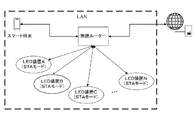
図2は、本願開示の様々な態様にしたがった照明装置を用いる、ネットワーク異常を修正するための自己修復システムの1例を示している。前記自己修復システムの例は、無線ルーター、無線通信性能を備えるスマート端末、及び複数の照明装置を含むことができる。各照明装置は、無線AP機能を備えるWI−FIモジュールを含むことができる。特定の態様において、前記照明装置はLED(発光ダイオード)照明装置でもよい。前記スマート端末は、例えば、スマートフォン、ラップトップ・コンピュータ、タブレット・コンピュータ、PDA、スマート・ウォッチ、などのような無線通信性能を有する如何なるスマート装置であってもよい。1つの態様において、前記スマート端末はスマートフォンでもよい。 FIG. 2 illustrates an example of a self-healing system for correcting network anomalies using lighting devices according to various aspects of the present disclosure. Examples of the self-healing system may include a wireless router, a smart terminal with wireless communication performance, and a plurality of lighting devices. Each lighting device may include a WI-FI module with a wireless AP function. In a particular embodiment, the lighting device may be an LED (light emitting diode) lighting device. The smart terminal may be any smart device having wireless communication performance such as a smart phone, a laptop computer, a tablet computer, a PDA, a smart watch, and the like. In one aspect, the smart terminal may be a smartphone.
1例の態様において、複数のLED照明装置は1つの(元の)無線ルーターにそれぞれ接続することができる。スマートフォンは、前記無線ルーターに無線で接続し、前記無線ルーターを介して前記LED照明装置を制御することができる。前記無線ルーターが異常により接続できないとき、全ての前記LED照明装置の中で1つの新しいLED照明装置を、自己修復ネットワーキング規則にしたがって、新しい照明装置ルーターとして選択することができる。前記スマートフォン及び前記その他の非選択のLED照明装置(前記選択されたLED照明装置を除く)は、それぞれ無線で前記新しい照明装置ルーター(すなわち、前記選択されたLED照明装置)に接続することができる。 In one example embodiment, multiple LED lighting devices can each be connected to one (original) wireless router. The smartphone can wirelessly connect to the wireless router and control the LED lighting device via the wireless router. When the wireless router cannot be connected due to an anomaly, one new LED lighting device among all the LED lighting devices can be selected as a new lighting device router according to self-healing networking rules. The smartphone and the other non-selected LED lighting devices (except the selected LED lighting device) can each be wirelessly connected to the new lighting device router (ie, the selected LED lighting device). .
開示されるように、様々な自己修復ネットワーキング規則を本願発明で用いることができる。説明のために、前記自己修復ネットワーキング規則は、前記LED照明装置のMACアドレスの値と比較して、前記ネットワーク自己修復システムのために主要に記載される。この例において、最小のMACアドレスを有するLED照明装置は、前記新しい照明装置ルーターに選択される。前記ネットワーキング・プロセスは、次の例のプロセスを含むことができる。 As disclosed, various self-healing networking rules can be used in the present invention. For illustration purposes, the self-healing networking rules are primarily described for the network self-healing system compared to the MAC address value of the LED lighting device. In this example, the LED lighting device with the lowest MAC address is selected for the new lighting device router. The networking process may include the following example process.
前記無線ルーターが正常に操作するとき、前記無線ルーターは、LED照明装置A、LED照明装置B、LED照明装置C、...及びLED照明装置Nを含む、複数のLED照明装置に無線で接続する。これらのLED照明装置は、AP機能を含むことができる。これらのLED照明装置は、オフ又は非起動状態のAP機能を有することができる。また、これらのLED照明装置は、STA(station)ワーキング・モードにあることもできる。前記スマート端末は、前記無線ルーターに無線で接続することにより、前記LED照明装置を制御することができる。その間に、前記無線ルーターは、インターネット又はクラウド・サーバーに接続して、遠隔制御信号を受信し、前記LED照明装置を制御することができる。また、前記スマート端末は、前記無線ルーターに無線で接続することにより、インターネットにアクセスすることもできる。 When the wireless router operates normally, the wireless router includes LED lighting device A, LED lighting device B, LED lighting device C,. . . And a plurality of LED lighting devices including the LED lighting device N are wirelessly connected. These LED lighting devices can include an AP function. These LED lighting devices may have an AP function that is off or not activated. These LED lighting devices can also be in a STA (station) working mode. The smart terminal can control the LED lighting device by wirelessly connecting to the wireless router. Meanwhile, the wireless router can connect to the Internet or a cloud server to receive a remote control signal and control the LED lighting device. In addition, the smart terminal can access the Internet by wirelessly connecting to the wireless router.
前記無線ルーターが前記ネットワークから消え、適切に接続できないとき、全ての前記LED照明装置は、自己修復ネットワーキング・モードにスイッチを入れることができる。すなわち、全ての前記LED照明装置は前記AP機能を起動することができる。すべての前記LED照明装置は、そのSSIDを呼ばれるとき統一された名前接頭辞(name prefix)を有するように構成することができる。例えば、前記名前接頭辞は、「Sengled」のような統一されたユーザー名又はベンダー名であり得る。前記SSIDは、前記MACアドレスの最後の4つの文字の後に接尾辞名をもつことができる。例えば、MACアドレスの最後の4つの文字が、AAAA、AAAB、及びAAACであるとき、前記SSIDはSengledAAAA、SengledAAAB、及びSengledAAABと呼ばれることができる。 When the wireless router disappears from the network and cannot be properly connected, all the LED lighting devices can be switched into a self-healing networking mode. That is, all the LED lighting devices can activate the AP function. All the LED lighting devices can be configured to have a unified name prefix when called for their SSID. For example, the name prefix may be a unified user name or vendor name such as “Sengled”. The SSID may have a suffix name after the last four characters of the MAC address. For example, when the last four characters of the MAC address are AAAA, AAAB, and AAAC, the SSID can be called SengledAAAA, SengledAAAB, and SengledAAAB.
図3に示されるように、最小のMACアドレスを有するLED照明装置Aは前記照明装置ルーター又は新しいアクセス・ポイントに選択することができる。前記LED照明装置Aは前記APの起動状態又はオン状態に維持することができる。前記その他の非選択LED照明装置は、予め設定される公開されているパスワードを用いて、STAワーキング・モードにスイッチを入れることができる。前記その他のLED照明装置はSengledAAAA(例えば、LED照明装置A)にアクセスすることができる。前記スマート端末は、制御LED照明装置A自身を含み、前記LED照明装置Aにより提供されるネットワークにおける全ての前記LED照明装置を制御することができる。 As shown in FIG. 3, the LED lighting device A with the lowest MAC address can be selected as the lighting device router or a new access point. The LED lighting device A can be maintained in the activated state or the on state of the AP. The other non-selected LED lighting devices can be switched to the STA working mode using a preset public password. The other LED lighting device can access a Sengled AAAA (eg, LED lighting device A). The smart terminal includes the control LED lighting device A itself and can control all the LED lighting devices in the network provided by the LED lighting device A.
前記元の無線ルーターが使用されるとき、前記元の無線ルーターは、前記LED照明装置が遠隔制御できるように、インターネットに接続することができる。また、前記スマートフォンは、前記元の無線ルーターを介してインターネットにアクセスすることができる。前記元の無線ルーターが接続できないとき、前記LED照明装置は自己修復ネットワーキング・タスクを実行して、新しい照明装置ルーター又は新しいアクセス・ポイントを提供し、新しいローカルエリア・ネットワーク(LAN)を構築することができる。前記スマート端末は、前記新しい照明装置ルーター又はアクセス・ポイントに接続して、前記LAN内の前記LED照明装置を制御することができる。前記選択されたLED照明装置、すなわち、前記新しい照明装置ルーター又はアクセス・ポイントも異常により接続できないとき、全ての前記残りのLED照明装置は、そのAP機能を起動して、前記自己修復ネットワーキング・プロセスを繰り返し、最小のMACアドレスを有するLED照明装置を選択してもう1つの新しい照明装置ルーター又はアクセス・ポイントを提供して、前記LED照明装置を制御するため安定なネットワークを確立することができる。 When the original wireless router is used, the original wireless router can be connected to the Internet so that the LED lighting device can be remotely controlled. Further, the smartphone can access the Internet via the original wireless router. When the original wireless router cannot connect, the LED lighting device performs a self-healing networking task to provide a new lighting device router or a new access point and build a new local area network (LAN) Can do. The smart terminal can connect to the new lighting device router or access point to control the LED lighting devices in the LAN. When the selected LED lighting device, i.e., the new lighting device router or access point, cannot be connected due to an abnormality, all the remaining LED lighting devices will activate their AP function to enable the self-healing networking process. To select the LED lighting device with the lowest MAC address and provide another new lighting device router or access point to establish a stable network to control the LED lighting device.
本願開示にしたがった、いくつかの態様において、ネットワーク自己修復機能は、ネットワーク状態をユーザーに示すために前記LED照明設定に取り込むことができる。例えば、前記元のWI−FIルーターが接続できないとき、前記WI−FIルーターを取り込んだLED照明装置は、光を点滅し又は異なる色に変化させて、前記WI−FIルーターが消えたことを示すことができる。また、新しい照明装置が選択されるとき、前記照明装置も、前記LED照明(全て又はいくつかの照明装置の)を異なる色又は点滅に設定して、前記新しい照明装置が前記ネットワークのルーターとして機能することを示すことができる。 In some aspects according to the present disclosure, a network self-healing function can be incorporated into the LED lighting settings to indicate network status to the user. For example, when the original WI-FI router cannot be connected, the LED lighting device incorporating the WI-FI router blinks light or changes to a different color to indicate that the WI-FI router has disappeared. be able to. Also, when a new lighting device is selected, the lighting device also sets the LED lighting (for all or some lighting devices) to a different color or blinking so that the new lighting device functions as a router for the network Can show that
また、様々なネットワーク自己修復機能に関連する照明調節もスマートフォンを介してユーザーによりカスタマイズすることができる。例えば、ユーザーは、前記照明装置に接続されるスマートフォンの制御プログラムを用いて、前記WI−FIルーターを備える元の照明装置がもう接続できないとき、全ての前記LED照明装置がオレンジ色の光を短時間(例えば、5秒間)発するように設定することができる。新しい照明装置が前記新しいルーターとして働くように選択されるとき、前記ユーザーは、制御プログラムを用いて、全ての前記LED照明装置が緑色の光を短時間(例えば、5秒間)発するように設定することができる。 Also, lighting adjustments related to various network self-healing functions can be customized by the user via the smartphone. For example, when a user can no longer connect an original lighting device equipped with the WI-FI router using a control program for a smartphone connected to the lighting device, all the LED lighting devices shorten orange light. It can be set to emit time (eg, 5 seconds). When a new lighting device is selected to act as the new router, the user uses a control program to set all the LED lighting devices to emit green light for a short time (eg, 5 seconds) be able to.
本願開示のその他の態様は、本願開示の発明の明細書及び実施を考慮すれば、当業者に明らかであろう。本願の明細書及び実施は単なる例示であり、本願発明の真の範囲及び神髄は特許請求の範囲で示される、として企図されるものである。 Other aspects of the present disclosure will be apparent to those skilled in the art from consideration of the specification and practice of the invention disclosed herein. It is intended that the specification and practice of this application be exemplary only, with the true scope and spirit of the present invention being set forth in the claims.
如何なる請求項及び/又は明細書の範囲の限定なしに、本願開示の態様の産業上の利用可能性及び特定の有利な効果を、実例を挙げて説明する。本願開示の態様の解決手段の様々な変更、修飾、又は等価物は当業者に明らかであり得、本願開示に含むことができる。 Without limitation of the scope of any claims and / or the specification, the industrial applicability and certain advantageous effects of the aspects disclosed herein will be described by way of illustration. Various changes, modifications, or equivalents of the solutions of the aspects of the present disclosure may be apparent to those skilled in the art and can be included in the present disclosure.
本願開示は、照明装置を用いるネットワーク異常のための自己修復方法及びシステムを提供する。前記照明装置は、無線ルーター異常時又は接続ラインに問題があるとき、自己修復ネットワークを構築して前記照明装置の制御が失われることを防ぐことができる。前記元の無線ルーターが接続できないことを確認後、各照明装置は前記AP機能にスイッチを入れることができる。1つの照明装置を、自己修復ネットワーキング規則にしたがって新しい照明装置ルーター(又は新しいアクセス・ポイント)に選択することができる。照明装置が選択されたとき、前記その他の非選択の照明装置(前記選択された照明装置を除く)は、そのAP機能をオフにして、前記新しい照明装置ルーター又はアクセス・ポイントにそれぞれ無線で接続することができる。前記選択された照明装置は、新しいネットワークを構築する先端として働くことができる。 The present disclosure provides a self-healing method and system for network anomalies using lighting devices. The lighting device can establish a self-healing network to prevent loss of control of the lighting device when a wireless router malfunctions or there is a problem with a connection line. After confirming that the original wireless router cannot be connected, each lighting device can switch on the AP function. One lighting device can be selected for a new lighting device router (or new access point) according to self-healing networking rules. When a lighting device is selected, the other non-selected lighting devices (except the selected lighting device) wirelessly connect to the new lighting device router or access point, respectively, with their AP function turned off. can do. The selected lighting device can serve as a tip for building a new network.
自己修復ネットワーキング方法は、融通性をもってネットワーク異常を処理し、ネットワークの安定性を維持し、効果的でタイムリーな様式で照明制御を確保することができ、これにより信頼性があり快適な家庭生活環境を提供する。 Self-healing networking methods can handle network anomalies with flexibility, maintain network stability, and ensure lighting control in an effective and timely manner, thereby providing a reliable and comfortable home life Provide an environment.
Claims (20)
各照明装置が無線アクセス・ポイント(AP)機能を備えるWI−FIモジュールを含み、ここで当該複数の照明装置が無線で無線ルーターに接続される、複数の照明装置を提供すること、
前記複数の照明装置により、前記無線ルーターのサービス・セット識別子(SSID)をスキャンして、前記無線ルーターが接続できず、自己修復ネットワーキング・モードにスイッチを入れることを確認すること、
前記複数の照明装置から1つの照明装置を選択する自己修復ネットワーキング規則にしたがって、各照明装置の無線AP機能を起動し、前記選択された照明装置を第一照明装置ルーターとして用いること、及び
前記複数の照明装置のうち残っているその他の各非選択の照明装置の無線AP機能を非起動にして、前記その他の非選択の照明装置を前記第一照明装置ルーターにそれぞれ無線で接続すること、
を含む、方法。 A network self-healing method using a lighting device,
Providing a plurality of lighting devices, each lighting device including a WI-FI module with wireless access point (AP) functionality, wherein the plurality of lighting devices are wirelessly connected to a wireless router;
Scanning the service set identifier (SSID) of the wireless router with the plurality of lighting devices to confirm that the wireless router cannot connect and switches to self-healing networking mode;
Activating a wireless AP function of each lighting device according to a self-healing networking rule for selecting one lighting device from the plurality of lighting devices, and using the selected lighting device as a first lighting device router; and Deactivating the wireless AP function of each remaining non-selected lighting device among the other lighting devices, and wirelessly connecting the other non-selected lighting devices to the first lighting device router,
Including the method.
前記第一照明装置ルーターにより前記無線ルーターをスキャンし、前記無線ルーターへの再接続を試みること、
前記第一照明装置ルーターが前記無線ルーターにうまく接続されるとき、前記複数の照明装置にうち残されたその他の非選択の照明装置に告知すること、
前記第一照明装置ルーターの無線AP機能をスイッチ・オフすること、及び
前記第一照明装置ルーターを、前記その他の非選択の照明装置とともに、前記無線ルーターに再接続すること、
を含む、請求項1に記載の方法。 After the step of wirelessly connecting the unselected lighting device to the first lighting device router,
Scanning the wireless router with the first lighting device router and attempting to reconnect to the wireless router;
When the first lighting device router is successfully connected to the wireless router, notifying other non-selected lighting devices left in the plurality of lighting devices;
Switching off the wireless AP function of the first lighting device router; and reconnecting the first lighting device router to the wireless router along with the other non-selected lighting devices;
The method of claim 1 comprising:
前記無線ルーターのSSIDがうまくスキャンされるとき、前記第一照明装置ルーターが前記無線ルーターに接続を試みる、
請求項2に記載の方法。 The first lighting device router scans the wireless router at preset time intervals; and
When the SSID of the wireless router is successfully scanned, the first lighting device router attempts to connect to the wireless router;
The method of claim 2.
前記第一照明装置ルーターが接続できないとき、前記複数の照明装置から、自己修復ネットワーキング用の第二照明装置としてもう1つの照明装置を再選択する方法を繰り返すこと、
を含む、請求項2に記載の方法。 further,
Repeating the method of reselecting another lighting device as a second lighting device for self-healing networking from the plurality of lighting devices when the first lighting device router cannot be connected;
The method of claim 2 comprising:
請求項1に記載の方法。 In the step of scanning by the plurality of lighting devices, the SSID of the wireless router is successfully detected after the SSID of the wireless router is continuously scanned by the plurality of lighting devices during a first preset time interval. When not scanned, it is confirmed that the wireless router cannot connect and the self-healing networking mode is switched on,
The method of claim 1.
請求項1に記載の方法。 In the step of scanning by the plurality of lighting devices, after the SSID of the wireless router is continuously scanned, the SSID of the wireless router is successfully scanned, but the wireless router is in a second preset time interval. When the wireless router cannot be connected after successive attempts during, the self-healing networking mode is switched on.
The method of claim 1.
前記複数の照明装置から、カスタマイズされた予め設定されるルーティング表にしたがって、前記第一照明装置ルーターとして連続的に前記1つの照明装置を選択すること、
を含む、請求項1に記載の方法。 The self-healing networking rules are
Continuously selecting the one lighting device as the first lighting device router from the plurality of lighting devices according to a customized preset routing table;
The method of claim 1 comprising:
前記自己修復ネットワーキング規則が、前記複数の照明装置から、前記第一照明装置ルーターとして、最大又は最小のMACアドレスを有する前記1つの照明装置を選択することを含む、
請求項1に記載の方法。 Each lighting device corresponds to a media access control (MAC) address, and the self-healing networking rule has a maximum or minimum MAC address as the first lighting device router from the plurality of lighting devices. Including selecting one lighting device,
The method of claim 1.
前記最大又は最小のMACアドレスが、前記複数の照明装置のSSIDの値を比較することにより決定される、
請求項9に記載の方法。 The SSID of each lighting device includes a MAC address name, and the maximum or minimum MAC address is determined by comparing SSID values of the plurality of lighting devices;
The method of claim 9.
請求項1に記載の方法。 The self-healing networking rule adopts a self-routing protocol for self-networking and modifies a commonly used routing protocol to allow the lighting devices to connect to the self-networking;
The method of claim 1.
各照明装置から集められたネットワーク資源状況にしたがって、ユーザーのQoS要求を最も満足させそうな1つの照明装置が前記第一照明装置ルーターとして選択される、
請求項1に記載の方法。 The self-healing networking rule includes a self-networking routing protocol based on quality of service (QoS) and is most likely to satisfy the user's QoS requirements according to the network resource status collected from each lighting device. One lighting device is selected as the first lighting device router;
The method of claim 1.
定期的にルーティング情報を放送することによりルーティング表を維持する代わりに、ネットワーク消費の効果的な低減が必要なときのみに、ルーティングを確立するルーティング要求を送信する、
請求項1に記載の方法。 The self-healing networking rules include on-demand routing rules, and routing is only done when effective reduction of network consumption is required instead of maintaining routing tables by broadcasting routing information periodically. Send routing request to establish,
The method of claim 1.
前記無線ルーターが接続できないとき、前記スマート端末が前記その他の非選択の照明装置とともに前記第一照明装置ルーターに接続される、
請求項2に記載の方法。 A smart terminal is wirelessly connected to the wireless router to control the plurality of lighting devices, and when the wireless router is unable to connect, the smart terminal is connected to the first lighting device router along with the other non-selected lighting devices. Connected to the
The method of claim 2.
前記スマート端末を前記無線ルーターに無線で再接続することを含む、
請求項14に記載の方法。 Reconnecting the first lighting device router to the wireless router along with the other non-selected lighting device routers;
Wirelessly reconnecting the smart terminal to the wireless router;
The method according to claim 14.
請求項3に記載の方法。 The preset time interval is 20 to 40 seconds;
The method of claim 3.
前記複数の照明装置に無線で接続される無線ルーター、
を含むネットワーク自己修復システムであって、ここで、
前記無線ルーターが接続されないとき、前記複数の照明装置が自己修復ネットワーキング・モードにスイッチを入れて各照明装置の前記無線AP機能を起動し、
自己修復ネットワーキング規則にしたがって、前記複数の照明装置から1つの照明装置が選択され、当該選択された照明装置が照明装置ルーターとして用いられ、及び
その他の非選択の照明装置のそれぞれが、前記無線AP機能を非起動にし、それぞれ前記照明装置ルーターに無線で接続する、
システム。 A plurality of lighting devices each including a WI-FI module having a wireless AP function, and a wireless router wirelessly connected to the plurality of lighting devices;
A network self-healing system comprising:
When the wireless router is not connected, the plurality of lighting devices switch on a self-healing networking mode to activate the wireless AP function of each lighting device;
A lighting device is selected from the plurality of lighting devices according to a self-healing networking rule, the selected lighting device is used as a lighting device router, and each of the other non-selected lighting devices is connected to the wireless AP. Deactivate the function and connect to the lighting device router wirelessly,
system.
前記スマート端末が前記無線ルーターに無線で接続し、前記複数の照明装置を制御し、及び
前記無線ルーターが接続できないとき、前記スマート端末が前記照明装置ルーターに無線で接続する、
請求項17に記載のシステム。 In addition, including a smart terminal having wireless communication performance,
The smart terminal wirelessly connects to the wireless router, controls the plurality of lighting devices, and when the wireless router cannot connect, the smart terminal wirelessly connects to the lighting device router;
The system of claim 17.
The system according to claim 18, wherein the smart terminal is a smart phone, a laptop computer, a tablet computer, a PDA (personal information terminal) or a smart watch.
Applications Claiming Priority (3)
| Application Number | Priority Date | Filing Date | Title |
|---|---|---|---|
| CN201410469731.0 | 2014-09-15 | ||
| CN201410469731.0A CN104301917A (en) | 2014-09-15 | 2014-09-15 | Network anomaly self-healing method and system based on illumination devices |
| PCT/CN2015/077070 WO2016041350A1 (en) | 2014-09-15 | 2015-04-21 | Network self-healing method and system using lightingdevices |
Publications (2)
| Publication Number | Publication Date |
|---|---|
| JP2017509174A true JP2017509174A (en) | 2017-03-30 |
| JP6225264B2 JP6225264B2 (en) | 2017-11-01 |
Family
ID=52321437
Family Applications (1)
| Application Number | Title | Priority Date | Filing Date |
|---|---|---|---|
| JP2016538634A Expired - Fee Related JP6225264B2 (en) | 2014-09-15 | 2015-04-21 | Network self-healing method and system using lighting device |
Country Status (6)
| Country | Link |
|---|---|
| US (1) | US9955369B2 (en) |
| EP (1) | EP3135073B1 (en) |
| JP (1) | JP6225264B2 (en) |
| KR (1) | KR101822778B1 (en) |
| CN (1) | CN104301917A (en) |
| WO (1) | WO2016041350A1 (en) |
Families Citing this family (13)
| Publication number | Priority date | Publication date | Assignee | Title |
|---|---|---|---|---|
| CN104039045A (en) * | 2014-06-04 | 2014-09-10 | 生迪光电科技股份有限公司 | LED (Light Emitting Diode) illuminating device based remote monitoring system and method |
| CN104301917A (en) * | 2014-09-15 | 2015-01-21 | 浙江生辉照明有限公司 | Network anomaly self-healing method and system based on illumination devices |
| CN105228224A (en) * | 2015-10-29 | 2016-01-06 | 小米科技有限责任公司 | The cut-in method of wireless network and device |
| CN107241838B (en) * | 2016-03-29 | 2019-07-02 | 北京小米移动软件有限公司 | Single firewire switch Working mode switching method and device |
| CN106878969B (en) * | 2017-01-04 | 2020-04-14 | 普联技术有限公司 | Wireless networking method, wireless networking equipment and wireless networking system |
| CN107018544B (en) * | 2017-04-10 | 2019-12-10 | 北京德威特电气科技股份有限公司 | Access method and device of wireless network |
| CN107071863A (en) * | 2017-05-02 | 2017-08-18 | 青岛海尔空调器有限总公司 | A kind of household electrical appliances match somebody with somebody network method, household electrical appliances and user terminal |
| WO2018237395A1 (en) * | 2017-06-23 | 2018-12-27 | Lunera Lighting Inc. | Checking wi-fi coverage using led lamps |
| CN107800777A (en) * | 2017-09-29 | 2018-03-13 | 珠海格力电器股份有限公司 | Long-distance monitoring method, device, storage medium and equipment |
| CN109361554A (en) * | 2018-11-30 | 2019-02-19 | 深圳市普威技术有限公司 | The method and apparatus of the customized management page and default configuration |
| KR20200102132A (en) | 2019-02-21 | 2020-08-31 | 삼성전자주식회사 | Electronic apparatus and method for controlling the electronic apparatus |
| CN111294781B (en) * | 2020-02-13 | 2021-08-10 | 西安交通大学 | Mobile self-organizing network recovery method based on WI-FI DIRECT |
| CN112333062A (en) * | 2020-11-03 | 2021-02-05 | 深圳Tcl新技术有限公司 | Control method and control device for household equipment and computer readable storage medium |
Citations (3)
| Publication number | Priority date | Publication date | Assignee | Title |
|---|---|---|---|---|
| WO2011158512A1 (en) * | 2010-06-18 | 2011-12-22 | パナソニック株式会社 | Communication terminal device and communication method |
| JP2012199992A (en) * | 2007-03-28 | 2012-10-18 | Intel Corp | Device and method of connectivity recovery in wireless network |
| WO2013126731A2 (en) * | 2012-02-24 | 2013-08-29 | Qualcomm Incorporated | Sensor based configuration and control of network devices |
Family Cites Families (26)
| Publication number | Priority date | Publication date | Assignee | Title |
|---|---|---|---|---|
| US7813326B1 (en) * | 2005-05-27 | 2010-10-12 | Bluetronix Inc. | Swarm location service for mobile ad hoc network communications |
| TWI330710B (en) | 2006-05-16 | 2010-09-21 | Elitegroup Computer Sys Co Ltd | Online consultation system, consultation apparatus and consultation method |
| US8035320B2 (en) * | 2007-04-20 | 2011-10-11 | Sibert W Olin | Illumination control network |
| JP5137746B2 (en) * | 2008-08-28 | 2013-02-06 | キヤノン株式会社 | COMMUNICATION DEVICE, COMMUNICATION DEVICE CONTROL METHOD, PROGRAM |
| EP2309805B1 (en) * | 2009-10-11 | 2012-10-24 | Research In Motion Limited | Handling wrong WEP key and related battery drain and communication exchange failures |
| JP5093255B2 (en) * | 2010-01-29 | 2012-12-12 | ブラザー工業株式会社 | Developer supply device |
| US8411608B2 (en) * | 2010-02-26 | 2013-04-02 | Microsoft Corporation | Efficient and reliable multicast over a Wi-Fi network |
| US10564613B2 (en) * | 2010-11-19 | 2020-02-18 | Hubbell Incorporated | Control system and method for managing wireless and wired components |
| US8599759B2 (en) * | 2011-04-29 | 2013-12-03 | Cooper Technologies Company | Multi-path radio transmission input/output devices, network, systems and methods with on demand, prioritized routing protocol |
| EP2519071B1 (en) * | 2011-04-30 | 2019-01-30 | Samsung Electronics Co., Ltd. | Method and system for delegating group ownership in a wi-fi peer to peer network |
| CN102333023B (en) * | 2011-09-30 | 2014-01-01 | 福建星网锐捷网络有限公司 | Communication method and equipment in multilink transparent internet |
| KR101844211B1 (en) * | 2011-12-28 | 2018-05-15 | 삼성전자주식회사 | Network system of home appliance and network set up method the same |
| US9049616B2 (en) * | 2012-03-29 | 2015-06-02 | Broadcom Corporation | Session recovery after network coordinator or AP restart for single user, multiple user, multiple access, and/or MIMO wireless communications |
| CN102752916B (en) * | 2012-06-12 | 2015-07-08 | 浙江生辉照明有限公司 | Light-emitting diode (LED) lamp and LED lighting system |
| CN102858060A (en) * | 2012-08-16 | 2013-01-02 | 浙江生辉照明有限公司 | Light emitting diode (LED) lamp and LED illumination network system |
| US9730108B2 (en) * | 2012-12-14 | 2017-08-08 | Plantronics, Inc. | Network architecture using Wi-Fi devices |
| US9413171B2 (en) * | 2012-12-21 | 2016-08-09 | Lutron Electronics Co., Inc. | Network access coordination of load control devices |
| CN103369790A (en) * | 2013-06-20 | 2013-10-23 | 浙江生辉照明有限公司 | LED (Light Emitting Diode) illuminating device and illumination control system |
| CN103313488B (en) * | 2013-07-03 | 2016-08-17 | 北京半导体照明科技促进中心 | Illumination control method and system and wifi controller and lighting apparatus |
| CN103442410A (en) * | 2013-08-27 | 2013-12-11 | 上海汉枫电子科技有限公司 | Network breakdown re-access method based on internet of things embedded Wi-Fi module |
| CN103533670A (en) * | 2013-10-15 | 2014-01-22 | 深圳市江波龙电子有限公司 | Method and device for connecting wireless network equipment, and wireless network system |
| KR20150060275A (en) * | 2013-11-26 | 2015-06-03 | 삼성전자주식회사 | Electronic device and method for providing data service in electronic device |
| CN103648181B (en) * | 2013-12-24 | 2017-01-11 | 广州爱的信息科技有限公司 | Wireless network connection method for wireless network audio equipment |
| CN103986630B (en) | 2014-04-30 | 2018-11-30 | 生迪光电科技股份有限公司 | Radio Network System and intelligent device management method based on LED light device |
| US9992733B2 (en) * | 2014-05-30 | 2018-06-05 | Apple Inc. | Device and method for opportunistic roaming |
| CN104301917A (en) * | 2014-09-15 | 2015-01-21 | 浙江生辉照明有限公司 | Network anomaly self-healing method and system based on illumination devices |
-
2014
- 2014-09-15 CN CN201410469731.0A patent/CN104301917A/en active Pending
-
2015
- 2015-04-21 EP EP15842720.3A patent/EP3135073B1/en active Active
- 2015-04-21 WO PCT/CN2015/077070 patent/WO2016041350A1/en active Application Filing
- 2015-04-21 JP JP2016538634A patent/JP6225264B2/en not_active Expired - Fee Related
- 2015-04-21 KR KR1020167025116A patent/KR101822778B1/en active IP Right Grant
- 2015-04-21 US US15/025,493 patent/US9955369B2/en active Active
Patent Citations (4)
| Publication number | Priority date | Publication date | Assignee | Title |
|---|---|---|---|---|
| JP2012199992A (en) * | 2007-03-28 | 2012-10-18 | Intel Corp | Device and method of connectivity recovery in wireless network |
| WO2011158512A1 (en) * | 2010-06-18 | 2011-12-22 | パナソニック株式会社 | Communication terminal device and communication method |
| WO2013126731A2 (en) * | 2012-02-24 | 2013-08-29 | Qualcomm Incorporated | Sensor based configuration and control of network devices |
| JP2015515048A (en) * | 2012-02-24 | 2015-05-21 | クアルコム,インコーポレイテッド | Sensor-based configuration and control of network devices |
Also Published As
| Publication number | Publication date |
|---|---|
| EP3135073A1 (en) | 2017-03-01 |
| WO2016041350A1 (en) | 2016-03-24 |
| CN104301917A (en) | 2015-01-21 |
| JP6225264B2 (en) | 2017-11-01 |
| KR101822778B1 (en) | 2018-03-08 |
| KR20160113726A (en) | 2016-09-30 |
| US20160219447A1 (en) | 2016-07-28 |
| EP3135073A4 (en) | 2017-10-18 |
| EP3135073B1 (en) | 2019-02-27 |
| US9955369B2 (en) | 2018-04-24 |
Similar Documents
| Publication | Publication Date | Title |
|---|---|---|
| JP6225264B2 (en) | Network self-healing method and system using lighting device | |
| US11109185B2 (en) | Mesh network and mesh device and network distribution method thereof | |
| EP2652905B1 (en) | Increased communication opportunities with low-contact nodes in a computer network | |
| US9906935B2 (en) | Bluetooth low energy beacon device and advertising method | |
| US10104040B2 (en) | Wireless local area network WLAN user roaming method, apparatus, and system | |
| CN105392181B (en) | A kind of networking method of smart machine, apparatus and system | |
| US10666356B2 (en) | Visible light-based communication method, related device, and related system | |
| KR20120052092A (en) | Method for tethering network, method for connecting network and wirelessly communication system thereof | |
| US9215642B2 (en) | Service packet forwarding and processing method and system, and access point AP | |
| CN105392185B (en) | A kind of networking method of smart machine, apparatus and system | |
| CN105246027A (en) | D2D relay resource configuration method, device and system | |
| CN105871995A (en) | Method for controlling intelligent device by router and the router | |
| JP6290251B2 (en) | Delegated channel switching for mesh networks | |
| JP2009141535A (en) | Wireless lan system and its connection method | |
| US20150117180A1 (en) | System, apparatus and method for reducing failover time through redundancy using virtual access points | |
| CN107925940B (en) | Communication system, communication device and method for reconnecting communication system | |
| CN111565474B (en) | Method and system for establishing communication connection between AP (access point) equipment and target terminal based on Mesh network | |
| KR20150045639A (en) | Method and its apparatus for selectioning network in beamforming system | |
| CN107534917A (en) | Switching method, main equipment, slave unit and system in a kind of master-slave type network | |
| EP3340687B1 (en) | Method for connecting communication device, and communication device | |
| CN104486252B (en) | A kind of method and device of thin-client access standard client | |
| CN108174434A (en) | A kind of method, terminal and smart machine for automatically switching communication mode | |
| JP6651733B2 (en) | Audio system, audio equipment, and audio equipment management method | |
| JP2011061282A (en) | Terminal device and radio communication system and method | |
| JP2007274135A (en) | Network device and simultaneous calling method |
Legal Events
| Date | Code | Title | Description |
|---|---|---|---|
| A131 | Notification of reasons for refusal |
Free format text: JAPANESE INTERMEDIATE CODE: A131 Effective date: 20170110 |
|
| A521 | Request for written amendment filed |
Free format text: JAPANESE INTERMEDIATE CODE: A523 Effective date: 20170410 |
|
| A131 | Notification of reasons for refusal |
Free format text: JAPANESE INTERMEDIATE CODE: A131 Effective date: 20170606 |
|
| A601 | Written request for extension of time |
Free format text: JAPANESE INTERMEDIATE CODE: A601 Effective date: 20170901 |
|
| A521 | Request for written amendment filed |
Free format text: JAPANESE INTERMEDIATE CODE: A523 Effective date: 20170926 |
|
| TRDD | Decision of grant or rejection written | ||
| A01 | Written decision to grant a patent or to grant a registration (utility model) |
Free format text: JAPANESE INTERMEDIATE CODE: A01 Effective date: 20171003 |
|
| A61 | First payment of annual fees (during grant procedure) |
Free format text: JAPANESE INTERMEDIATE CODE: A61 Effective date: 20171006 |
|
| R150 | Certificate of patent or registration of utility model |
Ref document number: 6225264 Country of ref document: JP Free format text: JAPANESE INTERMEDIATE CODE: R150 |
|
| LAPS | Cancellation because of no payment of annual fees |