JP2017508122A - refrigerator - Google Patents
refrigerator Download PDFInfo
- Publication number
- JP2017508122A JP2017508122A JP2016547910A JP2016547910A JP2017508122A JP 2017508122 A JP2017508122 A JP 2017508122A JP 2016547910 A JP2016547910 A JP 2016547910A JP 2016547910 A JP2016547910 A JP 2016547910A JP 2017508122 A JP2017508122 A JP 2017508122A
- Authority
- JP
- Japan
- Prior art keywords
- door
- refrigerator
- guide
- guide rail
- sub
- Prior art date
- Legal status (The legal status is an assumption and is not a legal conclusion. Google has not performed a legal analysis and makes no representation as to the accuracy of the status listed.)
- Granted
Links
- 230000005540 biological transmission Effects 0.000 claims description 92
- 239000000758 substrate Substances 0.000 claims description 15
- 230000033001 locomotion Effects 0.000 claims description 8
- 238000000034 method Methods 0.000 claims description 5
- 239000011521 glass Substances 0.000 claims description 4
- 238000002054 transplantation Methods 0.000 claims 1
- 238000001816 cooling Methods 0.000 abstract description 9
- 235000013305 food Nutrition 0.000 abstract 1
- 238000007710 freezing Methods 0.000 abstract 1
- 230000008014 freezing Effects 0.000 abstract 1
- 238000005057 refrigeration Methods 0.000 abstract 1
- 238000010586 diagram Methods 0.000 description 7
- 238000007789 sealing Methods 0.000 description 6
- 238000003860 storage Methods 0.000 description 5
- 229920002725 thermoplastic elastomer Polymers 0.000 description 5
- 239000000463 material Substances 0.000 description 4
- 229920002943 EPDM rubber Polymers 0.000 description 3
- 238000004519 manufacturing process Methods 0.000 description 3
- 238000005265 energy consumption Methods 0.000 description 2
- 239000004677 Nylon Substances 0.000 description 1
- 229910000831 Steel Inorganic materials 0.000 description 1
- 238000004891 communication Methods 0.000 description 1
- 230000008878 coupling Effects 0.000 description 1
- 238000010168 coupling process Methods 0.000 description 1
- 238000005859 coupling reaction Methods 0.000 description 1
- 229920001971 elastomer Polymers 0.000 description 1
- 230000002452 interceptive effect Effects 0.000 description 1
- 229920001778 nylon Polymers 0.000 description 1
- 238000005096 rolling process Methods 0.000 description 1
- 239000010959 steel Substances 0.000 description 1
- 238000004804 winding Methods 0.000 description 1
Images


Classifications
-
- F—MECHANICAL ENGINEERING; LIGHTING; HEATING; WEAPONS; BLASTING
- F25—REFRIGERATION OR COOLING; COMBINED HEATING AND REFRIGERATION SYSTEMS; HEAT PUMP SYSTEMS; MANUFACTURE OR STORAGE OF ICE; LIQUEFACTION SOLIDIFICATION OF GASES
- F25D—REFRIGERATORS; COLD ROOMS; ICE-BOXES; COOLING OR FREEZING APPARATUS NOT OTHERWISE PROVIDED FOR
- F25D23/00—General constructional features
- F25D23/02—Doors; Covers
- F25D23/021—Sliding doors
-
- E—FIXED CONSTRUCTIONS
- E05—LOCKS; KEYS; WINDOW OR DOOR FITTINGS; SAFES
- E05D—HINGES OR SUSPENSION DEVICES FOR DOORS, WINDOWS OR WINGS
- E05D15/00—Suspension arrangements for wings
- E05D15/16—Suspension arrangements for wings for wings sliding vertically more or less in their own plane
- E05D15/165—Details, e.g. sliding or rolling guides
-
- E—FIXED CONSTRUCTIONS
- E05—LOCKS; KEYS; WINDOW OR DOOR FITTINGS; SAFES
- E05F—DEVICES FOR MOVING WINGS INTO OPEN OR CLOSED POSITION; CHECKS FOR WINGS; WING FITTINGS NOT OTHERWISE PROVIDED FOR, CONCERNED WITH THE FUNCTIONING OF THE WING
- E05F11/00—Man-operated mechanisms for operating wings, including those which also operate the fastening
- E05F11/38—Man-operated mechanisms for operating wings, including those which also operate the fastening for sliding windows, e.g. vehicle windows, to be opened or closed by vertical movement
- E05F11/42—Man-operated mechanisms for operating wings, including those which also operate the fastening for sliding windows, e.g. vehicle windows, to be opened or closed by vertical movement operated by rack bars and toothed wheels or other push-pull mechanisms
-
- E—FIXED CONSTRUCTIONS
- E05—LOCKS; KEYS; WINDOW OR DOOR FITTINGS; SAFES
- E05F—DEVICES FOR MOVING WINGS INTO OPEN OR CLOSED POSITION; CHECKS FOR WINGS; WING FITTINGS NOT OTHERWISE PROVIDED FOR, CONCERNED WITH THE FUNCTIONING OF THE WING
- E05F11/00—Man-operated mechanisms for operating wings, including those which also operate the fastening
- E05F11/38—Man-operated mechanisms for operating wings, including those which also operate the fastening for sliding windows, e.g. vehicle windows, to be opened or closed by vertical movement
- E05F11/44—Man-operated mechanisms for operating wings, including those which also operate the fastening for sliding windows, e.g. vehicle windows, to be opened or closed by vertical movement operated by one or more lifting arms
-
- E—FIXED CONSTRUCTIONS
- E05—LOCKS; KEYS; WINDOW OR DOOR FITTINGS; SAFES
- E05F—DEVICES FOR MOVING WINGS INTO OPEN OR CLOSED POSITION; CHECKS FOR WINGS; WING FITTINGS NOT OTHERWISE PROVIDED FOR, CONCERNED WITH THE FUNCTIONING OF THE WING
- E05F11/00—Man-operated mechanisms for operating wings, including those which also operate the fastening
- E05F11/38—Man-operated mechanisms for operating wings, including those which also operate the fastening for sliding windows, e.g. vehicle windows, to be opened or closed by vertical movement
- E05F11/48—Man-operated mechanisms for operating wings, including those which also operate the fastening for sliding windows, e.g. vehicle windows, to be opened or closed by vertical movement operated by cords or chains or other flexible elongated pulling elements, e.g. tapes
- E05F11/481—Man-operated mechanisms for operating wings, including those which also operate the fastening for sliding windows, e.g. vehicle windows, to be opened or closed by vertical movement operated by cords or chains or other flexible elongated pulling elements, e.g. tapes for vehicle windows
- E05F11/483—Man-operated mechanisms for operating wings, including those which also operate the fastening for sliding windows, e.g. vehicle windows, to be opened or closed by vertical movement operated by cords or chains or other flexible elongated pulling elements, e.g. tapes for vehicle windows by cables
-
- E—FIXED CONSTRUCTIONS
- E05—LOCKS; KEYS; WINDOW OR DOOR FITTINGS; SAFES
- E05F—DEVICES FOR MOVING WINGS INTO OPEN OR CLOSED POSITION; CHECKS FOR WINGS; WING FITTINGS NOT OTHERWISE PROVIDED FOR, CONCERNED WITH THE FUNCTIONING OF THE WING
- E05F15/00—Power-operated mechanisms for wings
- E05F15/60—Power-operated mechanisms for wings using electrical actuators
- E05F15/603—Power-operated mechanisms for wings using electrical actuators using rotary electromotors
- E05F15/632—Power-operated mechanisms for wings using electrical actuators using rotary electromotors for horizontally-sliding wings
- E05F15/635—Power-operated mechanisms for wings using electrical actuators using rotary electromotors for horizontally-sliding wings operated by push-pull mechanisms, e.g. flexible or rigid rack-and-pinion arrangements
-
- E—FIXED CONSTRUCTIONS
- E05—LOCKS; KEYS; WINDOW OR DOOR FITTINGS; SAFES
- E05F—DEVICES FOR MOVING WINGS INTO OPEN OR CLOSED POSITION; CHECKS FOR WINGS; WING FITTINGS NOT OTHERWISE PROVIDED FOR, CONCERNED WITH THE FUNCTIONING OF THE WING
- E05F15/00—Power-operated mechanisms for wings
- E05F15/60—Power-operated mechanisms for wings using electrical actuators
- E05F15/603—Power-operated mechanisms for wings using electrical actuators using rotary electromotors
- E05F15/632—Power-operated mechanisms for wings using electrical actuators using rotary electromotors for horizontally-sliding wings
- E05F15/643—Power-operated mechanisms for wings using electrical actuators using rotary electromotors for horizontally-sliding wings operated by flexible elongated pulling elements, e.g. belts, chains or cables
-
- E—FIXED CONSTRUCTIONS
- E05—LOCKS; KEYS; WINDOW OR DOOR FITTINGS; SAFES
- E05F—DEVICES FOR MOVING WINGS INTO OPEN OR CLOSED POSITION; CHECKS FOR WINGS; WING FITTINGS NOT OTHERWISE PROVIDED FOR, CONCERNED WITH THE FUNCTIONING OF THE WING
- E05F15/00—Power-operated mechanisms for wings
- E05F15/60—Power-operated mechanisms for wings using electrical actuators
- E05F15/603—Power-operated mechanisms for wings using electrical actuators using rotary electromotors
- E05F15/665—Power-operated mechanisms for wings using electrical actuators using rotary electromotors for vertically-sliding wings
- E05F15/668—Power-operated mechanisms for wings using electrical actuators using rotary electromotors for vertically-sliding wings for overhead wings
- E05F15/67—Power-operated mechanisms for wings using electrical actuators using rotary electromotors for vertically-sliding wings for overhead wings operated by flexible or rigid rack-and-pinion arrangements
-
- E—FIXED CONSTRUCTIONS
- E06—DOORS, WINDOWS, SHUTTERS, OR ROLLER BLINDS IN GENERAL; LADDERS
- E06B—FIXED OR MOVABLE CLOSURES FOR OPENINGS IN BUILDINGS, VEHICLES, FENCES OR LIKE ENCLOSURES IN GENERAL, e.g. DOORS, WINDOWS, BLINDS, GATES
- E06B7/00—Special arrangements or measures in connection with doors or windows
- E06B7/28—Other arrangements on doors or windows, e.g. door-plates, windows adapted to carry plants, hooks for window cleaners
- E06B7/32—Serving doors; Passing-through doors ; Pet-doors
-
- F—MECHANICAL ENGINEERING; LIGHTING; HEATING; WEAPONS; BLASTING
- F25—REFRIGERATION OR COOLING; COMBINED HEATING AND REFRIGERATION SYSTEMS; HEAT PUMP SYSTEMS; MANUFACTURE OR STORAGE OF ICE; LIQUEFACTION SOLIDIFICATION OF GASES
- F25D—REFRIGERATORS; COLD ROOMS; ICE-BOXES; COOLING OR FREEZING APPARATUS NOT OTHERWISE PROVIDED FOR
- F25D11/00—Self-contained movable devices, e.g. domestic refrigerators
-
- F—MECHANICAL ENGINEERING; LIGHTING; HEATING; WEAPONS; BLASTING
- F25—REFRIGERATION OR COOLING; COMBINED HEATING AND REFRIGERATION SYSTEMS; HEAT PUMP SYSTEMS; MANUFACTURE OR STORAGE OF ICE; LIQUEFACTION SOLIDIFICATION OF GASES
- F25D—REFRIGERATORS; COLD ROOMS; ICE-BOXES; COOLING OR FREEZING APPARATUS NOT OTHERWISE PROVIDED FOR
- F25D23/00—General constructional features
- F25D23/02—Doors; Covers
- F25D23/028—Details
-
- F—MECHANICAL ENGINEERING; LIGHTING; HEATING; WEAPONS; BLASTING
- F25—REFRIGERATION OR COOLING; COMBINED HEATING AND REFRIGERATION SYSTEMS; HEAT PUMP SYSTEMS; MANUFACTURE OR STORAGE OF ICE; LIQUEFACTION SOLIDIFICATION OF GASES
- F25D—REFRIGERATORS; COLD ROOMS; ICE-BOXES; COOLING OR FREEZING APPARATUS NOT OTHERWISE PROVIDED FOR
- F25D23/00—General constructional features
- F25D23/06—Walls
- F25D23/065—Details
-
- F—MECHANICAL ENGINEERING; LIGHTING; HEATING; WEAPONS; BLASTING
- F25—REFRIGERATION OR COOLING; COMBINED HEATING AND REFRIGERATION SYSTEMS; HEAT PUMP SYSTEMS; MANUFACTURE OR STORAGE OF ICE; LIQUEFACTION SOLIDIFICATION OF GASES
- F25D—REFRIGERATORS; COLD ROOMS; ICE-BOXES; COOLING OR FREEZING APPARATUS NOT OTHERWISE PROVIDED FOR
- F25D23/00—General constructional features
- F25D23/08—Parts formed wholly or mainly of plastics materials
- F25D23/082—Strips
- F25D23/087—Sealing strips
-
- E—FIXED CONSTRUCTIONS
- E05—LOCKS; KEYS; WINDOW OR DOOR FITTINGS; SAFES
- E05Y—INDEXING SCHEME RELATING TO HINGES OR OTHER SUSPENSION DEVICES FOR DOORS, WINDOWS OR WINGS AND DEVICES FOR MOVING WINGS INTO OPEN OR CLOSED POSITION, CHECKS FOR WINGS AND WING FITTINGS NOT OTHERWISE PROVIDED FOR, CONCERNED WITH THE FUNCTIONING OF THE WING
- E05Y2800/00—Details, accessories and auxiliary operations not otherwise provided for
- E05Y2800/71—Secondary wings, e.g. pass doors
-
- E—FIXED CONSTRUCTIONS
- E05—LOCKS; KEYS; WINDOW OR DOOR FITTINGS; SAFES
- E05Y—INDEXING SCHEME RELATING TO HINGES OR OTHER SUSPENSION DEVICES FOR DOORS, WINDOWS OR WINGS AND DEVICES FOR MOVING WINGS INTO OPEN OR CLOSED POSITION, CHECKS FOR WINGS AND WING FITTINGS NOT OTHERWISE PROVIDED FOR, CONCERNED WITH THE FUNCTIONING OF THE WING
- E05Y2900/00—Application of doors, windows, wings or fittings thereof
- E05Y2900/30—Application of doors, windows, wings or fittings thereof for domestic appliances
- E05Y2900/31—Application of doors, windows, wings or fittings thereof for domestic appliances for refrigerators
-
- F—MECHANICAL ENGINEERING; LIGHTING; HEATING; WEAPONS; BLASTING
- F25—REFRIGERATION OR COOLING; COMBINED HEATING AND REFRIGERATION SYSTEMS; HEAT PUMP SYSTEMS; MANUFACTURE OR STORAGE OF ICE; LIQUEFACTION SOLIDIFICATION OF GASES
- F25D—REFRIGERATORS; COLD ROOMS; ICE-BOXES; COOLING OR FREEZING APPARATUS NOT OTHERWISE PROVIDED FOR
- F25D2201/00—Insulation
- F25D2201/10—Insulation with respect to heat
- F25D2201/14—Insulation with respect to heat using subatmospheric pressure
-
- F—MECHANICAL ENGINEERING; LIGHTING; HEATING; WEAPONS; BLASTING
- F25—REFRIGERATION OR COOLING; COMBINED HEATING AND REFRIGERATION SYSTEMS; HEAT PUMP SYSTEMS; MANUFACTURE OR STORAGE OF ICE; LIQUEFACTION SOLIDIFICATION OF GASES
- F25D—REFRIGERATORS; COLD ROOMS; ICE-BOXES; COOLING OR FREEZING APPARATUS NOT OTHERWISE PROVIDED FOR
- F25D2323/00—General constructional features not provided for in other groups of this subclass
- F25D2323/02—Details of doors or covers not otherwise covered
- F25D2323/023—Door in door constructions
Landscapes
- Engineering & Computer Science (AREA)
- Mechanical Engineering (AREA)
- Chemical & Material Sciences (AREA)
- Combustion & Propulsion (AREA)
- Physics & Mathematics (AREA)
- Thermal Sciences (AREA)
- General Engineering & Computer Science (AREA)
- Civil Engineering (AREA)
- Structural Engineering (AREA)
- Refrigerator Housings (AREA)
Abstract
本発明は、冷蔵庫の副扉を開く時、冷蔵庫が占める外部スペースが増大し、物品の取り出しが難しくなり、さらに開口部を完全に開くことによる冷却エネルギーの損失が深刻である、という従来技術の課題を解決するための冷蔵庫を開示しており、冷蔵庫の技術分野に関するものである。本発明の冷蔵庫は冷蔵庫主扉を備え、前記冷蔵庫主扉の扉体に開口部が設けられ、前記開口部のエッジにガイドレールが設けられ、前記ガイドレール上に副扉が適合して配置され、前記副扉に、前記副扉を前記ガイドレールに沿って摺動させるように駆動可能である駆動手段が接続され、前記副扉が前記ガイドレールに沿って摺動することにより、前記副扉が前記開口部を開閉可能にする。本発明の冷蔵庫は食料品を冷蔵、冷凍するために利用される。【選択図】図2According to the present invention, when opening the sub-door of the refrigerator, the external space occupied by the refrigerator increases, it becomes difficult to take out articles, and furthermore, the loss of cooling energy due to opening the opening completely is serious. The refrigerator for solving a subject is indicated and it is related with the technical field of a refrigerator. The refrigerator of the present invention includes a refrigerator main door, an opening is provided in a door body of the refrigerator main door, a guide rail is provided at an edge of the opening, and a sub-door is fitted on the guide rail. The sub-door is connected to driving means capable of driving the sub-door to slide along the guide rail, and the sub-door slides along the guide rail so that the sub-door Makes the opening openable and closable. The refrigerator of the present invention is used for refrigeration and freezing of food products. [Selection] Figure 2
Description
本願は、2015年1月7日に中国特許庁に提出した、出願番号が201510009262.9であり、発明の名称が「冷蔵庫」である出願、及び、2015年3月11日に中国特許庁に提出した、出願番号が201510107398.3であり、発明の名称が「冷蔵庫」である出願という2件の中国特許出願の優先権を主張する。その内容のすべては引用により本願に含まれている。 This application was filed with the Chinese Patent Office on January 7, 2015, the application number is 201510009262.9, the name of the invention is “refrigerator”, and filed with the Chinese Patent Office on March 11, 2015 , Claim the priority of two Chinese patent applications, the application number is 201510107398.3 and the name of the invention is “refrigerator”. All of its contents are incorporated herein by reference.
技術分野
本発明は、冷蔵庫の技術分野に関し、具体的には、冷蔵庫に関する。
背景技術
人々の生活品質の向上に伴い、冷蔵庫の物品貯蔵に対する需要も段々高くなるため、大容量の冷蔵庫製品が追求されている。一方、容量が増大すると冷蔵庫の体積も大きくなり、冷蔵庫の扉体も高く、広くなる。利用者が物品を取り出す際に、体積の大きい扉体を頻繁に開けるため、冷蔵庫内の冷却エネルギー漏れが深刻であり、圧縮機の頻繁な起動を引き起こすことで、冷蔵庫のエネルギー消費量が増加してしまう。また、大量の物品が冷蔵庫内に貯蔵される場合に、冷蔵庫の深さが大きいため、物品の分類放置がよくできていないと、利用者が物品を取り出すことが難しくなる。
TECHNICAL FIELD The present invention relates to the technical field of refrigerators, and specifically to a refrigerator.
BACKGROUND ART With the improvement of people's quality of life, the demand for refrigerator storage of goods is gradually increasing, and therefore large-capacity refrigerator products are being pursued. On the other hand, when the capacity is increased, the volume of the refrigerator is increased, and the door body of the refrigerator is increased and widened. When a user takes out an article, a door with a large volume is opened frequently, so that the leakage of cooling energy in the refrigerator is serious, causing frequent start-up of the compressor, increasing the energy consumption of the refrigerator. End up. Further, when a large amount of articles are stored in the refrigerator, the depth of the refrigerator is large, so that it is difficult for the user to take out the articles unless the articles are left unsorted.
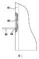
図1は、冷蔵庫扉01を備え、冷蔵庫扉01に貯蔵空間(図示しない)が設けられ、貯蔵空間の開口部02外に副扉03が設けられ、副扉03の回転軸04が開口部02の底部に水平に設けられており、副扉03が回転軸04回りに回転することで開口部02を開閉可能にする、従来技術の冷蔵庫を示すものである。よく使われる慣用物品が冷蔵庫扉01における貯蔵空間内に保管されており、取り出す際に副扉03を開けばよいため、大体積の冷蔵庫扉01の頻繁な開閉が避けられ、冷蔵庫内の冷却エネルギーの漏れを減らし、冷蔵庫のエネルギー消費量を低減した。
FIG. 1 includes a
副扉03を開く時、副扉03が回転軸04回りに回転するにつれて、副扉03と冷蔵庫扉01との間の角度が大きくなることで、冷蔵庫が占めるスペースが増大し、副扉03を完全に開いた後、一定の外部スペースを占め、不必要な制限をもたらし、しかも、ひとの前に阻む場合があるため、物品の取り出しが難しくなった。さらに、扉を開くたびに、冷蔵庫扉01の開口部02を完全に開くことになり、冷却エネルギーの損失が依然として大きかった。
When opening the
発明の開示
本発明の実施例は、冷蔵庫の副扉を開く時、冷蔵庫が占める外部スペースが増大し、物品の取り出しが難しくなり、さらに、開口部を完全に開くことによる冷却エネルギーの損失が深刻である、という従来技術の課題を解決できる冷蔵庫を提供する。
DISCLOSURE OF THE INVENTION The embodiment of the present invention increases the external space occupied by the refrigerator when opening the sub-door of the refrigerator, makes it difficult to take out articles, and the loss of cooling energy due to opening the opening completely is serious. The refrigerator which can solve the subject of the prior art that it is.
上記目的を達成するために、本発明の実施例は下記手段を採用する。
冷蔵庫主扉を備える冷蔵庫であって、前記冷蔵庫主扉の扉体に開口部が設けられ、前記開口部のエッジにガイドレールが設けられ、前記ガイドレール上に副扉が適合して配置され、前記副扉に、前記副扉を前記ガイドレールに沿って摺動させるように駆動可能である駆動手段が接続され、前記副扉が前記ガイドレールに沿って摺動することにより、前記副扉が前記開口部を開閉可能にする冷蔵庫を提供する。
In order to achieve the above object, the embodiment of the present invention adopts the following means.
A refrigerator including a refrigerator main door, wherein an opening is provided in a door body of the refrigerator main door, a guide rail is provided at an edge of the opening, and a sub-door is fitted on the guide rail, Drive means capable of driving the sub door to slide along the guide rail is connected to the sub door, and the sub door slides along the guide rail so that the sub door is Provided is a refrigerator capable of opening and closing the opening.
本発明の実施例に係る冷蔵庫は、冷蔵庫主扉上に副扉が設けられており、物品を出し入れする際に、駆動手段によって副扉をガイドレールに沿って摺動させるように駆動して、冷蔵庫主扉における開口部を開くことで、冷蔵庫内の物品を取り出すことができ、そして、駆動手段によって副扉をガイドレールに沿って逆方向に摺動させるように駆動して、冷蔵庫主扉における開口部を閉めることができる。本発明の実施例に係る冷蔵庫は、よく使われる物品の出し入れに際して、体積の小さい副扉を部分的に又は完全に開くことができるため、冷蔵庫内の冷却エネルギーの損失を減らし、利用者による物品の出し入れを便利にし、利用者の体験を高めることができる。しかも、副扉を開いた時、副扉が冷蔵庫主扉内に位置し、冷蔵庫主扉と同一平面に位置するため、ひとの前に阻むことなく、冷蔵庫が占める外部スペース及び物品の取り出し難さに影響を与えない。 The refrigerator according to the embodiment of the present invention is provided with a sub-door on the refrigerator main door, and drives the sub-door to slide along the guide rail by the driving means when putting in / out the article, By opening the opening in the refrigerator main door, articles in the refrigerator can be taken out, and the sub door is driven to slide in the reverse direction along the guide rail by the driving means. The opening can be closed. The refrigerator according to the embodiment of the present invention can partially or completely open the small-volume sub door when taking in and out frequently used articles, thereby reducing the loss of cooling energy in the refrigerator and reducing the amount of goods by the user. This makes it easy to put in and take out and enhance the user experience. Moreover, when the sub door is opened, the sub door is located in the refrigerator main door and is flush with the main door of the refrigerator. Does not affect.
本発明の実施例又は従来技術の発明をより明確に説明するために、以下、実施例又は従来技術に対する説明において使用する必要のある図面を簡単に紹介する。明らかなように、下記説明する図面はただ本発明のいくつかの実施例だけであり、当業者にとって、格別な創意工夫を要せず、これらの図面に基づいてその他の図面を得ることができる。
具体的な実施形態
以下、本発明の実施例の図面に合わせて本発明の実施例の形態を明確で完全に説明する。明らかなように、かかる実施例は全部の実施例ではなく、ただ本発明の一部の実施例だけである。本発明の実施例に基づいて、当業者が創意工夫を要せずになし得たすべてのその他の実施例はいずれも本発明の範囲に属する。
Specific Embodiments Hereinafter, embodiments of the present invention will be described clearly and completely with reference to the drawings of the embodiments of the present invention. Obviously, such embodiments are not all embodiments, but only some embodiments of the present invention. Based on the embodiments of the present invention, all other embodiments that can be made by those skilled in the art without ingenuity belong to the scope of the present invention.
本発明の記述においては、「中心」、「上」、「下」、「前」、「後」、「左」、「右」、「縦」、「水平」、「頂上」、「底」、「内」、「外」などの用語によって指示される方位や位置関係があれば、それは添付図面に示される方位や位置関係に基づくものであり、かかる装置や素子が特定の方位を有し、また、特定の方位で構成されたり動作したりしなければならないと明示または示唆するものではなく、ただ、本発明を記述しやすくしたり記述を簡略化したりするためであるので、本発明を限ると理解するべきではない。 In the description of the present invention, “center”, “top”, “bottom”, “front”, “back”, “left”, “right”, “vertical”, “horizontal”, “top”, “bottom” If there is an orientation or positional relationship indicated by terms such as “inside” or “outside”, it is based on the orientation or positional relationship shown in the accompanying drawings, and such a device or element has a specific orientation. It is not explicitly or implied that the apparatus must be constructed or operated in a specific orientation, but is merely for ease of description or to simplify the description. It should not be understood as limited.
「第一」、「第二」という用語は、相対的な重要性を明示または示唆するか、又はかかる技術的特徴の数を暗示するものであると理解すべきではなく、ただ目的を記述するためのものだけである。したがって、「第一」、「第二」を規定した特徴は、1つ又はそれ以上の当該特徴を含むことを明示または示唆することができる。本発明の記述において、説明がなければ、「複数」の意味は2つ又は2つ以上を指す。 The terms “first” and “second” should not be understood to imply or imply relative importance or imply the number of such technical features, but merely describe the purpose. It is only for the purpose. Thus, a feature defining “first”, “second” can expressly or suggest that it includes one or more such features. In the description of the present invention, if there is no explanation, the meaning of “plurality” refers to two or more.
本発明の記述において、明確な規定と限定とがなければ、「装着」、「連結」、「接続」という用語は広く理解されるべきである。例えば、固定接続でもよく、着脱可能な接続でもよく、一体的な接続でもよい。直接連結でもよく、中間媒体を通じた間接的な連結でもよく、2つの素子の内部の連通でもよい。当業者にとって、具体的な状況に応じて上記用語の本発明における具体的な意味を理解することができる。 In the description of the present invention, the terms “attachment”, “coupling” and “connection” should be broadly understood unless there is a clear definition and limitation. For example, a fixed connection, a detachable connection, or an integral connection may be used. It may be a direct connection, an indirect connection through an intermediate medium, or an internal communication between two elements. For those skilled in the art, the specific meaning of the above terms in the present invention can be understood depending on the specific situation.
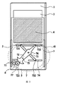
図2は本発明の実施例の冷蔵庫の具体的な一実施例を示すものである。本実施例に係る冷蔵庫は冷蔵庫主扉1を備え、冷蔵庫主扉1の扉体に開口部2が設けられ、開口部2のエッジにガイドレール3が設けられ、ガイドレール3に副扉4が適合して配置され、副扉4に、副扉4をガイドレール3に沿って摺動するように駆動可能である駆動手段5が接続され、副扉4がガイドレール3に沿って摺動することにより、副扉4が開口部2を開閉可能にする。
FIG. 2 shows a specific embodiment of the refrigerator according to the embodiment of the present invention. The refrigerator according to the present embodiment includes a refrigerator
本発明の実施例に係る冷蔵庫は、冷蔵庫主扉1に副扉4が設けられ、物品を出し入れする際に、駆動手段5によって副扉4をガイドレール3に沿って摺動させるように駆動して、冷蔵庫主扉1における開口部2を開くことで、冷蔵庫内の物品を取り出すことができ、そして、駆動手段5によって副扉4をガイドレール3に沿って逆方向に摺動させるように駆動して、冷蔵庫主扉1における開口部2を閉める。本発明の実施例に係る冷蔵庫は、よく使われる物品の出し入れに際して、体積の小さい副扉4を部分的に又は完全に開くことができるため、冷蔵庫内の冷却エネルギーの損失を減らし、利用者による物品の出し入れを便利にし、利用者体験を高めることができる。しかも、副扉4を開いた時、副扉4が冷蔵庫主扉1内に位置し、冷蔵庫主扉1と同一平面に位置するため、ひとの前に阻むことなく、冷蔵庫が占める外部スペース及び物品の取り出し難さに影響を与えない。副扉4がガイドレール3に沿って摺動するという扉の開き方は、摩耗しやすいドアヒンジ部材が不要となり、冷蔵庫副扉4の耐久性が向上し、かつ、駆動手段5による副扉4の開閉を可能にし、冷蔵庫の自動化の発展に利する。
In the refrigerator according to the embodiment of the present invention, the refrigerator
開口部2のエッジにガイドレール3を設けることは、下記2つの形態で実施することができる。1つ目の実施形態は、開口部2の片側エッジのみにガイドレール3を配置することである。この場合、副扉4の摺動は、片側のガイドレール3で副扉4の対応する片側エッジを制限することによって実現されるので、副扉4の摺動の安定性が低い。2つ目の実施形態は、開口部2の対向する2つのエッジにそれぞれガイドレール3を平行に配置し、両側ガイドレール3で副扉4の両側エッジを制限することである。この実施形態では、副扉4の摺動がより安定している。したがって、開口部2の対向する2つのエッジにそれぞれガイドレール3を配置することが好ましい。
Providing the
本実施例では、駆動手段5はモータ6及び伝動ユニット7を備え、モータ6の出力軸が伝動ユニット7に駆動接続され、伝動ユニット7が副扉4に駆動接続され、伝動ユニット7がモータ6の出力軸の回転運動を直線運動に変換して副扉4をガイドレール3に沿って摺動させるように駆動可能である。伝動ユニット7によってモータ6の動力を副扉4に伝達して、副扉4をガイドレール3に沿って摺動させることで、冷蔵庫主扉1における開口部2の開閉を可能にする。
In this embodiment, the drive means 5 includes a
図2は伝動ユニット7の一実施形態を示すものである。第一のギア71と、第一の軸75によって冷蔵庫主扉1の扉体に接続され、第一の軸75回りに回転可能である第一のリンク72と、第二の軸76によって第一のリンク72とヒンジ連結されている第二のリンク73とを備え、第一のギア71がモータ6の出力軸に固定され、第一のリンク72の一端がギア構造721であり、他端に第一のガイドピン722が接続され、ギア構造721が第一のギア71に噛み合い、副扉4の駆動手段5に近寄る側に、ガイドレール3に垂直に第一のシュート41が設けられ、第一のガイドピン722が第一のシュート41内に適合して配置され、第二のリンク73の一端に第二のガイドピン731が接続され、他端に第三のガイドピン732が接続され、第二のガイドピン731が第一のシュート41内に適合して配置され、冷蔵庫主扉1の扉体上に、ガイドレール3に垂直に第二のシュート74が設けられ、第三のガイドピン732が第二のシュート74内に適合して配置されている。副扉4が閉状態から開状態になる時、モータ6が起動して第一のギア71を動かしてモータ軸回りに反時計回転させる。第一のギア71とギア構造721とが噛み合っているため、第一のギア71が第一のリンク72を動かして第一の軸75回りに時計回りに回転させるのと同時に、第二の軸76を動かして第一の軸75回りに時計回りに回転させる。この時、第一のガイドピン722が第一のシュート41に沿って第一のギア71から離れる方向に摺動し、第二のリンク73が第二の軸76回りに反時計回転することで、第二のガイドピン731が第一のシュート41に沿って第一のガイドピン722の摺動方向と反対の方向に摺動し、第三のガイドピン732が第二のシュート74に沿って第一のガイドピン722の摺動方向と同じ方向に摺動することによって、開口部2が完全に開くまで副扉4を動かしてガイドレール3に沿って第一のギア71に近づく方向に摺動させる。副扉4が開状態から閉状態になる時、モータ6が起動して第一のギア71を動かしてモータ軸回りに時計回りに回転させる。第一のギア71とギア構造721とが噛み合っているため、第一のギア71が第一のリンク72を動かして第一の軸75回りに反時計回転させるのと同時に、第二の軸76を動かして第一の軸75回りに反時計回転させる。この時、第一のガイドピン722が第一のシュート41に沿って第一のギア71に近づく方向に摺動し、第二のリンク73が第二の軸76回りに時計回りに回転することで、第二のガイドピン731が第一のシュート41に沿って第一のガイドピン722の摺動方向と反対の方向に摺動し、第三のガイドピン732が第二のシュート74に沿って第一のガイドピン722の摺動方向と同じ方向に摺動することによって、開口部2が完全に閉まるまで副扉4を動かしてガイドレール3に沿って第一のギア71から離れる方向に摺動させる。第一のギア71と第一のリンク72におけるギア721とが噛み合って、モータ6の動力を第一のリンク72及び第二のリンク73に伝達することにより、第一のリンク72及び第二のリンク73が副扉4をガイドレール3に沿って安定的に摺動させるように駆動して、開口部2の開閉を可能にする。当該伝動ユニット7の支持能力及び衝撃耐性が強いため、伝動している間の摩耗が小さく、しかも製造が便利であり、生産時に高精度を得やすい。
FIG. 2 shows an embodiment of the
上記実施例において、第二のシュート74が冷蔵庫主扉1の扉体に設けられているため、冷蔵庫主扉1の対応する位置の強度が低下する。第二のシュート74が壊れると、全冷蔵庫主扉1が廃棄されることになる。このような状況を回避するために、本発明の別の実施例において、冷蔵庫主扉1の扉体に、ガイドレール3に垂直に支持レバー(図示しない)を設け、第二のシュート74を支持レバーに設置し、第三のガイドピン732を第二のシュート74内に適合して配置することが好ましい。これで、第二のシュート74が壊れた場合に、支持レバーを取り換えればよく、全冷蔵庫主扉1の廃棄を回避できるとともに、冷蔵庫主扉1の強度に影響を及ぼさないことを保証できる。
In the said Example, since the 2nd chute | shoot 74 is provided in the door body of the refrigerator
上記実施例において、第一のリンク72が揺動している間に、ギア構造721の一部の歯のみを利用したため、また、ギア構造721の材料の節約及びその加工プロセスの簡略化のため、ギア構造721は、図2に示すセクタギア構造を採用することが好ましい。
In the above-described embodiment, only a part of the teeth of the
図3を参照すれば、本発明の実施例の伝動ユニット7は第二のギア77をさらに備え、ギア構造721が第二のギア77によって第一のギア71と噛み合っている。
伝動ユニット7の別の実施形態は、ギアラックを利用して伝動することができ、伝動ギアと、ラックと、前記冷蔵庫主扉1の扉体に固定されるラックガイドレールとを備え、前記ラックガイドレールが前記ガイドレール3と平行し、前記ラックが前記ラックガイドレールに沿って摺動可能であり、前記ラックの一端が前記副扉4に接続され、前記伝動ギアが前記モータ6の出力軸に駆動接続され、かつ前記ラックに噛み合っている。副扉4が閉状態から開状態になる時、モータ6が起動して伝動ギアを動かしてモータ軸回りに反時計回転させる。この時、伝動ギアと噛み合っているラックがラックガイドレールに沿って摺動することで、開口部2が完全に開くまで副扉4を動かしてガイドレール3に沿って伝動ギアに近づく方向に摺動させる。副扉4が開状態から閉状態になる時、モータ6が起動して伝動ギアを動かしてモータ軸回りに時計回りに回転させる。この時、伝動ギアと噛み合っているラックがラックガイドレールに沿って摺動することで、開口部2が完全に閉まるまで副扉4を動かしてガイドレール3に沿って伝動ギアから離れる方向に摺動させる。ギアラックによってモータ6の出力軸の回転運動を直線運動に変換し、副扉4をガイドレール3に沿って摺動させるように駆動することで、開口部2の開閉を可能にする。この伝動ユニット7は、変速比を一定にすることができ、しかも伝動効率が高く、伝動が安定的であるので、ガイドレール3に沿う副扉4の摺動をより安定化することができ、使用寿命をより長くすることができる。
Referring to FIG. 3, the
Another embodiment of the
上記実施例において、伝動ギア、ラック及びラックガイドレールはいずれも1つであってもよく、モータ6が起動すると当該伝動ギアを動かして回転させ、伝動ギアが回転してそれに噛み合っているラックを動かしてラックガイドレールに沿って摺動させることで、ラックによって副扉4を動かしてガイドレールに沿って摺動させ、開口部2の開閉を可能にする。
In the above embodiment, the transmission gear, the rack, and the rack guide rail may all be one, and when the
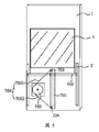
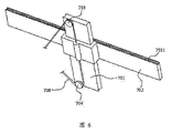
本発明の別の実施例において、伝動ギア、ラック及びラックガイドレールはいずれも2つあってもよい。図4を参照すれば、具体的には、伝動ギアは第三のギア78及び第四のギア79という2つのギアを含み、ラック710及びラックガイドレール711はいずれも2つあり、2つのラック710が距離を置いて配置され、しかもいずれもガイドレール3に平行しており、かつ、2つのラック710の一端がいずれも副扉4に接続され、2つのラックガイドレール711が距離を置いて配置され、しかもいずれもガイドレール3に平行しており、2つのラック710がそれぞれ2つのラックガイドレール711に適合して接続されている。第三のギア78がモータ6の出力軸に固定され、第三のギア78が1つのラック710及び第四のギア79にそれぞれ噛み合っており、第四のギア79が別のラック710に噛み合っている。副扉4が閉状態から開状態になる時、モータ6が起動して第三のギア78を動かしてモータ軸回りに反時計回転させる。この時、第三のギア78に噛み合っている第四のギア79がその回転中心回りに時計回りに回転し、第三のギア78及び第四のギア79が、それぞれに噛み合っている2つのラック710を動かしてラックガイドレール711に沿って摺動させることにより、開口部2が完全に開くまで副扉4を動かしてガイドレール3に沿って第三のギア78に近づく方向に摺動させる。副扉4が開状態から閉状態になる時、モータ6が起動して第三のギア78を動かしてモータ軸回りに時計回りに回転させる。この時、第三のギア78に噛み合っている第四のギア79がその回転中心回りに反時計回転し、第三のギア78及び第四のギア79が、それに噛み合っている2つのラック710を動かしてラックガイドレール711に沿って摺動させることにより、開口部2が完全に閉まるまで副扉4を動かしてガイドレール3に沿って第三ギア78から離れる方向に摺動させる。伝動ギア、ラック及びラックガイドレールはいずれも2つあるので、副扉4の摺動を駆動する際に両側駆動であり、片側駆動に比して、本実施形態では、副扉4の力受けをより均一にし、副扉4が摺動している間に嵌合することを回避できるので、伝動ギア、ラック及びラックガイドレールをいずれも2つにすることが好ましい。
In another embodiment of the present invention, there may be two transmission gears, racks, and rack guide rails. Referring to FIG. 4, specifically, the transmission gear includes two gears, a
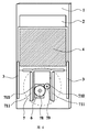
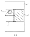
図5、図6に示すように、本発明の別の実施例において、伝動ユニット7は、ガイドレール3と平行する方向に沿って設けられたガイドブロック701を備え、ガイドブロック701の両端にそれぞれ第一のガイドプーリ703及び第二のガイドプーリ704が設けられ、モータ6の出力軸に主駆動輪705が外嵌され、副扉4が、ガイドブロック701に外嵌されかつガイドブロック701に沿って摺動可能である摺動基板702を備え、摺動基板702が第一のガイドプーリ703と第二のガイドプーリ704との間に位置し、摺動基板702に伝動ロープ706が接続され、伝動ロープ706が、摺動基板702の両側にそれぞれ位置する第一の伝動ロープ7061及び第二の伝動ロープ7062を備え、第一伝動ロープ7061が第一のガイドプーリ703を迂回して配置されかつ第一の方向に沿って主駆動輪705上に巻き付け固定され、第二の伝動ロープ7062が第二のガイドプーリ704を迂回して配置されかつ前記第一の方向と反対の方向に主駆動輪705上に巻き付け固定されている。
As shown in FIG. 5 and FIG. 6, in another embodiment of the present invention, the
上記実施例の作業過程は以下のとおりである。副扉4が開位置から閉位置に移動する時、モータ6の出力軸が主駆動輪705を動かして反時計回転させることにより、第一の伝動ロープ7061を引張って、第二の伝動ロープ7062を緩めることで、第一のガイドプーリ703と第二のガイドプーリ704との間に位置する伝動ロープ部分が力を受けて上に移動し、ガイドブロック701及びガイドレール3の方向誘導の作用下で、摺動基板702を引っ張って副扉4を動かして上に移動させ、閉位置に至る。副扉4が閉位置から開位置に移動する時、モータ6の出力軸が主駆動輪705を動かして時計回りに回転させることにより、第二の伝動ロープ7062を引張って、第一の伝動ロープ7061を緩めることで、第一のガイドプーリ703と第二のガイドプーリ704との間に位置する伝動ロープを下に移動させ、ガイドブロック701及びガイドレール3の方向誘導の作用下で、摺動基板702を引っ張って副扉4を動かして下に移動させ、開状態に至る。図5に示す伝動構造は、一般の伝動構造に比べて、組み立てる部品の点数を削減でき、生産効率を向上でき、しかも、伝動ロープと主駆動輪とガイドプーリとは連続的に組み合っており、かつ伝動ロープが可撓性の部材であるので、ギア伝動に比して、歯同士が噛み合う際に生じる摩擦や衝突を回避でき、こうして伝動時のノイズを減少させることができる。
The working process of the above embodiment is as follows. When the
副扉の力受け方向とガイドレール3の配置方向とを一致させるために、第一のガイドプーリ703及び第二のガイドプーリ704の位置及び大きさを設定することにより、伝動ロープ706の第一のガイドプーリ703と第二のガイドプーリ704との間に位置する部分をガイドレール3に平行にすることが考えられる。例えば、第一のガイドプーリ703と第二のガイドプーリ704とを、半径が同じでかつ中心が同一直線に位置するように設定することが考えられる。こうすれば、副扉の力受け方向とガイドレール3の配置方向とを一致させることができ、動作している間に引っかかる現象の発生を防止できる。
By setting the positions and sizes of the
主駆動輪705上に巻き付けられた第一の伝動ロープ7061及び第二の伝動ロープ7062が互いに妨害することを防止するために、図7に示すように、主駆動輪705の外周全周に沿って第一のガイド溝7051及び第二のガイド溝7052が平行に周設され、第一の伝動ロープ7061が第一のガイドプーリ703を迂回して配置されかつ前記第一方向に沿って第一のガイド溝7051内に巻き付けられ、かつ第一のガイド溝7051に固定接続され、第二の伝動ロープ7062が第二のガイドプーリ704を迂回して配置されかつ前記第一方向と反対の方向に沿って第二のガイド溝7052に巻き付けられ、かつ第二のガイド溝7052に固定接続されることが好ましい。これで、副扉4が開位置から閉位置に移動する時、モータ6の出力軸が主駆動輪705を動かして反時計回転させることにより、第一の伝動ロープ7061を引っ張って第一のガイド溝7051内に段々巻き付け、かつ第二の伝動ロープ7062を緩めて第二の伝動ロープ7062を第二のガイド溝7052から段々離すことで、第一のガイドプーリ703と第二のガイドプーリ704との間に位置する伝動ロープ部分が力を受けて上に移動し、ガイドブロック701及びガイドレール3の方向誘導の作用下で、摺動基板702を引っ張って副扉4を動かして上に移動させ、閉位置に至る。このように、主駆動輪705に2層ガイド溝の構造を採用することにより、主駆動輪705に巻き付けられた第一の伝動ロープ7061と第二の伝動ロープ7062とを互いから離間することができ、伝動している間に相互に接触・摩擦することで副扉の移動の抵抗を増やすことを防止できる。
In order to prevent the
伝動ロープ706が主駆動輪705に巻き付けられた長さは、副扉が完全閉の位置と完全開の位置との間に移動する距離を満足できる長さのはずであり、そうでなければ、完全閉の位置と完全開の位置との間に副扉の移動全過程を保証できない。具体的には、副扉が完全閉の位置(つまり図5に示す位置)にある時、第一のガイド溝7051内に巻き付けられた伝動ロープ706の長さは、前記移動距離に等しいか、又はそれより長いはずである。
The length of the transmission rope 706 wound around the
説明しなければならないのは、副扉が極限位置に移動した時、伝動ロープ706の主駆動輪705に巻き付けられた部分は完全に解放される可能性がある。このような極限状況も、本発明の実施例に記載の「巻き付け」の解釈範囲に属する。
It should be explained that when the secondary door moves to the extreme position, the portion of the transmission rope 706 wound around the
上記実施例において、伝動ロープ706は全体的に1本のロープであってもよく、分けられた2本のロープであってもよい。伝動ロープ706が全体的に1本のロープである場合に、伝動ロープ706の中間部が摺動基板702に貫通して接続され、伝動ロープ706が分けられた2本のロープである場合に、図6に示すように、2本の伝動ロープはそれぞれ摺動基板702の上下両端に接続されている。
In the above embodiment, the transmission rope 706 may be a single rope as a whole or may be two separated ropes. When the transmission rope 706 is a single rope as a whole, when the intermediate portion of the transmission rope 706 is connected through the sliding
図8に示すように、摺動基板702がガイドブロック701に沿って摺動する時の摩擦力を減少させるために、摺動基板702とガイドブロック701との間にプーリ7022を配置することが考えられる。具体的には、摺動基板702のガイドブロック701と接触する内壁上に回転自在なプーリ7022を設けて、次に摺動基板702をガイドブロック701上に外嵌することが考えられる。こうすれば、摺動基板702とガイドブロック701との摺動は、プーリ7022によって支持されることで、摺動基板702がガイドブロック701に沿って摺動する際の摩擦力を転がり摩擦力にすることができ、副扉の運動抵抗を大幅に低減できる。
As shown in FIG. 8, a pulley 7022 may be disposed between the sliding
伝動ロープ706は、耐摩耗性のより良い鋼線を採用することが好ましい。
図6に示すように、摺動基板702と副扉4との接続をより強固にするために、摺動基板702の副扉に向く表面に装着溝7021を設置し、副扉のエッジを装着溝7021内に係合配置することが好ましい。こうすれば、伝動している間に副扉と摺動基板702とが離脱することを防止できる。
The transmission rope 706 is preferably a steel wire with better wear resistance.
As shown in Fig. 6, in order to strengthen the connection between the sliding
副扉4の駆動手段5が冷蔵庫主扉1の扉体内に設けられるため、冷蔵庫主扉1の対応する位置における気泡層の厚みが小さくなり、冷蔵庫主扉1の保温性能が低下する。冷蔵庫主扉1の保温性能を維持するために、図10に示すように、冷蔵庫主扉1の内壁の駆動手段5と対応する位置に内壁面から突出した肥厚層11を設け、肥厚層11を配置することにより冷蔵庫主扉1の保温性能を高める。
Since the driving means 5 of the
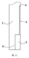
また、図11を参照すれば、駆動手段5の外面に真空断熱板8を設け、真空断熱板8を配置することにより冷蔵庫主扉1の保温性能を高めることもできる。
図10〜図13を参照すれば、副扉4が閉められた時に開口部2のシール性を保証するために、開口部2の内壁全周に沿ってウエザストリップ9が周設され、ウエザストリップ9の副扉4に向く側に凹溝91が設けられ、凹溝91内に弾性突起92が設けられ、副扉4が閉められた時、副扉4のエッジが凹溝91内に入り込んで弾性突起92を押圧可能である。この時、弾性突起92が副扉4に密に接しているので、副扉4が閉められた時に開口部2のシール性を保証できる。
Referring to FIG. 11, the heat insulating performance of the refrigerator
Referring to FIGS. 10 to 13, in order to guarantee the sealing performance of the opening 2 when the
弾性突起92の使用寿命を長くするとともに、副扉4とウエザストリップ9との接続箇所のシール性及び易滑性を向上するために、弾性突起92の外面に植毛処理によって毛が植設されている。こうすれば、弾性突起92の耐摩擦性を向上できるので、弾性突起92の使用寿命を長くするとともに、副扉4とウエザストリップ9との接続箇所のシール性及び易滑性を向上することができる。
In order to prolong the service life of the
ウエザストリップ9が開口部2の内壁に設けられ、開口部2の内壁の温度が低いため、開口部2のシール性を保証するようにウエザストリップ9が低温度であっても良好な弾性を維持しなければならない。ウエザストリップ9の材料としては、EPDM(Ethylene-Propylene-Diene Monomer、エチレン - プロピレン - ジエンゴム)、TPE(Thermoplastic Elastomer、熱可塑性エラストマー)又はTPR(Thermoplastic Rubber、熱可塑性ゴム)が好ましく挙げられる。上記3つの材料は低温度の環境であっても弾性性能が良好であるので、開口部2のシール性を保証できる。
Since the
冷蔵庫の保温性能を高めるために、副扉4は断熱ガラスから製造される。断熱ガラスは冷蔵庫内の冷却エネルギーの滲み出しを防止できるので、冷蔵庫の保温性能を高めることができる。また、利用者は冷蔵庫主扉1及び副扉4がいずれも閉められた場合に、副扉4を通じて冷蔵庫内の物品の保管状況を確認することができ、物品の取り出しに利する。
In order to improve the heat retaining performance of the refrigerator, the
本実施例のガイドレール3は縦方向に沿って配置することができる。この時、副扉4はガイドレール3に沿って上下に摺動可能である。また、図9に示すように、ガイドレール3は水平方向に沿って配置することもできる。この時、副扉4はガイドレール3に沿って左右に摺動可能である。冷蔵庫主扉1内の棚が水平に配置されれば、ガイドレール3が水平方向に配置されると、副扉4を完全に開いたとしても、棚にある物品の半分しか取り出すことができない。一方、ガイドレール3が縦方向に配置されば、副扉4を一部開いただけで、棚の全層の物品を取り出すことができる。例えば棚の上層にある物品を取り出したい場合、副扉4の上半部分を開けばよく、冷却エネルギーの損失も低減できる。したがって、ガイドレール3を縦方向に沿って配置することが好ましい。
The
図14を参照すれば、ガイドレール3に沿う副扉4の摺動をより安定化するために、ガイドレール3の両側の内壁にそれぞれ回転自在な案内輪31が設けられる。副扉4がガイドレール3に沿って摺動する時、副扉4の両側の表面がそれぞれ案内輪31に密接し、案内輪31によって副扉4の位置を制限し、副扉4が摺動している間に両側に揺れることを防止することで、ガイドレール3に沿う副扉4の摺動をより安定化することができる。また、案内輪31の材料としては、案内輪31がガラス製副扉4にスクラッチを残し、外観性に影響を与えることを防止する考えから、ゴム又はナイロンが好ましい。
Referring to FIG. 14, in order to further stabilize the sliding of the
以上は本発明の具体的な実施形態にすぎず、本発明の技術的範囲はこれらに制限されていない。本技術分野に詳しい当業者が本発明に開示している技術的範囲において容易に想到し得る変化や代替は、本発明の技術的範囲に含まれるべきである。したがって、本発明の技術的範囲は、請求項の技術的範囲に準じる。 The above are only specific embodiments of the present invention, and the technical scope of the present invention is not limited thereto. Changes and alternatives that can be easily conceived by those skilled in the art within the technical scope disclosed in the present invention should be included in the technical scope of the present invention. Therefore, the technical scope of the present invention conforms to the technical scope of the claims.
Claims (12)
ことを特徴とする冷蔵庫。 A refrigerator including a refrigerator main door, wherein an opening is provided in a door body of the refrigerator main door, a guide rail is provided at an edge of the opening, and a sub-door is fitted on the guide rail, Drive means capable of driving the sub door to slide along the guide rail is connected to the sub door, and the sub door slides along the guide rail so that the sub door is A refrigerator characterized in that the opening can be opened and closed.
ことを特徴とする請求項1に記載の冷蔵庫。 The driving means includes a motor and a transmission unit, the output shaft of the motor is drivingly connected to the transmission unit, the transmission unit is drivingly connected to the sub door, and the transmission unit performs the rotational movement of the output shaft of the motor. 2. The refrigerator according to claim 1, wherein the refrigerator is driven so as to be slid along the guide rail after being converted into a linear motion.
ことを特徴とする請求項2に記載の冷蔵庫。 The transmission unit is connected to the door body of the refrigerator main door by a first gear and a first shaft, and is rotatable around the first shaft, the first link and the second link. A first link is fixed to the output shaft of the motor, one end of the first link is a gear structure, and the other end is a first structure. A guide pin is connected, the gear structure meshes with the first gear, and a first chute is provided perpendicularly to the guide rail on the side of the sub door approaching the driving means, and the first guide pin Is fitted in the first chute, a second guide pin is connected to one end of the second link, a third guide pin is connected to the other end, and the second guide pin is The refrigerator main is arranged in conformity with the first chute. The second chute is provided on the door body perpendicularly to the guide rail, and the third guide pin is disposed in conformity with the second chute. The refrigerator described.
ことを特徴とする請求項2に記載の冷蔵庫。 The transmission unit includes a transmission gear, a rack, and a rack guide rail fixed to a door body of the refrigerator main door, the rack guide rail is parallel to the guide rail, and the rack is connected to the rack guide rail. 3. The slide according to claim 2, wherein one end of the rack is connected to the sub door, the transmission gear is drivingly connected to the output shaft of the motor, and meshes with the rack. The refrigerator described.
ことを特徴とする請求項2に記載の冷蔵庫。 The transmission unit includes a guide block provided along a direction parallel to the guide rail, and a first guide pulley and a second guide pulley are provided at both ends of the guide block, respectively, and an output shaft of the motor A main driving wheel is externally fitted, and the sub-door includes a sliding board externally fitted to the guide block, and the sliding board is positioned between the first guide pulley and the second guide pulley. And a transmission rope is connected, and the transmission rope includes a first transmission rope and a second transmission rope respectively located on both sides of the sliding substrate, and the first transmission rope is the first guide pulley. Is disposed around the main drive wheel and fixed along the first direction, and the second transmission rope is disposed around the second guide pulley and the first direction. The refrigerator according to claim 2, characterized in that it is fixed wound around the main drive on wheels in the opposite direction.
ことを特徴とする請求項5に記載の冷蔵庫。 A first guide groove and a second guide groove are provided in parallel along the entire outer periphery of the main drive wheel, and the first transmission rope is disposed around the first guide pulley and Wound around and fixed in the first guide groove along one direction, the second transmission rope is disposed around the second guide pulley, and the second direction is opposite to the first direction. 6. The refrigerator according to claim 5, wherein the refrigerator is wound and fixed in the second guide groove.
ことを特徴とする請求項2〜6のいずれか一項に記載の冷蔵庫。 The driving means is provided in the door body of the main door, and a thickened layer protruding from the inner wall surface is provided at a position corresponding to the driving means on the inner wall of the main door. The refrigerator as described in any one of 6.
ことを特徴とする請求項2〜6のいずれか一項に記載の冷蔵庫。 The refrigerator according to any one of claims 2 to 6, wherein the driving means is provided in a door body of the main door, and a vacuum heat insulating plate is provided on an outer surface of the driving means.
ことを特徴とする請求項1に記載の冷蔵庫。 A weather strip is provided around the entire inner wall of the opening, a concave groove is provided on a side of the weather strip facing the sub door, an elastic protrusion is provided in the concave groove, and the sub door is provided. 2. The refrigerator according to claim 1, wherein when the door is closed, an edge of the sub door enters the concave groove to press the elastic protrusion.
ことを特徴とする請求項9に記載の冷蔵庫。 10. The refrigerator according to claim 9, wherein hair is planted on the outer surface of the elastic protrusion by a hair transplantation process.
ことを特徴とする請求項1に記載の冷蔵庫。 2. The refrigerator according to claim 1, wherein the sub door is manufactured from heat insulating glass.
ことを特徴とする請求項1に記載の冷蔵庫。 2. The refrigerator according to claim 1, wherein the guide rail is provided along a vertical direction, and the sub door is slidable up and down along the guide rail.
Applications Claiming Priority (5)
| Application Number | Priority Date | Filing Date | Title |
|---|---|---|---|
| CN201510009262.9 | 2015-01-07 | ||
| CN201510009262 | 2015-01-07 | ||
| CN201510107398.3A CN106032958B (en) | 2015-01-07 | 2015-03-11 | A kind of refrigerator |
| CN201510107398.3 | 2015-03-11 | ||
| PCT/CN2015/095263 WO2016110161A1 (en) | 2015-01-07 | 2015-11-23 | Refrigerator |
Publications (2)
| Publication Number | Publication Date |
|---|---|
| JP2017508122A true JP2017508122A (en) | 2017-03-23 |
| JP6632534B2 JP6632534B2 (en) | 2020-01-22 |
Family
ID=57150527
Family Applications (1)
| Application Number | Title | Priority Date | Filing Date |
|---|---|---|---|
| JP2016547910A Active JP6632534B2 (en) | 2015-01-07 | 2015-11-23 | refrigerator |
Country Status (4)
| Country | Link |
|---|---|
| US (1) | US10317125B2 (en) |
| JP (1) | JP6632534B2 (en) |
| KR (1) | KR20170056515A (en) |
| CN (1) | CN106032958B (en) |
Cited By (1)
| Publication number | Priority date | Publication date | Assignee | Title |
|---|---|---|---|---|
| CN113768291A (en) * | 2021-10-15 | 2021-12-10 | 浙江爱雪制冷电器有限公司 | Air-cooled freezing flat-cooling operation table |
Families Citing this family (13)
| Publication number | Priority date | Publication date | Assignee | Title |
|---|---|---|---|---|
| CN107044759B (en) * | 2017-01-20 | 2019-11-26 | 青岛海尔股份有限公司 | Door body assembly and refrigerator with the door body assembly |
| KR102308080B1 (en) * | 2017-04-05 | 2021-10-05 | 엘지전자 주식회사 | Refrigerator |
| CN108426401B (en) * | 2018-01-19 | 2020-09-29 | 青岛海尔股份有限公司 | Refrigerator with a door |
| CN108413694B (en) * | 2018-01-19 | 2020-07-28 | 青岛海尔股份有限公司 | Refrigerator with a door |
| CN108731341A (en) * | 2018-07-20 | 2018-11-02 | 阚建发 | A kind of refrigerator-freezer that can save energy |
| CN111765710B (en) * | 2019-04-02 | 2022-01-25 | 重庆海尔制冷电器有限公司 | Refrigerator with a door |
| CN111473597A (en) * | 2020-04-23 | 2020-07-31 | 长虹美菱股份有限公司 | Automatic lifting shelf device of refrigerator |
| CN111550962B (en) * | 2020-05-11 | 2021-10-29 | 海信(山东)冰箱有限公司 | Refrigerator with a door |
| CN111649529B (en) * | 2020-06-05 | 2021-12-17 | 长虹美菱股份有限公司 | Intelligent lifting shelf for refrigerator |
| CN113244425B (en) * | 2021-04-18 | 2023-07-25 | 邵贵林 | Apparatus sterilizing device for hematology department |
| USD946635S1 (en) | 2021-04-23 | 2022-03-22 | Gd Jg Electronic Ltd. | Refrigerator |
| CN114635963A (en) * | 2022-03-21 | 2022-06-17 | 成都华川电装有限责任公司 | Emergency switching mechanism of automobile door pump |
| CN115371333B (en) * | 2022-08-31 | 2023-11-24 | 海信冰箱有限公司 | Refrigerator with a refrigerator body |
Citations (12)
| Publication number | Priority date | Publication date | Assignee | Title |
|---|---|---|---|---|
| JPS477197Y1 (en) * | 1970-04-03 | 1972-03-15 | ||
| JPS5233818U (en) * | 1975-08-31 | 1977-03-10 | ||
| JPS58188473U (en) * | 1982-06-09 | 1983-12-14 | デルタ工業株式会社 | Automotive window regulator |
| JPS59134673U (en) * | 1983-02-28 | 1984-09-08 | 株式会社城南製作所 | Slider for automobile wire type wind regulator |
| JPS601872U (en) * | 1983-06-18 | 1985-01-09 | 日産車体株式会社 | Automotive door window regulator |
| JPH0230884U (en) * | 1988-08-23 | 1990-02-27 | ||
| JPH07276999A (en) * | 1994-04-15 | 1995-10-24 | Toyoda Gosei Co Ltd | Glass run for automobile |
| JPH08117123A (en) * | 1994-10-20 | 1996-05-14 | Sumitomo Forestry Co Ltd | Drain structure for kitchen tool or the like |
| JPH10153381A (en) * | 1996-11-21 | 1998-06-09 | Sanyo Electric Co Ltd | Chilled storage |
| CN1699901A (en) * | 2004-05-18 | 2005-11-23 | 乐金电子(天津)电器有限公司 | Domestic bar door of refrigerator |
| JP2010071565A (en) * | 2008-09-19 | 2010-04-02 | Hitachi Appliances Inc | Refrigerator |
| JP2011246988A (en) * | 2010-05-27 | 2011-12-08 | Shiroki Corp | Foreign matter pinching detector |
Family Cites Families (22)
| Publication number | Priority date | Publication date | Assignee | Title |
|---|---|---|---|---|
| JPS5233818A (en) | 1975-09-12 | 1977-03-15 | Kawasaki Steel Corp | Wire rod for drawing having little scale which is formed by oxidation at elevated temperature |
| ZA775054B (en) * | 1976-08-31 | 1978-09-27 | Wilmot Breeden Ltd | Improvements in regulator assemblies |
| US5595025A (en) * | 1995-05-01 | 1997-01-21 | Excel Industries, Inc. | Window regulator assembly |
| DE19521121C2 (en) * | 1995-06-09 | 1998-04-09 | Brose Fahrzeugteile | Device for connecting an arm window lifter to the sliding window pane of a motor vehicle |
| JP3931453B2 (en) * | 1998-11-06 | 2007-06-13 | アイシン精機株式会社 | Window door opening and closing device for vehicle sliding door |
| JP4838949B2 (en) * | 2001-06-26 | 2011-12-14 | 三洋昭和パネルシステム株式会社 | Stopper device for door in sliding door opening and closing device such as refrigerator |
| WO2006006707A1 (en) * | 2004-07-09 | 2006-01-19 | Matsushita Electric Industrial Co., Ltd. | Door device and refrigerator |
| US20060261220A1 (en) * | 2005-05-19 | 2006-11-23 | Samsung Electronics Co., Ltd. | Storage compartment with display support |
| KR101275568B1 (en) * | 2006-10-24 | 2013-06-14 | 엘지전자 주식회사 | Automatic Homebar |
| KR101508373B1 (en) * | 2008-01-21 | 2015-04-03 | 엘지전자 주식회사 | Refrigerator |
| JP5134985B2 (en) * | 2008-01-28 | 2013-01-30 | アスモ株式会社 | Opening and closing body drive device |
| KR20100071306A (en) | 2008-12-19 | 2010-06-29 | 삼성전자주식회사 | Refrigerator |
| US8069611B2 (en) * | 2009-05-12 | 2011-12-06 | Honda Motor Co., Ltd. | Door pane position sensor assembly |
| KR20100122230A (en) * | 2009-05-12 | 2010-11-22 | 엘지전자 주식회사 | Refrigerator |
| KR101687546B1 (en) * | 2009-07-28 | 2016-12-19 | 엘지전자 주식회사 | Refrigerator |
| US8707623B2 (en) * | 2010-06-23 | 2014-04-29 | Honda Motor Co., Ltd. | Window regulator assembly including a mechanism for securing a lift arm to a drive mechanism |
| EP2627957B1 (en) * | 2010-10-11 | 2019-11-06 | LG Electronics Inc. | Vacuum insulation glass panel and refrigerator having the same |
| CN102022889B (en) * | 2010-12-10 | 2013-01-23 | 海信科龙电器股份有限公司 | Rear cover component structure of bar counter door of refrigerator |
| US8650800B2 (en) * | 2012-03-09 | 2014-02-18 | Toyota Motor Engineering & Manufacturing North America, Inc. | Window lift assemblies for vehicles including window support bracket assemblies |
| KR101728196B1 (en) * | 2013-04-26 | 2017-04-18 | 엘지전자 주식회사 | Refrigerator |
| US10174554B2 (en) * | 2014-01-03 | 2019-01-08 | Jacek KUHNL-KINEL | Gate with counterweight and lowering exchangeable span |
| US9605891B2 (en) * | 2014-03-11 | 2017-03-28 | Samsung Electronics Co., Ltd. | Refrigerator |
-
2015
- 2015-03-11 CN CN201510107398.3A patent/CN106032958B/en active Active
- 2015-11-23 KR KR1020177004292A patent/KR20170056515A/en not_active Application Discontinuation
- 2015-11-23 JP JP2016547910A patent/JP6632534B2/en active Active
-
2016
- 2016-12-22 US US15/387,929 patent/US10317125B2/en active Active
Patent Citations (12)
| Publication number | Priority date | Publication date | Assignee | Title |
|---|---|---|---|---|
| JPS477197Y1 (en) * | 1970-04-03 | 1972-03-15 | ||
| JPS5233818U (en) * | 1975-08-31 | 1977-03-10 | ||
| JPS58188473U (en) * | 1982-06-09 | 1983-12-14 | デルタ工業株式会社 | Automotive window regulator |
| JPS59134673U (en) * | 1983-02-28 | 1984-09-08 | 株式会社城南製作所 | Slider for automobile wire type wind regulator |
| JPS601872U (en) * | 1983-06-18 | 1985-01-09 | 日産車体株式会社 | Automotive door window regulator |
| JPH0230884U (en) * | 1988-08-23 | 1990-02-27 | ||
| JPH07276999A (en) * | 1994-04-15 | 1995-10-24 | Toyoda Gosei Co Ltd | Glass run for automobile |
| JPH08117123A (en) * | 1994-10-20 | 1996-05-14 | Sumitomo Forestry Co Ltd | Drain structure for kitchen tool or the like |
| JPH10153381A (en) * | 1996-11-21 | 1998-06-09 | Sanyo Electric Co Ltd | Chilled storage |
| CN1699901A (en) * | 2004-05-18 | 2005-11-23 | 乐金电子(天津)电器有限公司 | Domestic bar door of refrigerator |
| JP2010071565A (en) * | 2008-09-19 | 2010-04-02 | Hitachi Appliances Inc | Refrigerator |
| JP2011246988A (en) * | 2010-05-27 | 2011-12-08 | Shiroki Corp | Foreign matter pinching detector |
Cited By (1)
| Publication number | Priority date | Publication date | Assignee | Title |
|---|---|---|---|---|
| CN113768291A (en) * | 2021-10-15 | 2021-12-10 | 浙江爱雪制冷电器有限公司 | Air-cooled freezing flat-cooling operation table |
Also Published As
| Publication number | Publication date |
|---|---|
| KR20170056515A (en) | 2017-05-23 |
| CN106032958B (en) | 2018-10-19 |
| JP6632534B2 (en) | 2020-01-22 |
| US10317125B2 (en) | 2019-06-11 |
| CN106032958A (en) | 2016-10-19 |
| US20170097184A1 (en) | 2017-04-06 |
Similar Documents
| Publication | Publication Date | Title |
|---|---|---|
| JP2017508122A (en) | refrigerator | |
| EP3091315B1 (en) | Refrigerator | |
| KR102100192B1 (en) | Refrigerator | |
| US8393694B2 (en) | Refrigerator with vertically moving member attached to home bar door | |
| CN109373689B (en) | Refrigerator capable of automatically opening and closing door | |
| US20060043849A1 (en) | Refrigerator having basket lift apparatus | |
| EP2333463A2 (en) | Refrigerator having door opening apparatus | |
| KR101447291B1 (en) | Apparatus for automatically opening door of refrigerator | |
| KR101129342B1 (en) | Shelf for refrigerator | |
| KR102412016B1 (en) | Refrigerator | |
| CN111174510B (en) | Refrigerator and method for changing volume of refrigerator chamber | |
| CN115822401A (en) | Hinge structure and refrigerator | |
| KR101624555B1 (en) | Damping device for refrigerator | |
| CN209978459U (en) | Refrigerating cabinet | |
| CN210738340U (en) | Door opening device and door opening household appliance thereof | |
| CN210425736U (en) | Automatic door of opening of constant temperature fridge | |
| CN215930272U (en) | Refrigerator door assembly with safety protection | |
| CN216581913U (en) | Freezing door opening device for liquid nitrogen tank and liquid nitrogen tank | |
| CN217083038U (en) | Pneumatic type buffering room | |
| CN219081313U (en) | Hinge structure and refrigerator | |
| CN217504119U (en) | Refrigerator door convenient to open door | |
| CN111829248B (en) | Ice storage box, ice making system and refrigerator | |
| KR101419321B1 (en) | Kim-Chi REFRIGERATOR | |
| KR20090004389U (en) | Refrigerator | |
| KR200435201Y1 (en) | The sliding door with the gear |
Legal Events
| Date | Code | Title | Description |
|---|---|---|---|
| A621 | Written request for application examination |
Free format text: JAPANESE INTERMEDIATE CODE: A621 Effective date: 20160721 |
|
| A977 | Report on retrieval |
Free format text: JAPANESE INTERMEDIATE CODE: A971007 Effective date: 20170621 |
|
| A131 | Notification of reasons for refusal |
Free format text: JAPANESE INTERMEDIATE CODE: A131 Effective date: 20170704 |
|
| A521 | Request for written amendment filed |
Free format text: JAPANESE INTERMEDIATE CODE: A523 Effective date: 20171003 |
|
| A02 | Decision of refusal |
Free format text: JAPANESE INTERMEDIATE CODE: A02 Effective date: 20180320 |
|
| A521 | Request for written amendment filed |
Free format text: JAPANESE INTERMEDIATE CODE: A523 Effective date: 20180720 |
|
| A911 | Transfer to examiner for re-examination before appeal (zenchi) |
Free format text: JAPANESE INTERMEDIATE CODE: A911 Effective date: 20180831 |
|
| A912 | Re-examination (zenchi) completed and case transferred to appeal board |
Free format text: JAPANESE INTERMEDIATE CODE: A912 Effective date: 20181012 |
|
| A601 | Written request for extension of time |
Free format text: JAPANESE INTERMEDIATE CODE: A601 Effective date: 20190702 |
|
| A521 | Request for written amendment filed |
Free format text: JAPANESE INTERMEDIATE CODE: A523 Effective date: 20190719 |
|
| A61 | First payment of annual fees (during grant procedure) |
Free format text: JAPANESE INTERMEDIATE CODE: A61 Effective date: 20191210 |
|
| R150 | Certificate of patent or registration of utility model |
Ref document number: 6632534 Country of ref document: JP Free format text: JAPANESE INTERMEDIATE CODE: R150 |
|
| R250 | Receipt of annual fees |
Free format text: JAPANESE INTERMEDIATE CODE: R250 |
|
| R250 | Receipt of annual fees |
Free format text: JAPANESE INTERMEDIATE CODE: R250 |