JP2017506358A - Lithographic apparatus and method - Google Patents
Lithographic apparatus and method Download PDFInfo
- Publication number
- JP2017506358A JP2017506358A JP2016545280A JP2016545280A JP2017506358A JP 2017506358 A JP2017506358 A JP 2017506358A JP 2016545280 A JP2016545280 A JP 2016545280A JP 2016545280 A JP2016545280 A JP 2016545280A JP 2017506358 A JP2017506358 A JP 2017506358A
- Authority
- JP
- Japan
- Prior art keywords
- mask
- area
- range
- reduction ratio
- patterned
- Prior art date
- Legal status (The legal status is an assumption and is not a legal conclusion. Google has not performed a legal analysis and makes no representation as to the accuracy of the status listed.)
- Pending
Links
- 238000000034 method Methods 0.000 title claims abstract description 31
- 230000009467 reduction Effects 0.000 claims abstract description 161
- 230000005855 radiation Effects 0.000 claims abstract description 143
- 239000000758 substrate Substances 0.000 claims abstract description 115
- 238000005286 illumination Methods 0.000 description 14
- 239000000463 material Substances 0.000 description 14
- 239000010410 layer Substances 0.000 description 11
- 238000000059 patterning Methods 0.000 description 11
- 238000001459 lithography Methods 0.000 description 10
- 230000008569 process Effects 0.000 description 10
- 238000010586 diagram Methods 0.000 description 9
- 230000008901 benefit Effects 0.000 description 8
- 230000007547 defect Effects 0.000 description 8
- 239000011358 absorbing material Substances 0.000 description 7
- 238000004519 manufacturing process Methods 0.000 description 7
- ATJFFYVFTNAWJD-UHFFFAOYSA-N Tin Chemical compound [Sn] ATJFFYVFTNAWJD-UHFFFAOYSA-N 0.000 description 6
- 239000000446 fuel Substances 0.000 description 6
- 230000015572 biosynthetic process Effects 0.000 description 4
- 230000000694 effects Effects 0.000 description 4
- 239000002245 particle Substances 0.000 description 4
- 239000002131 composite material Substances 0.000 description 3
- 239000003574 free electron Substances 0.000 description 3
- 210000001747 pupil Anatomy 0.000 description 3
- 230000035945 sensitivity Effects 0.000 description 3
- UFHFLCQGNIYNRP-UHFFFAOYSA-N Hydrogen Chemical compound [H][H] UFHFLCQGNIYNRP-UHFFFAOYSA-N 0.000 description 2
- 238000010521 absorption reaction Methods 0.000 description 2
- 239000011248 coating agent Substances 0.000 description 2
- 238000000576 coating method Methods 0.000 description 2
- 239000007789 gas Substances 0.000 description 2
- 238000010438 heat treatment Methods 0.000 description 2
- 239000001257 hydrogen Substances 0.000 description 2
- 229910052739 hydrogen Inorganic materials 0.000 description 2
- 239000002346 layers by function Substances 0.000 description 2
- 230000003287 optical effect Effects 0.000 description 2
- 235000012431 wafers Nutrition 0.000 description 2
- XUIMIQQOPSSXEZ-UHFFFAOYSA-N Silicon Chemical compound [Si] XUIMIQQOPSSXEZ-UHFFFAOYSA-N 0.000 description 1
- 239000006096 absorbing agent Substances 0.000 description 1
- 230000002411 adverse Effects 0.000 description 1
- 239000000956 alloy Substances 0.000 description 1
- 229910045601 alloy Inorganic materials 0.000 description 1
- 230000002457 bidirectional effect Effects 0.000 description 1
- 230000008859 change Effects 0.000 description 1
- 230000001427 coherent effect Effects 0.000 description 1
- 230000002301 combined effect Effects 0.000 description 1
- 239000000356 contaminant Substances 0.000 description 1
- 238000011109 contamination Methods 0.000 description 1
- 230000003247 decreasing effect Effects 0.000 description 1
- 230000001419 dependent effect Effects 0.000 description 1
- 230000008021 deposition Effects 0.000 description 1
- 238000001514 detection method Methods 0.000 description 1
- 238000009826 distribution Methods 0.000 description 1
- 230000005670 electromagnetic radiation Effects 0.000 description 1
- 230000007613 environmental effect Effects 0.000 description 1
- 230000006870 function Effects 0.000 description 1
- 238000003384 imaging method Methods 0.000 description 1
- 238000007689 inspection Methods 0.000 description 1
- 239000007788 liquid Substances 0.000 description 1
- 239000004973 liquid crystal related substance Substances 0.000 description 1
- 230000005381 magnetic domain Effects 0.000 description 1
- 238000005259 measurement Methods 0.000 description 1
- 230000015654 memory Effects 0.000 description 1
- 239000002184 metal Substances 0.000 description 1
- 238000012986 modification Methods 0.000 description 1
- 230000004048 modification Effects 0.000 description 1
- 230000006798 recombination Effects 0.000 description 1
- 238000005215 recombination Methods 0.000 description 1
- 238000004904 shortening Methods 0.000 description 1
- 229910052710 silicon Inorganic materials 0.000 description 1
- 239000010703 silicon Substances 0.000 description 1
- 239000010409 thin film Substances 0.000 description 1
Images


Classifications
-
- G—PHYSICS
- G03—PHOTOGRAPHY; CINEMATOGRAPHY; ANALOGOUS TECHNIQUES USING WAVES OTHER THAN OPTICAL WAVES; ELECTROGRAPHY; HOLOGRAPHY
- G03F—PHOTOMECHANICAL PRODUCTION OF TEXTURED OR PATTERNED SURFACES, e.g. FOR PRINTING, FOR PROCESSING OF SEMICONDUCTOR DEVICES; MATERIALS THEREFOR; ORIGINALS THEREFOR; APPARATUS SPECIALLY ADAPTED THEREFOR
- G03F7/00—Photomechanical, e.g. photolithographic, production of textured or patterned surfaces, e.g. printing surfaces; Materials therefor, e.g. comprising photoresists; Apparatus specially adapted therefor
- G03F7/70—Microphotolithographic exposure; Apparatus therefor
- G03F7/70216—Mask projection systems
- G03F7/70358—Scanning exposure, i.e. relative movement of patterned beam and workpiece during imaging
-
- G—PHYSICS
- G03—PHOTOGRAPHY; CINEMATOGRAPHY; ANALOGOUS TECHNIQUES USING WAVES OTHER THAN OPTICAL WAVES; ELECTROGRAPHY; HOLOGRAPHY
- G03F—PHOTOMECHANICAL PRODUCTION OF TEXTURED OR PATTERNED SURFACES, e.g. FOR PRINTING, FOR PROCESSING OF SEMICONDUCTOR DEVICES; MATERIALS THEREFOR; ORIGINALS THEREFOR; APPARATUS SPECIALLY ADAPTED THEREFOR
- G03F1/00—Originals for photomechanical production of textured or patterned surfaces, e.g., masks, photo-masks, reticles; Mask blanks or pellicles therefor; Containers specially adapted therefor; Preparation thereof
-
- G—PHYSICS
- G03—PHOTOGRAPHY; CINEMATOGRAPHY; ANALOGOUS TECHNIQUES USING WAVES OTHER THAN OPTICAL WAVES; ELECTROGRAPHY; HOLOGRAPHY
- G03F—PHOTOMECHANICAL PRODUCTION OF TEXTURED OR PATTERNED SURFACES, e.g. FOR PRINTING, FOR PROCESSING OF SEMICONDUCTOR DEVICES; MATERIALS THEREFOR; ORIGINALS THEREFOR; APPARATUS SPECIALLY ADAPTED THEREFOR
- G03F7/00—Photomechanical, e.g. photolithographic, production of textured or patterned surfaces, e.g. printing surfaces; Materials therefor, e.g. comprising photoresists; Apparatus specially adapted therefor
- G03F7/70—Microphotolithographic exposure; Apparatus therefor
- G03F7/70008—Production of exposure light, i.e. light sources
- G03F7/70033—Production of exposure light, i.e. light sources by plasma extreme ultraviolet [EUV] sources
-
- G—PHYSICS
- G03—PHOTOGRAPHY; CINEMATOGRAPHY; ANALOGOUS TECHNIQUES USING WAVES OTHER THAN OPTICAL WAVES; ELECTROGRAPHY; HOLOGRAPHY
- G03F—PHOTOMECHANICAL PRODUCTION OF TEXTURED OR PATTERNED SURFACES, e.g. FOR PRINTING, FOR PROCESSING OF SEMICONDUCTOR DEVICES; MATERIALS THEREFOR; ORIGINALS THEREFOR; APPARATUS SPECIALLY ADAPTED THEREFOR
- G03F7/00—Photomechanical, e.g. photolithographic, production of textured or patterned surfaces, e.g. printing surfaces; Materials therefor, e.g. comprising photoresists; Apparatus specially adapted therefor
- G03F7/70—Microphotolithographic exposure; Apparatus therefor
- G03F7/70216—Mask projection systems
- G03F7/70233—Optical aspects of catoptric systems, i.e. comprising only reflective elements, e.g. extreme ultraviolet [EUV] projection systems
-
- G—PHYSICS
- G03—PHOTOGRAPHY; CINEMATOGRAPHY; ANALOGOUS TECHNIQUES USING WAVES OTHER THAN OPTICAL WAVES; ELECTROGRAPHY; HOLOGRAPHY
- G03F—PHOTOMECHANICAL PRODUCTION OF TEXTURED OR PATTERNED SURFACES, e.g. FOR PRINTING, FOR PROCESSING OF SEMICONDUCTOR DEVICES; MATERIALS THEREFOR; ORIGINALS THEREFOR; APPARATUS SPECIALLY ADAPTED THEREFOR
- G03F7/00—Photomechanical, e.g. photolithographic, production of textured or patterned surfaces, e.g. printing surfaces; Materials therefor, e.g. comprising photoresists; Apparatus specially adapted therefor
- G03F7/70—Microphotolithographic exposure; Apparatus therefor
- G03F7/70216—Mask projection systems
- G03F7/70258—Projection system adjustments, e.g. adjustments during exposure or alignment during assembly of projection system
-
- G—PHYSICS
- G03—PHOTOGRAPHY; CINEMATOGRAPHY; ANALOGOUS TECHNIQUES USING WAVES OTHER THAN OPTICAL WAVES; ELECTROGRAPHY; HOLOGRAPHY
- G03F—PHOTOMECHANICAL PRODUCTION OF TEXTURED OR PATTERNED SURFACES, e.g. FOR PRINTING, FOR PROCESSING OF SEMICONDUCTOR DEVICES; MATERIALS THEREFOR; ORIGINALS THEREFOR; APPARATUS SPECIALLY ADAPTED THEREFOR
- G03F7/00—Photomechanical, e.g. photolithographic, production of textured or patterned surfaces, e.g. printing surfaces; Materials therefor, e.g. comprising photoresists; Apparatus specially adapted therefor
- G03F7/70—Microphotolithographic exposure; Apparatus therefor
- G03F7/70425—Imaging strategies, e.g. for increasing throughput or resolution, printing product fields larger than the image field or compensating lithography- or non-lithography errors, e.g. proximity correction, mix-and-match, stitching or double patterning
- G03F7/70433—Layout for increasing efficiency or for compensating imaging errors, e.g. layout of exposure fields for reducing focus errors; Use of mask features for increasing efficiency or for compensating imaging errors
-
- H—ELECTRICITY
- H01—ELECTRIC ELEMENTS
- H01L—SEMICONDUCTOR DEVICES NOT COVERED BY CLASS H10
- H01L21/00—Processes or apparatus adapted for the manufacture or treatment of semiconductor or solid state devices or of parts thereof
- H01L21/02—Manufacture or treatment of semiconductor devices or of parts thereof
- H01L21/027—Making masks on semiconductor bodies for further photolithographic processing not provided for in group H01L21/18 or H01L21/34
- H01L21/0271—Making masks on semiconductor bodies for further photolithographic processing not provided for in group H01L21/18 or H01L21/34 comprising organic layers
- H01L21/0273—Making masks on semiconductor bodies for further photolithographic processing not provided for in group H01L21/18 or H01L21/34 comprising organic layers characterised by the treatment of photoresist layers
- H01L21/0274—Photolithographic processes
Landscapes
- Physics & Mathematics (AREA)
- General Physics & Mathematics (AREA)
- Engineering & Computer Science (AREA)
- Plasma & Fusion (AREA)
- Condensed Matter Physics & Semiconductors (AREA)
- Manufacturing & Machinery (AREA)
- Computer Hardware Design (AREA)
- Microelectronics & Electronic Packaging (AREA)
- Power Engineering (AREA)
- Exposure And Positioning Against Photoresist Photosensitive Materials (AREA)
- Exposure Of Semiconductors, Excluding Electron Or Ion Beam Exposure (AREA)
- Preparing Plates And Mask In Photomechanical Process (AREA)
Abstract
【課題】公知のリソグラフィ方法に関連する1つ以上の問題を防止または軽減する、パターン付きビームに基板を露光する方法を提供する。【解決手段】EUV放射ビームの断面にパターンを付与してパターン付き放射ビームを形成可能であるパターン付きエリアを備えるマスクを支持するように構築されるとともにスキャン方向に移動可能であるサポート構造と、基板を保持するように構築されるとともにスキャン方向に移動可能である基板テーブルと、パターン付き放射ビームを基板の露光領域上に投影するように構築され、スキャン方向において、スキャン方向に垂直な第2方向における縮小率を超える縮小率を有し、第2方向の縮小率は4×を超える投影システムと、を備えるリソグラフィ装置が提供される。【選択図】図4A method of exposing a substrate to a patterned beam that prevents or reduces one or more problems associated with known lithographic methods. A support structure constructed to support a mask with a patterned area capable of providing a pattern to a cross-section of an EUV radiation beam to form a patterned radiation beam and movable in a scanning direction; A substrate table constructed to hold the substrate and movable in the scanning direction; and a second constructed perpendicular to the scanning direction in the scanning direction and constructed to project a patterned radiation beam onto the exposure area of the substrate. There is provided a lithographic apparatus comprising a projection system having a reduction ratio that exceeds a reduction ratio in a direction and a reduction ratio in a second direction that exceeds 4 ×. [Selection] Figure 4
Description
[関連出願の相互参照]
[0001] 本出願は、2014年2月24日に出願された欧州出願第14156365.0号の利益を主張し、その全体が参照により本明細書に組み込まれる。
[Cross-reference of related applications]
[0001] This application claims the benefit of European Application No. 14156365.0, filed February 24, 2014, which is hereby incorporated by reference in its entirety.
[0002] 本発明は、基板をパターン付き放射ビームに露光する方法および該方法を実行するために好適なリソグラフィ装置に関する。 The present invention relates to a method for exposing a substrate to a patterned radiation beam and a lithographic apparatus suitable for performing the method.
[0003] リソグラフィ装置は、所望のパターンを基板上に付与するように構築された機械である。リソグラフィ装置は、例えば、集積回路(IC)の製造に用いることができる。その場合、ICの個々の層上に形成される回路パターンを生成するために、マスクまたはレチクルとも呼ばれるパターニングデバイスを用いることができる。このパターンは、基板(例えば、シリコンウェーハ)上のターゲット部分(例えば、ダイの一部、または1つ以上のダイを含む)に転写することができる。通常、パターンの転写は、基板上に設けられた放射感応性材料(レジスト)層上への結像によって行われる。一般には、単一の基板が、連続的にパターニングされる隣接したターゲット部分のネットワークを含んでいる。 A lithographic apparatus is a machine that is built to apply a desired pattern onto a substrate. A lithographic apparatus can be used, for example, in the manufacture of integrated circuits (ICs). In that case, a patterning device, also referred to as a mask or a reticle, may be used to generate a circuit pattern formed on an individual layer of the IC. This pattern can be transferred onto a target portion (eg including part of, one, or more dies) on a substrate (eg a silicon wafer). Usually, the pattern is transferred by imaging on a radiation-sensitive material (resist) layer provided on the substrate. In general, a single substrate will contain a network of adjacent target portions that are successively patterned.
[0004] リソグラフィは、IC並びに他のデバイスおよび/または構造の製造における重要な工程の1つとして広く認識されている。しかしながら、リソグラフィを使用して作られるフィーチャの寸法が小さくなるにつれ、リソグラフィは、小型のICや他のデバイスおよび/または構造の製造を可能にするためのより重要な要因になってきている。 [0004] Lithography is widely recognized as one of the key steps in the manufacture of ICs and other devices and / or structures. However, as the dimensions of features created using lithography become smaller, lithography has become a more important factor to enable the manufacture of small ICs and other devices and / or structures.
[0005] パターンプリンティングの限界は、式(1)に示す解像度についてのレイリー基準によって、理論的に推測することができる。
![]()
![]()
[0006] 露光波長λを短くするため、ひいてはクリティカルディメンジョン(CD)を縮小するために、極端紫外線(EUV)放射源が使用され得る。EUV放射は、4〜20nmの範囲内の波長を有する放射であるとみなされ得る。EUV放射を使用するリソグラフィ装置を使用して、より長い波長(例えば、約193nmの波長)の放射を使用するリソグラフィ装置と比較してより小さいフィーチャが基板上に形成され得る。 [0006] In order to shorten the exposure wavelength λ and thus reduce the critical dimension (CD), an extreme ultraviolet (EUV) radiation source can be used. EUV radiation can be considered radiation having a wavelength in the range of 4-20 nm. Using a lithographic apparatus that uses EUV radiation, smaller features may be formed on the substrate as compared to a lithographic apparatus that uses longer wavelength radiation (eg, a wavelength of about 193 nm).
[0007] 公知のリソグラフィ方法に関連する1つ以上の問題を防止または軽減するパターン付きビームに基板を露光する方法を提供することが望ましい。 [0007] It would be desirable to provide a method for exposing a substrate to a patterned beam that prevents or reduces one or more problems associated with known lithographic methods.
[0008] 本発明の第1態様によれば、放射ビームの断面にパターンを付与してパターン付き放射ビームを形成可能であるパターン付きエリアを備えるマスクを支持するように構築されたサポート構造であって、該サポート構造はスキャン方向に移動可能である、サポート構造と、基板を保持するように構築された基板テーブルであって、該基板テーブルはスキャン方向に移動可能である、基板テーブルと、パターン付き放射ビームを基板の露光領域上に投影するように構成された投影システムであって、該投影システムはスキャン方向に垂直な第2方向の縮小率を超えるスキャン方向の縮小率を有し、第2方向の縮小率は4×を超える、投影システムと、を備える、リソグラフィ装置が提供される。 [0008] According to a first aspect of the present invention, there is provided a support structure constructed to support a mask having a patterned area capable of forming a patterned radiation beam by applying a pattern to a cross section of the radiation beam. The support structure is movable in the scanning direction, the support structure, and a substrate table constructed to hold the substrate, the substrate table being movable in the scanning direction, and a pattern A projection system configured to project an incident radiation beam onto an exposure area of a substrate, the projection system having a reduction ratio in a scan direction that exceeds a reduction ratio in a second direction perpendicular to the scan direction; A lithographic apparatus is provided comprising a projection system with a reduction ratio in two directions greater than 4x.
[0009] 放射ビームは、EUV放射ビームであり得る。 [0009] The radiation beam may be an EUV radiation beam.
[00010] 第2方向の投影システムの縮小率は、4.5×を超えることがある。 [00010] The reduction ratio of the projection system in the second direction may exceed 4.5 ×.
[00011] 第2方向の投影システムの縮小率は、およそ4.8×であり得る。 [00011] The reduction ratio of the projection system in the second direction may be approximately 4.8 ×.
[00012] スキャン方向の投影システムの縮小率は、6×を超えることがある。 [00012] The reduction ratio of the projection system in the scan direction may exceed 6x.
[00013] スキャン方向の投影システムの縮小率は、およそ7.5×であり得る。 [00013] The reduction ratio of the projection system in the scan direction may be approximately 7.5x.
[00014] マスクのパターン付きエリアは、104mmを超える第2方向の範囲を有し得る。 [00014] The patterned area of the mask may have a range in the second direction that exceeds 104 mm.
[00015] 第2方向の投影システムの縮小率は、およそ26mmの第2方向の範囲を有する、基板上の露光領域を露光するように構成され得る。 [00015] The reduction ratio of the second direction projection system may be configured to expose an exposure area on the substrate having a second direction extent of approximately 26 mm.
[00016] マスクのパターン付きエリアは、132mm以下のスキャン方向の範囲を有し得る。 [00016] The patterned area of the mask may have a scan direction range of 132 mm or less.
[00017] スキャン方向の投影システムの縮小率は、およそ16.5mmのスキャン方向の範囲を有する、基板上の露光領域を露光するように構成され得る。 [00017] The reduction ratio of the projection system in the scan direction may be configured to expose an exposure area on the substrate having a range in the scan direction of approximately 16.5 mm.
[00018] サポート構造は、6インチ程度のスキャン方向の範囲を有するマスクを支持するように構築され得る。 [00018] The support structure may be constructed to support a mask having a scan direction range on the order of 6 inches.
[00019] サポート構造は、6インチ程度の第2方向の範囲を有するマスクを支持するように構築され得る。 [00019] The support structure may be constructed to support a mask having a range in the second direction on the order of 6 inches.
[00020] 本発明の第2態様によれば、リソグラフィ装置を使用して露光領域を基板上に露光する方法であって、スキャン方向に、かつマスクのパターン付きエリアにわたって、放射の露光スリットをスキャンすることと、スキャン方向に垂直な第2方向の縮小率を超えるスキャン方向の縮小率で、マスクから反射される放射の露光スリットを基板の露光領域上に投影させることであって、第2方向の縮小率は4×を超えることと、を含む、方法が提供される。 [00020] According to a second aspect of the present invention, there is provided a method for exposing an exposure region on a substrate using a lithographic apparatus, wherein the radiation exposure slit is scanned in a scan direction and over a patterned area of a mask. And projecting an exposure slit of radiation reflected from the mask onto the exposure area of the substrate at a reduction rate in the scan direction that exceeds a reduction rate in the second direction perpendicular to the scan direction, the second direction A reduction ratio of greater than 4 × is provided.
[00021] 放射は、EUVビームであり得る。 [00021] The radiation may be an EUV beam.
[00022] 第2方向の縮小率は、4.5×、特におよそ4.8×、5×、または5.1×を超えることがある。 [00022] The reduction ratio in the second direction may exceed 4.5x, in particular approximately 4.8x, 5x, or 5.1x.
[00023] スキャン方向の縮小率は、6×、特におよそ6.3×、7×、7.5×、または7.9×を超えることがある。 [00023] The reduction ratio in the scan direction may exceed 6x, in particular approximately 6.3x, 7x, 7.5x, or 7.9x.
[00024] マスクのパターン付きエリアは、104mmを超える第2方向の範囲を有し得る。 [00024] The patterned area of the mask may have a range in the second direction that exceeds 104 mm.
[00025] 第2方向の縮小率および第2方向のパターン付きエリアの範囲は、基板上の露光領域がおよそ26mmの第2方向の範囲を有する程度であり得る。 [00025] The reduction ratio in the second direction and the range of the patterned area in the second direction may be such that the exposure area on the substrate has a range in the second direction of approximately 26 mm.
[00026] マスクのパターン付きエリアは、132mm以下のスキャン方向の範囲を有し得る。 [00026] The patterned area of the mask may have a scan direction range of 132 mm or less.
[00027] 第2方向の縮小率および第2方向のパターン付きエリアの範囲は、基板上の露光領域がおよそ16.5mmの第2方向の範囲を有する程度であり得る。 [00027] The reduction ratio in the second direction and the range of the patterned area in the second direction may be such that the exposure area on the substrate has a range in the second direction of approximately 16.5 mm.
[00028] マスクは、6インチ程度のスキャン方向の範囲を有し得る。 [00028] The mask may have a scan direction range on the order of 6 inches.
[00029] マスクは、6インチ程度の第2方向の範囲を有し得る。 [00029] The mask may have a range in the second direction on the order of 6 inches.
[00030] マスクのパターン付きエリアは、マスクの品質エリア上に配置され得る。 [00030] The patterned area of the mask may be placed on the quality area of the mask.
[00031] マスクの品質エリアは、約132mmのスキャン方向の範囲を有し得る。 [00031] The mask quality area may have a scan direction range of about 132 mm.
[00032] マスクの品質エリアは、約132mmの第2方向の範囲を有し得る。 [00032] The quality area of the mask may have a range in the second direction of about 132 mm.
[00033] マスクの品質エリアは、丸みをつけたコーナを有し得る。 [00033] The quality area of the mask may have rounded corners.
[00034] 丸みをつけたコーナは、各々が約14mmの半径を有し得る。 [00034] The rounded corners may each have a radius of about 14 mm.
[00035] 本発明の第3態様によれば、リソグラフィ装置で使用するためのマスクであって、放射ビームの断面にパターンを付与してパターン付き放射ビームを形成可能であるパターン付きエリアを備え、使用中、放射ビームがパターン付きエリアにわたってスキャンされるスキャン方向を伴って構成される、マスクであって、パターン付きエリアは、スキャン方向に垂直な第2方向の104mmを超える範囲を有する、マスクが提供される。 [00035] According to a third aspect of the present invention, there is provided a mask for use in a lithographic apparatus, comprising a patterned area capable of forming a patterned radiation beam by applying a pattern to a cross section of the radiation beam, In use, a mask configured with a scan direction in which the radiation beam is scanned across the patterned area, wherein the patterned area has a range in excess of 104 mm in a second direction perpendicular to the scan direction. Provided.
[00036] 放射ビームは、EUV放射ビームであり得る。 [00036] The radiation beam may be an EUV radiation beam.
[00037] パターン付きエリアは、マスクの品質エリア上に配置され得る。 [00037] The patterned area may be placed on the quality area of the mask.
[00038] マスクのパターン付きエリアは、約124mmの第2方向の範囲を有し得る。 [00038] The patterned area of the mask may have a range in the second direction of about 124 mm.
[00039] マスクのパターン付きエリアは、約124mmのスキャン方向の範囲を有し得る。 [00039] The patterned area of the mask may have a scan direction range of about 124 mm.
[00040] マスクのパターン付きエリアは、約132mmの第2方向の範囲を有し得る。 [00040] The patterned area of the mask may have a range in the second direction of about 132 mm.
[00041] マスクの品質エリアは、丸みをつけたコーナを有し得る。 [00041] The mask quality area may have rounded corners.
[00042] 丸みをつけたコーナは、各々が約14mmの半径を有し得る。 [00042] Rounded corners may each have a radius of about 14 mm.
[00043] マスクは、およそ6インチのスキャン方向の範囲を有し得る。 [00043] The mask may have a scan direction range of approximately 6 inches.
[00044] マスクは、およそ6インチの第2方向の範囲を有し得る。 [00044] The mask may have a second direction extent of approximately 6 inches.
[00045] 本発明の第4態様によれば、リソグラフィ装置を使用して露光領域を基板上に露光する方法であって、スキャン方向に、かつマスクのパターン付きエリアにわたって、放射の露光スリットをスキャンすることであって、マスクのパターン付き領域は、132mm以下であるスキャン方向の範囲および少なくとも104mm程度であるスキャン方向に垂直な第2方向の範囲を有することと、第2方向の縮小率を超えるスキャン方向の縮小率で、マスクから反射される放射の露光スリットを基板の露光領域上に投影させることと、を含む、方法が提供される。 [00045] According to a fourth aspect of the present invention, there is provided a method for exposing an exposure region on a substrate using a lithographic apparatus, wherein a radiation exposure slit is scanned in a scanning direction and over a patterned area of a mask. The pattern area of the mask has a scan direction range of 132 mm or less and a second direction range of at least about 104 mm perpendicular to the scan direction, and exceeds the reduction ratio in the second direction. Projecting an exposure slit of radiation reflected from the mask onto the exposure area of the substrate at a reduction rate in the scan direction.
[00046] 放射は、EUV放射であり得る。 [00046] The radiation may be EUV radiation.
[00047] スキャン方向の縮小率は、6×を超えることがある。 [00047] The reduction ratio in the scan direction may exceed 6 ×.
[00048] 第2方向の縮小率は、少なくともおよそ4×であり得る。 [00048] The reduction ratio in the second direction may be at least approximately 4 ×.
[00049] 第2方向の縮小率は、4×を超えることがある。 [00049] The reduction ratio in the second direction may exceed 4 ×.
[00050] 第2方向の縮小率は、4.5×を超えることがある。 [00050] The reduction ratio in the second direction may exceed 4.5 ×.
[00051] マスクは、およそ6インチ以下のスキャン方向の長さを有し得る。 [00051] The mask may have a scan direction length of approximately 6 inches or less.
[00052] マスクは、6インチ程度の第2方向の長さを有し得る。 [00052] The mask may have a length in the second direction on the order of 6 inches.
[00053] パターン付きエリアは、マスクの品質エリア上に配置され得る。 [00053] The patterned area may be placed on the quality area of the mask.
[00054] マスクの品質エリアは、約132mmのスキャン方向の範囲を有し得る。 [00054] The quality area of the mask may have a scan direction range of about 132 mm.
[00055] マスクの品質エリアは、約132mmの第2方向の範囲を有し得る。 [00055] The quality area of the mask may have a range in the second direction of about 132 mm.
[00056] マスクの品質エリアは、丸みをつけたコーナを有し得る。 [00056] The quality area of the mask may have rounded corners.
[00057] 丸みをつけたコーナは、各々が約14mmの半径を有し得る。 [00057] The rounded corners may each have a radius of about 14 mm.
[00058] 第2方向のパターン付きエリアの範囲および第2方向の縮小率は、基板上の露光領域の第2方向の範囲がおよそ26mmである程度であり得る。 The range of the patterned area in the second direction and the reduction ratio in the second direction may be such that the range of the exposure region on the substrate in the second direction is approximately 26 mm.
[00059] スキャン方向のパターン付きエリアの範囲およびスキャン方向の縮小率は、基板上の露光領域のスキャン方向の範囲がおよそ16.5mmである程度であり得る。 [00059] The range of the patterned area in the scan direction and the reduction ratio in the scan direction may be such that the range in the scan direction of the exposure region on the substrate is approximately 16.5 mm.
[00060] 本発明の第5態様によれば、放射ビームの断面にパターンを付与してパターン付き放射ビームを形成可能であるパターン付きエリアを備えるマスクを支持するように構築されたサポート構造であって、該サポート構造はスキャン方向に移動可能であり、マスクは6インチ程度のスキャン方向の範囲を有し、かつ、6インチ程度のスキャン方向に垂直な第2方向の範囲を有する、サポート構造と、基板を保持するように構築された基板テーブルであって、該基板テーブルはスキャン方向に移動可能である、基板テーブルと、パターン付き放射ビームを基板の露光領域上に投影するように構成された投影システムであって、該投影システムは第2方向の縮小率を超えるスキャン方向の縮小率を有する、投影システムと、を備える、リソグラフィ装置が提供される。 [00060] According to a fifth aspect of the present invention, there is provided a support structure constructed to support a mask having a patterned area capable of forming a patterned radiation beam by applying a pattern to a cross section of the radiation beam. The support structure is movable in the scan direction, the mask has a scan direction range of about 6 inches, and a second direction range perpendicular to the scan direction of about 6 inches; A substrate table constructed to hold a substrate, the substrate table being movable in a scanning direction, and configured to project a patterned radiation beam onto an exposure area of the substrate A projection system comprising: a projection system, wherein the projection system has a reduction ratio in a scan direction that exceeds a reduction ratio in a second direction. I device is provided.
[00061] 放射ビームは、EUV放射ビームであり得る。 [00061] The radiation beam may be an EUV radiation beam.
[00062] 投影システムは、6×を超えるスキャン方向の縮小率を有し得る。 [00062] The projection system may have a reduction ratio in the scan direction of greater than 6x.
[00063] 投影システムは、少なくともおよそ4×、特におよそ4.8×、5×、または5.1×の第2方向の縮小率を有し得る。 [00063] The projection system may have a reduction factor in the second direction of at least approximately 4x, in particular approximately 4.8x, 5x, or 5.1x.
[00064] 投影システムは、4×を超える、特におよそ6.3×、7×、7.5×または7.9×の第2方向の縮小率を有し得る。 [00064] The projection system may have a reduction factor in the second direction of greater than 4x, in particular approximately 6.3x, 7x, 7.5x or 7.9x.
[00065] 投影システムは、4.5×を超える第2方向の縮小率を有し得る。 [00065] The projection system may have a second direction reduction ratio of greater than 4.5x.
[00066] パターン付きエリアは、マスクの品質エリア上に配置され得る。 [00066] The patterned area may be placed on the quality area of the mask.
[00067] マスクの品質エリアは、約132mmのスキャン方向の範囲を有し得る。 [00067] The quality area of the mask may have a scan direction range of about 132 mm.
[00068] マスクの品質エリアは、約132mmの第2方向の範囲を有し得る。 [00068] The quality area of the mask may have a range in the second direction of about 132 mm.
[00069] マスクの品質エリアは、約124mmのスキャン方向の範囲を有し得る。 [00069] The quality area of the mask may have a scan direction range of about 124 mm.
[00070] マスクの品質エリアは、約124mmの第2方向の範囲を有し得る。 [00070] The quality area of the mask may have a range in the second direction of about 124 mm.
[00071] マスクの品質エリアは、丸みをつけたコーナを有し得る。 [00071] The quality area of the mask may have rounded corners.
[00072] 丸みをつけたコーナは、各々が約14mmの半径を有し得る。 [00072] The rounded corners may each have a radius of about 14 mm.
[00073] 第2方向の投影システムの縮小率は、基板上の露光領域の第2方向の範囲がおよそ26mmであるように構成され得る。 [00073] The reduction ratio of the projection system in the second direction may be configured such that the extent of the exposure area on the substrate in the second direction is approximately 26 mm.
[00074] スキャン方向の投影システムの縮小率は、基板上の露光領域のスキャン方向の範囲がおよそ16.5mmであるように構成され得る。 [00074] The reduction ratio of the projection system in the scan direction can be configured such that the range of the exposure area on the substrate in the scan direction is approximately 16.5 mm.
[00075] サポート構造は、EUV放射ビームの断面にパターンを付与してパターン付き放射ビームを形成可能である拡張パターン付きエリアを備える拡張マスクを支持するようにさらに構築され得ることがあり、拡張マスクは、6インチを超えるスキャン方向の範囲を有する。 [00075] The support structure may be further constructed to support an expansion mask with an extended patterned area that is capable of patterning a cross-section of the EUV radiation beam to form a patterned radiation beam; Has a scan direction range of more than 6 inches.
[00076] スキャン方向の拡張パターン付きエリアの範囲は、132mmを超えることがある。 [00076] The range of the area with the extended pattern in the scan direction may exceed 132 mm.
[00077] スキャン方向の拡張パターン付きエリアの範囲は、264mm程度であり得る。 The range of the area with the extended pattern in the scan direction can be about 264 mm.
[00078] 第2方向の拡張パターン付きエリアの範囲は、少なくとも104mm程度であり得る。 [00078] The range of the area with the extension pattern in the second direction may be at least about 104 mm.
[00079] 第2方向の拡張パターン付きエリアの範囲は、104mmを超えることがある。 [00079] The range of the area with the extension pattern in the second direction may exceed 104 mm.
[00080] 第2方向の拡張パターン付きエリアの範囲は、132mm程度であり得る。 [00080] The range of the area with the extension pattern in the second direction may be about 132 mm.
[00081] リソグラフィ装置は、放射ビームの断面にパターンを付与してパターン付き放射ビームを形成可能である拡張パターン付きエリアを備える拡張マスクを支持するように構築された第2サポート構造をさらに備えることがあり、拡張マスクは、6インチを超えるスキャン方向の範囲を有する。 [00081] The lithographic apparatus further comprises a second support structure configured to support an expansion mask comprising an extended patterned area capable of patterning the cross section of the radiation beam to form a patterned radiation beam. And the extended mask has a scan direction range of more than 6 inches.
[00082] 放射ビームは、EUV放射ビームであり得る。 [00082] The radiation beam may be an EUV radiation beam.
[00083] スキャン方向の拡張パターン付きエリアの範囲は、132mmを超えることがある。 [00083] The range of the area with the extended pattern in the scan direction may exceed 132 mm.
[00084] スキャン方向の拡張パターン付きエリアの範囲は、264mm程度であり得る。 [00084] The range of the area with the extended pattern in the scan direction may be about 264 mm.
[00085] 第2方向の拡張パターン付きエリアの範囲は、少なくとも104mm程度であり得る。 [00085] The range of the area with the extension pattern in the second direction may be at least about 104 mm.
[00086] 第2方向の拡張パターン付きエリアの範囲は、104mmを超えることがある。 [00086] The range of the area with the extended pattern in the second direction may exceed 104 mm.
[00087] 本発明の実施形態を、単なる例として、添付の概略図を参照して以下に説明する。 [00087] Embodiments of the present invention will now be described, by way of example only, with reference to the accompanying schematic drawings.
[00088] 図1は、リソグラフィシステムを示している。リソグラフィシステムは、放射源SOとリソグラフィ装置LAとを備える。放射源SOは、極端紫外線(EUV)放射ビームBを生成するように構成される。リソグラフィ装置LAは、照明システムILと、パターニングデバイスMA(例えば、マスク)を支持するように構成されたサポート構造MTと、投影システムPSと、基板Wを支持するように構成された基板テーブルWTと、を備える。照明システムILは、パターニングデバイスMAに入射する前に放射ビームBを調整するように構成される。投影システムPSは、(現在マスクMAによってパターンが形成されている)放射ビームBを基板W上に投影するように構成される。基板Wは、すでに形成されたパターンを含み得る。この場合、リソグラフィ装置は、パターン付き放射ビームBを基板W上にすでに形成されたパターンと位置合わせする。 FIG. 1 shows a lithography system. The lithography system comprises a radiation source SO and a lithographic apparatus LA. The radiation source SO is configured to generate an extreme ultraviolet (EUV) radiation beam B. The lithographic apparatus LA includes an illumination system IL, a support structure MT configured to support the patterning device MA (eg, mask), a projection system PS, and a substrate table WT configured to support the substrate W. . The illumination system IL is configured to condition the radiation beam B before entering the patterning device MA. Projection system PS is configured to project radiation beam B (currently patterned by mask MA) onto substrate W. The substrate W may include a pattern that has already been formed. In this case, the lithographic apparatus aligns the patterned radiation beam B with a pattern already formed on the substrate W.
[00089] 放射源SO、照明システムIL、および投影システムPSはすべて、外部環境から隔離することができるように構築および配置され得る。大気圧(例えば、水素)未満の圧力の気体が放射源SO内に供給され得る。真空が照明システムILおよび/または投影システムPS内に供給され得る。大気圧より十分に低い圧力の少量の気体(例えば、水素)が照明システムILおよび/または投影システムPS内に供給され得る。 [00089] The radiation source SO, illumination system IL, and projection system PS may all be constructed and arranged such that they can be isolated from the external environment. A gas with a pressure below atmospheric pressure (eg hydrogen) may be supplied into the radiation source SO. A vacuum may be provided in the illumination system IL and / or the projection system PS. A small amount of gas (eg, hydrogen) at a pressure well below atmospheric pressure may be supplied into the illumination system IL and / or the projection system PS.
[00090] 図1に示す放射源SOは、レーザ生成プラズマ(LPP)源と呼ばれ得るタイプのものである。レーザ1(例えば、CO2レーザであり得る)が、レーザビーム2を介して、燃料エミッタ3から供給されるスズ(Sn)などの燃料内にエネルギーを堆積するように配置される。スズは以降の説明において言及されるが、あらゆる好適な燃料が使用され得る。燃料は、例えば液体の形態をとることがあり、また、例えば、金属または合金であり得る。燃料エミッタ3は、スズを、例えば液滴の形態で、軌跡に沿ってプラズマ形成領域4に向けて誘導するように構成されたノズルを備え得る。レーザビーム2は、プラズマ形成領域4においてスズに入射する。スズ内へのレーザエネルギーの堆積によって、プラズマ形成領域4においてプラズマ7が作り出される。EUV放射を含む放射が、該プラズマのイオンの脱励起および再結合中にプラズマ7から放出される。
[00090] The radiation source SO shown in FIG. 1 is of a type that may be referred to as a laser produced plasma (LPP) source. A laser 1 (which may be, for example, a CO 2 laser) is arranged to deposit energy in a fuel such as tin (Sn) supplied from a fuel emitter 3 via a
[00091] EUV放射は、近法線入射放射コレクタ5(より一般的に法線入射放射コレクタと呼ばれることもある)によって集光および集束される。コレクタ5は、EUV放射(例えば、13.5nmなどの所望の波長を有するEUV放射)を反射するように配置された多層構造を有し得る。コレクタ5は、2つの楕円焦点を有する楕円構成を有し得る。後述のとおり、第1焦点はプラズマ形成領域4に位置し、第2焦点は中間焦点6に存在し得る。 [00091] EUV radiation is collected and focused by a near normal incidence radiation collector 5 (more commonly referred to as a normal incidence radiation collector). The collector 5 may have a multilayer structure arranged to reflect EUV radiation (eg, EUV radiation having a desired wavelength such as 13.5 nm). The collector 5 can have an elliptical configuration with two elliptical focal points. As will be described later, the first focal point may be located in the plasma forming region 4 and the second focal point may be present in the intermediate focal point 6.
[00092] レーザ1は、放射源SOと分けられ得る。この場合、レーザビーム2は、レーザ1から放射源SOへ、例えば、適切な誘導ミラーおよび/またはビームエキスパンダを含むビームデリバリシステム(図示せず)、および/または他の光学系を使って送られ得る。レーザ1および放射源SOは、まとめて放射システムと呼ばれ得る。
[00092] The
[00093] コレクタ5によって反射された放射は、放射ビームBを形成する。放射ビームBは、点6に集束してプラズマ形成領域4の像を形成し、この像は、照明システムILに対する仮想放射源として機能する。放射ビームBが集束する点6は、中間焦点と呼ばれ得る。放射源SOは、中間焦点6が放射源の閉鎖構造9の開口部8に、または、開口部8の付近に位置付けられるように配置される。 [00093] The radiation reflected by the collector 5 forms a radiation beam B. The radiation beam B is focused at a point 6 to form an image of the plasma formation region 4, which serves as a virtual radiation source for the illumination system IL. The point 6 where the radiation beam B is focused can be referred to as the intermediate focus. The radiation source SO is arranged such that the intermediate focus 6 is positioned at or near the opening 8 of the radiation source closure structure 9.
[00094] 図1は、レーザ生成プラズマLPP源としての放射源SOを示しているが、あらゆる好適な源を使用してEUV放射が生成され得る。例えば、EUV放出プラズマは、放電を使用して燃料(例えば、スズ)をプラズマ状態に変換することによって生成され得る。このタイプの放射源は、放電生成プラズマ(DPP)源と呼ばれ得る。放電は、放射源の一部を形成し得る電源によって生成されてよく、または、電気接続を介して放射源SOに接続する別個の構成要素であってもよい。 [00094] Although FIG. 1 shows a radiation source SO as a laser-produced plasma LPP source, any suitable source may be used to generate EUV radiation. For example, EUV emitting plasma can be generated by using a discharge to convert fuel (eg, tin) into a plasma state. This type of radiation source may be referred to as a discharge produced plasma (DPP) source. The discharge may be generated by a power source that may form part of the radiation source or may be a separate component that connects to the radiation source SO via an electrical connection.
[00095] 放射源SOは、自由電子レーザを備えてもよい。自由電子レーザは、電子を相対論的速度に加速させることによってEUV放射を生成し得る。そして、相対論的電子は、該相対論的電子を振動経路に従わせる波動磁場を通過し、それによってコヒーレントなEUV放射の誘導放出が引き起こされる。自由電子レーザは、いくつかのリソグラフィ装置LAに対して同時にEUV放射を供給するのに十分なEUV放射を生成し得る。 [00095] The radiation source SO may comprise a free electron laser. Free electron lasers can generate EUV radiation by accelerating electrons to a relativistic velocity. The relativistic electrons then pass through a wave field that causes the relativistic electrons to follow the vibration path, thereby causing stimulated emission of coherent EUV radiation. The free electron laser can generate sufficient EUV radiation to simultaneously supply EUV radiation to several lithographic apparatus LA.
[00096] 放射ビームBは、放射源SOから照明システムIL内に進み、照明システムILは、放射ビームを調整するように構成される。照明システムILは、ファセットフィールドミラーデバイス10およびファセット瞳ミラーデバイス11を含み得る。ファセットフィールドミラーデバイス10およびファセット瞳ミラーデバイス11はともに、放射ビームBに所望の断面形状および所望の角度分布を提供する。放射ビームBは、照明システムILから進み、サポート構造MTによって保持されたパターニングデバイスMAに入射する。パターニングデバイスMAは、放射ビームBを反射し、放射ビームBにパターン形成する。照明システムILは、ファセットフィールドミラーデバイス10およびファセット瞳ミラーデバイス11に加えて、また、それらの代わりに、他のミラーまたはデバイスを含み得る。
[00096] The radiation beam B travels from the radiation source SO into the illumination system IL, which is configured to condition the radiation beam. The illumination system IL may include a facet
[00097] パターニングデバイスMAからの反射に続いて、パターン付き放射ビームBは、投影システムPSに入る。投影システムPSは、基板テーブルWTによって保持された基板W上に放射ビームBを投影するように構成された複数のミラーを備える。投影システムPSは、縮小係数を放射ビームに適用し、パターニングデバイスMA上の対応するフィーチャより小さいフィーチャを有する像を形成する。投影システムPSは図1において2つのミラーを有するが、投影システムは、任意の数のミラー(例えば、6、7、8、9、または10のミラー)を含み得る。 [00097] Following reflection from the patterning device MA, the patterned radiation beam B enters the projection system PS. The projection system PS comprises a plurality of mirrors configured to project the radiation beam B onto the substrate W held by the substrate table WT. The projection system PS applies a reduction factor to the radiation beam to form an image having features that are smaller than the corresponding features on the patterning device MA. Although the projection system PS has two mirrors in FIG. 1, the projection system may include any number of mirrors (eg, 6, 7, 8, 9, or 10 mirrors).
[00098] 投影システムPSは、放射ビームBを基板Wのターゲット部分上に集束させる。ターゲット部分は、露光フィールドと呼ばれ得る。例えば、さまざまなターゲット部分を放射ビームBの経路内に位置決めするように、基板テーブルWTを正確に動かすことができる。基板テーブルWTは、例えば、1つ以上のポジショナ(図示せず)によって位置決めされ得る。基板テーブルが位置決めされる精度を向上させるために、1つ以上の位置センサ(図示せず)を使用して、放射ビームBに対する基板テーブルWTの位置が測定され得る。1つ以上の位置センサによって行われる測定は、該1つ以上のポジショナにフィードバックされ得る。 [00098] The projection system PS focuses the radiation beam B onto a target portion of the substrate W. The target portion can be referred to as the exposure field. For example, the substrate table WT can be accurately moved to position various target portions within the path of the radiation beam B. The substrate table WT can be positioned by, for example, one or more positioners (not shown). In order to improve the accuracy with which the substrate table is positioned, the position of the substrate table WT relative to the radiation beam B can be measured using one or more position sensors (not shown). Measurements made by one or more position sensors can be fed back to the one or more positioners.
[00099] 図示の装置は、例えば、スキャンモードにおいて使用されてよく、このスキャンモードでは、サポート構造(例えば、マスクテーブル)MTおよび基板テーブルWTを同期的にスキャンする一方で、放射ビームに付与されたパターンを基板W上に投影する(すなわち、単一動的露光)。サポート構造(例えば、マスクテーブル)MTに対する基板テーブルWTの速度および方向は、投影システムPSの縮小率および像反転特性によって決めることができる。基板Wに入射するパターン付き放射ビームは、放射の帯域を含み得る。放射の帯域は、露光スリットと呼ばれ得る。スキャン露光中、基板テーブルWTおよびサポート構造MTの移動は、露光スリットが基板Wの露光フィールドにわたって進行する程度であり得る。 [00099] The depicted apparatus may be used, for example, in a scan mode, in which the support structure (eg, mask table) MT and the substrate table WT are scanned synchronously while being applied to the radiation beam. The projected pattern is projected onto the substrate W (ie, single dynamic exposure). The speed and direction of the substrate table WT relative to the support structure (eg mask table) MT can be determined by the reduction ratio and image reversal characteristics of the projection system PS. The patterned radiation beam incident on the substrate W may include a band of radiation. The band of radiation can be referred to as the exposure slit. During scan exposure, movement of the substrate table WT and support structure MT may be such that the exposure slit travels across the exposure field of the substrate W.
[000100] 本発明の一実施形態において、リソグラフィ装置は、6インチ×6インチの寸法をとるマスクMA(これらは6インチマスクと呼ばれ得る)を支持するように構成され得る。これは、リソグラフィ装置で使用するための従来のマスクのサイズであり、このサイズのマスクを製造し、使用するために準備された十分なインフラが存在する。したがって、リソグラフィ装置が6インチマスクを使用することができることが有利であり得る。 [000100] In an embodiment of the present invention, the lithographic apparatus may be configured to support a mask MA (which may be referred to as a 6 inch mask) that measures 6 inches by 6 inches. This is the size of a conventional mask for use in a lithographic apparatus, and there is sufficient infrastructure prepared to manufacture and use a mask of this size. It may therefore be advantageous for the lithographic apparatus to be able to use a 6 inch mask.
[000101] 図2aは、EUVリソグラフィ装置用の従来の6インチマスクMAの概略図である。マスクMAは、反射材料を含む。例えば、マスクMAは、EUV放射を反射するように最適化された多層ミラーを備え得る。マスクMAは、放射ビームBに付与されるパターンが形成されるパターン付きエリア21を含む。例えば、EUV吸収材料を反射マスクMAの表面に設けることによって、パターンがパターン付きエリア21上に形成され得る。
[000101] FIG. 2a is a schematic diagram of a conventional 6-inch mask MA for an EUV lithographic apparatus. The mask MA includes a reflective material. For example, the mask MA may comprise a multilayer mirror that is optimized to reflect EUV radiation. The mask MA includes a patterned
[000102] マスクMAのスキャン露光中、パターン付きエリア21は、EUV放射で照明される。図2aには露光スリット23も示されている。露光スリット23は、スキャン露光中、所与の時間にEUV放射で照明されるマスクMAの一部を表す。露光スリット23は、図2aにおいて、矩形を有するとして示されているが、露光スリット23は、別の形状を有してよい。例えば、露光スリット23は、湾曲し得る。
[000102] During the scanning exposure of the mask MA, the patterned
[000103] スキャン露光中、露光スリット23は、図2aにおいて双方向の矢印で示す方向にパターン付きエリア21にわたってスキャンされる。スキャン方向は、従来、y方向と呼ばれる(参照を容易にするために、図2にはデカルト座標が示されている)。マスクMAに対する露光スリット23の移動は、正または負のy方向のものであり得る。パターン付きエリア21に対する露光スリット23のスキャンは、通常、(y方向の)マスクMAの移動を介して達成される一方で、露光スリット23は静止状態のままである。
[000103] During scan exposure, the exposure slit 23 is scanned across the patterned
[000104] いくつかの実施形態において、パターン付きエリア21の外側に延在するマスクMAの領域が、EUV放射で照明され得る。例えば、EUV放射で照明される領域は、マスクMA上で、パターン付きエリア21を超える幅まで延在し得る。ただし、パターン付きエリア21の外側のマスクMAの領域には、パターン付きエリア21の内側にあるマスクMAの部分からのみEUV放射が反射されるように、EUV吸収材料が設けられ得る。
[000104] In some embodiments, a region of the mask MA that extends outside the patterned
[000105] 図2bは、図2に示すマスクMAのスキャン露光中、放射に露光される基板Wの露光領域31を概略的に示している。図2bには露光スリット23も示されている。通常、スキャン露光中、露光スリット23がマスクMAのパターン付きエリア21および基板Wの露光領域31にわたってスキャンされるように、基板Wは、y方向にスキャンされ、それと同時にマスクMAのスキャンが(同様にy方向に)行われる。
[000105] FIG. 2b schematically shows an
[000106] 1回のスキャン露光中に放射に露光される基板Wの領域のサイズは、投影システムPSの大きさによって決まる。通常、投影システムPSは、マスクMAから基板Wに進む(露光スリット23を形成する)放射の帯域に対して縮小率を適用する。これによって、マスクMAによってパターン付き放射ビームに対して付与されるパターンの対応するフィーチャより小さい寸法を有するフィーチャが基板W上にパターン形成される。 [000106] The size of the area of the substrate W that is exposed to radiation during a single scan exposure depends on the size of the projection system PS. Normally, the projection system PS applies a reduction ratio to the band of radiation that travels from the mask MA to the substrate W (forming the exposure slit 23). This patterns on the substrate W features having dimensions smaller than the corresponding features of the pattern imparted to the patterned radiation beam by the mask MA.
[000107] 従来のリソグラフィ装置LAの投影システムPSが、x方向およびy方向の両方に約4×の縮小率を適用し得る。従来の6インチマスクは、x方向に約104mmかつy方向に約132m延在するパターン付きエリア21を含み得る。この場合、基板W上の露光領域31は、x方向に約26mmかつy方向に約33mm延在する。
[000107] A projection system PS of a conventional lithographic apparatus LA may apply a reduction factor of about 4x in both the x and y directions. A conventional 6 inch mask may include a patterned
[000108] ただし、xおよび/またはy方向の少なくとも1つ方向の投影システムPSの縮小率を高めることが有利であり得る。以下に説明するとおり、y方向の投影システムPSの縮小率を高めることが特に有利であり得る。 [000108] However, it may be advantageous to increase the reduction ratio of the projection system PS in at least one of the x and / or y directions. As explained below, it may be particularly advantageous to increase the reduction ratio of the projection system PS in the y direction.
[000109] ここで、投影システムPSの縮小率を(従来の投影システムPSの4×の縮小率を超える縮小率まで)高めるという利点を、図3を参照して説明する。図3は、マスクMAの一部の断面図である。図2および図3の比較を容易にするために、図2で使用したものと同一のデカルト座標システムが図3においても示されている。図2に示すx方向は、図3の紙面の平面に垂直である。図3に示すz方向は、図2の紙面の平面に垂直である。 Here, the advantage of increasing the reduction ratio of the projection system PS (up to a reduction ratio exceeding the 4 × reduction ratio of the conventional projection system PS) will be described with reference to FIG. FIG. 3 is a cross-sectional view of a part of the mask MA. To facilitate comparison of FIGS. 2 and 3, the same Cartesian coordinate system used in FIG. 2 is also shown in FIG. The x direction shown in FIG. 2 is perpendicular to the plane of the page of FIG. The z direction shown in FIG. 3 is perpendicular to the plane of the page of FIG.
[000110] マスクMAは、第1材料41および第2材料43の交互に並ぶ層の複数の対を備える。第1材料41および第2材料43は、異なる屈折率を有する。材料41、43の層の厚さおよび屈折率は、該材料が多層ミラー構造として機能する程度である。
[000110] The mask MA comprises a plurality of pairs of alternating layers of the first material 41 and the
[000111] EUV放射の一連の光線35が、マスクMAに入射するとして図3において矢印によって示されている。第1材料41の層と第2材料43の層との間の界面で生じる屈折率の変化によって、一部のEUV放射が各界面から反射される。例えば、EUV放射の一部は、第1材料41と第2材料43との間の一番上の界面から反射されてよく、該放射の残りはより低い層まで透過してよい。そして、透過した放射の一部は、マスクMAの多層構造内に位置する第1材料と第2材料との間の界面から反射され得る。マスクMAの別々の界面からの反射は、構造的に互いに反射して反射光線37を形成する。マスクMAの多くの異なる層からの反射の複合効果は、多層ミラー構造内にある効果的反射平面47から反射される反射EUV放射と同等であるとみなされ得る。効果的反射平面47は、例えば、図3に示すように、マスクMAの上面の約16層下方に位置決めされ得る。放射のすべての入射光線35が、効果的反射平面47から反射されるとして図3に示されている。ただし、一部の放射は反射平面47の上方の位置から反射されてよく、また、一部の放射は効果的反射平面47の下方の位置から反射されてよいと理解されたい。
[000111] A series of rays 35 of EUV radiation are indicated by arrows in FIG. 3 as entering the mask MA. Due to the change in refractive index that occurs at the interface between the layer of first material 41 and the layer of
[000112] 図1および図3から理解されるように、マスクMAに入射するEUV放射のビームは、マスクMAに垂直に入射しない。マスクMAから延在する垂線に対する放射ビームによって規定された角度(すなわち、放射ビームとz軸との間の角度)は、主光線角度θ(図3に示す)と呼ばれ得る。実際に、マスクMAは、所定の角度範囲から照明されてよく、主光線角度θは、これらの角度の平均値としてみなされ得る。図示を容易にするために、主光線角度θでマスクMAに入射する光線のみが図3に示されている。 [000112] As can be seen from FIGS. 1 and 3, the beam of EUV radiation incident on the mask MA does not enter the mask MA perpendicularly. The angle defined by the radiation beam relative to the normal extending from the mask MA (ie, the angle between the radiation beam and the z-axis) may be referred to as the chief ray angle θ (shown in FIG. 3). In practice, the mask MA may be illuminated from a predetermined range of angles, and the chief ray angle θ can be regarded as an average value of these angles. For ease of illustration, only the light rays incident on the mask MA at the principal ray angle θ are shown in FIG.
[000113] EUV吸収材料45の領域を多層ミラー構造の上面に設けることによって、パターンがマスクMA上に形成される。EUV吸収材料45a、45bの2つのブロックが図3に示されている。ブロック45a、45bの各々は、幅wおよび高さhを有する。EUV放射がマスクMAに垂直に(すなわち、0の主光線角度θで)入射するのであれば、EUV吸収材料45a、45bのブロックの高さhは、マスクMAから反射される放射に対して影響を与えないことになる。ただし、EUV放射は非ゼロ主光線角度θでマスクMAに入射するので、マスクMAの多層構造によって反射された放射の一部は、その後、EUV吸収材料45a、45bのブロックによって吸収される。例えば、図3に示す光線35’は、EUV吸収材料が設けられないマスクMAの上面の一部に入射し、したがって効果的反射平面47から反射される。ただし、対応する反射光線37’は、EUV吸収材料45aのブロックによって吸収され、したがってマスクMAを出ない。 [000113] By providing a region of EUV absorbing material 45 on the top surface of the multilayer mirror structure, a pattern is formed on mask MA. Two blocks of EUV absorbing material 45a, 45b are shown in FIG. Each of the blocks 45a and 45b has a width w and a height h. If EUV radiation is incident perpendicular to the mask MA (ie with a principal ray angle θ of 0), the block height h of EUV absorbing material 45a, 45b has an effect on the radiation reflected from the mask MA. Will not be given. However, since EUV radiation is incident on the mask MA at a non-zero principal ray angle θ, a portion of the radiation reflected by the multilayer structure of the mask MA is then absorbed by the block of EUV absorbing materials 45a, 45b. For example, the light beam 35 'shown in FIG. However, the corresponding reflected light rays 37 'are absorbed by the block of EUV absorbing material 45a and therefore do not exit the mask MA.
[000114] 入射光線35a(図3に太線で示す)は、マスクMAを出る反射光線37aを依然として引き起こす(したがってブロック45aによって吸収されない)ブロック45aの左側に最も近い光線を表す。入射光線35b(同様に図3に太線で示す)は、ブロック45aによって吸収されず、したがって反射光線37bを引き起こす、ブロック45aの右側に最も近い光線を表す。反射光線37aと37bとの間の間隔は、マスクMAから反射される放射にパターン形成される吸収ブロック45aの効果的幅wefを表す。図3から分かるとおり、吸収ブロック45aは、ブロック45aの幅wよりかなり大きい効果的幅Wefを有する。
[000114]
[000115] 図3および上述の説明から理解されるとおり、主光線角度θの増加は、マスクMA上にパターン形成されるフィーチャの効果的幅wefの増加を引き起こす。パターン形成付きフィーチャの効果的幅wefの増加は、望ましくない場合がある。というのは、これによって、基板W上にパターン形成可能であるフィーチャの達成可能なクリティカルディメンジョン(CD)の増加が引き起こされ得るからである。 [000115] As can be seen from FIG. 3 and the above description, an increase in chief ray angle θ causes an increase in the effective width wef of features patterned on mask MA. Increasing the effective width wef of the patterned feature may not be desirable. This is because this can cause an increase in the achievable critical dimension (CD) of features that can be patterned on the substrate W.
[000116] 主光線角度θは、投影システムの入口における投影システムPSの開口数を考慮して選択され得る。特に、主光線角度θは、投影システムPSによって捕捉された放射の捕捉角が、マスクMAから延在する垂直線と重ならないように選択され得る。式1に関して上述したとおり、リソグラフィ装置の達成可能なCDを減少させるために、投影システムPSの開口数(NA)を増加させることが望ましい場合がある。ただし、投影システムPSの開口数が増加するにつれて投影システムPSの捕捉角も増加するので、投影システムPSの入口側の開口数の増加には、主光線角度θの増加が必ず伴う(これは、図3を参照して上述したとおり望ましくない場合がある)。
[000116] The chief ray angle θ may be selected taking into account the numerical aperture of the projection system PS at the entrance of the projection system. In particular, the chief ray angle θ may be selected such that the capture angle of radiation captured by the projection system PS does not overlap with a vertical line extending from the mask MA. As described above with respect to
[000117] 投影システムPSの縮小率の増加は、投影システムPSのマスク側の開口数を増加させずに投影システムPSの基板側の開口数を増加させることが可能になるので、有利である。この文脈において、「投影システムの基板側」という用語は、基板テーブルWTに最も近い投影システムPSの部分を意味することが意図される。「投影システムのマスク側」という用語は、サポート構造MTに最も近い投影システムPSの部分を意味することが意図される。 [000117] Increasing the reduction ratio of the projection system PS is advantageous because it allows the numerical aperture on the substrate side of the projection system PS to be increased without increasing the numerical aperture on the mask side of the projection system PS. In this context, the term “projection system substrate side” is intended to mean the part of the projection system PS closest to the substrate table WT. The term “mask side of the projection system” is intended to mean the part of the projection system PS that is closest to the support structure MT.
[000118] したがって、投影システムPSの縮小率を増加させることによって、投影システムPSのマスク側の開口数を増加させる必要なく投影システムPSの基板側の開口数を増加させる(それによってクリティカルディメンジョンを有利に減少させる)ことが可能になる(それによって、主光線角度θを増加させる必要が回避される)。したがって、図3を参照して上述した主光線角度θを増加させる不利な影響は、クリティカルディメンジョンの低減を達成しながら回避され得る。 [000118] Accordingly, by increasing the reduction ratio of the projection system PS, the numerical aperture on the substrate side of the projection system PS is increased without the need to increase the numerical aperture on the mask side of the projection system PS (thus increasing the critical dimension). (Which avoids the need to increase the chief ray angle θ). Therefore, the adverse effect of increasing the chief ray angle θ described above with reference to FIG. 3 can be avoided while achieving a reduction in critical dimension.
[000119] 図3に関する上記説明から、達成可能なクリティカルディメンジョンに対する主光線角度θの影響がy方向に延在するフィーチャの寸法(例えば、吸収ブロック45a、45bの効果的幅wef)のみに作用することが明らかである。x方向の達成可能なクリティカルディメンジョンは、主光線角度θによって影響されない。x方向の照明は、マスクMAに垂直な主光線角度を有し、したがって図3に示す問題は生じない。 [000119] From the above description of FIG. 3, the dimensions of features influence the chief ray angle θ with respect to the achievable critical dimension extends in the y-direction (e.g., absorber block 45a, effective width w ef of 45b) only act It is clear to do. The achievable critical dimension in the x direction is not affected by the chief ray angle θ. The illumination in the x direction has a chief ray angle perpendicular to the mask MA and therefore does not cause the problem shown in FIG.
[000120] したがって、達成可能なクリティカルディメンジョンを減少させる際に特に有利なのは、y方向の投影システムPSの縮小率の増加である。したがって、投影システムPSの縮小率は、x方向の縮小率の対応する増加なしにy方向に有利に増加され得る。xおよびy方向の異なる縮小係数を適用する投影システムPSは、アナモルフィック投影システムPSと呼ばれ得る。 [000120] Accordingly, particularly advantageous in reducing the achievable critical dimension is an increase in the reduction ratio of the projection system PS in the y direction. Thus, the reduction ratio of the projection system PS can be advantageously increased in the y direction without a corresponding increase in the reduction ratio in the x direction. A projection system PS that applies different reduction factors in the x and y directions may be referred to as an anamorphic projection system PS.
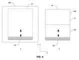
[000121] 図4aは、図2aに示したようなパターン付きエリア21を含むマスクMAの概略図である。図4bは、マスクMAの2回のスキャン露光から得られ得る基板W上の露光領域31の概略図である。マスクMAは、x方向に約104mmかつy方向に約132mm延在するパターン付きエリア21を有する従来の6インチマスクであり得る。本発明の一実施形態において、図4に示すマスクMAのスキャン露光は、x方向の約4×の縮小率およびy方向の約8×の縮小率を適用するアナモルフィック投影システムPWを用いて行われ得る。したがって、図4aに示すマスクMAのパターン付きエリア21の1回のスキャン露光は、基板W上の第1フィールド31aの露光を引き起こす。基板W上の第1フィールド31aは、x方向に約26mmかつy方向に約16.5mmに延在し得る。第1フィールド31aのy方向の範囲は、x方向およびy方向の両方に約4×の縮小率を適用する投影システムPSを有する従来のリソグラフィ装置から得られる基板W上の露光領域の(例えば、図2aに示す露光領域31)のy方向の範囲の約半分である。x方向およびy方向の両方に約4×の縮小率を適用する投影システムPSを有する従来のリソグラフィ装置から得られる基板W上の露光領域は、フルフィールド31と呼ばれ得る。第1フィールド31aは、フルフィールドの約半分の面積を有するので、第1フィールド31aは、第1ハーフフィールド31aと呼ばれ得る。
[000121] FIG. 4a is a schematic diagram of a mask MA including a patterned
[000122] 上述したとおり、第1ハーフフィールド31aは、フルフィールドのy方向の範囲の約半分のy方向の範囲を有する。フルフィールドと同等の基板Wの領域Wを露光するために、第2ハーフフィールド31bも露光され得る。第1ハーフフィールド31aおよび第2ハーフフィールド31bはともに、従来のフルフィールドと同等の寸法を有する複合露光領域31の露光を生じさせる。
[000122] As described above, the
[000123] 図5は、2つのハーフフィールド31a、31bを露光することによって形成され得る複合露光領域31の2つの実施形態の概略図である。図5aは、第1ハーフフィールド31aが第1ダイ51aと、第1ダイ51aを取り囲むスクライブライン53aと、を備える実施形態を示している。第2ハーフフィールド31bは、第2ダイ51bと、第2ダイ51bを取り囲むスクライブライン53bと、を備える。アライメントマークおよび他のフィーチャなどのパターンは、スクライブライン53aにおいて、かつ、スクライブライン53bにおいて設けられ得る。
[000123] FIG. 5 is a schematic diagram of two embodiments of a
[000124] 第1ダイ51aおよび第2ダイ51bは、互いに同一であり得る。同様に、スクライブライン53aおよびスクライブライン53bは、互いに同一であり得る。このように、一実施形態において、同一のマスクMAを使用して第1ハーフフィールド31aおよび第2ハーフフィールド31bの両方が露光され得る。一実施形態において、マスクMAは、例えば、x方向に約104mmかつy方向に約132mm延在するパターン付きエリア21を含む従来の6インチマスクであり得る。第1ハーフフィールド31aおよび第2ハーフフィールド31bは、x方向の約4×かつy方向の約8×の縮小率を適用するアナモルフィック投影システムPSを使用して露光され得る。したがって、第1ハーフフィールド31aおよび第2ハーフフィールド31bの各々は、x方向に約26mmかつy方向に約16.5mm延在し得る。
[000124] The first die 51a and the second die 51b may be identical to each other. Similarly, the scribe line 53a and the scribe line 53b may be the same as each other. Thus, in one embodiment, both the
[000125] 図5bは、第1ハーフフィールド31aがダイ51cの第1部分を備え、かつ、第2ハーフフィールド31bがダイ51cの第2部分を備える実施形態を示している。ダイ51cは、スクライブライン53cによって取り囲まれる。スクライブライン53cの第1部分は第1ハーフフィールド31aの一部として形成され、スクライブライン53cの第2部分は第2ハーフフィールド31bの一部として形成される。
[000125] FIG. 5b shows an embodiment in which the
[000126] 図5bに示す第1ハーフフィールド31aは、ダイ51cを形成するパターンの第1部分が設けられた第1マスクMAを露光することによって形成され得る。第2ハーフフィールド31bは、ダイ51cを形成するパターンの第2部分が設けられた第2マスクMAを露光することによって形成され得る。パターンの第1および第2部分は、例えば、第1ハーフフィールド31aおよび第2ハーフフィールド31bが互いに隣接する縁に沿って、互いにつながるフィーチャを含み得る。互いにつながるように第1および第2パターンのフィーチャを位置合わせする手法は、スティッチングと呼ばれ得る。互いにつながる第1および第2パターンのフィーチャは、パターンの他の部分のフィーチャのクリティカルディメンジョンを超えるクリティカルディメンジョンを有し得る。これらのフィーチャのより大きいクリティカルディメンジョンによって、2つのパターンの位置合わせにおけるエラーに対する許容値が増加し得る。これによって、集積回路または他のデバイスを正確に動作させないおそれがある第1および第2パターンのフィーチャ間の接続の失敗が起こる可能性が低減し得る。
[000126] The
[000127] 一実施形態において、露光されて図5bの複合露光領域31を形成する第1および第2マスクMAは両方とも、x方向に約104mmかつy方向に約132mm延在するパターン付きエリア21を含む従来の6インチマスクであり得る。第1ハーフフィールド31aおよび第2ハーフフィールド31bは両方とも、x方向に約4×かつy方向に約8×の縮小率を適用するアナモルフィック投影システムPSを使用して露光され得る。したがって、図5bの第1ハーフフィールド31aおよび第2ハーフフィールド31bは、x方向に約26mmかつy方向に約16.5mm延在し得る。
[000127] In one embodiment, the first and second masks MA that are exposed to form the
[000128] 特にy方向の投影システムPSの縮小率を増加させる利点を上述してきた。ただし、(例えば、5×の縮小率まで)x方向の縮小率を増加させることも有利である。特に、投影システムPSの縮小率を増加させることによって、マスクMA上の欠陥に対する、基板W上で露光されるパターンの感度が低減する。これは、従来の4×の縮小率が用いられる場合よりも欠陥のサイズが低減するからである。同様に、投影システムPSの縮小率を増加させることによって、マスク上の汚染粒子に対する、露光パターンの感度が低減する。これも、基板における汚染粒子の像のサイズが低減するからである。 [000128] In particular, the advantages of increasing the reduction ratio of the projection system PS in the y direction have been described above. However, it is also advantageous to increase the reduction rate in the x direction (eg, up to a 5 × reduction rate). In particular, by increasing the reduction ratio of the projection system PS, the sensitivity of the pattern exposed on the substrate W to defects on the mask MA is reduced. This is because the defect size is reduced compared to the case where the conventional 4 × reduction ratio is used. Similarly, by increasing the reduction ratio of the projection system PS, the sensitivity of the exposure pattern to contaminant particles on the mask is reduced. This is also because the image size of the contaminating particles on the substrate is reduced.
[000129] 加えて、基板Wにおいて受けられる放射ドーズは、投影システムPSの縮小率を増加させることによって増加する。これは、投影システムPSの縮小率を増加させることによって、所与の量の放射に露光される基板の領域のサイズが減少するからである。したがって、基板W上の単位領域当たりの放射ドーズは増加する。これは、EUV放射に露光される基板W上のパターンの領域と、EUV放射に露光されない基板W上のパターンの領域との間の、基板Wにおいて受けられる放射ドーズの差が増加するため、有利であり得る。このドーズの差は、パターンが基板Wに転写されるコントラストと呼ばれ得る。基板上のパターンのコントラストを増加させることが望ましい場合があり、これは、投影システムの縮小率を増加させることによって達成され得る。 [000129] In addition, the radiation dose received at the substrate W is increased by increasing the reduction factor of the projection system PS. This is because by increasing the reduction factor of the projection system PS, the size of the area of the substrate that is exposed to a given amount of radiation is reduced. Therefore, the radiation dose per unit area on the substrate W increases. This is advantageous because it increases the difference in radiation dose received at the substrate W between areas of the pattern on the substrate W that are exposed to EUV radiation and areas of the pattern on the substrate W that are not exposed to EUV radiation. It can be. This dose difference can be referred to as the contrast at which the pattern is transferred to the substrate W. It may be desirable to increase the contrast of the pattern on the substrate, which can be achieved by increasing the reduction ratio of the projection system.
[000130] したがって、一般に、x方向およびy方向の両方に縮小率を増加させることに起因する利点が存在する。ただし、マスクMA上の所与のパターン付きエリア21について、投影システムPSの縮小率の増加によって、パターン付きエリア21の1回のスキャン露光によって基板W上にパターン形成される露光フィールドの縮小が引き起こされることが明らかである。基板Wの所与の露光領域を露光することが望ましい場合がある。したがって、マスクMAの1回のスキャン露光に起因する露光フィールドの減少によって、基板Wの所与の露光領域を露光するために行われる必要があるスキャン露光の回数が増加し得る。行われる必要があるスキャン露光の回数の増加によって、リソグラフィ装置LAのスループットの望ましくない減少が引き起こされ得る。
[000130] Accordingly, there is generally an advantage resulting from increasing the reduction ratio in both the x and y directions. However, for a given patterned
[000131] 図5aおよび図5bを参照して上述した実施形態において、y方向の縮小率の増加(4×から8×)は、露光領域31を露光するために2回のスキャン露光が必要とされることを意味する。したがって、これによって、リソグラフィ装置のスループットの低下が生じ得る。ただし、y方向の達成可能なクリティカルディメンジョンの対応する減少は、スループットのそのような低下が正当化される程度に十分に有利であり得る。
[000131] In the embodiment described above with reference to FIGS. 5a and 5b, the increase in the reduction ratio in the y direction (4 × to 8 ×) requires two scan exposures to expose the
[000132] 上述の実施形態において、アナモルフィック投影システムPSの使用によって、y方向の縮小率がx方向の縮小率を超えるように増加することが可能になることが明らかである。これによって、リソグラフィ装置のスループットの付随する低下を制限しながら達成可能なクリティカルディメンジョンを低下させることが可能になる。例えば、x方向の4×の縮小率を維持することによって、フルフィールド31とx方向に同一の範囲を有するハーフフィールド31a、31bを露光することが可能になる。これは、フルフィールド31を露光するために2回のスキャン露光しか必要とされないことを意味する。対照的に、x方向の縮小率も8×まで増加した場合、フルフィールド31を露光するために4回のスキャン露光が必要とされることになり、したがって、スループットのより大きい低下が生じることになる。
[000132] In the above-described embodiments, it is clear that the use of the anamorphic projection system PS allows the reduction rate in the y direction to increase beyond the reduction rate in the x direction. This makes it possible to reduce the achievable critical dimension while limiting the concomitant reduction in the throughput of the lithographic apparatus. For example, by maintaining a 4 × reduction ratio in the x direction, it is possible to expose the
[000133] 投影システムPSの縮小率を増加させながらリソグラフィ装置のスループットの低下を制限する1つの可能な方法は、マスクMAのサイズを大きくすることである。しかし、従来の6インチマスクを製造し、使用するために準備された十分なインフラが存在する。したがって、リソグラフィ装置が6インチマスクを使用することが可能であることが有利であり得る。しかし、例えば図2aおよび図4aから、6インチマスクMA上の従来のパターン付きエリア21(x方向に約104mmかつy方向に約132mm延在する)によって、パターン付きエリア21によって占有されないマスクMAの実質的な部分が残ることが明らかである。
[000133] One possible way to limit the reduction of the throughput of the lithographic apparatus while increasing the reduction ratio of the projection system PS is to increase the size of the mask MA. However, there is sufficient infrastructure prepared to make and use conventional 6 inch masks. It may therefore be advantageous for the lithographic apparatus to be able to use a 6 inch mask. However, from FIGS. 2a and 4a, for example, a conventional patterned
[000134] パターン付きエリア21によって占有されないマスクMAの一部は、基板Wが露光される放射ビームにパターン形成すること以外の目的のために必要とされ得る。例えば、パターン付きエリア21の外側のマスクMAの一部は、マスクMAをサポート構造MT上で適所に保持するために必要とされ得る。パターン付きエリア21の外側のマスクMAの他の部分には、マスクMAを位置合わせするために使用されるアライメントマークが設けられ得る。しかし、上述のものなどの他の目的のために使用され得るマスクMAの一部を依然として設けながらマスクMAのパターン付きエリア21を拡張する可能性が残っている。
[000134] The portion of the mask MA that is not occupied by the patterned
[000135] 図6は、パターン付きエリア21を収容し得る領域22を含む6インチマスクの概略図である。パターン付きエリア21を収容し得る領域22は、品質エリア22と呼ばれ得る。品質エリア22は、x方向に約132mmかつy方向に約132mm延在し得る。品質エリア22は、図6に示すように丸みをつけたコーナ25を有する。丸みをつけたコーナ25は、例えば、各々が約14mmの半径を有し得る。あるいは、丸みをつけたコーナ25は、各々が14mm未満の半径を有し得る。品質エリア22は、マスクMAによって収容され得るパターン付きエリアのサイズを制限する。品質エリアの外側でマスクの平坦性およびマスクに塗布される被覆の被覆均一性は、パターン付きエリアとしてのマスクの該当部分を使用するのに十分でなくてよい。
FIG. 6 is a schematic diagram of a 6 inch mask including a
[000136] 図6には品質エリア22内に配置され得るパターン付きエリアの3つの例も示されている。従来のパターン付きエリア21が図6に示され、例えば、約104mmのx方向の範囲および約132mmのy方向の範囲を有し得る。従来のパターン付きエリア21のスキャン露光は、x方向の約4×およびy方向の約8×の縮小率を有するアナモルフィック投影システムPSを用いて行われ得る。これは、上述のとおり、基板W上のハーフフィールドの露光(すなわち、約26mmのx方向の範囲および約16.5mmのy方向の範囲を有する露光フィールド)を引き起こす。
FIG. 6 also shows three examples of areas with patterns that can be arranged in the
[000137] 図6には従来のパターン付きエリア21のx方向の範囲を超えるx方向の範囲を有する第2パターン付きエリア21aを有するマスクの実施形態も示されている。ただし、品質エリア22の丸みをつけたコーナ25に起因して、第2パターン付きエリア21aのy方向の範囲は、従来のパターン付きエリア21と比較して低減する。好ましい実施形態において、第2パターン付きエリア21aは、約124mmのx方向の範囲および約124mmのy方向の範囲を有する。第2パターン付きエリア21aのスキャン露光は、x方向の約4.8×かつy方向の約7.5×の縮小率を有するアナモルフィック投影システムPSを有するリソグラフィシステムを用いて行われ得る。これは、基板W上のハーフフィールドの露光を引き起こす。
FIG. 6 also shows an embodiment of a mask having a second patterned area 21 a having a range in the x direction that exceeds the range in the x direction of the conventional patterned
[000138] 図6には従来のパターン付きエリア21および第2パターン付きエリア21aのx方向の範囲を超えるx方向の範囲を有する第3パターン付きエリア21bも示されている。しかし、品質エリア22の丸みをつけたコーナ25に起因して、第3パターン付きエリア21bのy方向の範囲は、従来のパターン付きエリア21および第2パターン付きエリア21aの両方と比較して低減する。第3パターン付きエリア21bは、例えば、約132mmのx方向の範囲および約104mmのy方向の範囲を有し得る。第3パターン付きエリア21bのスキャン露光は、x方向の約5.1×かつy方向の約6.3×の縮小率を有するアナモルフィック投影システムPSを用いて行われ得る。これは、基板W上のハーフフィールドの露光を引き起こす。必要に応じて、リソグラフィ装置の照明システムILは、露光スリットがx方向に約132mmにわたって延在するのを可能にするために改良され得る。
[000138] FIG. 6 also shows a third patterned area 21b having a range in the x direction that exceeds the range in the x direction of the conventional patterned
[000139] 図6に示す第2および第3パターン付きエリア21a、21bの両方は、従来のパターン付きエリア21のx方向の範囲を超えるx方向の範囲を有する。従来のパターン付きエリア21のx方向の範囲を超えるx方向の範囲を有するパターン付きエリア21a、21bによって、投影システムPSの縮小率がy方向だけでなくx方向にも増加することが可能になる。パターン付きエリア21a、21bの範囲および投影システムPSの縮小率は、マスクMA上のパターン付きエリア21a、21bの露光が基板W上のハーフフィールドの露光を引き起こすように構成され得る。例えば、パターン付きエリア21a、21bの露光は、基板W上のハーフフィールドを露光するためにx方向の4×を超える縮小率を有するアナモルフィック投影システムPSを必要とし得る。従来のパターン付きエリア21のx方向の範囲を超えるx方向の範囲を有するパターン付きエリア21a、21bは、例えば、図4および図5に示すハーフフィールド31a、31bを露光するために4×を超えるx方向の縮小率を有するアナモルフィック投影システムを用いて使用され得る。
[000139] Both the second and third patterned areas 21a and 21b shown in FIG. 6 have an x-direction range that exceeds the x-direction range of the conventional patterned
[000140] 4×を超えるx方向の縮小率を有するアナモルフィック投影システムPSを使用することは、投影システムPSの縮小率を増加させることによってマスクに対する欠陥の影響が低減し、かつ、マスクに対する汚染粒子の影響が低減するため、有利である。アナモルフィック投影システムPSのx方向の縮小率を増加させることによって、基板W上にパターン形成されるフィーチャのx方向のコントラストも有利に増加する。アナモルフィック投影システムは、例えば、4.5×を超えるX方向の縮小率を有し得る。 [000140] Using an anamorphic projection system PS having a reduction ratio in the x-direction greater than 4x reduces the effect of defects on the mask by increasing the reduction ratio of the projection system PS and This is advantageous because the effect of contaminating particles is reduced. By increasing the reduction factor in the x direction of the anamorphic projection system PS, the contrast in the x direction of features patterned on the substrate W is also advantageously increased. An anamorphic projection system may have a reduction ratio in the X direction that exceeds 4.5 ×, for example.
[000141] 図6に関連して上述した第2および第3パターン付きエリア21a、21bの例から、品質エリア22の丸みをつけたコーナ25は、パターン付きエリアが品質エリア22の内側に適合することを確実にするように、x方向のパターン付きエリアの範囲の増加によってy方向のパターン付きエリアの範囲の減少が必要となり得ることを意味することが明らかである。上述のとおり、マスクMA上のパターン付きエリアの露光が基板W上のハーフフィールドの露光を引き起こすことが望ましい場合がある。したがって、パターン付きエリアのx方向の範囲の増加によって、x方向の縮小率が増加することが有利に可能になり得る。ただし、これによって、パターン付きエリアのy方向の範囲の減少が必要となることがあり、ひいては、(8×のy方向の縮小率に対する)y方向の縮小率の減少が必要となり得る。一般に、y方向の縮小率は、約6×を超えることがある。
[000141] From the example of the second and third patterned areas 21a and 21b described above with reference to FIG. 6, the
[000142] マスクMA上のパターン付きエリアのxおよびy方向の範囲およびアナモルフィック投影システムPSのxおよびy方向の縮小率は、xおよびy方向のアナモルフィック投影システムPSの縮小率を増加および減少させる相対的な利点および不利点のバランスに応じて選択され得る。そのような選択において考慮されるパラメータは、コントラスト、マスクエラー係数、および欠陥印刷適性閾値のうちの少なくとも1つを含み得る。リソグラフィプロセスの欠陥印刷適性閾値は、マスクのパターンにおける欠陥のサイズの閾値として定義され、該閾値未満ではそのような欠陥は基板上に結像されない。例えば、第2パターン付きエリア21aを従来のパターン付きエリア21と比較すると、第2パターン付きエリアの使用は、(8×の縮小率から始まり)約6%のy方向の縮小率の低下につながる。これによって、基板W上のパターンのコントラストの約6%の低下が生じる。ただし、x方向の縮小率およびコントラストは、(4×の縮小率から始まり)約20%増加する。x方向の縮小率の20%の増加は、マスクMA上のパターンにおける欠陥およびマスク上の汚染粒子に対する基板W上のパターンの感度がx方向に約20%低下することを意味する。従来のパターン付きエリア21と比較したy方向の第2パターン付きエリア21aの範囲の減少は、露光スリット23がスキャン露光中にスキャンされる長さが低減することを意味する。これによって、リソグラフィ装置のスループットの増加につながり得るパターン付きエリアの1回のスキャン露光を行うために必要な時間の量が低減し得る。
[000142] The x and y direction extent of the patterned area on the mask MA and the reduction rate of the anamorphic projection system PS in the x and y directions increase the reduction rate of the anamorphic projection system PS in the x and y directions And can be selected according to the balance of relative advantages and disadvantages to be reduced. Parameters considered in such selection may include at least one of contrast, mask error coefficient, and defect printability threshold. A defect printability threshold for a lithographic process is defined as a threshold for the size of a defect in the pattern of the mask below which no such defect is imaged on the substrate. For example, comparing the area with the second pattern 21a with the area with the
[000143] 第2パターン付きエリア21bのさらなる利点は、第2パターン付きエリア21aの総面積が従来のパターン付きエリア21の面積より約12%大きいことである。これは、パターン付きエリアのスキャン露光中、同一の量のEUV放射が、従来のパターン付きエリア21と比較して第2パターン付きエリア21aの露光中により大きい面積に対して分散されることを意味する。したがって、EUV放射への露光に起因するマスクMAの加熱は、第2パターン付きエリア21aの場合に低減する。これは、マスクMAの加熱によって、マスクMA上のパターンの歪みを生じさせ得るマスクMAの望ましくない膨張が生じ得るので、有利であり得る。
[000143] A further advantage of the second patterned area 21b is that the total area of the second patterned area 21a is approximately 12% larger than the area of the conventional patterned
[000144] パターン付きエリア21、21a、21bの具体的な実施形態および対応する縮小率の値を上述してきた。しかし、これらの実施形態に関連した説明した利点は、上述したパターン付きエリアの具体的な寸法および縮小率の値に限定されないことを理解されたい。例えば、別の実施形態において、リソグラフィシステムは、xの約4.4×の縮小率およびyの約7.9×の縮小率を有するアナモルフィック投影システムPSを有し得る。この実施形態において、第2パターン付きエリア21aは、約114mmのx方向の範囲および約130mmのy方向の範囲を有する。さらなる実施形態において、リソグラフィシステムは、xの約5.1×の縮小率およびyの約6.3×の縮小率を有するアナモルフィック投影システムPSを有し得る。この実施形態において、第2パターン付きエリア21aは、約132mmのx方向の範囲および約104mmのy方向の範囲を有する。一般に、y方向(スキャン方向)に約132mm以下、かつx方向に少なくとも104mm程度以上延在するマスクMAのパターン付きエリア21に対して放射の露光スリットをスキャンすることによって、基板W上の露光領域を露光することが有利である。
[000144] Specific embodiments of the patterned
[000145] 一般に、アナモルフィック投影システムPSは、4×以上のx方向の縮小率を有し得る。例えば、アナモルフィック投影システムPSは、4.5×を超える、4.8×を超える、または5×以上のx方向の縮小率を有し得る。アナモルフィック投影システムPSは、6×を超えるy方向の縮小率を有し得る。例えば、アナモルフィック投影システムPSは、6.5×を超える、7×を超える、または7.5×を超えるy方向の縮小率を有し得る。 [000145] In general, the anamorphic projection system PS may have a reduction ratio in the x direction of 4x or more. For example, the anamorphic projection system PS may have a reduction ratio in the x direction of greater than 4.5 ×, greater than 4.8 ×, or greater than 5 ×. The anamorphic projection system PS may have a reduction ratio in the y direction that exceeds 6 ×. For example, the anamorphic projection system PS may have a reduction ratio in the y direction of greater than 6.5 ×, greater than 7 ×, or greater than 7.5 ×.
[000146] マスクのパターン付きエリア21の範囲をy方向に約132mm以下に制限することによって、パターン付きエリア21が6インチマスクMA上に適合することが可能になる。x方向に少なくとも104mm延在するマスクMAのパターン付きエリア21を設けることによって、基板W上の露光領域が従来のフル露光フィールドのx方向の範囲以上のx方向の範囲を有することが可能になる。
[000146] By limiting the range of the patterned
[000147] xおよびy方向のパターン付きエリアの範囲は、パターン付きエリアが6インチマスクの品質エリア22の内側で適合することを確実にしながら、露光プロセスの要件に応じて調整され得る。パターン付きエリアのx方向の範囲および投影システムのx方向の縮小率が、基板上の露光領域のx方向の範囲が約26mmである程度であることが望ましい場合がある。さらに、パターン付きエリアのy方向の範囲および投影システムのy方向の縮小率が、基板上の露光領域のy方向の範囲が約16.5mmである程度であることが望ましい場合があり、したがって、基板上の露光領域は、ハーフフィールドの寸法を有する。
[000147] The extent of the patterned area in the x and y directions can be adjusted according to the requirements of the exposure process, ensuring that the patterned area fits inside the
[000148] x方向の縮小率は、従来のフル露光フィールドのx方向の範囲以上のx方向の範囲を有する基板W上の露光領域を依然として形成しながら、5×程度にまで増加し得る。これは、6インチマスク上のパターン付きエリア21をx方向に拡張することによって達成され得る。例えば、パターン付きエリア21は、最大約132mmのx方向の範囲を有し得る。パターン付きエリア21は、約132mmのx方向の範囲および約132mmのy方向の範囲を有するマスクMAの品質エリア22内に適合し得る。品質エリア22は、丸みをつけたコーナ25を有し得る。丸みをつけたコーナ25は、各々が約14mm以下の半径を有し得る。
[000148] The reduction ratio in the x direction can increase to as much as 5 × while still forming an exposure region on the substrate W having a range in the x direction that is greater than the range in the x direction of a conventional full exposure field. This can be achieved by extending the patterned
[000149] x方向の縮小率を超えるy方向の縮小率で、マスクMAから基板の露光領域上に反射される放射の露光スリット23を投影することが有利である。達成可能なy方向のクリティカルディメンジョンは、放射がマスクMAに入射する主光線角度θの影響によって制限される。したがって、y方向の縮小率を増加させることは、達成可能なクリティカルディメンジョンを低減させる際に特に有利である。また、x方向の縮小率を増加させることに関連する利点が存在するが、従来のフル露光フィールドのx方向の範囲と同等のx方向の範囲を有する基板w上の露光領域を形成することも有利である。これによって、従来のフル露光フィールドがたった2回のスキャン露光で露光されることが可能になり、したがって縮小率の増加に起因し得るリソグラフィ装置のスループットの低下が制限される。 [000149] It is advantageous to project the exposure slit 23 of radiation reflected from the mask MA onto the exposure area of the substrate with a reduction ratio in the y direction that exceeds the reduction ratio in the x direction. The achievable critical dimension in the y direction is limited by the influence of the chief ray angle θ at which the radiation is incident on the mask MA. Therefore, increasing the reduction rate in the y direction is particularly advantageous in reducing the achievable critical dimension. Also, although there is an advantage associated with increasing the reduction ratio in the x direction, it is also possible to form an exposure region on the substrate w having an x direction range equivalent to the x direction range of a conventional full exposure field. It is advantageous. This allows a conventional full exposure field to be exposed with only two scan exposures, thus limiting the reduction in lithographic apparatus throughput that can result from an increased reduction ratio.
[000150] 上述の説明より、フィーチャの達成可能なクリティカルディメンジョンは、xおよびy方向で異なり得ることが明らかである。xおよびy方向の達成可能なクリティカルディメンジョンは、マスクMA上のパターン付きエリアの範囲と、xおよびy方向のアナモルフィック投影システムPSの縮小率の値とによって決まり得る。上述したようなリソグラフィプロセスを使用して製造されるデバイスの設計者は、xおよびy方向の達成可能なクリティカルディメンジョンに応じてデバイスのフィーチャを位置合わせし得る。例えば、達成可能なクリティカルディメンジョンは、x方向よりy方向において小さくなり得る。この場合、デバイスの設計者は、デバイスのフィーチャがy方向に延在する最小寸法を有するようにデバイスのフィーチャを位置合わせし得る。リソグラフィ装置を使用してデバイスを露光する場合、x方向よりy方向により小さいクリティカルディメンジョンを提供する照明モードが使用され得る。例えば、y方向に間隔をおいて配置されたポールを有するダイポールモードが使用され得る。一般に、本発明の一実施形態において、x方向の間隔を超えるy方向の間隔を有する放射を含む照明モードが使用され得る。 [000150] From the above description, it is clear that the achievable critical dimension of a feature can be different in the x and y directions. The achievable critical dimensions in the x and y directions may depend on the extent of the patterned area on the mask MA and the reduction value of the anamorphic projection system PS in the x and y directions. A designer of a device manufactured using a lithographic process as described above may align device features depending on the achievable critical dimensions in the x and y directions. For example, the achievable critical dimension can be smaller in the y direction than in the x direction. In this case, the device designer may align the device features such that the device features have a minimum dimension extending in the y direction. When exposing a device using a lithographic apparatus, an illumination mode may be used that provides a smaller critical dimension in the y direction than in the x direction. For example, a dipole mode with poles spaced in the y direction can be used. In general, in one embodiment of the present invention, an illumination mode that includes radiation having a y-direction spacing that exceeds a x-direction spacing may be used.
[000151] 上述のとおり、6インチマスクを製造し、使用するために準備された十分なインフラが存在する。したがって、リソグラフィ装置が、6インチマスクを支持するように構築されたサポート構造MTと、x方向の縮小率を超えるy方向(スキャン方向)の縮小率を有する投影システムPSと、を含むことが有利である。 [000151] As mentioned above, there is sufficient infrastructure prepared to make and use 6 inch masks. Accordingly, it is advantageous that the lithographic apparatus includes a support structure MT configured to support a 6 inch mask and a projection system PS having a reduction ratio in the y direction (scan direction) that exceeds a reduction ratio in the x direction. It is.
[000152] ただし、リソグラフィ装置が、6インチマスクより大きいマスクMAを支持することが可能であることも有利であり得る。図7aは、6インチマスクより大きい拡張マスクMA’の概略図である。特に、拡張マスクMA’は、6インチを超えるy方向の範囲を有する。例えば、拡張マスクMA’は、従来の6インチマスクMAのy方向の範囲の約2倍のy方向の範囲を有し得る。拡張マスクMA’は、従来の6インチマスクMA上に適合するパターン付きエリア21の範囲を超える範囲を有する拡張パターン付きエリア21’を含む。例えば、拡張パターン付きエリア21’は、約264mmのy方向の範囲を有してよく、したがって従来の6インチマスクMA上のパターン付きエリアの範囲の約2倍のy方向の範囲を有し得る。
[000152] However, it may also be advantageous for the lithographic apparatus to be able to support a mask MA that is larger than a 6 inch mask. FIG. 7a is a schematic view of an extended mask MA 'larger than a 6 inch mask. In particular, the expansion mask MA 'has a y-direction range exceeding 6 inches. For example, the extended mask MA 'may have a y-direction range that is approximately twice that of the conventional 6-inch mask MA. The extended mask MA 'includes an extended patterned area 21' having a range that exceeds the range of the patterned
[000153] 従来の6インチマスク上のパターン付きエリア21を超える範囲を有するようにパターン付きエリア21’の範囲を増加させることによって、基板W上に形成される露光領域31の範囲が増加する。図7bは、図7aに示す拡張マスクMA’のスキャン露光中、基板w上に形成される露光領域31の概略図である。露光領域31は、約8×のy方向の縮小率を有するアナモルフィック投影システムPSを使用して形成され得る。図7から、マスクMA上の拡張パターン付きエリア21’によって、1回のスキャン露光および8×のy方向の縮小率でフル露光フィールド31を露光することが可能になることが分かる。フルフィールド31は、例えば、従来のフルフィールドの寸法(例えば、約26mmのy方向の範囲および約33mmのx方向の範囲)を有し得る。
[000153] The range of the
[000154] 拡張マスクMA’を使用して1回のスキャン露光でフルフィールド31を露光することによって、アナモルフィック投影システムPSを内蔵するリソグラフィ装置のスループットが増加することが可能になり得る。露光スリット23は、従来のリソグラフィ装置における通常の速度より速い速度で拡張パターン付きエリア21’に対してスキャンされ得る。例えば、スキャン速度は、従来のリソグラフィ装置と比較して、約2倍増加し得る。これによって、従来のパターン付きエリア21を露光するのとほぼ同一の時間で拡張パターン付きエリア21’を露光することが可能になり得る。
[000154] By exposing the
[000155] 一実施形態において、拡張パターン付きエリア21’のx方向の範囲は、約104mmであり得る。この実施形態において、図7bに示すフル露光フィールド31は、約4×のx方向の縮小率を有する投影システムPSを使用して、1回のスキャン露光で露光され得る。
[000155] In one embodiment, the extent of the extended pattern area 21 'in the x direction may be about 104 mm. In this embodiment, the
[000156] 別の実施形態において、拡張パターン付きエリア21’のx方向の範囲は、104mmを超えることがある。例えば、一実施形態において、拡張パターン付きエリア21’のx方向の範囲は、約130mmであり得る。この実施形態において、図7bに示すフル露光フィールド31は、約5×のx方向の縮小率を有する投影システムPSを使用することによって、1回のスキャン露光で露光され得る。他の実施形態において、拡張パターン付きエリア21’は、104mmを超える他のx方向の範囲を有し得る。そのような拡張パターン付きエリア21’を露光するために使用されるx方向の縮小率は、基板W上の結果として得られる露光フィールド31のx方向の範囲が約26mm(すなわち、従来のフルフィールドのx方向の範囲)と実質的に同等である程度であり得る。
[000156] In another embodiment, the extent of the extended pattern area 21 'in the x direction may exceed 104 mm. For example, in one embodiment, the x-direction range of the
[000157] リソグラフィ装置は、6インチマスクMAを支持するように構成されてよく、また、拡張マスクMA’を支持するように構成されてよい。このように、同一のリソグラフィ装置を使用して、従来のパターン付きエリア21および拡張パターン付きエリア21’の両方が露光され得る。リソグラフィ装置は、6インチマスクMAおよび拡張マスクMAの両方を(互いに別々の時に)支持するように構成されたサポート構造MTを備え得る。あるいは、リソグラフィ装置は、6インチマスクMAを支持するように構成された少なくとも1つのサポート構造と、拡張マスクMA’を支持するように構成された少なくとも1つのサポート構造MTとを備える、交換可能なサポート構造MTを備え得る。サポート構造MTは、露光されるマスクMAに応じて、リソグラフィ装置内で交換され得る。
[000157] The lithographic apparatus may be configured to support a 6 inch mask MA and may be configured to support an extended mask MA '. In this way, both the conventional patterned
[000158] 6インチマスクMAを支持するように構成され、かつ拡張マスクMA’を支持するように構成されたリソグラフィ装置は、アナモルフィック投影システムPSをさらに備え得る。アナモルフィック投影システムPSは、約8×のy方向の縮小率および約4×のx方向の縮小率を有し得る。あるいは、アナモルフィック投影システムPSは、4×を超えるx方向の縮小率を有し得る。例えば、アナモルフィック投影システムPSは、4.5×を超える、4.8×を超える、または5×以上のx方向の縮小率を有し得る。アナモルフィック投影システムPSは、8×未満のy方向の縮小率を有し得る。例えば、アナモルフィック投影システムは、7.5×程度のy方向の縮小率または6.3×程度のy方向の縮小率を有し得る。一般に、アナモルフィック投影システムPSは、6×を超えるy方向の縮小率を有し得る。 [000158] The lithographic apparatus configured to support the 6 inch mask MA and configured to support the extended mask MA 'may further comprise an anamorphic projection system PS. The anamorphic projection system PS may have a reduction ratio in the y direction of about 8 × and a reduction ratio in the x direction of about 4 ×. Alternatively, the anamorphic projection system PS may have a reduction ratio in the x direction that is greater than 4 ×. For example, the anamorphic projection system PS may have a reduction ratio in the x direction of greater than 4.5 ×, greater than 4.8 ×, or greater than 5 ×. The anamorphic projection system PS may have a y-direction reduction factor of less than 8 ×. For example, an anamorphic projection system may have a reduction ratio in the y direction on the order of 7.5 × or a reduction ratio in the y direction on the order of 6.3 ×. In general, the anamorphic projection system PS may have a reduction ratio in the y direction that exceeds 6 ×.
[000159] 同一のアナモルフィック投影システムPSは、6インチマスクMAおよび拡張マスクMA’の露光中に使用され得る。基板W上の結果として得られる露光領域31の範囲は、露光されるマスクMAのサイズ、特に、マスクMA上のパターン付きエリア21のサイズによって決まることになる。
[000159] The same anamorphic projection system PS may be used during exposure of the 6 inch mask MA and the extended mask MA '. The range of the resulting
[000160] 6インチマスクMAを支持するように構成され、かつ、拡張マスクMA’を支持するように構成されたリソグラフィ装置は、リソグラフィ装置のユーザに対してより高い柔軟性を提供し得る。y方向のリソグラフィ装置の縮小率の増加によって、従来のリソグラフィ装置と比較して、達成可能なクリティカルディメンジョンの減少が促進され得る。リソグラフィ装置は、リソグラフィ装置のスループットの低下がほとんどまたは全くない拡張マスクMA’を露光するために使用され得る。リソグラフィ装置は、6インチマスクMAを露光するためにも使用されてよく、したがって6インチマスクを製造し、使用するために準備された十分なインフラとの適合性を提供する。 [000160] A lithographic apparatus configured to support a 6 inch mask MA and configured to support an extended mask MA 'may provide greater flexibility to a user of the lithographic apparatus. An increase in the reduction ratio of the lithographic apparatus in the y direction may facilitate a reduction in the achievable critical dimension compared to a conventional lithographic apparatus. The lithographic apparatus can be used to expose an extended mask MA 'that has little or no decrease in throughput of the lithographic apparatus. The lithographic apparatus may also be used to expose a 6 inch mask MA, thus providing compatibility with sufficient infrastructure prepared to make and use the 6 inch mask.
[000161] 集積回路などのデバイスの製造において、集積回路または他のデバイスの第1機能層を小さいクリティカルディメンジョンで設けること、および、該デバイスの後続の層をより大きいクリティカルディメンジョンで設けることは通常のことである。したがって、上述したようなアナモルフィック投影システムPSを備えるEUVリソグラフィ装置は、基板W上の第1機能層を小さいクリティカルディメンジョンでパターン形成するために使用され得る。そして、基板Wは、より大きいクリティカルディメンジョンを有する後続の層をパターン形成するために、1つ以上の他のリソグラフィ装置に搬送され得る。該1つ以上の他のリソグラフィ装置は、従来のEUVリソグラフィ装置(例えば、x方向およびy方向の両方で4×の縮小率を有する)を含んでよく、また、EUV放射を使用しないリソグラフィ装置(例えば、DUVリソグラフィ装置)を含んでよい。 [000161] In the manufacture of devices such as integrated circuits, it is common to provide the first functional layer of an integrated circuit or other device with a small critical dimension and to provide subsequent layers of the device with a larger critical dimension. That is. Thus, an EUV lithographic apparatus comprising an anamorphic projection system PS as described above can be used to pattern the first functional layer on the substrate W with a small critical dimension. The substrate W can then be transported to one or more other lithographic apparatus to pattern subsequent layers having larger critical dimensions. The one or more other lithographic apparatus may include a conventional EUV lithographic apparatus (eg, having a 4 × reduction ratio in both the x and y directions) and a lithographic apparatus that does not use EUV radiation ( For example, a DUV lithographic apparatus) may be included.
[000162] リソグラフィ装置のアナモルフィック投影システムがUS20130128252号に開示されている。本発明の実施形態は、当該投影システムから改良された投影システムを使用し得る。投影システムおよびそのような投影システムを備えるリソグラフィ装置は、4×、4.4×、4.5×、4.8×、5×、および5.1×のxの縮小係数を有すると言及されてきた。投影システムおよびそのような投影システムを備えるリソグラフィ装置は、6.3×、7.5×、7.9×、および8×のyの縮小係数を有すると言及されてきた。これらの縮小係数の値は近似値であり、また、投影システムの縮小率の調整を使用中に(例えば、リソグラフィ装置の許容値に対応するために)行うことが可能であり得ることを理解されたい。 [000162] An anamorphic projection system of a lithographic apparatus is disclosed in US20130128252. Embodiments of the present invention may use an improved projection system from the projection system. Projection system and lithographic apparatus comprising such a projection system are referred to as having a reduction factor of x of 4 ×, 4.4 ×, 4.5 ×, 4.8 ×, 5 ×, and 5.1 ×. I came. Projection systems and lithographic apparatus comprising such projection systems have been referred to as having y reduction factors of 6.3 ×, 7.5 ×, 7.9 ×, and 8 ×. It is understood that these reduction factor values are approximations, and that adjustment of the reduction ratio of the projection system may be possible during use (eg, to accommodate lithographic apparatus tolerances). I want.
[000163] 本明細書において、リソグラフィ装置の関連での本発明の実施形態について具体的な言及がなされているが、本発明の実施形態は、他の装置で使用されてよい。本発明の実施形態は、マスク検査装置、メトロロジ装置、またはウェーハ(または他の基板)やマスク(または他のパターニングデバイス)などのオブジェクトを測定または処理するあらゆる装置の一部を形成し得る。これらの装置は、通常リソグラフィツールとして呼ばれ得る。そのようなリソグラフィツールは、真空条件または環境(非真空)条件を使用し得る。 [000163] Although specific references are made herein to embodiments of the present invention in the context of a lithographic apparatus, the embodiments of the present invention may be used with other apparatuses. Embodiments of the present invention may form part of a mask inspection apparatus, metrology apparatus, or any apparatus that measures or processes objects such as wafers (or other substrates) or masks (or other patterning devices). These apparatuses can usually be referred to as lithography tools. Such lithography tools may use vacuum conditions or environmental (non-vacuum) conditions.
[000164] 「EUV放射」という用語は、4〜20nmの範囲、例えば、13〜14nmの範囲の波長を有する電磁放射を包含するとみなされてよい。EUV放射は、10nm未満、例えば、6.7nmや6.8nmなどの4〜10nmの範囲内の波長を有し得る。 [000164] The term "EUV radiation" may be considered to encompass electromagnetic radiation having a wavelength in the range of 4-20 nm, for example in the range of 13-14 nm. EUV radiation may have a wavelength of less than 10 nm, for example in the range of 4-10 nm, such as 6.7 nm or 6.8 nm.
[00016] 本明細書において、IC製造におけるリソグラフィ装置の使用について具体的な言及がなされているが、本明細書記載のリソグラフィ装置が、他の用途を有し得ることが理解されるべきである。他の可能な用途には、集積光学システム、磁気ドメインメモリ用のガイダンスパターンおよび検出パターン、フラットパネルディスプレイ、液晶ディスプレイ(LCD)、薄膜磁気ヘッド等の製造が含まれる。 [00016] Although specific reference is made herein to the use of a lithographic apparatus in IC manufacture, it should be understood that the lithographic apparatus described herein may have other uses. . Other possible applications include the manufacture of integrated optical systems, guidance and detection patterns for magnetic domain memories, flat panel displays, liquid crystal displays (LCDs), thin film magnetic heads and the like.
[000166] 以上、本発明の具体的な実施形態を説明してきたが、本発明は、上述以外の態様で実施できることが明らかである。上記の説明は、制限ではなく例示を意図したものである。したがって、当業者には明らかなように、添付の特許請求の範囲を逸脱することなく本記載の発明に変更を加えてもよい。 [000166] While specific embodiments of the invention have been described above, it will be appreciated that the invention may be practiced otherwise than as described. The above description is intended to be illustrative rather than limiting. Thus, it will be apparent to one skilled in the art that modifications may be made to the invention as described without departing from the scope of the claims set out below.
Claims (24)
基板を保持するとともに、スキャン方向に移動可能である基板テーブルと、
前記パターン付き放射ビームを前記基板の露光領域上に投影し、前記スキャン方向において、前記スキャン方向に垂直な第2方向における縮小率を超える縮小率を有する投影システムであって、前記第2方向における前記縮小率は4×を超える、投影システムと、
を備える、リソグラフィ装置。 A support structure that supports a mask with a patterned area capable of forming a patterned radiation beam by applying a pattern to a cross section of the radiation beam and is movable in a scanning direction;
A substrate table that holds the substrate and is movable in the scanning direction;
Projecting the patterned radiation beam onto an exposure area of the substrate and having a reduction ratio in the scan direction that exceeds a reduction ratio in a second direction perpendicular to the scan direction, A projection system wherein the reduction ratio exceeds 4 ×;
A lithographic apparatus comprising:
スキャン方向に、かつマスクのパターン付きエリアにわたって、放射の露光スリットをスキャンすることと、
前記スキャン方向において、前記スキャン方向に垂直な第2方向における縮小率を超える縮小率で、前記マスクから反射される放射の露光スリットを前記基板の前記露光領域上に投影させることであって、前記第2方向の前記縮小率は4×を超えることと、
を含む、方法。 A method of exposing an exposure area on a substrate using a lithographic apparatus, comprising:
Scanning the exposure slit of radiation in the scanning direction and across the patterned area of the mask;
Projecting an exposure slit of radiation reflected from the mask onto the exposure area of the substrate at a reduction ratio that exceeds a reduction ratio in a second direction perpendicular to the scan direction in the scan direction, The reduction ratio in the second direction exceeds 4 ×;
Including the method.
放射ビームの断面にパターンを付与してパターン付き放射ビームを形成可能であるパターン付きエリアを備え、
使用中、前記放射ビームが前記パターン付きエリアにわたってスキャンされるスキャン方向を伴って構成され、
前記パターン付きエリアは、前記スキャン方向に垂直な第2方向における104mmを超える範囲を有する、マスク。 A mask for use in a lithographic apparatus,
A patterned area capable of forming a patterned radiation beam by applying a pattern to the cross section of the radiation beam;
In use, the radiation beam is configured with a scan direction that is scanned across the patterned area;
The patterned area has a mask having a range exceeding 104 mm in a second direction perpendicular to the scanning direction.
Applications Claiming Priority (3)
| Application Number | Priority Date | Filing Date | Title |
|---|---|---|---|
| EP14156365 | 2014-02-24 | ||
| EP14156365.0 | 2014-02-24 | ||
| PCT/EP2015/052673 WO2015124457A1 (en) | 2014-02-24 | 2015-02-10 | Lithographic apparatus and method |
Related Child Applications (1)
| Application Number | Title | Priority Date | Filing Date |
|---|---|---|---|
| JP2019220832A Division JP2020046680A (en) | 2014-02-24 | 2019-12-06 | Lithographic apparatus and method |
Publications (1)
| Publication Number | Publication Date |
|---|---|
| JP2017506358A true JP2017506358A (en) | 2017-03-02 |
Family
ID=50151200
Family Applications (2)
| Application Number | Title | Priority Date | Filing Date |
|---|---|---|---|
| JP2016545280A Pending JP2017506358A (en) | 2014-02-24 | 2015-02-10 | Lithographic apparatus and method |
| JP2019220832A Pending JP2020046680A (en) | 2014-02-24 | 2019-12-06 | Lithographic apparatus and method |
Family Applications After (1)
| Application Number | Title | Priority Date | Filing Date |
|---|---|---|---|
| JP2019220832A Pending JP2020046680A (en) | 2014-02-24 | 2019-12-06 | Lithographic apparatus and method |
Country Status (7)
| Country | Link |
|---|---|
| US (1) | US10558126B2 (en) |
| JP (2) | JP2017506358A (en) |
| KR (1) | KR102340171B1 (en) |
| CN (1) | CN106062635B (en) |
| NL (1) | NL2014267A (en) |
| TW (2) | TWI663480B (en) |
| WO (1) | WO2015124457A1 (en) |
Families Citing this family (5)
| Publication number | Priority date | Publication date | Assignee | Title |
|---|---|---|---|---|
| JP6582971B2 (en) * | 2015-12-25 | 2019-10-02 | Agc株式会社 | Mask blank substrate and method for manufacturing the same |
| KR102374206B1 (en) | 2017-12-05 | 2022-03-14 | 삼성전자주식회사 | Method of fabricating semiconductor device |
| US10665455B2 (en) | 2018-10-22 | 2020-05-26 | Taiwan Semiconductor Manufacturing Co., Ltd. | Method (and related apparatus) that reduces cycle time for forming large field integrated circuits |
| TWI683346B (en) * | 2018-10-22 | 2020-01-21 | 台灣積體電路製造股份有限公司 | Integrated circuit and method for forming integrated circuit |
| DE102019205271A1 (en) * | 2019-04-11 | 2020-10-15 | Carl Zeiss Smt Gmbh | Imaging optics for imaging an object field in an image field as well as projection exposure system with such imaging optics |
Citations (11)
| Publication number | Priority date | Publication date | Assignee | Title |
|---|---|---|---|---|
| JP2004031808A (en) * | 2002-06-27 | 2004-01-29 | Nikon Corp | Projection optical system of aligner, aligner equipped with the same, and method for exposure using the aligner |
| JP2004214242A (en) * | 2002-12-27 | 2004-07-29 | Canon Inc | Reflection-type projection optical system, aligner and device manufacturing method |
| JP2006126816A (en) * | 2004-09-29 | 2006-05-18 | Hoya Corp | Mask blank substrate, mask blank, exposure mask, method for manufacturing semiconductor device and method for manufacturing mask blank substrate |
| JP2008176326A (en) * | 2007-01-17 | 2008-07-31 | Carl Zeiss Smt Ag | Imaging optical system |
| JP2009124139A (en) * | 2007-11-09 | 2009-06-04 | Asml Netherlands Bv | Device manufacturing method and lithography apparatus, computer program product |
| JP2009252818A (en) * | 2008-04-02 | 2009-10-29 | Renesas Technology Corp | Reflective mask, its inspection method, and method for manufacturing semiconductor device |
| JP2011066079A (en) * | 2009-09-15 | 2011-03-31 | Toshiba Corp | Flare correction method, and method of manufacturing semiconductor device |
| JP2013050716A (en) * | 2011-08-24 | 2013-03-14 | Palo Alto Research Center Inc | Single-pass imaging system with anamorphic optical system |
| JP2013058761A (en) * | 2007-03-19 | 2013-03-28 | Nikon Corp | Holding device, exposure device, exposure method, and manufacturing method of device |
| WO2013045597A1 (en) * | 2011-09-30 | 2013-04-04 | Carl Zeiss Smt Gmbh | Imaging catoptric euv projection optical unit |
| JP2013541729A (en) * | 2010-09-15 | 2013-11-14 | カール・ツァイス・エスエムティー・ゲーエムベーハー | Imaging optics |
Family Cites Families (12)
| Publication number | Priority date | Publication date | Assignee | Title |
|---|---|---|---|---|
| EP1039511A4 (en) * | 1997-12-12 | 2005-03-02 | Nikon Corp | Projection exposure method and projection aligner |
| JP4118585B2 (en) * | 2002-04-03 | 2008-07-16 | Hoya株式会社 | Mask blank manufacturing method |
| WO2006013100A2 (en) * | 2004-08-06 | 2006-02-09 | Carl Zeiss Smt Ag | Projection objective for microlithography |
| KR100710960B1 (en) | 2004-09-29 | 2007-04-24 | 호야 가부시키가이샤 | Mask blank substrate, mask blank, exposure mask, mask blank substrate manufacturing method, and semiconductor manufacturing method |
| KR101127346B1 (en) * | 2005-09-13 | 2012-03-29 | 칼 짜이스 에스엠티 게엠베하 | Microlithography projection optical system, method for manufacturing a device and method to design an optical surface |
| US7920338B2 (en) * | 2006-03-28 | 2011-04-05 | Carl Zeiss Smt Gmbh | Reduction projection objective and projection exposure apparatus including the same |
| JP2010107596A (en) * | 2008-10-28 | 2010-05-13 | Canon Inc | Reflection type projection optical system, exposure device, and method of manufacturing device |
| WO2010061725A1 (en) * | 2008-11-27 | 2010-06-03 | Hoya株式会社 | Substrate with multilayer reflection film, reflective mask blank and method for manufacturing reflective mask blank |
| DE102009047179B8 (en) * | 2009-11-26 | 2016-08-18 | Carl Zeiss Smt Gmbh | projection lens |
| CN104136998B (en) * | 2011-12-28 | 2016-08-24 | 卡尔蔡司Smt有限责任公司 | Mask and scanning projection exposure method for micro-lithography |
| KR20150058455A (en) * | 2012-09-21 | 2015-05-28 | 에이에스엠엘 네델란즈 비.브이. | Lithographic method and apparatus |
| DE102014208770A1 (en) * | 2013-07-29 | 2015-01-29 | Carl Zeiss Smt Gmbh | Projection optics for imaging an object field in an image field and projection exposure apparatus with such a projection optics |
-
2015
- 2015-02-10 JP JP2016545280A patent/JP2017506358A/en active Pending
- 2015-02-10 US US15/120,093 patent/US10558126B2/en active Active
- 2015-02-10 WO PCT/EP2015/052673 patent/WO2015124457A1/en active Application Filing
- 2015-02-10 CN CN201580010021.4A patent/CN106062635B/en active Active
- 2015-02-10 NL NL2014267A patent/NL2014267A/en unknown
- 2015-02-10 KR KR1020167026367A patent/KR102340171B1/en active IP Right Grant
- 2015-02-17 TW TW104105709A patent/TWI663480B/en active
- 2015-02-17 TW TW108110094A patent/TWI707208B/en active
-
2019
- 2019-12-06 JP JP2019220832A patent/JP2020046680A/en active Pending
Patent Citations (11)
| Publication number | Priority date | Publication date | Assignee | Title |
|---|---|---|---|---|
| JP2004031808A (en) * | 2002-06-27 | 2004-01-29 | Nikon Corp | Projection optical system of aligner, aligner equipped with the same, and method for exposure using the aligner |
| JP2004214242A (en) * | 2002-12-27 | 2004-07-29 | Canon Inc | Reflection-type projection optical system, aligner and device manufacturing method |
| JP2006126816A (en) * | 2004-09-29 | 2006-05-18 | Hoya Corp | Mask blank substrate, mask blank, exposure mask, method for manufacturing semiconductor device and method for manufacturing mask blank substrate |
| JP2008176326A (en) * | 2007-01-17 | 2008-07-31 | Carl Zeiss Smt Ag | Imaging optical system |
| JP2013058761A (en) * | 2007-03-19 | 2013-03-28 | Nikon Corp | Holding device, exposure device, exposure method, and manufacturing method of device |
| JP2009124139A (en) * | 2007-11-09 | 2009-06-04 | Asml Netherlands Bv | Device manufacturing method and lithography apparatus, computer program product |
| JP2009252818A (en) * | 2008-04-02 | 2009-10-29 | Renesas Technology Corp | Reflective mask, its inspection method, and method for manufacturing semiconductor device |
| JP2011066079A (en) * | 2009-09-15 | 2011-03-31 | Toshiba Corp | Flare correction method, and method of manufacturing semiconductor device |
| JP2013541729A (en) * | 2010-09-15 | 2013-11-14 | カール・ツァイス・エスエムティー・ゲーエムベーハー | Imaging optics |
| JP2013050716A (en) * | 2011-08-24 | 2013-03-14 | Palo Alto Research Center Inc | Single-pass imaging system with anamorphic optical system |
| WO2013045597A1 (en) * | 2011-09-30 | 2013-04-04 | Carl Zeiss Smt Gmbh | Imaging catoptric euv projection optical unit |
Also Published As
| Publication number | Publication date |
|---|---|
| WO2015124457A8 (en) | 2016-03-31 |
| TW201535069A (en) | 2015-09-16 |
| TWI707208B (en) | 2020-10-11 |
| CN106062635A (en) | 2016-10-26 |
| US10558126B2 (en) | 2020-02-11 |
| TW201928531A (en) | 2019-07-16 |
| NL2014267A (en) | 2015-08-25 |
| KR20160125487A (en) | 2016-10-31 |
| WO2015124457A1 (en) | 2015-08-27 |
| KR102340171B1 (en) | 2021-12-16 |
| CN106062635B (en) | 2019-11-15 |
| TWI663480B (en) | 2019-06-21 |
| US20170176868A1 (en) | 2017-06-22 |
| JP2020046680A (en) | 2020-03-26 |
Similar Documents
| Publication | Publication Date | Title |
|---|---|---|
| JP2020046680A (en) | Lithographic apparatus and method | |
| TWI643243B (en) | Lithographic method and apparatus | |
| US9989863B2 (en) | Lithographic system | |
| JP6321777B6 (en) | Source collector apparatus, lithography apparatus and method | |
| JP5689461B2 (en) | Lithographic apparatus, method for controlling reflection of extreme ultraviolet light, and masking device | |
| JP4639134B2 (en) | Lithographic system and method for adjusting transmission characteristics of an optical path in a lithographic system | |
| JP5147865B2 (en) | Device manufacturing method, lithographic apparatus, and computer program | |
| JP4429267B2 (en) | Lithographic apparatus and device manufacturing method | |
| TW201329647A (en) | Reticle assembly, a lithographic apparatus, the use in a lithographic process, and a method to project two or more image fields in a single scanning movement of a lithographic process | |
| CN114641731A (en) | Method for improving uniformity of a substrate during photolithography | |
| EP4293424A1 (en) | Method of spatially aligning a patterning device and a substrate | |
| US20240353756A1 (en) | Lithographic method to enhance illuminator transmission | |
| CN116762042A (en) | Fast uniformity drift correction | |
| JP2024513034A (en) | Patterning apparatus and method for lithographic apparatus | |
| JP2024504714A (en) | Fast correction of uniformity drift |
Legal Events
| Date | Code | Title | Description |
|---|---|---|---|
| A521 | Request for written amendment filed |
Free format text: JAPANESE INTERMEDIATE CODE: A523 Effective date: 20160908 |
|
| A621 | Written request for application examination |
Free format text: JAPANESE INTERMEDIATE CODE: A621 Effective date: 20180202 |
|
| A131 | Notification of reasons for refusal |
Free format text: JAPANESE INTERMEDIATE CODE: A131 Effective date: 20190110 |
|
| A521 | Request for written amendment filed |
Free format text: JAPANESE INTERMEDIATE CODE: A523 Effective date: 20190410 |
|
| A02 | Decision of refusal |
Free format text: JAPANESE INTERMEDIATE CODE: A02 Effective date: 20190808 |
|
| A521 | Request for written amendment filed |
Free format text: JAPANESE INTERMEDIATE CODE: A523 Effective date: 20191206 |
|
| C60 | Trial request (containing other claim documents, opposition documents) |
Free format text: JAPANESE INTERMEDIATE CODE: C60 Effective date: 20191206 |
|
| C11 | Written invitation by the commissioner to file amendments |
Free format text: JAPANESE INTERMEDIATE CODE: C11 Effective date: 20191217 |
|
| A911 | Transfer to examiner for re-examination before appeal (zenchi) |
Free format text: JAPANESE INTERMEDIATE CODE: A911 Effective date: 20200204 |
|
| C21 | Notice of transfer of a case for reconsideration by examiners before appeal proceedings |
Free format text: JAPANESE INTERMEDIATE CODE: C21 Effective date: 20200205 |
|
| A912 | Re-examination (zenchi) completed and case transferred to appeal board |
Free format text: JAPANESE INTERMEDIATE CODE: A912 Effective date: 20200306 |
|
| C211 | Notice of termination of reconsideration by examiners before appeal proceedings |
Free format text: JAPANESE INTERMEDIATE CODE: C211 Effective date: 20200310 |
|
| C22 | Notice of designation (change) of administrative judge |
Free format text: JAPANESE INTERMEDIATE CODE: C22 Effective date: 20200604 |
|
| C23 | Notice of termination of proceedings |
Free format text: JAPANESE INTERMEDIATE CODE: C23 Effective date: 20200702 |
|
| C03 | Trial/appeal decision taken |
Free format text: JAPANESE INTERMEDIATE CODE: C03 Effective date: 20200730 |
|
| C30A | Notification sent |
Free format text: JAPANESE INTERMEDIATE CODE: C3012 Effective date: 20200730 |