JP2017505258A - CVT power train and method of operating a CVT power train - Google Patents
CVT power train and method of operating a CVT power train Download PDFInfo
- Publication number
- JP2017505258A JP2017505258A JP2016547917A JP2016547917A JP2017505258A JP 2017505258 A JP2017505258 A JP 2017505258A JP 2016547917 A JP2016547917 A JP 2016547917A JP 2016547917 A JP2016547917 A JP 2016547917A JP 2017505258 A JP2017505258 A JP 2017505258A
- Authority
- JP
- Japan
- Prior art keywords
- power train
- cvt
- transmission mechanism
- cvt power
- clutch
- Prior art date
- Legal status (The legal status is an assumption and is not a legal conclusion. Google has not performed a legal analysis and makes no representation as to the accuracy of the status listed.)
- Pending
Links
Images

Classifications
-
- B—PERFORMING OPERATIONS; TRANSPORTING
- B60—VEHICLES IN GENERAL
- B60K—ARRANGEMENT OR MOUNTING OF PROPULSION UNITS OR OF TRANSMISSIONS IN VEHICLES; ARRANGEMENT OR MOUNTING OF PLURAL DIVERSE PRIME-MOVERS IN VEHICLES; AUXILIARY DRIVES FOR VEHICLES; INSTRUMENTATION OR DASHBOARDS FOR VEHICLES; ARRANGEMENTS IN CONNECTION WITH COOLING, AIR INTAKE, GAS EXHAUST OR FUEL SUPPLY OF PROPULSION UNITS IN VEHICLES
- B60K6/00—Arrangement or mounting of plural diverse prime-movers for mutual or common propulsion, e.g. hybrid propulsion systems comprising electric motors and internal combustion engines ; Control systems therefor, i.e. systems controlling two or more prime movers, or controlling one of these prime movers and any of the transmission, drive or drive units Informative references: mechanical gearings with secondary electric drive F16H3/72; arrangements for handling mechanical energy structurally associated with the dynamo-electric machine H02K7/00; machines comprising structurally interrelated motor and generator parts H02K51/00; dynamo-electric machines not otherwise provided for in H02K see H02K99/00
- B60K6/20—Arrangement or mounting of plural diverse prime-movers for mutual or common propulsion, e.g. hybrid propulsion systems comprising electric motors and internal combustion engines ; Control systems therefor, i.e. systems controlling two or more prime movers, or controlling one of these prime movers and any of the transmission, drive or drive units Informative references: mechanical gearings with secondary electric drive F16H3/72; arrangements for handling mechanical energy structurally associated with the dynamo-electric machine H02K7/00; machines comprising structurally interrelated motor and generator parts H02K51/00; dynamo-electric machines not otherwise provided for in H02K see H02K99/00 the prime-movers consisting of electric motors and internal combustion engines, e.g. HEVs
- B60K6/50—Architecture of the driveline characterised by arrangement or kind of transmission units
- B60K6/54—Transmission for changing ratio
- B60K6/543—Transmission for changing ratio the transmission being a continuously variable transmission
-
- B—PERFORMING OPERATIONS; TRANSPORTING
- B60—VEHICLES IN GENERAL
- B60K—ARRANGEMENT OR MOUNTING OF PROPULSION UNITS OR OF TRANSMISSIONS IN VEHICLES; ARRANGEMENT OR MOUNTING OF PLURAL DIVERSE PRIME-MOVERS IN VEHICLES; AUXILIARY DRIVES FOR VEHICLES; INSTRUMENTATION OR DASHBOARDS FOR VEHICLES; ARRANGEMENTS IN CONNECTION WITH COOLING, AIR INTAKE, GAS EXHAUST OR FUEL SUPPLY OF PROPULSION UNITS IN VEHICLES
- B60K6/00—Arrangement or mounting of plural diverse prime-movers for mutual or common propulsion, e.g. hybrid propulsion systems comprising electric motors and internal combustion engines ; Control systems therefor, i.e. systems controlling two or more prime movers, or controlling one of these prime movers and any of the transmission, drive or drive units Informative references: mechanical gearings with secondary electric drive F16H3/72; arrangements for handling mechanical energy structurally associated with the dynamo-electric machine H02K7/00; machines comprising structurally interrelated motor and generator parts H02K51/00; dynamo-electric machines not otherwise provided for in H02K see H02K99/00
- B60K6/20—Arrangement or mounting of plural diverse prime-movers for mutual or common propulsion, e.g. hybrid propulsion systems comprising electric motors and internal combustion engines ; Control systems therefor, i.e. systems controlling two or more prime movers, or controlling one of these prime movers and any of the transmission, drive or drive units Informative references: mechanical gearings with secondary electric drive F16H3/72; arrangements for handling mechanical energy structurally associated with the dynamo-electric machine H02K7/00; machines comprising structurally interrelated motor and generator parts H02K51/00; dynamo-electric machines not otherwise provided for in H02K see H02K99/00 the prime-movers consisting of electric motors and internal combustion engines, e.g. HEVs
- B60K6/22—Arrangement or mounting of plural diverse prime-movers for mutual or common propulsion, e.g. hybrid propulsion systems comprising electric motors and internal combustion engines ; Control systems therefor, i.e. systems controlling two or more prime movers, or controlling one of these prime movers and any of the transmission, drive or drive units Informative references: mechanical gearings with secondary electric drive F16H3/72; arrangements for handling mechanical energy structurally associated with the dynamo-electric machine H02K7/00; machines comprising structurally interrelated motor and generator parts H02K51/00; dynamo-electric machines not otherwise provided for in H02K see H02K99/00 the prime-movers consisting of electric motors and internal combustion engines, e.g. HEVs characterised by apparatus, components or means specially adapted for HEVs
- B60K6/38—Arrangement or mounting of plural diverse prime-movers for mutual or common propulsion, e.g. hybrid propulsion systems comprising electric motors and internal combustion engines ; Control systems therefor, i.e. systems controlling two or more prime movers, or controlling one of these prime movers and any of the transmission, drive or drive units Informative references: mechanical gearings with secondary electric drive F16H3/72; arrangements for handling mechanical energy structurally associated with the dynamo-electric machine H02K7/00; machines comprising structurally interrelated motor and generator parts H02K51/00; dynamo-electric machines not otherwise provided for in H02K see H02K99/00 the prime-movers consisting of electric motors and internal combustion engines, e.g. HEVs characterised by apparatus, components or means specially adapted for HEVs characterised by the driveline clutches
-
- B—PERFORMING OPERATIONS; TRANSPORTING
- B60—VEHICLES IN GENERAL
- B60K—ARRANGEMENT OR MOUNTING OF PROPULSION UNITS OR OF TRANSMISSIONS IN VEHICLES; ARRANGEMENT OR MOUNTING OF PLURAL DIVERSE PRIME-MOVERS IN VEHICLES; AUXILIARY DRIVES FOR VEHICLES; INSTRUMENTATION OR DASHBOARDS FOR VEHICLES; ARRANGEMENTS IN CONNECTION WITH COOLING, AIR INTAKE, GAS EXHAUST OR FUEL SUPPLY OF PROPULSION UNITS IN VEHICLES
- B60K6/00—Arrangement or mounting of plural diverse prime-movers for mutual or common propulsion, e.g. hybrid propulsion systems comprising electric motors and internal combustion engines ; Control systems therefor, i.e. systems controlling two or more prime movers, or controlling one of these prime movers and any of the transmission, drive or drive units Informative references: mechanical gearings with secondary electric drive F16H3/72; arrangements for handling mechanical energy structurally associated with the dynamo-electric machine H02K7/00; machines comprising structurally interrelated motor and generator parts H02K51/00; dynamo-electric machines not otherwise provided for in H02K see H02K99/00
- B60K6/20—Arrangement or mounting of plural diverse prime-movers for mutual or common propulsion, e.g. hybrid propulsion systems comprising electric motors and internal combustion engines ; Control systems therefor, i.e. systems controlling two or more prime movers, or controlling one of these prime movers and any of the transmission, drive or drive units Informative references: mechanical gearings with secondary electric drive F16H3/72; arrangements for handling mechanical energy structurally associated with the dynamo-electric machine H02K7/00; machines comprising structurally interrelated motor and generator parts H02K51/00; dynamo-electric machines not otherwise provided for in H02K see H02K99/00 the prime-movers consisting of electric motors and internal combustion engines, e.g. HEVs
- B60K6/22—Arrangement or mounting of plural diverse prime-movers for mutual or common propulsion, e.g. hybrid propulsion systems comprising electric motors and internal combustion engines ; Control systems therefor, i.e. systems controlling two or more prime movers, or controlling one of these prime movers and any of the transmission, drive or drive units Informative references: mechanical gearings with secondary electric drive F16H3/72; arrangements for handling mechanical energy structurally associated with the dynamo-electric machine H02K7/00; machines comprising structurally interrelated motor and generator parts H02K51/00; dynamo-electric machines not otherwise provided for in H02K see H02K99/00 the prime-movers consisting of electric motors and internal combustion engines, e.g. HEVs characterised by apparatus, components or means specially adapted for HEVs
- B60K6/36—Arrangement or mounting of plural diverse prime-movers for mutual or common propulsion, e.g. hybrid propulsion systems comprising electric motors and internal combustion engines ; Control systems therefor, i.e. systems controlling two or more prime movers, or controlling one of these prime movers and any of the transmission, drive or drive units Informative references: mechanical gearings with secondary electric drive F16H3/72; arrangements for handling mechanical energy structurally associated with the dynamo-electric machine H02K7/00; machines comprising structurally interrelated motor and generator parts H02K51/00; dynamo-electric machines not otherwise provided for in H02K see H02K99/00 the prime-movers consisting of electric motors and internal combustion engines, e.g. HEVs characterised by apparatus, components or means specially adapted for HEVs characterised by the transmission gearings
-
- B—PERFORMING OPERATIONS; TRANSPORTING
- B60—VEHICLES IN GENERAL
- B60K—ARRANGEMENT OR MOUNTING OF PROPULSION UNITS OR OF TRANSMISSIONS IN VEHICLES; ARRANGEMENT OR MOUNTING OF PLURAL DIVERSE PRIME-MOVERS IN VEHICLES; AUXILIARY DRIVES FOR VEHICLES; INSTRUMENTATION OR DASHBOARDS FOR VEHICLES; ARRANGEMENTS IN CONNECTION WITH COOLING, AIR INTAKE, GAS EXHAUST OR FUEL SUPPLY OF PROPULSION UNITS IN VEHICLES
- B60K6/00—Arrangement or mounting of plural diverse prime-movers for mutual or common propulsion, e.g. hybrid propulsion systems comprising electric motors and internal combustion engines ; Control systems therefor, i.e. systems controlling two or more prime movers, or controlling one of these prime movers and any of the transmission, drive or drive units Informative references: mechanical gearings with secondary electric drive F16H3/72; arrangements for handling mechanical energy structurally associated with the dynamo-electric machine H02K7/00; machines comprising structurally interrelated motor and generator parts H02K51/00; dynamo-electric machines not otherwise provided for in H02K see H02K99/00
- B60K6/20—Arrangement or mounting of plural diverse prime-movers for mutual or common propulsion, e.g. hybrid propulsion systems comprising electric motors and internal combustion engines ; Control systems therefor, i.e. systems controlling two or more prime movers, or controlling one of these prime movers and any of the transmission, drive or drive units Informative references: mechanical gearings with secondary electric drive F16H3/72; arrangements for handling mechanical energy structurally associated with the dynamo-electric machine H02K7/00; machines comprising structurally interrelated motor and generator parts H02K51/00; dynamo-electric machines not otherwise provided for in H02K see H02K99/00 the prime-movers consisting of electric motors and internal combustion engines, e.g. HEVs
- B60K6/22—Arrangement or mounting of plural diverse prime-movers for mutual or common propulsion, e.g. hybrid propulsion systems comprising electric motors and internal combustion engines ; Control systems therefor, i.e. systems controlling two or more prime movers, or controlling one of these prime movers and any of the transmission, drive or drive units Informative references: mechanical gearings with secondary electric drive F16H3/72; arrangements for handling mechanical energy structurally associated with the dynamo-electric machine H02K7/00; machines comprising structurally interrelated motor and generator parts H02K51/00; dynamo-electric machines not otherwise provided for in H02K see H02K99/00 the prime-movers consisting of electric motors and internal combustion engines, e.g. HEVs characterised by apparatus, components or means specially adapted for HEVs
- B60K6/38—Arrangement or mounting of plural diverse prime-movers for mutual or common propulsion, e.g. hybrid propulsion systems comprising electric motors and internal combustion engines ; Control systems therefor, i.e. systems controlling two or more prime movers, or controlling one of these prime movers and any of the transmission, drive or drive units Informative references: mechanical gearings with secondary electric drive F16H3/72; arrangements for handling mechanical energy structurally associated with the dynamo-electric machine H02K7/00; machines comprising structurally interrelated motor and generator parts H02K51/00; dynamo-electric machines not otherwise provided for in H02K see H02K99/00 the prime-movers consisting of electric motors and internal combustion engines, e.g. HEVs characterised by apparatus, components or means specially adapted for HEVs characterised by the driveline clutches
- B60K6/387—Actuated clutches, i.e. clutches engaged or disengaged by electric, hydraulic or mechanical actuating means
-
- B—PERFORMING OPERATIONS; TRANSPORTING
- B60—VEHICLES IN GENERAL
- B60K—ARRANGEMENT OR MOUNTING OF PROPULSION UNITS OR OF TRANSMISSIONS IN VEHICLES; ARRANGEMENT OR MOUNTING OF PLURAL DIVERSE PRIME-MOVERS IN VEHICLES; AUXILIARY DRIVES FOR VEHICLES; INSTRUMENTATION OR DASHBOARDS FOR VEHICLES; ARRANGEMENTS IN CONNECTION WITH COOLING, AIR INTAKE, GAS EXHAUST OR FUEL SUPPLY OF PROPULSION UNITS IN VEHICLES
- B60K6/00—Arrangement or mounting of plural diverse prime-movers for mutual or common propulsion, e.g. hybrid propulsion systems comprising electric motors and internal combustion engines ; Control systems therefor, i.e. systems controlling two or more prime movers, or controlling one of these prime movers and any of the transmission, drive or drive units Informative references: mechanical gearings with secondary electric drive F16H3/72; arrangements for handling mechanical energy structurally associated with the dynamo-electric machine H02K7/00; machines comprising structurally interrelated motor and generator parts H02K51/00; dynamo-electric machines not otherwise provided for in H02K see H02K99/00
- B60K6/20—Arrangement or mounting of plural diverse prime-movers for mutual or common propulsion, e.g. hybrid propulsion systems comprising electric motors and internal combustion engines ; Control systems therefor, i.e. systems controlling two or more prime movers, or controlling one of these prime movers and any of the transmission, drive or drive units Informative references: mechanical gearings with secondary electric drive F16H3/72; arrangements for handling mechanical energy structurally associated with the dynamo-electric machine H02K7/00; machines comprising structurally interrelated motor and generator parts H02K51/00; dynamo-electric machines not otherwise provided for in H02K see H02K99/00 the prime-movers consisting of electric motors and internal combustion engines, e.g. HEVs
- B60K6/42—Arrangement or mounting of plural diverse prime-movers for mutual or common propulsion, e.g. hybrid propulsion systems comprising electric motors and internal combustion engines ; Control systems therefor, i.e. systems controlling two or more prime movers, or controlling one of these prime movers and any of the transmission, drive or drive units Informative references: mechanical gearings with secondary electric drive F16H3/72; arrangements for handling mechanical energy structurally associated with the dynamo-electric machine H02K7/00; machines comprising structurally interrelated motor and generator parts H02K51/00; dynamo-electric machines not otherwise provided for in H02K see H02K99/00 the prime-movers consisting of electric motors and internal combustion engines, e.g. HEVs characterised by the architecture of the hybrid electric vehicle
- B60K6/48—Parallel type
-
- F—MECHANICAL ENGINEERING; LIGHTING; HEATING; WEAPONS; BLASTING
- F16—ENGINEERING ELEMENTS AND UNITS; GENERAL MEASURES FOR PRODUCING AND MAINTAINING EFFECTIVE FUNCTIONING OF MACHINES OR INSTALLATIONS; THERMAL INSULATION IN GENERAL
- F16H—GEARING
- F16H37/00—Combinations of mechanical gearings, not provided for in groups F16H1/00 - F16H35/00
- F16H37/02—Combinations of mechanical gearings, not provided for in groups F16H1/00 - F16H35/00 comprising essentially only toothed or friction gearings
- F16H37/021—Combinations of mechanical gearings, not provided for in groups F16H1/00 - F16H35/00 comprising essentially only toothed or friction gearings toothed gearing combined with continuous variable friction gearing
- F16H37/022—Combinations of mechanical gearings, not provided for in groups F16H1/00 - F16H35/00 comprising essentially only toothed or friction gearings toothed gearing combined with continuous variable friction gearing the toothed gearing having orbital motion
-
- F—MECHANICAL ENGINEERING; LIGHTING; HEATING; WEAPONS; BLASTING
- F16—ENGINEERING ELEMENTS AND UNITS; GENERAL MEASURES FOR PRODUCING AND MAINTAINING EFFECTIVE FUNCTIONING OF MACHINES OR INSTALLATIONS; THERMAL INSULATION IN GENERAL
- F16H—GEARING
- F16H61/00—Control functions within control units of change-speed- or reversing-gearings for conveying rotary motion ; Control of exclusively fluid gearing, friction gearing, gearings with endless flexible members or other particular types of gearing
- F16H61/04—Smoothing ratio shift
-
- B—PERFORMING OPERATIONS; TRANSPORTING
- B60—VEHICLES IN GENERAL
- B60K—ARRANGEMENT OR MOUNTING OF PROPULSION UNITS OR OF TRANSMISSIONS IN VEHICLES; ARRANGEMENT OR MOUNTING OF PLURAL DIVERSE PRIME-MOVERS IN VEHICLES; AUXILIARY DRIVES FOR VEHICLES; INSTRUMENTATION OR DASHBOARDS FOR VEHICLES; ARRANGEMENTS IN CONNECTION WITH COOLING, AIR INTAKE, GAS EXHAUST OR FUEL SUPPLY OF PROPULSION UNITS IN VEHICLES
- B60K6/00—Arrangement or mounting of plural diverse prime-movers for mutual or common propulsion, e.g. hybrid propulsion systems comprising electric motors and internal combustion engines ; Control systems therefor, i.e. systems controlling two or more prime movers, or controlling one of these prime movers and any of the transmission, drive or drive units Informative references: mechanical gearings with secondary electric drive F16H3/72; arrangements for handling mechanical energy structurally associated with the dynamo-electric machine H02K7/00; machines comprising structurally interrelated motor and generator parts H02K51/00; dynamo-electric machines not otherwise provided for in H02K see H02K99/00
- B60K6/20—Arrangement or mounting of plural diverse prime-movers for mutual or common propulsion, e.g. hybrid propulsion systems comprising electric motors and internal combustion engines ; Control systems therefor, i.e. systems controlling two or more prime movers, or controlling one of these prime movers and any of the transmission, drive or drive units Informative references: mechanical gearings with secondary electric drive F16H3/72; arrangements for handling mechanical energy structurally associated with the dynamo-electric machine H02K7/00; machines comprising structurally interrelated motor and generator parts H02K51/00; dynamo-electric machines not otherwise provided for in H02K see H02K99/00 the prime-movers consisting of electric motors and internal combustion engines, e.g. HEVs
- B60K6/42—Arrangement or mounting of plural diverse prime-movers for mutual or common propulsion, e.g. hybrid propulsion systems comprising electric motors and internal combustion engines ; Control systems therefor, i.e. systems controlling two or more prime movers, or controlling one of these prime movers and any of the transmission, drive or drive units Informative references: mechanical gearings with secondary electric drive F16H3/72; arrangements for handling mechanical energy structurally associated with the dynamo-electric machine H02K7/00; machines comprising structurally interrelated motor and generator parts H02K51/00; dynamo-electric machines not otherwise provided for in H02K see H02K99/00 the prime-movers consisting of electric motors and internal combustion engines, e.g. HEVs characterised by the architecture of the hybrid electric vehicle
- B60K6/48—Parallel type
- B60K2006/4808—Electric machine connected or connectable to gearbox output shaft
-
- B—PERFORMING OPERATIONS; TRANSPORTING
- B60—VEHICLES IN GENERAL
- B60K—ARRANGEMENT OR MOUNTING OF PROPULSION UNITS OR OF TRANSMISSIONS IN VEHICLES; ARRANGEMENT OR MOUNTING OF PLURAL DIVERSE PRIME-MOVERS IN VEHICLES; AUXILIARY DRIVES FOR VEHICLES; INSTRUMENTATION OR DASHBOARDS FOR VEHICLES; ARRANGEMENTS IN CONNECTION WITH COOLING, AIR INTAKE, GAS EXHAUST OR FUEL SUPPLY OF PROPULSION UNITS IN VEHICLES
- B60K6/00—Arrangement or mounting of plural diverse prime-movers for mutual or common propulsion, e.g. hybrid propulsion systems comprising electric motors and internal combustion engines ; Control systems therefor, i.e. systems controlling two or more prime movers, or controlling one of these prime movers and any of the transmission, drive or drive units Informative references: mechanical gearings with secondary electric drive F16H3/72; arrangements for handling mechanical energy structurally associated with the dynamo-electric machine H02K7/00; machines comprising structurally interrelated motor and generator parts H02K51/00; dynamo-electric machines not otherwise provided for in H02K see H02K99/00
- B60K6/20—Arrangement or mounting of plural diverse prime-movers for mutual or common propulsion, e.g. hybrid propulsion systems comprising electric motors and internal combustion engines ; Control systems therefor, i.e. systems controlling two or more prime movers, or controlling one of these prime movers and any of the transmission, drive or drive units Informative references: mechanical gearings with secondary electric drive F16H3/72; arrangements for handling mechanical energy structurally associated with the dynamo-electric machine H02K7/00; machines comprising structurally interrelated motor and generator parts H02K51/00; dynamo-electric machines not otherwise provided for in H02K see H02K99/00 the prime-movers consisting of electric motors and internal combustion engines, e.g. HEVs
- B60K6/42—Arrangement or mounting of plural diverse prime-movers for mutual or common propulsion, e.g. hybrid propulsion systems comprising electric motors and internal combustion engines ; Control systems therefor, i.e. systems controlling two or more prime movers, or controlling one of these prime movers and any of the transmission, drive or drive units Informative references: mechanical gearings with secondary electric drive F16H3/72; arrangements for handling mechanical energy structurally associated with the dynamo-electric machine H02K7/00; machines comprising structurally interrelated motor and generator parts H02K51/00; dynamo-electric machines not otherwise provided for in H02K see H02K99/00 the prime-movers consisting of electric motors and internal combustion engines, e.g. HEVs characterised by the architecture of the hybrid electric vehicle
- B60K6/48—Parallel type
- B60K2006/4825—Electric machine connected or connectable to gearbox input shaft
-
- B—PERFORMING OPERATIONS; TRANSPORTING
- B60—VEHICLES IN GENERAL
- B60K—ARRANGEMENT OR MOUNTING OF PROPULSION UNITS OR OF TRANSMISSIONS IN VEHICLES; ARRANGEMENT OR MOUNTING OF PLURAL DIVERSE PRIME-MOVERS IN VEHICLES; AUXILIARY DRIVES FOR VEHICLES; INSTRUMENTATION OR DASHBOARDS FOR VEHICLES; ARRANGEMENTS IN CONNECTION WITH COOLING, AIR INTAKE, GAS EXHAUST OR FUEL SUPPLY OF PROPULSION UNITS IN VEHICLES
- B60K6/00—Arrangement or mounting of plural diverse prime-movers for mutual or common propulsion, e.g. hybrid propulsion systems comprising electric motors and internal combustion engines ; Control systems therefor, i.e. systems controlling two or more prime movers, or controlling one of these prime movers and any of the transmission, drive or drive units Informative references: mechanical gearings with secondary electric drive F16H3/72; arrangements for handling mechanical energy structurally associated with the dynamo-electric machine H02K7/00; machines comprising structurally interrelated motor and generator parts H02K51/00; dynamo-electric machines not otherwise provided for in H02K see H02K99/00
- B60K6/20—Arrangement or mounting of plural diverse prime-movers for mutual or common propulsion, e.g. hybrid propulsion systems comprising electric motors and internal combustion engines ; Control systems therefor, i.e. systems controlling two or more prime movers, or controlling one of these prime movers and any of the transmission, drive or drive units Informative references: mechanical gearings with secondary electric drive F16H3/72; arrangements for handling mechanical energy structurally associated with the dynamo-electric machine H02K7/00; machines comprising structurally interrelated motor and generator parts H02K51/00; dynamo-electric machines not otherwise provided for in H02K see H02K99/00 the prime-movers consisting of electric motors and internal combustion engines, e.g. HEVs
- B60K6/22—Arrangement or mounting of plural diverse prime-movers for mutual or common propulsion, e.g. hybrid propulsion systems comprising electric motors and internal combustion engines ; Control systems therefor, i.e. systems controlling two or more prime movers, or controlling one of these prime movers and any of the transmission, drive or drive units Informative references: mechanical gearings with secondary electric drive F16H3/72; arrangements for handling mechanical energy structurally associated with the dynamo-electric machine H02K7/00; machines comprising structurally interrelated motor and generator parts H02K51/00; dynamo-electric machines not otherwise provided for in H02K see H02K99/00 the prime-movers consisting of electric motors and internal combustion engines, e.g. HEVs characterised by apparatus, components or means specially adapted for HEVs
- B60K6/36—Arrangement or mounting of plural diverse prime-movers for mutual or common propulsion, e.g. hybrid propulsion systems comprising electric motors and internal combustion engines ; Control systems therefor, i.e. systems controlling two or more prime movers, or controlling one of these prime movers and any of the transmission, drive or drive units Informative references: mechanical gearings with secondary electric drive F16H3/72; arrangements for handling mechanical energy structurally associated with the dynamo-electric machine H02K7/00; machines comprising structurally interrelated motor and generator parts H02K51/00; dynamo-electric machines not otherwise provided for in H02K see H02K99/00 the prime-movers consisting of electric motors and internal combustion engines, e.g. HEVs characterised by apparatus, components or means specially adapted for HEVs characterised by the transmission gearings
- B60K6/365—Arrangement or mounting of plural diverse prime-movers for mutual or common propulsion, e.g. hybrid propulsion systems comprising electric motors and internal combustion engines ; Control systems therefor, i.e. systems controlling two or more prime movers, or controlling one of these prime movers and any of the transmission, drive or drive units Informative references: mechanical gearings with secondary electric drive F16H3/72; arrangements for handling mechanical energy structurally associated with the dynamo-electric machine H02K7/00; machines comprising structurally interrelated motor and generator parts H02K51/00; dynamo-electric machines not otherwise provided for in H02K see H02K99/00 the prime-movers consisting of electric motors and internal combustion engines, e.g. HEVs characterised by apparatus, components or means specially adapted for HEVs characterised by the transmission gearings with the gears having orbital motion
-
- B—PERFORMING OPERATIONS; TRANSPORTING
- B60—VEHICLES IN GENERAL
- B60Y—INDEXING SCHEME RELATING TO ASPECTS CROSS-CUTTING VEHICLE TECHNOLOGY
- B60Y2300/00—Purposes or special features of road vehicle drive control systems
- B60Y2300/70—Control of gearings
-
- F—MECHANICAL ENGINEERING; LIGHTING; HEATING; WEAPONS; BLASTING
- F16—ENGINEERING ELEMENTS AND UNITS; GENERAL MEASURES FOR PRODUCING AND MAINTAINING EFFECTIVE FUNCTIONING OF MACHINES OR INSTALLATIONS; THERMAL INSULATION IN GENERAL
- F16H—GEARING
- F16H61/00—Control functions within control units of change-speed- or reversing-gearings for conveying rotary motion ; Control of exclusively fluid gearing, friction gearing, gearings with endless flexible members or other particular types of gearing
- F16H61/04—Smoothing ratio shift
- F16H2061/0425—Bridging torque interruption
- F16H2061/0433—Bridging torque interruption by torque supply with an electric motor
-
- F—MECHANICAL ENGINEERING; LIGHTING; HEATING; WEAPONS; BLASTING
- F16—ENGINEERING ELEMENTS AND UNITS; GENERAL MEASURES FOR PRODUCING AND MAINTAINING EFFECTIVE FUNCTIONING OF MACHINES OR INSTALLATIONS; THERMAL INSULATION IN GENERAL
- F16H—GEARING
- F16H2200/00—Transmissions for multiple ratios
- F16H2200/003—Transmissions for multiple ratios characterised by the number of forward speeds
- F16H2200/0034—Transmissions for multiple ratios characterised by the number of forward speeds the gear ratios comprising two forward speeds
-
- F—MECHANICAL ENGINEERING; LIGHTING; HEATING; WEAPONS; BLASTING
- F16—ENGINEERING ELEMENTS AND UNITS; GENERAL MEASURES FOR PRODUCING AND MAINTAINING EFFECTIVE FUNCTIONING OF MACHINES OR INSTALLATIONS; THERMAL INSULATION IN GENERAL
- F16H—GEARING
- F16H2200/00—Transmissions for multiple ratios
- F16H2200/20—Transmissions using gears with orbital motion
- F16H2200/2002—Transmissions using gears with orbital motion characterised by the number of sets of orbital gears
- F16H2200/2005—Transmissions using gears with orbital motion characterised by the number of sets of orbital gears with one sets of orbital gears
-
- F—MECHANICAL ENGINEERING; LIGHTING; HEATING; WEAPONS; BLASTING
- F16—ENGINEERING ELEMENTS AND UNITS; GENERAL MEASURES FOR PRODUCING AND MAINTAINING EFFECTIVE FUNCTIONING OF MACHINES OR INSTALLATIONS; THERMAL INSULATION IN GENERAL
- F16H—GEARING
- F16H2200/00—Transmissions for multiple ratios
- F16H2200/20—Transmissions using gears with orbital motion
- F16H2200/203—Transmissions using gears with orbital motion characterised by the engaging friction means not of the freewheel type, e.g. friction clutches or brakes
- F16H2200/2033—Transmissions using gears with orbital motion characterised by the engaging friction means not of the freewheel type, e.g. friction clutches or brakes with one engaging means
-
- Y—GENERAL TAGGING OF NEW TECHNOLOGICAL DEVELOPMENTS; GENERAL TAGGING OF CROSS-SECTIONAL TECHNOLOGIES SPANNING OVER SEVERAL SECTIONS OF THE IPC; TECHNICAL SUBJECTS COVERED BY FORMER USPC CROSS-REFERENCE ART COLLECTIONS [XRACs] AND DIGESTS
- Y02—TECHNOLOGIES OR APPLICATIONS FOR MITIGATION OR ADAPTATION AGAINST CLIMATE CHANGE
- Y02T—CLIMATE CHANGE MITIGATION TECHNOLOGIES RELATED TO TRANSPORTATION
- Y02T10/00—Road transport of goods or passengers
- Y02T10/60—Other road transportation technologies with climate change mitigation effect
- Y02T10/62—Hybrid vehicles
-
- Y—GENERAL TAGGING OF NEW TECHNOLOGICAL DEVELOPMENTS; GENERAL TAGGING OF CROSS-SECTIONAL TECHNOLOGIES SPANNING OVER SEVERAL SECTIONS OF THE IPC; TECHNICAL SUBJECTS COVERED BY FORMER USPC CROSS-REFERENCE ART COLLECTIONS [XRACs] AND DIGESTS
- Y10—TECHNICAL SUBJECTS COVERED BY FORMER USPC
- Y10S—TECHNICAL SUBJECTS COVERED BY FORMER USPC CROSS-REFERENCE ART COLLECTIONS [XRACs] AND DIGESTS
- Y10S903/00—Hybrid electric vehicles, HEVS
- Y10S903/902—Prime movers comprising electrical and internal combustion motors
- Y10S903/903—Prime movers comprising electrical and internal combustion motors having energy storing means, e.g. battery, capacitor
- Y10S903/904—Component specially adapted for hev
- Y10S903/915—Specific drive or transmission adapted for hev
- Y10S903/917—Specific drive or transmission adapted for hev with transmission for changing gear ratio
- Y10S903/918—Continuously variable
Abstract
本発明は、無段階に調節可能なバリエータ(10)と、1次の駆動部側に配置される伝動機構入力軸(27)とを備え、伝動機構入力軸(27)に対して、発進装置(5)と、2次の駆動部(32)、特に2次の駆動部(32)をなす電気機械(36)とが同軸に配置されているCVTパワートレーンに関する。本発明は、2次の駆動部(32)を直結駆動段(30)に連結するために用いられる第1の付加的なクラッチ(29)と、バリエータ入力部に連結するために用いられる第2の付加的なクラッチ(35)とを特徴とする。The present invention includes a continuously variable variator (10) and a transmission mechanism input shaft (27) disposed on the primary drive unit side, and a starting device is provided for the transmission mechanism input shaft (27). The present invention relates to a CVT power train in which (5) and the secondary drive unit (32), in particular, the electric machine (36) forming the secondary drive unit (32) are arranged coaxially. The present invention includes a first additional clutch (29) used to connect the secondary drive (32) to the direct drive stage (30) and a second used to connect to the variator input. And an additional clutch (35).
Description
本発明は、無段階に調節可能なバリエータと、1次の駆動部側に配置される伝動機構入力軸とを備え、伝動機構入力軸に対して、発進装置と、2次の駆動部、特に2次の駆動部をなす電気機械とが同軸に配置されているCVTパワートレーンに関する。さらに本発明は、この種のCVTパワートレーンを運転する方法に関する。 The present invention includes a continuously variable variator and a transmission mechanism input shaft disposed on the primary drive unit side, and the starting device and the secondary drive unit, particularly with respect to the transmission mechanism input shaft, The present invention relates to a CVT power train in which an electric machine constituting a secondary drive unit is arranged coaxially. The invention further relates to a method of operating such a CVT power train.
国際公開第2011/127892号において、電気機械と、請求項1の上位概念部に記載の円錐円盤巻き掛け伝動機構とを備えるハイブリッド車両が公知である。発進クラッチ及び電気機械は、トルクフィーラの半径方向外側に配置されている。欧州特許第0908343号明細書において、エンジン及びモータ/ジェネレータ並びに無限に可変の伝動機構を備えるハイブリッドシステムの様々な実施の形態が知られている。 In International Publication No. 2011/127892, a hybrid vehicle including an electric machine and a conical disk winding transmission mechanism described in the upper conceptual part of claim 1 is known. The starting clutch and the electric machine are arranged radially outside the torque feeler. In EP 0908343 various embodiments of a hybrid system comprising an engine and a motor / generator and an infinitely variable transmission mechanism are known.
本発明の課題は、無段階に調節可能なバリエータと、1次の駆動部側に配置される伝動機構入力軸とを備え、伝動機構入力軸に対して、発進装置と、2次の駆動部とが同軸に配置されているCVTパワートレーンの構造及び/又は運転を簡略化又は改良することである。 An object of the present invention is to provide a continuously variable variator and a transmission mechanism input shaft disposed on the primary drive unit side, and a starting device and a secondary drive unit with respect to the transmission mechanism input shaft. And simplifying or improving the structure and / or operation of a CVT power train arranged coaxially.
上記課題は、無段階に調節可能なバリエータと、1次の駆動部側に配置される伝動機構入力軸とを備え、伝動機構入力軸に対して、発進装置と、2次の駆動部、特に2次の駆動部をなす電気機械とが同軸に配置されているCVTパワートレーンにおいて、2次の駆動部を直結駆動段(Direktdurchtriebsstufe)に連結するために用いられる第1の付加的なクラッチと、バリエータ入力部に連結するために用いられる第2の付加的なクラッチとによって解決される。発進装置は、好ましくは発進クラッチである。発進クラッチは、例えば多板クラッチとして構成されている。本発明に係るCVTパワートレーンは、特に、2次の駆動部のパワーフローを、1次の駆動部のパワーフローに対して並列に、回転数に関して無関係に、CVTパワートレーンを装備する自動車の駆動輪に導くことができるという利点を提供する。1次の駆動部は、好ましくは、エンジン(Verbrennungsmotor)ともいう内燃機関(Brennkraftmaschine)である。2次の駆動部は、好ましくは、電気機械、例えば電動モータ及び/又はジェネレータである。本発明の別の態様では、遮断されるバリエータ分岐を備えるCVTパワートレーンが、車両または駆動輪を駆動するために使用可能である。本発明の別の態様では、CVTパワートレーンを装備するハイブリッド車両のハイブリッドバッテリを、1次の駆動部によって、この場合はジェネレータとして働く2次の駆動部を介して、ハイブリッド車両の停止時に充電することができる。本発明の別の態様では、制動モーメントまたはコーストモーメントが回生運転中バリエータを介して導かれない。 The above-described problem includes a continuously variable variator and a transmission mechanism input shaft disposed on the primary drive unit side, and the starting device and the secondary drive unit, particularly with respect to the transmission mechanism input shaft, A first additional clutch used to connect the secondary drive to a direct drive stage in a CVT power train coaxially disposed with the electrical machine forming the secondary drive; Solved by a second additional clutch used to connect to the variator input. The starting device is preferably a starting clutch. The starting clutch is configured as a multi-plate clutch, for example. The CVT power train according to the present invention is particularly suitable for driving a motor vehicle equipped with a CVT power train, in which the power flow of the secondary drive unit is parallel to the power flow of the primary drive unit, irrespective of the rotational speed. Provides the advantage of being able to be led to a ring. The primary drive unit is preferably an internal combustion engine (Brenkraftmachine) which is also called an engine (Verbrunnungsmotor). The secondary drive is preferably an electric machine, such as an electric motor and / or generator. In another aspect of the invention, a CVT power train with a blocked variator branch can be used to drive a vehicle or drive wheel. In another aspect of the invention, a hybrid battery of a hybrid vehicle equipped with a CVT power train is charged by the primary drive, in this case through a secondary drive that acts as a generator, when the hybrid vehicle is stopped. be able to. In another aspect of the invention, no braking or coasting moment is introduced through the variator during regenerative operation.
CVTパワートレーンの好ましい一形態は、両付加的なクラッチが、バリエータ入力部側に配置されていることを特徴とする。このことは、特に、フロント‐横型の配列(Front‐Quer‐Anordnung)の場合に有利であることが判っている。縦型の配列の場合は、第1の付加的なクラッチをバリエータ出力部側に配置する一方、第2の付加的なクラッチをバリエータ入力部側に配置することが有利な場合もある。 One preferred form of the CVT power train is characterized in that both additional clutches are arranged on the variator input side. This has been found to be particularly advantageous in the case of a front-horizontal arrangement. In the case of a vertical arrangement, it may be advantageous to arrange the first additional clutch on the variator output side while the second additional clutch is arranged on the variator input side.
CVTパワートレーンの別の好ましい一形態は、両付加的なクラッチが、形状結合(formschluessig)式のクラッチとして構成されていることを特徴とする。両付加的なクラッチは、例えば爪クラッチとして構成されていてもよい。 Another preferred form of the CVT powertrain is characterized in that both additional clutches are configured as form-coupled clutches. Both additional clutches may be configured as claw clutches, for example.
CVTパワートレーンの別の好ましい一形態は、発進装置が、第2の付加的なクラッチと、1次の駆動部側のトーショナルバイブレーションダンパとの間に配置されていることを特徴とする。1次の駆動部側のトーショナルバイブレーションダンパは、有利には、1次の駆動部、特に内燃機関またはエンジンの運転中に発生する望ましくないねじり振動をCVTパワートレーンから分離するために用いられる。これにより、回転ムラによって引き起こされるCVTパワートレーン内の望ましくない損傷が防止される。 Another preferred form of the CVT power train is characterized in that the starting device is arranged between the second additional clutch and the torsional vibration damper on the primary drive side. The torsional vibration damper on the primary drive side is advantageously used to isolate undesired torsional vibrations that occur during operation of the primary drive, particularly the internal combustion engine or engine, from the CVT power train. This prevents unwanted damage in the CVT power train caused by rotational irregularities.
CVTパワートレーンの別の好ましい一形態は、第2の付加的なクラッチが、2次の駆動部の半径方向内側に配置されていることを特徴とする。第2の付加的なクラッチは、有利には、発進クラッチとともに2次の駆動部の半径方向内側に配置されている。この場合、第2の付加的なクラッチは、特に有利には、軸方向で2次の駆動部とオーバラップするように配置されている。特に有利には、発進クラッチも、第2の付加的なクラッチも、2次の駆動部と軸方向で完全にオーバラップするように配置されている。 Another preferred form of the CVT power train is characterized in that the second additional clutch is arranged radially inward of the secondary drive. The second additional clutch is advantageously arranged with the starting clutch radially inward of the secondary drive. In this case, the second additional clutch is particularly advantageously arranged to overlap the secondary drive in the axial direction. Particularly advantageously, both the starting clutch and the second additional clutch are arranged in such a way that they completely overlap the secondary drive in the axial direction.
CVTパワートレーンの別の好ましい一形態は、被動部側でバリエータ出力部に第3の付加的なクラッチが配設されていることを特徴とする。第3の付加的なクラッチも、好ましくは、形状結合式のクラッチ、例えば爪クラッチとして構成されている。第3の付加的なクラッチは、いわゆる多領域CVT伝動機構を実現するために用いられる副伝動機構に配設されていてもよい。副伝動機構は、本発明の別の態様では、機械的な回転方向逆転装置なしに構成されている。 Another preferred embodiment of the CVT power train is characterized in that a third additional clutch is disposed at the variator output section on the driven section side. The third additional clutch is also preferably configured as a shape-coupled clutch, for example a claw clutch. The third additional clutch may be arranged in a sub-transmission mechanism that is used to realize a so-called multi-region CVT transmission mechanism. In another aspect of the present invention, the sub-transmission mechanism is configured without a mechanical rotational direction reversing device.
CVTパワートレーンの別の好ましい一形態は、直結駆動段が、2領域CVTのための切り換えギヤ段としてかつ/又は純然たる電気的な走行ギヤ段として構成されていることを特徴とする。特に有利には、直結駆動段は、2領域CVTのための切り換えギヤ段としても、純然たる電気的な走行ギヤ段としても構成されている。 Another preferred form of the CVT power train is characterized in that the direct drive stage is configured as a switching gear stage for the two-region CVT and / or as a purely electric running gear stage. Particularly preferably, the direct drive stage is configured as a switching gear stage for the two-region CVT as well as a purely electric running gear stage.
CVTパワートレーンの別の好ましい一形態は、2次の駆動部が、直接、副被動部(Nebenabtrieb)に連結されていることを特徴とする。このことは、特に、例えば商用車において、補機が車両の停止時に2次の駆動部を介して運転可能であるという利点を提供する。代替的に又は付加的に、補機は、1次の駆動部によって運転可能である。補機は、例えば液圧ポンプ又はコンプレッサである。 Another preferred embodiment of the CVT power train is characterized in that the secondary driving unit is directly connected to the sub-driven unit (Nenabtrieb). This provides the advantage that, in particular, in commercial vehicles, for example, the accessory can be operated via the secondary drive when the vehicle is stopped. Alternatively or additionally, the accessory can be operated by a primary drive. The auxiliary machine is, for example, a hydraulic pump or a compressor.
さらに本発明は、上記CVTパワートレーンを運転する方法に関する。CVTとは、本発明の範囲内で、無段変速する伝動機構を指しており、CVTというアルファベットは、Continuously Variable Transmissionの略である。CVTは、例えば無段階に調節可能な円錐円盤巻き掛け伝動機構である。 Furthermore, the present invention relates to a method for operating the CVT power train. CVT refers to a continuously variable transmission within the scope of the present invention, and the alphabet CVT is an abbreviation for Continuously Variable Transmission. CVT is a conical disk winding transmission mechanism that can be adjusted steplessly, for example.
方法の好ましい一形態は、望ましくないドライブ力の中断を低減又は解消すべく、直結駆動段を介した多領域CVT伝動機構の運転領域(Low/High)間での切り換え時に、2次の駆動部を駆動のために使用することを特徴とする。これにより、CVTパワートレーンを装備するハイブリッド車両の運転中の走行快適性を向上することができる。 A preferred form of the method is to provide a secondary drive when switching between operating regions (Low / High) of a multi-region CVT transmission mechanism via a direct drive stage to reduce or eliminate undesired drive force interruptions. Is used for driving. Thereby, the driving | running | working comfort during driving | operation of the hybrid vehicle equipped with a CVT power train can be improved.
本発明の別の利点、特徴及び詳細は、以下の説明から得られる。以下の説明では、図面を参照しながら様々な実施の形態について詳細に説明する。 Further advantages, features and details of the invention are obtained from the following description. In the following description, various embodiments will be described in detail with reference to the drawings.
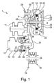
図1及び2に、本発明のそれぞれ異なる実施の形態に係るCVTパワートレーン1;41を簡略化して示してある。以下に、まず、それぞれ異なる実施の形態の共通点について説明する。それに続いて、かつその合間に、両実施の形態間の相違点について説明する。 FIGS. 1 and 2 show simplified CVT power trains 1; 41 according to different embodiments of the present invention. Hereinafter, common points of different embodiments will be described first. Subsequent and in the meantime, differences between the two embodiments will be described.
CVTパワートレーン1;41は、1次の駆動部3;43を備えている。1次の駆動部3;43は、例えば内燃機関(Brennkraftmaschine)である。内燃機関は、自動車で使用される場合、エンジン(Verbrennungsmotor)ともいう。
The CVT power train 1; 41 includes a
さらにCVTパワートレーン1;41は、2次の駆動部32;72を備えている。このCVTパワートレーン1;41と両駆動部3;43及び32;72とを装備している自動車は、ハイブリッド車両ともいう。ハイブリッド車両は、例えば商用車である。
Further, the CVT power train 1; 41 includes a
ハイブリッド車両の発進は、発進装置5;45により可能となる。発進装置5;45を介して、1次の駆動部3;43のトルクは、発進出力部分6;46に伝達される。発進出力部分6;46は、バリエータ10;50のバリエータ入力部に駆動接続されるか、または駆動接続可能である。
The hybrid vehicle can be started by the
バリエータ10;50は、駆動側の円錐円盤セット11;51及び被動側の円錐円盤セット12;52(プーリ)を有している。両円錐円盤セット11;51,12;52は、略示したにすぎない巻き掛け手段13;53により互いに連結されている。巻き掛け手段13;53は、例えば特殊チェーンである。
The
両円錐円盤セット11;51及び12;52を介して、1次の駆動部3;43と被動部15;55との間の変速比が無段階に調節可能である。被動部15;55は、少なくとも1つの駆動輪(図示せず)を有している。
Via both conical disk sets 11; 51 and 12; 52, the gear ratio between the
通常、被動部15;55は、少なくとも2つの駆動輪を有している。提供されたトルクを両駆動輪に分配するために、図1では、ディファレンシャル16が用いられる。ディファレンシャル16は、差動伝動機構ともいう。図1に示したディファレンシャル16は、円筒歯車18を有している。
Usually, the driven
ディファレンシャル16の円筒歯車18は、副伝動機構20の副伝動機構出力歯車19と係合している。副伝動機構20は、図1に看取可能であるように、被動側の円錐円盤セット12のバリエータ出力部に配設されている。
The
CVTパワートレーン1;41の1次の駆動部3;43には、トーショナルバイブレーションダンパ22;62が配設されている。トーショナルバイブレーションダンパ22;62は、1次の駆動部3;43と発進装置5;45との間に配置されている。発進装置5;45は、図1及び2では、発進クラッチ24;64として構成されている。発進クラッチ24;64は、湿式の多板クラッチである。
A
トーショナルバイブレーションダンパ22;62の入力部分25;65は、相対回動不能に1次の駆動部3;43のクランク軸に結合されている。トーショナルバイブレーションダンパ22;62の出力部分26;66は、一方では、発進クラッチ24;64の入力部をなしている。他方では、トーショナルバイブレーションダンパ22;62の出力部分26;66は、相対回動不能に伝動機構入力軸27;67に結合されている。つまり、伝動機構入力軸27;67は、トーショナルバイブレーションダンパ22;62の介在下で1次の駆動部3;43のクランク軸に駆動接続されている。
The
直接切り換え段(Direktschaltstufe)又は直結駆動段(Direktdurchtriebsstufe)30;70の切り換え装置29;69は、本発明に係るCVTパワートレーン1;41の第1の付加的なクラッチをなしている。矢印31;71は、直接切り換え段30;70がバリエータ10;50をバイパスするために用いられることを略示している。直接切り換え段30;70は、2次の駆動部32;72に接続されている。
The switching
図1に示したCVTパワートレーン1では、歯車28が結合部分33を介して、2次の駆動部32をなす電気機械36に接続されている。結合部分33と、歯車28と、直接切り換え段又は直結駆動段30とを介して、2次の駆動部32をなす電気機械36は、直接、すなわちバリエータ10を迂回して、トルク伝達のためにディファレンシャル16の円筒歯車18に接続可能である。
In the CVT power train 1 shown in FIG. 1, the
さらに結合部分33を介して、切り換え装置35のクラッチ入力部分34が、2次の駆動部32をなす電気機械36に接続されている。切り換え装置35は、第2の付加的なクラッチをなしている。第2の付加的なクラッチ35を介して、発進クラッチ24の発進出力部分6は、トルク伝達のために、2次の駆動部32をなす電気機械36に接続可能である。
Further, the
副伝動機構20は、プラネタリ伝動機構20と切り換え装置38とを有している。切り換え装置38は、第1の領域Lowと第2の領域Highとの間での切り換えを可能にする。切り換え装置38を介してバリエータ出力部に2つの運転領域が実現可能である。このとき、切り換え装置38は、第3の付加的なクラッチをなしている。
The
図1及び2に示したCVTパワートレーン1及び41の場合、2次の駆動部32;72をなす電気機械36;76は、主発進クラッチともいう発進クラッチ24;64に対して同心または同軸に配置されている。さらに、2次の駆動部32;72をなす電気機械36;76は、伝動機構入力軸27;67に対して同心または同軸に配置されている。
In the case of the
主発進クラッチ24;64は、電気機械36;76内に配置されている。電気機械36;76は、第1の付加的なクラッチ29;69と直結駆動段30;70とを介して駆動輪に、又は第2の付加的なクラッチ35;75を介してエンジン分岐、つまり1次の駆動部3;43に接続可能である。これにより、ハイブリッド車両の駆動輪に至るエンジン分岐及び電動モータ分岐の並列の、しかも互いに独立したパワーフローが可能である。
The main starting
付加的なクラッチ29,35;69,75は、好ましくは低コストの爪クラッチとして構成されている。付加的なクラッチ29,35;69,75により、電動モータまたは電気機械36;76は、同時に異なるモータ回転数で効率最適に駆動輪を駆動することができる。制動エネルギの回生時、制動エネルギは、バリエータ10;50の付加的な負荷なしに、直接切り換え段30;70を介して電動モータ36;76に導入可能である。同様に、電動モータ36;76により、付加的なトルクを、直接段30;70を介して駆動輪に、バリエータ10;50に付加的な負荷をかけることなく導入することができる(ブースト)。
The
主発進クラッチ24;64を第2の付加的なクラッチ35;75と1次の駆動部3;43のトーショナルバイブレーションダンパ22;62との間に配置したことにより、主発進クラッチ24;64は、例えば駆動輪の制動エネルギの回生時、1次の駆動部3;43の遮断クラッチ(Abtrennkupplung)として使用可能である。これにより付加的な切断クラッチ(Trennkupplung)は不要である。
By arranging the main starting
付加的なクラッチ35;75を電気機械36;76の半径方向内側に配置したことにより、特に構造スペースの面で有利な全体伝動機構配列が生じる。
The arrangement of the additional clutch 35; 75 radially inward of the
被動側の切断クラッチをなす第3の付加的なクラッチ38;78により、バリエータ10;50は、電動モータ分岐だけで直結駆動段30;70を介して走行すべきとき、簡単に被動側にて連結解除可能である。加えて、駆動側の付加的なクラッチ35;75と相俟って、バリエータ10;50は、完全に静止状態にもたらされ、これにより、特に低コストの走行を実現することができる。電気機械36;76が、車両の停止時、燃焼器分岐(Verbrennerzweig)を介してジェネレータとして運転されるべきときは、バリエータ10;50下流の被動側の切断クラッチ38;78が、構成次第では必要または有利でもある。
The third additional clutch 38; 78, which forms a driven-side disconnect clutch, allows the
後進ギヤ段をなすために用いられる回転方向逆転ユニットを省略することにより、コストを節減可能である。さらに伝動機構は、構造スペースの面でより有利、かつより軽量とすることができる。第3の付加的なクラッチをなす被動側の切断クラッチ38;78を介して、ハイブリッド車両のハイブリッドバッテリは、好ましくはハイブリッド車両の停止時に充電可能である。このことは、ハイブリッドバッテリが予期せず空となっていて、車両が電気的にしか後進走行できないときの非常時に必要である。 Costs can be saved by omitting the rotating direction reversing unit used for the reverse gear. Furthermore, the transmission mechanism can be more advantageous in terms of structural space and can be lighter. The hybrid battery of the hybrid vehicle is preferably rechargeable when the hybrid vehicle is stopped, via a driven disconnect clutch 38; 78 which forms a third additional clutch. This is necessary in an emergency when the hybrid battery is unexpectedly empty and the vehicle can only be driven backwards.
図2に示したCVTパワートレーン41は、例えば商用車、特に貨物自動車のパワートレーンである。被動側には、伝動機構出力軸56が配置されている。伝動機構出力軸56は、歯車段58を介してバリエータ出力部57に接続されている。歯車段58は、第3の付加的なクラッチ78を介してトルク伝達のために伝動機構出力軸56に接続可能である。
The
図2では、図1に示したCVTパワートレーン1とは異なり、副伝動機構60がバリエータ50の入力側に配置されている。さらに副伝動機構60は、プラネタリ伝動機構としてではなく、固定段の伝動機構(Feststufengetriebe)として構成されている。その他、副伝動機構60は、図1に示したCVTパワートレーン1の場合と同様に、2つの運転領域Low及びHighを実現するために用いられる。
2, unlike the CVT power train 1 shown in FIG. 1, a
直接切り換え段又は直結駆動段70は、図2では、矢印63により略示するように、歯車77と付加的な軸68とを介して、矢印71により略示するように、伝動機構出力軸56に接続されている。歯車77は、結合部分73を介して、2次の駆動部72をなす電気機械76に接続されている。その他、直結駆動段70は、図1に示したCVTパワートレーン1の場合と同様に機能する。
The direct switching stage or direct drive stage 70 is shown in FIG. 2 via a
さらに、結合部分73を介して、切り換え装置75のクラッチ入力部分74が、2次の駆動部72をなす電気機械76に接続されている。切り換え装置75は、第2の付加的なクラッチをなし、図1に示したCVTパワートレーン1における第2の付加的なクラッチ35と同様に機能する。
Further, the clutch input portion 74 of the
さらに図2には、例えば商用車の場合、補機駆動部をも歯車77を介して電気機械76に直接連結可能にする方法を示してある。補機駆動部は、PTOともいう。PTOなるアルファベットは、パワーテイクオフ(英Power‐Take‐off)の略である。図2に示した配列により、補機駆動部PTOは、ハイブリッド車両の停止時、電気機械76を介して、又は1次の駆動部43を介して、又は両分岐の協働を介して運転可能である。補機駆動部は、例えば液圧ポンプ又はコンプレッサであってもよい。
Further, FIG. 2 shows a method for enabling the auxiliary machine drive unit to be directly connected to the
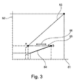
2領域CVTとしての構成時、直結駆動段30;70は、同時に両CVT走行領域Low及びHigh間の切り換え段として用いられるように設計可能である。さらに直結駆動段30;70は、電動モータとして働く電気機械36;76と相俟って、図3に看取可能であるように直接走行段としても用いられ得る。
When configured as a two-region CVT, the
図3は、図1及び2に示したCVTパワートレーン1;41に関する変速比特性マップを、デカルト座標系のグラフの形で示している。図3に示したデカルト座標系のグラフは、x軸81及びy軸82を有している。x軸81には、可変のバリエータ変速比を示してある。y軸82には、副伝動機構の伝動機構変速比を示してある。
FIG. 3 shows a gear ratio characteristic map for the CVT power train 1; 41 shown in FIGS. 1 and 2 in the form of a Cartesian coordinate system graph. The Cartesian coordinate system graph shown in FIG. 3 has an
特性線83は、ロー運転領域を示している。特性線84は、ハイ運転領域を示している。x軸81に対して平行に延びる一点鎖線85は、点Aにおけるロー領域83と点Bにおけるハイ領域84との間での切り換え可能性を略示している。点A及びB間の切り換えは、双方向矢印86により略示してある。
A
この場合、直結駆動段30;70の変速比は、好ましくは、2つのCVT運転領域又はCVT走行領域Low及びHighの好適な割り当てが生じるように選択される。さらに、変速比は、好ましくは、ハイブリッド車両が電気機械36;76だけで効率最適に走行可能であるように選択されている。
In this case, the gear ratio of the
全負荷下でのハイブリッド車両の発進時、電気機械36;76は、CVTバリエータ変速比の使用下で、直接ギヤ段なしに運転可能である。乗用車用伝動機構として使用した場合、切り換え段と、同時に電動モータ直接段との総パワートレーン変速比は、4〜7、好ましくは5〜6の範囲にある。
At the start of the hybrid vehicle under full load, the
直接段を用いた2領域CVTにおける運転領域間の切り換え動作時、電気機械36;76により、望ましくないドライブ力の中断も低減又は解消され得る。この電気的に支援される切り換え動作のために、機械的に燃焼器を介して支援される切り換え動作と比較して、有利には、それほど多くのクラッチ切り換えが必要とされない。これにより、切り換え動作をより迅速に実施可能でもある。
Undesirable drive force interruptions can also be reduced or eliminated by the
1 CVTパワートレーン
2
3 1次の駆動部
4
5 発進装置
6 発進出力部分
7
8
9
10 バリエータ
11 駆動側の円錐円盤セット
12 被動側の円錐円盤セット
13 巻き掛け手段
14
15 被動部
16 ディファレンシャル
17
18 円筒歯車
19 副伝動機構出力歯車
20 副伝動機構
21
22 トーショナルバイブレーションダンパ
23
24 発進クラッチ
25 入力部分
26 出力部分
27 伝動機構入力軸
28 歯車
29 切り換え装置
30 直接切り換え段
31 矢印
32 2次の駆動部
33 結合部分
34 クラッチ入力部分
35 切り換え装置
36 電気機械
37
38 切り換え装置
39
40
41 CVTパワートレーン
42
43 1次の駆動部
44
45 発進装置
46 発進出力部分
47
48
49
50 バリエータ
51 駆動側の円錐円盤セット
52 被動側の円錐円盤セット
53 巻き掛け手段
54
55 被動部
56 伝動機構出力軸
57 バリエータ出力部
58 歯車段
59
60 副伝動機構
61
62 トーショナルバイブレーションダンパ
63 矢印
64 発進クラッチ
65 入力部分
66 出力部分
67 伝動機構入力軸
68 付加的な軸
69 切り換え装置
70 直接切り換え段
71 矢印
72 2次の駆動部
73 結合部分
74 クラッチ入力部分
75 切り換え装置
76 電気機械
77 歯車
78 切り換え装置
79
80
81 x軸
82 y軸
83 特性線
84 特性線
85 一点鎖線
86 双方向矢印
1 CVT power train 2
3 Primary drive unit 4
5 Starting
8
9
DESCRIPTION OF
15 Driven
18
22 Torsional vibration damper 23
24
38 Switching device 39
40
41 CVT power train 42
43 Primary drive unit 44
45 Starting
48
49
50
55 Driven
60 Sub-transmission mechanism 61
62
80
81 x-axis 82 y-
Claims (10)
Applications Claiming Priority (3)
| Application Number | Priority Date | Filing Date | Title |
|---|---|---|---|
| DE102014201030.6 | 2014-01-21 | ||
| DE102014201030 | 2014-01-21 | ||
| PCT/DE2014/200715 WO2015110108A1 (en) | 2014-01-21 | 2014-12-15 | Cvt drivetrain and method for the operation thereof |
Publications (1)
| Publication Number | Publication Date |
|---|---|
| JP2017505258A true JP2017505258A (en) | 2017-02-16 |
Family
ID=52434470
Family Applications (1)
| Application Number | Title | Priority Date | Filing Date |
|---|---|---|---|
| JP2016547917A Pending JP2017505258A (en) | 2014-01-21 | 2014-12-15 | CVT power train and method of operating a CVT power train |
Country Status (5)
| Country | Link |
|---|---|
| US (1) | US10556498B2 (en) |
| JP (1) | JP2017505258A (en) |
| CN (1) | CN105916717B (en) |
| DE (1) | DE112014006223A5 (en) |
| WO (1) | WO2015110108A1 (en) |
Families Citing this family (13)
| Publication number | Priority date | Publication date | Assignee | Title |
|---|---|---|---|---|
| US10240667B2 (en) * | 2013-12-09 | 2019-03-26 | Schaeffler Technologies AG & Co. KG | CVT drive train |
| DE102016206278A1 (en) | 2016-04-14 | 2017-10-19 | Schaeffler Technologies AG & Co. KG | Powertrain for a hybrid motor vehicle |
| DE102016214816A1 (en) | 2016-08-10 | 2018-02-15 | Schaeffler Technologies AG & Co. KG | CVT powertrain |
| EP3322606B2 (en) * | 2016-10-06 | 2023-01-11 | Schaeffler Technologies AG & Co. KG | Hybrid module |
| DE102016222936A1 (en) | 2016-11-21 | 2018-05-24 | Schaeffler Technologies AG & Co. KG | CVT powertrain |
| DE102016222939A1 (en) | 2016-11-21 | 2018-05-24 | Schaeffler Technologies AG & Co. KG | CVT powertrain |
| CN109094352B (en) * | 2017-06-20 | 2023-10-20 | 舍弗勒技术股份两合公司 | Hybrid powertrain with CVT |
| CN107627832A (en) * | 2017-09-08 | 2018-01-26 | 重庆大学 | Reverse-flow type power coupling transmission system |
| DE102017121585A1 (en) | 2017-09-18 | 2019-03-21 | Schaeffler Technologies AG & Co. KG | coupling system |
| DE102017130494A1 (en) | 2017-12-19 | 2019-06-19 | Schaeffler Technologies AG & Co. KG | Hybrid powertrain |
| DE102018117323A1 (en) | 2018-07-18 | 2020-01-23 | Schaeffler Technologies AG & Co. KG | Drive unit with continuously variable transmission and drive train |
| DE102018131285A1 (en) | 2018-12-07 | 2020-06-10 | Schaeffler Technologies AG & Co. KG | CVT drivetrain for a hybrid vehicle |
| DE102019112165A1 (en) | 2019-05-09 | 2020-11-12 | Schaeffler Technologies AG & Co. KG | Method for controlling a hybrid drive train |
Citations (3)
| Publication number | Priority date | Publication date | Assignee | Title |
|---|---|---|---|---|
| JPH11107798A (en) * | 1997-10-08 | 1999-04-20 | Aisin Aw Co Ltd | Hybrid driving device |
| JP2000006690A (en) * | 1998-06-22 | 2000-01-11 | Toyota Motor Corp | Transmission control device for vehicle |
| JP2010261544A (en) * | 2009-05-11 | 2010-11-18 | Honda Motor Co Ltd | Power transmission device |
Family Cites Families (12)
| Publication number | Priority date | Publication date | Assignee | Title |
|---|---|---|---|---|
| CA2312752C (en) * | 1997-12-05 | 2003-07-08 | Toyota Jidosha Kabushiki Kaisha | Hybrid drive system |
| CN102518769B (en) * | 2005-07-23 | 2015-04-15 | 卢克摩擦片和离合器两合公司 | Power-splitting gearbox with several ratio ranges with steplessly adjustable ratios |
| JP4226610B2 (en) * | 2006-03-28 | 2009-02-18 | 本田技研工業株式会社 | Hybrid vehicle |
| DE102006049888A1 (en) | 2006-10-23 | 2008-04-24 | Robert Bosch Gmbh | Method for controlling combustion engine and electrical engine with hybrid propulsion of vehicle, involves arranging of clutch between electrical engine and drive train of vehicle |
| FR2907719B1 (en) | 2006-10-26 | 2009-06-12 | Inst Francais Du Petrole | MOVING DRIVE SYSTEM FOR A HYBRID VEHICLE AND METHOD USING SUCH A SYSTEM. |
| JP4263219B2 (en) * | 2007-03-30 | 2009-05-13 | 本田技研工業株式会社 | Power equipment |
| FR2922163B1 (en) | 2007-10-10 | 2010-02-26 | Inst Francais Du Petrole | MOVING DRIVE SYSTEM WITH MULTIPLE TRANSMISSION PATHS FOR A HYBRID VEHICLE AND METHOD FOR TRAINING IN DISPLACEMENT OF SAID VEHICLE |
| JP4913183B2 (en) * | 2009-07-15 | 2012-04-11 | ジヤトコ株式会社 | Continuously variable transmission for vehicle |
| DE102010012965A1 (en) | 2010-03-25 | 2011-09-29 | Voith Patent Gmbh | Powertrain for a motor vehicle |
| WO2011127892A1 (en) | 2010-04-12 | 2011-10-20 | Schaeffler Technologies Gmbh & Co. Kg | Cone pulley transmission |
| JP5581915B2 (en) * | 2010-09-06 | 2014-09-03 | 日産自動車株式会社 | Control device for hybrid vehicle |
| KR101683489B1 (en) * | 2014-09-25 | 2016-12-07 | 현대자동차 주식회사 | Power transmission apparatus for hybrid electric vehicle |
-
2014
- 2014-12-15 DE DE112014006223.5T patent/DE112014006223A5/en active Pending
- 2014-12-15 CN CN201480073632.9A patent/CN105916717B/en active Active
- 2014-12-15 WO PCT/DE2014/200715 patent/WO2015110108A1/en active Application Filing
- 2014-12-15 JP JP2016547917A patent/JP2017505258A/en active Pending
- 2014-12-15 US US15/112,961 patent/US10556498B2/en not_active Expired - Fee Related
Patent Citations (3)
| Publication number | Priority date | Publication date | Assignee | Title |
|---|---|---|---|---|
| JPH11107798A (en) * | 1997-10-08 | 1999-04-20 | Aisin Aw Co Ltd | Hybrid driving device |
| JP2000006690A (en) * | 1998-06-22 | 2000-01-11 | Toyota Motor Corp | Transmission control device for vehicle |
| JP2010261544A (en) * | 2009-05-11 | 2010-11-18 | Honda Motor Co Ltd | Power transmission device |
Also Published As
| Publication number | Publication date |
|---|---|
| DE112014006223A5 (en) | 2016-11-03 |
| WO2015110108A1 (en) | 2015-07-30 |
| US20160347165A1 (en) | 2016-12-01 |
| US10556498B2 (en) | 2020-02-11 |
| CN105916717A (en) | 2016-08-31 |
| CN105916717B (en) | 2019-08-20 |
Similar Documents
| Publication | Publication Date | Title |
|---|---|---|
| JP2017505258A (en) | CVT power train and method of operating a CVT power train | |
| US9527375B2 (en) | Powertrain with transmission-based motor/generator for engine starting and regenerative braking modes | |
| JP4331228B2 (en) | Power transmission device for vehicle | |
| CN104728373B (en) | power transmission device for vehicle | |
| JP6594312B2 (en) | CVT power train | |
| US8579748B2 (en) | In-vehicle power transmission device and power transmission system for vehicle | |
| JP5921773B2 (en) | Hybrid drive vehicle drive system | |
| JP7009622B2 (en) | Vehicles with hybrid-powertrain and hybrid-powertrain | |
| US20190168601A1 (en) | Transaxle device | |
| JP2013510027A (en) | Hybrid vehicle transmission | |
| KR20120005970A (en) | Drive system for a motor vehicle and motor vehicle having such a drive system | |
| JP2015527246A (en) | Vehicle drive train | |
| JP5736850B2 (en) | Drive device for hybrid vehicle | |
| JP2016540170A (en) | CVT transmission mechanism | |
| JP2008049819A (en) | Power transmission system | |
| KR101637281B1 (en) | Power transmission apparatus for hybrid electric vehicle | |
| KR101664750B1 (en) | Powertrain for hybrid vehicle | |
| CN111344181A (en) | Hybrid drive train | |
| KR101786338B1 (en) | Power train for hybrid vehicle | |
| JP4872697B2 (en) | Power transmission system | |
| JP2008044517A (en) | Power transmission system | |
| JP2012016988A (en) | Driving device for hybrid vehicle | |
| JP6494628B2 (en) | CVT transmission mechanism | |
| GB2543631A (en) | Torque transfer apparatus | |
| JP6512736B2 (en) | Hybrid powertrain |
Legal Events
| Date | Code | Title | Description |
|---|---|---|---|
| A621 | Written request for application examination |
Free format text: JAPANESE INTERMEDIATE CODE: A621 Effective date: 20171212 |
|
| A977 | Report on retrieval |
Free format text: JAPANESE INTERMEDIATE CODE: A971007 Effective date: 20190123 |
|
| A131 | Notification of reasons for refusal |
Free format text: JAPANESE INTERMEDIATE CODE: A131 Effective date: 20190204 |
|
| A02 | Decision of refusal |
Free format text: JAPANESE INTERMEDIATE CODE: A02 Effective date: 20190910 |