JP2017504737A - Wall elements - Google Patents
Wall elements Download PDFInfo
- Publication number
- JP2017504737A JP2017504737A JP2016538543A JP2016538543A JP2017504737A JP 2017504737 A JP2017504737 A JP 2017504737A JP 2016538543 A JP2016538543 A JP 2016538543A JP 2016538543 A JP2016538543 A JP 2016538543A JP 2017504737 A JP2017504737 A JP 2017504737A
- Authority
- JP
- Japan
- Prior art keywords
- felt
- layer
- corrugated
- layers
- wall element
- Prior art date
- Legal status (The legal status is an assumption and is not a legal conclusion. Google has not performed a legal analysis and makes no representation as to the accuracy of the status listed.)
- Pending
Links
- 230000002093 peripheral effect Effects 0.000 claims description 26
- 238000000034 method Methods 0.000 claims description 15
- 239000000853 adhesive Substances 0.000 claims description 9
- 230000001070 adhesive effect Effects 0.000 claims description 9
- 238000003466 welding Methods 0.000 claims description 6
- 238000003825 pressing Methods 0.000 claims description 5
- 238000005452 bending Methods 0.000 description 3
- 239000002131 composite material Substances 0.000 description 3
- 238000005520 cutting process Methods 0.000 description 3
- 238000004519 manufacturing process Methods 0.000 description 3
- 239000000463 material Substances 0.000 description 3
- 238000000465 moulding Methods 0.000 description 2
- 238000005192 partition Methods 0.000 description 2
- 230000000087 stabilizing effect Effects 0.000 description 2
- 239000000126 substance Substances 0.000 description 2
- 238000010521 absorption reaction Methods 0.000 description 1
- 230000005540 biological transmission Effects 0.000 description 1
- 230000015572 biosynthetic process Effects 0.000 description 1
- 238000004049 embossing Methods 0.000 description 1
- 238000010438 heat treatment Methods 0.000 description 1
- 238000005304 joining Methods 0.000 description 1
- 230000003287 optical effect Effects 0.000 description 1
- 230000006641 stabilisation Effects 0.000 description 1
- 238000011105 stabilization Methods 0.000 description 1
- 238000005728 strengthening Methods 0.000 description 1
- 230000003313 weakening effect Effects 0.000 description 1
Images


Classifications
-
- E—FIXED CONSTRUCTIONS
- E04—BUILDING
- E04B—GENERAL BUILDING CONSTRUCTIONS; WALLS, e.g. PARTITIONS; ROOFS; FLOORS; CEILINGS; INSULATION OR OTHER PROTECTION OF BUILDINGS
- E04B1/00—Constructions in general; Structures which are not restricted either to walls, e.g. partitions, or floors or ceilings or roofs
- E04B1/62—Insulation or other protection; Elements or use of specified material therefor
- E04B1/74—Heat, sound or noise insulation, absorption, or reflection; Other building methods affording favourable thermal or acoustical conditions, e.g. accumulating of heat within walls
- E04B1/82—Heat, sound or noise insulation, absorption, or reflection; Other building methods affording favourable thermal or acoustical conditions, e.g. accumulating of heat within walls specifically with respect to sound only
- E04B1/84—Sound-absorbing elements
- E04B1/8409—Sound-absorbing elements sheet-shaped
-
- E—FIXED CONSTRUCTIONS
- E04—BUILDING
- E04B—GENERAL BUILDING CONSTRUCTIONS; WALLS, e.g. PARTITIONS; ROOFS; FLOORS; CEILINGS; INSULATION OR OTHER PROTECTION OF BUILDINGS
- E04B1/00—Constructions in general; Structures which are not restricted either to walls, e.g. partitions, or floors or ceilings or roofs
- E04B1/62—Insulation or other protection; Elements or use of specified material therefor
- E04B1/74—Heat, sound or noise insulation, absorption, or reflection; Other building methods affording favourable thermal or acoustical conditions, e.g. accumulating of heat within walls
- E04B1/82—Heat, sound or noise insulation, absorption, or reflection; Other building methods affording favourable thermal or acoustical conditions, e.g. accumulating of heat within walls specifically with respect to sound only
- E04B1/84—Sound-absorbing elements
- E04B1/86—Sound-absorbing elements slab-shaped
-
- E—FIXED CONSTRUCTIONS
- E04—BUILDING
- E04B—GENERAL BUILDING CONSTRUCTIONS; WALLS, e.g. PARTITIONS; ROOFS; FLOORS; CEILINGS; INSULATION OR OTHER PROTECTION OF BUILDINGS
- E04B1/00—Constructions in general; Structures which are not restricted either to walls, e.g. partitions, or floors or ceilings or roofs
- E04B1/62—Insulation or other protection; Elements or use of specified material therefor
- E04B1/74—Heat, sound or noise insulation, absorption, or reflection; Other building methods affording favourable thermal or acoustical conditions, e.g. accumulating of heat within walls
- E04B1/82—Heat, sound or noise insulation, absorption, or reflection; Other building methods affording favourable thermal or acoustical conditions, e.g. accumulating of heat within walls specifically with respect to sound only
- E04B1/84—Sound-absorbing elements
- E04B2001/8414—Sound-absorbing elements with non-planar face, e.g. curved, egg-crate shaped
-
- E—FIXED CONSTRUCTIONS
- E04—BUILDING
- E04B—GENERAL BUILDING CONSTRUCTIONS; WALLS, e.g. PARTITIONS; ROOFS; FLOORS; CEILINGS; INSULATION OR OTHER PROTECTION OF BUILDINGS
- E04B1/00—Constructions in general; Structures which are not restricted either to walls, e.g. partitions, or floors or ceilings or roofs
- E04B1/62—Insulation or other protection; Elements or use of specified material therefor
- E04B1/74—Heat, sound or noise insulation, absorption, or reflection; Other building methods affording favourable thermal or acoustical conditions, e.g. accumulating of heat within walls
- E04B1/82—Heat, sound or noise insulation, absorption, or reflection; Other building methods affording favourable thermal or acoustical conditions, e.g. accumulating of heat within walls specifically with respect to sound only
- E04B1/84—Sound-absorbing elements
- E04B2001/8423—Tray or frame type panels or blocks, with or without acoustical filling
- E04B2001/8428—Tray or frame type panels or blocks, with or without acoustical filling containing specially shaped acoustical bodies, e.g. funnels, egg-crates, fanfolds
-
- E—FIXED CONSTRUCTIONS
- E04—BUILDING
- E04B—GENERAL BUILDING CONSTRUCTIONS; WALLS, e.g. PARTITIONS; ROOFS; FLOORS; CEILINGS; INSULATION OR OTHER PROTECTION OF BUILDINGS
- E04B1/00—Constructions in general; Structures which are not restricted either to walls, e.g. partitions, or floors or ceilings or roofs
- E04B1/62—Insulation or other protection; Elements or use of specified material therefor
- E04B1/74—Heat, sound or noise insulation, absorption, or reflection; Other building methods affording favourable thermal or acoustical conditions, e.g. accumulating of heat within walls
- E04B1/82—Heat, sound or noise insulation, absorption, or reflection; Other building methods affording favourable thermal or acoustical conditions, e.g. accumulating of heat within walls specifically with respect to sound only
- E04B1/84—Sound-absorbing elements
- E04B2001/8457—Solid slabs or blocks
- E04B2001/8461—Solid slabs or blocks layered
- E04B2001/8471—Solid slabs or blocks layered with non-planar interior transition surfaces between layers, e.g. faceted, corrugated
Landscapes
- Physics & Mathematics (AREA)
- Engineering & Computer Science (AREA)
- Architecture (AREA)
- Acoustics & Sound (AREA)
- Electromagnetism (AREA)
- Civil Engineering (AREA)
- Structural Engineering (AREA)
- Laminated Bodies (AREA)
- Finishing Walls (AREA)
- Floor Finish (AREA)
- Panels For Use In Building Construction (AREA)
Abstract
本発明はフェルトパネル(2)を備えた壁要素(1)に関し、フェルトパネル(2)は少なくとも2つのフェルト層を備え、少なくとも1つのフェルト層が少なくとも1つの上面に三次元構造を有している。この構成において、フェルトパネル(2)は上層(OS)として平面フェルト層(11)を備え、フェルトパネル(2)は下層(US)として平面フェルト層(12)を備え、フェルトパネル(2)は中層(MS)として少なくとも1つの波形フェルト層(21)を備え、上層(OS)に隣接する波形フェルト層(21)は、その上面(21a)において、波形の頂部(21b)によって形成されている上側頂点線(21c)又は頂点の領域にて上層(OS)に接続されており、下層(US)に隣接する波形フェルト層(22)は、その下面(22d)において、波形の谷部(22e)によって形成されている下側頂点線(22f)又は頂点の領域にて下層(US)に接続されている。The present invention relates to a wall element (1) comprising a felt panel (2), the felt panel (2) comprising at least two felt layers, the at least one felt layer having a three-dimensional structure on at least one upper surface. Yes. In this configuration, the felt panel (2) includes a planar felt layer (11) as an upper layer (OS), the felt panel (2) includes a planar felt layer (12) as a lower layer (US), and the felt panel (2) At least one corrugated felt layer (21) is provided as an intermediate layer (MS), and the corrugated felt layer (21) adjacent to the upper layer (OS) is formed on its upper surface (21a) by a corrugated top (21b). The corrugated felt layer (22) that is connected to the upper layer (OS) at the upper vertex line (21c) or the apex region and is adjacent to the lower layer (US) has a corrugated trough (22e) on its lower surface (22d). ) Are connected to the lower layer (US) at the lower vertex line (22f) or the vertex region.
Description
本発明は請求項1の前提部分に記載の壁要素に関する。
特開平10−72883号から、フェルトパネルを備え、フェルトパネルが少なくとも2つのフェルト層を有し、少なくとも1つのフェルト層が少なくとも1つの上面に三次元構造を有している壁要素が公知である。このような壁要素の製造は、切断工程のせいで技術的に難しい。
The invention relates to a wall element according to the preamble of claim 1.
JP-A-10-72883 discloses a wall element comprising a felt panel, the felt panel having at least two felt layers, and at least one felt layer having a three-dimensional structure on at least one upper surface. . The manufacture of such wall elements is technically difficult due to the cutting process.
本発明が解決しようとする課題は、特に1つの嵩高領域において全面での接合をしないようにした状態で製造されている、少なくとも3層の純フェルトパネルを備えた壁要素を提供することである。さらに、本発明は、フェルト層の製造工程を容易にするという課題を解決しようとしている。最後に、本発明は、最も多様な要件を満たすために、追加のフェルト層によって、壁要素の厚さを容易に適合させるという課題を解決しようとしている。 The problem to be solved by the present invention is to provide a wall element comprising at least three layers of pure felt panels, which is manufactured in a state where the entire surface is not joined, particularly in one bulky region. . Furthermore, this invention is going to solve the subject of making the manufacturing process of a felt layer easy. Finally, the present invention seeks to solve the problem of easily adapting the thickness of the wall element with an additional felt layer to meet the most diverse requirements.
上記課題は、請求項1の特徴を示す、請求項1の前提部分の特徴に基づいて解決される。各下位請求項は、効果的かつ好適な、さらなる変形例を提供している。
本発明においてクレームされる、フェルトパネルを備えた壁要素において、フェルトパネルは、その上層として平面フェルト層を、その下層として平面フェルト層を、その中層として少なくとも1つの波形フェルト層を備え、上層に隣接する波形フェルト層は、その上面上において、波形の頂部によって形成されている上側頂点線又は頂点の領域にて上層に接続されており、下層に隣接する波形フェルト層は、その下面上において、波形の谷部によって形成されている下側頂点線又は頂点の領域にて下層に接続されている。このようにして、純物質の少なくとも3層構造の複合体が製造されており、この複合体では、個々のフェルト層の間において全面で接続されることが回避されている。波形フェルト層を上面と下面とに接して使用するおかげで、3層構造及び多層構造のフェルトパネルの場合に、材料を増大させることを回避することができる。平面フェルト層と両側を波形にした少なくとも1つのフェルト層とからフェルトパネルを構成することによって、製造方法は、切断する工程と、切断片の一部分を成形する工程と、全ての切断片を接合する工程のみを含むこととなる。特に、加工の安全性の面で重大な単一のフェルト層の分割が、本発明に記載の複合体では必要とされない。
The object is solved on the basis of the features of the premise of claim 1, which shows the features of claim 1. Each sub-claim provides further variations that are effective and suitable.
In a wall element comprising a felt panel as claimed in the present invention, the felt panel comprises a planar felt layer as its upper layer, a planar felt layer as its lower layer, and at least one corrugated felt layer as its middle layer. The adjacent corrugated felt layer is connected to the upper layer on its upper surface at the upper vertex line or the region of the apex formed by the top of the corrugation, and the corrugated felt layer adjacent to the lower layer is on its lower surface, The lower apex line or apex region formed by the corrugated valley is connected to the lower layer. In this way, a composite of at least a three-layer structure of a pure substance is produced, and in this composite, it is avoided that the entire felt is connected between the individual felt layers. Thanks to the use of the corrugated felt layer in contact with the upper and lower surfaces, it is possible to avoid increasing the material in the case of three-layer and multilayer felt panels. By constructing a felt panel from a flat felt layer and at least one felt layer corrugated on both sides, the manufacturing method joins all the cut pieces, the step of cutting, the step of forming a part of the cut piece Only the process will be included. In particular, the division of a single felt layer, which is critical in terms of processing safety, is not required in the composite according to the invention.
さらに、接触している2つ以上の波形フェルト層を備えたフェルトパネルにおいて、互いに接触している波形フェルト層同士を、それぞれの頂点線が平行な面内で延びており、かつ、互いに対して少なくとも20°、特に90°の角度をなすような方向に向けてもよい。このようにして、フェルトパネルは多方向の向きに対する曲げ剛性を有する。 Furthermore, in a felt panel having two or more corrugated felt layers that are in contact, the corrugated felt layers that are in contact with each other extend in a plane whose respective vertex lines are parallel to each other, and It may be oriented in a direction that makes an angle of at least 20 °, in particular 90 °. In this way, the felt panel has bending stiffness with respect to multidirectional orientations.
また、フェルトパネルにおいて、中層として少なくとも2つの波形フェルト層と、各波形フェルト層同士の間に中間層として平面フェルト層とを有していてもよく、各波形フェルト層は、波形の頂部によって形成されている上側頂点線又は頂点の領域において、かつ/あるいは、波形の頂部によって形成されている下側頂点線又は頂点の領域において、それぞれが隣接する中間層又は複数の中間層に接続される。フェルトパネルをこのように構成することで、フェルトパネルの全てのフェルト層が、線状あるいは点状の複数の接続部によって、互いに確実に接合される。 Further, the felt panel may have at least two corrugated felt layers as intermediate layers and a planar felt layer as an intermediate layer between the corrugated felt layers, and each corrugated felt layer is formed by the top of the corrugated layer. Are connected to an adjacent intermediate layer or a plurality of intermediate layers, respectively, in the upper vertex line or vertex region being applied and / or in the lower vertex line or vertex region formed by the top of the corrugation. By configuring the felt panel in this way, all the felt layers of the felt panel are securely joined to each other by a plurality of linear or dotted connection portions.
また、中間層として平面フェルト層を備えたフェルトパネルの場合、同じ平面フェルト層に接続されている波形フェルト層は、互いの位置関係が、それぞれの頂点線が平行な面内で延びており、かつ、互いに対して少なくとも20°、特に90°の角度をなすような方向に向けられていてもよい。このようにして、フェルトパネルに、複数の方向における曲げ剛性が与えられている。 Further, in the case of a felt panel having a plane felt layer as an intermediate layer, corrugated felt layers connected to the same plane felt layer extend in a plane in which each vertex line is parallel to each other, And they may be oriented in a direction that makes an angle of at least 20 °, in particular 90 ° with respect to each other. In this way, the felt panel is given bending rigidity in a plurality of directions.
フェルトパネルは、10mmから50mmの間、好ましくは20mmから40mmの間、特に30mm前後の厚さを有するように構成されてもよい。このような寸法のフェルトパネルは、ピンボードや間仕切り壁としての使用に適している。 The felt panel may be configured to have a thickness between 10 mm and 50 mm, preferably between 20 mm and 40 mm, in particular around 30 mm. The felt panel having such dimensions is suitable for use as a pin board or a partition wall.
波形フェルト層のために、4mmから20mmの間、好ましくは6mmから15mmの間、特に8mm前後の厚さの平面フェルト層が使用されてもよく、波形フェルト層はプレス加工により製造されている。このようなフェルト層は固有の安定性が良く、これにより、このようなフェルト層は取り扱う過程で不要なねじれを生じてしまうこともなく容易に取り扱えるため、加工が容易になる。 For the corrugated felt layer, a planar felt layer with a thickness of between 4 mm and 20 mm, preferably between 6 mm and 15 mm, in particular around 8 mm may be used, the corrugated felt layer being produced by pressing. Such a felt layer has good intrinsic stability, which makes it easy to handle such a felt layer without causing unnecessary twisting in the process of handling.
波形フェルト層又は複数のフェルト層の波形の頂部同士の間、及び、波形フェルト層又は複数のフェルト層の波形の谷部同士の間に、空洞が形成されてもよい。このようにして、フェルトパネルの曲げやねじれに対する剛性が増し、また、これにより、フェルトパネルの防音性と断熱性の両方が向上する。 Cavities may be formed between the corrugated tops of the corrugated felt layer or the plurality of felt layers and between the corrugated valleys of the corrugated felt layer or the plurality of felt layers. In this way, the rigidity of the felt panel against bending and twisting is increased, and this improves both the soundproofing and heat insulating properties of the felt panel.
さらに、少なくとも1つの島状領域を有するようにフェルトパネルを構成してもよく、この島状領域内では、平面フェルト層と少なくとも1つの波形フェルト層が、全面において平らな状態で互いに重なって広がっており、特に全面で接合されている。1つ以上の島状領域を形成しているため、フェルトパネルの力学的性質をさらに高めることができ、特に、辺長がメートル規模の大きなフェルトパネルに対して、十分な固有の安定性を与えることもできる。 Further, the felt panel may be configured to have at least one island-like region, and in this island-like region, the planar felt layer and the at least one corrugated felt layer spread over each other in a flat state over the entire surface. In particular, they are joined on the entire surface. The formation of one or more island-like regions can further enhance the mechanical properties of the felt panel, and provide sufficient inherent stability, especially for felt panels with large side lengths You can also
島状領域は、全周囲にわたって閉鎖されている周縁領域として構成していてもよい。このようにして、空洞はフェルトパネルの外縁に対して閉鎖されており、これにより損傷及び/又は汚損から保護されている。さらに、フェルトパネルは、島状領域によって作成された環状部によって強化されている。 The island-shaped region may be configured as a peripheral region that is closed over the entire periphery. In this way, the cavity is closed against the outer edge of the felt panel, thereby protecting it from damage and / or fouling. Furthermore, the felt panel is reinforced by an annulus created by the island regions.
フェルトパネルは、少なくとも1つの島状領域に隣接する嵩高領域の厚さが、少なくとも1つの島状領域内のフェルトパネルの厚さよりも厚く、これらの厚さは各々、平面フェルト層のうちの1つの広がりに直交して測定されている。島状領域の厚さの方が薄いため、島状領域は特に加工しやすい。 The felt panel has a bulky region adjacent to the at least one island region that is thicker than a felt panel in the at least one island region, each of which is one of the planar felt layers. Measured perpendicular to two spreads. Since the island-like region is thinner, the island-like region is particularly easy to process.
また、島状領域を、フェルトパネルの周りに、その外縁において一区画にのみ広がる周縁領域として構成してもよく、あるいは、複数の島状領域を、フェルトパネルの周りに、その外縁において数個の区画として互いに間隔をあけて配置されている複数の周縁領域として構成してもよい。このようにして、フェルトパネルは強化され、また同時に、空洞内の水分の吸い取りや空洞外への排出がさらに維持されるように、開放された空洞も保持している。 Alternatively, the island region may be configured as a peripheral region that extends around the felt panel and only in one section at the outer edge, or several island regions are formed around the felt panel at the outer edge. You may comprise as several peripheral area | regions arrange | positioned as a division of this at intervals. In this way, the felt panel is strengthened and at the same time holds open cavities so that the absorption of moisture in the cavities and the discharge out of the cavities is further maintained.
壁要素は、フェルトパネルに加えて支持部を備えていてもよい。フェルトパネルと相互に作用する支持部のおかげで、フェルトパネルをずれないようにしっかり固定して位置決めし、パネルをさらに強化することができる。 The wall element may include a support in addition to the felt panel. Thanks to the support that interacts with the felt panel, the felt panel can be firmly fixed and positioned so as not to slip, further strengthening the panel.
基部と少なくとも1つのロッドとを有するように支持部を構成してもよく、ロッドはフェルトパネルの空洞のうちの1つに適合しており、フェルトパネルが支持部によって担持されるようにロッドを空洞に挿入可能である。このようにして、ロッド及び支持部の容易な接続が確実になされる。 The support may be configured to have a base and at least one rod, the rod is adapted to one of the cavities of the felt panel and the rod is arranged so that the felt panel is carried by the support. It can be inserted into the cavity. In this way, easy connection between the rod and the support is ensured.
さらに、支持部には少なくとも1つのロッドを設けることができ、ロッドは、両側の端部においてフェルトパネルから突出するように、空洞のうちの1つを通って延びる。
個々のフェルト層同士を接続するために、フェルト層同士は、接着剤を使用する接合加工によって、特に接着剤を使用する接着加工によって、及び/又は、接着剤を使用しない接合加工、特に溶接加工、好ましくは超音波溶接又は振動溶接によって、接続されてもよい。このような方法を、簡素な技術手段で実施することができる。
Furthermore, the support can be provided with at least one rod, which extends through one of the cavities so as to protrude from the felt panel at both ends.
In order to connect the individual felt layers, the felt layers can be joined together by a bonding process using an adhesive, in particular by an adhesive process using an adhesive and / or a bonding process, in particular a welding process without using an adhesive. , Preferably connected by ultrasonic welding or vibration welding. Such a method can be implemented with simple technical means.
本発明の概念において、波形フェルト層とは、弧状の波形フェルト層及びジグザグ状の波形フェルト層の両方、ならびに、具体的には成形工程で製造される、特にエンボス型を使用して、特に加熱作用下で製造される、断面が台形状の波形フェルト層を意味するものと解釈される。本発明の観念において、断面が台形状の波形フェルト層に関して、上側頂点線及び下側頂点線とは、上側頂上面及び下側頂上面を意味する。 In the concept of the present invention, a corrugated felt layer means both an arcuate corrugated felt layer and a zigzag corrugated felt layer, and in particular heating using an embossing mold, in particular produced in a molding process. It is taken to mean a corrugated felt layer produced under action with a trapezoidal cross section. In the concept of the present invention, with respect to the corrugated felt layer having a trapezoidal cross section, the upper vertex line and the lower vertex line mean the upper top surface and the lower top surface.
本発明のさらなる詳細は、模式的に表示された例示の実施形態により各図面中に説明される。 Further details of the invention are illustrated in the figures by means of exemplary embodiments schematically represented.
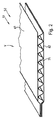
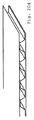
図1は、第1フェルトパネル2を備えた第1壁要素1の部分斜視図を示したものであり、ここでフェルトパネル2とは、1つの波形フェルト層21と2つの平面フェルト層11,12とを示している。第1平面フェルト層11は上層OSを、第2平面フェルト層12は下層USを、波形フェルト層21は中層MSをそれぞれ構成している。上層OSに隣接する波形フェルト層21は、上面21a上において、波形の頂部21bが形成する上側頂点線21cの領域にて上層OSに接続されている。下層USに隣接する波形フェルト層21は、下面21d上において、波形の谷部21eが形成する下側頂点線21fの領域にて下層USに接続されている。ここでは、フェルト層11,12とフェルト層21との接続は、図示していない接着剤で行われている。波形フェルト層21は、ジグザグ状の波形フェルト層21として構成されており、平面フェルト層から、2つの金型の間でのプレス成形にて形成されている。周縁領域Rによって形成された島状領域IBでは、波形フェルト層21は、平面フェルト層11,12の間で平らにプレスされ、全面で両層に接着されている。変形していない嵩高領域Vでは、波形の頂部21bと上側フェルト層11との間、及び波形の谷部21eと下側フェルト層12との間に、フェルト層21の三次元構成によって、互いに平行に延びている空洞Hがいかにそれぞれ形成されているかに気が付くことができるであろう。嵩高領域Vにおいて、フェルトパネル2は厚さDVを有し、この厚さDVは、フェルトパネル2が周縁領域Rにおいて有する厚さDRよりも厚い。フェルトパネル2に用いられているフェルト材料とともに、これらの空洞Hによって、壁要素1は、防音材としての特に優れた特性が得られる。さらに、フェルトパネル2を純物質で構成することによって、フェルトパネル2のリサイクルがしやすくなる。
FIG. 1 shows a partial perspective view of a first wall element 1 with a
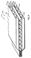
図2は、第2フェルトパネル52を備えた第2壁要素51の部分斜視図を示したものであり、ここでフェルトパネル52とは、1つの波形フェルト層71と2つの平面フェルト層61,62とを嵩高領域Vに示している。壁要素51は、図1に示されている壁要素と同様に設計されている。図1とは、波形フェルト層71が、ジグザグ状の波形フェルト層ではなく、波状の波形フェルト層として構成されている点のみが異なっている。
FIG. 2 shows a partial perspective view of a
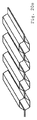
図3は、第3フェルトパネル102を備えた第3壁要素101の部分斜視図を示したものであり、ここでフェルトパネル102は、2つの波形フェルト層121,122と2つの平面フェルト層111,122とを備えている。第3フェルトパネル102の基本的な構成に関しては、図1の説明を参照されたい。平面フェルト層111は上層OSを構成し、平面フェルト層112は下層USを構成している。波形フェルト層121,122は中層MSを構成している。ここで、フェルト層111とフェルト層121,及びフェルト層112とフェルト層122はそれぞれ、図1で説明したように、壁要素101の嵩高領域V内で接合されている。2つの波形フェルト層121,122の頂点線121f,122cは互いに対して90°の角度で延びているため、上側波形フェルト層121は、その下側頂点線121fによって、下側波形フェルト層122の上側頂点線122cに点状に接合されている。壁要素101及びフェルトパネル102の周縁領域Rとして構成されている島状領域IB1は4層構造であり、4つのフェルト層は全て平らにプレスされて、接着されている。
FIG. 3 shows a partial perspective view of a
図4は、第4フェルトパネル152を備えた第4壁要素151の部分斜視図を示したものであり、フェルトパネル152は、2つの波形フェルト層171,172と2つの平面フェルト層161,162とを備えている。壁要素151は、図3に示されている壁要素と同様に設計されている。図3とは、波形フェルト層171,172が、ジグザグ状の波形フェルト層ではなく、波状の波形フェルト層として構成されている点のみが異なる。
FIG. 4 shows a partial perspective view of a
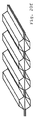
図5は、第5フェルトパネル202を備えた第5壁要素201の部分斜視図を示したものであり、フェルトパネル202は、3つの波形フェルト層221,222,223と4つの平面フェルト層211,212,213,214とを備えている。第1平面フェルト層211は上層OSを構成し、第2平面フェルト層212は下層USを構成している。第3平面フェルト層213と第4平面フェルト層214はそれぞれ中間層ZSを構成している。中間層ZSは波形フェルト層221,222,223の間にあり、これらとともに中層MSを構成している。第5フェルトパネル202の基本的な構成に関しては、図1の説明を参照されたい。フェルト層211とフェルト層221,及びフェルト層212とフェルト層222はそれぞれ、図1で説明したように、壁要素201の嵩高領域V内で接合されている。嵩高領域Vにおいて、上側波形フェルト層221は、その下側頂点線221fによって、上側中間層ZSつまり213に接合されており、下側波形フェルト層221は、その上側頂点線222eによって、下側中間層ZSつまり214に接合されている。真ん中の波形フェルト層223は、上側頂点線223eによって上側中間層ZSつまり213に接合され、かつ、下側頂点線223fによって下側中間層ZSつまり214に接合されている。壁要素201又はフェルトパネル202の周縁領域Rとして形成されている島状領域は7層構造であり、7つのフェルト層は全て平らにプレスされて、接着されている。上側波形フェルト層221と下側波形フェルト層222のそれぞれの空洞Hは互いに平行に延びている。真ん中の波形フェルト層223の空洞Hは、上側波形フェルト層221と下側波形フェルト層222のそれぞれの空洞Hを横切るように延びている。
FIG. 5 shows a partial perspective view of a
図6は、第6フェルトパネル252を備えた第6壁要素251の部分斜視図を示したものであり、フェルトパネル252は、3つの波形フェルト層271,272,273と4つの平面フェルト層261,262,263,264とを備えている。壁要素251は、図5に示されている壁要素と同様に設計されている。図5とは、波形フェルト層271,272,273が、ジグザグ状の波形フェルト層ではなく、波状の波形フェルト層として構成されている点のみが異なる。
FIG. 6 shows a partial perspective view of a
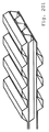
図7は、第7フェルトパネル302を備えた第7壁要素301の部分斜視図を示したものであり、フェルトパネル302は、5つの波形フェルト層321〜325と6つの平面フェルト層311〜316を備えている。その構成に関しては、図5の説明を参照されたい。なぜなら、図7に示されている例示の実施形態においては、付加的な波形層324,325と付加的な平面層315,316によって中層MSが拡張されたものであるが、中層MSにおいて波形フェルト層と平面フェルト層が交互に配列されている基本構成は保たれているからである。
FIG. 7 shows a partial perspective view of a
図8は、第8フェルトパネル352を備えた第8壁要素351の部分斜視図を示したものであり、フェルトパネル352は、5つの波形フェルト層371〜375と6つの平面フェルト層361〜366とを備えている。壁要素351は、図7に示されている壁要素と同様に設計されている。図7とは、波形フェルト層371〜375が、ジグザグ状の波形フェルト層ではなく、波状の波形フェルト層として構成されている点のみが異なる。
FIG. 8 shows a partial perspective view of an
図9は、フェルトパネル402を備えた第9壁要素401の図を示したものである。ここで、本図は、平面フェルト層411から形成されているフェルトパネル402の上層OSの平面図である。この平面図において、嵩高領域Vと、嵩高領域Vを完全に取り囲み、周縁領域Rとして構成されている島状領域IB1とをはっきりと認識できるであろう。フェルトパネル402はここでは、嵩高領域Vと島状領域IB1の両方において、形状が正方形である。
FIG. 9 shows a view of a
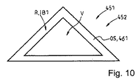
図10は、フェルトパネル452を備えた第10壁要素451の図を示したものである。ここで、本図は、平面フェルト層451から形成されているフェルトパネル452の上層OSの平面図である。この平面図において、嵩高領域Vと、嵩高領域Vを完全に取り囲み、島状領域IB1として構成されている周縁領域Rとをはっきりと認識できるであろう。フェルトパネル452はここでは、嵩高領域Vと島状領域IB1の両方において、形状が三角形である。
FIG. 10 shows a view of a tenth wall element 451 with a felt
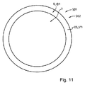
図11は、フェルトパネル502を備えた第11壁要素501の図を示したものである。ここで、本図は、平面フェルト層511から形成されているフェルトパネル502の上層OSの平面図である。この平面図において、嵩高領域Vと、嵩高領域Vを完全に取り囲み、島状領域IB1として構成されている周縁領域Rとをはっきりと認識できるであろう。フェルトパネル502はここでは、嵩高領域Vと島状領域IB1の両方において、形状が円形である。
FIG. 11 shows a view of an
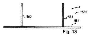
図12は、第12壁要素551の第12フェルトパネル552を示したものであり、第12フェルトパネル552は形状が正方形であり、3辺を囲む周縁領域Raとして構成された島状領域IB1を備えているため、嵩高領域Vは一辺S552において、フェルトパネル552の1つの外縁Uに対して開放された状態で構成されている。よって、フェルトパネル552の空洞Hはこの辺では開放されている。
FIG. 12 shows a
図13は、第12壁要素551の支持部Tを側面図で示したものである。支持部Tは、図12に示されているフェルトパネル552の組み立てに供されるものである。支持部Tは、台581と、台581に接合されている2つのロッド582,583からなる。
FIG. 13 shows the support portion T of the
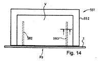
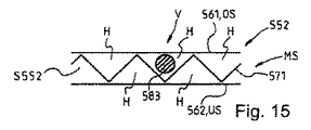
図14は、第12壁要素551を組み立てた形態で示したものである。組み立て工程において、支持部Tは自身のロッド582,583で、辺S552においてフェルトパネル552内に、中層MS内のフェルトパネル552の嵩高領域V内に形成されている空洞H内へとロッド582,583が導かれるように(図15参照)押し込まれている。フェルトパネル552の嵩高領域V内でのロッド583の配置は、図15に示されている断面図で見ることができる。中層MSは、2つの平面フェルト層561,562の間にある波形フェルト層571によって形成されており、平面フェルト層561,562は、上層OSと下層USをそれぞれ構成している。
FIG. 14 shows the
図16は第13壁要素601を示したものである。壁要素601は、フェルトパネル602と、2つのロッド631,632から形成される支持部Tとを備えている。フェルトパネル602は、嵩高領域Vと、周縁領域Ra,Rbとして構成された、対向する2つの島状領域IB1,IB2とを有している。島状領域IB1,IB2の間で、嵩高領域Vは、フェルトパネル602のうちの2辺S602a,S602bにある外縁Uにおいて開放されている。嵩高領域Vにおいて、上側のロッド631は、フェルトパネル602の中層MS内に形成されている空洞Hを貫通している。嵩高領域Vにおいて、下側のロッド632も同様に、フェルトパネル602の中層MS内に形成されている空洞Hを通って延びている。フェルトパネル602から突出しているロッド631,632の端部631a,631b又は端部632a,632bにおいて、壁要素601の掛着や固定が簡単に行える。
FIG. 16 shows the
図17は、構成が図3に示されている第3壁要素に相当する第14壁要素651の部分斜視図を示したものであり、壁要素651のフェルトパネル652は3つの島状領域IB1,IB2,IB3を備えている。ここでは、第1島状領域IB1は周縁領域Rとして構成されており、第2島状領域IB2と第3島状領域IB3はそれぞれ中間の島状部として、フェルトパネル652の嵩高領域V内に配置され、2つの島状領域IB2,IB3は、第1波形フェルト層671と第2波形フェルト層672の間にある鏡映面SEに関して鏡映対称で配置されている。ここで2つの島状領域IB2,IB3はそれぞれ、両側ポケットTA2a,TA2b,及び両側ポケットTA3a,TA3bとして構成されており、両側ポケットTA2a,TA2b,及び両側ポケットTA3a,TA3bは、上層OS及び下層USを構成する、外側にある平面フェルト層661,662から形成されており、波形層671,672を平らにプレスして形成されている。ここで4つのフェルト層661,662,671,672は、島状領域IB2,IB3内で平らにプレスされて接合されている。
FIG. 17 shows a partial perspective view of a
図18は、構成が図3に示されている第3壁要素に相当し、フェルトパネル702を備えた第15壁要素701の部分斜視図を示したものである。図17に示されている壁要素と同様に、図18に示されている壁要素701もまた3つの島状領域IB1,IB2,IB3を有している。図17に示されているフェルトパネルとは異なり、これらの領域は、波形フェルト層721と波形フェルト層722の間にある鏡映面SEに関して非対称で配置されている。ここで、中間の島状部として構成され、フェルトパネル702の嵩高領域Vにより囲まれている2つの島状領域IB2,IB3は、上層OSを構成する平面フェルト層711が、下層USを構成する平面フェルト層712に向かって下方向にプレスされているように構成されている。2つの島状領域IB2,IB3は、下層USは変形しないままであり、波形層721,722が下層US上に平らにプレスされており、上層OSは変形して、それぞれの島状領域IB2,IB3内で上側波形層721上に平らに広がるようにかなり深く引き込まれているように構成されており、4つの層711,712,721,722は全てともに接合されている。第2島状領域IB2と第3島状領域IB3はそれぞれ、片側ポケットTA2c,TA3cとして構成されている。
FIG. 18 shows a partial perspective view of a
図19は、構成が図1に示されている第1壁要素に相当する第16壁要素751の部分斜視図を示したものであり、フェルトパネル752は形状がアーチ形である。ここでフェルトパネル752は、波形フェルト層771の上側頂点線771c又は下側頂点線771fに平行な軸aを中心としたアーチ形である。フェルトパネル752が軸aを中心に湾曲した状態である場合に、上層OSつまり761と波形フェルト層771との間、及び波形フェルト層771と下層USつまり762との間のみで接続されることが好ましい。
FIG. 19 shows a partial perspective view of a
フェルトパネルの少なくとも1つの島状領域内に、及び/又は、少なくとも1つの嵩高領域内に、少なくとも1つの開口又は1つの穿孔を有するようにしてもよく、この場合、フェルトパネルにより形成された壁要素は、例えば少なくとも1つの掛け具、例えばねじ、釘、又は鉤によって固定することができる。 There may be at least one opening or one perforation in at least one island region of the felt panel and / or in at least one bulky region, in which case the wall formed by the felt panel The element can be secured, for example, by at least one hanger, such as a screw, nail, or scissors.
上述の壁要素は、特にピンボードとして、及び/又は、間仕切りとして、使用することが意図されている。
図20a〜20lは、壁要素又はこれらの壁要素の個々の層の別の変形実施形態を模式的に示したものである。
The wall elements described above are intended to be used in particular as pinboards and / or as partitions.
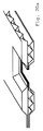
FIGS. 20a-20l schematically show another variant embodiment of the wall elements or the individual layers of these wall elements.
図20aは、全てのフェルト層が次々と平らに重なり、接合されている領域内において、押圧された箇所を有する壁要素を示している。このように、壁要素は、個々のフェルト層の集合体によって強化されている。必要に応じて、押圧された箇所にノッチの形態で開口が設けられ、これにより、壁要素をこのようにして脆弱化することなく、壁要素の光透過性が実現される。 FIG. 20a shows a wall element that has a pressed point in the region where all the felt layers overlap one after the other and are joined. In this way, the wall element is reinforced by an assembly of individual felt layers. If necessary, an opening in the form of a notch is provided in the pressed location, whereby the light transmission of the wall element is realized without weakening the wall element in this way.
図20bは、断面が台形状の波形フェルト層として形成されており、かつ、頂点線が頂上面によって形成されている、波形フェルト層を単独で示したものである。このような断面が台形状の波形フェルト層は、図20c〜20lに示されている他の壁要素において使用される。 FIG. 20b shows the corrugated felt layer alone, the cross section being formed as a trapezoidal corrugated felt layer and the apex line formed by the top surface. Such a corrugated felt layer with a trapezoidal cross section is used in the other wall elements shown in FIGS.
図20cは、断面が台形状の2つの波形フェルト層で形成されている壁要素を示したものであり、2つの波形フェルト層は、一方が他方の形状に嵌まるように重ねられ、異なる部分において異なるプレス力を用いて接合されている。これは、2つのフェルト層の各頂上面を2つのフェルト層の対向する斜面よりも小さい圧力で接合することにより実現されているため、壁要素は頂上面の領域が斜面の領域よりも厚くなっており、具体的には、頂上面の領域の厚さは、斜面の領域の厚さの少なくとも1.5倍、好ましくは2倍である。これにより、優れた防音性を有する壁要素が製造される。さらに、この壁要素を2つの平面フェルト層の間に組み込むことによって4層壁要素も提供され、該4層壁要素は、平面フェルト層によってその幾何学的形状にて安定化されている。 FIG. 20c shows a wall element formed of two corrugated felt layers having a trapezoidal cross section, the two corrugated felt layers being overlapped so that one fits into the other and different parts. Are joined using different pressing forces. This is achieved by joining the top surfaces of the two felt layers at a pressure less than the opposing slopes of the two felt layers, so that the wall element has a thicker top region than the slope region. Specifically, the thickness of the top surface area is at least 1.5 times, preferably twice the thickness of the slope area. Thereby, the wall element which has the outstanding soundproofing property is manufactured. Furthermore, a four-layer wall element is also provided by incorporating this wall element between two planar felt layers, which are stabilized in their geometry by the planar felt layer.
図20dは、図20bで示したような波形フェルト層と、上面と下面に配置された2つの平面フェルト層とで形成された別の壁要素を示したものであり、波形フェルト層はその頂上面によって、上側平面フェルト層と下側平面フェルト層とに接合され、これにより波形フェルト層の幾何学的形状が安定化される。 FIG. 20d shows another wall element formed by a corrugated felt layer as shown in FIG. 20b and two planar felt layers arranged on the top and bottom surfaces, the corrugated felt layer at its top The surfaces join the upper and lower planar felt layers, thereby stabilizing the corrugated felt layer geometry.
図20eは、図20bに相当する波形フェルト層を2つ用いて形成された壁要素を示したものである。これらのフェルト層はそれぞれが、頂上面の部分で互いに位置が合致するような方向を向いているため、両層の間には、互いに平行に延びる、断面が六角形の空洞が形成される。ここでも同様に、上側被覆層と下側被覆層として所定の位置に置かれて、頂上面の領域内で上述の構造体に接合される2つの平面フェルト層を追加することによって、壁要素のさらなる安定化が必要に応じて得られる。 FIG. 20e shows a wall element formed using two corrugated felt layers corresponding to FIG. 20b. Since each of these felt layers is oriented in the direction in which the positions coincide with each other at the top surface portion, a cavity having a hexagonal cross section is formed between the two layers. Again, by adding two planar felt layers that are placed in place as upper and lower covering layers and joined to the structure described above in the region of the top surface, Further stabilization is obtained as needed.
図20fは、平面フェルト層が2つの波形フェルト層の間に配置され、中空の管状部を半分に分割している点において図20eに示されている壁要素とは異なる、別の壁要素を示している。 FIG. 20f shows another wall element that differs from the wall element shown in FIG. 20e in that a planar felt layer is arranged between two corrugated felt layers and divides the hollow tubular part in half. Show.
図20gは、2つの波形フェルト層が互いにずらして配置されており、平面フェルト層に対して交互に空洞が形成されているが、各空洞の経路は互いに対して平行な配向が保たれている点において図20fに示されている壁要素とは異なる、別の壁要素を説明している。 In FIG. 20g, two corrugated felt layers are offset from each other, and cavities are formed alternately with respect to the planar felt layer, but the paths of each cavity remain oriented parallel to each other. Another wall element is described which differs from the wall element shown in FIG.
図20hは、2つの波形フェルト層が、壁要素に対して垂直な垂直軸を中心にして、互いに対して90°回転した位置にある点において図20fに示されている壁要素とは異なる、別の壁要素を示している。 FIG. 20h differs from the wall element shown in FIG. 20f in that the two corrugated felt layers are in a position rotated 90 ° relative to each other about a vertical axis perpendicular to the wall element. Figure 4 shows another wall element.
図20iは、2つの波形フェルト層が、壁要素に対して垂直な垂直軸を中心にして、互いに対して90°回転した位置にあり、かつ、上側波形層が音響特性や光学特性を変える開口を有している点において、図20fに示されている壁要素とは異なる、別の壁要素を示している。 FIG. 20i shows an opening in which two corrugated felt layers are rotated 90 ° relative to each other about a vertical axis perpendicular to the wall element, and the upper corrugated layer changes the acoustic and optical properties. FIG. 20 shows another wall element that differs from the wall element shown in FIG.
図20jは、波形フェルト層の間に、中層として、別の波形フェルト層が配置されており、該別の波形フェルト層が、壁要素に対して垂直な垂直軸を中心にして、上側及び下側波形フェルト層に対して90°回転した位置にある点において、図20eに示されている壁要素とは異なる、別の壁要素を説明している。 In FIG. 20j, another corrugated felt layer is placed as an intermediate layer between the corrugated felt layers, the upper corrugated felt layer being centered about a vertical axis perpendicular to the wall element. Another wall element is described which differs from the wall element shown in FIG. 20e in that it is in a position rotated by 90 ° with respect to the side corrugated felt layer.
図20kは、波形フェルト層の間に平面フェルト層がさらに配置されており、この平面フェルト層によって、個々の層の間の接続に利用できる表面がこのようにして増えるため、壁要素が安定する点において、図20jに示されている壁要素とは異なる、別の壁要素を説明している。 In FIG. 20k, a planar felt layer is further arranged between the corrugated felt layers, and this planar felt layer thus increases the surface available for connection between the individual layers, thus stabilizing the wall element. In that respect, another wall element is described which differs from the wall element shown in FIG. 20j.
図20lは、上側波形層と下側波形層が、図20gに示されている実施形態と同様に互いにずらして配置されている点において、図20kに示されている壁要素とは異なる、別の壁要素を説明している。 FIG. 20l differs from the wall element shown in FIG. 20k in that the upper and lower corrugated layers are offset from each other as in the embodiment shown in FIG. 20g. Explains the wall elements.
図20f〜20lに示されている各実施形態においても、上側被覆層及び下側被覆層として利用され、頂上面の領域において上述の構造体に接合される、2つの平面フェルト層を追加することによって、壁要素をさらに安定させてもよい。 In each of the embodiments shown in FIGS. 20f-20l, two planar felt layers are added which are used as the upper and lower covering layers and are joined to the structure described above in the region of the top surface. The wall element may be further stabilized.
1…壁要素、2…フェルトパネル、11,12…平面フェルト層、21…波形フェルト層、21a…上面、21b…波形の頂部、21c…上側頂点線、21d…下面、21e…波形の谷部、21f…下側頂点線、a…軸、H…空洞、IB1〜IB3…島状領域IB1,IB2,IB3、MS…中層、OS…上層、R…周縁領域、Ra…周縁領域(3辺)、Rb…開放周縁領域、SE…配置された鏡映面SE、S552…552の辺、S602a,S602b…602の辺、T…支持部、TA2a,TA2b…IB2の両側ポケット、TA2c…IB2の片側ポケット、TA3a,TA3b…IB3の両側ポケット、TA3c…IB3の片側ポケット、U…外縁、US…下層、V…嵩高領域、51…壁要素、52…フェルトパネル、61,62…平面フェルト層、71…波形フェルト層、101…壁要素、102…フェルトパネル、111,112…平面フェルト層、121,122…波形フェルト層、121f…下側頂点線、122c…上側頂点線、151…壁要素、152…フェルトパネル、161,162…平面フェルト層、171,172…波形フェルト層、201…壁要素、202…フェルトパネル、211〜214…平面フェルト層、221,222,223…波形フェルト層、221f…下側頂点線、222e…上側頂点線、251…壁要素、252…フェルトパネル、261〜264…平面フェルト層、271〜273…波形フェルト層、301…壁要素、302…第7フェルトパネル、311〜316…平面フェルト層、321〜325…波形フェルト層、351…壁要素、352…フェルトパネル、361〜366…平面フェルト層、371〜375…波形フェルト層、401…壁要素、402…フェルトパネル、411…平面フェルト層、451…壁要素、452…フェルトパネル、501…壁要素、502…フェルトパネル、511…平面フェルト層、522…フェルトパネル、551…壁要素、561,562…平面フェルト層、581…台、582,583…ロッド、601…壁要素、602…フェルトパネル、631,632…ロッド、631a,631b…631の端部、632a,632b…632の端部、651…第14壁要素、652…フェルトパネル、661,662…平面フェルト層、671,672…波形フェルト層、701…第15壁要素、702…壁要素、711,712…平面フェルト層、721,722…波形フェルト層、751…第16壁要素、752…フェルトパネル、761,762…平面フェルト層、771…波形フェルト層、771c,771f…上側/下側頂点線。 DESCRIPTION OF SYMBOLS 1 ... Wall element, 2 ... Felt panel, 11, 12 ... Planar felt layer, 21 ... Corrugated felt layer, 21a ... Upper surface, 21b ... Top part of waveform, 21c ... Upper vertex line, 21d ... Lower surface, 21e ... Valley part of waveform , 21f ... lower vertex line, a ... axis, H ... cavity, IB1 to IB3 ... island-like regions IB1, IB2, IB3, MS ... middle layer, OS ... upper layer, R ... peripheral region, Ra ... peripheral region (3 sides) , Rb ... open peripheral area, SE ... mirror surface SE arranged, sides of S552 ... 552, sides of S602a, S602b ... 602, T ... support portions, TA2a, TA2b ... both side pockets of IB2, TA2c ... one side of IB2 Pocket, TA3a, TA3b ... Both side pockets of IB3, TA3c ... One side pocket of IB3, U ... Outer edge, US ... Lower layer, V ... Bulky region, 51 ... Wall element, 52 ... Felt panel, 61, 62 Planar felt layer, 71 ... corrugated felt layer, 101 ... wall element, 102 ... felt panel, 111, 112 ... flat felt layer, 121, 122 ... corrugated felt layer, 121f ... lower vertex line, 122c ... upper vertex line, 151 ... Wall element, 152 ... Felt panel, 161, 162 ... Planar felt layer, 171, 172 ... Corrugated felt layer, 201 ... Wall element, 202 ... Felt panel, 211-214 ... Planar felt layer, 221, 222, 223 ... Corrugated Felt layer, 221f ... lower vertex line, 222e ... upper vertex line, 251 ... wall element, 252 ... felt panel, 261-264 ... planar felt layer, 271-273 ... corrugated felt layer, 301 ... wall element, 302 ... first 7 felt panels, 311 to 316 ... planar felt layers, 321 to 325 ... corrugated felt layers, 351 Wall element, 352 ... felt panel, 361-366 ... plane felt layer, 371-375 ... corrugated felt layer, 401 ... wall element, 402 ... felt panel, 411 ... plane felt layer, 451 ... wall element, 452 ... felt panel, 501 ... Wall element, 502 ... Felt panel, 511 ... Plain felt layer, 522 ... Felt panel, 551 ... Wall element, 561,562 ... Plane felt layer, 581 ... Pad, 582,583 ... Rod, 601 ... Wall element, 602 ... felt panels, 631, 632 ... rods, 631a, 631b ... 631 ends, 632a, 632b ... 632 ends, 651 ... 14th wall element, 652 ... felt panels, 661, 662 ... planar felt layers, 671 672 ... Corrugated felt layer, 701 ... 15th wall element, 702 ... Wall element, 711, 712 ... plane felt layer, 721, 722 ... corrugated felt layer, 751 ... 16th wall element, 752 ... felt panel, 761, 762 ... plane felt layer, 771 ... corrugated felt layer, 771c, 771f ... upper / lower vertex line.
Claims (16)
前記フェルトパネル(2,52,102,152,202,252,302,352,402,452,502,552,602,652,702,752)は、上層(OS)として、平面フェルト層(11,61,111,161,211,261,311,361,411,511,561,661,711,761)を備え、
前記フェルトパネル(2,52,102,152,202,252,302,352,402,452,502,552,602,652,702,752)は、下層(US)として、平面フェルト層(12,62,112,162,212,262,312,362,562,612,662,712,762)を備え、
前記フェルトパネル(2,52,102,152,202,252,302,352,402,452,502,552,602,652,702,752)は、中層(MS)として、少なくとも1つの波形フェルト層(21,71,121,122,171,172,221〜223,271〜273,321〜325,371〜375,522,671,672,721,722,771)を備え、
前記上層(OS)に隣接する前記波形フェルト層(21,71,121,171,221,271,321,371,671,721,771)は、上面(21a)上において、波形の頂部(21b)によって形成されている上側頂点線(21c)又は頂点の領域にて前記上層(OS)に接続され、
前記下層(US)に隣接する前記波形フェルト層(21,71,122,172,222,272,322,372,522,672,722,772)は、下面(21d)上において、波形の谷部(21e)によって形成されている下側頂点線(21f)又は頂点の領域にて前記下層(US)に接続されていることを特徴とする壁要素。 Wall elements (1, 51, 101, 151, 201) with felt panels (2, 52, 102, 152, 202, 252, 302, 352, 402, 452, 502, 552, 602, 652, 702, 752) , 251, 301, 351, 401, 451, 501, 551, 601, 651, 701, 751), and the felt panel (2, 52, 102, 152, 202, 252, 302, 352, 402, 452). , 502, 552, 602, 652, 702, 752) comprising at least two felt layers, wherein the at least one felt layer has a three-dimensional structure on at least one upper surface,
The felt panel (2, 52, 102, 152, 202, 252, 302, 352, 402, 452, 502, 552, 602, 652, 702, 752) has a planar felt layer (11, 11) as an upper layer (OS). 61, 111, 161, 211, 261, 311, 361, 411, 511, 561, 661, 711, 761),
The felt panel (2, 52, 102, 152, 202, 252, 302, 352, 402, 452, 502, 552, 602, 652, 702, 752) has a flat felt layer (12, 62, 112, 162, 212, 262, 312, 362, 562, 612, 662, 712, 762),
The felt panel (2, 52, 102, 152, 202, 252, 302, 352, 402, 452, 502, 552, 602, 652, 702, 752) has at least one corrugated felt layer as an intermediate layer (MS). (21,71,121,122,171,172,221-223,271-273,321-325,371-375,522,671,672,721,722,771),
The corrugated felt layer (21, 71, 121, 171, 221, 271, 321, 371, 671, 721, 771) adjacent to the upper layer (OS) has a corrugated top (21b) on the upper surface (21a). Connected to the upper layer (OS) at the upper vertex line (21c) or the vertex region formed by
The corrugated felt layers (21, 71, 122, 172, 222, 272, 322, 372, 522, 672, 722, 772) adjacent to the lower layer (US) are corrugated valleys on the lower surface (21d). A wall element characterized in that it is connected to the lower layer (US) at the lower vertex line (21f) or the vertex region formed by (21e).
(図20a)前記壁要素はいくつかの押圧された箇所を有しており、前記押圧された箇所は、該押圧された箇所の領域内では全てのフェルト層が次々と重なって平らに広がるように構成されており、特に前記押圧された箇所の真ん中の領域は、全てのフェルト層を貫通するノッチの形態の開口を備えており、又は、
(図20c)第1波形フェルト層と第2波形フェルト層はともに互いの形状に嵌まっており、隣接する区画における2つの前記フェルト層は、隣接する区画が異なる厚さを有するように、異なるプレス力を用いて接合されており、2つの前記フェルト層は特に、断面が台形状のフェルト層として形成されており、これら2つのフェルト層は特に平面上層と平面下層との間に配置され、シート状をなすように該平面上層及び平面下層に対して部分的に接合されており、又は、
(図20d)断面が台形状のフェルト層が平面上層と平面下層との間に配置され、シート状をなすように該該平面上層及び平面下層に対して部分的に接着されており、又は、
(図20e,図20f)断面が台形状の2つのフェルト層が、互いに平行に延びて断面が六角形である複数の空洞を形成するように、シート状をなすように部分的に接合されており、これら2つのフェルト層は特に平面上層と平面下層との間に配置され、シート状をなすように該平面上層及び平面下層に対して部分的に接合されており、断面が台形状の前記フェルト層の間には特に平面フェルト層が配置されて、中空の管状部を半分に分割しており、又は、
(図20g〜図20l)断面が台形状の少なくとも2つのフェルト層が、互いからずらして配置され、かつ/あるいは、互いの位置関係がねじれており、シート状をなすように互いに対して部分的に接合されており、前記断面が台形状のフェルト層は特に平面上層と平面下層との間に配置され、シート状をなすように該平面上層及び平面下層に対して部分的に接合されており、前記断面が台形状のフェルト層の少なくとも1つは特に開口を有しており、又は、
(図20g〜図20l)間に平面フェルト層が配置された、断面が台形状の少なくとも2つのフェルト層が、互いからずらして配置され、かつ/あるいは、互いの位置関係がねじれていており、シート状をなすように前記平面フェルト層に部分的に接合されており、前記断面が台形状のフェルト層は特に平面上層と平面下層との間に配置され、特にシート状をなすように該平面上層及び平面下層に対して部分的に接合されており、前記断面が台形状のフェルト層の少なくとも1つは特に開口を有していることを特徴とする、特に請求項1〜15のいずれか1項に記載の壁要素。 A wall element comprising a felt panel, wherein the felt panel comprises at least two felt layers, the at least one felt layer having a three-dimensional structure on at least one upper surface;
(FIG. 20a) The wall element has several pressed points, and the pressed points are spread so that all the felt layers spread one after another in the region of the pressed points. In particular, the middle region of the pressed point is provided with an opening in the form of a notch that penetrates all the felt layers, or
(FIG. 20c) The first corrugated felt layer and the second corrugated felt layer are both fitted into each other, and the two felt layers in adjacent compartments are different such that the adjacent compartments have different thicknesses. The two felt layers are joined together using a pressing force, in particular formed as a felt layer with a trapezoidal cross section, these two felt layers being arranged in particular between a planar upper layer and a planar lower layer, Is partially joined to the planar upper layer and planar lower layer so as to form a sheet, or
(FIG. 20 d) A felt layer having a trapezoidal cross section is disposed between the planar upper layer and the planar lower layer, and is partially bonded to the planar upper layer and the planar lower layer so as to form a sheet, or
(Fig. 20e, Fig. 20f) Two felt layers having a trapezoidal cross section are partially joined to form a sheet so as to form a plurality of cavities extending in parallel to each other and having a hexagonal cross section. The two felt layers are disposed between the upper plane layer and the lower plane plane, and are partially joined to the upper and lower plane layers so as to form a sheet, and the trapezoidal cross section In particular, a flat felt layer is arranged between the felt layers, dividing the hollow tubular part in half, or
(FIGS. 20g to 20l) At least two felt layers having a trapezoidal cross section are arranged offset from each other and / or are mutually twisted in position, and are partially relative to each other to form a sheet. The felt layer having a trapezoidal cross section is disposed between the upper and lower plane layers, and is partially bonded to the upper and lower plane layers so as to form a sheet. At least one of the felt layers having a trapezoidal cross section has an opening,
(FIGS. 20g to 20l) at least two felt layers having a trapezoidal cross-section with a planar felt layer between them are arranged offset from each other and / or their positional relationship is twisted, It is partially joined to the planar felt layer so as to form a sheet, and the felt layer having a trapezoidal cross section is disposed between the upper layer and the lower layer of the plane, particularly the plane so as to form a sheet. 16. The method according to any one of claims 1 to 15, characterized in that it is partly joined to an upper layer and a planar lower layer, and wherein at least one of the trapezoidal felt layers in particular has an opening. The wall element according to claim 1.
Applications Claiming Priority (5)
| Application Number | Priority Date | Filing Date | Title |
|---|---|---|---|
| DE102013020505 | 2013-12-11 | ||
| DE102013020505.0 | 2013-12-11 | ||
| DE102014003725.8 | 2014-03-18 | ||
| DE102014003725.8A DE102014003725A1 (en) | 2013-12-11 | 2014-03-18 | wall element |
| PCT/EP2014/074305 WO2015086244A1 (en) | 2013-12-11 | 2014-11-12 | Wall element |
Publications (2)
| Publication Number | Publication Date |
|---|---|
| JP2017504737A true JP2017504737A (en) | 2017-02-09 |
| JP2017504737A5 JP2017504737A5 (en) | 2017-12-21 |
Family
ID=53185310
Family Applications (1)
| Application Number | Title | Priority Date | Filing Date |
|---|---|---|---|
| JP2016538543A Pending JP2017504737A (en) | 2013-12-11 | 2014-11-12 | Wall elements |
Country Status (10)
| Country | Link |
|---|---|
| US (1) | US10301819B2 (en) |
| EP (1) | EP3080363B1 (en) |
| JP (1) | JP2017504737A (en) |
| CN (1) | CN106030002A (en) |
| AU (1) | AU2014361132B2 (en) |
| BR (1) | BR112016011688A2 (en) |
| CA (1) | CA2927407C (en) |
| DE (1) | DE102014003725A1 (en) |
| MX (1) | MX2016007517A (en) |
| WO (1) | WO2015086244A1 (en) |
Families Citing this family (2)
| Publication number | Priority date | Publication date | Assignee | Title |
|---|---|---|---|---|
| DE102017109612A1 (en) | 2017-05-04 | 2018-11-08 | Burkhard Schmitz | partition wall |
| US20220246125A1 (en) * | 2021-01-29 | 2022-08-04 | Turf Design, Inc. | Apparatus and system for dynamic environmentally actuated ceiling baffle and methods thereof |
Citations (20)
| Publication number | Priority date | Publication date | Assignee | Title |
|---|---|---|---|---|
| US2419971A (en) * | 1943-06-05 | 1947-05-06 | Rumpf Herman | Padding and soundproofing material |
| GB1286469A (en) * | 1969-05-27 | 1972-08-23 | Tate & Lyle Ltd | Improved structural member |
| JPS5120724Y2 (en) * | 1972-11-11 | 1976-05-29 | ||
| JPS52105311U (en) * | 1976-02-06 | 1977-08-10 | ||
| JPS61200753U (en) * | 1985-06-06 | 1986-12-16 | ||
| JPS62116132A (en) * | 1985-11-15 | 1987-05-27 | 石崎産業株式会社 | Vacuum heat-insulating packaging material made of corrugatedboard and manufacture thereof |
| US4710417A (en) * | 1986-09-26 | 1987-12-01 | Corra-Board Products Co., Inc. | Paperboard panel construction |
| JPH01282052A (en) * | 1988-05-09 | 1989-11-13 | Honda Motor Co Ltd | Roof lining structure for vehicle |
| JPH0390343A (en) * | 1989-08-31 | 1991-04-16 | Ochihara Takeaki | Structure of corrugated fiberboard with recession |
| JPH04135803A (en) * | 1990-09-28 | 1992-05-11 | Akota:Kk | Preparation for pressure hot forming of continuous wavy inorganic fiber stock |
| JPH0653314U (en) * | 1992-12-29 | 1994-07-19 | 東京シート株式会社 | Corrugated board |
| JPH0740479A (en) * | 1993-07-30 | 1995-02-10 | Ikeda Bussan Co Ltd | Corrugated fiberboard and corrugated fiberboard laminate |
| JPH0747627A (en) * | 1993-08-06 | 1995-02-21 | Ikeda Bussan Co Ltd | Interior material and production thereof |
| JPH08290498A (en) * | 1995-04-20 | 1996-11-05 | Nippon Steel Corp | Honeycomb structural body and its manufacture |
| JPH10119155A (en) * | 1996-10-15 | 1998-05-12 | Masataka Kobayashi | Laminated plate |
| JPH11222972A (en) * | 1998-02-05 | 1999-08-17 | Juken Sangyo Co Ltd | Corrugated material built-in type wall structure |
| JP2003019930A (en) * | 2001-07-06 | 2003-01-21 | Howa Seni Kogyo Kk | Sound absorptive soundproof material for car |
| JP2003170515A (en) * | 2001-12-07 | 2003-06-17 | Mamoru Kamo | Hollow structural panel material and method for manufacturing the same |
| JP2008515675A (en) * | 2004-10-22 | 2008-05-15 | 幸子 岩崎 | Method for forming a structure from a paper product and formed structure |
| JP3150617U (en) * | 2009-02-19 | 2009-05-28 | 紘一 新覚 | Cross laminated cardboard board |
Family Cites Families (18)
| Publication number | Priority date | Publication date | Assignee | Title |
|---|---|---|---|---|
| JPH0710740B2 (en) * | 1988-04-23 | 1995-02-08 | 兼松 鎌田 | Fire resistant building material and method of manufacturing the same |
| US5057176A (en) * | 1988-05-10 | 1991-10-15 | Manville Corporation | Method of forming corrugated paperboard automotive liner |
| JPH079599A (en) * | 1993-06-23 | 1995-01-13 | Ryutaro Yoshida | Panel material |
| DE9414943U1 (en) * | 1994-09-14 | 1996-01-18 | Faist M Gmbh & Co Kg | Foil resonance absorber |
| JPH1072883A (en) | 1996-08-29 | 1998-03-17 | Oshitani Felt Kasei Kk | Soundproof and vibrationproof material composed of corrugated felt, soundproof and vibrationproof material with corrugated felt laminated and manufacture thereof |
| CN2259449Y (en) * | 1996-11-28 | 1997-08-13 | 南京福臻实业有限公司 | High-strength light fireproof structural slab and composite wall body and composite board |
| BR0017130A (en) * | 2000-04-17 | 2002-11-05 | Rieter Automotive Int Ag | Method for producing an acoustically effective film stack for motor vehicle heat shielding |
| CN2576836Y (en) * | 2002-09-18 | 2003-10-01 | 泰安阿斯特工贸有限公司 | Corrugated plate |
| JP2005114028A (en) * | 2003-10-07 | 2005-04-28 | Mimatsu Gyoumuten:Kk | Vacuum panel/heat insulating material laminated heat insulation plate |
| CN2718106Y (en) * | 2004-06-21 | 2005-08-17 | 叶志武 | Acoustic metal composite panel |
| CN201043324Y (en) * | 2007-05-25 | 2008-04-02 | 姜荣行 | Metallic corrugated composite board |
| US7757810B2 (en) * | 2008-04-03 | 2010-07-20 | Soundtech, Inc. | Transparent acoustical laminate wall system and method of forming same |
| DE102010031825A1 (en) * | 2010-07-20 | 2012-01-26 | Erfurt & Sohn Kg | acoustic panel |
| US8511429B1 (en) * | 2012-02-13 | 2013-08-20 | Usg Interiors, Llc | Ceiling panels made from corrugated cardboard |
| CN103290985B (en) * | 2012-03-01 | 2016-02-03 | 秦皇岛耀华玻璃钢股份公司 | A kind of glass fiber reinforced plastic corrugated sandwich board and forming method thereof |
| US9140004B2 (en) * | 2013-01-23 | 2015-09-22 | Paul Hansen | Sound control system |
| US9362799B2 (en) * | 2014-04-14 | 2016-06-07 | Cummins Power Generation Ip, Inc. | Acoustic covering for a generator set enclosure with pressure sensitive adhesive |
| US9322165B2 (en) * | 2014-07-25 | 2016-04-26 | Erik J. Luhtala | Dynamically adjustable acoustic panel device, system and method |
-
2014
- 2014-03-18 DE DE102014003725.8A patent/DE102014003725A1/en not_active Withdrawn
- 2014-11-12 AU AU2014361132A patent/AU2014361132B2/en active Active
- 2014-11-12 JP JP2016538543A patent/JP2017504737A/en active Pending
- 2014-11-12 WO PCT/EP2014/074305 patent/WO2015086244A1/en active Application Filing
- 2014-11-12 EP EP14798793.7A patent/EP3080363B1/en active Active
- 2014-11-12 CA CA2927407A patent/CA2927407C/en active Active
- 2014-11-12 MX MX2016007517A patent/MX2016007517A/en unknown
- 2014-11-12 CN CN201480066929.2A patent/CN106030002A/en active Pending
- 2014-11-12 BR BR112016011688A patent/BR112016011688A2/en not_active Application Discontinuation
-
2016
- 2016-06-07 US US15/175,686 patent/US10301819B2/en active Active
Patent Citations (20)
| Publication number | Priority date | Publication date | Assignee | Title |
|---|---|---|---|---|
| US2419971A (en) * | 1943-06-05 | 1947-05-06 | Rumpf Herman | Padding and soundproofing material |
| GB1286469A (en) * | 1969-05-27 | 1972-08-23 | Tate & Lyle Ltd | Improved structural member |
| JPS5120724Y2 (en) * | 1972-11-11 | 1976-05-29 | ||
| JPS52105311U (en) * | 1976-02-06 | 1977-08-10 | ||
| JPS61200753U (en) * | 1985-06-06 | 1986-12-16 | ||
| JPS62116132A (en) * | 1985-11-15 | 1987-05-27 | 石崎産業株式会社 | Vacuum heat-insulating packaging material made of corrugatedboard and manufacture thereof |
| US4710417A (en) * | 1986-09-26 | 1987-12-01 | Corra-Board Products Co., Inc. | Paperboard panel construction |
| JPH01282052A (en) * | 1988-05-09 | 1989-11-13 | Honda Motor Co Ltd | Roof lining structure for vehicle |
| JPH0390343A (en) * | 1989-08-31 | 1991-04-16 | Ochihara Takeaki | Structure of corrugated fiberboard with recession |
| JPH04135803A (en) * | 1990-09-28 | 1992-05-11 | Akota:Kk | Preparation for pressure hot forming of continuous wavy inorganic fiber stock |
| JPH0653314U (en) * | 1992-12-29 | 1994-07-19 | 東京シート株式会社 | Corrugated board |
| JPH0740479A (en) * | 1993-07-30 | 1995-02-10 | Ikeda Bussan Co Ltd | Corrugated fiberboard and corrugated fiberboard laminate |
| JPH0747627A (en) * | 1993-08-06 | 1995-02-21 | Ikeda Bussan Co Ltd | Interior material and production thereof |
| JPH08290498A (en) * | 1995-04-20 | 1996-11-05 | Nippon Steel Corp | Honeycomb structural body and its manufacture |
| JPH10119155A (en) * | 1996-10-15 | 1998-05-12 | Masataka Kobayashi | Laminated plate |
| JPH11222972A (en) * | 1998-02-05 | 1999-08-17 | Juken Sangyo Co Ltd | Corrugated material built-in type wall structure |
| JP2003019930A (en) * | 2001-07-06 | 2003-01-21 | Howa Seni Kogyo Kk | Sound absorptive soundproof material for car |
| JP2003170515A (en) * | 2001-12-07 | 2003-06-17 | Mamoru Kamo | Hollow structural panel material and method for manufacturing the same |
| JP2008515675A (en) * | 2004-10-22 | 2008-05-15 | 幸子 岩崎 | Method for forming a structure from a paper product and formed structure |
| JP3150617U (en) * | 2009-02-19 | 2009-05-28 | 紘一 新覚 | Cross laminated cardboard board |
Also Published As
| Publication number | Publication date |
|---|---|
| US10301819B2 (en) | 2019-05-28 |
| MX2016007517A (en) | 2017-01-05 |
| EP3080363B1 (en) | 2019-04-24 |
| CA2927407C (en) | 2022-11-22 |
| AU2014361132B2 (en) | 2018-09-13 |
| CN106030002A (en) | 2016-10-12 |
| DE102014003725A1 (en) | 2015-06-11 |
| CA2927407A1 (en) | 2015-06-18 |
| BR112016011688A2 (en) | 2017-08-08 |
| AU2014361132A1 (en) | 2016-05-26 |
| EP3080363A1 (en) | 2016-10-19 |
| WO2015086244A1 (en) | 2015-06-18 |
| US20160289955A1 (en) | 2016-10-06 |
Similar Documents
| Publication | Publication Date | Title |
|---|---|---|
| JP5631212B2 (en) | Panel structure | |
| JP2017504737A (en) | Wall elements | |
| JP6331619B2 (en) | Fiber reinforced composite | |
| JP5713568B2 (en) | Manufacturing method of structural material, structural material | |
| US20100227116A1 (en) | Three-dimensional sheet structure, method for making same, and sandwich-type structural material comprising such structure | |
| KR101473977B1 (en) | Grid Type Fibre Composite Structure of Open Polygonal Cells | |
| WO2014115868A1 (en) | Sound-absorbing structure and sound-absorbing-structured laminate | |
| JP6065830B2 (en) | Protector, wire module, and protector manufacturing method | |
| JP2017504737A5 (en) | ||
| WO2013031783A1 (en) | Honeycomb structure | |
| JP6026112B2 (en) | Resin structure | |
| CN210395843U (en) | Composite board, composite wallboard and chassis | |
| JP6990919B2 (en) | Hollow structure and its manufacturing method | |
| JP2021119059A (en) | Hollow structure and method for producing the same | |
| JP7391358B2 (en) | hollow structure | |
| KR200338587Y1 (en) | Composite panel | |
| JP7271007B2 (en) | Manufacturing method of hollow structure | |
| WO2014069420A1 (en) | Honeycomb structure laminate | |
| EP3628481B1 (en) | A sandwich panel | |
| KR200332972Y1 (en) | Honey-comb sandwich panel | |
| JP6962289B2 (en) | Wiring member | |
| JP3138551U (en) | Partition and rug | |
| JPS587755Y2 (en) | Planar diaphragm for acoustics | |
| KR200486770Y1 (en) | Insulator Having Air Pocket Layer | |
| JP5817013B1 (en) | Bellows bonded honeycomb cup |
Legal Events
| Date | Code | Title | Description |
|---|---|---|---|
| A521 | Request for written amendment filed |
Free format text: JAPANESE INTERMEDIATE CODE: A523 Effective date: 20171107 |
|
| A621 | Written request for application examination |
Free format text: JAPANESE INTERMEDIATE CODE: A621 Effective date: 20171107 |
|
| A131 | Notification of reasons for refusal |
Free format text: JAPANESE INTERMEDIATE CODE: A131 Effective date: 20180828 |
|
| A977 | Report on retrieval |
Free format text: JAPANESE INTERMEDIATE CODE: A971007 Effective date: 20180831 |
|
| A02 | Decision of refusal |
Free format text: JAPANESE INTERMEDIATE CODE: A02 Effective date: 20190319 |