JP2017503669A - Parting tool holder and manufacturing method - Google Patents
Parting tool holder and manufacturing method Download PDFInfo
- Publication number
- JP2017503669A JP2017503669A JP2016547945A JP2016547945A JP2017503669A JP 2017503669 A JP2017503669 A JP 2017503669A JP 2016547945 A JP2016547945 A JP 2016547945A JP 2016547945 A JP2016547945 A JP 2016547945A JP 2017503669 A JP2017503669 A JP 2017503669A
- Authority
- JP
- Japan
- Prior art keywords
- cooling lubricant
- holder
- holder body
- duct
- cutting tool
- Prior art date
- Legal status (The legal status is an assumption and is not a legal conclusion. Google has not performed a legal analysis and makes no representation as to the accuracy of the status listed.)
- Granted
Links
Images

Classifications
-
- B—PERFORMING OPERATIONS; TRANSPORTING
- B23—MACHINE TOOLS; METAL-WORKING NOT OTHERWISE PROVIDED FOR
- B23B—TURNING; BORING
- B23B27/00—Tools for turning or boring machines; Tools of a similar kind in general; Accessories therefor
- B23B27/04—Cutting-off tools
-
- B—PERFORMING OPERATIONS; TRANSPORTING
- B23—MACHINE TOOLS; METAL-WORKING NOT OTHERWISE PROVIDED FOR
- B23B—TURNING; BORING
- B23B27/00—Tools for turning or boring machines; Tools of a similar kind in general; Accessories therefor
- B23B27/10—Cutting tools with special provision for cooling
-
- B—PERFORMING OPERATIONS; TRANSPORTING
- B23—MACHINE TOOLS; METAL-WORKING NOT OTHERWISE PROVIDED FOR
- B23B—TURNING; BORING
- B23B29/00—Holders for non-rotary cutting tools; Boring bars or boring heads; Accessories for tool holders
- B23B29/04—Tool holders for a single cutting tool
- B23B29/043—Tool holders for a single cutting tool with cutting-off, grooving or profile cutting tools, i.e. blade- or disc-like main cutting parts
-
- B—PERFORMING OPERATIONS; TRANSPORTING
- B23—MACHINE TOOLS; METAL-WORKING NOT OTHERWISE PROVIDED FOR
- B23B—TURNING; BORING
- B23B2205/00—Fixation of cutting inserts in holders
- B23B2205/02—Fixation using an elastically deformable clamping member
-
- B—PERFORMING OPERATIONS; TRANSPORTING
- B23—MACHINE TOOLS; METAL-WORKING NOT OTHERWISE PROVIDED FOR
- B23B—TURNING; BORING
- B23B2250/00—Compensating adverse effects during turning, boring or drilling
- B23B2250/12—Cooling and lubrication
Abstract
本発明は、切削工具座部(123)を有する板状ホルダ本体(1’)を有する突切り工具ホルダ(1)を開示する。ホルダ本体(1’)は、突切り工具ホルダ(1)を工作機械内にクランプするためのクランプ部分(11)を有する。ホルダ本体の側面(122”)に少なくとも1つの出口開口(18a、18b)を有するとともに側面(122”)から斜めに延在する、少なくとも第1の冷却潤滑剤ダクト(193)がホルダ本体(1’)内に存在する。出口開口(18a)は、冷却潤滑剤ダクト(193)から噴出する冷却潤滑剤噴流(K)を切削工具座部(123)に受容される切削工具の面上に導くことができるように配向される。ホルダ本体(1’)の端面(122’)に存在する上部出口開口(16)内に開口する、少なくとも1つの上部冷却潤滑剤ダクト(194)と、ホルダ本体(1’)の端面(122’)に存在する下部出口開口(17)内に開口する、少なくとも1つの下部冷却潤滑剤ダクト(195)とが設けられる。更に、生産的製造装置を使用して突切り工具ホルダ(1)を製造する製造方法が開示される。The present invention discloses a parting tool holder (1) having a plate-like holder body (1 ') having a cutting tool seat (123). The holder body (1 ') has a clamping part (11) for clamping the parting tool holder (1) in the machine tool. At least a first cooling lubricant duct (193) having at least one outlet opening (18a, 18b) on the side surface (122 ″) of the holder body and extending obliquely from the side surface (122 ″) is a holder body (1 ') Exists within. The outlet opening (18a) is oriented so that the cooling lubricant jet (K) ejected from the cooling lubricant duct (193) can be directed onto the surface of the cutting tool received in the cutting tool seat (123). The At least one upper cooling lubricant duct (194) opening into the upper outlet opening (16) present in the end face (122 ') of the holder body (1') and the end face (122 'of the holder body (1') At least one lower cooling lubricant duct (195) that opens into the lower outlet opening (17) present in Furthermore, a manufacturing method for manufacturing the parting tool holder (1) using a productive manufacturing device is disclosed.
Description
以下の発明は、突切り工具ホルダおよび突切り工具ホルダの製造工程に関する。 The following invention relates to a parting tool holder and a manufacturing process of the parting tool holder.
切削により被加工物を加工するときに、刃先の過熱ひいては早期磨耗を防止するために切削工具を常に冷却しなければならない。この目的で、切削工具に供給される冷却潤滑剤を用いることが知られている。冷却潤滑剤は、水分を主成分とし、例えば、潤滑用の、湿潤特性の改質用の特定の添加剤および/または消泡剤を含有する。初期システムは、例えば、切削工具まで進めたフレキシブルホースによって、大きな体積流量と局所的に比較的不確実な冷却潤滑剤塗布により動作していた。 When machining a workpiece by cutting, the cutting tool must always be cooled to prevent overheating of the cutting edge and thus premature wear. For this purpose, it is known to use a cooling lubricant supplied to the cutting tool. Cooling lubricants are based on moisture and contain, for example, certain additives and / or antifoaming agents for lubrication and modification of wetting properties. The initial system operated, for example, with a large volume flow rate and locally relatively uncertain cooling lubricant application, with a flexible hose advanced to the cutting tool.
しかしながら、この種の冷却作用は、発熱の箇所、すなわち刃先自体に、冷却潤滑剤が不十分にしか供給されないので冷却潤滑剤消費量が非常に多くかつ冷却作用があまり効果的ではないという欠点を有する。振り落とされた切屑および/または切削工具上に堆積する切屑が、この文脈では冷却潤滑剤噴流を偏向させ、このようにして、刃先の冷却を妨げる可能性がある。幅の狭い溝を切削するときまたは分断するときには、刃先への冷却潤滑剤の供給がほぼ完全に遮断されることさえ起こり得る。 However, this type of cooling action has the disadvantage that the cooling lubricant consumption is very large and the cooling action is not very effective because the cooling lubricant is supplied insufficiently to the heat generation point, that is, the cutting edge itself. Have. Shaved chips and / or chips that accumulate on the cutting tool can deflect the cooling lubricant jet in this context, thus hindering the cooling of the cutting edge. When cutting or cutting a narrow groove, the supply of cooling lubricant to the cutting edge can even be interrupted almost completely.
それゆえ、冷却潤滑剤を切削工具に高圧で直接供給することを可能にする切削工具ホルダが開発されている。 Therefore, cutting tool holders have been developed that allow the cooling lubricant to be supplied directly to the cutting tool at high pressure.
このような切削工具は、独国実用新案第202012004900U1号明細書に開示されている。ここでは、切削工具ホルダは、冷却潤滑剤を切削工具座部に直接供給することを可能にする冷却潤滑剤ダクトを備える。切削インサートまたは切削板は、切屑が洗い出され、ひいては洗い流されるように、ホルダ本体内の単一の孔により形成される内部ダクトから更に刃先まで冷却潤滑剤が搬送される溝状凹部を表面に有する。 Such a cutting tool is disclosed in German Utility Model No. 2020142004900U1. Here, the cutting tool holder comprises a cooling lubricant duct that allows cooling lubricant to be supplied directly to the cutting tool seat. The cutting insert or cutting plate has a groove-like recess on the surface where cooling lubricant is conveyed from the internal duct formed by a single hole in the holder body to the blade edge so that chips are washed out and eventually washed away. Have.
刃先において熱を直接除去できるが、冷却潤滑剤流が切削インサートの溝内において最小限の圧力でしか流れないので、切冷却潤滑剤の供給が切屑搬送作用を不十分にしか補助しない。 Although heat can be removed directly at the cutting edge, the supply of refrigeration lubricant only assists in the chip transport operation insufficiently because the refrigeration lubricant flow flows with minimal pressure in the groove of the cutting insert.
それゆえ、冷却潤滑剤が切削工具のすぐ前にのみ流出する切削工具ホルダが開発されている。例えば、切削インサートに直接隣接する出口開口を備えた、ブレードの長手方向軸線に沿って延びる細管孔により接続される流体供給孔が側面に設けられる分断ブレードが国際公開第2013/132480A1号パンフレットに開示されている。流体供給孔は、この文脈では一端部が栓で閉鎖され、その一方で、他端部が工作機械の冷却潤滑剤供給源に接続される。流体供給ダクトは、互いに対してある角度で位置する(このことが流れ損失を生じさせる)ここでは2つの流体接続された孔により形成される。 Therefore, cutting tool holders have been developed in which the cooling lubricant flows out just before the cutting tool. For example, WO 2013/132480 A1 discloses a cutting blade that is provided with a fluid supply hole on the side surface that is connected by a narrow tube hole extending along the longitudinal axis of the blade with an outlet opening directly adjacent to the cutting insert. Has been. In this context, the fluid supply hole is closed at one end with a plug, while the other end is connected to a cooling lubricant supply of the machine tool. The fluid supply duct is here formed by two fluidly connected holes located at an angle with respect to each other (this causes a flow loss).
その上、製造業者Sandvik Coromantの分断ブレードは、Coroturn(登録商標)QDという名称で知られており(製品カタログ「Neue Werkzeuge und Losungen」,page 21,2014を参照)、分断ブレードの端面に位置する冷却潤滑剤用の2つの出口開口を切削インサートの領域内に有する。一方の出口開口は、切削インサートよりも上方に位置し、かつ他方の出口開口は、切削インサートよりも下方に位置する。この文脈において、ダクトは、中央供給開口から、複数の出口開口にそれぞれ延びており、ダクトはブレード本体内の孔により形成される。 Moreover, the cutting blade of the manufacturer Sandvik Coromant is known under the name Coroturn® QD (see product catalog “Neue Werkzeuge und Losungen”, page 21, 2014) and is located at the end face of the cutting blade Two outlet openings for the cooling lubricant are in the region of the cutting insert. One outlet opening is located above the cutting insert, and the other outlet opening is located below the cutting insert. In this context, the ducts each extend from the central supply opening to a plurality of outlet openings, which are formed by holes in the blade body.
この先行技術に基づいて、本発明は、切削工具の改善された局所冷却と改善された切屑搬送とを可能にする改良された突切り工具ホルダを提供することを目的とする。 Based on this prior art, the present invention aims to provide an improved parting tool holder that allows improved local cooling of the cutting tool and improved chip transport.
この目的は、独立請求項1の特徴を備えた突切り工具ホルダにより解決される。 This object is solved by a parting tool holder with the features of the independent claim 1.
その上、突切り工具ホルダを少ない加工ステップで安価に製造できる突切り工具ホルダの製造方法を提供する目的がある。 Moreover, there is an object of providing a method for manufacturing a parting tool holder that can be manufactured at a low cost with a small number of processing steps.
この目的は、請求項6の特徴を備えた製造方法により解決される。 This object is solved by a manufacturing method with the features of claim 6.
装置および方法の好ましい実施形態は、従属請求項にそれぞれ記載されている。 Preferred embodiments of the device and method are described in the dependent claims, respectively.
本発明による突切り工具ホルダは、第1の実施形態では、切削工具座部を備える板状ホルダ本体を備える。その上、突切り工具ホルダは、突切り工具ホルダを工作機械内にクランプするためのクランプ部分を有する。保持本体内には、本発明によれば、有利には、ダクトが側面から斜めに現れるホルダ本体の側面に少なくとも1つの出口開口が設けられる少なくとも1つの冷却潤滑剤ダクトが設けられる。出口開口は、この文脈では、この冷却潤滑剤ダクトからの冷却潤滑剤噴流を切削工具座部に位置する切削工具の表面上に導くことができるように配向される。その上、ホルダ本体は、ホルダ本体の端面に存在する上部出口開口であって、冷却潤滑剤ダクトから流出する冷却潤滑剤噴流が切削工具座部に受容される切削工具の刃先上に上方から方向付けられるように配向される上部出口開口に開口する少なくとも1つの上部冷却潤滑剤ダクトを備える。その上、ホルダ本体の端面に存在する下部出口開口であって、冷却潤滑剤ダクトから流出する冷却潤滑剤噴流を切削工具座部に受容される切削工具の刃先上に下方から方向付けることができるように配向される下部出口開口に各々開口する1つまたはいくつかの下部冷却潤滑剤ダクトが設けられる。 In the first embodiment, the parting tool holder according to the present invention includes a plate-like holder body including a cutting tool seat. In addition, the parting tool holder has a clamping part for clamping the parting tool holder in the machine tool. Within the holding body, according to the invention, advantageously, at least one cooling lubricant duct is provided, which is provided with at least one outlet opening on the side of the holder body, where the duct emerges obliquely from the side. The outlet opening is oriented in this context so that the cooling lubricant jet from this cooling lubricant duct can be directed onto the surface of the cutting tool located in the cutting tool seat. In addition, the holder body is an upper outlet opening present on the end face of the holder body, and the cooling lubricant jet flowing out from the cooling lubricant duct is directed from above onto the cutting edge of the cutting tool where the cutting tool seat is received. And at least one upper cooling lubricant duct that opens to an upper outlet opening that is oriented to be applied. Moreover, it is a lower outlet opening present on the end face of the holder body, and the cooling lubricant jet flowing out from the cooling lubricant duct can be directed from below onto the cutting edge of the cutting tool received in the cutting tool seat. One or several lower cooling lubricant ducts are provided, each opening at a lower outlet opening that is oriented in this manner.
この文脈において、「切削工具」とは、例えば、炭化物、ダイヤモンド、またはセラミックから構成できる交換可能な切削インサート、特に両面とも使用可能な切削板を意味する。「傾斜した」とは、冷却潤滑剤ダクトが表面に対して垂直に現れないことを意味する。切削縁部は、本明細書では刃先と同じ意味を有する。つまり、刃先とは、切削力が被加工物に作用している箇所を意味する。板状ホルダ本体は、例えば分断ブレードの場合に存在する。しかしながら、ホルダ本体はまた、部分的にのみ、例えば、被加工物に向けて配向されるホルダ本体の端部においてのみ板状のものとすることもでき、その一方で、工作機械内での受容のために標準化された幾何学形状、例えば、多角形断面を備えた軸状ホルダがクランプ端部に設けられる。 In this context, “cutting tool” means a replaceable cutting insert which can be composed, for example, of carbide, diamond or ceramic, in particular a cutting plate which can be used on both sides. “Inclined” means that the cooling lubricant duct does not appear perpendicular to the surface. The cutting edge has the same meaning as the cutting edge herein. That is, the cutting edge means a portion where the cutting force is acting on the workpiece. The plate-shaped holder main body exists in the case of a cutting blade, for example. However, the holder body can also be plate-like only partly, for example only at the end of the holder body that is oriented towards the workpiece, while being received in the machine tool. An axial holder with a standardized geometric shape, for example a polygonal cross-section, is provided at the clamp end.
ホルダ本体の側面に存在する出口開口は、冷却潤滑剤噴流を側部から切削工具本体上に導くために設けられる。この出口開口は、突切り工具ホルダ自体の熱膨張をも抑制する切削工具本体自体をより冷却された状態に保つことに寄与するだけでなく、切屑搬送を改善することにも寄与する。 An exit opening present on the side of the holder body is provided to guide the cooling lubricant jet from the side onto the cutting tool body. This exit opening not only contributes to keeping the cutting tool body itself, which also suppresses thermal expansion of the parting tool holder itself, in a more cooled state, but also contributes to improving chip conveyance.
本発明による突切り工具ホルダは、大きな分断直径または小径の突切り工具ホルダに特に好適である特に分断ブレードとすることができ、ホルダ本体を工作機械に連結するために、ホルダ本体を、例えば、細長い工具軸に接続することができる。工作機械は、この文脈では、主として旋盤および自動旋盤を意味する。工具ホルダを多軸マシニングセンタで使用することもできる。突切り工具ホルダは、クランプねじ用の貫通孔を設けてもよい工作機械の工具ホルダにねじ接続することができる。代替的に、本発明による突切り工具ホルダが上位ホルダにほぼ受容されるように突切り工具ホルダをクランプホルダ内にクランプでき、上位ホルダを、例えば、形状嵌合式の迅速着脱システムにより工作機械の工具受容部に連結することができる。 The parting tool holder according to the invention can be a parting blade which is particularly suitable for parting tool holders with large or small diameters, in order to connect the holder body to a machine tool, for example, Can be connected to an elongated tool axis. Machine tools in this context mainly means lathes and automatic lathes. The tool holder can also be used in a multi-axis machining center. The parting tool holder can be screw-connected to a tool holder of a machine tool that may be provided with a through hole for a clamp screw. Alternatively, the parting tool holder can be clamped in the clamp holder so that the parting tool holder according to the present invention is substantially received by the upper holder, and the upper holder can be attached to the machine tool, for example, by a shape-fitting quick release system. It can be connected to the tool receiving part.
本発明による突切り工具ホルダはまた、冷却潤滑剤用の2つ以上の側方出口開口を有することができる。特に、互いに離れる方向を向いた突切り工具ホルダの側面には、互いに反対の方向から冷却潤滑剤を切削工具上に導入する出口孔を設けることができる。方向は、主としてダクト軸線の向きにより決定される。しかしながら、角度調節可能でありかつ流出方向の変更を可能にするノズルが出口孔に挿入されるものとすることもできる。 The parting tool holder according to the invention can also have two or more side outlet openings for the cooling lubricant. In particular, the side surfaces of the parting tool holders facing away from each other can be provided with outlet holes for introducing the cooling lubricant onto the cutting tool from opposite directions. The direction is mainly determined by the direction of the duct axis. However, it is also possible for a nozzle that is adjustable in angle and allows the change of the outflow direction to be inserted into the outlet hole.
有利には、本発明による突切り工具ホルダに関しては、切削工具本体を側部からかつ追加的に切削域または切削縁部を下方と上方から冷却することが可能である。したがって、切削工具の全体積の過熱を従来よりも効果的に防止することができる。このことは、切削工具の耐用年数を延ばし、かつ本発明による突切り工具ホルダを使用することで製造のコスト効率を高める。その上、高圧の少量の冷却潤滑剤を制御された様式で局所的に導入できるので、冷却潤滑剤消費量を低減することができる。1つまたは複数の上部冷却潤滑剤ダクトおよび/または下部冷却潤滑剤ダクトは、ホルダ本体内の個々のダクトとして延びることができ、それらダクトは、供給開口からそれぞれの出口開口に特に「星形」をなして延びることができる。 Advantageously, with the parting tool holder according to the invention, it is possible to cool the cutting tool body from the side and additionally the cutting zone or cutting edge from below and above. Therefore, overheating of the entire volume of the cutting tool can be prevented more effectively than before. This extends the service life of the cutting tool and increases the cost efficiency of manufacturing by using the parting tool holder according to the present invention. Moreover, a small amount of high-pressure cooling lubricant can be locally introduced in a controlled manner, so that cooling lubricant consumption can be reduced. One or more upper cooling lubricant ducts and / or lower cooling lubricant ducts can extend as individual ducts in the holder body, which ducts are particularly “star” from the supply openings to the respective outlet openings. Can be extended.
更なる実施形態において、ホルダ本体は、好ましくはクランプ部分に存在する、冷却潤滑剤用の1つまたはいくつかの供給開口を備えることができ、1つまたは複数の供給開口は冷却潤滑剤供給源に流体接続可能である。冷却潤滑剤ダクトは、この文脈では、供給開口から出口開口に延びる。 In a further embodiment, the holder body may comprise one or several supply openings for the cooling lubricant, preferably present in the clamping part, the one or more supply openings being a cooling lubricant supply source Can be fluidly connected. The cooling lubricant duct extends in this context from the supply opening to the outlet opening.
供給開口によって、本発明による突切り工具ホルダを工作機械の冷却潤滑剤供給システムに連結することが可能である。このことを、好ましくは機械的連結作用と同時に実現することができる。 With the supply opening it is possible to connect the parting tool holder according to the invention to a cooling lubricant supply system of the machine tool. This can preferably be realized simultaneously with the mechanical coupling action.
この文脈において、冷却潤滑剤ダクトは、供給開口と出口開口との間の最短の接続に沿って延びてはならないが、達成されるべき所定の最小限の剛性に対してダクトの経路を適合させることもできる。しかしながら、孔または同様の要素が直接経路を「遮断」する場合には、真っ直ぐに延びていないダクトも必要であり得る。それゆえ、冷却潤滑剤ダクトは、有利には丸みを付けることができる1つまたはいくつかの方向変化部分を備えてもよい。方向変化部分の丸みの付いた構成により、省エネルギー動作に寄与する圧力損失の低減が達成される。 In this context, the cooling lubricant duct must not extend along the shortest connection between the supply opening and the outlet opening, but adapts the duct path to a predetermined minimum stiffness to be achieved. You can also. However, if a hole or similar element “blocks” the direct path, a duct that does not extend straight may also be necessary. Therefore, the cooling lubricant duct may comprise one or several direction-changing parts that can advantageously be rounded. Due to the rounded configuration of the direction change portion, a reduction in pressure loss that contributes to energy saving operation is achieved.
しかしながら、上部冷却潤滑剤ダクトおよび/または下部冷却潤滑剤ダクトが第1の冷却潤滑剤ダクトの分岐部から生じるものとすることもできる。この文脈において、まず、単一のダクトは、例えば、供給開口から離れる方向に延び、次いでより多く分岐し、このようにして複数の出口開口に冷却潤滑剤を供給することができる。1つまたは複数の分岐部は、この文脈では保持本体内に設けられ、かつ有利には流体的に有益な幾何学形状を有することができ、かつ特に直径の急激な変化または死水域を有さない。 However, the upper cooling lubricant duct and / or the lower cooling lubricant duct can also originate from a branch of the first cooling lubricant duct. In this context, a single duct can first extend, for example, away from the supply opening and then branch off more, thus supplying cooling lubricant to a plurality of outlet openings. One or more branches are provided in this context in the holding body and can advantageously have a fluidly beneficial geometry and in particular have a sudden change in diameter or dead water area. Absent.
例示的な実施形態において、側方出口開口は、切削工具座部よりも下方に位置する。加えて、突切り工具ホルダは、切削工具座部よりも上方に位置する端面出口開口と、切削工具座部よりも下方に位置する端面出口開口とを有する。この文脈において、供給開口から、上部ダクト分岐部は、上部端面出口開口に延び、かつ分岐した下部ダクト分岐部は、側方出口開口と下部端面出口開口とに延びる。端面出口開口に延びる冷却潤滑剤ダクトのダクト軸線は、流出する冷却潤滑剤噴流が切削工具の切削縁部に導かれるように配向することができる。端面出口開口は、切削域の最適な冷却作用を確実にし、その一方で、側方出口開口は、切削工具本体を冷却するための冷却潤滑剤を提供する。 In the exemplary embodiment, the side exit opening is located below the cutting tool seat. In addition, the parting-off tool holder has an end surface outlet opening located above the cutting tool seat and an end surface outlet opening located below the cutting tool seat. In this context, from the supply opening, the upper duct branch extends to the upper end face outlet opening, and the branched lower duct branch extends to the side outlet opening and the lower end face outlet opening. The duct axis of the cooling lubricant duct extending to the end face outlet opening can be oriented such that the outgoing cooling lubricant jet is directed to the cutting edge of the cutting tool. The end face outlet opening ensures optimum cooling of the cutting area, while the side outlet opening provides a cooling lubricant for cooling the cutting tool body.
1つまたはいくつかの冷却潤滑剤ダクトは、代替的または追加的に、非円形断面、例えば、矩形断面、最も好ましくは、扁平な矩形断面を有することができる。 One or several cooling lubricant ducts may alternatively or additionally have a non-circular cross section, for example a rectangular cross section, most preferably a flat rectangular cross section.
「扁平な」とは、本明細書では、1.2以上の幅/高さ比を意味する。常に円形である孔については、貫流面積が保持本体の厚さと直接相関する一方で、矩形ダクト断面によって、極めて扁平なホルダ本体の場合でさえ比較的大きな貫流面積を実現することができる。ダクト断面は、例えば、丸みを付けるかまたは特に楕円形とすることができ、主軸線を好ましくはホルダ本体に対して垂直に配向することができる。この向きで、ホルダ本体の外部からおよび/または切削力の影響により作用するより大きな圧力荷重に耐えることができる機械的に高い耐荷重性のダクトが設けられる。 “Flat” means herein a width / height ratio of 1.2 or greater. For holes that are always circular, the flow-through area directly correlates with the thickness of the holding body, while the rectangular duct cross-section allows a relatively large flow-through area to be achieved even for very flat holder bodies. The duct cross section can be rounded or in particular elliptical, for example, and the main axis can be oriented preferably perpendicular to the holder body. In this orientation, a mechanically highly load-bearing duct is provided that can withstand greater pressure loads acting from the outside of the holder body and / or due to the influence of cutting forces.
最後に、延在方向が切削工具の受容平面に平行であるスロットは、ホルダ本体内に切削工具座部から離れる方向に延びることができ、スロットは、切削工具を切削工具座部内にクランプするための弾性をもたらす。 Finally, a slot whose extending direction is parallel to the receiving plane of the cutting tool can extend in the holder body away from the cutting tool seat, the slot for clamping the cutting tool in the cutting tool seat. Bring about elasticity.
スロットは、この文脈では、スロットをより容易に弾性変形させることができるようにスロットに隣接するホルダ本体の体積を「弱める」のに役立つ。クランプ装置(例えば、スロットに対して垂直に保持本体内にねじ込まれるクランプねじ)の影響下、スロットが狭められ、このようにして切削工具を切削工具座部内にクランプすることを可能にする。スロットには、切削工具座部から離れる方向を向いた端部に丸みの付いた部分を設けることができる。丸みの付いた部分は、例えば、スロット平面に平行に延びる孔により形成される。この部分はまた、スロット端部の応力集中を低減する。 The slot serves in this context to “weaken” the volume of the holder body adjacent to the slot so that the slot can be more easily elastically deformed. Under the influence of a clamping device (e.g. a clamping screw screwed into the holding body perpendicular to the slot), the slot is narrowed, thus allowing the cutting tool to be clamped in the cutting tool seat. The slot can be provided with a rounded portion at the end facing away from the cutting tool seat. The rounded portion is formed by, for example, a hole extending parallel to the slot plane. This portion also reduces stress concentrations at the slot ends.
突切り工具ホルダの本発明による製造方法は、生産的加工装置を用いることにより行なわれる。その方法は、以下のステップ、
a)突切り工具ホルダのホルダ本体を記述する、3次元体積データセットを生産的加工装置にロードするステップと、
b)粉末状の出発材料を準備するステップと、
c)粉末状の出発材料の材料凝集を段階的に生じさせ、それにより、板状ホルダ本体体積を段階的に製造するステップであって、
−少なくとも1つの出口開口を有する、側面から斜めにホルダ本体の側面に現れる少なくとも1つの冷却潤滑剤ダクトを備え、
−ホルダ本体の端面に存在する上部出口開口に開口する少なくとも1つの上部冷却潤滑剤ダクトを備え、
−かつホルダ本体の端面に存在する下部出口開口に開口する少なくとも1つの下部冷却潤滑剤ダクトを備える、ステップと
を含む。
The production method of the parting tool holder according to the invention is carried out by using a productive processing device. The method consists of the following steps:
a) loading a three-dimensional volume data set describing a holder body of a parting tool holder into a productive processing device;
b) preparing a powdery starting material;
c) causing agglomeration of the powdered starting material in stages, thereby producing a plate-like holder body volume in stages,
-Comprising at least one cooling lubricant duct having at least one outlet opening and appearing on the side of the holder body obliquely from the side;
-Comprising at least one upper cooling lubricant duct opening into the upper outlet opening present on the end face of the holder body,
And comprising at least one lower cooling lubricant duct that opens into a lower outlet opening present at the end face of the holder body.
生産的製造方法を分離または変形による製造方法と区別するために付加的製造方法とも称される生産的製造方法によって、鋳造によっておよび/または切削工程により作製できない、アンダーカット、隠れた内部および同様のものを備えた最も複雑な幾何学形状さえも製造することができる。 Undercuts, hidden interiors, and the like that cannot be produced by casting and / or by a cutting process by productive manufacturing methods, also referred to as additional manufacturing methods, to distinguish them from manufacturing methods by separation or deformation Even the most complex geometric shapes with things can be produced.
本発明による突切り工具ホルダは、費用の増加のみで製造できるかまたは従来の製造技術では全く製造できないような構成要素である。側面から斜めに現れるとともに中央供給点に延びる冷却潤滑剤ダクトを、この目的で少なくとも3つの孔が必要とされるので、その直径範囲での従来の穿孔技術では製造することができない。製造されるべき分断幅がしばしば2mm未満であり、それゆえ、ホルダ本体が更に薄いので、特に、側方出口開口を形成する傾斜「孔」と供給開口に延びる冷却潤滑剤ダクトの油圧接続はほとんど不可能である。また、穿孔されるべき長さは、多くの場合、細長いホルダ本体(例えば、分断ブレード)の場合に経済的に達成可能な直径/長さ比を上回る。 The parting tool holder according to the present invention is a component that can be manufactured only at an increased cost or cannot be manufactured at all by conventional manufacturing techniques. A cooling lubricant duct that appears diagonally from the side and extends to the central feed point cannot be produced by conventional drilling techniques in that diameter range, since at least three holes are required for this purpose. Since the severing width to be produced is often less than 2 mm and therefore the holder body is even thinner, especially the hydraulic connection of the slanted “hole” that forms the side outlet opening and the cooling lubricant duct that extends to the supply opening Impossible. Also, the length to be drilled often exceeds the diameter / length ratio that is economically achievable in the case of an elongated holder body (eg, a cutting blade).
生産的製造技術を用いて、ほぼ任意の数の出口開口を備えた任意の数の冷却潤滑剤ダクトを追加コストなしに製造することができる。この文脈では、流動力学に関して内部ダクト分岐部を最適に設計することさえ可能である。特に、いくつかの「つなぎ合わされた」孔によるダクトの形成により先行技術でしばしば生じる死水域の形成を防止することができる。また、ダクトの長さはもはや制限されない。例えば、従来の穿孔技術を使用する場合に極めて高価な深孔加工技術を用いてのみ達成可能である任意の直径/長さ比を達成することができる。 Using productive manufacturing techniques, any number of cooling lubricant ducts with almost any number of outlet openings can be manufactured at no additional cost. In this context, it is even possible to optimally design the internal duct branch in terms of flow dynamics. In particular, the formation of ducts with several “joined” holes can prevent the formation of dead water areas that often occur in the prior art. Also, the length of the duct is no longer limited. For example, any diameter / length ratio that can be achieved only with very expensive deep hole machining techniques when using conventional drilling techniques can be achieved.
非円形ダクト断面(例えば、正方形または扁平な平行六面体)を実現することさえ考えられる。このようにして、極めて薄いホルダ本体にでさえ比較的大きな貫流断面積を形成することができる。対照的に、既知の解決策における貫流断面はホルダ本体の厚さにより直接制限される。 It is even conceivable to achieve a non-circular duct cross-section (eg a square or flat parallelepiped). In this way, a relatively large cross-sectional area can be formed even in a very thin holder body. In contrast, the flow-through section in the known solution is directly limited by the thickness of the holder body.
「3次元体積データセット」は、本明細書では、包絡面を記述するだけでなく、「ボクセル」として体積をもほぼ記述するホルダ本体のCAD体積モデルとして理解されるべきである。3次元データがSTL形式の表面モデルとして提供され、かつ完全に囲まれた表面が生成的加工装置により体積として解釈される、生産的加工装置において、最初に体積データを生成することも可能である。体積体を取得するために、まず、ある平面内の所定の箇所に材料凝集を生じさせ、次いで、次々に平面毎に続けて生じさせる。 A “three-dimensional volume data set” is to be understood herein as a CAD volume model of the holder body that not only describes the envelope surface, but also almost describes the volume as “voxels”. It is also possible to first generate volume data in a productive processing device where 3D data is provided as a surface model in STL format and a completely enclosed surface is interpreted as a volume by the productive processing device. . In order to acquire a volume body, first, material aggregation is generated at a predetermined position in a certain plane, and then successively generated for each plane.
このようにして、最小限の後加工費用でまたは更には全く後工程なしにかつ高精度で、構成要素をほぼ一工程で製造することができる。 In this way, the components can be manufactured in almost one step with minimal post-processing costs or even no post-processing and with high accuracy.
材料凝集を生じさせるために、粉末状の出発材料を溶融させることができ、または材料凝集を溶融なしに焼結により生じさせる。 In order to cause material agglomeration, the powdered starting material can be melted, or the material agglomeration is caused by sintering without melting.
粉末状の出発材料は、特に金属粉末とすることができる。生産的加工装置は、選択的レーザ溶融または選択的レーザ焼結用の装置とすることができる。しかしながら、前述の加工装置は例に過ぎない。本発明による製造方法はまた、例えば、エネルギー源として電子ビームまたは他の高エネルギー放射線を使用する他の生産的加工装置を用いて実施することができる。 The powdery starting material can in particular be a metal powder. The productive processing device can be a device for selective laser melting or selective laser sintering. However, the processing apparatus described above is only an example. The manufacturing method according to the invention can also be carried out using other productive processing equipment, for example using an electron beam or other high energy radiation as an energy source.
最後に、製造方法を実施するときに、少なくとも1つの第1の冷却潤滑剤ダクトの内部平滑化のためのステップ(例えば、液流研磨および/または押出ホーニング)を実施することができる。 Finally, when performing the manufacturing method, steps for internal smoothing of at least one first cooling lubricant duct (eg, liquid polishing and / or extrusion honing) can be performed.
このステップは、構成要素の完成後に都合よく行われるが、原則として任意の他の時点で実施することもできる。液流研磨は、研磨粒子を含有する研磨溶液を繰り返し圧送することとして理解されるべきであり、表面粗さが効果的に低減され、このことが特に流れ通過の際の流れ抵抗または圧力損失の低減につながる。これにより、1つまたは複数のダクト内において所望の層流形成が生じ得る。特に、冷却潤滑剤ダクト「網」における分岐点などの機能的な縁部を液流研磨によって効果的に平滑化することができる。加えて、ダクト直径のその後の拡大も可能とされるように、断面制限に加えて、ダクト構造内に生産的製造工程後に残留する付着粉末を除去することができる。液流研磨によって平滑化されたダクト構造の表面状態は、流れ方向に配向された研磨痕跡を更に含む。貫流時に、研磨痕跡は摩擦抵抗の低減を呈する。それら研磨痕跡は、穿孔工程または摩擦工程などにより生じさせることができない。当然ながら、突切り工具ホルダの冷却潤滑剤ダクトの全て、または所望により個々のダクトのみを記載のように後処理することができる。 This step is conveniently performed after completion of the component, but can in principle also be performed at any other time. Liquid polishing should be understood as the repeated pumping of a polishing solution containing abrasive particles, which effectively reduces the surface roughness, which is particularly important for flow resistance or pressure loss during flow passage. It leads to reduction. This can result in the desired laminar flow formation in one or more ducts. In particular, functional edges such as branch points in the cooling lubricant duct “net” can be effectively smoothed by liquid polishing. In addition, in addition to cross-sectional limitations, the adhering powder remaining in the duct structure after the productive manufacturing process can be removed so that subsequent enlargement of the duct diameter is also possible. The surface state of the duct structure smoothed by the liquid polishing further includes polishing marks oriented in the flow direction. During flow through, the abrasive traces exhibit reduced frictional resistance. These polishing marks cannot be generated by a drilling process or a friction process. Of course, all of the cooling lubricant ducts of the parting tool holder, or if desired only individual ducts, can be post-treated as described.
これらのおよび更なる利点について添付図面を参照しながら以下の記載において説明する。その記載における図面への言及は、説明を補助しかつ主題の理解を容易にするのに役立つ。図面は、本発明の実施形態の概略的な描写に過ぎない。 These and further advantages are described in the following description with reference to the accompanying drawings. Reference to drawings in the description helps to explain and facilitate understanding of the subject matter. The drawings are only schematic representations of embodiments of the invention.
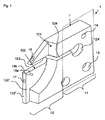
図1では、ホルダ本体1’は、冷却潤滑剤ダクトが、断面平面内に位置しないが、ホルダ本体1’内のより深い像平面の裏側に位置する縦断面で図示されている。ホルダ本体1’は、2つの部分、工作機械との連結のために設けられるクランプ部分11と、切削インサートを受容することができる受容部分12とを有する。
In FIG. 1, the holder body 1 'is illustrated in a longitudinal section in which the cooling lubricant duct is not located in the cross-sectional plane but is located behind the deeper image plane in the holder body 1'. The holder body 1 'has two parts, a clamping
突切り工具ホルダ1、すなわち、より正確にはホルダ本体1’は、受容されるべき所定の切削工具(例えば、両面とも使用可能な切削板)に対応するように形状および寸法が形成される切削工具座部123を有する。切削工具から突切り工具ホルダ1内への力の伝達を改善するために、切削工具座部123は、ホルダ本体1’の長手方向に対して横断方向に延びる溝状凹部を有することができる(しかしながら、この溝状凹部は図面には図示されていない)。スロット124の延在方向に対して垂直にホルダ本体にクランプ力を及ぼすクランプ装置により切削工具座部123に隣接するスロット124を弾性変形させる点において、切削工具を切削工具座部123内にクランプすることができる。スロット124の「閉鎖端部」には、末端孔124’が設けられ、この末端孔124’によって追加の弾力がもたらされかつ末端孔124’がスロットにおける応力集中を低減する。
The parting tool holder 1, ie more precisely the holder body 1 ', is shaped and dimensioned to correspond to a predetermined cutting tool to be received (eg a cutting plate that can be used on both sides). A
ホルダ本体1’は、ねじ孔(これは図面に図示されていない)であってもよい締結孔13を有する。ホルダ本体1’は、締結孔13によって工作機械に連結されて、直接または間接的に達成できる工作機械への力の伝達を可能にする。ホルダ本体1’は、旋盤の工具受容部に直接接続されるか、まずアダプタ内にクランプされるか、または細長い軸を備えた突切り工具ホルダの一部とすることができる。クランプ部分11において、ホルダ本体1’は、形成されるべき突切り溝の幅ができる限り小さくなるので、受容部分12における厚さよりも大きな厚さを有する。丸みの付いた部分121によって、回転本体のための十分な移動空間が設けられ、その一方で、受容部分12に剛性が付与される。
The holder body 1 'has a
その上、ホルダ本体1’は、工作機械の冷却潤滑剤システムに連結される冷却潤滑剤用の中央供給開口14を有する。冷却潤滑剤ダクト(これに関しては図2を参照)は、ホルダ本体1’内において供給開口14から離れる方向に延び、かつ出口開口16、17、18a、18b各々に開口する。突切り工具ホルダ1は、4つの出口開口16、17、18ab、18bを有する。1つの出口開口18a、18b各々は、切削工具座部123よりも下方の側面122”に位置するとともに表面から斜めに現れ、1つの出口開口18a、18b各々は互いに離れる方向を向いた壁部分に設けられる(これは、出口開口18bの破線表示で図示されている)。2つの出口開口16、17(切削工具座部123よりも上方に存在する上部出口開口16、切削工具座部123よりも下方に存在する下部出口開口17)は、ホルダ本体1’の端面122’に位置する。突切り工具ホルダ1が、異なる断面積および流量を有してもよい、いくつかの出口開口16、17、18a、18bを有するので、最適な切屑搬送および最適な冷却作用が達成される。下部端面出口開口17は、切削縁部を下方から冷却するために設計される一方で、上部端面出口開口16は切屑搬送にも役立ち、かつ側方出口開口18a、18bは、切削工具本体を下側方から冷却する。このことは、切削工具本体の加熱を防止することと、ホルダ本体1’への熱の伝導を防止することとに寄与する。流出する冷却媒体噴流Kの長手方向軸線は、点線で図示されている。
In addition, the holder body 1 'has a
図2は、断面表面が像平面内に位置する図1に図示する部分図の側面図を示している。冷却潤滑剤ダクト19、193、194、195の経路を説明できるように、隠れた縁部が破線で図示されている。冷却潤滑剤ダクト19は、中央供給点としての供給開口14から下方向に延び、かつスロット124に平行に延びるように切削工具座部123よりも下方に湾曲している。冷却潤滑剤ダクト19は、側面122’における側方出口開口18a、18bに開口する、冷却潤滑剤ダクト193と、端面122’における下部出口開口17に開口する、冷却潤滑剤ダクト195とに分岐する。分岐部191は、圧力損失を最小限に抑えるために流体的に有益な設計を有する。冷却潤滑剤ダクト194は、同じく供給開口14から離れる方向に延び、かつ端面122’の傾斜部分における上部出口開口16に開口する。
FIG. 2 shows a side view of the partial view shown in FIG. 1 where the cross-sectional surface is located in the image plane. The hidden edges are shown in broken lines so that the path of the cooling
例えば、鋳造および/またはフライス削り/穿孔などの、従来の1次成形および分離による製造方法では、記載したダクト幾何学形状を備えたホルダ本体1’を製造することができない。それゆえ、本発明によれば、最小限の機械的な後加工でホルダ本体1’を製造できるように、製造のための生産的製造方法、特に選択的レーザ溶融を使用することが提案される。ほぼ完成したホルダ本体は、選択的レーザ溶融用の装置から取り外すことができ、次いで、粉末状の出発材料の残留物を洗い落とした後に使用できる状態となる。 For example, conventional primary forming and separating manufacturing methods such as casting and / or milling / drilling cannot produce the holder body 1 'with the described duct geometry. Therefore, according to the invention, it is proposed to use a productive manufacturing method for manufacturing, in particular selective laser melting, so that the holder body 1 ′ can be manufactured with minimal mechanical post-processing. . The nearly complete holder body can be removed from the apparatus for selective laser melting and then ready for use after washing away the powdered starting material residue.
Claims (9)
切削工具座部(123)を備える板状ホルダ本体(1’)と、
前記突切り工具ホルダ(1)を工作機械内にクランプするためのクランプ部分(11)とを備え、
前記ホルダ本体の側面(122”)に少なくとも1つの出口開口(18a、18b)を備えるとともに前記側面(122”)から斜めに現れる少なくとも第1の冷却潤滑剤ダクト(193)が前記ホルダ本体(1’)内に存在し、
前記出口開口(18a、18b)が、前記冷却潤滑剤ダクト(193)から流出する冷却潤滑剤噴流(K)を前記切削工具座部(123)に受容される切削工具の表面上に側方から導くことができるように配向され、
前記ホルダ本体(1’)が、
前記ホルダ本体(1’)の端面(122’)に存在する上部出口開口(16)であって、冷却潤滑剤ダクト(194)から流出する冷却潤滑剤噴流を前記切削工具座部(123)に受容される切削工具の切削縁部に上方から導くことができるように配向される上部出口開口(16)に開口する少なくとも1つの上部冷却潤滑剤ダクト(194)と、
前記ホルダ本体(1’)の端面(122’)に存在する下部出口開口(17)であって、冷却潤滑剤ダクト(195)から流出する冷却潤滑剤噴流を前記切削工具座部(123)に受容される前記切削工具の前記切削縁部に下方から導くことができるように配向される下部出口開口(17)に開口する少なくとも1つの下部冷却潤滑剤ダクト(195)とを備える
ことを特徴とする、突切り工具ホルダ(1)。 A parting tool holder (1),
A plate-like holder body (1 ′) provided with a cutting tool seat (123);
A clamping part (11) for clamping the parting tool holder (1) in a machine tool,
The holder body has a side surface (122 ″) with at least one outlet opening (18a, 18b) and at least a first cooling lubricant duct (193) that appears obliquely from the side surface (122 ″). ') Exists in
The outlet openings (18a, 18b) are laterally on the surface of the cutting tool that receives the cooling lubricant jet (K) flowing out of the cooling lubricant duct (193) in the cutting tool seat (123). Oriented so that it can be guided,
The holder body (1 ′)
An upper outlet opening (16) existing on an end surface (122 ') of the holder body (1'), and a cooling lubricant jet flowing out from a cooling lubricant duct (194) is passed to the cutting tool seat (123). At least one upper cooling lubricant duct (194) that opens into an upper outlet opening (16) that is oriented so that it can be directed from above to the cutting edge of the received cutting tool;
A coolant outlet jet (17) existing in the end surface (122 ') of the holder body (1') and flowing out from the coolant lubricant duct (195) is transferred to the cutting tool seat (123). At least one lower cooling lubricant duct (195) that opens into a lower outlet opening (17) that is oriented so that it can be guided from below into the cutting edge of the received cutting tool. Cut-off tool holder (1).
前記冷却潤滑剤ダクト(193、194、195)の少なくとも1つが、非円形断面、好ましくは楕円形断面もしくは矩形断面、最も好ましくは扁平な楕円形断面もしくは扁平な矩形断面を有することを特徴とする、請求項1〜3のいずれか一項に記載の突切り工具ホルダ(1)。 The upper cooling lubricant duct (194) and / or the lower cooling lubricant duct (195) arise from a common cooling lubricant duct part, in particular a branch of the first cooling lubricant duct (19, 193). And / or at least one of the cooling lubricant ducts (193, 194, 195) has a non-circular cross section, preferably an elliptical cross section or a rectangular cross section, most preferably a flat elliptical cross section or a flat rectangular cross section. Cut-off tool holder (1) according to any one of the preceding claims, characterized in that
b)粉末状の出発材料を準備するステップと、
c)粉末状の前記出発材料の材料凝集を段階的に生じさせ、それにより、前記板状ホルダ本体体積(1’)を段階的に製造するステップであって、
少なくとも1つの出口開口(18a、18b)を備える、側面(122”)から斜めに前記ホルダ本体の前記側面(122”)に現れる前記少なくとも第1の冷却潤滑剤ダクト(193)を備え、かつ
前記ホルダ本体(1’)の端面(122’)に存在する上部出口開口(16)に開口する前記少なくとも1つの上部冷却潤滑剤ダクト(194)を備え、かつ
前記ホルダ本体(1’)の端面(122’)に存在する下部出口開口(17)に開口する前記少なくとも1つの下部冷却潤滑剤ダクト(195)を備える、ステップと
を含む、生産的加工装置を使用することによる、請求項1〜5のいずれか一項に記載の突切り工具ホルダ(1)用の製造方法。 a) loading a three-dimensional volume data set describing a holder body (1 ′) of said parting tool holder (1) into a productive processing device;
b) preparing a powdery starting material;
c) staging the material aggregation of the starting material in powder form, thereby producing the plate-like holder body volume (1 ′) in stages,
Comprising at least a first cooling lubricant duct (193) that appears at an angle from a side (122 '') to the side (122 '') of the holder body, comprising at least one outlet opening (18a, 18b); Comprising at least one upper cooling lubricant duct (194) opening in an upper outlet opening (16) present in an end face (122 ') of the holder body (1'), and an end face of the holder body (1 ') ( By using a productive processing apparatus comprising the at least one lower cooling lubricant duct (195) opening to a lower outlet opening (17) present at 122 '). The manufacturing method for the cut-off tool holder (1) as described in any one of these.
前記生産的加工装置が、選択的レーザ溶融または選択的レーザ焼結用の装置であることを特徴とする、請求項6または7に記載の製造方法。 8. The powdery starting material is a metal powder and / or the productive processing device is a device for selective laser melting or selective laser sintering. Manufacturing method.
Applications Claiming Priority (3)
| Application Number | Priority Date | Filing Date | Title |
|---|---|---|---|
| EP14000278.3 | 2014-01-27 | ||
| EP14000278.3A EP2898967B9 (en) | 2014-01-27 | 2014-01-27 | Cutting tool holder, production method and use of a generative manufacturing device for manufacturing the cutting tool holder |
| PCT/EP2014/003238 WO2015110132A1 (en) | 2014-01-27 | 2014-12-04 | Cut-off tool holder and production method |
Publications (2)
| Publication Number | Publication Date |
|---|---|
| JP2017503669A true JP2017503669A (en) | 2017-02-02 |
| JP6412580B2 JP6412580B2 (en) | 2018-10-24 |
Family
ID=50028723
Family Applications (1)
| Application Number | Title | Priority Date | Filing Date |
|---|---|---|---|
| JP2016547945A Active JP6412580B2 (en) | 2014-01-27 | 2014-12-04 | Parting tool holder and manufacturing method |
Country Status (5)
| Country | Link |
|---|---|
| US (1) | US20160339523A1 (en) |
| EP (1) | EP2898967B9 (en) |
| JP (1) | JP6412580B2 (en) |
| IL (1) | IL246906B (en) |
| WO (1) | WO2015110132A1 (en) |
Cited By (4)
| Publication number | Priority date | Publication date | Assignee | Title |
|---|---|---|---|---|
| WO2018221162A1 (en) * | 2017-06-01 | 2018-12-06 | 日本特殊陶業株式会社 | Cutting tool holder and cutting tool |
| JP2020066104A (en) * | 2018-10-25 | 2020-04-30 | Dmg森精機株式会社 | Machine tool manufacturing method, and manufacturing system |
| JP2020163526A (en) * | 2019-03-29 | 2020-10-08 | 三菱マテリアル株式会社 | Head member for grooving tool, and grooving tool |
| JP2020535029A (en) * | 2017-10-12 | 2020-12-03 | ハルトメタル−ウェルクゾーグファブリック ポール ホーン ゲゼルシャフト ミット ベシュレンクテル ハフツング | Broach tool holder |
Families Citing this family (18)
| Publication number | Priority date | Publication date | Assignee | Title |
|---|---|---|---|---|
| DE102014119295B4 (en) | 2014-12-19 | 2023-08-10 | Kennametal Inc. | Tool holder for a cutting insert and method for manufacturing the tool holder |
| JP6550759B2 (en) * | 2015-01-23 | 2019-07-31 | 三菱マテリアル株式会社 | Part-Time Job |
| US10507529B2 (en) * | 2015-07-24 | 2019-12-17 | Kyocera Corporation | Cutting tool and method of manufacturing machined product using the same |
| WO2017110903A1 (en) * | 2015-12-25 | 2017-06-29 | 京セラ株式会社 | Cutting tool holder, cutting tool, and method for manufacturing cut workpiece |
| US10201862B2 (en) * | 2016-09-07 | 2019-02-12 | Iscar, Ltd. | Cutting tool having a coolant chamber with an integrally formed coolant deflection portion and tool body |
| EP3219421A1 (en) * | 2016-09-09 | 2017-09-20 | Seco Tools Ab | Toolholders with fluid supply conduits for supercritical co2 |
| DE102016120595A1 (en) * | 2016-10-27 | 2018-05-03 | Komet Group Gmbh | cutting tool |
| DE102017110132A1 (en) * | 2017-05-10 | 2018-11-15 | Kennametal Inc. | Abstechdrehwerkzeug |
| US10300532B2 (en) * | 2017-06-26 | 2019-05-28 | Kennametal Inc. | Clamp for tool holder |
| CN107999797B (en) * | 2017-11-30 | 2019-05-03 | 株洲钻石切削刀具股份有限公司 | A kind of grooving cutter and inner cooling path processing method with inner cooling path |
| US11491594B2 (en) | 2018-01-08 | 2022-11-08 | Ford Motor Company | Tooling assembly with internal coolant passages for machines |
| WO2020065976A1 (en) * | 2018-09-28 | 2020-04-02 | Sumitomo Electric Hardmetal Corp. | Cutting tool, turning tool and method of working on a workpiece |
| WO2020078997A1 (en) * | 2018-10-17 | 2020-04-23 | Hartmetall-Werkzeugfabrik Paul Horn Gmbh | Tool holder and tool having a tool holder of this kind |
| DE102018125767A1 (en) * | 2018-10-17 | 2020-04-23 | Hartmetall-Werkzeugfabrik Paul Horn Gmbh | Tool holder and tool with such a tool holder |
| JP2023530585A (en) * | 2020-06-30 | 2023-07-19 | イスカル リミテッド | Indexable parting blade with circuit coolant passage |
| CZ2020594A3 (en) * | 2020-11-03 | 2022-06-01 | Západočeská Univerzita V Plzni | Machining tool |
| DE102021207539A1 (en) * | 2021-07-15 | 2023-01-19 | Karl-Heinz Arnold Gmbh | Process for manufacturing turning tools and turning tool |
| CZ309545B6 (en) * | 2021-12-23 | 2023-03-29 | Západočeská Univerzita V Plzni | Machining tool |
Citations (6)
| Publication number | Priority date | Publication date | Assignee | Title |
|---|---|---|---|---|
| JPS48107176U (en) * | 1972-03-16 | 1973-12-12 | ||
| JPH0683205U (en) * | 1993-03-25 | 1994-11-29 | 京セラ株式会社 | Tool holder for turning |
| JPH11291101A (en) * | 1998-04-13 | 1999-10-26 | Mitsubishi Materials Corp | Cutting tool with oil hole |
| US20070283786A1 (en) * | 2006-06-09 | 2007-12-13 | Gregor Kappmeyer | Mehod for the manufacture of a cutting tool |
| WO2012130857A1 (en) * | 2011-03-28 | 2012-10-04 | Hartmetall-Werkzeugfabrik Paul Horn Gmbh | Tool for the machining of a workpiece with lateral coolant outlet |
| JP2013194263A (en) * | 2012-03-16 | 2013-09-30 | Panasonic Corp | Method of manufacturing three-dimensionally shaped object |
Family Cites Families (21)
| Publication number | Priority date | Publication date | Assignee | Title |
|---|---|---|---|---|
| US3798725A (en) | 1969-04-24 | 1974-03-26 | T Hanson | Cutting tool |
| SE354213B (en) * | 1972-04-10 | 1973-03-05 | Sandvik Ab | |
| US4863538A (en) | 1986-10-17 | 1989-09-05 | Board Of Regents, The University Of Texas System | Method and apparatus for producing parts by selective sintering |
| DE10252040B3 (en) * | 2002-11-06 | 2004-01-22 | Manfred Scharmann | Thread cutting tool |
| JPH07227702A (en) | 1994-02-22 | 1995-08-29 | Mitsubishi Materials Corp | Tool for grooving |
| IL115544A (en) | 1995-10-06 | 1998-12-06 | Iscar Ltd | Cutting tool assembly having an exchangeable adaptor |
| JPH1076404A (en) * | 1996-02-28 | 1998-03-24 | Sumitomo Electric Ind Ltd | Cutting tool for lathe turning |
| DE19649865C1 (en) | 1996-12-02 | 1998-02-12 | Fraunhofer Ges Forschung | Shaped body especially prototype or replacement part production |
| SE0100652L (en) | 2001-02-27 | 2002-08-28 | Sandvik Ab | Process for chip separating machining and cutting tool for chip separating machining |
| WO2004056519A2 (en) | 2002-12-19 | 2004-07-08 | Gühring, Jörg | Cooling channel geometry |
| SE526255C2 (en) † | 2003-03-14 | 2005-08-09 | Sandvik Intellectual Property | Tools and indexable inserts for fine turning of rotationally symmetrical grooves in workpieces |
| DE102004032093B4 (en) | 2004-07-01 | 2007-05-16 | Cl Schutzrechtsverwaltungs Gmbh | Component produced by a selective laser sintering process (SLS) |
| NO330162B1 (en) * | 2006-06-28 | 2011-02-28 | Teeness Asa | Container for insertion into a tool holder, a tool holder and a system |
| SE530581C2 (en) | 2006-11-28 | 2008-07-08 | Sandvik Intellectual Property | Chip separation tool and basic body comprising two channels for a fluid |
| JP5559470B2 (en) | 2008-10-29 | 2014-07-23 | 三菱マテリアル株式会社 | Inner diameter machining tool and inner diameter machining method |
| JP5501598B2 (en) | 2008-10-29 | 2014-05-21 | 京セラ株式会社 | Holder, cutting tool using the same, and cutting method using the same |
| US8388268B2 (en) | 2011-03-07 | 2013-03-05 | Kennametal Inc. | Cutting assembly |
| KR101243280B1 (en) | 2011-04-28 | 2013-03-13 | 주식회사 인스텍 | Metal Product Having Internal Space And Method of Manufacturing The Same |
| PT3103573T (en) | 2012-03-06 | 2023-09-11 | Iscar Ltd | Parting blade and blade holder configured for conveyance of pressurized coolant |
| DE202012004900U1 (en) | 2012-05-18 | 2012-06-15 | Karl-Heinz Arnold Gmbh | cutting tool |
| SE1350795A1 (en) | 2013-06-28 | 2014-12-29 | Sandvik Intellectual Property | Tools for chip separating machining as well as cutting blade and interchangeable cutter for this. |
-
2014
- 2014-01-27 EP EP14000278.3A patent/EP2898967B9/en active Active
- 2014-12-04 WO PCT/EP2014/003238 patent/WO2015110132A1/en active Application Filing
- 2014-12-04 US US15/113,975 patent/US20160339523A1/en not_active Abandoned
- 2014-12-04 JP JP2016547945A patent/JP6412580B2/en active Active
-
2016
- 2016-07-24 IL IL246906A patent/IL246906B/en active IP Right Grant
Patent Citations (6)
| Publication number | Priority date | Publication date | Assignee | Title |
|---|---|---|---|---|
| JPS48107176U (en) * | 1972-03-16 | 1973-12-12 | ||
| JPH0683205U (en) * | 1993-03-25 | 1994-11-29 | 京セラ株式会社 | Tool holder for turning |
| JPH11291101A (en) * | 1998-04-13 | 1999-10-26 | Mitsubishi Materials Corp | Cutting tool with oil hole |
| US20070283786A1 (en) * | 2006-06-09 | 2007-12-13 | Gregor Kappmeyer | Mehod for the manufacture of a cutting tool |
| WO2012130857A1 (en) * | 2011-03-28 | 2012-10-04 | Hartmetall-Werkzeugfabrik Paul Horn Gmbh | Tool for the machining of a workpiece with lateral coolant outlet |
| JP2013194263A (en) * | 2012-03-16 | 2013-09-30 | Panasonic Corp | Method of manufacturing three-dimensionally shaped object |
Cited By (9)
| Publication number | Priority date | Publication date | Assignee | Title |
|---|---|---|---|---|
| WO2018221162A1 (en) * | 2017-06-01 | 2018-12-06 | 日本特殊陶業株式会社 | Cutting tool holder and cutting tool |
| JP2018202530A (en) * | 2017-06-01 | 2018-12-27 | 日本特殊陶業株式会社 | Cutting tool holder and cutting tool |
| JP2020535029A (en) * | 2017-10-12 | 2020-12-03 | ハルトメタル−ウェルクゾーグファブリック ポール ホーン ゲゼルシャフト ミット ベシュレンクテル ハフツング | Broach tool holder |
| JP7026212B2 (en) | 2017-10-12 | 2022-02-25 | ハルトメタル-ウェルクゾーグファブリック ポール ホーン ゲゼルシャフト ミット ベシュレンクテル ハフツング | Broach tool holder |
| US11648613B2 (en) | 2017-10-12 | 2023-05-16 | Hartmetall-Werkzeugfabrik Paul Hom GmbH | Holder for a broaching tool |
| JP2020066104A (en) * | 2018-10-25 | 2020-04-30 | Dmg森精機株式会社 | Machine tool manufacturing method, and manufacturing system |
| JP7058207B2 (en) | 2018-10-25 | 2022-04-21 | Dmg森精機株式会社 | Machine tool manufacturing method and manufacturing system |
| JP2020163526A (en) * | 2019-03-29 | 2020-10-08 | 三菱マテリアル株式会社 | Head member for grooving tool, and grooving tool |
| JP7183916B2 (en) | 2019-03-29 | 2022-12-06 | 三菱マテリアル株式会社 | Head member for grooving tool and grooving tool |
Also Published As
| Publication number | Publication date |
|---|---|
| EP2898967A1 (en) | 2015-07-29 |
| EP2898967B1 (en) | 2017-01-25 |
| JP6412580B2 (en) | 2018-10-24 |
| US20160339523A1 (en) | 2016-11-24 |
| IL246906A0 (en) | 2016-09-29 |
| IL246906B (en) | 2020-05-31 |
| WO2015110132A1 (en) | 2015-07-30 |
| EP2898967B9 (en) | 2021-08-11 |
| EP2898967B2 (en) | 2021-03-03 |
Similar Documents
| Publication | Publication Date | Title |
|---|---|---|
| JP6412580B2 (en) | Parting tool holder and manufacturing method | |
| US20170252839A1 (en) | Side Milling Cutter and Production Method | |
| US9931699B2 (en) | Cutting tool holder and cutting tool | |
| JP6753871B2 (en) | How to cut fiber reinforced polymer composite work piece with pure water jet | |
| Vagnorius et al. | Effect of high-pressure cooling on life of SiAlON tools in machining of Inconel 718 | |
| EP1614497A1 (en) | Method and apparatus for repairing or building up surfaces on a workpiece while the workpiece is mounted on a machine tool | |
| Najiha et al. | Investigation of flow behavior in minimum quantity lubrication nozzle for end milling processes | |
| KR20140002625A (en) | Cutting tools and cutting inserts including internal cooling | |
| US9937598B2 (en) | Cover for cutting tool, holder for cutting, and cutting device | |
| RU2420393C2 (en) | Tool to make parts from composite materials | |
| JP6850807B2 (en) | Metal cutting tool holder including fluid passage | |
| GB2501511A (en) | Cutting tool with internal mql supply | |
| JP2020500723A (en) | Anvil with curved path for cutting tools | |
| JP2017225908A (en) | Liquid discharge pipe structure | |
| KR101342479B1 (en) | cutting tool holder of Computer Numerical Control Lathe | |
| JP6652576B2 (en) | Manufacturing method of cutting tool and cut workpiece | |
| US11491594B2 (en) | Tooling assembly with internal coolant passages for machines | |
| Webster | Improving surface integrity and economics of grinding by optimum coolant application, with consideration of abrasive tool and process regime | |
| JP4702902B2 (en) | Sharpening tool and sharpening method | |
| CN103084643A (en) | Improved milling cutter | |
| RU198358U1 (en) | Drilling tool | |
| JP2017136661A (en) | Cutting tool, processing device having cutting tool, and processing method using cutting tool | |
| US8413680B2 (en) | Fluid distribution apparatus | |
| KR20140103383A (en) | Machine tool with flushing apparatus | |
| Webster et al. | Improving grinding process economics through more effective fluid application |
Legal Events
| Date | Code | Title | Description |
|---|---|---|---|
| A621 | Written request for application examination |
Free format text: JAPANESE INTERMEDIATE CODE: A621 Effective date: 20170412 |
|
| A131 | Notification of reasons for refusal |
Free format text: JAPANESE INTERMEDIATE CODE: A131 Effective date: 20180313 |
|
| A977 | Report on retrieval |
Free format text: JAPANESE INTERMEDIATE CODE: A971007 Effective date: 20180314 |
|
| A521 | Request for written amendment filed |
Free format text: JAPANESE INTERMEDIATE CODE: A523 Effective date: 20180613 |
|
| TRDD | Decision of grant or rejection written | ||
| A01 | Written decision to grant a patent or to grant a registration (utility model) |
Free format text: JAPANESE INTERMEDIATE CODE: A01 Effective date: 20180904 |
|
| A61 | First payment of annual fees (during grant procedure) |
Free format text: JAPANESE INTERMEDIATE CODE: A61 Effective date: 20180928 |
|
| R150 | Certificate of patent or registration of utility model |
Ref document number: 6412580 Country of ref document: JP Free format text: JAPANESE INTERMEDIATE CODE: R150 |
|
| R250 | Receipt of annual fees |
Free format text: JAPANESE INTERMEDIATE CODE: R250 |
|
| R250 | Receipt of annual fees |
Free format text: JAPANESE INTERMEDIATE CODE: R250 |