JP2017503174A - Structure and method for indicating undesirable components in a fuel cell system - Google Patents
Structure and method for indicating undesirable components in a fuel cell system Download PDFInfo
- Publication number
- JP2017503174A JP2017503174A JP2016544115A JP2016544115A JP2017503174A JP 2017503174 A JP2017503174 A JP 2017503174A JP 2016544115 A JP2016544115 A JP 2016544115A JP 2016544115 A JP2016544115 A JP 2016544115A JP 2017503174 A JP2017503174 A JP 2017503174A
- Authority
- JP
- Japan
- Prior art keywords
- fuel
- sorbent bed
- sensor
- fuel cell
- detector
- Prior art date
- Legal status (The legal status is an assumption and is not a legal conclusion. Google has not performed a legal analysis and makes no representation as to the accuracy of the status listed.)
- Pending
Links
Images


Classifications
-
- H—ELECTRICITY
- H01—ELECTRIC ELEMENTS
- H01M—PROCESSES OR MEANS, e.g. BATTERIES, FOR THE DIRECT CONVERSION OF CHEMICAL ENERGY INTO ELECTRICAL ENERGY
- H01M8/00—Fuel cells; Manufacture thereof
- H01M8/04—Auxiliary arrangements, e.g. for control of pressure or for circulation of fluids
- H01M8/04298—Processes for controlling fuel cells or fuel cell systems
- H01M8/04694—Processes for controlling fuel cells or fuel cell systems characterised by variables to be controlled
- H01M8/04746—Pressure; Flow
- H01M8/04753—Pressure; Flow of fuel cell reactants
-
- G—PHYSICS
- G01—MEASURING; TESTING
- G01N—INVESTIGATING OR ANALYSING MATERIALS BY DETERMINING THEIR CHEMICAL OR PHYSICAL PROPERTIES
- G01N33/00—Investigating or analysing materials by specific methods not covered by groups G01N1/00 - G01N31/00
- G01N33/48—Biological material, e.g. blood, urine; Haemocytometers
- G01N33/50—Chemical analysis of biological material, e.g. blood, urine; Testing involving biospecific ligand binding methods; Immunological testing
- G01N33/52—Use of compounds or compositions for colorimetric, spectrophotometric or fluorometric investigation, e.g. use of reagent paper and including single- and multilayer analytical elements
-
- H—ELECTRICITY
- H01—ELECTRIC ELEMENTS
- H01M—PROCESSES OR MEANS, e.g. BATTERIES, FOR THE DIRECT CONVERSION OF CHEMICAL ENERGY INTO ELECTRICAL ENERGY
- H01M8/00—Fuel cells; Manufacture thereof
- H01M8/04—Auxiliary arrangements, e.g. for control of pressure or for circulation of fluids
- H01M8/04082—Arrangements for control of reactant parameters, e.g. pressure or concentration
- H01M8/04089—Arrangements for control of reactant parameters, e.g. pressure or concentration of gaseous reactants
-
- H—ELECTRICITY
- H01—ELECTRIC ELEMENTS
- H01M—PROCESSES OR MEANS, e.g. BATTERIES, FOR THE DIRECT CONVERSION OF CHEMICAL ENERGY INTO ELECTRICAL ENERGY
- H01M8/00—Fuel cells; Manufacture thereof
- H01M8/04—Auxiliary arrangements, e.g. for control of pressure or for circulation of fluids
- H01M8/04082—Arrangements for control of reactant parameters, e.g. pressure or concentration
- H01M8/04201—Reactant storage and supply, e.g. means for feeding, pipes
-
- H—ELECTRICITY
- H01—ELECTRIC ELEMENTS
- H01M—PROCESSES OR MEANS, e.g. BATTERIES, FOR THE DIRECT CONVERSION OF CHEMICAL ENERGY INTO ELECTRICAL ENERGY
- H01M8/00—Fuel cells; Manufacture thereof
- H01M8/04—Auxiliary arrangements, e.g. for control of pressure or for circulation of fluids
- H01M8/04298—Processes for controlling fuel cells or fuel cell systems
- H01M8/04313—Processes for controlling fuel cells or fuel cell systems characterised by the detection or assessment of variables; characterised by the detection or assessment of failure or abnormal function
- H01M8/0438—Pressure; Ambient pressure; Flow
- H01M8/04388—Pressure; Ambient pressure; Flow of anode reactants at the inlet or inside the fuel cell
-
- H—ELECTRICITY
- H01—ELECTRIC ELEMENTS
- H01M—PROCESSES OR MEANS, e.g. BATTERIES, FOR THE DIRECT CONVERSION OF CHEMICAL ENERGY INTO ELECTRICAL ENERGY
- H01M8/00—Fuel cells; Manufacture thereof
- H01M8/04—Auxiliary arrangements, e.g. for control of pressure or for circulation of fluids
- H01M8/04298—Processes for controlling fuel cells or fuel cell systems
- H01M8/04313—Processes for controlling fuel cells or fuel cell systems characterised by the detection or assessment of variables; characterised by the detection or assessment of failure or abnormal function
- H01M8/0444—Concentration; Density
- H01M8/04447—Concentration; Density of anode reactants at the inlet or inside the fuel cell
-
- H—ELECTRICITY
- H01—ELECTRIC ELEMENTS
- H01M—PROCESSES OR MEANS, e.g. BATTERIES, FOR THE DIRECT CONVERSION OF CHEMICAL ENERGY INTO ELECTRICAL ENERGY
- H01M8/00—Fuel cells; Manufacture thereof
- H01M8/04—Auxiliary arrangements, e.g. for control of pressure or for circulation of fluids
- H01M8/04298—Processes for controlling fuel cells or fuel cell systems
- H01M8/04313—Processes for controlling fuel cells or fuel cell systems characterised by the detection or assessment of variables; characterised by the detection or assessment of failure or abnormal function
- H01M8/04537—Electric variables
- H01M8/04544—Voltage
- H01M8/04559—Voltage of fuel cell stacks
-
- H—ELECTRICITY
- H01—ELECTRIC ELEMENTS
- H01M—PROCESSES OR MEANS, e.g. BATTERIES, FOR THE DIRECT CONVERSION OF CHEMICAL ENERGY INTO ELECTRICAL ENERGY
- H01M8/00—Fuel cells; Manufacture thereof
- H01M8/04—Auxiliary arrangements, e.g. for control of pressure or for circulation of fluids
- H01M8/04298—Processes for controlling fuel cells or fuel cell systems
- H01M8/04313—Processes for controlling fuel cells or fuel cell systems characterised by the detection or assessment of variables; characterised by the detection or assessment of failure or abnormal function
- H01M8/04664—Failure or abnormal function
- H01M8/04686—Failure or abnormal function of auxiliary devices, e.g. batteries, capacitors
-
- H—ELECTRICITY
- H01—ELECTRIC ELEMENTS
- H01M—PROCESSES OR MEANS, e.g. BATTERIES, FOR THE DIRECT CONVERSION OF CHEMICAL ENERGY INTO ELECTRICAL ENERGY
- H01M8/00—Fuel cells; Manufacture thereof
- H01M8/04—Auxiliary arrangements, e.g. for control of pressure or for circulation of fluids
- H01M8/04298—Processes for controlling fuel cells or fuel cell systems
- H01M8/04694—Processes for controlling fuel cells or fuel cell systems characterised by variables to be controlled
- H01M8/04746—Pressure; Flow
- H01M8/04776—Pressure; Flow at auxiliary devices, e.g. reformer, compressor, burner
-
- H—ELECTRICITY
- H01—ELECTRIC ELEMENTS
- H01M—PROCESSES OR MEANS, e.g. BATTERIES, FOR THE DIRECT CONVERSION OF CHEMICAL ENERGY INTO ELECTRICAL ENERGY
- H01M8/00—Fuel cells; Manufacture thereof
- H01M8/06—Combination of fuel cells with means for production of reactants or for treatment of residues
- H01M8/0662—Treatment of gaseous reactants or gaseous residues, e.g. cleaning
- H01M8/0675—Removal of sulfur
-
- H—ELECTRICITY
- H01—ELECTRIC ELEMENTS
- H01M—PROCESSES OR MEANS, e.g. BATTERIES, FOR THE DIRECT CONVERSION OF CHEMICAL ENERGY INTO ELECTRICAL ENERGY
- H01M8/00—Fuel cells; Manufacture thereof
- H01M8/06—Combination of fuel cells with means for production of reactants or for treatment of residues
- H01M8/0662—Treatment of gaseous reactants or gaseous residues, e.g. cleaning
- H01M8/0687—Reactant purification by the use of membranes or filters
-
- H—ELECTRICITY
- H01—ELECTRIC ELEMENTS
- H01M—PROCESSES OR MEANS, e.g. BATTERIES, FOR THE DIRECT CONVERSION OF CHEMICAL ENERGY INTO ELECTRICAL ENERGY
- H01M8/00—Fuel cells; Manufacture thereof
- H01M8/10—Fuel cells with solid electrolytes
- H01M8/12—Fuel cells with solid electrolytes operating at high temperature, e.g. with stabilised ZrO2 electrolyte
- H01M2008/1293—Fuel cells with solid oxide electrolytes
-
- Y—GENERAL TAGGING OF NEW TECHNOLOGICAL DEVELOPMENTS; GENERAL TAGGING OF CROSS-SECTIONAL TECHNOLOGIES SPANNING OVER SEVERAL SECTIONS OF THE IPC; TECHNICAL SUBJECTS COVERED BY FORMER USPC CROSS-REFERENCE ART COLLECTIONS [XRACs] AND DIGESTS
- Y02—TECHNOLOGIES OR APPLICATIONS FOR MITIGATION OR ADAPTATION AGAINST CLIMATE CHANGE
- Y02E—REDUCTION OF GREENHOUSE GAS [GHG] EMISSIONS, RELATED TO ENERGY GENERATION, TRANSMISSION OR DISTRIBUTION
- Y02E60/00—Enabling technologies; Technologies with a potential or indirect contribution to GHG emissions mitigation
- Y02E60/30—Hydrogen technology
- Y02E60/50—Fuel cells
-
- Y—GENERAL TAGGING OF NEW TECHNOLOGICAL DEVELOPMENTS; GENERAL TAGGING OF CROSS-SECTIONAL TECHNOLOGIES SPANNING OVER SEVERAL SECTIONS OF THE IPC; TECHNICAL SUBJECTS COVERED BY FORMER USPC CROSS-REFERENCE ART COLLECTIONS [XRACs] AND DIGESTS
- Y10—TECHNICAL SUBJECTS COVERED BY FORMER USPC
- Y10T—TECHNICAL SUBJECTS COVERED BY FORMER US CLASSIFICATION
- Y10T436/00—Chemistry: analytical and immunological testing
- Y10T436/18—Sulfur containing
Abstract
燃料電池システムにおいて望ましくない成分を検出するための光学検出システムは、望ましくない成分が存在すると変色するように構成された感知材料と、感知材料の変色を示すように構成された少なくとも1つのセンサとを備える。このセンサは、対応する光源に結合される。感知材料、センサおよび光源はハウジングに封入される。An optical detection system for detecting an undesirable component in a fuel cell system includes a sensing material configured to change color when the undesirable component is present, and at least one sensor configured to indicate a color change of the sensing material. Is provided. This sensor is coupled to a corresponding light source. The sensing material, sensor and light source are enclosed in a housing.
Description
本発明は、燃料電池システムにおける望ましくない成分を示すための構造および方法に関する。 The present invention relates to structures and methods for indicating undesirable components in fuel cell systems.
関連特許出願の相互参照
本願は、その全体が本願明細書において参照により援用されている、「燃料電池システムにおける望ましくない成分を示すための構造および方法」という2014年1月6日に出願された米国仮特許出願第61/923,886号明細書(特許件文献1)に対する優先権の利益を主張する。
CROSS REFERENCE TO RELATED PATENT APPLICATIONS This application was filed on January 6, 2014, “Structures and Methods for Determining Undesirable Components in a Fuel Cell System,” which is incorporated herein by reference in its entirety. Claims the benefit of priority over US Provisional Patent Application No. 61 / 923,886 (Patent Document 1).
固体酸化物形燃料電池(SOFC)システムなどの燃料電池システムの信頼性は、燃料流の中の望ましくない成分の存在および濃度に大きく依存する。水分、酸素、シロキサン、および硫黄(硫黄化合物を含む)などの望ましくない成分は、燃料電池スタックの性能を低下させ、効率の低下および費用のかかる交換という結果をもたらす回復不能なダメージの原因となることがある。特に、燃料として天然ガスを使用するとき、燃料電池システムは、例えば硫黄および硫黄化合物、シロキサン、水分などを除去するためにガス浄化を必要とする。燃料を収着剤ベッドに通すことは、燃料電池で使用する前の燃料から天然ガスを浄化する1つの方法である。しかし、収着剤ベッド(例えば、脱硫吸着ベッド)は有限の寿命を有し、いったん収着剤ベッドが消尽されてしまえば、硫黄は吸収されずに収着剤ベッドを通過して燃料電池スタックに到達し、永久的なダメージを引き起こす可能性がある。収着剤ベッドが消尽される前に交換されたとしても、収着剤ベッドには十分に活用されていない部分が存在することがあって、収着剤ベッド交換のコストを高める。さらに、ガス浄化収着剤ベッドによって濾過されない他の望ましくない成分は、燃料電池スタックに対するダメージを引き起こしてその運転寿命を縮めることがある。 The reliability of a fuel cell system, such as a solid oxide fuel cell (SOFC) system, is highly dependent on the presence and concentration of undesirable components in the fuel stream. Undesirable components such as moisture, oxygen, siloxane, and sulfur (including sulfur compounds) reduce the performance of the fuel cell stack and cause irreparable damage that results in reduced efficiency and costly replacement Sometimes. In particular, when using natural gas as fuel, fuel cell systems require gas purification to remove, for example, sulfur and sulfur compounds, siloxanes, moisture, and the like. Passing fuel through a sorbent bed is one way to purify natural gas from fuel prior to use in a fuel cell. However, sorbent beds (eg, desulfurization adsorbent beds) have a finite lifetime, and once the sorbent bed is exhausted, the sulfur is not absorbed and passes through the sorbent bed to the fuel cell stack. May cause permanent damage. Even if the sorbent bed is replaced before it is exhausted, there may be a portion of the sorbent bed that is not fully utilized, increasing the cost of replacing the sorbent bed. In addition, other undesirable components that are not filtered by the gas purification sorbent bed can cause damage to the fuel cell stack and shorten its operating life.
種々の実施形態が、燃料電池システムにおいて望ましくない成分を検出するための光学検出システムを提供する。その光学検出システムは、望ましくない成分が存在すると変色するように構成された感知材料と、感知材料の変色を示すように構成された少なくとも1つのセンサとを備えることができ、その感知材料およびセンサはハウジングに封入される。 Various embodiments provide an optical detection system for detecting undesirable components in a fuel cell system. The optical detection system can comprise a sensing material configured to change color in the presence of an undesirable component and at least one sensor configured to indicate a color change of the sensing material, the sensing material and sensor Is enclosed in a housing.
いくつかの実施形態は、望ましくない成分が存在すると変色するように構成された感知材料を含む光学検出システムを提供することによって、燃料電池システムにおいて望ましくない成分を検出する方法を提供する。このような実施形態の方法は、感知材料を光源からの光で照明するステップと、センサを用いて感知材料において変色が起こっているか否かを判定するステップと、感知材料において変色が起こっていると判定するステップに応答して、燃料電池システムの燃料流の中の望ましくない成分の存在を検出するステップと、望ましくない成分の存在に基づいてアラーム基準が満たされたときにアラーム信号を生成するステップとを含むことができる。 Some embodiments provide a method of detecting unwanted components in a fuel cell system by providing an optical detection system that includes a sensing material configured to change color when an unwanted component is present. The method of such an embodiment includes illuminating the sensing material with light from a light source, determining whether a color change is occurring in the sensing material using a sensor, and causing the color change in the sensing material. In response to determining the presence of an undesirable component in the fuel flow of the fuel cell system and generating an alarm signal when an alarm criterion is met based on the presence of the undesirable component Steps.
このような実施形態の方法は、感知材料の変色を示すように構成された少なくとも1つの成分センサと、望ましくない成分が存在しても変色しないように構成された基準材料と、基準材料の変色を示すように構成された基準センサとをも備える光学検出システムを設けるステップを含むことができる。このような実施形態の方法は、感知材料の変色と基準材料との差に基づいて燃料電池システムの燃料流の中の望ましくない成分を検出するステップと、アラーム基準が満たされたときにアラーム信号を生成するステップとを含むことができる。 The method of such an embodiment includes at least one component sensor configured to indicate a discoloration of the sensing material, a reference material configured to not discolor in the presence of an undesirable component, and a discoloration of the reference material Providing an optical detection system also comprising a reference sensor configured to indicate The method of such an embodiment includes detecting an undesired component in the fuel flow of the fuel cell system based on the difference between the discoloration of the sensing material and the reference material, and an alarm signal when the alarm criteria are met. Generating.
種々の実施形態の光学検出システムにおいて、センサを対応する光源に接続することができる。このような実施形態の光学検出システムは、望ましくない成分が存在しても変色しない基準材料と、基準材料の変色を示すように構成された基準センサとをも備えることができ、基準センサは光学的に光源に接続される。 In the optical detection system of various embodiments, the sensor can be connected to a corresponding light source. The optical detection system of such an embodiment can also include a reference material that does not change color in the presence of undesirable components, and a reference sensor configured to indicate a color change of the reference material, the reference sensor being optical. Connected to the light source.
このような実施形態の方法は、赤色センサ、緑色センサおよび青色センサを含む少なくとも1つのセンサと、各色センサからの色値を受け取るように構成されたプロセッサとをも備える光学検出システムを設けるステップを含むことができる。このような実施形態の方法は、各色センサからの個々の値をプロセッサに送るステップと、アラーム基準が満たされたときにアラーム信号を生成するステップとを含むことができる。 The method of such an embodiment includes providing an optical detection system comprising at least one sensor including a red sensor, a green sensor, and a blue sensor, and a processor configured to receive a color value from each color sensor. Can be included. The method of such an embodiment can include sending individual values from each color sensor to the processor and generating an alarm signal when the alarm criteria are met.
種々の実施形態は、燃料電池スタックと、燃料電池スタックに流体的に接続された燃料処理モジュールとを備える燃料電池システムを含むことができる。燃料処理モジュールは、主収着剤ベッドと、予備収着剤ベッドと、予備収着剤ベッドへの燃料の流れを制御するように構成されたバルブと、主収着剤ベッドにおける突破イベントを検出するための検出器とを含むことができる。いくつかの実施形態では、バルブは、燃料の流れの全部または大部分に主収着剤ベッドを通過させるように構成され、突破イベントが検出されるとバルブは燃料の流れの全部またはより多くの燃料の流れに予備収着剤ベッドを通過させるように構成される。 Various embodiments can include a fuel cell system comprising a fuel cell stack and a fuel processing module fluidly connected to the fuel cell stack. The fuel processing module detects breakthrough events in the main sorbent bed, a primary sorbent bed, a pre-sorbent bed, a valve configured to control the flow of fuel to the pre-sorbent bed, and And a detector for performing. In some embodiments, the valve is configured to pass the main sorbent bed through all or most of the fuel flow, and when a breakthrough event is detected, the valve is all or more of the fuel flow. A fuel stream is configured to pass through the pre-sorbent bed.
このような実施形態の方法は、変色検出器、電気抵抗検出器、および人工鼻検出器のうちの少なくとも1つを用いて、燃料電池スタックに入る燃料の流れの中のしきい値レベルより多い望ましくない成分を検出することによって燃料電池システムにおいて望ましくない成分を検出するステップと、しきい値レベルより多い望ましくない成分を検出するステップに応答して、燃料電池スタックを運転停止させるステップおよび燃料の流れの少なくとも一部分に異なる収着剤ベッドを通過させるステップのうちの少なくとも1つを実行するステップとを含むことができる。 The method of such an embodiment employs at least one of a color change detector, an electrical resistance detector, and an artificial nose detector to exceed a threshold level in the fuel flow entering the fuel cell stack. In response to detecting undesired components in the fuel cell system by detecting undesired components and detecting undesired components above a threshold level, Performing at least one of the steps of passing different sorbent beds through at least a portion of the flow.
本願明細書に組み込まれてこの明細書の一部を構成する添付の図面は、本発明の実施例を説明し、前述した一般的な記述および以下の詳細な説明とともに本発明の特徴を説明するのに役立つものである。 The accompanying drawings, which are incorporated in and constitute a part of this specification, illustrate embodiments of the invention and, together with the foregoing general description and the following detailed description, explain the features of the invention. It is useful for.
種々の実施形態を添付図面と関連して詳しく記載する。可能な場合には、同じかまたは似た部分を指すために図面全体において同じ参照番号を使用する。特定の例および実施形態に対してなされる言及は説明を目的としたものであって、本発明または特許請求の範囲を限定するべく意図されたものではない。 Various embodiments are described in detail in connection with the accompanying drawings. Wherever possible, the same reference numbers will be used throughout the drawings to refer to the same or like parts. References made to particular examples and embodiments are for illustrative purposes, and are not intended to limit the invention or the claims.
「流体的に接続された」またはその変化形は、本願明細書では1つのコンポーネントから他の1つのコンポーネントへの流体の移動を許すように接続されると定義される。例えば、主収着剤ベッドと予備収着剤ベッドとは流体的に直列に接続され得る。この例では、流体(例えば、天然ガス、バイオガスなど)が主収着剤ベッドから予備収着剤ベッドへ移動し得るように主収着剤ベッドと予備収着剤ベッドとを直列に接続させるために、主収着剤ベッドと予備収着剤ベッドとはステンレススチール、カーボンスチール、またはプラスチック(例えば、ポリエチレン)のパイピングなどのパイピング(すなわち、導管)を有することができる。パイピングが可撓性であるか、撓まないか、あるいはこの2つのうちの何らかの組み合わせであり得ることに留意するべきである。他の1つの例では、主収着剤ベッドは燃料電池スタック(例えば、燃料電池スタックが内部に置かれている発電モジュール)に流体的に接続され得る。この例では、流体接続はステンレススチール管類であり、主収着剤ベッドから燃料電池スタック(すなわち、発電モジュール)への燃料(すなわち、流体)の移動を容易にし得る。流体的に接続されるという用語は、個々のコンポーネント間のフランジ、クイックコネクト、バルブ、検出器、および/またはメータ(例えば、流量計)などの他の接続メカニズムをも含み得る。直接的流体接続は、2つのユニットの間(例えば、第1の主収着剤ベッドと第2の主収着剤ベッドとの間)に2つのユニットを接続する導管以外の他のコンポーネントがないことを意味する。間接的流体接続は、流体が中間のコンポーネント(例えば、バルブ、検出器、流量計)を通り得ることも、2つのユニットを導管で接続することをも意味する。 “Fluidly connected” or variations thereof are defined herein as being connected to allow movement of fluid from one component to another. For example, the main sorbent bed and the pre-sorbent bed can be fluidly connected in series. In this example, the main sorbent bed and the presorbent bed are connected in series so that fluid (eg, natural gas, biogas, etc.) can move from the main sorbent bed to the presorbent bed. Thus, the primary sorbent bed and the pre-sorbent bed can have piping (ie, conduits) such as stainless steel, carbon steel, or plastic (eg, polyethylene) piping. It should be noted that the piping can be flexible, not flexed, or some combination of the two. In another example, the main sorbent bed can be fluidly connected to a fuel cell stack (eg, a power generation module in which the fuel cell stack is placed). In this example, the fluid connection is stainless steel tubing and may facilitate the transfer of fuel (ie, fluid) from the main sorbent bed to the fuel cell stack (ie, power generation module). The term fluidly connected may also include other connection mechanisms such as flanges between individual components, quick connect, valves, detectors, and / or meters (eg, flow meters). The direct fluid connection has no other components other than the conduit connecting the two units between the two units (eg, between the first main sorbent bed and the second main sorbent bed). Means that. Indirect fluid connection means that the fluid can pass through intermediate components (eg, valves, detectors, flow meters) or that the two units are connected by a conduit.
収着剤ベッドアセンブリ(例えば、燃料処理モジュール内に置かれた1つ以上の収着剤ベッド)は、突破イベント(すなわち、ベッド消尽)を示す所与の収着剤ベッドの下流の側の望ましくない成分を検出することによって燃料電池スタックの望ましくない成分への被曝を低減させる能力を持つことができる。突破イベントが検出されると、望ましくない成分が燃料電池スタック(すなわち、発電モジュール)に到達するのを防止するために予備容量収着剤ベッドが使用され得る。特に、制御システムは、燃料の流れを変更し、予備収着剤ベッドを利用し、燃料電池システムの部分のパワーをオン/オフし、異なる燃料源を選択するなどによって燃料電池システムの働きを変更することができる。さらに、検出システムは、シロキサン、水分、酸素、硫黄(有機硫黄化合物などの硫黄化合物を含む)、および他の燃料電池スタック有害物質などの望ましくない成分の検出を可能にすることができる。望ましくない成分のマップを作るために、望ましくない成分のタイプを表すデータをデータベースへ送ることができる。プロセス制御は、燃料の流れ、燃料源選択、および燃料電池システムの種々の部分へのパワーなどの動作を変更するために望ましくない成分タイプのデータおよび望ましくない成分のマップにアクセスすることができる。燃料電池システム動作に対するこれらの変更は、燃料電池スタックの望ましくない成分への被曝を阻止または低減し、これにより燃料電池スタックの効率および運転寿命を改善することができる。 A sorbent bed assembly (e.g., one or more sorbent beds placed in a fuel processing module) is desirable on the downstream side of a given sorbent bed indicating a breakthrough event (i.e., bed exhaustion). By detecting missing components, it can have the ability to reduce exposure to undesirable components of the fuel cell stack. When a breakthrough event is detected, a reserve capacity sorbent bed can be used to prevent unwanted components from reaching the fuel cell stack (ie, the power generation module). In particular, the control system modifies the operation of the fuel cell system by changing the fuel flow, utilizing a pre-sorbent bed, turning on / off the parts of the fuel cell system, selecting different fuel sources, etc. can do. In addition, the detection system can allow detection of undesirable components such as siloxanes, moisture, oxygen, sulfur (including sulfur compounds such as organic sulfur compounds), and other fuel cell stack hazardous materials. In order to create a map of unwanted components, data representing the types of unwanted components can be sent to a database. Process control can access undesired component type data and undesired component maps to alter operations such as fuel flow, fuel source selection, and power to various parts of the fuel cell system. These changes to fuel cell system operation can prevent or reduce exposure to undesirable components of the fuel cell stack, thereby improving the efficiency and operating life of the fuel cell stack.
本発明の実施形態は、SOFCシステムなどの燃料電池システムにおいて収着剤ベッド(すなわち、吸収および/または吸着ベッド)を使用するための改善を提供する。本発明者たちは、燃料電池システムにおいて、望ましくない成分(例えば、硫黄)の除去のための主使用収着剤ベッドが消尽されて、硫黄を燃料電池スタック(すなわち、発電モジュール)に送ってスタックに回復不能のダメージを生じさせることがあるということを発見した。主使用ベッドは、カレンダー推定に基づいて消尽前に定期的に交換され得るけれども、燃料源または他の変数が変更されると収着剤ベッド消尽が変化することがある。燃料電池性能の低下は、主使用収着剤ベッドが消尽されたことを示し得る。あるいは、収着剤ベッドの下流側の望ましくない成分の検出器も、収着剤ベッドが消尽されたときを判定し、収着剤ベッドを保守点検する必要があることを示し、これにより燃料電池スタックの望ましくない成分に対する被曝を低減するのに役立つことができる。 Embodiments of the present invention provide improvements for using sorbent beds (ie, absorption and / or adsorption beds) in fuel cell systems such as SOFC systems. In the fuel cell system, the inventors have exhausted the primary sorbent bed for removal of undesirable components (eg, sulfur) and sent sulfur to the fuel cell stack (ie, the power generation module) to stack. Discovered that it could cause irreparable damage. Although the primary bed can be replaced periodically prior to exhaustion based on calendar estimates, the sorbent bed exhaustion can change if the fuel source or other variables are changed. A decrease in fuel cell performance may indicate that the primary sorbent bed has been exhausted. Alternatively, a detector of undesirable components downstream of the sorbent bed also determines when the sorbent bed has been exhausted and indicates that the sorbent bed needs to be serviced, thereby It can help to reduce exposure to unwanted components of the stack.
本発明の一実施形態は、主使用ベッドが消尽されたと判定されたときに硫黄(硫黄化合物を含む)などの望ましくない成分を濾過するための予備収着剤ベッドの使用を伴う。その時、予備収着剤ベッドは主使用ベッドに取って代わることができる。あるいは、予備収着剤ベッドは、主使用ベッドが消尽されたと判定した後に主使用ベッドを補うことができる。構成により、主使用ベッドを取って代えられることができ、燃料電池システムは予備収着剤ベッドを用いて動作を持続することができる(すなわち、収着剤ベッド交換中に停止せずに発電し続けることができる)。望ましくない成分の含有量が多い燃料については、主収着剤ベッドアセンブリ(すなわち、燃料処理モジュール)および燃料電池システムの残りの部分を通して燃料を送る前に燃料中の望ましくない成分の含有量を減らすために低コストの上流側収着剤ベッドを定期的に用いることができ、これによりメイン主使用ベッドおよび燃料電池スタック(すなわち、発電モジュール)の寿命を延ばすことができる。 One embodiment of the present invention involves the use of a pre-sorbent bed to filter undesirable components such as sulfur (including sulfur compounds) when it is determined that the primary use bed has been exhausted. At that time, the presorbent bed can replace the primary use bed. Alternatively, the pre-sorbent bed can supplement the primary use bed after determining that the primary use bed has been exhausted. Depending on the configuration, the primary bed can be replaced and the fuel cell system can continue to operate using the pre-sorbent bed (ie, generate power without stopping during sorbent bed replacement). Can continue). For fuels with a high content of undesirable components, reduce the content of undesirable components in the fuel before sending the fuel through the main sorbent bed assembly (ie, fuel processing module) and the rest of the fuel cell system. Therefore, a low cost upstream sorbent bed can be used regularly, thereby extending the life of the main main use bed and the fuel cell stack (ie, the power generation module).
従来の代案は、直列に接続された2つの収着剤ベッドを用いる。予定された期間の後または1つの収着剤ベッドが消尽されたと判定された後に、両方の収着剤ベッドが交換される。これは、1つまたは両方の収着剤ベッドが十分に利用されず、それらを交換するために無駄なコストがかかるという結果につながる。従って、ベッド消尽を検出すれば、収着剤ベッドアセンブリ(すなわち、燃料処理モジュール)の各収着剤ベッドを十分に使用することによって燃料電池システムに追加のコスト利益をもたらすことができる。 The conventional alternative uses two sorbent beds connected in series. Both sorbent beds are replaced after a scheduled period or after it has been determined that one sorbent bed has been exhausted. This results in one or both sorbent beds being not fully utilized and wasted costs to replace them. Thus, detecting bed exhaustion can provide additional cost benefits to the fuel cell system by fully using each sorbent bed of the sorbent bed assembly (ie, fuel processing module).
収着剤ベッド消尽は、燃料電池スタック(すなわち、発電モジュール)性能の低下に基づいて検出され得る。燃料電池スタック性能の低下の検出は、燃料電池スタックにより使用される燃料の量を燃料電池スタックの電位差(電圧)出力と比較することおよび/または燃料利用、出力電力などのスタック性能特性を監視することを含み得る。所与の燃料流量について燃料電池スタックの電圧出力がしきい値以下に落ちたならば(例えば、少なくとも5%の電圧低下)、燃料電池スタックは、おそらく燃料流の中に存在する望ましくない成分を燃料電池スタックが受け取ったことによる著しい劣化があると検出することができる。変色検出器、電気抵抗検出器、または人工鼻などの別の検出器は、ベッド消尽、あるいは収着剤ベッドにより濾過されなかった追加の望ましくない成分を検出することができる。これらのタイプの検出メカニズムは、消尽されたベッドから予備収着剤ベッドへ流れを転換させ、燃料源を切り替え、燃料電池スタックへの燃料の流れを減らすか、あるいは燃料電池スタックへの燃料の流れを止めるようにバルブに(例えば、直接または中央コントローラを介して)信号を発して燃料電池スタックへのダメージを阻止することができる。さらに、変色検出器などの検出器は、変色マップを作るために、変色に基づく望ましくない成分のデータを変色データベースに送ることができる。燃料電池システムからの制御は、望ましくない成分のマップと現在検出されている望ましくない成分とに基づいて燃料電池システムを変更することができる(例えば、燃料を予備収着剤ベッドへ向ける、燃料電池スタックを運転停止させるなど)。 Sorbent bed exhaustion can be detected based on a decrease in fuel cell stack (ie, power generation module) performance. Detection of degradation of the fuel cell stack performance compares the amount of fuel used by the fuel cell stack with the potential difference (voltage) output of the fuel cell stack and / or monitors stack performance characteristics such as fuel utilization, output power, etc. Can include. If the voltage output of the fuel cell stack falls below a threshold for a given fuel flow (eg, a voltage drop of at least 5%), the fuel cell stack will probably remove unwanted components present in the fuel stream. It can be detected that there is significant degradation due to receipt by the fuel cell stack. Another detector, such as a color change detector, an electrical resistance detector, or an artificial nose, can detect bed exhaustion or additional undesirable components that have not been filtered by the sorbent bed. These types of detection mechanisms divert flow from an exhausted bed to a pre-sorbent bed, switch fuel sources, reduce fuel flow to the fuel cell stack, or fuel flow to the fuel cell stack. A signal can be sent to the valve to stop (eg, directly or via a central controller) to prevent damage to the fuel cell stack. In addition, a detector, such as a color change detector, can send undesired component data based on the color change to a color change database to create a color change map. Control from the fuel cell system can change the fuel cell system based on the map of undesirable components and the currently detected undesirable components (eg, directing fuel to a pre-sorbent bed, fuel cell Such as shutting down the stack).
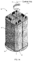
本発明の実施形態に適する収着剤ベッドアセンブリ(すなわち、燃料処理モジュール)の非限定的な例が図1に示されている。収着剤ベッドアセンブリ(すなわち、燃料処理モジュール)80は、脱硫材料などのガス浄化のための材料を各々含む4つの収着剤ベッド82を含むことができる。4つの収着剤ベッドが示されているけれども、アセンブリは例えば2個、3個、または4個より多くの(例えば、5個〜10個)任意の適切な数の収着剤ベッドを含むことができる。種々の実施形態において、収着剤ベッドアセンブリ80は、図を簡略化するために、2個または4個の収着剤ベッドとともに描かれている。収着剤ベッド82を、中心軸85の周りに回転する回転可能な支持パッド84の上に配置することができる。回転可能なパッド84は、他の収着剤ベッド82の動作を妨げることなく各収着剤ベッド82に容易にアクセスして別々に保守点検することを可能にする。
A non-limiting example of a sorbent bed assembly (ie, a fuel processing module) suitable for embodiments of the present invention is shown in FIG. The sorbent bed assembly (ie, fuel processing module) 80 can include four
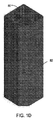
収着剤ベッド82は、面取りされた縁83を有する概して矩形の角柱状物体である。面取りされた縁83は、回転可能なパッド84上で収着剤ベッド82を適宜方向付けするのに役立つ。面取りされた縁83は、さらに、そうでなければ回転可能パッド84を越えて延びて収着剤ベッドアセンブリ(すなわち、燃料処理モジュール)80の回転を妨げることになるであろう収着剤ベッド82の角をなくすことによって、4個の収着剤ベッド82の全てを一緒に回転させるときに、より良好なスペース利用を可能にする。背が高くて細い収着剤ベッド82は、収着剤ベッドアセンブリをキャビネットなどの深くて狭いスペースに置くことを可能にする。
The
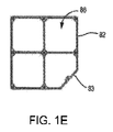
図1B〜1Eを参照すると、収着剤ベッド82の各々は4個の内部チャネル86(例えば、区画チャンバ)を持つことができ、燃料は収着剤ベッド内のチャネル86の各々を流体直列に通過する。従って、4つの収着剤ベッド82の全てが流体直列に接続されたならば、収着剤ベッドアセンブリ80(すなわち、燃料処理モジュール)は本質的に流体直列の16個のチャネル86を有することになる。これに反して、セットとして直列に接続された2つの収着剤ベッド82を2つの収着剤ベッド82の他の1つのセットと並列に接続することができる。この場合、直列の8個のチャネルのセットが、直列の8個のチャネルの他の1つのセットと並列に接続される。とにかく、収着剤ベッド82は低コストのデザインであり、押出方法を用いて製造することができる。チャネル86の比較的に大きな長さ/差し渡し比は、材料効率を高める。チャネル86の形状寸法は、燃料入口流の適度な圧力降下と割合に一様な流れとをもたらす。各収着剤ベッド82の4か所でバルク混合が生じ、エッジ効果とバイパスとを低減させる。
Referring to FIGS. 1B-1E, each of the
チャネル86は、燃料流の中の異なる成分を除去するように最適化された異なる化合物を含むことができる。さらに、流体的に接続される複数のベッド82は、燃料流から異なる成分を除去するように最適化された互いに異なる化合物を含むことができる。
収着剤ベッド82のための全ての入出力(I/O)接続部88は収着剤ベッドアセンブリ(すなわち、燃料処理モジュール)80の同じ側(例えば、頂部側)に設けられる。I/O接続部88は、旋回する密閉接続部である。旋回接続部は、収着剤ベッドアセンブリ80が中心軸85の周りを回転するときに収着剤ベッドアセンブリが動作し続けることを可能にする。
All input / output (I / O)
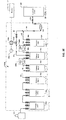
図2は、I/O接続部と直列に接続された4個の硫黄収着剤ベッドの収着剤ベッドアセンブリ(すなわち、燃料処理モジュール)280を示す。4個の収着剤ベッドDES801、DES802、DES803およびDES804は、保守点検要員が容易にバイパスして収着剤ベッドを交換することを可能にするクイックコネクト/ディスコネクト801s〜815sなどのI/O接続部88を有することができる。
FIG. 2 shows a sorbent bed assembly (ie, fuel processing module) 280 of four sulfur sorbent beds connected in series with an I / O connection. The four sorbent beds DES801, DES802, DES803, and DES804 are I / Os such as quick connect / disconnect 801s-815s that allow maintenance personnel to easily bypass and replace the sorbent beds. A
1つの実施形態では、直列に接続された収着剤ベッド82の各々は、飽和レベルの結果として有機硫黄化合物が吸収されずに収着剤ベッド82から逃れるようになるまで有機硫黄化合物などの硫黄を吸収することができる。収着剤ベッドアセンブリ280が通常の動作をしているとき、直列に接続されている初めの3個の収着剤ベッド82は突破を許される。直列の第3の収着剤ベッド82(例えば、DES803)を硫黄化合物が突破することを硫黄検出器が検出すると、第1の収着剤ベッド82(例えば、DES801)はバイパスされて除去される。収着剤ベッドDES801は、接続部803s〜803pを閉じて接続部802sを接続部805pに接続することによってバイパスされ得る。このようにして、燃料入口流は収着剤ベッドDES801をバイパスして入口からまっすぐに接続部802s〜805pを通って第2の収着剤ベッドDES802内に移動する。その後、収着剤ベッドDES801はアセンブリ280から取り外されて未使用のガス浄化材料で再び満たされる。収着剤ベッド82は90度回転され、初めに直列内の2番目だった収着剤ベッド82/DES802が第1の位置に置かれる。同様に、以前は直列内の3番目だった収着剤ベッド82/DES802は第2の位置へ移動され、以前は直列内の最後だった収着剤ベッド82/DES804は第3の位置へ移動される。その後、新しい収着剤ベッド82が第4の位置に置かれる。新しい収着剤ベッドを、その入口を接続部815pに、その出口を接続部815sに、これら2つの接続部がバイパスされている間に、接続することによって、接続することができる。そうすることによって、各収着剤ベッド82は、硫黄が第3の収着剤ベッド82/DES803を突破した後も、硫黄を収集することができる。
In one embodiment, each of the
回転可能なパッド84の上に収着剤ベッド82を配置することにより、回転手順を定数とすることによって混乱を避けることができる。4個の収着剤ベッド82を用いることにより、使用済み収着剤ベッド82を取り外して新しい収着剤ベッド82を据え付ける間、カスケード列中の中央の収着剤ベッド82間の接続は乱されないままであることができる。収着剤ベッド82は回転可能なパッド84上に配置されているので、4個の収着剤ベッド82の全てをモジュールハウジングコンテナの前部の直ぐ近く(例えば、米国のUL規定に適合するように14インチ以内)に配置することができる。I/O接続部88は、収着剤ベッド82が自身の場所を順番に替える間、入口および出口鉛管類が同じ場所に留まることを可能にする。
By placing the
前述した収着剤ベッドアセンブリ(すなわち、燃料処理モジュール)80は概して堅い収着剤ベッド82内に緩いガス浄化材料を含むが、他の1つの典型的な実施形態では、ガス浄化材料はガス透過性のバッグの中に予め装填され得る。そのとき、ガス浄化材料のガス浄化収着剤ベッド82内への詰込みは、バッグを収着剤ベッド構造内への装填を介して簡単化され、これにより材料を定位置につぎ込む必要をなくす。これは、バッグを迅速に取り外すことができるので、取り外しをより容易にする。使用済材料のバッグを収着剤ベッド82から取り外すのに役立つようにハンドル、ロープ、あるいは他のものをバッグに取り付けることができる。ガス浄化アセンブリが前に記載されているが、ガス浄化アセンブリ以外の他の任意の収着剤ベッドアセンブリは回転可能なサポートと回転可能なサポート上に配置された複数の容器とを含むことができ、各容器は収着剤ベッドを含む。
Although the sorbent bed assembly (ie, fuel processing module) 80 described above generally includes a loose gas purification material within the
予備収着剤ベッドと直列に接続された収着剤ベッド
収着剤ベッドを予備収着剤ベッドとして蓄えて置けば、保守点検要員は、硫黄または他の望ましくない成分が燃料電池スタック(すなわち、発電モジュール)に到達する前に収着剤ベッドを交換するための期間を延ばすことができる。収着剤ベッドアセンブリ(すなわち、燃料処理モジュール)280の通常(すなわち、定常状態)動作中、最後の収着剤ベッドDES804は燃料から硫黄(例えば、有機硫黄化合物)または他の内容物を受け取ることがあり、それは収着剤ベッドの寿命を部分的に消尽し得る。従って、収着剤ベッド/DES804を通常(すなわち、定常状態)動作中にオフラインに取り出すことにより、収着剤ベッド/DES804は、収着剤ベッドDES801〜803が消尽された後にオンラインに戻されたならば、硫黄を除去するためにより効率的であり得る。未使用の収着剤ベッド/DES804は、部分的に使用済となった収着剤ベッドより多くの硫黄内容物を除去することができ、ベッドDES801〜803が交換/移動される間に保守点検要員により多くの時間を与え、従って燃料電池スタックを活性低下の可能性から守ることができる。さらに、通常(すなわち、定常状態)動作中、燃料電池システムは、燃料がより少ない(例えば、4個の代わりに3個の)ベッドを通ることによる圧力損失の減少から損害を被り得る。
If the sorbent bed sorbent bed connected in series with the pre-sorbent bed is stored as a pre-sorbent bed, maintenance personnel will have sulfur or other undesirable components contained in the fuel cell stack (ie, The period for replacing the sorbent bed before reaching the power generation module) can be extended. During normal (ie, steady state) operation of the sorbent bed assembly (ie, fuel processing module) 280, the last
図3A〜3Dは、直列に接続されたベッドを有する収着剤ベッドアセンブリ(すなわち、燃料処理モジュール)80の種々の構成を示す。図3Aは、燃料源101および燃料電池スタック(すなわち、発電モジュール)105に流体的に接続された2個の収着剤ベッド82を有する収着剤ベッドアセンブリ380aを示す。燃料源101は、収着剤ベッドアセンブリ380aおよび燃料電池スタックに用いられるのに適した任意の燃料源であり得る。いくつかの例は、保持タンク、加圧タンク、ガスボンベ、または天然ガスなどの広く利用し得る燃料源へのパイプラインを含む。実際の燃料源101は、天然ガス、プロパン、メタン、バイオガス、あるいは燃料電池システムに用いるのに適する他の任意の燃料であり得る。
3A-3D illustrate various configurations of a sorbent bed assembly (i.e., fuel processing module) 80 having beds connected in series. FIG. 3A shows a
収着剤ベッドアセンブリ380a内の1つの収着剤ベッドは主使用ベッド82aであり、他方の収着剤ベッドは予備収着剤ベッド82bであり得る。天然ガスなどの燃料は、燃料源101から、望ましくない成分(例えば、硫黄)を除去する第1の主収着剤ベッド82aに流れることができる。バルブ102aが開いていれば、燃料は、導管91を通って導管94へ流れて燃料電池スタック105(すなわち、発電モジュール)に流入し、これにより接続部88b、導管92、予備収着剤ベッド82b、および導管93をバイパスする。モニタ110は、電圧計、電流計、および/または電力計および燃料電池スタック105ならびに燃料電池スタックの燃料入口に接続されている流量計に電気的に(または無線で)接続されたコンピュータサーバまたは他の任意の計算装置であり得る。モニタ110は燃料電池スタック105の性能を監視することができ、燃料電池スタックの性能が活性低下(例えば、燃料電池アノード電極の硫黄汚染)に起因して劣化しているとモニタ110が判定すれば、モニタはバルブコントローラ102bに信号を送ることができ、これはバイパス導管91内のバルブ102aを作動させて閉じさせる。バルブ102aが閉じると、通常ならばバイパス導管91を介して予備収着剤ベッド82bをバイパスする燃料は接続部88bから導管92を介して、燃料流から硫黄材料を捕らえる予備収着剤ベッド82bを通って移動する。燃料入口流は、その後、収着剤ベッド82bから接続部88cおよび導管93、94を介して燃料電池スタック105のほうへ移動する。収着剤ベッドアセンブリ380aは、各収着剤ベッド82に1つ以上のI/O接続部88を有することができ、使用後の収着剤ベッド82を交換あるいは保守点検することを可能にする。燃料入口導管94内の粒子フィルタ103は、収着剤ベッド材料が燃料電池スタック105に入るのを防ぐために、燃料入口流中に捕らえられたどんな収着剤ベッド材料(例えば、ゼオライト)をも除去する。バルブ104は、粒子フィルタ103(例えば、ゼオライトのビルドアップを除去するため)または収着剤ベッドアセンブリの他の任意の部分を保守点検するために収着剤ベッドアセンブリ380aを燃料電池スタック105から分離するために使用され得る。さらに、バルブ104は、任意の望ましくない成分の濃度が高すぎる場合に燃料電池スタックへの燃料の流れを遮断するためのフェイルセーフとして役立つことができる。図3Aはバルブ104を手動バルブとして示しているけれども、代わりの構成では、それは自動であり得る。
One sorbent bed in
燃料電池スタックの性能は収着剤ベッド消尽または望ましくない成分の検出の指標として使用され得るけれども、これは燃料電池スタック(すなわち、発電モジュール)を不必要なダメージにさらすことを必要とする。従って、検出器を使用すれば、燃料電池スタックの寿命を延ばすことができるとともに収着剤ベッドが消尽されて突破イベントが生じたかどうかを判定するためのより正確でリアルタイムのデータを提供することができる。図3Bは、収着剤ベッドアセンブリ380b内のバイパス導管91内のバルブコントローラ102bに電気的に接続(または無線で接続)され得る検出器106aを含む収着剤ベッドアセンブリ380bを示す。変色検出器、抵抗性検出器、人工鼻、または他の任意の適切な検出器タイプなどの検出器106aは、主収着剤ベッド82aの下流側で、またバルブ102aの上流側で、バイパス導管91内の燃料流の硫黄突破を検出することができる。検出器106aがしきい値レベルの望ましくない成分(例えば、硫黄)を検出すれば、バルブコントローラ102bに対してバルブ102aを閉じるように信号を発することができる。これにより、望ましくない成分が燃料電池スタック105に入るのを防いで燃料を主収着剤ベッド82aから導管92を介して予備収着剤ベッド82bに送ることができる。検出器106aは、主収着剤ベッドが消尽されたことまたは主収着剤ベッド82aが処理できる量よりも多くの硫黄含有物を燃料流が有していることを示すことができ、これにより予備収着剤ベッドを活性化させることができる。この実施形態の利点は、燃料電池スタック105が燃料中の望ましくない成分の指標ではなくて、それらへの燃料電池スタックの被曝を減少させるということである。図3Bの他の構成要素は、図3Aの場合と同じであるので、簡略化するために示していない。
Although fuel cell stack performance can be used as an indicator of sorbent bed exhaustion or detection of undesirable components, this requires subjecting the fuel cell stack (ie, the power generation module) to unnecessary damage. Thus, the use of the detector can extend the life of the fuel cell stack and provide more accurate and real-time data for determining whether the sorbent bed has been exhausted and a breakthrough event has occurred. it can. FIG. 3B shows a
図3Cは、図3Cが主収着剤ベッド82a上/内に位置する追加の検出器106b、106c、および106d、ならびに主収着剤ベッド82aの下流側でバイパス導管91上に位置する検出器106aを有する収着剤ベッドアセンブリ380cを示していることを除いて、図3Aおよび図3Bと同様である。収着剤ベッドアセンブリ380cは4個の検出器106a、106b、106c、および106dを示しているが、収着剤ベッドアセンブリのために任意の数の検出器が使用され得る。例えば、主収着剤ベッド82a上/内に位置する検出器106bなど、唯一の検出器が収着剤ベッドアセンブリ380cに使用され得る。他の1つの例では、主収着剤ベッド82a上の1つの検出器と、主収着剤ベッド82aの下流側のバイパス導管91内の1つの検出器とがあり得る。
FIG. 3C shows
さらなる例において、バイパス導管91内の検出器106aとともに、あるいは検出器106aをともなわずに、主収着剤ベッド82a上/内に2つ以上の検出器があり得る。主収着剤ベッド上/内に位置する1つ以上の検出器は、その1つまたは複数の検出器が特定のしきい値レベルを超える望ましくない成分(例えば、硫黄)を検出したならば、その1つまたは複数の検出器がバルブコントローラ102bに対してバルブ102aを閉じるように信号を発し得るように、バルブコントローラ102bに電気的に接続(または無線で接続)され得る。収着剤ベッドアセンブリ380cが4個の検出器106a、106b、106c、および106dなどの2個以上の検出器を含む実施形態では、各検出器は異なる望ましくない成分を検出することができる。例えば、検出器106aは硫黄突破イベントを判定するのに役立つように硫黄を検出することができ、検出器106bは、収着剤ベッド82aおよび82bおよび/または燃料電池スタック(すなわち、発電モジュール)105に望ましくない影響を及ぼして所与の燃料流量からの発電を減少させ得るシロキサンを検出することができる。この例を続けると、検出器106cおよび106dはそれぞれ酸素および過剰な水(あるいは水分)を検出することができ、それらも、いずれかの望ましくない成分が燃料流を介して燃料電池スタック105に達すれば、燃料電池スタックの性能を低下させ得る。収着剤ベッドアセンブリが4個の検出器106a、106b、106c、および106dなどの2個以上の検出器を含む他の1つの実施形態では、これらの検出器のうちの2つ以上は、同じ望ましくない成分を検出するための冗長検出器であり得る。冗長検出器は、収着剤ベッドアセンブリ380cが2個以上の検出器の検出に基づいてバルブ102aを制御することを可能にする特定の望ましくない成分(例えば、硫黄)の追加の測定を提供することができ、これにより、欠陥のある単一の検出器がバルブコントローラ102bにバルブ102aを閉じるように信号を発したり、あるいは信号を発しなかったりするのを防ぐことができる。例えば、冗長検出器がなければ、単一の検出器の較正の機が既に来ているのに燃料流(または主収着剤ベッド)内の硫黄の検出がなされないという結果になり得る。バルブ102aを閉じるようにバルブコントローラ102bに指令する代わりに、正確で適切に較正された検出器がするであろうように、燃料流内の容認し得る量の硫黄(例えば、しきい値レベルより少ない)を検出し、バルブコントローラ102bに対してバルブ102aを閉じるようには指令しない。従って、燃料は、決して、燃料流内の硫黄の量を減らす予備収着剤ベッド82bへ導管92を通して転換されず、それは、いったん硫黄が燃料入口導管94を通って燃料電池スタックに入れば、燃料電池スタック105の活性を低下させるという結果をもたらす。収着剤ベッドアセンブリ380cが不正確な検出器と正確な冗長検出器とを含む代わりの例では、正確な冗長検出器は、バルブコントローラ102bに対してバルブ102aを閉じるように信号を発して予備収着剤ベッド82bをオンラインにして、燃料電池スタック105が過剰な量(あるいは任意の量)の硫黄を受け取るのを防ぐことができる。
In a further example, there may be more than one detector on / in the
代わりの実施形態では、主収着剤ベッド82aは主収着剤ベッド上/内に位置する少なくとも2個の検出器106bおよび106cを有することができ、各検出器は、同じ望ましくない成分(例えば、硫黄)を、主収着剤ベッド82aの中の異なる位置で、検出する。各検出器106b、106cは、主収着剤ベッド82aの消尽状態を提供するかあるいは消尽状態に貢献して、主収着剤ベッド82aが部分的に消尽されたかあるいは完全に消尽されたかに関する情報を提供することができ、それをデータベースに格納するかあるいはコンピュータスクリーンで表示し得る。例えば、検出器106bを主収着剤ベッドの出口の近くに置くことができ、検出器106cを主収着剤ベッドの中央に置くことができる。検出器106cは主収着剤ベッドが半ば消尽されたことを検出することができ、検出器106bは主収着剤ベッドが完全に消尽されたことおよび予備収着剤ベッドへ切り替えて主収着剤ベッドを交換する時期であることを検出することができる。中間消尽状態情報は、燃料電池システムの運転コストの減少につながるので、収着剤ベッドの消尽のより正確な予測により主収着剤ベッドの不必要な保守点検を減らすとともに交換用収着剤ベッドの在庫を維持する必要を少なくするという結果をもたらし得る。
In an alternative embodiment, the
図1A〜1Eおよび図2に示されているように配置された4個の収着剤ベッド82などの3個以上の収着剤ベッドを使用すれば、図3A、図3B、および図3Cに示されているような2個の収着剤ベッド82より寿命を長くするとともにベッド材料をより完全に利用することができる。4個の収着剤ベッドの利益と1つの予備収着剤ベッド82bとを組み合わせれば、保守点検要員に使用済収着剤ベッドを交換するためのより多くの時間を許すことができるとともに通常(すなわち、定常状態)動作中に燃料電池システム全体においてより小さな圧力損失を提供することができる。図3Dは4個の収着剤ベッドを含む収着剤ベッドアセンブリ380dを示し、ここで3個の収着剤ベッドは主収着剤ベッド82aであり、1つの収着剤ベッドは予備収着剤ベッド82bである。この実施形態は、燃料電池スタック(すなわち、発電モジュール)の検出器106aおよびモニタ110が燃料の流れをバイパス導管91から予備収着剤ベッド82bへ転換する指令をバルブ102aに提供し得ることを示しているけれども、検出器106aまたはモニタ110のうちの1つだけがその制御指令を提供することができる。収着剤ベッドアセンブリ360dにおいて、1つの検出器106aがバイパス導管91内で第3の主収着剤ベッド82aの下流側に置かれている。突破イベントが発生していることを検出器106またはモニタ110が検出すると、バルブ102aは、閉じられて、普段は予備収着剤ベッド82bをバイパスする燃料を予備収着剤ベッド82b内へ向かわせるように信号を発することができ、これにより、初めの3個の主収着剤ベッド82aによって濾過されると思われる任意の望ましくない成分を吸収する。
Using three or more sorbent beds, such as four
いくつかの実施形態では、複数の検出器106aが使用され、それらは、初めは主収着剤ベッド82aのセット全体の寿命予測値を判定するために流れの中に置かれ、種々の動作を適宜実行することができる。特に、検出器106aは、各主収着剤ベッド82aおよび予備収着剤ベッド82bの下流側の導管95、96、92および/または93のいずれかに置かれて各々について突破イベントを検出することができる。
In some embodiments,
いくつかの実施形態では、複数のサブシステムに複数の検出器106aが実装され得る。図3Eは、検出器106aを各々含む2つのサブシステムを用いて動作する例としての収着剤ベッドアセンブリ380eを示す。種々の実施形態において、収着剤ベッドアセンブリ380eは6個の収着剤ベッドを含むことができ、ここで5個の収着剤ベッドは主収着剤ベッド82aであり、1つの収着剤ベッドは予備収着剤ベッド82bである。この実施形態は、燃料電池スタック(すなわち、発電モジュール)の検出器106aおよびモニタ110が燃料の流れをバイパス導管91から予備収着剤ベッド82bへ転換させる指令をバルブ102aに提供し得ることを示しているけれども、検出器106aまたはモニタ110のうちの1つだけが単独で制御指令を提供し得る。1つの実施形態では、収着剤ベッドアセンブリ380eは4番目の主収着剤ベッド82aの後で導管96に位置する検出器106aを含むことができ、これは第1のサブシステム390aにおいて動作することができる。1つの実施形態では、第1のサブシステム390aの検出器106aは、第1の主収着剤ベッドから第4の主収着剤ベッド82aの突破を示すように構成され得る。通常動作において、第1のサブシステム390aは動作可能にされ、第4の主収着剤ベッド82aからの燃料は第5の主収着剤ベッド82aを通るように向けられて第5の主収着剤ベッド82aからバイパス導管91へ向けられ得る。さらに、通常動作中、同じく検出器106aを含み得る第2のサブシステム390bは、流体的および/または電気的に絶縁され得る/動作不能にされ得る(すなわち、図3Fに関して後で論じられる遮断バルブを閉じることによって)。第1の主収着剤ベッドから第4の主収着剤ベッド82aからの突破が検出されたならば、種々の実施形態において、バルブコントローラ102bは、導管91内のバルブ102aを閉じて第5の主収着剤ベッド82aからの燃料を予備主収着剤ベッド82bへ向けるように信号を発せられ得る。さらに、第1の主収着剤ベッドから第4の主収着剤ベッド82aからの突破は第2のサブシステム390bの活性化をトリガすることができ、これは導管92内の第5の主収着剤ベッド82aの下流側の他の1つの検出器106aを含み得る。第2のサブシステム390bの動作は、第1の主収着剤ベッドから第5の主収着剤ベッド82aからの突破の検出を含むことができる。第1の主収着剤ベッドから第5の主収着剤ベッド82aからの突破が検出されると、主収着剤ベッド82aの交換を求める要求を予定するために警報が生成される。
In some embodiments,
図3Fは、検出器106aを各々含む2つのサブシステムを用いて動作する他の1つの例である収着剤ベッドアセンブリ380fを示す。種々の実施形態において、収着剤ベッドアセンブリ380fは6個の収着剤ベッドを含むことができ、ここで5個の収着剤ベッドは主収着剤ベッド82aであり、1つの収着剤ベッドは予備収着剤ベッド82bである。図3Eに関して前に論じた収着剤ベッドアセンブリ380eと同様に、収着剤ベッドアセンブリ380fは第4および第5の主収着剤ベッド82aの後に置かれた検出器を含むことができ、それらはそれぞれ第1および第2のサブシステム390a、390bにおいて動作することができる。収着剤ベッドアセンブリ380fにおいて、第1のサブシム390aは第4の主収着剤ベッド82aの出口とバイパス導管91とにまたがることができる。第1のサブシステム390a内の検出器はスリップストリーム検出器706であり得る。図7に関して後でさらに詳しく論じられるように、スリップストリーム検出器706は1つの導管(例えば、導管96)からの小部分の入力燃料の流れを受け取ることができ、それは大部分の燃料の流れ(例えば、第5の主収着剤ベッド82aに入る)と並行して隣接する導管(例えば、バイパス導管91)に入る出力である。さらに、収着剤ベッドアセンブリ380fに示されているように、燃料の流れを転換するために、入口392a、392bを有する四方バルブ392を配置することができる。収着剤ベッドの構成、流れを予備収着剤ベッド82bへ転換させるバルブ102aの配置、および追加の四方バルブ392の配置により、例えば、第1の収着剤ベッドから第3の収着剤ベッド、第4の収着剤ベッドから第6の収着剤ベッド、第1のサブシステム390a、第2のサブシステム390bを分離しおよび/またはバイパスさせるなどの追加の構成オプションを提供することができる。
FIG. 3F shows another example
例えば、通常動作中、バルブ392の入口392aおよび出口392cは開いていて入口392bおよび出口392dは閉じられ、第3の主収着剤ベッド82aからの導管95内の燃料の流れを第4の主収着剤ベッド82aに流入させることができる。他の1つの構成(図示せず)では、バルブ392の入口392bを開いて入口392aを閉じることによって、四方バルブは、燃料の流れが第1から第3の主収着剤ベッド82aをバイパスして最初に源101から第4の主収着剤ベッド82aに流入することを可能にする。これは、燃料電池スタック105が動作して発電し続けている間に第1から第3のベッドを保守点検したりあるいは交換したりすることを可能にする。他の1つの構成(図示せず)では、出口392cを閉じて出口392dを開くことによって、初めの3個の主収着剤ベッド82aを通して通常の燃料の流れが生じ、導管95内の第3の主収着剤ベッド82aからの出口流は第4および第5の主収着剤ベッド82aおよび予備収着剤ベッド82bをバイパスすることができる。これは、燃料電池スタック105が動作して発電し続けている間に第4から第6のベッドを保守点検したりあるいは交換したりすることを可能にする。例えば、初めの5個のベッドで突破イベントが発生したことを収着剤ベッドアセンブリ380f内のアラームおよび/または検出器が示したならば、バルブ102aを閉じ、これにより燃料の流れに予備ベッド82bを通過させることができる。種々の実施形態において、第1のサブシステム390a内の検出器706および第2のサブシステム390b内の検出器106aは、出入口遮断バルブ11を伴って構成され得る。このようなバルブ11は、種々の動作モードの間に検出器706、106aを分離/動作不能にするために使用され得る。例えば、通常動作中、関連するバルブ11を閉じることによって第2のサブシステム390bの検出器106aを分離し/動作不能にすることができ、予備動作中に(すなわち、突破イベントが第1のサブシステム390aによって検出され、バルブ102aが閉じられた後で)検出器706を、これに関連する遮断バルブ11を閉じることによって分離/動作不能にすることができる。
For example, during normal operation, the
いくつかの実施形態の収着剤ベッドアセンブリは種々のセンサインジケータを含むことができる。例えば、センサが電力を受け取って適切に通信しているかをチェックするために「ウォッチドッグ」アラームを含めることができる。他の1つの例であるアラームは、1つ以上のセンサの中の感知材料のための交換アラームであることができる。例えば、1つ以上のセンサの材料が使用済みとなって最早機能していないかを識別するために感知材料の色をしきい値と対照してチェックすることができる。いくつかの実施形態では、センサが使用済み感知材料を含んでいると識別されたとき、制御シグナリングは、該当する1つまたは複数の望ましくない成分の存在を仮定するフェイルセーフ下で動作するように構成され得る。例えば、図3Eに関して前に論じた収着剤ベッドアセンブリ380eにおいて、第1のサブシステム390a内の検出器106aが使用済み感知材料を有すると識別されたならば、全ての検出器106aについて感知材料の交換が必要であることを示す交換アラームをトリガすることができる。さらに、使用済み感知材料がそのように識別された後、前に論じたように少なくとも1つの検出器106aを用いて第1〜第5の主収着剤ベッドを通る燃料の流れを監視するために第2のサブシステム390bを活性化させることができる。第2のサブシステム390b内の検出器106aが使用済み感知材料を有すると識別されたならば、全ての検出器106aについて感知材料の交換が必要であることを示す交換アラームがトリガされ得る。使用済み感知材料がそのように識別された後、前に論じたように予備収着剤ベッド82bの動作が活性化され得る。存在し得る追加のアラームは、1つ以上の検出器106a内の感知材料について、前もってセットされた最低および/または最高寿命予測値に達しているときを示すものを含む。そのような寿命予測値は、使用される材料、感知される望ましくない成分のタイプなどに基づく見積もりとして構成される、前もってセットされる見積もりであり得る。
The sorbent bed assembly of some embodiments can include various sensor indicators. For example, a “watchdog” alarm can be included to check if the sensor is receiving power and communicating properly. Another example alarm can be a replacement alarm for a sensing material in one or more sensors. For example, the color of the sensing material can be checked against a threshold value to identify if one or more sensor materials are used and no longer functioning. In some embodiments, when the sensor is identified as containing spent sensing material, the control signaling is operated under fail-safe that assumes the presence of one or more applicable undesirable components. Can be configured. For example, in the
種々の実施形態において、検出器106aは、安定性を保証するとともに誤ってアラームを発生させることを避けるために、使用前に感度試験を受けることができる。例えば、収着剤ベッドアセンブリに用いられる検出器106aに対する多数の因子の効果を同時に測定するために一定のスクリーニングテストを実行することができる。
In various embodiments,
いくつかの実施形態では、収着剤ベッドアセンブリのためのシステムは、瞬時データおよび/または寿命統計を監視し受け取ることによって時間経過中のその動作を改善するために動的学習を実行することができる。瞬時データは、各収着剤ベッドにおける流量および圧力推定値、ならびに全ての収着剤ベッドにおける累積ガス流量を含み得るけれども、これらに限定はされない。寿命統計は、各収着剤ベッドについての動作時間数(すなわち、ベッドの燃料の流れがゼロより大きい時間数)、全ての収着剤ベッドにおける累積ガス流量、および各収着剤ベッドの最後の交換日を含み得るけれども、これらに限定はされない。これらの動的学習メトリクスは、収着剤ベッド82および/または検出器106に関係し得る。さらに、種々の実施形態は、収着剤ベッド82のためのメトリクスを検出器106のためのメトリクスと比較することに基づく学習メトリクスを含み得る。例えば、収着剤ベッド82を通る総燃料流量を、検出器106を通る総燃料流量と比較することができる。
In some embodiments, a system for a sorbent bed assembly may perform dynamic learning to improve its operation over time by monitoring and receiving instantaneous data and / or lifetime statistics. it can. Instantaneous data may include, but is not limited to, flow and pressure estimates in each sorbent bed, and cumulative gas flow in all sorbent beds. Lifetime statistics include the number of operating hours for each sorbent bed (ie, the number of hours the bed fuel flow is greater than zero), the cumulative gas flow in all sorbent beds, and the last of each sorbent bed. The date of exchange may be included, but is not limited to these. These dynamic learning metrics can relate to the
予備収着剤ベッドと並列に接続された収着剤ベッド
図4A〜4Dは、並列に接続された少なくとも2つの収着剤ベッドを有する収着剤ベッドアセンブリ(すなわち、燃料処理モジュール)の他の1つの実施形態を示す。図4Aは、流体的に並列に接続された1つの主収着剤ベッド82aおよび1つの予備収着剤ベッド82bを有する収着剤ベッドアセンブリ480aを示す。通常(すなわち、定常状態)動作中、主燃料入口導管134内のバルブ124aは開いたままであり、予備燃料入口導管132内のバルブ122aは閉じたままであって、燃料源101からの燃料を導管134および主収着剤ベッド82aだけを通して導管133および94を介して燃料電池スタック(すなわち、発電モジュール)内へ移動させることができる。燃料電池スタック105の性能の低下を検出するモニタ110によって突破イベントが検出されると、モニタ110は、バルブコントローラ124bに信号を送ってバルブ124aを閉じ、同時にバルブコントローラ122bに信号を送ってバルブ122aを開くことができる。これにより、全ての燃料は導管132を通って予備収着剤ベッド82bに流入し、ベッド82bから導管135および94を介して燃料電池スタック105に流入させられる。これにより、燃料電池システムは、主収着剤ベッド82aが保守点検されている間動作し続けることができる。主収着剤ベッド82aへの燃料の流れを遮断することにより、燃料電池システムから実際上切り離され、容易に保守点検され得る。モニタ110が燃料電池スタック105から別の効率低下を検出し、消尽された主収着剤ベッド82aが交換されているならば、モニタ110は、燃料が交換済みの主収着剤ベッド82aを通って流れることができて予備収着剤ベッド82bが保守点検され得るように、信号を発してバルブ124aを開きバルブ122aを閉じることができる。
Sorbent Beds Connected in Parallel with Pre-sorbent Beds FIGS. 4A-4D show other sorbent bed assemblies (ie, fuel processing modules) having at least two sorbent beds connected in parallel. One embodiment is shown. FIG. 4A shows a
代わりの1つの実施形態では、バルブ122aおよび124aは流量制御バルブであって、通常(すなわち、定常状態)動作中、両方のバルブが開かれている。バルブ124aは完全に開かれて燃料の大部分(60〜95%など、50%より多く)が導管134および主収着剤ベッド82aを通って流れることを可能にし、バルブ122aは部分的に開かれて燃料の小部分(5〜40%など、50%未満)が導管132および予備収着剤ベッド82bを通って流れることを可能にする。燃料電池スタック(すなわち、発電モジュール)105において性能の低下が検出されると、モニタ110は、バルブ124aを閉じるようにコントローラ124bに指令するとともにバルブ122aを全開するようにコントローラ122bに指令することができる。これにより、燃料の全てが、導管135および94を介して燃料電池スタック105に入る前に導管132および予備収着剤ベッド82bを通過させられる。消尽された主収着剤ベッド82aを通って流れる燃料はないので、これを交換することができる。消尽済み主収着剤ベッド82aが交換されると、バルブ124aおよび122aは、他の1つの突破イベントが発生するまで、予備収着剤ベッドとして作用する交換済み主収着剤ベッド82aを通って燃料の小部分が流れ、元の予備収着剤ベッド82bが主収着剤ベッドとして作用し得るように、調整され得る。この実施形態のアセンブリ480aは、収着剤ベッド82a、82bの完全利用と燃料電池システムの持続的使用を可能にし、これにより、収着剤ベッドの早めの交換を最小にするとともに燃料電池スタックのエネルギー生産を増大させることによって運転コストを減らすことができる。
In an alternative embodiment,
図4Bは、他の1つの実施形態のシステム480bを示す。このシステムでは、検出器106aは、他の1つの実施形態のシステム480bのバルブコントローラ122b、124bに電気的に接続(あるいは無線で接続)され得る。検出器106aを、燃料入口導管94に置くことができ、燃料電池スタック(すなわち、発電モジュール)の入口流中の望ましくない成分(例えば、硫黄)の存在を検出し分析することができる。検出器106aは、しきい値レベルの望ましくない成分を検出すると、バルブコントローラ124bに対してバルブ124aを閉じるように信号を発することができる。同時に、検出器106aは、全ての燃料が収着剤ベッド82bを通って流れるようにバルブコントローラ122bに信号を送ってバルブ122aを開かせることができる。収着剤ベッドアセンブリ480bの480aに勝る利点は、燃料電池スタック105が燃料中の望ましくない成分のインジケータではなくて、燃料電池スタックの望ましくない成分に対する被曝を少なくすることである。システム380bと同様に、図4Bの他の構成要素は、図4Aの場合と同じであるので、簡略化するために示していない。
FIG. 4B illustrates another
主収着剤ベッド82aおよび予備主収着剤ベッド82bの下流側の導管94上に配置された検出器106aと同様に、追加の検出器106b、106c、および106dが主収着剤ベッド82a上/内に配置され、検出器106e、106f、および106gが予備収着剤ベッド82b上/内に配置されている収着剤ベッドアセンブリ480cを図4Cが示していることを除いて、図4Cは図4Aおよび図4Bと同様である。収着剤ベッドアセンブリ480cは7個の検出器106a〜106gを示しているけれども、収着剤ベッドアセンブリのために任意の数の検出器が使用され得る。例えば、主収着剤ベッド82a上に配置された検出器106bおよび予備収着剤ベッド82b上に配置された検出器106eなど、検出器が2個だけ収着剤ベッドアセンブリ480cにおいて使用され得る。他の1つの例では、収着剤ベッドアセンブリは、各収着剤ベッド82a、82b上の唯一の検出器と、収着剤ベッド82a、82bの下流側の導管94内の1つの検出器とを含むことができる。
Similar to the
さらなる例において、収着剤ベッドアセンブリは、導管94内の検出器106aをともなうあるいはともなわずに、各収着剤ベッド82a、82b上/内の2つ以上の検出器を含むことができる。検出器106aと同様に、収着剤ベッド82a、82b上/内に配置された1つ以上の検出器は、その1つまたは複数の検出器が特定のしきい値レベルを超える望ましくない成分(例えば、硫黄)を検出したならば、1つまたは複数の検出器がバルブコントローラ124b、122bに対してそれぞれのバルブ124a、122aを閉じるように信号を発し得るように、バルブコントローラ124b、122bに電気的に接続(または無線で接続)され得る。例えば、バルブ122aが閉じていてバルブ124aが開いている定常状態のシステムにおいて、燃料源101からの燃料の全ては、導管134を通って主収着剤ベッド82aへ流れ、導管133、導管94、フィルタ103、バルブ104、および燃料電池スタック(すなわち、発電モジュール)105に流入する。
In a further example, the sorbent bed assembly can include two or more detectors on / in each
検出器106b〜106dのいずれかが特定のしきい値レベルより多くの望ましくない成分(例えば、硫黄)を検出したならば、検出器106cなどの検出器は、バルブコントローラ124bに対してバルブ124aを閉じるように指令するとともにバルブコントローラ122bに対してバルブ122aを開くように指令することができる。この変化の結果として、燃料は、燃料源101から予備収着剤ベッド82bを通って移動する前に導管132に流入する。同様に、望ましくない成分を検出したことに応答してバルブ124aを完全に閉じる代わりに、検出器は、燃料の大部分が予備収着剤ベッド82bを通って流れ燃料の小部分が依然として主収着剤ベッドを通って流れるように、バルブコントローラ124bに対してバルブ124aを部分的に閉じるように指令するとともにバルブコントローラ122bに対してバルブ122aを部分的(または完全)に開くように指令することができる。他の1つの例では、バルブ122aが開いていてバルブ124aが閉じている定常状態システムにおいて、燃料源101からの燃料の全ては、導管132を通って予備収着剤ベッド82bへ流れ、導管135、導管94、フィルタ103、バルブ104、および燃料電池スタック105に流入する。いずれかの検出器106e〜106gが特定のしきい値レベルを超える望ましくない成分(例えば、硫黄)を検出すると、検出器106fなどの検出器は、バルブコントローラ122bに対してバルブ122aを閉じるように指令するとともにバルブコントローラ124bに対してバルブ124aを開くように指令することができる。この変化の結果として、燃料は、燃料源101から、主収着剤ベッド82aを通って移動する前に導管134に流入する。同様に、望ましくない成分を検出したことに応答してバルブ122aを完全に閉じる代わりに、検出器は、燃料の大部分が予備収着剤ベッド82bを通って流れ、燃料の小部分が依然として主収着剤ベッドを通って流れるように、バルブコントローラ122bに対してバルブ122aを部分的に閉じるように指令するとともにバルブコントローラ124bに対してバルブ124aを部分的に開く(または完全に開く)ように指令することができる。
If any of the
収着剤ベッドアセンブリ380cと同様に、収着剤ベッドアセンブリ480cの種々の実施形態は、7個の検出器106a〜106gなどの2個以上の検出器を含むことができ、異なる望ましくない成分(例えば、水、酸素、シロキサン、硫黄など)のための検出器、同じ望ましくない成分を検出するための冗長検出器、および/または収着剤ベッドの中間消尽状態情報を確立するための検出器をも含むことができる。異なる望ましくない成分の検出器を含む収着剤ベッドアセンブリ480cの利点は、特定の望ましくない汚染物質が許容可能なしきい値レベルより多いことに応答してバルブを閉じたり、および/または開いたりすることによって、システムが複数のタイプの汚染物質に順応することを可能にすることである。望ましくない成分の冗長検出器を含む収着剤ベッドアセンブリ480cの利点は、冗長ペアのうちの1つの検出器が適切に動作していない(例えば、バルブが不正確な検出を有する、電力の欠如、ダメージを受けた検出器)ときにも、適切に働いている検出器からシステムが指令を受け入れることを可能にすることである。中間収着剤ベッド消尽検出器を含む収着剤ベッドアセンブリ480cの利点は、収着剤ベッドが消尽されるときを正確に概算できることによる総運転コストの低減を可能にすることである。正確な収着剤ベッド消尽概算は、収着剤ベッドの不必要な保守点検(例えば、収着剤ベッドをあまりに早くあるいはあまりに遅く交換する)を減らすとともに交換用主収着剤ベッドの在庫を維持する必要を減らすことにつながる。
Similar to
収着剤ベッド82a、82b内の中ほどで望ましくない成分を測定する1つの検出器を持つことによって確立される中間消尽状態情報は低運転コストである。なぜならば、主収着剤ベッドが消尽される時間をより正確に予測できるので、収着剤ベッドの不必要な保守点検を減らし、交換用主収着剤ベッドの在庫を維持する必要を減らせるからである。
The intermediate exhaustion status information established by having one detector that measures undesirable components in the middle of the
前に論じたように、4個の収着剤ベッド82などの3個以上の収着剤ベッドを用いれば、図4A、図4B、および図4Cに示されている2つの収着剤ベッドよりも寿命をより長くし、ベッド材料をより完全に利用することができる。予備収着剤ベッドの使用を4個の収着剤ベッドと組み合わせれば、そのような燃料電池システムを保守点検するときに有効にコストを回避することができる。図4Dは4個の収着剤ベッド82を含む収着剤ベッドアセンブリ480dを示し、ここで2つの主収着剤ベッド82aは導管136により流体的に直列に接続され、2つの予備収着剤ベッド82bは導管137により流体的に直列に接続されている。2つの主収着剤ベッド82aは2つの予備収着剤ベッド82bと流体的に並列に接続されている。3個以上の主収着剤ベッド82aおよび/または3個以上の予備収着剤ベッド82bを使用することができる。通常(すなわち、定常状態)動作中、バルブ124aを開くことができ、バルブ122aは閉じられたままで、燃料源101からの燃料を、主収着剤ベッド82aだけを通って燃料電池スタック(すなわち、発電モジュール)105に流入させる。検出器106aによって突破イベントが検出されると、検出器106aは、コントローラ124bに対してバルブ124aを閉じるように信号を発するとともにコントローラ122bに対してバルブ122aを開くように信号を発することができる。あるいは、モニタ110は、燃料電池スタック105の性能低下を検出してコントローラ124bに対してバルブ124aを閉じるように信号を発し、コントローラ122bに対してバルブ122aを開くように信号を発することができる。これにより、燃料の流れの全てが予備収着剤ベッド82bを通して向けられ、主収着剤ベッド82aは燃料電池システムから分離され、燃料電池スタックの動作を妨げずにそれらを交換することが可能となる。
As discussed above, using more than two sorbent beds, such as four
代わりの1つの実施形態では、通常(すなわち、定常状態)動作中、バルブ122aは部分的に開かれ得る。バルブ124aを全開して(または部分的に開いて)燃料の大部分が主収着剤ベッド82aを通って流れることを可能にし、バルブ122aを部分的に開いて燃料の小部分が予備収着剤ベッド82bを通って流れることを可能にする。望ましくない成分が主収着剤ベッド82aを突破していることを検出すると、検出器106a(またはモニタ110)はコントローラ124bに対してバルブ124aを完全に閉じるように指令するとともにコントローラ122bに対してバルブ122aを完全に開くように指令することができ、これにより、全燃料を、燃料電池スタック(すなわち、発電モジュール)105に入る前に予備収着剤ベッド82bを通過させる。消尽された主収着剤ベッド82aを通って移動する燃料はないので、これらを交換することができる。交換が終われば、他の突破イベントまでの間、バルブ124aおよび122aは、燃料の小部分が予備収着剤ベッドとして作用する新しい主収着剤ベッド82aを通って流れ、元の予備収着剤ベッド82bが主収着剤ベッドとして作用することができるように、調整され得る。これにより、収着剤ベッド材料を十分に利用できるとともに燃料電池システムを安全に使用し続けることができる。
In an alternative embodiment,
図4Dは、燃料電池スタック(すなわち、発電モジュール)の検出器106aおよびモニタ110がバルブ122aおよび124aに対して指令を提供して流れを予備収着剤ベッド82bへ転換させ得ることを示しているけれども、検出器106aまたはモニタが単独で制御指令を提供することができる。検出器106aを用いる場合、それを予備収着剤ベッド82bおよび主収着剤ベッド82aの接続点の下流側(すなわち、後)で導管94に配置することができる。
FIG. 4D shows that the fuel cell stack (ie, power generation module)
上流側の予備収着剤ベッド
図5は、発電モジュールおよび燃料処理モジュールからモジュラー燃料電池キャビネットの外側に位置する上流側予備収着剤ベッド520を利用する実施形態の燃料電池システム500を示す。上流側予備収着剤ベッド520は、燃料の硫黄含有量が極端に多ければ、燃料源101から供給される燃料から余分の硫黄(硫黄化合物を含む)を除去するために使用され得る。燃料は、燃料源101から、前述したアセンブリ280、380a、380b、380c、380d、480a、480b、480c、または480dなどの収着剤ベッドアセンブリ(すなわち、燃料処理モジュール)に入る前に、天然ガスなどの燃料中のほとんど全ての硫黄を除去する上流側予備収着剤ベッド520を通って流れることができる。発電所での脱臭済み天然ガス(例えば、脱硫済み天然ガス)の輸送に関する規則に従うために、燃料は定期的に上流側予備収着剤ベッド520をバイパスすることができる。例えば、10分ごとに、バイパス導管501内のバイパスバルブ502aは30秒間開いて燃料が導管501を介して上流側予備収着剤ベッド520をバイパスすることを可能にする。従って、時間のほんの一部分、匂いのある天然ガスが燃料電池システム内に供給される。例えば、硫黄の匂いを感じることによってシステムにおいて天然ガスの漏れがあるかどうかを近くの作業員が判定できるように、匂いのある燃料は時間の0.1〜10%の間、予備収着剤ベッド520をバイパスする。従って、嗅覚による漏れ検出を可能にするために、上流側収着剤ベッド520は硫黄の全部ではなくて大部分を除去する。
Upstream Pre-Sorbent Bed FIG. 5 illustrates an embodiment
1つの代替の実施形態では、燃料電池システム500は、上流側予備収着剤ベッド520がバイパスされる通常動作状態(すなわち、定常状態)を持つことができる。バルブ502aは全開され、流体力学は、燃料を、上流側予備収着剤ベッド520を通らせるのではなくて導管501を介して予備収着剤ベッド520の周りを流れさせる。あるいは、導管532内の追加のバルブ(図示せず)は、燃料が予備収着剤ベッド520に流入するのを妨げることができる。それでも、導管501内の上流側検出器506は、未精製燃料流中の硫黄の量を測定することができる。硫黄の量がしきい値レベルに達して、源101からの燃料が所望の望ましくない成分(例えば、硫黄)含有量より多い望ましくない成分を有することを示すならば、検出器506はコントローラ502bに対してバルブ502aを閉じるように信号を発して燃料に上流側予備収着剤ベッド520を通らせることができる。他の1つの代替の実施形態は、前述した収着剤ベッドアセンブリ(すなわち、燃料処理モジュール)280、380a、380b、380c、380d、480a、480b、480c、または480d内のモニタ110または検出器106による突破イベントの検出に基づいて強制的に燃料に上流側収着剤ベッド520を通らせることを含む。どちらの突破検出方法も、燃料が収着剤ベッドアセンブリ280、380a、380b、380c、380d、480a、480b、480c、または480dを通って流れる前に燃料を別の上流側予備収着剤ベッド520を通らせるべくバルブ502aを閉じるようにコントローラ502bに対して信号を発することができる。
In one alternative embodiment, the
さらなる代案として、収着剤ベッドアセンブリ(すなわち、燃料処理モジュール)280、380a、380b、380c、380d、480a、480b、480c、または480dとは異なるタイプの望ましくない成分を除去するために上流側予備収着剤ベッド520を使用することができる。例えば、収着剤ベッドアセンブリ280、380a、380b、380c、380d、480a、480b、480c、または480dは硫黄を除去することができ、上流側収着剤ベッド520は水(または水分)などの他の望ましくない成分を除去することができる。上流側検出器506は、燃料源101からの燃料入口流中の水含有量を測定することができる。通常(すなわち、定常状態)動作中、燃料源101からの燃料は、開いているバルブ502aおよび導管501を通って上流側予備収着剤ベッド520をバイパスすることができる。燃料源101からの燃料流がしきい値レベルの水を含んでいるならば、導管501内でバルブ502aの前に置かれている検出器506は、バルブコントローラ502bに対してバルブ502aを閉じるように信号を発して燃料を逸らして上流側予備収着剤ベッド520を通らせて水を除去することができる。その後、水分含有量がしきい値より低く測定されたならば、上流側検出器506は、信号を発してバルブ502aを開かせることができる。あるいは、上流側予備収着剤ベッド520を、しきい値レベルの水が検出されたときだけではなくて、水を除去するために常時使用することができる。
As a further alternative, a sorbent bed assembly (ie, fuel processing module) 280, 380a, 380b, 380c, 380d, 480a, 480b, 480c, or upstream reserve to remove unwanted components of a different type from 480d. A
燃料源切り替え
図6は、複数の燃料源(例えば、2つ以上の源)101a、101bを有する燃料電池システム600を示す。図に示されている実施形態では、各燃料源101a、101bは、それぞれ関連する検出器672、671、コントローラ682b、681b、およびバルブ682a、681aを有することができる。1つの特定の実施形態では、通常(すなわち、定常状態)動作は、バルブ682a、681aを開くことによって両方の燃料源101a、101bを使用することを含むことができる。しかし、1つの検出器672または671が望ましくない成分を検出すると、検出器672または671は、大量の望ましくない成分を含有する燃料源と関連するそれぞれのバルブ682a、681aを閉じるようにそれぞれのバルブコントローラ682b、681bに対して信号を発する。例えば、通常(すなわち、定常状態)中、両方の燃料源101aおよび101bからの燃料は、それぞれの導管631、632、共通入口導管594、前述した収着剤ベッドアセンブリ(すなわち、燃料処理モジュール)280、380a、380b、380c、380d、480a、480b、480c、または480dを通り、燃料入口導管94を通って燃料電池スタック(すなわち、発電モジュール)105へ流れることができる。導管632内の検出器672は、燃料源101bからの望ましくない成分の含有量がしきい値レベルより多いことを検出したならば、燃料源101bからの燃料が燃料電池スタック105に入るのを止めるためにバルブ682aを閉じるようにコントローラ682bに対して信号を発することができる。従って、燃料源101aからの燃料だけが燃料電池システム600において使用され得る。他の1つの実施形態では、燃料電池スタック105の性能がしきい値レベルより低下すると、モニタ110は、大量の望ましくない成分を含有すると分かった(例えば、検出器672から検出された)燃料源101aと関連するバルブ682aを閉じるように同様の指令を送ることができる。他の1つのフェイルセーフとして、燃料電池システム600は自動バルブ636aを含むことができ、これにより、望ましくない成分の突破イベントが検出されたときに燃料電池スタック105に入る燃料の流れをオン/オフするか、あるいは減少させることができる。
Fuel Source Switching FIG. 6 shows a
1つの代替の実施形態では、通常(すなわち、定常状態)動作は、しきい値レベルより多い望ましくない成分が検出されるまでは一度に唯一の燃料源を用い、そのときに他の1つの燃料源に切り替えることを含むことができる。使用されている燃料源に関連する検出器が、燃料流がしきい値レベルより多い量の望ましくない成分を含むことを検出したならば、検出器はその使用中の燃料源と関連するバルブを閉じるように信号を発すると同時に、使用されていない燃料源と関連するバルブを開くように信号を発する。例えば、通常(すなわち、定常状態)動作中、収着剤ベッドアセンブリ(すなわち、燃料処理モジュール)280、380a、380b、380c、380d、480a、480b、480c、または480dおよび燃料電池スタック(すなわち、発電モジュール)105とともに燃料源101aからの燃料だけを使用することができる。検出器671は、燃料源101aからの燃料中の特定の望ましくない成分と、望ましくない成分の濃度とを検出することができる。収着剤ベッドアセンブリ280、380a、380b、380c、380d、480a、480b、480c、または480dから検出器106a〜106gが突破イベントを検出するか、あるいはモニタ110が燃料源101aと関連する望ましくない成分に基づいて燃料電池スタック105が性能低下を被っていることを検出すれば、バルブ681aを閉じるように信号が発せられ、バルブ682aは開くように信号が発せられ得る。従って、燃料電池システム600および対応する収着剤ベッドアセンブリ280、380a、380b、380c、380d、480a、480b、480c、または480dおよび燃料電池スタック105は燃料源101bからの燃料を受け取るだけであり、これにより燃料源を切り替える。
In one alternative embodiment, normal (ie, steady state) operation uses a single fuel source at a time until an undesirable component above a threshold level is detected, at which time one other fuel is used. Switching to the source can be included. If the detector associated with the fuel source being used detects that the fuel flow contains an amount of undesirable components greater than a threshold level, the detector activates a valve associated with the fuel source in use. A signal is issued to close and at the same time to open a valve associated with an unused fuel source. For example, during normal (ie, steady state) operation, the sorbent bed assembly (ie, fuel processing module) 280, 380a, 380b, 380c, 380d, 480a, 480b, 480c, or 480d and the fuel cell stack (ie, power generation) Only the fuel from the
1つの代替の実施形態では、検出器672、671、バルブ682a、681aおよびコントローラ682b、681b、636bのいずれかまたは全部が収着剤ベッドアセンブリ280、380a、380b、380c、380d、480a、480b、480c、または480dの一部であり得る。収着剤ベッドアセンブリ280、380a、380b、380c、380d、480a、480b、480c、または480dは、システム600のニーズに基づいて特定の燃料源を選択するか、あるいは燃料電池スタック(すなわち、発電モジュール)105への燃料の流れを変更することができる。
In one alternative embodiment, any or all of
スリップストリーム検出器
図7は、導管712から燃料を受け入れ、スリップストリーム導管716を通してそれを主収着剤ベッド82aへ戻す検出器706を示す。図3B〜3Fおよび図4B〜4Dの各検出器は、それらに隣接する導管または収着剤ベッドとT継手風に接続することを示しているけれども、これらの実施形態に関して図に示され記述された検出器は、図7に示されているものと同様のスリップストリームを利用することができる。スリップストリーム検出器706は、隣接する導管内の大部分の燃料の流れと並行する小部分の燃料の流れを受け取る。1つの実施形態では、燃料の小部分が導管712を通ってスリップストリーム検出器706および主収着剤ベッド82aに流入することができる。同時に、燃料の大部分は、スリップストリーム検出器706を通って移動することなく、導管714を通って主収着剤ベッドに流入する。図7に示されているように、スリップストリーム検出器706は、収着剤ベッドの上流側で望ましくない成分を検出する。スリップストリーム検出器は、主収着剤ベッドが除去するのと同じ望ましくない成分(例えば、硫黄)を検出することができ、図6に関して前に記載したように燃料源101aおよび/または101bを切り替えるために使用することができる。あるいは、スリップストリーム検出器706は、主収着剤ベッドが除去するものとは異なる望ましくない成分を検出することができる。例えば、主収着剤ベッドが硫黄を除去するならば、主収着剤ベッドの上流側に位置するスリップストリーム検出器706は、シロキサンなどの他の望ましくない成分を検出する。
Slipstream Detector FIG. 7 shows a
他の1つの実施形態では、スリップストリーム検出器706は他の1つの収着剤ベッド(図示せず)の下流側にあることができる。例えば、スリップストリーム検出器706を図3Dの導管95上に配置することができ、これは第1の主収着剤ベッド82aの下流側で第2の主収着剤ベッド82aの上流側に位置する。この例では、スリップストリーム検出器706は、第1および第2の主収着剤ベッド82aが除去するのと同じ望ましくない成分(例えば、硫黄)を検出し、第1の主収着剤ベッドの下流側に存在する望ましくない成分の貴重な検出を提供することができる。第1の主収着剤ベッドの下流側での検出は、第1の主収着剤ベッドの突破イベントを示し、それを交換する必要があることを示すことができる。さらに、初めのほうの収着剤ベッドでの突破の検出は、予備収着剤ベッド82bを活性化させる信号を送ることができる。
In another embodiment, the
他の1つの例では、第1の主収着剤ベッド82aの下流側で第2の主収着剤ベッド82aの上流側にある、図4Dの導管136にスリップストリーム検出器706を配置することができる。さらに、第1および第2の予備収着剤ベッド82bの間にある、図4Dの導管137にスリップストリーム検出器706を配置することができる。導管136または導管137において、スリップストリーム検出器706は、第1および第2の収着剤ベッドが除去するのと同じ望ましくない成分(例えば、硫黄)を検出することができ、第1の収着剤ベッドの下流側に存在する望ましくない含有物の貴重な検出を提供することができる。第1の収着剤ベッド82a、82bの下流側での検出は、第1の収着剤ベッド82a、82bの突破イベントを示し、それを交換する必要があることを示すことができる。
In another example, the
このスリップストリーム検出器を、主流路内の収着剤ベッドまたはバルブなどのフィーチャと十字に交わって、フローフィーチャにより生じる圧力降下がスリップストリーム検出器を通る流れを駆動することとなるように、接続することができる。 Connect this slipstream detector in a cross with features such as sorbent beds or valves in the main flow path so that the pressure drop caused by the flow feature will drive the flow through the slipstream detector can do.
このスリップストリーム検出器は、検出器への流れを遮断するために導管712および/または導管716に配置された1つまたは複数のバルブを使用することができる。これらのバルブは、システム動作中に変色カートリッジまたはセンサが機能しなくなった場合にセンサの交換を容易にし得る。さらに、センサの流れ配管工事のときにバルブを使用することは、変色カートリッジの有限の寿命を維持することを可能にする。一例は、システム380cなどの実施形態にある。センサ106の入口および/または出口でのバルブの使用は、センサ106bが望ましくない成分の突破を示すなど、何らかの判定基準が満たされるまで、流路内にさらに存在するセンサ106dを閉じておくことを可能にする。
The slipstream detector can use one or more valves located in
検出器およびデータベースマップ
図8Aは、検出された望ましくない成分に基づいてシステムパラメータ(例えば、バルブを開く/閉じること、燃料電池スタックを運転停止することなど)を自動的に変更する検出システムを示す。燃料電池システムの燃料の流れの中の種々の位置で望ましくない成分を検出するために種々の検出器106a〜106g、506、672、671、および/または706を使用することができる。検出器の正確な位置にかかわらず、各検出器は、酸素、水、シロキサン、および硫黄などの望ましくない成分を検出するのに適する任意のタイプであってよい。
Detector and Database Map FIG. 8A illustrates a detection system that automatically changes system parameters (eg, opening / closing valves, shutting down a fuel cell stack, etc.) based on detected undesirable components. .
1つの特定の実施形態では、1つまたは複数の検出器は1つ以上の変色検出器であり得る。各変色検出器は、図8Aに示されている変色パッド850などの変色領域を含み、こ特定のタイプの望ましくない成分にさらされた後に変色する。例えば、白色検出器パッドを有する変色検出器は、硫黄にさらされると黄色くなる。変色検出器106a〜106g、506、672、671、および/または706は、感色光検出器852などの光学コンポーネント、および任意にパッドを照明する光源854を有することができる。光学コンポーネントは、色の変化を記録し、その情報を変色データベース811に送る。変色データベース811は、検出器106a〜106g、506、672、671、および/または706から入ってくる変色データを収集して変色マップを作成し/アップデートし、測定される燃料流中の特定の望ましくない成分の強度を判定する。変色検出器から受け取られた色の変化に基づいて、燃料流中の特定の望ましくない成分の量を予測するために変色の量または強度を較正することができる。変色検出器106a〜106g、506、672、671、および/または706からの実時間データをシステムコントローラ890に送ることができ、収着剤ベッドアセンブリ(すなわち、燃料処理モジュール)内のバルブ、燃料電池スタック(すなわち、発電モジュール)と関連するバルブ、燃料選択のためのバルブ、あるいは燃料電池システムの部分を止めるなどの他の任意の動作制御などのシステムパラメータを変更することができる。突破イベント(例えば、最後の主収着剤ベッドの後で硫黄)を検出したら予備収着剤ベッドを使用するなどのシステムパラメータの変更のうちのいくつかについて、図1〜7に関して前に記述した。
In one particular embodiment, the one or more detectors may be one or more color change detectors. Each color change detector includes a color change region, such as the
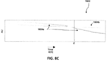
図8Bは、種々の実施形態に用いるのに適する感知材料に生じることのある変色の例を示す。具体的には、コラム1に示されている感知材料パッド1202aは第1の収着剤ベッドの後に位置する検出器106a内に置かれ、コラム2に示されている感知材料パッド1202bは第1の収着剤ベッドの下流側で第2の収着剤ベッドの後に位置する検出器106a内に置かれる。これらの同じ2つの感知パッド1202a、1202bの経時写真は9個の連続する時点で示され、左側の黒ずんだ材料は硫黄突破の存在を示し、燃料は左から右へ流れる。突破を示すことのできる実際の変色は、ポイントAおよびB(それぞれ第1および第2の収着剤ベッドからの突破イベントを示す)により示されている。すなわち、色感知材料は、1つ以上の望ましくない成分(例えば、硫黄など)の存在に基づいて変色することができる。例えば、いくつかの実施形態では、変色は、明るい(例えば、ライトブルー)色から黒ずんだ(例えば、ダークブラウン)色への変化を伴うことができる。
FIG. 8B illustrates examples of discoloration that may occur in a sensing material suitable for use in various embodiments. Specifically, the
代わりに、どの検出器106a〜106g、506、672、671、および/または706も、特定の望ましくない成分と関連する抵抗器における抵抗変化を検出することによって燃料流中の望ましくない成分を検出することができる。望ましくない成分と反応していない金属抵抗器(例えば、銅)は、特定の基準抵抗を有する。望ましくない成分(例えば、硫黄)は、特定の金属抵抗器と反応して(例えば、銅を少なくとも部分的に硫化銅に変化させる)抵抗器の抵抗率を変化させ、これにより望ましくない成分が存在することを示すことができる。例えば、銅金属ストリップ状の抵抗器を有する検出器は、比較的小さい抵抗率を有することができる。燃料流中に存在する有機硫黄化合物は、銅抵抗器と反応して硫化銅を形成して抵抗器ストリップの抵抗率を増大させ、これにより望ましくない成分の存在を示すことができる。前述した変色検出器システムによく似て、抵抗率変化を、特定の望ましくない成分および金属ストリップに従ってマッピングすることができる。さらなる代替の実施形態として、検出器106a〜106g、506、672、671、および/または706のいずれも、1つの特定の望ましくない成分または任意の数の望ましくない成分を検出するために人工鼻を使用することができる。燃料流中に存在する1つ以上の望ましくない成分を検出するために人工鼻を較正することができる。人工鼻は、反応性高分子先端付き光ファイバチャネルを含む。高分子は、望ましくない成分と反応するとその光学特性(例えば、反射率または屈折率)を変化させる。従って、チャネル内を伝播して高分子先端から反射する光は、先端が望ましくない成分と反応する前とは異なる特性を有する。
Instead, any
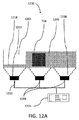
他の実施形態では、検出器106a〜106g、506、672、671、および/または706のうちの1つ以上は、図12Aに示されている光学検出器1200であることができる。一実施形態では、光学検出器1200は、望ましくない成分が存在すると変色するように構成された感知材料1202を含む。感知材料1202は、図8Aに関して前に記載した変色パッドであることができる。感知材料1202は、基板1204上に配置されたペイントまたは染料であることができる。ペイントまたは染料は、望ましくない成分にさらされると変色することができる。あるいは、感知材料1202は、望ましくない成分にさらされると変色する液体またはゲルであることができる。あるいは、感知材料1202は、望ましくない成分にさらされると変色する粒子または顆粒であることができる。流れを容易にするために半透明のハウジングにこれらの粒子を詰め込むことができる。いくつかの実施形態では、感知材料1202は、硫黄または硫黄含有化合物にさらされると変色するように、硫黄敏感である。他の実施形態では、感知材料1202は、シロキサン、酸素、または水などの他の望ましくない成分にさらされると変色する。いくつかの実施形態では、感知材料1202は、いくつかの異なる望ましくないコンポーネントに対して敏感である。感知材料1202は、その望ましくないコンポーネントの各々にさらされると識別可能な色に変化することができる。いくつかの実施形態では、感知材料1202は、燃料の流れが通過できるゼオライトまたは混合金属酸化物から作られた変色ペレットであることができる。いくつかの実施形態では、光学検出器1200は、感知材料1202の色の変化を示すように構成された少なくとも1つのセンサ1206を含む。一実施形態では、その少なくとも1つのセンサ1206は複数のセンサ1206である。各センサを、感知材料1202に面して配置することができる。例えば、感知材料1202が基板1204上に配置されたペイントまたは染料であるとき、少なくとも1つのセンサ1206を基板に面して配置することができる。少なくとも1つのセンサ1206の各々は変色検出器であることができる。変色検出器は、1つ以上の感色光検出器を含むことができる。変色検出器は、青色を検出する光検出器、緑色を検出する光検出器、および/または赤色を検出する光検出器を含むことができる。センサ1206は、各々の検出された色変化をデジタル信号として次のプロセッサ1224に出力することができる。代わりに、センサ1206は、各々の検出された色変化を、様々な直流(DC)電圧を有するアナログ出力として出力することができる。センサ1206は、コントローラエリアネットワーク(CAN)通信を介するなどして、有線信号または無線信号を介して信号を出力することができる。
In other embodiments, one or more of the
光検出器1200のいくつかの実施形態は、センサに結合された光源1208を含む。光源は、少なくとも1つのセンサ1206が感知材料1202の色を検出できるように感知材料1202を照明することができる。いくつかの実施形態では、少なくとも1つのセンサ1206は、赤色光、青色光、緑色光、および/または白色光検出器のうちの1つ以上を含むことができる。光源1208は、ランプまたは固体照明源などの電気的光源であることができる。いくつかの実施形態では、光源1208は1つ以上の発光ダイオード(LED)を含む。光源1208を、一定の発光出力を保証するため、あるいは様々な発光出力を可能にするために、電力調整回路(図示せず)に電気的に結合することができる。いくつかの実施形態は複数の光源1208を含む。
Some embodiments of the
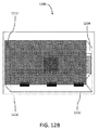
光検出器1200のいくつかの実施形態は、図12Bに示されているように、ハウジング1210を含む。ハウジング1210は、感知材料1202、少なくとも1つのセンサ1206、および1つまたは複数の光源1208を囲むことができる。ハウジング1210は、実質的に光に対して不透過性であることができる。例えば、その外側1212を、実質的に光を通さない金属またはプラスチックなどの材料から構成することができる。ハウジングの外側1212は、光の通過を阻止するために、黒色であることができる。いくつかの実施形態では、光不透過性ハウジング1210は、ハウジング1210外側1212内または外へ光が漏れるのを阻止し、少なくとも1つのセンサ1206により知覚される光の信号対雑音比を改善する。例えば、光不透過性ハウジング1210は、周辺光の変化によって感知材料1202が変色したように見えるようになって少なくとも1つのセンサ1206が誤り警報を示すことを阻止することができる。ハウジング1210の内側1214は、白などの明るい色であることができる。いくつかの実施形態では、明るい色の内側1214は、光源1208からの光を大いに拡散させ、光学検出器1200の動作を改善する。追加の実施形態は、ハウジングを囲む外部ケーシング1216を含む。ケーシング1216は、実質的に光に対して不透過性であることができる。いくつかの実施形態では、ケーシング1216およびハウジング1212は、光が入ることを許さずにガスが光学検出器1200に入ることを可能にする1つ以上の導管(図示せず)を有する。例えば、導管は、導管が方向を1回以上逆転させて、光を効果的に遮断するように、複数のベンドを持つことができる。
Some embodiments of the
再び図12Aを参照すると、光学検出器1200は基準材料1218を含むことができる。いくつかの実施形態では、基準材料1218は、望ましくない成分にさらされても変色しない。基準材料1218は、感知材料について前に記載した任意の材料から構成され得る。基準材料を基板1204上に配置することができる。いくつかの実施形態では、基準材料1218は、望ましくないコンポーネントがないときの感知材料1202と実質的に同じ色である。基準材料1218は感知材料1202と同じ材料から構成され得るけれども、基準材料1218は、基準材料1218が望ましくないコンポーネントにさらされることを阻止する透明なバリヤ(図示せず)を材料1218上に有することができる。代わりに、基準材料1218は、望ましくないコンポーネントにさらされても変色しない材料から構成され得るけれども、感知材料1202の当初の色と同じ色を有する。
Referring again to FIG. 12A, the
光学検出器1200は、基準材料の色の変化を感知する基準センサ1220をも含むことができる。基準センサを、少なくとも1つのセンサ1206について前に記述したように構成することができる。光学検出器1200は、基準センサ1220に結合された光源1222をも含むことができる。光源1222は、前述した光源1208のために適する任意の光源であってよい。光源1222は、基準センサ1220に結合されて、光源1208に関して前に記述したように基準材料1218を照明することができる。周辺の光または温度などの環境因子に起因する信号の変化を、検出されるべく意図されている燃料成分の存在に起因する信号の変化から分離するために、この基準センサ1220を使用することができる。
The
いくつかの実施形態では、光学検出器1200はプロセッサ1224に結合される。プロセッサは、図3A〜8Aに関して前に記述したように、バルブコントローラおよび/またはシステムコントローラであり得る。プロセッサ1224は、図10および図11に示されている計算装置1000またはマイクロプロセッサであり得る。プロセッサ1224はマイクロプロセッサであり得る。いくつかの実施形態では、プロセッサ1224は、少なくとも1つのセンサ1206から信号を受け取り、少なくとも1つのセンサ1206からの信号に応答して、感知材料1202の色を記録する。プロセッサ1224を、基準センサ1220から信号を受け取り、基準センサ1220からの信号に応答して、感知材料1206の色を記録するように構成することができる。一実施形態では、プロセッサ1224は、基準センサ1220からの信号の値を少なくとも1つのセンサ1218からの信号の値から引くように構成される(例えば、値の差)。これにより、キャビネットのドアが開かれるとき、あるいは疑似信号または他の光ノイズに起因して基準の色が違って見えるときに、信号対雑音比を高める効果を有することができる。プロセッサ1224を、感知材料の色の変化に対応する信号の信号対雑音比を高めるために信号平均値算出アルゴリズムを適用するように構成することができる。いくつかの実施形態では、プロセッサ1224は、複数の光学検出器1200の各々の中の1つ以上のセンサ1206から信号を受け取ることができ、それらを加え合わせることができる。例えば、第1の光学検出器1200からの信号を、流路のさらに下流の側にある第2の光学検出器1200からの信号に加えることができる。互いの上流側および下流側にある異なる検出器からの信号をこのように加え合わせれば、それらの合計信号応答を線形にすることができる。
In some embodiments,
いくつかの実施形態では、プロセッサ1224は、アラーム基準が満たされたときにアラーム信号を発するように構成される。アラーム基準を、いずれかのセンサ1206によってプロセッサ1224に送信された値の絶対値がセンサの較正済み値からプリセット値より大きく逸れているときに、満たすことができる。プリセット値は、許容し得ないレベルの望ましくない成分を示す変色に対応することができる。一実施形態では、アラーム信号を、基準が所定の量の時間にわたって満たされるときに、生成することができる。例えば、プロセッサ1224に送信される値がプリセット期間より長い期間にわたって(例えば、キャビネットのドアが典型的に開かれている期間より長い期間にわたって)較正済み値からプリセット値より大きく逸れている場合に限って、プロセッサ1224はアラーム信号を生成することができる。
In some embodiments, the
他の1つの実施形態では、アラーム信号は、センサ値が所定のアラーム値範囲の中に落ちたときに生成される。例えば、プロセッサ1224は、ありそうもない読み取り値と矛盾しない上側しきい値限界値を超えるセンサ値を、望ましくない成分の検出ではなくて光学検出器1200の故障として無視することができる。アラーム信号を、個々のセンサ値のいずれかが所定のしきい値を超えているときに、生成することができる。少なくとも1つのセンサ1206が赤色光を感知するように構成された少なくとも1つのセンサと、青色光を感知するように構成された少なくとも1つのセンサと、緑色光を感知するように構成された少なくとも1つのセンサとを含む1つの例として、プロセッサ1224は、緑色光センサだけからの信号がしきい値を超えるならば、アラームを生成することができる。少なくとも1つのセンサ1206に含まれる各センサは、プロセッサ1224に記憶される1つの異なるしきい値を持つことができる。
In another embodiment, the alarm signal is generated when the sensor value falls within a predetermined alarm value range. For example, the
いくつかの実施形態では、1つまたは複数の最小自乗回帰係数がプリセット値を超えるか、および/またはプリセット範囲外に落ちたときにアラーム信号が生成され得る。一実施形態では、最小自乗回帰は、少なくとも1つのセンサ1206によって伝達された値のセットなどの、データのセットに適合する一定のタイプの曲線を仮定し、その曲線タイプに関してのデータのエラーを最小にし、これによりその曲線適合の係数値を適合させる。この方法は、信号平均値算出および勾配解析を同時に効果的に行うことができる。さらに、最小自乗回帰は、データ点の標準誤差を計算することによって適合の品質を分析することができる。データが十分に良く適合しなければ、アラーム信号を送るべきではないと指令するために、「R^2」と呼ばれるこの偏差を利用することができる。最小自乗アルゴリズムを適用するための多くの計算手法を当業者であれば知っているはずである。
In some embodiments, an alarm signal may be generated when one or more least squares regression coefficients exceed a preset value and / or fall outside the preset range. In one embodiment, least squares regression assumes a certain type of curve that fits a set of data, such as a set of values transmitted by at least one
他の1つの実施形態では、アラーム信号は、時間に関してのセンサ値の二次導関数がプリセット値を超えるときに生成され得る。例えば、プロセッサ1224は、期間の経過に対して測定された少なくとも1つのセンサ1206から受信された一連の値に1つの曲線を適合させ、曲線の二次導関数を計算することができる。一定のしきい値を超える二次導関数は、センサ材料1202の色の変化の速度が加速していることを示し、光学検出器1200を通過する望ましくない成分の割合が増大しつつあることを示すことができる。代わりに、アラーム信号は、時間に関してのセンサ値の一次導関数がプリセット値を超えるときに生成され得る。例えば、プロセッサ1224は、期間の経過に対して測定された少なくとも1つのセンサ1206から受信された一連の値に対して1つの曲線を適合させ、曲線の一次導関数を計算することができる。一定のしきい値を超える一次導関数は、センサ材料1202の色が特定の速度で変化しつつあることを示し、望ましくない成分の一定のボリュームが光学検出器1200を通過しつつあることを示すことができる。プロセッサ1224は、センサ信号変化の正の勾配と負の勾配とを区別するように構成され得る。例えば、外部光汚染は、時間に関しての正の一次導関数により証明される、次第に度を増して正の検出器値を生じさせることができるのに対して、実際の有害物質検出は、時間に関しての負の一次導関数により証明される、次第に度を増して負の検出器値を生じさせることができる。当業者であれば、種々のデータセットを与えられたときに時間に関しての一次および二次導関数を計算するための多くの有効な計算方法を知っているはずである。
In another embodiment, an alarm signal may be generated when the second derivative of the sensor value with respect to time exceeds a preset value. For example, the
他の1つの実施形態では、少なくとも1つのセンサ1206により伝達された値のセットを、シグモイド・ベースの関数に適合することができる。例えば、そのシグモイド・ベースの関数はf(x)=1/(1+e-x)に基づくことができ、種々の係数および加算により修正することができる。1つの実施形態では、ベース関数を修正するために使用される係数は、少なくとも1つのセンサ1206から受信された色変化が係数値のしきい値を超える係数での適合化を必要とするときにアラーム信号が生成されるように、色変化限界値のためのアラームしきい値を表すことができる。当業者であれば、シグモイド・ベースの関数を用いるアルゴリズムのための多くの計算手法を知っているはずである。
In another embodiment, the set of values communicated by the at least one
さらなる実施形態において、センサ値の絶対値の合計がプリセット値を超えるときにアラーム信号が生成される。従って、センサ1206が赤色、青色、および緑色変化値を感知する場合には、プロセッサ1224は、いずれか1つの値がしきい値を超えるか、あるいはどの1つの値もしきい値を超えないけれども加え合わされた値の組み合わせがしきい値を超えるならば、アラーム信号を生成することができる。プロセッサ1224を、センサ1206の正および負の読み取り変化を区別するように構成することができる。プロセッサ1224を、各々の個々のセンサ1206のために異なるアラームアルゴリズムを適用するように構成することができる。例えば、図3Dに描かれている実施形態では、プロセッサ1224は、燃料電池スタックに入る直前で燃料管路内に置かれた光学検出器1200内のセンサについて燃料中の望ましくない成分のより多くの含有量がシステムに供給されつつあることを示す状態変化が知覚されたならば、偽陽性の割合がより多くなるという代償を払って、すぐにアラームを生成するように設計されたアルゴリズムを使用することができる。代わりに、プロセッサ1224は、第2のベッドが第1のベッドを突破した硫黄を全て吸収するので2つの主収着剤ベッドの間で管路内に置かれた光学検出器1200内のセンサにおいてより低い割合の偽陽性を生じさせるために、応答は比較的に速くはないけれども経時変化を評価する(例えば、一次および/または二次導関数を用いて)アルゴリズムを使用することができる。プロセッサ1224は、任意のセンサ1206を用いてアラームを生成するために前述したアルゴリズムの任意の組み合わせを用いることができる。一例として、複数のアラームアルゴリズムが並行して動作し、これらのアラーム判定基準のうちの所与の数のアラーム判定基準が満たされたならば、アラーム検出が確認され得る。
In a further embodiment, an alarm signal is generated when the sum of the absolute values of the sensor values exceeds a preset value. Thus, if the
さらなる実施形態では、主流路を通る(例えば、1つ以上の主収着剤ベッドを通る)燃料の流れを、光学検出器1200を通る流れと比較することができる。そのような比較を行うために、瞬時流量に基づくかあるいは各経路を通って流れた総ボリュームに基づいて、主流路の測定値およびセンサ流の測定値を取ることができる。種々の実施形態において、主経路流のセンサ流に対する比は、センサ材料が循環した総ボリュームの数に対する1つ以上の主収着剤ベッドが循環した総ボリュームの数の示度として使用され得る。1つ以上の主収着剤ベッドと比べてセンサ材料がどれほど劣化しているかを判定するためにこの比を使用することができ、これによりセンサ材料において示される変色を1つ以上の主収着剤ベッドの劣化の反映とすることを可能にする。
In further embodiments, the flow of fuel through the main flow path (eg, through one or more main sorbent beds) can be compared to the flow through the
種々の実施形態において、システムのためのアラームしきい値は、主流路内の流量とセンサ流路内の流量との比に基づいて開発され得る。すなわち、種々の流量比において、それを超えれば、主流収着剤ベッドの健全性が劣化していることを示すことになる種々のしきい値が存在する。例えば、システムがセンサ流1ボリュームに対して主経路流1000ボリュームの流量比で動作しているとすれば、センサによって示された変色の値が100より大きければ、アラームを立てるべきであることが分かり得る。同じシステムについて、流量比がセンサ流1ボリュームに対して主経路流2000ボリュームであれば、センサによって示された変色の値が130より大きければ、アラームを立てるべきであること分かり得る。従って、種々の実施形態において、システムは、任意の所与の流量比で許容し得るセンサ値を規定する流量比しきい値関数を持つことができる。そのような許容し得るセンサ値は、検出器値、動作開始以降の検出器値変化、検出器勾配などを含むがこれらに限定はされない任意の数のパラメータに関して提供され得る。 In various embodiments, an alarm threshold for the system may be developed based on the ratio of the flow rate in the main flow path and the flow rate in the sensor flow path. That is, at various flow ratios, there are various thresholds that would indicate that the integrity of the mainstream sorbent bed has been degraded. For example, if the system is operating at a flow ratio of 1000 volumes of main path flow to 1 volume of sensor flow, an alarm should be raised if the discoloration value indicated by the sensor is greater than 100. I understand. For the same system, it can be seen that if the flow ratio is 2000 volumes of main path flow to 1 volume of sensor flow, an alarm should be raised if the discoloration value indicated by the sensor is greater than 130. Thus, in various embodiments, the system can have a flow ratio threshold function that defines an acceptable sensor value at any given flow ratio. Such acceptable sensor values may be provided for any number of parameters, including but not limited to detector values, detector value changes since the start of operation, detector slope, and the like.
いくつかの実施形態では、所与の時における特定のセンサ1206の信号特性を、同じセンサ1206について前に測定された信号特性と比べることができる。例えば、所与の時点における感知材料での赤色のセンサ1206の検出を示す信号を、その初めの数時間の動作の間の同じセンサ1206による感知材料での赤色の検出を示す信号と比べることができる。さらに、いくつかの実施形態では、所与の時点で測定された特定のセンサ1206の信号特性を色基準サンプルと比較することができる。例えば、どのセンサ1206に対する基準線を確立するためにも、色較正カートリッジが存在し得る。
In some embodiments, the signal characteristics of a
他の1つの実施形態では、特定のセンサ1206からの信号を、センサ1206の種々の動作状態における変動を補正するために、処理することができる。センサ1206に対して変化し得るいくつかの動作状態の例は、いくつかを挙げれば、気体媒体流量、気体媒体温度、気体媒体圧力、センサ温度、センサキャビネット開放である。これらの変化する動作状態に基づいてセンサ信号を正規化値に補正することにより、偽アラームを回避することができる。
In another embodiment, the signal from a
図2〜8Aに関して前に記述したように、1つ以上の光学検出器1200を燃料電池アセンブリに置くことができる。いくつかの実施形態では、燃料電池アセンブリは、図2〜8Aに関して前に記述した燃料電池スタック105と、燃料電池スタックに流体的に接続された、図2〜8Aに関して前に記述した燃料処理モジュール280、380a、380b、380c、380d、480a、480b、480c、480d、500、および/または600などの燃料処理モジュールとを含むことができる。1つ以上の光学検出器1200を、図3A〜8Aに関して前に記述した検出器106a〜106g、506、672、671、および/または706のいずれかとして使用することができる。1つ以上の光学検出器1200を、図3A〜8Aに関して前に記述した検出器106a〜106g、506、672、671、および/または706のいずれかにおいてコンポーネントとして使用することができる。従って、1つ以上の光学検出器1200を、単独でまたは追加の検出器エレメントと組み合わせて、図7に関して前に説明したように、燃料電池システムの燃料入口管路内および/またはスリップストリーム管路内に置くことができる。複数の光学検出器1200が存在する場合には、各検出器1200を、燃料電池システムの燃料入口管路に沿って異なる位置に置くことができる。1つ以上の光学検出器1200は、1つ以上のプロセッサ1224と組み合わされて、バルブ102a,104、124a、122a、502a、682a、681a、および/または636aなどの、図2〜8Aに関して前に記述したバルブのうちの1つ以上を調整することができる。1つ以上の光学検出器1200および1つ以上のプロセッサ1224は、バルブに、図2〜8Aに関して前に記述したどの動作をも実行させることができる。
One or more
1つの非限定的な例として、図12Cに描かれているように、燃料電池アセンブリは、燃料電池スタック105と、燃料電池スタック105に流体的に接続されて燃料を燃料源101から燃料電池スタックに向ける燃料処理モジュール1280とを含むことができる。燃料処理モジュール1280は、主収着剤ベッド82aと、予備収着剤ベッド82bと、予備収着剤ベッド82bをバイパスする燃料の流れを制御するように構成されたバルブ102aと、主収着剤ベッド82a内の望ましくない成分を検出するために図12A〜12Bに関して前に記述した1つ以上の光学検出器1200を含む光検出システムとを含む。開いているバルブ102aは、燃料の流れの全部または大部分に主収着剤ベッド82aを通過させ、導管91を介して予備収着剤ベッド82bをバイパスさせるように構成されている。望ましくない成分が検出されると、バルブ102aは、導管92を介して全ての燃料の流れに予備収着剤ベッド82bを通過させるように閉じられるか、あるいは導管92を介してより多くの燃料の流れに予備収着剤ベッド82bを通過させるように部分的に閉じられる。燃料処理モジュール1280は、図2〜8Aに関して前に記述したように、バルブ102aが開いているとき定常状態動作中に予備収着剤ベッド82bの周囲を回って流れるように燃料を向けるためにバイパス導管91を使用することができる。
As one non-limiting example, as depicted in FIG. 12C, the fuel cell assembly includes a
燃料処理モジュール1280は、図2〜8Aに関して前に記述したように、バルブ102aが閉じられているときに燃料に予備収着剤ベッド82bを通過させるために追加の導管92および93を使用することができる。燃料処理モジュール1280を、図2〜8Aに関して前に描かれたように、追加のあるいはフェイルセーフのバルブ104により調整される燃料入口導管94を介して燃料電池スタック105に接続することができる。種々の導管およびバルブは、I/O接続部88、88a〜88cに接続することができる。燃料処理モジュール1280は、図2〜8Aに関して前に記述したように、主収着剤ベッド82a上/内に置かれた追加の検出器106b、106c、および106dを含むことができる。この追加の検出器106b、106c、および106dは、図12A〜12Bに関して前に記述した光学検出器1200を含むことができる。
The
アラーム信号が生成される前に燃料の流れの小部分に予備収着剤ベッド82bを通過させるとともに燃料の流れの大部分に主収着剤ベッド82aを通過させるようにバルブ102aを開くことができる。アラーム信号が生成されたときに燃料の流れの全部または大部分に予備収着剤ベッド82bを通過させるとともに燃料の流れのゼロ部分または小部分に主収着剤ベッド82aを通過させるためにバルブ102aを閉じることができる。バルブ102aは、アラーム信号が生成される前に、導管92内の追加バルブが閉じられるとともにバルブ102aが開いているならば、全ての燃料の流れに主収着剤ベッド82aを通過させるように構成され得る。バルブ102aを、アラーム信号が生成され、バルブ102aが開いているときに、全ての燃料の流れに予備収着剤ベッド82bを通過させるように構成することができる。
Before the alarm signal is generated, the
図13は、燃料電池システムにおいて望ましくない成分を検出する実施形態の方法1300を示す。この方法1300は、ステップ1302において、望ましくない成分が存在すれば変色するように構成された感知材料と、感知材料の変色を示すように構成された少なくとも1つのセンサとを含む光学検出システムを設けるステップを含む。センサは、対応する光源に結合される。感知材料、センサ、および光源は、ハウジングに封入される。いくつかの実施形態では、これは、図12A〜12Bに関して前に開示したように実行される。
FIG. 13 illustrates an
方法1300は、燃料電池システムの燃料流中の望ましくない成分を検出するステップを含むことができる(ステップ1304)。いくつかの実施形態では、望ましくない成分の検出は、図12A〜12Cに関して前に開示したように実行され得る。
方法1300は、アラーム基準が満たされたときにアラーム信号を生成するステップを含むことができる(ステップ1306)。いくつかの実施形態では、望ましくない成分の検出は、図12A〜12Cに関して前に開示したように実行され得る。
The
図14は、燃料電池システムにおいて望ましくない成分を検出する他の1つの実施形態の方法1400を示す。この方法1400は、ステップ1402において、望ましくない成分が存在すれば変色するように構成された感知材料と、感知材料の変色を示すように構成された少なくとも1つのセンサとを含む光学検出システムを設けるステップを含む。センサは、対応する光源に結合される。望ましくない成分が存在しても変色しない基準材料、および基準材料の変色を示すように構成されて光源に光学的に結合された基準センサも設けられる。いくつかの実施形態では、これは、図12A〜12Cに関して前に開示したように実行される。
FIG. 14 illustrates another
方法1400は、燃料電池システムの燃料流中の望ましくない成分を検出するステップをさらに含むことができる(ステップ1404)。いくつかの実施形態では、これは、図12A〜12Cに関して前に開示したように実行される。
The
方法1400は、アラーム基準が満たされたときにアラーム信号を生成するステップをさらに含むことができる(ステップ1406)。いくつかの実施形態では、これは、図12A〜12Cに関して前に開示したように実行される。
The
図15は、燃料電池システムにおいて望ましくない成分を検出する他の1つの実施形態の方法1500を示す。この方法1500は、望ましくない成分が存在すれば変色するように構成された感知材料と、赤色センサ、緑色センサおよび青色センサを含む少なくとも1つのセンサと、各色センサから色値を受け取るように構成されたプロセッサとを含む光学検出システムを設けるステップ1502を含むことができる。いくつかの実施形態では、これは、図12A〜12Bに関して前に開示したように実行される。
FIG. 15 illustrates another
方法1500は、各色センサから個々の値をプロセッサに送るステップを含むことができる(ステップ1504)。いくつかの実施形態では、これは、図12A〜12Cに関して前に開示したように実行される。
The
方法1500は、アラーム基準が満たされたときにアラーム信号を生成するステップを含むことができる(ステップ1506)。いくつかの実施形態では、これは、図12A〜12Cに関して前に開示したように実行される。
The
燃料電池スタックの性能測定値による突破イベント/活性低下の検出
図9は、燃料電池スタックが望ましくない成分で活性低下するときの、数個の燃料電池スタックからの燃料電池性能測定値を示す。1つの実施形態では、図3A、図3D、図4A、図4D、および図6に関して図に示して記述したモニタ110は、燃料電池スタック性能の劣化(または燃料電池活性低下を引き起こす突破イベント)を検出することによって燃料電池スタックの燃料電池活性低下を検出することができる。
Detecting Breakthrough Event / Decrease in Activity with Fuel Cell Stack Performance Measurements FIG. 9 shows fuel cell performance measurements from several fuel cell stacks when the fuel cell stack is deactivated with undesirable components. In one embodiment, the
図9に示されている非限定的図解において、モニタ110は、燃料電池スタック105を動作させている間に個々のスタック電圧および/または燃料電池システムの電流を測定するか、あるいは複数の燃料電池スタック105を動作させている間に燃料電池システムの電流を測定することができる。燃料電池スタック105は、測定されたスタック電圧901および測定されたシステム電流902を持つことができる。図9は、おおよそ燃料電池スタック(あるいは複数の燃料電池スタック)が硫黄にさらされるとき、約36時間の動作の後にスタック電圧の約5.5%の僅かな低下を示す。図に示されているように、望ましくない成分による燃料電池活性低下時でかつ燃料電池活性低下後に、電流はほぼ一定のままである。その後数日にわたって、スタック電圧は振動し、ついには約90時間(あるいは初めて硫黄にさらされた後おおよそ2日)で当初の値の約15%まで低下する。同時にシステム電流はクラッシュする。
In the non-limiting illustration shown in FIG. 9, the
1つの実施形態では、燃料電池スタック監視システム(例えば、モニタ110)は、燃料電池スタック電圧が所与の燃料流量について少なくとも5%低下したとき、燃料電池スタック105が突破イベントからもたらされる望ましくない成分(例えば、硫黄)にさらされていたことを検出することができる。モニタ110は、所与の燃料流量についてシステム電流が一定であるときにスタック電圧の振動と関連して約5〜15%の電圧低下を測定したときも、硫黄などの望ましくない成分による活性低下に帰することのできる燃料電池活性低下または突破イベントを検出することができる。従って、システムが出力電流のクラッシュを経験する前に、救済ステップ(例えば、燃料電池スタックからの電流引き出しを止めるとともに燃料電池スタックへの燃料の流れを止める、燃料の流れの少なくとも一部分に異なる収着剤ベッドを通過させる、異なる燃料源を選ぶ、燃料電池スタックへの燃料の流れを減らす、あるいは他の保守点検など)を行うことができる。
In one embodiment, the fuel cell stack monitoring system (e.g., monitor 110) may be an undesirable component that causes the
種々の実施形態において、アラーム信号は、時間に関しての燃料電池スタック電圧および/または電流値に基づいて生成され得る。いくつかの実施形態では、燃料電池スタック監視システムのプロセッサは、1つの期間の経過に対して測定された一連の電圧および/または電流値に1つの曲線を適合させ、曲線の一次および/または二次導関数を計算することができる。例えば、一次導関数が負のしきい値より下まで低下したならば(すなわち、電圧値の曲線が急速に下がりつつあることを示したならば)、所与の燃料流量について(例えば6時間以下など、3時間以下などの所与の期間にわたる)5〜15%などの少なくとも5%の電圧降下を指摘することができる。他の1つの例では、燃料電池スタック電圧測定値の一次導関数の値が正から負へあるいは逆に転換するか、および/または二次導関数が正から負の値へ転換したならば(すなわち、電圧値の曲線の陥凹部/曲率の転換を示したならば)、スタック電圧の振動を指摘することができる。種々の実施形態において、当業者であれば、所与の種々のデータセットについて時間に関しての一次および二次導関数を計算する多くの有効な計算方法を知っているはずである。 In various embodiments, the alarm signal may be generated based on the fuel cell stack voltage and / or current value with respect to time. In some embodiments, the processor of the fuel cell stack monitoring system fits a curve to a series of voltage and / or current values measured over the course of a period of time, and the primary and / or second of the curve. The second derivative can be calculated. For example, if the first derivative drops below a negative threshold (ie, indicates that the voltage curve is rapidly decreasing), for a given fuel flow (eg, 6 hours or less) A voltage drop of at least 5%, such as 5-15% (for a given period, such as 3 hours or less) can be pointed out. In another example, if the value of the first derivative of the fuel cell stack voltage measurement changes from positive to negative or vice versa, and / or if the second derivative changes from positive to negative ( That is, if it shows a recess / curvature shift in the voltage value curve), then the stack voltage oscillation can be pointed out. In various embodiments, those skilled in the art will know many effective calculation methods for calculating first and second derivatives with respect to time for a given variety of data sets.
脱硫システムの例
1つの非限定的な例において、図12A〜12Bに関して前に記述した光学検出器1200は、種々の望ましくない成分の硫黄種を除去する収着剤ベッドに関連する種々の機能を実行するように構成された脱硫システムの一部であることができる。1つの実施形態では、脱硫システムは、少なくとも1つの収着剤ベッドと、少なくとも1つの硫黄センサをともなって構成された少なくとも1つの光学検出器とを含むことができる。
Desulfurization System Example In one non-limiting example, the
いくつかの実施形態では、脱硫システムの動作は、少なくとも1つの収着剤ベッドの交換のための調達、スケジューリングおよび実行のために十分な時間を提供するように構成され得る。いくつかの実施形態では、脱硫システムの動作は、少なくとも1つの収着剤ベッドの時期尚早の交換を最小にし、それにより収着剤ベッド利用を最大にすることができる。 In some embodiments, the operation of the desulfurization system may be configured to provide sufficient time for procurement, scheduling and execution for replacement of at least one sorbent bed. In some embodiments, operation of the desulfurization system can minimize premature replacement of at least one sorbent bed, thereby maximizing sorbent bed utilization.
種々の実施形態において、光学検出器を2つの硫黄センサをともなって構成することができ、各々の1つは光学検出器の入口燃料流および出口燃料流に結合される。その2つの硫黄センサは、硫黄が存在すると変色するカートリッジ(例えば、パッド)の色を監視する光学センサであることができる。一例では、光学検出器はSulfaTrack(登録商標)検出器であることができ、これは気相システム中の非常に低いレベルの硫黄を検出するためにサルファトラップ社 (SulfaTrap, Inc.)により市販されている。SulfaTrack(登録商標)検出器は<100ppbの硫黄除去システム突破の視覚指示を提供することができる。いくつかの実施形態では、SulfaTrack(登録商標)検出器を含む脱硫システムは、収着剤ベッド性能のリアルタイム監視およびそれに基づく自動ベッド切り替えを提供することができる。 In various embodiments, the optical detector can be configured with two sulfur sensors, each one coupled to the optical detector inlet and outlet fuel streams. The two sulfur sensors can be optical sensors that monitor the color of a cartridge (eg, a pad) that changes color when sulfur is present. In one example, the optical detector can be a SulfaTrack® detector, which is marketed by SulfaTrap, Inc. to detect very low levels of sulfur in a gas phase system. ing. The SulfaTrack® detector can provide a visual indication of breaking through a <100 ppb sulfur removal system. In some embodiments, a desulfurization system that includes a SulfaTrack® detector can provide real-time monitoring of sorbent bed performance and automatic bed switching based thereon.
それらが1つ以上の収着剤ベッドについて望ましくない成分の突破を適切に検出することを保証するために、光学検出器の試験を行うことができる。例えば、第1の収着剤ベッドの出口の第1の光学検出器と、第2の収着剤ベッドの出口の第2の光学検出器とを有して構成された脱硫システムにおいて、第1および第2の光学検出器の各々を、入口流および出口流に結合された硫黄センサを伴って構成することができる。光源を用いて、入口および出口センサは、変色(例えば、白/透明から黄色や、青から茶色へなど)に基づいて硫黄を感知することができる。実際の硫黄突破イベントが起こったとき(または試験を目的として起こされたとき)、時間に関しての各光学検出器の入口流および出口流での色感知値は、同じ期間に関しての実際の燃料電池スタック性能(例えば、図9に示されているような電圧および/または電流)の測定値と比較され得る。このようにして、急速に変化する出口センサ値が同じ期間中の硫黄被曝に起因する燃料電池スタック性能の低下に対応するならば、硫黄被曝が正しく検出されたことを確かめることができる。 Optical detectors can be tested to ensure that they properly detect the breakthrough of undesirable components for one or more sorbent beds. For example, in a desulfurization system comprising a first optical detector at the outlet of a first sorbent bed and a second optical detector at the outlet of a second sorbent bed, Each of the second optical detectors can be configured with a sulfur sensor coupled to the inlet and outlet streams. With a light source, the inlet and outlet sensors can sense sulfur based on a color change (eg, white / transparent to yellow, blue to brown, etc.). When an actual sulfur breakthrough event occurs (or for test purposes), the color sensing values at each optical detector inlet and outlet flow with respect to time are the actual fuel cell stacks for the same period. It can be compared to measurements of performance (eg, voltage and / or current as shown in FIG. 9). In this way, if the rapidly changing outlet sensor value corresponds to a decrease in fuel cell stack performance due to sulfur exposure during the same period, it can be ascertained that sulfur exposure was correctly detected.
脱硫システムのためのそのような比較の例が図8C〜8Dのグラフに示されている。グラフ1602は、2ベッド試験セットアップにおける第2の収着剤ベッドの出口に配置された光学検出器1200の出力に対応する。線1604aは、時間の経過にともなう入口センサの色読み取り値を反映し、線1604bは、時間の経過にともなう出口センサによる色読み取り値を反映する。データ値1604a、1604bは、図8Bに示されているものと類似する、パッドの色変化の感知された色にプロットされた白色光を検出した事例として記録され得る。時点Eにおいて、入口センサのデータ値1604a、1604bは、顕著なパッドの変色を示し始めることができ、これは、第2の収着剤ベッドからの燃料の流れが硫黄を含んでいること(すなわち、硫黄突破)を意味する。グラフ1606は、時間の経過に伴う燃料電池スタック出力電圧測定値に対応し、これは、例えば図8Dに示されているポイントBから始まる硫黄突破に起因する性能ロス(出力電圧の低下)を示す。ポイントEがポイントBに期待通りの時間窓だけ先行することが分かったならば、硫黄突破を識別する光検出システムの能力が立証され得る。従って、時点E後ではあるが、時点Bよりは前に、1つまたは複数の収着剤ベッド82aを交換するか、および/または1つまたは複数の予備ベッド82bを活性化させるべきである。ポイントCで、スタックは回復不能のダメージを被る。ポイントDは、スタックの出力電圧に対する電気化学的インピーダンス分光法試験スキャンの効果を示し、その詳細は、その全体が本願明細書において参照により援用されている、米国特許第8,652,697号明細書(特許文献2)に記載されている。
An example of such a comparison for a desulfurization system is shown in the graphs of FIGS.
従って、種々の実施形態において、1つまたは複数の収着剤ベッド82の健全性の流量比ベースの反映として検出器1200を使用することができ、ポイントEは、検出器読み取り値が、1つまたは複数の収着剤ベッド82の健全性がアクションを必要としていることを示すのに十分な顕著な総合変色(すなわち、総データ値1604a、1604b)を示したことを確認する。いくつかの実施形態では、センサデータ値から突破イベントを識別するために使用される計算に導関数を追加的にまたは代替として使用することができる。例えば、合計センサデータ値(図示せず)を形成するために入口センサのデータ値1604aおよび出口センサのデータ値1604bを加え合わせることができる。種々の実施形態において、合計センサデータ値のために一次導関数および/または二次導関数を計算することができる。一次導関数および/または二次導関数計算が、あらかじめセットされたしきい値より下がったならば、硫黄突破を検出してアラームをトリガすることができる。
Accordingly, in various embodiments, the
コンピュータ制御エレメント
バルブコントローラ102b、124b、122b、502b、682b、681b、636b、モニタ110、システムコントローラ890、およびデータベース811などの制御エレメントを、プロセッサ、メモリ、および特定の機能を実行する命令でプログラムされている他のコンポーネントを含む計算装置(コンピュータなど)を用いて実装するか、あるいは指定された機能を実行するように設計されたプロセッサで実装することができる。プロセッサは、本願明細書に記載された種々の実施形態の機能を含む種々の機能を実行するソフトウェア命令(アプリケーション)によって構成され得る任意のプログラ無可能なマイクロプロセッサ、マイクロコンピュータ、または1つもしくは複数のマルチプロセッサチップであることができる。いくつかの計算装置では、複数のプロセッサを設けることができる。通例、ソフトウェアアプリケーションは、それらがアクセスされてプロセッサにロードされる前に内部メモリに記憶され得る。いくつかの計算装置では、プロセッサは、アプリケーションソフトウェア命令を記憶するのに十分な内部メモリを含むことができる。
Computer control
図10は、どの実施形態に用いるのにも適する計算装置のブロック図である。そのような計算装置1000は、通例、揮発性メモリ1002と、ディスクもしくはソリッドステートフラッシュドライブ1003などの大容量不揮発性メモリとに結合されたプロセッサ1001を含む。通例、ソフトウェアアプリケーションは、それらがアクセスされてプロセッサ1001にロードされる前に内部メモリ1002にストアされ得る。プロセッサ1001は、アプリケーションソフトウェア命令をストアするのに十分な内部メモリを含むことができる。
FIG. 10 is a block diagram of a computing device suitable for use in any embodiment. Such a
計算装置1000は、プロセッサ1001に結合されたフラッシュドライブ1004およびコンパクトディスク(CD)ドライブ1005をも含むことができる。通例、計算装置1000は、マウス1007などのポインティングデバイス、キーボード1008などのユーザ入力デバイスおよびディスプレイ1009をも含み得る。計算装置1000は、データ接続もしくはネットワーク接続を確立するか、あるいはUSBもしくはFireWire(登録商標)コネクタソケットなどの外部メモリデバイスを受け入れるために、プロセッサ1001に結合されたいくつかのコネクタポート1006をも含むことができる。1つのノートブック機器構成では、コンピュータアートにおいてよく知られているように、コンピュータハウジングは、ポインティングデバイス1007、キーボード1008およびディスプレイ1009を含む。
The
計算装置1000はデスクトップフォームファクタを用いるものとして図に示されているが、図に示された形に限定されることを意図していない。例えば、計算装置1000のコンポーネントのいくつかあるいは全部を、デスクトップコンピュータ、ラップトップコンピュータ、ミニコンピュータ、タブレット、スマートフォン、または携帯情報端末(PDA)として実装することができる。
Although the
バルブコントローラ102b、124b、122b、502b、682b、681b、636b、モニタ110、システムコントローラ890、およびデータベース811などの種々の計算装置を、図11に示されているサーバ1100などの、市販されている多様なサーバデバイスのうちの任意のサーバデバイス上でも実装することができる。そのようなサーバ1100は、通例、揮発性メモリ1102、およびディスクドライブ1103などの大容量不揮発性メモリに結合されたプロセッサ1101を含む。サーバ1100は、プロセッサ1101に結合された外部ドライブ、コンパクトディスク(CD)、またはDVDディスクドライブ1104を含むこともできる。サーバ1100は、他のブロードキャストシステムコンピュータおよびサーバに結合されたローカルエリアネットワークなどの、ネットワーク1112とのデータ接続を確立するためにプロセッサ1101に結合されたネットワークアクセスポート1106をも含むことができる。サーバ1100は、キーボード1108、ポインタデバイス(例えば、コンピュータマウス1110)、およびディスプレイ1109などのオペレータインターフェイスをも含むことができる。
Various computing devices such as
プロセッサ1001および1101は、次の種々の実施形態の機能を含む、多様な機能を実行するソフトウェア命令(アプリケーション)により構成され得る任意のプログラム可能なマイクロプロセッサ、マイクロコンピュータ、または1つもしくは複数のマルチプロセッサチップであることができる。いくつかのモバイル受信装置では、無線通信機能に専用される1つのプロセッサおよび他のアプリケーションを動作させるのに専用される1つのプロセッサなど、複数のプロセッサを設けることができる。通例、ソフトウェアアプリケーションを、それらがアクセスされてプロセッサ1001および1101にロードされる前に内部メモリ1002、1102、およびまたは1103に記憶することができる。プロセッサ1001および1101は、アプリケーションソフトウェア命令を記憶するのに十分な内部メモリを含むことができる。
The
本願明細書において開示された実施形態と関連して記載された種々の実例となる論理ブロック、モジュール、回路、およびアルゴリズムステップを、電子ハードウェア、コンピュータソフトウェア、または両者の組み合わせとして実装することができる。ハードウェアおよびソフトウェアのこの互換性を明瞭に示すために、種々の実例となるコンポーネント、ブロック、モジュール、回路、およびステップは前に概してそれらの機能性という言い方で記述されている。そのような機能性がハードウェアとして実装されるかあるいはソフトウェアとして実装されるかは、個々のアプリケーションと、システム全体に課される設計制約による。当業者は、記述された機能性を各々の特定のアプリケーションのために種々の仕方で実行することができるが、そのような実行決定は本発明の範囲からの逸脱を引き起こすと解されるべきではない。 The various illustrative logic blocks, modules, circuits, and algorithm steps described in connection with the embodiments disclosed herein can be implemented as electronic hardware, computer software, or a combination of both. . To clearly illustrate this interchangeability of hardware and software, various illustrative components, blocks, modules, circuits, and steps have been described above generally in terms of their functionality. Whether such functionality is implemented as hardware or software depends on the individual application and design constraints imposed on the overall system. Those skilled in the art can implement the described functionality in various ways for each particular application, but such implementation decisions should not be construed as causing deviations from the scope of the present invention. Absent.
本願明細書で開示された態様と関連して記載された種々の実例となるロジック、論理ブロック、モジュール、および回路を、汎用プロセッサ、デジタル信号処理装置(DSP)、特定用途向け集積回路(ASIC)、フィールドプログラマブルゲートアレイ(FPGA)、あるいは本願明細書に記載された機能を実行するように設計された他のプログラム可能な論理装置、ディスクリートゲートもしくはトランジスタロジック、ディスクリートハードウェアコンポーネント、またはそれらの任意の組み合わせを用いて実装するかあるいは実行することができる。汎用プロセッサはマイクロプロセッサであり得るが、代わりに、プロセッサは任意の在来のプロセッサ、コントローラ、マイクロコントローラ、または状態マシンであってもよい。プロセッサを、例えば、DSPおよびマイクロプロセッサ、複数のマイクロプロセッサ、DSPコアと関連する1つ以上のマイクロプロセッサ、または任意の他のそのような構成の組み合わせなど、複数の計算装置の組み合わせとして実装することもできる。代わりに、いくつかのブロックまたは方法を、所与の機能に特有の回路により実行することができる。 Various illustrative logic, logic blocks, modules, and circuits described in connection with the aspects disclosed herein may be used for general purpose processors, digital signal processors (DSPs), application specific integrated circuits (ASICs). , A field programmable gate array (FPGA), or other programmable logic device, discrete gate or transistor logic, discrete hardware components, or any of them designed to perform the functions described herein It can be implemented or implemented using a combination. A general purpose processor may be a microprocessor, but in the alternative, the processor may be any conventional processor, controller, microcontroller, or state machine. A processor is implemented as a combination of multiple computing devices such as, for example, a DSP and microprocessor, multiple microprocessors, one or more microprocessors associated with a DSP core, or any other combination of such configurations. You can also. Alternatively, some blocks or methods can be performed by circuitry that is specific to a given function.
前述した方法についての記述は、単に実例として提供したのであって、種々の実施形態のステップが提示された順に実行されなければならないことを必要としたり、意味したりするように意図されたものではない。当業者であれば認識することができるように、前述した実施形態におけるステップの順序はいかなる順序で実行されてもよい。「その後」、「それから」、「次いで」などの語は必ずしもステップの順序を限定するべく意図してはいない。これらの語は、方法の記述を通して読み手を案内するために使用され得る。さらに、例えば冠詞を用いた単数形での特許請求の範囲の構成要素への言及は、その構成要素を単数形に限定すると解釈されるべきではない。 The foregoing description of the method is provided merely as an example and is not intended to require or imply that the steps of the various embodiments must be performed in the order presented. Absent. As can be appreciated by those skilled in the art, the order of the steps in the embodiments described above may be performed in any order. The terms “after”, “then”, “then”, etc. are not necessarily intended to limit the order of the steps. These words can be used to guide the reader through the description of the method. Further, reference to an element in a claim in the singular, for example using the article, should not be construed as limiting the element to the singular.
開示された態様の前述したような記述は、当業者が本発明を製造したりあるいは使用したりすることを可能にするために提供されている。これらの態様に対する種々の改変は当業者であれば容易に認識できるはずである。本願明細書において定義された包括的な原理は、本発明の範囲から逸脱せずに他の態様にも適用され得る。従って、本発明は、本願明細書に示された態様に限定されるべく意図されてはおらず、本願明細書において開示された原理および新規な特徴と矛盾しない最も広い範囲を与えられるべきである。 The previous description of the disclosed aspects is provided to enable any person skilled in the art to make or use the present invention. Various modifications to these embodiments should be readily recognized by those skilled in the art. The generic principles defined herein can be applied to other embodiments without departing from the scope of the present invention. Accordingly, the present invention is not intended to be limited to the embodiments shown herein but is to be accorded the widest scope consistent with the principles and novel features disclosed herein.
Claims (113)
前記望ましくない成分が存在すれば変色するように構成された感知材料と、
前記感知材料の変色を示すように構成された少なくとも1つのセンサと、を備え、
前記感知材料、前記センサおよび光源は、ハウジング内に封入されるシステム。 An optical detection system for detecting undesirable components in a fuel cell system, comprising:
A sensing material configured to change color if the undesirable component is present;
At least one sensor configured to indicate a discoloration of the sensing material;
The sensing material, the sensor and the light source are encapsulated in a housing.
前記ハウジングは、光に対して不透過性である外側を有し、
前記少なくとも1つのセンサは、対応する光源に結合されるシステム。 The system of claim 1, wherein
The housing has an outer side that is impermeable to light;
The system wherein the at least one sensor is coupled to a corresponding light source.
前記ハウジングは、白色の内側を有するシステム。 The system of claim 1, wherein
The housing has a white interior.
複数のセンサおよび複数の光源をさらに備えるシステム。 The system of claim 2, wherein
A system further comprising a plurality of sensors and a plurality of light sources.
前記ハウジングは、光に対して不透過性である外部ケーシング内にさらに封入されるシステム。 The system of claim 2, wherein
The system wherein the housing is further encapsulated in an outer casing that is impermeable to light.
前記望ましくない成分が存在しても変色しない基準材料、および前記基準材料の変色を示すように構成されて光源に光学的に結合された基準センサをさらに備えるシステム。 The system of claim 2, wherein
A system further comprising a reference material that does not change color in the presence of the undesired component, and a reference sensor configured to indicate a color change of the reference material and optically coupled to a light source.
前記感知材料および前記基準材料は、それぞれ基板上のペイントまたは染料を含み、
前記センサは、前記基板に面する光検出器を含み、
前記光源は、前記基板を照明するように構成されるシステム。 The system of claim 6, wherein
The sensing material and the reference material each comprise a paint or dye on a substrate;
The sensor includes a photodetector facing the substrate;
The light source is a system configured to illuminate the substrate.
前記感知材料は変色する粒子または顆粒から構成され、前記基準材料は基板上のペイントまたは染料から構成され、
前記センサは、前記基板および変色する顆粒に面する光検出器を含み、
前記光源は、前記基板および変色する粒子または顆粒を照明するように構成されるシステム。 The system of claim 6, wherein
The sensing material is composed of discolored particles or granules, the reference material is composed of paint or dye on a substrate,
The sensor includes a photodetector facing the substrate and the discoloring granules;
The light source is a system configured to illuminate the substrate and the discoloring particles or granules.
信号対雑音比を高めるために前記基準センサからの信号の値を前記センサからの信号の値から引くように構成されたプロセッサをさらに備えるシステム。 The system of claim 6, wherein
A system further comprising a processor configured to subtract a value of the signal from the reference sensor from a value of the signal from the sensor to increase a signal to noise ratio.
前記望ましくない成分が存在しないときの前記感知材料の色と前記基準材料の色とは実質的に同じであるシステム。 The system of claim 6, wherein
A system in which the color of the sensing material and the color of the reference material in the absence of the undesirable component are substantially the same.
前記感知材料は、硫黄敏感な変色する化合物を含むシステム。 The system of claim 7, wherein
The sensing material includes a sulfur sensitive discoloring compound.
前記基準材料は、硫黄敏感でない化合物を含むシステム。 The system of claim 11, wherein
The system wherein the reference material includes a compound that is not sulfur sensitive.
前記センサの各々は、色敏感な光検出器を含む変色検出器を含むシステム。 The system of claim 4, wherein
Each of the sensors includes a color change detector that includes a color sensitive photodetector.
前記複数のセンサの各々は、赤色センサ、緑色センサおよび青色センサを含むシステム。 The system of claim 4, wherein
Each of the plurality of sensors includes a red sensor, a green sensor, and a blue sensor.
前記前記望ましくない成分は前記燃料電池システムの入口燃料流中の硫黄または硫黄化合物を含み、前記センサおよび前記感知材料は燃料入口管路内または前記燃料電池システムのスリップストリーム管路内に配置されるシステム。 The system of claim 4, wherein
The undesired component includes sulfur or a sulfur compound in an inlet fuel stream of the fuel cell system, and the sensor and the sensing material are disposed in a fuel inlet line or in a slip stream line of the fuel cell system. system.
アラーム基準が満たされたときにアラーム信号を生成するように構成されたプロセッサをさらに備えるシステム。 The system of claim 4, wherein
A system further comprising a processor configured to generate an alarm signal when an alarm criterion is met.
前記アラーム基準は、前記センサのうちのいずれかの絶対値がその較正済み値からプリセット値より大きく逸れたときに満たされるシステム。 The system of claim 16, wherein
The alarm criteria is met when the absolute value of any of the sensors deviates from its calibrated value by more than a preset value.
前記プロセッサは、前記感知材料の変色に対応する信号の信号対雑音比を高めるために信号平均値算出アルゴリズムを適用するように構成されるシステム。 The system of claim 16, wherein
The processor is configured to apply a signal average calculation algorithm to increase a signal to noise ratio of a signal corresponding to a color change of the sensing material.
前記アラーム信号は、前記アラーム基準が所定の長さの時間にわたって満たされたときに生成されるシステム。 The system of claim 16, wherein
The alarm signal is generated when the alarm criteria is met for a predetermined length of time.
前記アラーム信号は、センサ値が所定のアラーム値範囲内にあるときに生成されるシステム。 The system of claim 16, wherein
The alarm signal is generated when a sensor value is within a predetermined alarm value range.
前記アラーム基準は、前記センサのうちのいずれかの個々の値が所定の範囲外にあるときに満たされるシステム。 The system of claim 16, wherein
The system in which the alarm criteria is satisfied when any individual value of any of the sensors is outside a predetermined range.
各センサは、それ自身の所定の許容可能範囲を有するシステム。 The system of claim 16, wherein
Each sensor has its own predetermined tolerance.
前記アラーム基準は、最小自乗法回帰係数がプリセット範囲外に出たときに満たされるシステム。 The system of claim 16, wherein
The alarm criterion is satisfied when the least squares regression coefficient is out of the preset range.
前記アラーム基準は、センサ値の時間に関しての二次導関数がプリセット範囲外に出たときに満たされるシステム。 The system of claim 16, wherein
The alarm criterion is satisfied when the second derivative with respect to time of the sensor value goes out of the preset range.
前記アラーム基準は、センサ値の時間に関しての一次導関数がプリセット範囲外に出たときに満たされるシステム。 The system of claim 16, wherein
The alarm criterion is satisfied when the first derivative with respect to time of the sensor value goes out of a preset range.
前記アラーム基準は、センサ値の絶対値の合計がプリセット範囲外に出たときに満たされるシステム。 The system of claim 16, wherein
The alarm criterion is satisfied when the sum of absolute values of sensor values is out of a preset range.
前記プロセッサは、センサ信号変化の正および負の勾配を区別するように構成されるシステム。 The system of claim 16, wherein
The processor is configured to distinguish between positive and negative slopes of sensor signal changes.
前記プロセッサは、前記センサの正および負の読み取り変化を区別するように構成されるシステム。 The system of claim 16, wherein
The system is configured to distinguish between positive and negative reading changes of the sensor.
前記プロセッサは、各々のセンサに対して異なるアラーム検出アルゴリズムを適用するように構成されるシステム。 The system of claim 16, wherein
The processor is configured to apply a different alarm detection algorithm to each sensor.
各々のセンサは、前記燃料電池システムの燃料入口管路に沿って異なる位置に配置されるシステム。 30. The system of claim 29.
Each sensor is located at a different position along the fuel inlet line of the fuel cell system.
前記アラーム検出アルゴリズムは、時間に関してのセンサ値変化の二次導関数がプリセット範囲外に出ること、時間に関してのセンサ値変化の一次導関数がプリセット範囲外に出ること、センサ値変化の絶対値の合計がプリセット範囲外に出ること、単一のセンサ値変化の最大絶対値がプリセット範囲外に出ること、最小自乗法回帰係数がプリセット範囲外に出ること、およびこれらの任意の組み合わせから成るグループから選択されるシステム。 30. The system of claim 29.
The alarm detection algorithm is such that the second derivative of the sensor value change with respect to time goes out of the preset range, the first derivative of the sensor value change with respect to time goes out of the preset range, and the absolute value of the sensor value change. From a group consisting of a total out of the preset range, a maximum absolute value of a single sensor value change out of the preset range, a least squares regression coefficient out of the preset range, and any combination of these The system selected.
前記望ましくない成分が存在すると変色するように構成された感知材料を備える光学検出システムを設けるステップと、
前記感知材料を光源からの光で照明するステップと、
センサを用いて前記感知材料において変色が起こっているか否かを判定するステップと、
前記感知材料において変色が起こっていると判定したことに応答して、前記燃料電池システムの燃料流中の望ましくない成分の存在を検出するステップと、
前記望ましくない成分の存在に基づいてアラーム基準が満たされたときにアラーム信号を生成するステップと、
を含む方法。 A method for detecting undesirable components in a fuel cell system, comprising:
Providing an optical detection system comprising a sensing material configured to change color in the presence of the undesirable component;
Illuminating the sensing material with light from a light source;
Determining whether a color change is occurring in the sensing material using a sensor;
In response to determining that a color change has occurred in the sensing material, detecting the presence of an undesirable component in the fuel flow of the fuel cell system;
Generating an alarm signal when an alarm criterion is met based on the presence of the undesirable component;
Including methods.
前記感知材料、前記センサ、および前記光源は、光に対して不透過性である外側を有するハウジング内に封入される方法。 The method of claim 32, wherein
The method wherein the sensing material, the sensor, and the light source are encapsulated within a housing having an exterior that is impermeable to light.
前記ハウジングは、白色の内側を有する方法。 34. The method of claim 33.
The method wherein the housing has a white interior.
前記光学検出システムは、プロセッサおよび複数のセンサを含む方法。 The method of claim 32, wherein
The optical detection system includes a processor and a plurality of sensors.
前記ハウジングは、光に対して不透過性である外部ケーシングにさらに封入される方法。 34. The method of claim 33.
The housing is further encapsulated in an outer casing that is impermeable to light.
光源に光学的に結合された基準センサにより、前記光学検出システムに含まれる基準材料の変色を示すステップをさらに含み、前記基準材料は前記望ましくない成分が存在しても変色しないように構成される方法。 The method of claim 32, wherein
A reference sensor optically coupled to a light source further includes indicating a discoloration of a reference material included in the optical detection system, wherein the reference material is configured not to discolor in the presence of the undesirable component. Method.
前記感知材料および前記基準材料はそれぞれ基板上のペイントまたは染料を含み、前記センサは前記基板に面する光検出器を含み、前記感知材料を照明するステップは前記基板を照明するステップを含む方法。 38. The method of claim 37, wherein
The sensing material and the reference material each comprise paint or dye on a substrate, the sensor comprises a photodetector facing the substrate, and illuminating the sensing material comprises illuminating the substrate.
前記感知材料の変色に対応する信号の信号対雑音比を高めるために、前記光学検出システムのプロセッサにより、前記センサからの信号の値から前記基準センサからの信号の値を引くステップをさらに含む方法。 38. The method of claim 37, wherein
Subtracting the value of the signal from the reference sensor from the value of the signal from the sensor by the processor of the optical detection system to increase the signal-to-noise ratio of the signal corresponding to the color change of the sensing material. .
前記望ましくない成分が存在しないときの前記感知材料の色と前記基準材料の色とは実質的に同じである方法。 38. The method of claim 37, wherein
The method wherein the color of the sensing material and the color of the reference material in the absence of the undesirable component are substantially the same.
前記感知材料は、硫黄敏感な変色化合物である方法。 38. The method of claim 37, wherein
The method wherein the sensing material is a sulfur sensitive discoloration compound.
前記基準材料は、硫黄敏感でない化合物である方法。 42. The method of claim 41, wherein
The method wherein the reference material is a sulfur insensitive compound.
前記センサの各々は、色敏感な光検出器で構成された変色検出器である方法。 36. The method of claim 35, wherein
The method wherein each of the sensors is a color change detector comprised of a color sensitive photodetector.
前記複数のセンサは、少なくとも1つの赤色センサ、少なくとも1つの緑色センサ、および少なくとも1つの青色センサを含む方法。 36. The method of claim 35, wherein
The plurality of sensors includes at least one red sensor, at least one green sensor, and at least one blue sensor.
前記燃料電池システムの燃料流中の望ましくない成分の存在を検出するステップは前記燃料電池システムの入口燃料流中の硫黄を検出するステップを含み、前記センサおよび前記感知材料は燃料入口管路または前記燃料電池システムのスリップストリーム管路内に配置される方法。 36. The method of claim 35, wherein
Detecting the presence of an undesirable component in the fuel cell system fuel stream includes detecting sulfur in the fuel cell system inlet fuel stream, the sensor and the sensing material being a fuel inlet line or the fuel cell system. A method disposed in a slipstream line of a fuel cell system.
前記システムは、複数の光源をさらに含む方法。 The method of claim 32, wherein
The system further comprises a plurality of light sources.
前記アラーム基準は、前記センサのうちのいずれかの絶対値がその較正済み値からプリセット値より大きく逸れたときに満たされる方法。 The method of claim 32, wherein
The method wherein the alarm criteria is met when the absolute value of any of the sensors deviates from its calibrated value by more than a preset value.
信号対雑音比を高めるために前記感知材料の変色に対応する信号に対して、前記光学検出システムのプロセッサにより、信号平均値算出アルゴリズムを適用するステップをさらに含む方法。 36. The method of claim 35, wherein
A method further comprising applying a signal average calculation algorithm by a processor of the optical detection system to a signal corresponding to a color change of the sensing material to increase a signal to noise ratio.
前記アラーム信号は、前記アラーム基準が所定の長さの時間にわたって満たされたときに生成される方法。 36. The method of claim 35, wherein
The alarm signal is generated when the alarm criterion is met for a predetermined length of time.
前記アラーム信号は、センサ値が所定のアラーム値範囲内にあるときに生成される方法。 36. The method of claim 35, wherein
The alarm signal is generated when the sensor value is within a predetermined alarm value range.
前記アラーム基準は、前記センサのうちのいずれかの個々の値がプリセット範囲外に出たときに満たされる方法。 36. The method of claim 35, wherein
The method wherein the alarm criteria is met when any individual value of any of the sensors goes out of a preset range.
各センサは、それ自身の許容可能な値の所定の範囲を有する方法。 36. The method of claim 35, wherein
A method in which each sensor has a predetermined range of its own acceptable values.
前記アラーム基準は、最小自乗法回帰係数がプリセット範囲外に出たときに満たされる方法。 36. The method of claim 35, wherein
The alarm criterion is satisfied when the least squares regression coefficient falls outside the preset range.
前記アラーム基準は、センサ値の時間に関しての二次導関数がプリセット範囲外に出たときに満たされる方法。 36. The method of claim 35, wherein
The method wherein the alarm criteria is satisfied when the second derivative with respect to time of the sensor value goes out of the preset range.
前記アラーム基準は、センサ値の時間に関しての一次導関数がプリセット範囲外に出たときに満たされる方法。 36. The method of claim 35, wherein
The method wherein the alarm criteria is satisfied when the first derivative with respect to time of the sensor value goes out of a preset range.
前記アラーム基準は、センサ値の絶対値の合計がプリセット範囲外に出たときに満たされる方法。 36. The method of claim 35, wherein
The alarm criterion is satisfied when the sum of absolute values of sensor values goes out of a preset range.
前記感知材料において変色が起こっているか否かを判定するステップは、前記複数のセンサのうちの少なくとも1つについて、前記プロセッサにより、信号変化の正および負の勾配を区別するステップを含む方法。 36. The method of claim 35, wherein
Determining whether a color change is occurring in the sensing material includes distinguishing positive and negative slopes of signal change by the processor for at least one of the plurality of sensors.
前記複数のセンサのうちの少なくとも1つについて信号変化の正および負の勾配を区別するステップは、前記少なくとも1つのセンサからの値の時間に関しての二次導関数を前記プロセッサにより計算するステップを含む方法。 58. The method of claim 57, wherein
Distinguishing positive and negative slopes of signal change for at least one of the plurality of sensors includes calculating a second derivative with respect to time of a value from the at least one sensor by the processor. Method.
計算された二次導関数がプリセット範囲外に出ているときに前記感知材料において変色が起こっていると判定するステップをさらに含む方法。 59. The method of claim 58, wherein
A method further comprising determining that a discoloration has occurred in the sensing material when the calculated second derivative is outside a preset range.
前記複数のセンサのうちの少なくとも1つについて値の正および負の読み取り変化を前記プロセッサにより区別するステップをさらに含む方法。 36. The method of claim 35, wherein
Distinguishing positive and negative reading changes in values for at least one of the plurality of sensors by the processor.
前記プロセッサにより前記複数のセンサの各々に対して異なるアラーム検出アルゴリズムを適用するステップをさらに含み、前記複数のセンサの各々は前記燃料電池システムの燃料入口管路に沿って異なる位置に配置される方法。 36. The method of claim 35, wherein
Applying a different alarm detection algorithm to each of the plurality of sensors by the processor, each of the plurality of sensors being located at a different location along a fuel inlet line of the fuel cell system. .
前記アラーム検出アルゴリズムは、時間に関してのセンサ値変化の二次導関数がプリセット範囲外に出ること、時間に関してのセンサ値変化の一次導関数がプリセット範囲外に出ること、センサ値変化の絶対値の合計がプリセット範囲外に出ること、単一のセンサ値変化の最大絶対値がプリセット範囲外に出ること、最小自乗法回帰係数がプリセット範囲外に出ること、およびこれらの任意の組み合わせから成るグループから選択される方法。 62. The method of claim 61, wherein
The alarm detection algorithm is such that the second derivative of the sensor value change with respect to time goes out of the preset range, the first derivative of the sensor value change with respect to time goes out of the preset range, and the absolute value of the sensor value change. From a group consisting of a total out of the preset range, a maximum absolute value of a single sensor value change out of the preset range, a least squares regression coefficient out of the preset range, and any combination of these The method chosen.
前記センサからの信号は、流れ媒体流量、流れ媒体圧力、流れ媒体温度、センサ温度、および流れ媒体湿度のうちの1つ以上から選択された現行の動作条件に基づいて正規化される方法。 62. The method of claim 61, wherein
The method wherein the signal from the sensor is normalized based on a current operating condition selected from one or more of flow medium flow rate, flow medium pressure, flow medium temperature, sensor temperature, and flow medium humidity.
前記燃料電池システムは、燃料電池スタックと、前記燃料電池スタックに流体的に接続された燃料処理モジュールとを備え、
前記燃料処理モジュールは、主収着剤ベッドと、予備収着剤ベッドと、前記予備収着剤ベッドへの燃料の流れを制御するように構成されたバルブとを含み、
前記バルブは、前記アラーム信号が生成されていないときには燃料の流れの全部または大部分に前記主収着剤ベッドを通過させ、
前記バルブは、前記アラーム信号が生成されているときには全ての燃料の流れまたはより多くの燃料の流れに前記予備収着剤ベッドを通過させるように構成される方法。 The method of claim 32, wherein
The fuel cell system comprises a fuel cell stack and a fuel processing module fluidly connected to the fuel cell stack,
The fuel processing module includes a main sorbent bed, a pre-sorbent bed, and a valve configured to control fuel flow to the pre-sorbent bed;
The valve passes the main sorbent bed through all or most of the fuel flow when the alarm signal is not generated,
The valve is configured to pass the pre-sorbent bed through all or more fuel flows when the alarm signal is generated.
時間の経過に連れて前記燃料電池システムの燃料電池スタックにより使用される燃料の量を監視するステップであって、時間の経過に連れて使用される燃料の量に基づいて燃料流量が計算されるステップと、
時間の経過に連れて前記燃料電池スタックの電圧出力を測定するステップと、
所与の計算された燃料流量の期間中に電圧出力が少なくとも5%の電圧低下を示すか否かを判定するステップと、
計算された燃料流量がほぼ一定である期間中に電圧出力が少なくとも5%の電圧低下を示すと判定したことに応答して、前記望ましくない成分の存在を信号するアラームを生成するステップと、
を含む方法。 A method for detecting undesirable components in a fuel cell system, comprising:
Monitoring the amount of fuel used by the fuel cell stack of the fuel cell system over time, wherein the fuel flow rate is calculated based on the amount of fuel used over time Steps,
Measuring the voltage output of the fuel cell stack over time;
Determining whether the voltage output exhibits a voltage drop of at least 5% during a given calculated fuel flow period;
Responsive to determining that the voltage output exhibits a voltage drop of at least 5% during a period in which the calculated fuel flow is substantially constant, generating an alarm signaling the presence of the undesirable component;
Including methods.
計算された燃料流量がほぼ一定である期間中に電圧出力が振動する電圧を示すか否かを判定するステップと、
計算された燃料流量がほぼ一定である期間中に電圧出力が振動する電圧を示すことに応答して、アラームを生成するステップと、
をさらに含む方法。 66. The method of claim 65, wherein
Determining whether the voltage output exhibits a oscillating voltage during a period in which the calculated fuel flow rate is substantially constant;
Generating an alarm in response to the voltage output indicating an oscillating voltage during a period in which the calculated fuel flow rate is substantially constant;
A method further comprising:
前記電圧出力が少なくとも5%の電圧低下を示すか否かを判定するステップは、
電圧出力値の時間に関しての一次導関数が負の値を含む所定のしきい値より低くなることと、
電圧出力値の時間に関しての一次導関数の勾配の変化であって、正の勾配から負の勾配または負の勾配から正の勾配への切り替わりを含む変化と、
から成るグループから選択されたアラーム検出アルゴリズムを適用するステップを含む方法。 66. The method of claim 65, wherein
Determining whether the voltage output exhibits a voltage drop of at least 5%,
The first derivative with respect to time of the voltage output value falls below a predetermined threshold value including a negative value;
A change in the slope of the first derivative with respect to time of the voltage output value, including a change from a positive slope to a negative slope or from a negative slope to a positive slope;
Applying an alarm detection algorithm selected from the group consisting of:
前記望ましくない成分が存在すると変色するように構成された感知材料と、前記感知材料の変色を示すように構成された少なくとも1つの成分センサと、前記望ましくない成分が存在しても変色しないように構成された基準材料と、前記基準材料の変色を示すように構成された基準センサとを備える光学検出システムを設けるステップと、
前記感知材料と前記基準材料との変色の差に基づいて前記燃料電池システムの燃料流中の望ましくない成分を検出するステップと、
アラーム基準が満たされたときにアラーム信号を生成するステップと、
を含む方法。 A method for detecting undesirable components in a fuel cell system, comprising:
A sensing material configured to change color in the presence of the undesired component; at least one component sensor configured to indicate a change in color of the sensing material; and not to change color in the presence of the undesirable component. Providing an optical detection system comprising a configured reference material and a reference sensor configured to indicate a discoloration of the reference material;
Detecting undesirable components in the fuel flow of the fuel cell system based on the discoloration difference between the sensing material and the reference material;
Generating an alarm signal when an alarm criterion is met;
Including methods.
前記少なくとも1つの成分センサと前記基準センサとはそれぞれ光源に結合され、前記感知材料と、前記成分センサと、前記基準材料と、前記基準センサと前記光源とはハウジングに封入される方法。 69. The method of claim 68, wherein
The at least one component sensor and the reference sensor are each coupled to a light source, and the sensing material, the component sensor, the reference material, the reference sensor, and the light source are enclosed in a housing.
前記ハウジングは、光に対して不透過性である外側を有する方法。 70. The method of claim 69, wherein
The method wherein the housing has an exterior that is impermeable to light.
前記ハウジングは、白色の内側を有する方法。 70. The method of claim 69, wherein
The method wherein the housing has a white interior.
前記光学検出システムは、複数の成分センサと、対応する光源とを含む方法。 69. The method of claim 68, wherein
The optical detection system includes a plurality of component sensors and a corresponding light source.
前記感知材料の変色に対応する信号について信号対雑音比を高めるために前記少なくとも1つの成分センサからの信号の値から前記基準センサからの信号の値を引くステップをさらに含む方法。 69. The method of claim 68, wherein
Subtracting the value of the signal from the reference sensor from the value of the signal from the at least one component sensor to increase the signal to noise ratio for the signal corresponding to the color change of the sensing material.
前記望ましくない成分が存在すると変色するように構成された感知材料と、
前記感知材料の変色を示すように構成され、対応する光源に結合された少なくとも1つのセンサと、
前記望ましくない成分が存在しても変色しない基準材料と、
前記基準材料の変色を示すように構成され、光源に光学的に結合された基準センサと、
を備えるシステム。 An optical detection system for detecting undesirable components in a fuel cell system, comprising:
A sensing material configured to change color in the presence of the undesirable component;
At least one sensor configured to indicate a discoloration of the sensing material and coupled to a corresponding light source;
A reference material that does not change color in the presence of the undesirable components;
A reference sensor configured to indicate a discoloration of the reference material and optically coupled to a light source;
A system comprising:
前記感知材料、前記センサ、前記基準材料、前記基準センサおよび前記光源は、ハウジングに封入されるシステム。 75. The system of claim 74, wherein
The sensing material, the sensor, the reference material, the reference sensor and the light source are enclosed in a housing.
前記ハウジングは、光に対して不透過性である外側を有するシステム。 76. The system of claim 75, wherein
The system wherein the housing has an exterior that is impermeable to light.
前記ハウジングは、白色の内側を有するシステム。 76. The system of claim 75, wherein
The housing has a white interior.
前記望ましくない成分が存在すると変色するように構成された感知材料と、赤色センサ、緑色センサおよび青色センサを含む少なくとも1つのセンサと、各色センサからの色値を受け取るように構成されたプロセッサとを備える光学検出システムを設けるステップと、
各色センサから個々の値を前記プロセッサに送るステップと、
アラーム基準が満たされたときにアラーム信号を生成するステップと、
を含む方法。 A method for detecting undesirable components in a fuel cell system, comprising:
A sensing material configured to change color in the presence of the undesired component; at least one sensor including a red sensor, a green sensor, and a blue sensor; and a processor configured to receive a color value from each color sensor. Providing an optical detection system comprising:
Sending individual values from each color sensor to the processor;
Generating an alarm signal when an alarm criterion is met;
Including methods.
前記燃料電池システムは、燃料電池スタックと、前記燃料電池スタックに流体的に接続された燃料処理モジュールとを備え、
前記燃料処理モジュールは、主収着剤ベッドと、予備収着剤ベッドと、前記予備収着剤ベッドへの燃料の流れを制御するように構成されたバルブとを含み、
前記バルブは、前記アラーム信号が生成されていないときには燃料の流れの全部または大部分に前記主収着剤ベッドを通過させ、
前記バルブは、前記アラーム信号が生成されているときには全ての燃料の流れまたはより多くの燃料の流れに前記予備収着剤ベッドを通過させる方法。 79. The method of claim 78, wherein
The fuel cell system comprises a fuel cell stack and a fuel processing module fluidly connected to the fuel cell stack,
The fuel processing module includes a main sorbent bed, a pre-sorbent bed, and a valve configured to control fuel flow to the pre-sorbent bed;
The valve passes the main sorbent bed through all or most of the fuel flow when the alarm signal is not generated,
The valve allows the pre-sorbent bed to pass through all fuel flow or more fuel flow when the alarm signal is generated.
平均値信号を計算するために全てのセンサの個々の値を組み合わせるステップをさらに含む方法。 79. The method of claim 78, wherein
A method further comprising combining the individual values of all sensors to calculate an average value signal.
前記アラーム基準は、センサ値の絶対値の合計がプリセット値を超えたとき、センサ値の時間に関しての二次導関数がプリセット範囲外に出たとき、またはセンサ値の時間に関しての一次導関数がプリセット値を超えたときに満たされる方法。 79. The method of claim 78, wherein
The alarm criterion is that the absolute value of the sensor value exceeds a preset value, the second derivative with respect to the time of the sensor value goes out of the preset range, or the first derivative with respect to the time of the sensor value. The method that is satisfied when the preset value is exceeded.
燃料電池スタックと、
前記燃料電池スタックに流体的に接続された燃料処理モジュールであって、
主収着剤ベッドと、
予備収着剤ベッドと、
前記予備収着剤ベッドへの燃料の流れを制御するように構成されたバルブと、
前記主収着剤ベッドにおける突破イベントを検出するための検出器と、を備える燃料処理モジュールと、を備え、
前記バルブは、燃料の流れの全部または大部分に前記主収着剤ベッドを通過させるように構成され、突破イベントが検出されると前記バルブは全ての燃料の流れまたはより多くの燃料の流れに前記予備収着剤ベッドを通過させるように構成されるシステム。 A fuel cell system,
A fuel cell stack;
A fuel processing module fluidly connected to the fuel cell stack,
A main sorbent bed;
A pre-sorbent bed;
A valve configured to control the flow of fuel to the pre-sorbent bed;
A fuel processing module comprising: a detector for detecting a breakthrough event in the main sorbent bed;
The valve is configured to allow all or most of the fuel flow to pass through the main sorbent bed, and when a breakthrough event is detected, the valve is configured for all fuel flow or more fuel flow. A system configured to pass through the pre-sorbent bed.
前記バルブは、突破イベントを検出する前は燃料の流れの小部分に前記予備収着剤ベッドを通過させるとともに燃料の流れの大部分に前記主収着剤ベッドを通過させるように構成されるシステム。 83. The system of claim 82, wherein
The valve is configured to pass the pre-sorbent bed through a small portion of the fuel flow and the main sorbent bed through the majority of the fuel flow before detecting a breakthrough event. .
前記バルブは、前記主収着剤ベッドにおいて突破イベントを検出したことに応答して、燃料の流れの全部または大部分に前記予備収着剤ベッドを通過させるとともに燃料の流れのゼロ部分または小部分に前記主収着剤ベッドを通過させるように構成されるシステム。 84. The system of claim 83, wherein
In response to detecting a breakthrough event in the main sorbent bed, the valve passes the pre-sorbent bed through all or most of the fuel flow and zero or small portion of the fuel flow. A system configured to pass through the primary sorbent bed.
前記バルブは、突破イベントを検出する前は全ての燃料の流れに前記主収着剤ベッドを通過させるように構成されるシステム。 83. The system of claim 82, wherein
The valve is configured to allow all fuel flow to pass through the main sorbent bed prior to detecting a breakthrough event.
前記バルブは、前記主収着剤ベッドにおいて突破イベントを検出したことに応答して、燃料の流れの全部または大部分に前記予備収着剤ベッドを通過させるとともに燃料の流れのゼロ部分または小部分に前記主収着剤ベッドを通過させるように構成されるシステム。 90. The system of claim 85, wherein
In response to detecting a breakthrough event in the main sorbent bed, the valve passes the pre-sorbent bed through all or most of the fuel flow and zero or small portion of the fuel flow. A system configured to pass through the primary sorbent bed.
前記予備収着剤ベッドは、前記燃料処理モジュールの外側にあって、前記主収着剤ベッドより大きく、また定期的にバイパスされるシステム。 83. The system of claim 82, wherein
The pre-sorbent bed is outside the fuel processing module, larger than the main sorbent bed, and is regularly bypassed.
前記検出器は、燃料電池スタック性能監視システム、変色検出器、抵抗変化検出器、および人工鼻のうちの少なくとも1つであるシステム。 83. The system of claim 82, wherein
The detector is at least one of a fuel cell stack performance monitoring system, a color change detector, a resistance change detector, and an artificial nose.
前記検出器は前記燃料電池スタック性能監視システムであり、前記燃料電池スタック性能監視システムは燃料電池スタック電圧が少なくとも5%低下したときに突破イベントを検出するシステム。 90. The system of claim 88, wherein
The detector is the fuel cell stack performance monitoring system, and the fuel cell stack performance monitoring system detects a breakthrough event when the fuel cell stack voltage drops by at least 5%.
前記主収着剤ベッドおよび前記予備収着剤ベッドは、流体的に直列に接続されるシステム。 83. The system of claim 82, wherein
The main sorbent bed and the preliminary sorbent bed are fluidly connected in series.
前記主収着剤ベッドおよび前記予備収着剤ベッドは、流体的に並列に接続されるシステム。 83. The system of claim 82, wherein
The primary sorbent bed and the preliminary sorbent bed are fluidly connected in parallel.
燃料電池スタックと、
前記燃料電池スタックに流体的に接続された燃料制御バルブと、
前記燃料電池スタックおよび前記燃料制御バルブに流体的に接続された燃料処理モジュールと、
変色検出器、電気抵抗検出器、人工鼻検出器のうちの少なくとも1つを含む検出器と、を備え、
前記検出器が燃料流中にしきい値レベルより多い望ましくない成分を検出したことに応答して、前記燃料制御バルブが構成を変えるかあるいは前記燃料電池スタックが運転停止されるシステム。 A fuel cell system,
A fuel cell stack;
A fuel control valve fluidly connected to the fuel cell stack;
A fuel processing module fluidly connected to the fuel cell stack and the fuel control valve;
A detector including at least one of a color change detector, an electrical resistance detector, and an artificial nose detector;
A system in which the fuel control valve changes configuration or the fuel cell stack is shut down in response to the detector detecting an undesirable component in the fuel flow that is above a threshold level.
望ましくない成分データベースをさらに備え、前記データベースは、或る量の望ましくない成分が前記燃料電池システム中に存在することまたは或るタイプの望ましくない成分が前記燃料電池システム中に存在することのうちの少なくとも一方を判定するために使用されるシステム。 94. The system of claim 92, wherein
An undesired component database, wherein the database includes a certain amount of undesired components present in the fuel cell system or a certain type of undesired components present in the fuel cell system. A system used to determine at least one.
中間消尽検出器をさらに備え、前記中間消尽検出器は、前記燃料処理モジュール内に位置して前記燃料処理モジュールの中の収着剤ベッドの部分的消尽を検出するシステム。 94. The system of claim 92, wherein
A system further comprising an intermediate exhaustion detector, wherein the intermediate exhaustion detector is located within the fuel processing module and detects partial exhaustion of a sorbent bed in the fuel processing module.
前記検出器は、前記燃料処理モジュールの上流側に位置するシステム。 94. The system of claim 92, wherein
The detector is a system located upstream of the fuel processing module.
前記検出器は、前記燃料処理モジュールの中または下流側に位置するシステム。 94. The system of claim 92, wherein
The detector is a system located in or downstream of the fuel processing module.
前記望ましくない成分を検出すると、前記燃料制御バルブは、異なる燃料源を選択すること、前記燃料電池スタックへの燃料の流れを遮断すること、前記燃料電池スタックへの燃料の流れを減らすこと、または前記燃料処理モジュールの中の前記収着剤ベッド間の燃料の流れを変化させることのうちの少なくとも1つを実行するように構成されるシステム。 94. The system of claim 92, wherein
Upon detecting the undesirable component, the fuel control valve selects a different fuel source, shuts off the flow of fuel to the fuel cell stack, reduces the flow of fuel to the fuel cell stack, or A system configured to perform at least one of changing fuel flow between the sorbent beds in the fuel processing module.
主収着剤ベッドにおける突破イベントを、燃料の全部または大部分が前記主収着剤ベッドを通って燃料電池スタックへ流れる場合に検出するステップと、
前記主収着剤ベッドにおける突破イベントを検出するステップに応答して、ゼロ燃料または燃料の小部分に前記主収着剤ベッドを通過させるステップと、
を含む方法。 A method for controlling the flow of fuel to a presorbent bed in a fuel cell system, comprising:
Detecting a breakthrough event in the main sorbent bed when all or most of the fuel flows through the main sorbent bed to the fuel cell stack;
Responsive to detecting a breakthrough event in the main sorbent bed, passing the main sorbent bed through zero fuel or a small portion of fuel;
Including methods.
前記突破イベントを検出するステップの前は燃料の流れの小部分に前記予備収着剤ベッドを通過させるとともに燃料の流れの大部分に前記主収着剤ベッドを通過させるステップをさらに含む方法。 99. The method of claim 98, wherein
The method further includes passing the pre-sorbent bed through a small portion of the fuel flow and passing the main sorbent bed through the majority of the fuel flow prior to detecting the breakthrough event.
前記主収着剤ベッドにおける突破イベントを検出するステップに応答して、燃料の流れの全部または大部分に前記予備収着剤ベッドを通過させるステップをさらに含む方法。 99. The method of claim 99, wherein
Responsive to detecting a breakthrough event in the primary sorbent bed, further comprising passing the pre-sorbent bed through all or most of the fuel flow.
前記主収着剤ベッドにおける突破イベントを検出するステップの前は全ての燃料の流れに前記主収着剤ベッドを通過させる方法。 99. The method of claim 98, wherein
Prior to the step of detecting a breakthrough event in the main sorbent bed, a method of passing the main sorbent bed through all fuel flows.
前記主収着剤ベッドにおける突破イベントを検出するステップに応答して、燃料の流れの全部または大部分に前記予備収着剤ベッドを通過させるとともに燃料の流れのゼロ部分または小部分に前記主収着剤ベッドを通過させるステップをさらに含む方法。 102. The method of claim 101.
In response to detecting a breakthrough event in the main sorbent bed, the pre-sorbent bed is passed through all or most of the fuel flow and the main sorption is contained in zero or a small portion of the fuel flow. A method further comprising passing the dressing bed.
燃料の流れの少なくとも一部分に前記予備収着剤ベッドを通過させるステップと、
前記予備収着剤ベッドを定期的にバイパスさせるステップと、をさらに含み、
前記予備収着剤ベッドは、燃料処理モジュールの外側にあって前記主収着剤ベッドより大きい方法。 99. The method of claim 98, wherein
Passing the pre-sorbent bed through at least a portion of a fuel flow;
Periodically bypassing the pre-sorbent bed,
The pre-sorbent bed is larger than the main sorbent bed outside the fuel processing module.
前記主収着剤ベッドにおける突破イベントを検出するステップは、燃料電池スタック性能監視システム、変色検出器、抵抗変化検出器、および人工鼻のうちの少なくとも1つを用いて突破イベントを検出するステップを含む方法。 99. The method of claim 98, wherein
The step of detecting a breakthrough event in the main sorbent bed comprises the step of detecting a breakthrough event using at least one of a fuel cell stack performance monitoring system, a color change detector, a resistance change detector, and an artificial nose. Including methods.
前記主収着剤ベッドにおける突破イベントを検出するステップは、前記燃料電池スタック性能監視システムおよび燃料電池スタック電圧の少なくとも5%の低下を用いて検出するステップを含む方法。 105. The method of claim 104, wherein
Detecting a breakthrough event in the main sorbent bed includes detecting using the fuel cell stack performance monitoring system and at least a 5% drop in fuel cell stack voltage.
前記燃料は、流体的に前記予備収着剤ベッドと直列に接続された前記主収着剤ベッドを通って流れる方法。 99. The method of claim 98, wherein
The fuel flows through the main sorbent bed fluidly connected in series with the preliminary sorbent bed.
前記燃料は、流体的に前記予備収着剤ベッドと並列に接続された前記主収着剤ベッドを通って流れる方法。 99. The method of claim 98, wherein
The fuel flows through the main sorbent bed fluidly connected in parallel with the preliminary sorbent bed.
燃料電池スタックに入る燃料の流れの中のしきい値レベルより多い望ましくない成分を、変色検出器、電気抵抗検出器、および人工鼻検出器のうちの少なくとも1つを用いて検出するステップと、
前記しきい値レベルより多い望ましくない成分を検出するステップに応答して、前記燃料電池スタックを運転停止させるステップおよび燃料の流れの少なくとも一部分に異なる収着剤ベッドを通過させるステップのうちの少なくとも1つを実行するステップと、
を含む方法。 A method for detecting undesirable components in a fuel cell system, comprising:
Detecting undesired components in the fuel flow entering the fuel cell stack that are above a threshold level using at least one of a color change detector, an electrical resistance detector, and an artificial nose detector;
In response to detecting undesirable components above the threshold level, at least one of shutting down the fuel cell stack and passing different sorbent beds through at least a portion of the fuel flow. Performing one step,
Including methods.
或る量の望ましくない成分が燃料の流れの中に存在するかまたは或るタイプの望ましくない成分が燃料の流れの中に存在するかのうちの少なくとも一方を望ましくない成分データベースを用いて判定するステップをさらに含む方法。 109. The method of claim 108, wherein
Using an undesired component database to determine at least one of a certain amount of undesired components present in the fuel flow or a certain type of undesired components present in the fuel flow The method further comprising a step.
少なくとも1つの収着剤ベッドを含む燃料処理モジュールの上流側で望ましくない成分を検出するステップをさらに含む方法。 109. The method of claim 108, wherein
A method further comprising detecting an undesired component upstream of the fuel processing module including at least one sorbent bed.
少なくとも1つの収着剤ベッドを含む燃料処理モジュールの中でまたは下流側でしきい値レベルより多い望ましくない成分を検出するステップをさらに含む方法。 109. The method of claim 108, wherein
A method further comprising detecting an undesired component greater than a threshold level in or downstream of the fuel processing module comprising at least one sorbent bed.
異なる燃料源を選択すること、燃料電池スタックへの燃料の流れを遮断すること、前記燃料電池スタックへの燃料の流れを減らすこと、または収着剤ベッド間の燃料の流れを変化させることのうちの少なくとも1つを実行するステップをさらに含む方法。 109. The method of claim 108, wherein
Selecting a different fuel source, blocking the flow of fuel to the fuel cell stack, reducing the flow of fuel to the fuel cell stack, or changing the flow of fuel between the sorbent beds. A method further comprising performing at least one of the following.
前記収着剤ベッドを通って流れる燃料の総量の前記燃料処理モジュールの少なくとも1つのセンサを通って流れる燃料の総量に対する比に基づいて流量比を計算するステップであって、前記少なくとも1つのセンサは前記収着剤ベッドを出る望ましくない成分を検出することができるステップと、
計算された流量比に基づいて許容可能なセンサ値範囲を決定するステップと、
前記センサ値が計算された流量比について許容可能な範囲の外に出た場合にはアラームをトリガするステップと、
を含む方法。 A method for detecting the health of a sorbent bed in a fuel processing module fluidly connected to a fuel cell stack, comprising:
Calculating a flow ratio based on a ratio of a total amount of fuel flowing through the sorbent bed to a total amount of fuel flowing through the at least one sensor of the fuel processing module, the at least one sensor comprising: Detecting undesirable components exiting the sorbent bed;
Determining an acceptable sensor value range based on the calculated flow rate ratio;
Triggering an alarm if the sensor value falls outside an acceptable range for the calculated flow ratio;
Including methods.
Applications Claiming Priority (3)
| Application Number | Priority Date | Filing Date | Title |
|---|---|---|---|
| US201461923886P | 2014-01-06 | 2014-01-06 | |
| US61/923,886 | 2014-01-06 | ||
| PCT/US2015/010137 WO2015103529A1 (en) | 2014-01-06 | 2015-01-05 | Structure and method for indicating undesirable constituents in a fuel cell system |
Publications (1)
| Publication Number | Publication Date |
|---|---|
| JP2017503174A true JP2017503174A (en) | 2017-01-26 |
Family
ID=53494078
Family Applications (1)
| Application Number | Title | Priority Date | Filing Date |
|---|---|---|---|
| JP2016544115A Pending JP2017503174A (en) | 2014-01-06 | 2015-01-05 | Structure and method for indicating undesirable components in a fuel cell system |
Country Status (5)
| Country | Link |
|---|---|
| US (1) | US9859580B2 (en) |
| EP (1) | EP3092476A4 (en) |
| JP (1) | JP2017503174A (en) |
| TW (1) | TW201546436A (en) |
| WO (1) | WO2015103529A1 (en) |
Cited By (2)
| Publication number | Priority date | Publication date | Assignee | Title |
|---|---|---|---|---|
| WO2022239267A1 (en) * | 2021-05-14 | 2022-11-17 | 株式会社日立産機システム | Printed matter and reading system |
| US11535396B2 (en) | 2019-06-28 | 2022-12-27 | Panasonic Intellectual Property Management Co., Ltd. | Flying object control system and flying object control method |
Families Citing this family (14)
| Publication number | Priority date | Publication date | Assignee | Title |
|---|---|---|---|---|
| US10461347B2 (en) | 2015-07-06 | 2019-10-29 | Bloom Energy Corporation | Real-time monitoring and automated intervention platform for long term operability of fuel cells |
| DE102015214314A1 (en) * | 2015-07-29 | 2017-02-02 | Conti Temic Microelectronic Gmbh | Method and device for the determination of pollutants |
| US10320017B2 (en) | 2015-10-06 | 2019-06-11 | Bloom Energy Corporation | Sorbent bed assembly and fuel cell system including same |
| US10333163B2 (en) | 2016-05-16 | 2019-06-25 | Bloom Energy Corporation | Sorbent bed assembly, fuel cell system including same, and systems and devices for loading and transporting same |
| US10903511B2 (en) * | 2016-11-29 | 2021-01-26 | Lockheed Martin Energy, Llc | Flow batteries having adjustable circulation rate capabilities and methods associated therewith |
| WO2018177545A1 (en) * | 2017-03-31 | 2018-10-04 | Toyota Motor Europe | System and method for charge protection of a lithium-ion battery |
| US11545687B1 (en) * | 2017-12-29 | 2023-01-03 | Bloom Energy Corporation | Systems and methods of restoring fuel cell system performance |
| AT520770B1 (en) * | 2018-01-12 | 2020-04-15 | Avl List Gmbh | Desulfurization arrangement and method for replacing a desulfurization unit in a fuel cell system |
| US11349136B2 (en) * | 2018-05-21 | 2022-05-31 | Bloom Energy Corporation | Fuel cell system including Wobbe index detector and method of operating same |
| US10847824B2 (en) | 2018-09-13 | 2020-11-24 | Bloom Energy Corporation | Fuel cell system including high-temperature desulfurization subsystem and method of operating the same |
| US11411233B2 (en) | 2018-12-07 | 2022-08-09 | Bloom Energy Corporation | Fuel cell systems and methods for detecting fuel contaminants and hydrocarbon content |
| CA3179153A1 (en) * | 2020-05-18 | 2021-11-25 | Prasad Pmsvvsv | Methods of fuel cell operation with bi-directional inverters |
| WO2023219648A1 (en) | 2022-05-09 | 2023-11-16 | Lockheed Martin Energy, Llc | Flow battery with a dynamic fluidic network |
| CN116008848B (en) * | 2023-02-03 | 2024-02-13 | 济南大学 | Application of color difference technology in detection of lithium ion battery electrode material and electrode plate |
Family Cites Families (21)
| Publication number | Priority date | Publication date | Assignee | Title |
|---|---|---|---|---|
| EP0817298A4 (en) | 1996-01-22 | 2005-04-20 | Matsushita Electric Ind Co Ltd | Fuel cell system |
| US6429019B1 (en) * | 1999-01-19 | 2002-08-06 | Quantum Group, Inc. | Carbon monoxide detection and purification system for fuels cells |
| US20030113598A1 (en) | 2001-12-19 | 2003-06-19 | Ballard Power Systems Inc. | Method and apparatus for removing sulfur from a hydrocarbon fuel |
| US7067208B2 (en) | 2002-02-20 | 2006-06-27 | Ion America Corporation | Load matched power generation system including a solid oxide fuel cell and a heat pump and an optional turbine |
| DE10316996A1 (en) | 2003-04-11 | 2004-10-28 | Degussa Ag | Line system for fluids and gases in a fuel cell |
| US8066955B2 (en) | 2003-10-17 | 2011-11-29 | James M. Pinchot | Processing apparatus fabrication |
| US7422810B2 (en) | 2004-01-22 | 2008-09-09 | Bloom Energy Corporation | High temperature fuel cell system and method of operating same |
| US7344686B2 (en) * | 2004-10-07 | 2008-03-18 | Mesoscopic Devices, Inc. | Desulfurization apparatus with individually controllable heaters |
| US20060188763A1 (en) | 2005-02-22 | 2006-08-24 | Dingrong Bai | Fuel cell system comprising modular design features |
| US7744824B2 (en) * | 2005-12-23 | 2010-06-29 | Hamilton Sundstrand Corporation | On-board fuel desulfurization unit |
| JP5237829B2 (en) | 2006-01-23 | 2013-07-17 | ブルーム エナジー コーポレーション | Modular fuel cell system |
| US20070196704A1 (en) | 2006-01-23 | 2007-08-23 | Bloom Energy Corporation | Intergrated solid oxide fuel cell and fuel processor |
| JP5105758B2 (en) * | 2006-03-27 | 2012-12-26 | 三洋電機株式会社 | Fuel cell system |
| DE102006029917A1 (en) | 2006-06-29 | 2008-01-03 | Webasto Ag | Reformer for a fuel cell system |
| US8173307B2 (en) | 2006-10-20 | 2012-05-08 | Altek Capital, Inc | Metal-air fuel cell and power source therefor |
| US8999590B2 (en) * | 2007-07-25 | 2015-04-07 | Fuelcell Energy, Inc. | On-line monitoring assembly for detection of sulfur breakthrough in a desulfurizer assembly and sulfur breakthrough detection method |
| US8247220B2 (en) * | 2008-02-01 | 2012-08-21 | Kimberly-Clark Worldwide, Inc. | Optical indicator for detecting bacterial pathogens |
| US8652697B2 (en) | 2009-02-25 | 2014-02-18 | Bloom Energy Corporation | Controlling a fuel cell system based on fuel cell impedance characteristic |
| US8535836B2 (en) | 2009-07-08 | 2013-09-17 | Bloom Energy Corporation | Method of operating a fuel cell system with bypass ports in a fuel processing assembly |
| DE102009057130A1 (en) * | 2009-12-08 | 2011-06-09 | Heinrich-Heine-Universität Düsseldorf | Method for analyzing the composition of gas mixtures |
| US8440362B2 (en) | 2010-09-24 | 2013-05-14 | Bloom Energy Corporation | Fuel cell mechanical components |
-
2015
- 2015-01-05 JP JP2016544115A patent/JP2017503174A/en active Pending
- 2015-01-05 EP EP15733274.3A patent/EP3092476A4/en not_active Withdrawn
- 2015-01-05 TW TW104100087A patent/TW201546436A/en unknown
- 2015-01-05 US US14/589,403 patent/US9859580B2/en active Active
- 2015-01-05 WO PCT/US2015/010137 patent/WO2015103529A1/en active Application Filing
Cited By (2)
| Publication number | Priority date | Publication date | Assignee | Title |
|---|---|---|---|---|
| US11535396B2 (en) | 2019-06-28 | 2022-12-27 | Panasonic Intellectual Property Management Co., Ltd. | Flying object control system and flying object control method |
| WO2022239267A1 (en) * | 2021-05-14 | 2022-11-17 | 株式会社日立産機システム | Printed matter and reading system |
Also Published As
| Publication number | Publication date |
|---|---|
| US20150194685A1 (en) | 2015-07-09 |
| EP3092476A4 (en) | 2017-07-19 |
| EP3092476A1 (en) | 2016-11-16 |
| TW201546436A (en) | 2015-12-16 |
| WO2015103529A1 (en) | 2015-07-09 |
| US9859580B2 (en) | 2018-01-02 |
Similar Documents
| Publication | Publication Date | Title |
|---|---|---|
| JP2017503174A (en) | Structure and method for indicating undesirable components in a fuel cell system | |
| US8317998B2 (en) | Methods of operation of electrochemical gas sensors | |
| US10213629B2 (en) | End of service life indicator for a respirator | |
| US9772279B2 (en) | Sensor for continuous, real-time monitoring of carbon dioxide for chemical contaminants | |
| US20150136616A1 (en) | Measuring apparatus and method for detecting the hydrocarbon fraction in gases while taking into account cross-sensitivities | |
| JP6027369B2 (en) | Method and apparatus for capturing and retesting on-line TOC excursion samples | |
| CN103384833A (en) | Automatic analytical apparatus | |
| CA2894818C (en) | Apparatus and system for sampling and supplying a fluid to an analyzer | |
| JP6658091B2 (en) | Analytical measurement system | |
| US20060257288A1 (en) | Hydrogen sulfide tolerant oxygen gas sensing device | |
| KR20110037469A (en) | Apparatus for measuring ph by using absorptiometric analysis and measuring method using the same | |
| JP2003149076A (en) | Method and device for air leak test | |
| JP6847092B2 (en) | How to use the refrigerant analyzer and the refrigerant analyzer | |
| CN211741063U (en) | Interferometer and dry ventilation device | |
| CN111721890A (en) | Automatic quality detection method for adsorbent or catalyst and application thereof | |
| CN111077100A (en) | Interferometer, drying and ventilating device and method for automatically drying interferometer | |
| KR20120075079A (en) | Gas detector for estimating life time of desulfurizer | |
| Moore et al. | Hydrogen sulfide measurement and detection | |
| US11612840B2 (en) | Filter life determination | |
| RU211748U1 (en) | COMBUSTIBLE GAS MONITORING DEVICE | |
| Lillo et al. | On-site Evaluation of Field-based Procedures for Screening Diver’s Air | |
| WO2022230618A1 (en) | Gas treating system, gas treating method, and control device | |
| JP4345282B2 (en) | Gas shut-off device | |
| JP2020030064A (en) | Monitoring method and monitoring device | |
| JPWO2020144902A1 (en) | Water quality analyzer |