JP2017501951A - Method for determining the shape of a specular reflecting surface that is substantially columnar - Google Patents
Method for determining the shape of a specular reflecting surface that is substantially columnar Download PDFInfo
- Publication number
- JP2017501951A JP2017501951A JP2016530920A JP2016530920A JP2017501951A JP 2017501951 A JP2017501951 A JP 2017501951A JP 2016530920 A JP2016530920 A JP 2016530920A JP 2016530920 A JP2016530920 A JP 2016530920A JP 2017501951 A JP2017501951 A JP 2017501951A
- Authority
- JP
- Japan
- Prior art keywords
- reflection
- data
- target
- target structure
- shape
- Prior art date
- Legal status (The legal status is an assumption and is not a legal conclusion. Google has not performed a legal analysis and makes no representation as to the accuracy of the status listed.)
- Pending
Links
Images


Classifications
-
- C—CHEMISTRY; METALLURGY
- C03—GLASS; MINERAL OR SLAG WOOL
- C03B—MANUFACTURE, SHAPING, OR SUPPLEMENTARY PROCESSES
- C03B17/00—Forming molten glass by flowing-out, pushing-out, extruding or drawing downwardly or laterally from forming slits or by overflowing over lips
- C03B17/06—Forming glass sheets
- C03B17/064—Forming glass sheets by the overflow downdraw fusion process; Isopipes therefor
-
- G—PHYSICS
- G01—MEASURING; TESTING
- G01B—MEASURING LENGTH, THICKNESS OR SIMILAR LINEAR DIMENSIONS; MEASURING ANGLES; MEASURING AREAS; MEASURING IRREGULARITIES OF SURFACES OR CONTOURS
- G01B11/00—Measuring arrangements characterised by the use of optical techniques
- G01B11/24—Measuring arrangements characterised by the use of optical techniques for measuring contours or curvatures
- G01B11/25—Measuring arrangements characterised by the use of optical techniques for measuring contours or curvatures by projecting a pattern, e.g. one or more lines, moiré fringes on the object
-
- Y—GENERAL TAGGING OF NEW TECHNOLOGICAL DEVELOPMENTS; GENERAL TAGGING OF CROSS-SECTIONAL TECHNOLOGIES SPANNING OVER SEVERAL SECTIONS OF THE IPC; TECHNICAL SUBJECTS COVERED BY FORMER USPC CROSS-REFERENCE ART COLLECTIONS [XRACs] AND DIGESTS
- Y02—TECHNOLOGIES OR APPLICATIONS FOR MITIGATION OR ADAPTATION AGAINST CLIMATE CHANGE
- Y02P—CLIMATE CHANGE MITIGATION TECHNOLOGIES IN THE PRODUCTION OR PROCESSING OF GOODS
- Y02P40/00—Technologies relating to the processing of minerals
- Y02P40/50—Glass production, e.g. reusing waste heat during processing or shaping
Landscapes
- Chemical & Material Sciences (AREA)
- Engineering & Computer Science (AREA)
- Physics & Mathematics (AREA)
- General Physics & Mathematics (AREA)
- Materials Engineering (AREA)
- Organic Chemistry (AREA)
- Computer Vision & Pattern Recognition (AREA)
- Length Measuring Devices By Optical Means (AREA)
- Re-Forming, After-Treatment, Cutting And Transporting Of Glass Products (AREA)
Abstract
校正データを取得するステップ、及び対象構造体に関する対象データを取得するステップを有する、実質的に柱面を成す鏡面反射面の形状を決定するための方法。本方法は、対象データから、対象構造体のフィーチャーを表す、対象線を規定するステップ、及び鏡面反射面における、対象構造体の反射像を捕捉するステップを更に有している。本方法は、反射像から反射データを取得するステップ、及び反射データから、対象構造体のフィーチャーの反射を表す、反射線を規定するステップを更に有している。本方法は、対象線と反射線との対応関係を決定するステップ、及び対応関係及び校正データを用いて、鏡面反射面の形状を決定するステップも有している。A method for determining a shape of a specular reflection surface that substantially forms a column surface, the method comprising the steps of: obtaining calibration data; and obtaining object data relating to an object structure. The method further includes defining a target line representing features of the target structure from the target data, and capturing a reflected image of the target structure at the specular reflection surface. The method further includes obtaining reflection data from the reflection image and defining reflection lines representing reflections of features of the target structure from the reflection data. The method also includes the step of determining the correspondence between the target line and the reflection line, and the step of determining the shape of the specular reflection surface using the correspondence and calibration data.
Description
本出願は、2013年11月25日出願の米国仮特許出願第61/908277号の米国特許法第119条に基づく優先権を主張するものであって、その内容に依拠し、参照により全内容が本明細書に援用されるものである。 This application claims priority under US Patent Act No. 119 of US Provisional Patent Application No. 61/908277, filed on November 25, 2013, which relies on its contents and is hereby incorporated by reference in its entirety. Is incorporated herein by reference.
本発明は、概して形状を決定するための方法に関し、特には、実質的に柱面を成す鏡面反射面の形状を決定するための方法に関するものである。 The present invention relates generally to a method for determining a shape, and more particularly to a method for determining the shape of a specular reflective surface that is substantially columnar.
一般に、ガラス製造装置を用いて、ガラス板に分離することができるガラスリボンが成形される。一部の用途において、ガラスリボン、ガラス板、又はその他のガラス要素の形状を決定したいという要望が存在し得る。 Generally, the glass ribbon which can be isolate | separated into a glass plate is shape | molded using a glass manufacturing apparatus. In some applications, there may be a desire to determine the shape of a glass ribbon, glass plate, or other glass element.
詳細な説明に記載の幾つかの例示的な態様の基本的理解を得るために、本開示の簡単な概要を以下に説明する。 In order to provide a basic understanding of some exemplary aspects described in the detailed description, a brief summary of the disclosure is provided below.
本開示の第1の態様において、実質的に柱面を成す鏡面反射面の形状を決定するための方法が、校正データを取得するステップ(I)、及び対象構造体に関する対象データを取得するステップ(II)を有している。本方法は、対象データから、対象構造体のフィーチャーを表す、対象線を規定するステップ(III)、及び鏡面反射面における、対象構造体の反射像を捕捉するステップ(IV)を更に有している。本方法は反射像から反射データを取得するステップ(V)、及び反射データから、対象構造体のフィーチャーの反射を表す、反射線を規定するステップ(VI)を更に有している。本方法は、対象線と反射線との対応関係を決定するステップ(VII)、及び対応関係と校正データを用いて、鏡面反射面の形状を決定するステップ(VIII)も有している。 In the first aspect of the present disclosure, a method for determining a shape of a specular reflection surface that substantially forms a columnar surface includes obtaining calibration data (I) and obtaining object data related to an object structure. (II). The method further comprises the step of defining a target line representing features of the target structure from the target data (III) and the step of capturing a reflection image of the target structure on the specular reflection surface (IV). Yes. The method further comprises obtaining reflection data from the reflected image (V) and defining reflected lines representing the reflection of features of the target structure from the reflection data (VI). The method also includes a step (VII) of determining the correspondence between the target line and the reflection line, and a step (VIII) of determining the shape of the specular reflection surface using the correspondence and the calibration data.
第1の態様の1つの実施例において、ステップ(VIII)が形状回復アルゴリズムを実行することを含んでいる。 In one embodiment of the first aspect, step (VIII) includes performing a shape recovery algorithm.
第1の態様の別の実施例において、ステップ(III)が、対象データからの複数のデータ点であって、対象構造体のフィーチャーに関連付けられるデータ点に関する回帰分析を行うことを含んでいる。 In another embodiment of the first aspect, step (III) includes performing a regression analysis on a plurality of data points from the target data that are associated with features of the target structure.
第1の態様の別の実施例において、ステップ(VI)が、反射データからの複数のデータ点であって、対象構造体のフィーチャーの反射に関連付けられるデータ点に関する回帰分析を行うことを含んでいる。 In another embodiment of the first aspect, step (VI) comprises performing a regression analysis on a plurality of data points from the reflection data that are associated with the reflection of the feature of the target structure. Yes.
第1の態様の更に別の実施例において、対象構造体のフィーチャーが、対象構造体のエッジである。 In yet another embodiment of the first aspect, the feature of the target structure is an edge of the target structure.
第1の態様の更に別の実施例において、鏡面反射面が平面に沿って延び、対象構造体のフィーチャーが、平面に対して実質的に平行である。 In yet another embodiment of the first aspect, the specular reflective surface extends along the plane and the features of the target structure are substantially parallel to the plane.
第1の態様の更に別の実施例において、鏡面反射面が平面に沿って延び、対象構造体のフィーチャーが、平面に対して実質的に垂直である。 In yet another embodiment of the first aspect, the specular reflection surface extends along the plane and the features of the target structure are substantially perpendicular to the plane.
第1の態様の更に別の実施例において、鏡面反射面が、素材板の主面を備えている。 In still another embodiment of the first aspect, the specular reflection surface includes a main surface of the material plate.
第1の態様の更に別の実施例において、形状によって鏡面反射面の断面プロファイルが近似される。 In yet another embodiment of the first aspect, the cross-sectional profile of the specular reflection surface is approximated by shape.
第1の態様の更に別の実施例において、本方法は、鏡面反射面の複数の形状を決定するステップであって、各々の形状が鏡面反射面の断面プロファイルを近似するステップを更に有している。例えば、本方法は、複数の形状に基づいて、鏡面反射面の表面プロファイルを近似するステップを更に有している。 In yet another embodiment of the first aspect, the method further comprises determining a plurality of shapes of the specular reflective surface, each shape approximating a cross-sectional profile of the specular reflective surface. Yes. For example, the method further comprises approximating the surface profile of the specular reflection surface based on the plurality of shapes.
第1の態様は、単独で提供することも、前述の第1の態様の実施例の1つ又は任意の組合せと組み合わせて提供することもできる。 The first aspect can be provided alone or in combination with one or any combination of the embodiments of the first aspect described above.
本開示の第2の態様において、多量の溶融ガラスから延伸されたガラスの形状を決定する方法が、校正データを取得するステップ(I)、及び対象構造体に関する対象データを取得するステップ(II)を有している。本方法は、対象データから、対象構造体のフィーチャーを表す、対象線を規定するステップ(III)、及びガラスリボンにおける、対象構造体の反射像を捕捉するステップ(IV)を更に有している。本方法は、反射像から反射データを取得するステップ(V)、及び反射データから、対象構造体のフィーチャーの反射を表す、反射線を規定するステップ(VI)を更に有している。本方法は、対象線と反射線との対応関係を決定するステップ(VII)、及び対応関係と校正データを用いて、ガラスリボンの形状を決定するステップ(VIII)も有している。 In the second aspect of the present disclosure, a method for determining the shape of a glass drawn from a large amount of molten glass includes obtaining calibration data (I) and obtaining object data related to an object structure (II). have. The method further comprises defining from the target data a target line representing features of the target structure (III), and capturing a reflected image of the target structure on the glass ribbon (IV). . The method further comprises the steps of obtaining reflection data from the reflection image (V) and defining a reflection line representing the reflection of the feature of the target structure from the reflection data (VI). The method also includes a step (VII) of determining the correspondence between the target line and the reflection line, and a step (VIII) of determining the shape of the glass ribbon using the correspondence and the calibration data.
第2の態様の1つの実施例において、ステップ(VIII)が形状回復アルゴリズムを実行することを含んでいる。 In one embodiment of the second aspect, step (VIII) includes performing a shape recovery algorithm.
第2の態様の別の実施例において、ステップ(III)が、対象データからの複数のデータ点であって、対象構造体のフィーチャーに関連付けられるデータ点に関する回帰分析を行うことを含んでいる。 In another embodiment of the second aspect, step (III) includes performing a regression analysis on a plurality of data points from the target data that are associated with features of the target structure.
第2の態様の別の実施例において、ステップ(VI)が、反射データからの複数のデータ点であって、対象構造体のフィーチャーの反射に関連付けられるデータ点に関する回帰分析を行うことを含んでいる。 In another embodiment of the second aspect, step (VI) comprises performing a regression analysis on a plurality of data points from the reflection data that are associated with reflections of features of the target structure. Yes.
第2の態様の更に別の実施例において、ガラスリボンが延伸方向に連続的に移動する。 In yet another embodiment of the second aspect, the glass ribbon moves continuously in the drawing direction.
第2の態様の更に別の実施例において、形状を用いて、ガラス成形方法の上流パラメータが制御される。 In yet another embodiment of the second aspect, the shape is used to control upstream parameters of the glass forming method.
第2の態様の更に別の実施例において、形状を用いて、下流工程のパラメータが制御される。 In yet another embodiment of the second aspect, the shape is used to control downstream process parameters.
第2の態様の更に別の実施例において、形状を用いて、ガラス成形方法の上流パラメータ、及び下流工程のパラメータが制御される。 In yet another embodiment of the second aspect, the shape is used to control the upstream parameters of the glass forming method and the parameters of the downstream process.
第2の態様の更に別の実施例において、形状を用いて、ガラスリボンの属性が決定され、属性に基づいて、ガラスリボンの品質が分類される。 In yet another embodiment of the second aspect, the shape is used to determine an attribute of the glass ribbon and the quality of the glass ribbon is classified based on the attribute.
第2の態様は、単独で提供することも、前述の第2の態様の実施例の1つ又は任意の組合せと組み合わせて提供することもできる。 The second aspect can be provided alone or in combination with one or any combination of the embodiments of the second aspect described above.
これ等及びその他の態様は、添付図面を参照しながら、以下の詳細な説明を読むことによってより良く理解される。 These and other aspects will be better understood by reading the following detailed description with reference to the accompanying drawings.
以下、例示的な実施の形態を示す添付図面を参照しながら、実施例について更に詳細に説明する。図面全体を通し、可能な限り、同一又は同様の部品には、同じ参照番号を使用している。しかし、態様は多くの異なる形態で具体化することができ、本明細書に記載の実施の形態に限定されると解釈されるべきではない。 Hereinafter, examples will be described in more detail with reference to the accompanying drawings showing exemplary embodiments. Wherever possible, the same reference numbers will be used throughout the drawings to refer to the same or like parts. However, aspects may be embodied in many different forms and should not be construed as limited to the embodiments set forth herein.
本開示の態様は、形状を決定するための方法、具体的には、実質的に柱面を成す鏡面反射面の形状を決定するための方法を含んでいる。鏡面反射面は、入射光ビームを面法線に対し同じ角度で反射する特性を示すことができる。例えば、入射角は反射角に等しい。更に、入射ビーム、反射ビーム、及び面法線はすべて同一面内に存在することができる。デフレクトメトリの原理、より具体的には、反射率測定法を用いて、歪から鏡面反射面の形状を決定することができるか、又は鏡面反射から鏡面反射面の形状を決定することができる。例えば、既知の幾何学形状の構造体を考えたとき、鏡面反射面における、その構造体の歪んだ反射を用いて、その歪んだ反射を生じさせた、鏡面反射面の幾何学的特性を推定することができる。構造体の反射は、表面の湾曲、欠陥、異常、又は凹凸に起因することを含む、様々な理由によって歪み得る。反射を分析し、例えば、既知の幾何学形状の構造体のフィーチャーと鏡面反射面における、既知の幾何学形状の構造体の対応する反射との対応関係を決定することにより、対応関係から得られる表面の形状を逆算又は復元することができる。この形状を、任意の数のアプリケーション、制御、又は計算に用いて、例えば、実際の鏡面反射面の三次元プロファイルをシミュレート又は近似することができる。 Aspects of the present disclosure include a method for determining a shape, specifically a method for determining the shape of a specular reflective surface that is substantially columnar. The specular reflection surface can exhibit the property of reflecting the incident light beam at the same angle with respect to the surface normal. For example, the incident angle is equal to the reflection angle. Furthermore, the incident beam, the reflected beam, and the surface normal can all be in the same plane. The principle of deflectometry, more specifically, the reflectometry method can be used to determine the shape of the specular reflection surface from strain or the shape of the specular reflection surface from specular reflection. . For example, when a structure having a known geometric shape is considered, the geometric characteristics of the specular reflection surface that caused the distorted reflection are estimated using the distorted reflection of the structure on the specular reflection surface. can do. The reflection of the structure can be distorted for a variety of reasons, including due to surface curvature, defects, anomalies, or irregularities. Obtained from the correspondence by analyzing the reflection and determining, for example, the correspondence between the feature of the structure of known geometry and the corresponding reflection of the structure of known geometry at the specular reflection surface The surface shape can be back calculated or restored. This shape can be used in any number of applications, controls, or calculations, for example, to simulate or approximate a three-dimensional profile of an actual specular surface.
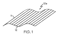
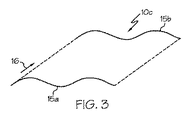
図1〜3は柱面の例を示す図である。図1は、曲線12を通る一連の平行線11によって画成される、例示的な柱面10aを示す図である。図2は、準線14として知られている曲線に沿って、直線13を移動させることによって画成することができる、別の例示的な柱面10bを示す図である。更に別の例において、図3は、開始準線15aが終了準線15bと平行になるように、開始準線15aを方向16に投影することによって画成することができる、柱面10cを示す図である。本明細書が提供する方法を用いて、実質的に柱面を成す鏡面反射面の形状を決定することができる。例えば、柱面の数学的又は理論的な特徴づけを満足又は僅かにずれた表面の形状を決定することができる。1つの実施例において、実質的に柱面を成す鏡面反射面が、素材のリボン、又は素材のリボンから分割された素材板等の、素材板の主面を含むことができる。例えば、実質的に柱面を成す鏡面反射面は、ガラスのリボン、又はガラスのリボンから分割されたガラス板等の、ガラス板の主面を含むことができる。別の実施例において、実質的に柱面を成す鏡面反射面が、光ファイバ又は他の物体の外周面を含むことができる。
1-3 is a figure which shows the example of a column surface. FIG. 1 is a diagram illustrating an exemplary column surface 10 a defined by a series of parallel lines 11 passing through a
物体が実質的に柱面を成す鏡面反射面を有する場合、本方法を用いて実質的に柱面を成す鏡面反射面の形状だけでなく、実質的に柱面を成す鏡面反射面を有する物体の形状も決定することができる。以下、説明のために、実質的に柱面を成す鏡面反射面と言った場合、かかる表面は、遊離した表面又は物体の表面として存在することができると理解されたい。前述のように、本明細書に記載の方法を用いて、かかる表面及び/又はかかる表面を有する物体の形状を決定することができる。 When the object has a specular reflection surface that substantially forms a column surface, not only the shape of the mirror reflection surface that substantially forms a column surface but also a mirror reflection surface that substantially forms a column surface using the present method. The shape of can also be determined. Hereinafter, for purposes of explanation, when referring to a substantially specular reflective surface, it should be understood that such a surface can exist as a free surface or a surface of an object. As described above, the methods described herein can be used to determine the shape of such surfaces and / or objects having such surfaces.
本方法は、校正データを取得するステップを有している。校正データは、データを直接又は間接的にコンピュータにコーディングする、検出器を用いてデータを観察する、センサを用いてデータを測定する、又は校正データを抽出することができるデータを包含する画像を捕捉することを含む、様々な方法で取得することができる。校正データの例には、本方法において、又は本方法によって用いられる、システム、構成要素、又は構造体のいずれかの特性又は複数の特性を表わす座標又は他の情報が含まれる。例えば、校正データは、カメラ、レンズ、又は焦点等のシステムの構成要素の空間的位置、鏡面反射面に関する情報、対象構造体及びその特徴、又はその他任意のパラメータ、初期状態、又はそれに関連するデータを含むことができる。別の実施例において、校正データは、様々なシステム構成要素、構造体、及び変数間の空間的位置又は関係を決定及び規定するために使用できる、基準点又は座標を含むことができる。例えば、校正データは、変換マトリックス又は他の数学的計算により、実空間における三次元座標から二次元の座標に変換することができる。更に別の実施例において、校正データを操作、結合、分析、又は処理して、校正データに対し更に分析、操作、及び/又は計算を行うことができる。 The method includes obtaining calibration data. Calibration data is an image containing data that can be coded directly or indirectly into a computer, observed with a detector, measured with a sensor, or extracted from calibration data. It can be obtained in a variety of ways, including capturing. Examples of calibration data include coordinates or other information representing any characteristic or characteristics of the system, component, or structure used in or by the method. For example, calibration data may include spatial positions of system components such as cameras, lenses, or focal points, information about specular reflection surfaces, target structures and their characteristics, or any other parameters, initial conditions, or data related thereto. Can be included. In another example, the calibration data can include reference points or coordinates that can be used to determine and define a spatial location or relationship between various system components, structures, and variables. For example, calibration data can be transformed from three-dimensional coordinates in real space to two-dimensional coordinates by a transformation matrix or other mathematical calculation. In yet another embodiment, the calibration data can be manipulated, combined, analyzed, or processed to further analyze, manipulate, and / or calculate the calibration data.
本方法は、対象構造体に関する対象データを取得するステップを更に有している。対象データは、データを直接又は間接的にコンピュータにコーディングする、検出器を用いてデータを観察する、センサを用いてデータを測定する、又は対象データを抽出することができるデータを包含する画像を捕捉することを含む、様々な方法で取得することができる。対象データの例には、対象構造体に関連する空間的位置又はその他の基準特性及び/又はそれに関連する特徴を表す座標、及び対象構造体に関連する任意のその他の情報がある。例えば、対象データは、任意の数の特性又は対象構造体及び/又は対象構造体に関連する特徴と様々なシステム構成要素、構造体、及び変数との関係を決定及び規定するために使用できる基準点を含むことができる。更に、これらの基準点は、変換マトリックス又は他の数学的計算により、実空間における三次元の座標から、二次元の座標に変換することができる。更に別の実施例において、対象データを操作、結合、分析、又は処理して、対象データに対し更に分析、操作、及び/又は計算を行うことができる。 The method further comprises the step of obtaining target data relating to the target structure. Target data is an image that contains data that can be coded directly or indirectly into a computer, observed with a detector, measured with a sensor, or extracted from the target data. It can be obtained in a variety of ways, including capturing. Examples of target data include spatial positions or other reference characteristics associated with the target structure and / or coordinates representing features associated therewith and any other information associated with the target structure. For example, the target data can be used to determine and define the relationship between any number of characteristics or target structures and / or features associated with the target structures and various system components, structures, and variables. Can contain points. Furthermore, these reference points can be transformed from three-dimensional coordinates in real space to two-dimensional coordinates by means of a transformation matrix or other mathematical calculations. In yet another embodiment, the subject data can be manipulated, combined, analyzed, or processed to further analyze, manipulate, and / or calculate the subject data.
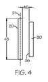
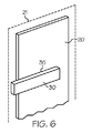
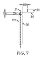
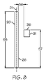
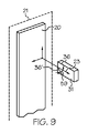
図4〜6に示すように、鏡面反射面20は、平面21に沿って延びることができ、対象構造体30のフィーチャー35を平面21に対して実質的に平行とすることができる。別の実施例において、図7〜9に示すように、鏡面反射面20は、平面21に沿って延びることができ、対象構造体31のフィーチャー36を平面21に対して実質的に垂直とすることができる。対象構造体は、構造体に関連する複数の特徴又は特性のいずれかを含む、任意の1つ又は複数の配列、形状、構造、又は大きさを有することができる。対象構造体は、様々な材料のいずれかで構成することができる。1つの実施例において、対象構造体は、様々な環境における使用に対し望ましい特性を有する、1つ又は複数の材料から構成することができる。更に別の実施例において、光源によって、対象構造体を独立照明又は従属照明することができる。更に別の実施例において、例えば、構造体が何時如何なる時でも、自動又は手動で変更、操作、又は制御できる特徴又は特性を有することができるという点で、対象構造体は動的であり得る。
As shown in FIGS. 4 to 6, the
対象構造体30のフィーチャー35が、鏡面反射面20に対して実質的に平行である、図4〜6に示す実施例において、対象構造体のフィーチャー35は、鏡面反射面20の幅45に沿って、且つ鏡面反射面20から距離46離隔し、鏡面反射面20に対して実質的に平行に延びることができる。対象構造体30の実施的に平行なフィーチャー35は、鏡面反射面20の高さ48に沿った高さ位置47に位置することもできる。
In the embodiment shown in FIGS. 4-6, where the
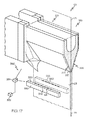
図7〜9の実施例に示すように、対象構造体31のフィーチャー36は、鏡面反射面のエッジ24から距離54離隔し、且つ鏡面反射面20の面26から距離56離隔して、鏡面反射面20に対して実質的に垂直に延びることができる。対象構造体31の実質的に垂直なフィーチャー36は、鏡面反射面20の高さ58に沿った高さ位置57に位置することもできる。更に別の実施例において、対象構造体31の実質的に垂直なフィーチャー36’は、鏡面反射面20の面法線23に対し、角度59を成すことができる。
As shown in the embodiment of FIGS. 7-9, the
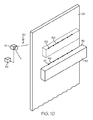
図10に示すように、本方法は、対象データ41から、対象構造体30のフィーチャー35を表す、対象線40を規定するステップを更に有している。対象構造体30のフィーチャー35は、対象構造体30の任意の特徴又は特性であってよい。1つの実施例において、対象構造体のフィーチャー35は、対象構造体30のエッジであってよい。例えば、対象構造体30が、図10に示すように、幾何学形状である場合、対象構造体30のフィーチャー35は、幾何学形状のエッジであってよい。対象構造体30のフィーチャー35は、対象構造体の任意の場所に存在することができ、鏡面反射面20に対し、様々な角度及び/又は様々な方向に延びることができる。
As shown in FIG. 10, the method further includes the step of defining a target line 40 representing the
例えば、周知のエッジ検出技法を用いて、対象構造体のエッジ又は他の特徴又は特性に対応するデータ点を数学的に規定することができる。様々な数学的手法が周知であり、それ等を用いて、対象データから対象線を規定することができる。1つの実施例において、本ステップは、対象データからの複数のデータ点であって、対象構造体のフィーチャーに関連付けることができるデータ点に関する回帰分析を行うことを含むことができる。任意の回帰分析法又は他の数学的手法を用いて、これ等のデータ点から、対象線を決定することができる。 For example, well-known edge detection techniques can be used to mathematically define data points corresponding to edges or other features or characteristics of the target structure. Various mathematical techniques are well known and can be used to define a target line from target data. In one embodiment, this step can include performing a regression analysis on a plurality of data points from the target data that can be associated with features of the target structure. The target line can be determined from these data points using any regression analysis method or other mathematical techniques.
図10に示すように、本方法は、鏡面反射面20における、対象構造体30の反射像50を捕捉するステップを更に有している。反射像50は、カメラ又はその他の画像やビデオ記録装置等の、画像捕捉装置51を用いて捕捉することができる。捕捉したのち、反射像50の分析を行うことができ、又はコンピュータ52に転送することによって、画像に含まれるデータの抽出、処理、及び/若しくは分析を行うことができる。
As shown in FIG. 10, the method further includes the step of capturing a
更に図10に示すように、本方法は、反射像50から、反射データ55を取得するステップを更に有している。反射データ55は、反射像50を抽出、処理、及び/又は分析して反射データ55を取得することを含む、様々な方法で取得することができる。反射データ55の例には、対象構造体の反射像50に関連する空間的位置又はその他の基準特性、及び/又はそれに関連する反射フィーチャーを表す座標、及び反射像50に関連する任意のその他の情報がある。例えば、反射データ55は、任意の数の特性又は対象構造体の反射像50及び/又はそれに関連する反射フィーチャーと様々なシステム構成要素、構造体、及び変数との関係を決定及び規定するために使用できる基準点を含むことができる。更に、これらの基準点は、変換マトリックス又は他の数学的計算により、実空間における三次元の座標から、二次元の座標に変換することができる。更に別の実施例において、反射データ55を操作、結合、分析、又は処理して、反射データに対し、更に分析、操作、及び/又は計算を行うことができる。
Further, as shown in FIG. 10, the method further includes the step of acquiring
更に図10に示すように、本方法は、反射データ55から、対象構造体30のフィーチャー35の反射を表す反射線60を規定するステップを更に有している。前述のように、対象構造体30のフィーチャー35は、対象構造体30の任意の特徴又は特性であってよい。従って、対象構造体30のフィーチャー35の反射は、対象構造体30の任意の特徴又は特性の対応する反射であってよい。前述のように、1つの実施例において、対象構造体30のフィーチャー35は、対象構造体30のエッジであってよい。従って、対象構造体のフィーチャーの反射は、反射像50から抽出された反射データ55から規定される、反射線60によって表わされる、対象構造体のエッジの対応する反射であってよい。例えば、対象構造体が幾何学形状である場合、対象構造体のフィーチャーは、幾何学形状のエッジであってよく、フィーチャーの反射は、幾何学形状のエッジの対応する反射であってよい。
As further shown in FIG. 10, the method further comprises defining a reflection line 60 representing the reflection of the
例えば、周知のエッジ検出技法を用いて、対象構造体のエッジ又は他の特徴若しくは特性に対応するデータ点を数学的に規定することができる。様々な数学的手法が周知であり、それ等を用いて、反射データから反射線を規定することができる。1つの実施例において、本ステップは、反射データからの複数のデータ点であって、対象構造体のフィーチャーの反射に関連付けることができるデータ点に関する回帰分析を行うことを含んでいる。任意の回帰分析法又は他の数学的手法を用いて、これ等のデータ点から、対象反射線を決定することができる。 For example, well-known edge detection techniques can be used to mathematically define data points corresponding to the edges or other features or characteristics of the target structure. Various mathematical techniques are well known and can be used to define reflected lines from reflection data. In one embodiment, this step includes performing a regression analysis on a plurality of data points from the reflection data that can be associated with reflections of features of the target structure. From these data points, the target reflection can be determined using any regression analysis method or other mathematical techniques.
本方法は、対象線40と反射線60との対応関係を決定するステップを更に有している。対応関係は、例えば、対象線40のすべて又は一部と、反射線60のすべて又は一部との比較、相関、又はその他任意の1つ又は複数の関係を含むことができる。例えば、対象線40を分析することができる。別の実施例において、反射線60を分析することができる。更に別の実施例において、対象線40及び反射線60を分析することができる。対応関係は、コンピュータ又は手動処理、数学的計算、又はその他の方法による演算を含む、様々な方法のうちの任意の方法で決定することができる。1つの実施例において、対応関係は、対象構造体30の対象データ41からの対象線40と比較した、反射像50の反射データ55からの反射線60の歪みの決定を含むことができる。
The method further includes the step of determining the correspondence between the target line 40 and the reflection line 60. The correspondence relationship may include, for example, a comparison, correlation, or any other one or more relationships between all or part of the target line 40 and all or part of the reflection line 60. For example, the target line 40 can be analyzed. In another example, the reflected line 60 can be analyzed. In yet another embodiment, the target line 40 and the reflection line 60 can be analyzed. Correspondence can be determined in any of a variety of ways, including computation by computer or manual processing, mathematical calculations, or other methods. In one example, the correspondence can include determining the distortion of the reflection line 60 from the
本方法は、対応関係及び校正データを用いて鏡面反射面20の形状を決定するステップを更に有している。1つの実施例において、対応関係の全部または一部を使用することができる。別の実施例において、校正データの全部または一部を使用することができる。更に別の実施例において、対応関係の全部または一部を使用することができると共に、校正データの全部または一部を使用することができる。例えば、本ステップは、形状回復アルゴリズムの実行を含むことができる。形状回復アルゴリズムは、任意のデータを用いて、鏡面反射面20の形状を決定することができる。例えば、鏡面反射面20の形状は、復元、回復、逆算、あるいは、対応関係及び校正データに基づいて、対象構造体30の捕捉反射像50を生成することになる、鏡面反射面の輪郭又はプロファイルを推定することによって決定することができる。
The method further includes determining the shape of the
図11に示すように、1つの実施例において、形状によって、鏡面反射面20の断面プロファイル70を近似することができる。断面プロファイル70は、例えば、鏡面反射面20と交差する平面75における、鏡面反射面の断面であってよい。別の実施例において、鏡面反射面を有する物体が薄く、長さ及び幅より実質的に小さい厚さを有する場合、断面プロファイル70は、鏡面反射面と交差する平面75に存在する線又は曲線71として近似することができる。更に別の実施例において、本方法は、鏡面反射面20の複数の形状72を決定するステップを更に有することができる。例えば、複数の形状72の各々の形状73によって、鏡面反射面20の断面プロファイル70又は曲線71を近似することができる。
As shown in FIG. 11, in one embodiment, the cross-sectional profile 70 of the
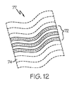
図12に示す、更に別の実施例において、本方法は、複数の形状72に基づいて、鏡面反射面20の表面プロファイル74を近似するステップを更に有することができる。表面プロファイル74は、例えば、複数の形状72を、それらの間の関係に基づいて、空間的に順序付けして配置することによって決定することができる。1つの実施例において、複数の形状72をデジタル的に組み立てることにより、鏡面反射面20の全表面プロファイル77を近似することができる、レンダリングされた画像を生成することができる。例えば、鏡面反射面が、素材板の主面を含む場合、形状によって、素材板の一部又は全部の実際の形状を近似又はシミュレートすることができる。
In yet another embodiment, shown in FIG. 12, the method may further include approximating the
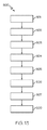
本方法のステップのいずれも、同じ又は異なる任意の時間周波数で実行することができる。例えば、図13に示すように、校正データを取得するステップ501、対象データを取得するステップ502、対象データから対象線を規定するステップ503、反射像を捕捉するステップ504、反射データを取得するステップ505、反射線を規定するステップ506、対応関係を決定するステップ507、並びに対応関係及び校正データを用いて、鏡面反射面の形状を決定するステップ508を有する方法ステップ500は、同じ又は異なる任意の時間周波数で実行することができる。1つの実施例において、いずれのステップも、少なくとも1秒に1回の割合で実行することができる。別の実施例において、いずれのステップも、時間周波数の周期がゼロに近づくような速度で、繰り返すことができる。例えば、いずれのステップも、時間的に実質的に連続する速度で実行することができる。更に別の実施例において、いずれのステップも、任意の数の変数によって規定される速度で実行することができる。更に、いずれのステップも1回実行することができる。1つの実施例において、1つ以上のステップを1回実行することができる一方、他のステップを複数回実行することができる。
Any of the method steps can be performed at any time frequency, the same or different. For example, as shown in FIG. 13,
校正データを取得するステップ501、対象データを取得するステップ502、対象データから対象線を規定するステップ503、反射像を捕捉するステップ504、反射データを取得するステップ505、反射線を規定するステップ506、対応関係を決定するステップ507、並びに対応関係及び校正データを用いて、鏡面反射面の形状を決定するステップ508を有する、図13に示す方法ステップ500のいずれも、様々なコンピュータ、数値、数学、線形、非線形、科学、デジタル、電子、又は他の手法を使用することができる。更に、任意の構成、推定、操作、又は計算を一緒に又は単独で、本明細書に記載の方法のステップのいずれに対しても実行することができる。
Step 501 for obtaining calibration data,
例えば、捕捉又は取得した画像を、画像分析を用いて分析し、画像に含まれているデータを画像から抽出することができる。別の実施例において、対象構造体の特定の領域、鏡面反射面の特定の領域、及び/又は鏡面反射面における対象構造体の反射像を表すことができる関心領域を規定することができる。関心領域はユーザによって規定することができ、直接又は間接的にコンピュータにプログラムするか、又はソフトウェアルーチン又はその他のプロシージャーを用いて、自動的に決定することができる。更に別の実施例において、導関数畳み込みを用いて、対象構造体の名目上のフィーチャーに垂直な方向の変化を強調することができる。導関数畳み込みは、例えば、データ点間のデータ点の値の変化率を示すことができる。更に別の実施例において、導関数畳み込みを用いて、対象データを表す対象線の大まかな近似、及び反射データを表す反射線の位置を特定することができる。この処理によって、例えば、対象構造体のフィーチャーに垂直なデータ点の値に対する最大の変化を表す、極大絶対値の点が特定される。更に別の実施例において、データ点にフィルタをかけて、対象構造体のフィーチャーの一般的な方向又は方向の傾向から外れ過ぎている点を除去又は外れ値と見なすことができる。更に別の実施例において、サブピクセル補間を用いて、最大の導関数の極大絶対値を有するデータ点を決定することができる。このことから、このデータ点の各々の側の少なくとも2つの点を用いて、多項式をデータ点に当てはめることができ、実際のピーク位置を決定することができる。例えば、対象構造体のフィーチャー、又は鏡面反射面における、フィーチャーに対応する反射に関連付けることができる、取得した各々のデータ点に対し、この補間を実行することができる。更に別の実施例において、統合的方法論を用いることができ、積分点を規定することができる。鏡面反射面の多数の形状によって、同じ反射がもたらされる可能性があるので、積分点を用いて、鏡面反射面全体にわたる統合の開始点を確立することができる。更に別の実施例において、微分方程式回復法の初期条件を規定することができる。更に別の実施例において、三次元点処理法を用いて、校正データ、対象データ、又は反射データのデータ点に対応する三次元の座標を、対象構造体の位置、及びそれに対応する反射を規定することができる、二次元の座標に変換することができる。別の実施例において、データのフィルタリングを実行することができ、校正データ、対象データ、又は反射データが処理され、すべての外れ値が除去される。1つの実施例において、このフィルタリング処理が、例えば、対象構造体のフィーチャー、及び/又は鏡面反射面における、対応する反射に関連付けることができるデータ点に、多項式線を当てはめることを含んでいる。別の実施例において、当てはめた線から所定距離の範囲外のすべてのデータ点が、外れ値として特定される。外れ値はデータセットから除去することも、データセットに保持することもできる。更に別の実施例において、線を当てはめる処理、外れ値を特定する処理、及び外れ値をデータセットから除去又は保持する処理は、同じ又は異なる多項式フィッティング及び/又は同じ又は異なる外れ値棄却限界を用いて、任意の回数繰り返すことができる。 For example, the captured or acquired image can be analyzed using image analysis, and the data contained in the image can be extracted from the image. In another example, a specific region of the target structure, a specific region of the specular reflection surface, and / or a region of interest that can represent a reflected image of the target structure at the specular reflection surface can be defined. The region of interest can be defined by the user, programmed directly or indirectly into a computer, or automatically determined using software routines or other procedures. In yet another embodiment, derivative convolution can be used to emphasize changes in the direction perpendicular to the nominal features of the target structure. Derivative convolution can indicate, for example, the rate of change of the value of a data point between data points. In yet another embodiment, derivative convolution can be used to determine a rough approximation of the object line representing the object data and the position of the reflection line representing the reflection data. By this processing, for example, a point having a maximum absolute value representing the maximum change with respect to the value of the data point perpendicular to the feature of the target structure is specified. In yet another embodiment, data points can be filtered to remove or consider points that are too far from the general direction or orientation trend of the feature of interest structure. In yet another embodiment, subpixel interpolation may be used to determine the data point having the maximum derivative maximum absolute value. From this, using at least two points on each side of this data point, a polynomial can be fitted to the data point and the actual peak position can be determined. For example, this interpolation can be performed on each acquired data point that can be associated with a feature corresponding to the feature in the target structure or specular reflection surface. In yet another embodiment, an integrated methodology can be used and integration points can be defined. Since multiple shapes of specular reflective surfaces can result in the same reflection, integration points can be used to establish a starting point of integration across the specular reflective surface. In yet another embodiment, initial conditions for the differential equation recovery method can be defined. In yet another embodiment, three-dimensional point processing is used to define the three-dimensional coordinates corresponding to the data points of the calibration data, target data, or reflection data, the position of the target structure, and the corresponding reflection. Can be converted to two-dimensional coordinates. In another embodiment, data filtering can be performed, and calibration data, object data, or reflection data is processed to remove all outliers. In one embodiment, the filtering process includes fitting a polynomial line to data points that can be associated with features of the target structure and / or corresponding reflections at specular reflective surfaces, for example. In another embodiment, all data points outside a predetermined distance from the fitted line are identified as outliers. Outliers can be removed from the data set or retained in the data set. In yet another embodiment, the process of fitting lines, identifying outliers, and removing or retaining outliers from a data set uses the same or different polynomial fittings and / or the same or different outlier rejection limits. Can be repeated any number of times.
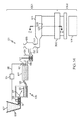
本開示の別の態様は、図14に示すように、多量の溶融ガラス121から延伸された、ガラスリボン103の形状を決定する方法を含んでいる。製造された後、ガラスリボン103は、様々な用途に用いることができるガラス板104に分離することができる。例えば、ガラスリボン103から製造されたガラス板104は、表示用途等に用いることができる。具体的な例において、ガラス板104は、液晶ディスプレイ(LCD)、電気泳動ディスプレイ(EPD)、有機発光ダイオードディスプレイ(OLED)、プラズマディスプレイパネル(PDP)、又はその他の表示装置の製造に用いることができる。
Another aspect of the present disclosure includes a method for determining the shape of a
ガラスリボンは、本開示に従ってガラスリボンを製造するための、スロットドロー、フロート、ダウンドロー、フュージョンダウンドロー、又はアップドロー等の、様々な装置によって製造することができる。各々の装置は、バッチ材料を多量の溶融ガラスに溶融するように構成された、溶融容器を有することができる。各々の装置は、少なくとも、溶融容器の下流に配置された第1の調整ステーション、及び第1の調整ステーションの下流に配置された第2の調整ステーションを更に有している。 The glass ribbon can be produced by a variety of devices, such as slot draw, float, down draw, fusion down draw, or up draw, for producing a glass ribbon in accordance with the present disclosure. Each device can have a melting vessel configured to melt the batch material into a quantity of molten glass. Each apparatus further includes at least a first adjustment station disposed downstream of the melting vessel and a second adjustment station disposed downstream of the first adjustment station.
図14は、本開示に従ってガラスリボンを製造するための、単なる1つの例示的な装置の概略図であって、本装置は、後にガラス板104に加工される、ガラスリボン103を溶融延伸するためのフュージョンドロー装置101を備えている。フュージョンドロー装置101は、原料貯蔵槽109からバッチ材料107を受け取るように構成された溶融容器105を有することができる。バッチ材料107は、モータ113を動力源とするバッチ供給装置111によって導入することができる。モータ113を駆動するための、任意のコントローラ115を構成して、矢印117で示すように、所望の量のバッチ材料107を溶融容器105に導入することができる。ガラス材料プローブ119を用いて、立て管123内のガラス融液121のレベルを測定し、通信線125を介して、測定情報をコントローラ115に通信することができる。
FIG. 14 is a schematic diagram of just one exemplary apparatus for manufacturing a glass ribbon in accordance with the present disclosure, which apparatus for melt drawing a
フュージョンドロー装置101は、溶融容器105の下流に位置し、第1の接続管129を介して溶融容器105に接続された、清澄容器127(例えば、清澄管)等の第1の調整ステーションも有することができる。一部の実施例において、接続管129を介し、第1の溶融容器105から清澄容器127に、ガラス融液を重力供給することができる。例えば、重力はガラス融液に作用して、溶融容器105から清澄容器127まで、第1の接続管129の内部通路を強制通過させることができる。清澄容器127内において、様々な手法によって、ガラス融液から気泡を除去することができる。
The
フュージョンドロー装置は、清澄容器127の下流に位置することができる、撹拌容器131(例えば、撹拌室)等の第2の調整ステーションも有することができる。撹拌容器131を用いて、均一なガラス融液組成を提供することができ、撹拌容器を用いなければ、清澄容器を出た清澄化されたガラス融液に存在し得る不均一な筋を抑制又は除去することができる。図示のように、溶清澄容器127は、第2の接続管135を介して、撹拌容器131に接続することができる。一部の実施例において、第2の接続管135を介し、清澄容器127から撹拌容器131に、ガラス融液を重力供給することができる。例えば、重力はガラス融液に作用して、溶融清澄容器127から撹拌容器131まで、第2の接続管135の内部通路を強制通過させることができる。
The fusion draw device can also have a second conditioning station, such as a stirring vessel 131 (eg, a stirring chamber), which can be located downstream of the fining
フュージョンドロー装置は、撹拌容器131の下流に位置することができる、供給容器133(例えば、ボウル)等の別の調整ステーションを更に有することができる。供給容器133は、成形装置に供給されるガラスを調整することができる。例えば、供給容器133は、ガラス融液を調整して、常に一定量のガラス融液を、成形装置に供給するためのアキュムレータ及び/又は流量調整器として機能することができる。図示のように、撹拌容器131は、第3の接続管137を介して、供給容器133に接続することができる。一部の実施例において、第3の接続管1375を介し、撹拌容器131から供給容器133に、ガラス融液を重力供給することができる。例えば、重力はガラス融液に作用して、撹拌容器131から供給容器133まで、第3の接続管137の内部通路を強制通過させることができる。
The fusion draw apparatus can further comprise another conditioning station, such as a supply vessel 133 (eg, a bowl), which can be located downstream of the agitation vessel 131. The
更に図示するように、下降管139を配置して、供給容器133から成形容器143の注入口141に、ガラス融液121を供給することができる。図示のように、溶融容器105、清澄容器127、撹拌容器131、供給容器133、及び成形容器143は、フュージョンドロー装置101に沿って連続配置することができる、ガラス融液調整ステーションの例である。
Further, as shown in the drawing, the
溶融容器105は、概して、耐火(例えば、セラミック)煉瓦等の耐火材料から成っている。フュージョンドロー装置101は、概して、白金、又は白金−ロジウム、白金−イリジウム、及びこれ等の組合せ等の白金含有金属から成る構成要素を更に有することができるが、これ等の構成要素はモリブデン、パラジウム、レニウム、タンタル、チタン、タングステン、ルテニウム、オスミウム、ジルコニウム、これ等の合金、及び/又は二酸化ジルコニウム等の耐火材料から成ることもできる。白金を含有する構成要素は、第1の接続管129、清澄容器127(例えば、清澄管)、第2の接続管135、立て管123、撹拌容器131(例えば、撹拌室)、第3の接続管137、供給容器133(例えば、ボウル)、下降管139、及び注入口141のうちの1つ以上を含むことができる。成形容器143も耐火材料から成り、ガラスリボン103を成形するように設計されている。
The
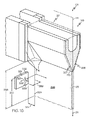
図15は、図14のフュージョンドロー装置101の2−2線斜視断面図である。図示のように、成形容器143は、対向する端部間に延びる一対の下方に傾斜した成形面部分207、209を備えた成形ウェッジ201を有している。一対の下方に傾斜した成形面部分207、209は延伸方向211に沿って合流し、根底部213を形成している。延伸面215が、根底部213を通して延び、延伸面215に沿って、ガラスリボン103を、延伸方向211、例えば下流方向、に延伸することができる。図示のように、延伸面215は、根底部213を二等分することができるが、延伸面215は、根底部213に対し別の向きに延びることもできる。
15 is a perspective sectional view taken along line 2-2 of the
図14に示すように、フュージョンドロー装置101は、多量の溶融ガラス121から延伸された、ガラスリボン103の形状を決定するための方法を実行するシステム300を有することができる。また、本方法を実行して、光ファイバ及び他のガラス要素を含む、鏡面反射特性を有する他の物体の形状を決定することもできる。多量の溶融ガラス121から延伸された、ガラスリボン103の形状を決定するための方法について、以下説明する。1つの実施例において、ガラスリボン103を連続して延伸方向211に移動させることができる。別の実施例において、ガラスリボンの形状を用いて、ガラス成形装置101の上流のパラメータ301を制御することができる。更に別の実施例において、ガラスリボンの形状を用いて、下流工程302のパラメータを制御することができる。更に別の実施例において、ガラスリボンの形状を用いて、ガラス成形装置101の上流パラメータ301及び下流工程302のパラメータを制御することができる。更に別の実施例において、ガラスリボンの形状を用いて、ガラスリボンの属性を決定することができ、属性に基づいてガラスリボンの品質を分類することができる。
As shown in FIG. 14, the
例えば、属性は成形処理中にガラスリボンに生じ得る、内包物、傷、又はその他のあらゆる欠陥若しくは凹凸等の形状異常を含むことができる。このような異常によって、ガラスリボンが要求仕様特性又はパラメータから外れる可能性があり、ガラスリボン又はガラス板が拒絶又は別の用途に特定される可能性がある。別の実施例において、属性は、ガラスリボンの運動、又はガラスリボンの形状若しくは組成変化を証するものであってよい。ガラスリボンの様々な場所、及び成形及び/又は処理工程全体を通した様々な時間に、これ等の属性を監視することによって、成形及び/又は処理工程を制御することができ、様々なガラス成形及び/又は処理パラメータを調整又は一致させることができる。これ等の属性は定期的、繰り返し、又は連続的に監視することができ、例えば、これ等の属性を用いて、プロット、グラフ、チャート、データベース、又は数値データ等の様々な出力情報を生成することができる。別の実施例において、ガラスリボンから切断された特定のガラス板に、属性を関連付けることができる。特性が要求仕様から外れている場合、当該特定のガラス板は、その後破棄することができ、必要があれば更に処理するか、又は属性に基づいて、特定の用途用として特定、若しくは特定の場所へ割り振られる。更に別の実施例において、属性を用いて、ガラスリボンの品質及び/又はガラス板の品質が望ましい品質又は特性となる、安定した生産に対応する動作条件を決定することができる。更に別の実施例において、ガラスリボンの品質及び/又はガラス板の品質が、望ましい品質又は特性を示すガラスリボン又はガラス板の品質と異なる、望ましくない生産に対応する動作条件を決定することができる。更に別の実施例において、ガラス成形装置の特定の構成要素、システム、又は機能が適切又は不適切に機能しているとき、属性を用いて、コンピュータ又はユーザに通知することができる。例えば、本明細書に開示した方法によって算出される形状から決定される、ガラスリボンの特定の属性に基づいて、システムの特定の要素が交換又は修理を要する事例、又は溶融ガラスを製造するための様々な入力を調整して、例えば、ガラスリボン及び/又はガラス板の品質を向上させることができる事例を決定することができる。更に、属性間の相関を決定することができる。かかる相関はある期間のわたり決定することができ、本方法によって決定又は他の制御から供給されるガラス成形工程、ガラスリボン、及び/又はガラス板に関わる、種々の多くのパラメータのいずれも含むことができる。更に別の実施例において、ガラスリボン及び/又はガラス板の形状を用いて、ガラス成形、ガラスリボンの特性、及びガラス板の特性の変化を把握することができる。形状を監視及び/又は分析して、例えば、本明細書に記載の方法に関連する品質、効率、又はその他の特徴、パラメータ、若しくは態様を向上させることができる。 For example, attributes can include shape abnormalities such as inclusions, scratches, or any other defects or irregularities that can occur in the glass ribbon during the molding process. Such anomalies can cause the glass ribbon to deviate from the required specification characteristics or parameters, and the glass ribbon or glass plate can be rejected or otherwise specified. In another example, the attribute may be evidence of glass ribbon movement or glass ribbon shape or composition change. By monitoring these attributes at various locations on the glass ribbon and at various times throughout the forming and / or processing process, the forming and / or processing process can be controlled, and various glass forming processes can be performed. And / or processing parameters can be adjusted or matched. These attributes can be monitored periodically, repeatedly, or continuously, for example, using these attributes to generate various output information such as plots, graphs, charts, databases, or numerical data. be able to. In another example, an attribute can be associated with a particular glass plate cut from a glass ribbon. If the properties deviate from the required specifications, the specific glass plate can then be discarded and further processed if necessary, or specified for a specific application or specific location based on attributes Allocated to In yet another embodiment, the attributes can be used to determine operating conditions corresponding to stable production where the quality of the glass ribbon and / or the quality of the glass sheet is a desirable quality or characteristic. In yet another embodiment, operating conditions corresponding to undesired production can be determined in which the quality of the glass ribbon and / or the quality of the glass plate is different from the quality of the glass ribbon or glass plate exhibiting the desired quality or characteristics. . In yet another embodiment, attributes may be used to notify a computer or user when certain components, systems, or functions of a glass forming apparatus are functioning properly or inappropriately. For example, when a particular element of the system requires replacement or repair based on specific attributes of the glass ribbon determined from the shape calculated by the method disclosed herein, or for producing molten glass Various inputs can be adjusted to determine, for example, cases where the quality of the glass ribbon and / or glass plate can be improved. Furthermore, correlations between attributes can be determined. Such a correlation can be determined over a period of time and includes any of a number of different parameters related to the glass forming process, glass ribbon, and / or glass sheet determined by the method or supplied from other controls. Can do. In yet another embodiment, the shape of the glass ribbon and / or glass plate can be used to ascertain changes in glass forming, glass ribbon properties, and glass plate properties. The shape can be monitored and / or analyzed to improve, for example, quality, efficiency, or other features, parameters, or aspects associated with the methods described herein.
本方法は、校正データを取得する方法を有している。前述のように、校正データは、データを直接又は間接的にコンピュータにコーディングする、検出器を用いてデータを観察する、センサを用いてデータを測定する、又は校正データを抽出することができるデータを包含する画像を捕捉することを含む、様々な方法で取得することができる。校正データの例には、本方法において、又は本方法によって用いられる、システム、構成要素、又は構造体のいずれかの特性又は複数の特性を表わす座標又は他の情報が含まれる。例えば、校正データは、カメラ、レンズ、又は焦点等のシステムの構成要素の空間的位置、ガラスリボンに関する情報、対象構造体及びその特徴、又はその他任意のパラメータ、初期状態、又はそれに関連するデータを含むことができる。別の実施例において、校正データは、様々なシステム構成要素、構造体、及び変数間の位置又は関係を決定、及び規定するために使用できる基準点又は座標を含むことができる。例えば、校正データは、変換マトリックス又は他の数学的計算により、実空間における三次元座標から二次元の座標に変換することができる。更に別の実施例において、校正データを操作、結合、分析、又は処理して、校正データに対し更に分析、操作、及び/又は計算を行うことができる。 This method has a method of acquiring calibration data. As described above, calibration data is data that can be coded directly or indirectly into a computer, observed data using a detector, measured data using a sensor, or extracted calibration data. Can be obtained in a variety of ways, including capturing images containing Examples of calibration data include coordinates or other information representing any characteristic or characteristics of the system, component, or structure used in or by the method. For example, calibration data may include spatial locations of system components such as cameras, lenses, or focal points, information about glass ribbons, target structures and their features, or any other parameters, initial conditions, or related data. Can be included. In another example, calibration data can include reference points or coordinates that can be used to determine and define positions or relationships between various system components, structures, and variables. For example, calibration data can be transformed from three-dimensional coordinates in real space to two-dimensional coordinates by a transformation matrix or other mathematical calculation. In yet another embodiment, the calibration data can be manipulated, combined, analyzed, or processed to further analyze, manipulate, and / or calculate the calibration data.
本方法は、対象構造体に関する対象データを取得するステップを更に有している。前述のように、対象データは、データを直接又は間接的にコンピュータにコーディングする、検出器を用いてデータを観察する、センサを用いてデータを測定する、又は対象データを抽出することができるデータを包含する画像を捕捉することを含む、様々な方法で取得することができる。対象データの例には、対象構造体に関連する空間的位置又はその他の基準特性及び/又はそれに関連する特徴を表す座標、及び対象構造体に関連する任意のその他の情報がある。例えば、対象データは、任意の数の特性又は対象構造体及び/又は対象構造体に関連する特徴と様々なシステム構成要素、構造体、及び変数との関係を決定及び規定するために使用できる基準点を含むことができる。更に、これらの基準点は、変換マトリックス又は他の数学的計算により、実空間における三次元の座標から、二次元の座標に変換することができる。更に別の実施例において、対象データを操作、結合、分析、又は処理して、対象データに対し更に分析、操作、及び/又は計算を行うことができる。1つの実施例において、対象構造体は、対象構造体としての役割を果たすことに加え、ガラス成形及び処理に関する別の機能を果たすことができる、ガラス成形装置101内の既存の構造体であってよい。別の実施例において、対象構造体は、本明細書に記載の方法において、対象構造体として機能させることを唯一の目的として、ガラス成形装置101に導入された専用の構造体であってよい。
The method further comprises the step of obtaining target data relating to the target structure. As mentioned above, the target data is data that can code the data directly or indirectly into a computer, observe the data using a detector, measure the data using a sensor, or extract the target data. Can be obtained in a variety of ways, including capturing images containing Examples of target data include spatial positions or other reference characteristics associated with the target structure and / or coordinates representing features associated therewith and any other information associated with the target structure. For example, the target data can be used to determine and define the relationship between any number of characteristics or target structures and / or features associated with the target structures and various system components, structures, and variables. Can contain points. Furthermore, these reference points can be transformed from three-dimensional coordinates in real space to two-dimensional coordinates by means of a transformation matrix or other mathematical calculations. In yet another embodiment, the subject data can be manipulated, combined, analyzed, or processed to further analyze, manipulate, and / or calculate the subject data. In one embodiment, the target structure is an existing structure in the
図15に示すように、ガラスリボン103は、平面215に沿って延びることがで、対象構造体330のフィーチャー335は、平面215に対して実質的に平行であってよい。図16に示す、別の実施例において、ガラスリボン103は、平面215に沿って延びることがで、対象構造体331のフィーチャー336は、平面215に対して実質的に垂直であってよい。対象構造体330、331は、構造体に関連する複数の特徴又は特性のいずれかを含む、任意の1つ又は複数の配列、形状、構造、又は大きさを有することができる。対象構造体は、様々な環境で使用される、様々な材料のいずれかで構成することができる。例えば、ガラス成形装置101において、対象構造体は、高温環境に耐える適切な材料で構成することができる。更に別の実施例において、光源によって、対象構造体を独立照明又は従属照明することができる。例えば、対象構造体330、331は、フュージョンドロー装置101内に存在することができ、窓又は他の開口部を含めて、対象構造体を照明する光源のビューポートを提供することができる。窓又は他の開口部は、フュージョンドロー装置内に存在している既存の窓若しくは開口部、又は対象構造体を照明する光源のビューポートを提供することを唯一の目的として含められた専用の窓若しくは開口部であってよい。更に別の実施例において、例えば、構造体が何時如何なる時でも、自動又は手動で変更、操作、又は制御できる特徴又は特性を有することができるという点で、対象構造体は動的であり得る。
As shown in FIG. 15, the
対象構造体330のフィーチャー335が、ガラスリボン103に対して実質的に平行である、図15に示す1つの実施例において、対象構造体330のフィーチャー335は、ガラスリボン103の幅345に沿って、且つガラスリボン103から距離346離隔して、ガラスリボンに対して実質的に平行に延びることができる。対象構造体330の実質的に平行なフィーチャー335は、ガラスリボン103の高さ348に沿った高さ位置347に位置することもできる。
In one embodiment shown in FIG. 15 where the
対象構造体331のフィーチャー336が、ガラスリボン103に対して実質的に垂直である、図15に示す1つの実施例において、対象構造体331のフィーチャー336は、ガラスリボンのエッジ324から距離354離隔し、且つガラスリボン103の面326から距離356離隔して、ガラスリボン103に対して実質的に垂直に延びることができる。対象構造体331の実質的に垂直なフィーチャー336は、ガラスリボン103の高さ358に沿った高さ位置357に位置することができる。更に別の実施例において、対象構造体331の実質的に垂直なフィーチャー336’は、ガラスリボン103の面法線323に対し、角度359を成すことができる。
In one embodiment shown in FIG. 15 where the
図17に示すように、本方法は、対象データ341から、対象構造体330のフィーチャー335を表す、対象線340を規定するステップを更に有している。対象構造体330のフィーチャー335は、対象構造体330の任意の特徴又は特性であってよい。1つの実施例において、対象構造体のフィーチャー335は、対象構造体330のエッジであってよい。例えば、対象構造体330が、図17に示すように、幾何学形状である場合、対象構造体のフィーチャー335は、幾何学形状のエッジであってよい。対象構造体330のフィーチャー335は、対象構造体の任意の場所に存在することができ、ガラスリボン103に対し、様々な角度及び/又は様々な方向に延びることができる。
As shown in FIG. 17, the method further includes the step of defining a
前述のように、周知のエッジ検出技法を用いて、対象構造体のエッジ又は他の特徴又は特性に対応するデータ点を数学的に規定することができる。様々な数学的手法が周知であり、それ等を用いて、対象データから対象線を規定することができる。1つの実施例において、本ステップは、対象データからの複数のデータ点であって、対象構造体のフィーチャーに関連付けることができるデータ点に関する回帰分析を行うことを含むことができる。任意の回帰分析法又は他の数学的手法を用いて、これ等のデータ点から、対象線を決定することができる。 As previously mentioned, well-known edge detection techniques can be used to mathematically define data points corresponding to the edges or other features or characteristics of the target structure. Various mathematical techniques are well known and can be used to define a target line from target data. In one embodiment, this step can include performing a regression analysis on a plurality of data points from the target data that can be associated with features of the target structure. The target line can be determined from these data points using any regression analysis method or other mathematical techniques.
図17に示すように、本方法は、ガラスリボン103における、対象構造体330の反射像350を捕捉するステップを更に有している。前述のように、反射像350は、カメラ又はその他の画像やビデオ記録装置等の、画像捕捉装置351を用いて捕捉することができる。捕捉したのち、反射像350の分析を行うことができ、又はコンピュータ352に転送することによって、画像に含まれるデータの抽出、処理、及び/若しくは分析を行うことができる。
As shown in FIG. 17, the method further includes the step of capturing a
図18に示すように、1つ以上の画像捕捉装置351を用いて、1つ以上の対象構造体330の1つ以上の反射像350を捕捉することができる。図18に示す、別の実施例において、ガラスリボン103の様々な場所で、1つ以上の反射像350を捕捉することができる。更に別の実施例において、反射像350は、対象構造体のフィーチャーのいずれか又はすべての反射だけでなく、対象構造体のいずれか又はすべての反射を含むことができる。例えば、カメラ等の画像捕捉装置351が、ガラスリボン103の約半分の幅にわたり、反射像350を捕捉するように、画像捕捉装置351を、ガラスリボン103の脇に配置することができる。別の実施例において、第2のカメラ等の第2の画像捕捉装置351を、第2の画像捕捉装置もガラスリボンの約半分の幅にわたり、反射像を捕捉するように、ガラスリボンの反対側の、第1の画像捕捉装置と同じ又は同様の高さ位置に配置することができる。第1の画像捕捉装置及び第2の画像捕捉装置は、例えば、ガラスリボンの全幅にわたり、対象構造体の反射像を捕捉することができる。更に別の実施例において、ガラスリボンの重複領域を含む反射像を捕捉するように、第1の画像捕捉装置及び第2の画像捕捉装置を構成することができる。重複領域は、例えば、校正又はガラスリボンの同じ空間的位置に対応する多数のデータ点が有益である、他の構成の計算に用いることができる。
As shown in FIG. 18, one or more
更に別の実施例において、ガラスリボン103に関連した、画像捕捉装置又は複数の画像捕捉装置の位置又は角度に基づいて、反射像350の特性又は態様を捕捉することができる。更に別の実施例において、障害物や制約によって、反射像を理想的に捕捉するための位置に、画像捕捉装置を配置できない可能性がある。画像捕捉装置の位置及び/角度を手動又は自動で調整して、かかる障害物又は制約に対応できるようにすると共に、画像捕捉装置を取り外し、フュージョンドロー装置101にアクセスして、装置の検査、清掃、及び修理ができるように、例えば、画像捕捉装置351を、調整可能な機構に取り付けることができる。更に別の実施例において、同じ又は異なる画像捕捉装置を配置して、ガラスリボン103、対象構造体330、331、及びガラス成形装置101若しくは処理ステップにおいて、又はガラス成形装置101若しくは処理ステップによって使用される、他の構成要素の画像を捕捉することができる。更に別の実施例において、ガラスリボン103、対象構造体330、331、又は他の構成要素が、フュージョンドロー装置101内の前述の既存又は専用のビューポート窓を通して見えるように、画像捕捉装置351を配置することができる。更に、画像捕捉装置は、光又は照明を提供して、ガラスリボン103の反射特性を向上させるだけでなく、光によって対象構造体及びガラスリボンを照明して、画像捕捉の品質を向上させる光源に近接して配置することができる。
In yet another example, the characteristics or aspects of the reflected
更に図17に示すように、本方法は反射像350から反射データ355を取得するステップを有している。前述のように、反射データ355は、反射像350を抽出、処理、及び/又は分析して反射データ355を取得することを含む、様々な方法で取得することができる。反射データ355の例には、対象構造体の反射像350に関連する空間的位置又はその他の基準特性、及び/又はそれに関連する反射フィーチャーを表す座標、及び反射像350に関連する任意のその他の情報がある。例えば、反射データ355は、任意の数の特性又は対象構造体の反射像50及び/又はそれに関連するフィーチャーと様々なシステム構成要素、構造体、及び変数との関係を決定及び規定するために使用できる基準点を含むことができる。更に、これらの基準点は、変換マトリックス又は他の数学的計算により、実空間における三次元の座標から、二次元の座標に変換することができる。更に別の実施例において、反射データ355を操作、結合、分析、又は処理して、反射データに対し、更に分析、操作、及び/又は計算を行うことができる。
Further, as shown in FIG. 17, the method includes the step of obtaining
更に図17に示すように、本方法は、反射データ355から、対象構造体330のフィーチャー335の反射を表す反射線360を規定するステップを更に有している。前述のように、対象構造体330のフィーチャー335は、対象構造体330の任意の特徴又は特性であってよい。従って、対象構造体330のフィーチャー335の反射は、対象構造体330の任意の特徴又は特性の対応する反射であってよい。前述のように、1つの実施例において、対象構造体330のフィーチャー335は、対象構造体330のエッジであってよい。従って、対象構造体330のフィーチャー335の反射は、反射像350から抽出された反射データ355から規定される、反射線360によって表わされる、対象構造体のエッジの対応する反射であってよい。例えば、対象構造体が幾何学形状である場合、対象構造体のフィーチャーは、幾何学形状のエッジであってよく、フィーチャーの反射は、幾何学形状のエッジの対応する反射であってよい。
As further shown in FIG. 17, the method further comprises defining a
例えば、周知のエッジ検出技法を用いて、対象構造体のエッジ又は他の特徴若しくは特性に対応するデータ点を数学的に規定することができる。様々な数学的手法が周知であり、それ等を用いて、反射データから反射線を規定することができる。1つの実施例において、本ステップは、反射データからの複数のデータ点であって、対象構造体のフィーチャーの反射に関連付けることができるデータ点に関する回帰分析を行うことを含んでいる。任意の回帰分析法又は他の数学的手法を用いて、これ等のデータ点から、対象線を決定することができる。 For example, well-known edge detection techniques can be used to mathematically define data points corresponding to the edges or other features or characteristics of the target structure. Various mathematical techniques are well known and can be used to define reflected lines from reflection data. In one embodiment, this step includes performing a regression analysis on a plurality of data points from the reflection data that can be associated with reflections of features of the target structure. The target line can be determined from these data points using any regression analysis method or other mathematical techniques.
本方法は、対象線340と反射線360との対応関係を決定するステップを更に有している。前述のように、対応関係は、例えば、対象線340のすべて又は一部と、反射線360のすべて又は一部との比較、相関、又はその他任意の1つ又は複数の関係を含むことができる。例えば、対象線340を分析することができる。別に実施例において、反射線360を分析することができる。更に別の実施例において、対象線340及び反射線360を分析することができる。対応関係は、コンピュータ又は手動処理、数学的計算、又はその他の方法による演算を含む、様々な方法のうちの任意の方法で決定することができる。1つの実施例において、対応関係は、対象構造体330の対象データ341からの対象線340と比較した、反射像350の反射データ355からの反射線360の歪みの決定を含むことができる。
The method further includes the step of determining the correspondence between the
本方法は、対応関係及び校正データを用いて、ガラスリボン103の形状を決定するステップを更に有している。1つの実施例において、対応関係の全部または一部を使用することができる。別の実施例において、校正データの全部または一部を使用することができる。更に別の実施例において、対応関係の全部または一部を使用することができると共に、校正データの全部または一部を使用することができる。例えば、本ステップは、形状回復アルゴリズムの実行を含むことができる。形状回復アルゴリズムは、任意のデータを用いて、ガラスリボン103の形状を決定することができる。例えば、ガラスリボン103の形状は、復元、回復、逆算、あるいは、対応関係及び校正データに基づいて、ガラスリボンの捕捉反射像350を生成することになる、ガラスリボンの輪郭又はプロファイルを推定することによって決定することができる。
The method further comprises determining the shape of the
図11に示すように、1つの実施例において、形状によって、ガラスリボン103の断面プロファイル70を近似することができる。断面プロファイル70は、例えば、ガラスリボン103と交差する平面75における、ガラスリボン103の断面であってよい。別の実施例において、ガラスリボンが薄く、長さ及び幅より実質的に小さい厚さを有する場合、断面プロファイル70は、ガラスリボン103と交差する平面75に存在する線又は曲線71として近似することができる。ガラスリボン103、ガラス板104、又は物体若しくは対象構造体の反射が、両方の面において生じ得る、他の透明材料については、フレネル反射係数を考慮して形状を決定することができる。更に別の実施例において、本方法は、ガラスリボン103の複数の形状72を決定するステップを更に有することができる。例えば、複数の形状72の各々の形状73によって、ガラスリボン103の断面プロファイル70又は曲線71を近似することができる。
As shown in FIG. 11, in one embodiment, the cross-sectional profile 70 of the
図12に示す、更に別の実施例において、本方法は、複数の形状72に基づいて、ガラスリボン103の表面プロファイル74を近似するステップを更に有することができる。表面プロファイル74は、例えば、複数の形状72を、それらの間の関係に基づいて、空間的に順序付けして配置することによって決定することができる。1つの実施例において、複数の形状72をデジタル的に組み立てて、ガラスリボン103の全表面プロファイル77を近似することができる、レンダリングされた画像を生成することができる。例えば、形状によって、ガラスリボン103の一部又は全部の実際の形状及び/又はガラスリボンから切断されたガラス板104の一部又は全部の実際の形状を近似又はシミュレートすることができる。
In yet another embodiment, shown in FIG. 12, the method may further include approximating the
前述のステップのいずれも同じ又は異なる任意の時間周波数で実行することができる。例えば、図13に示すように、校正データを取得するステップ501、対象データを取得するステップ502、対象データから対象線を規定するステップ503、反射像を捕捉するステップ504、反射データを取得するステップ505、反射線を規定するステップ506、対応関係を決定するステップ507、並びに対応関係及び校正データを用いて、鏡面反射面の形状を決定するステップ508を有する方法ステップ500は、同じ又は異なる任意の時間周波数で実行することができる。1つの実施例において、いずれのステップも、少なくとも1秒に1回の割合で実行することができる。別の実施例において、いずれのステップも、時間周波数の周期がゼロに近づくような速度で、繰り返すことができる。例えば、いずれのステップも、時間的に実質的に連続する速度で実行することができる。更に別の実施例において、いずれのステップも、任意の数の変数によって規定される速度で実行することができる。1つの実施例において、いずれのステップも、ガラス板毎に1回に一致する速度で実行することができる。別の実施例において、いずれのステップも、ガラス板の大きさ、製造中若しくは既に製造されたガラス板の品質、又はガラス成形装置及び他の工程に貢献若しくは変更する可能性がある、その他の要因に基づいて調整された速度で実行することができる。更に、いずれのステップも1回実行することができる。1つの実施例において、1つ以上のステップを1回実行することができる一方、他のステップを複数回実行することができる。
Any of the foregoing steps can be performed at any time frequency that is the same or different. For example, as shown in FIG. 13,
校正データを取得するステップ、対象データを取得するステップ、対象データから対象線を規定するステップ、反射像を捕捉するステップ、反射データを取得するステップ、反射線を規定するステップ、対応関係を決定するステップ、並びに対応関係及び校正データを用いて、ガラスリボンの形状を決定するステップを有する、本方法のいずれのステップに対しても、様々なコンピュータ、数値、数学、線形、非線形、科学、デジタル、電子、又は他の手法を使用することができる。任意の構成、推定、操作、又は計算を一緒に又は単独で、本明細書に記載の方法のステップのいずれに対しても実行することができる。 A step of acquiring calibration data, a step of acquiring target data, a step of specifying a target line from the target data, a step of capturing a reflection image, a step of acquiring reflection data, a step of specifying a reflection line, and determining a correspondence relationship For any step of the method, including the steps and determining the shape of the glass ribbon using the correspondence and calibration data, various computer, numerical, mathematical, linear, non-linear, scientific, digital, Electronic or other techniques can be used. Any configuration, estimation, manipulation, or calculation can be performed together or alone for any of the method steps described herein.
本特許請求した発明の精神及び範囲を逸脱せずに、様々な改良及び変更が可能であることは、当業者にとって明らかであろう。 It will be apparent to those skilled in the art that various modifications and variations can be made without departing from the spirit and scope of the claimed invention.
10a、10b、10c 柱面
20 鏡面反射面
30、31、330、331 対象構造体
35、36、335、336 フィーチャー
40、340 対象線
41、341 対象データ
55、355 反射データ
60、360 反射線
50、350 反射像
51、351 画像捕捉装置
52、352 コンピュータ
101 フュージョンドロー装置
103 ガラスリボン
104 ガラス板
105 溶融容器
127 清澄容器
131 撹拌容器
133 供給容器
143 成形容器
201 成形ウェッジ
207、209 成形面部分
213 根底部
215 延伸面
300 システム
10a, 10b,
Claims (10)
(I)校正データを取得するステップ、
(II)対象構造体に関する対象データを取得するステップ、
(III)前記対象データから、前記対象構造体のフィーチャーを表す、対象線を規定するステップ、
(IV)前記鏡面反射面における、前記対象構造体の反射像を捕捉するステップ、
(V)前記反射像から反射データを取得するステップ、
(VI)前記反射データから、前記対象構造体の前記フィーチャーの反射を表す、反射線を規定するステップ、
(VII)前記対象線と前記反射線との対応関係を決定するステップ、及び
(VIII)前記対応関係と前記校正データを用いて、前記鏡面反射面の前記形状を決定するステップ
を有して成ることを特徴とする方法。 A method for determining the shape of a specular reflecting surface that substantially forms a columnar surface,
(I) acquiring calibration data;
(II) obtaining object data relating to the object structure;
(III) defining a target line representing the feature of the target structure from the target data;
(IV) capturing a reflection image of the target structure on the specular reflection surface;
(V) obtaining reflection data from the reflection image;
(VI) defining a reflection line representing reflection of the feature of the target structure from the reflection data;
(VII) determining the correspondence between the target line and the reflection line; and (VIII) determining the shape of the specular reflection surface using the correspondence and the calibration data. A method characterized by that.
(I)校正データを取得するステップ、
(II)対象構造体に関する対象データを取得するステップ、
(III)前記対象データから、前記対象構造体のフィーチャーを表す、対象線を規定するステップ、
(IV)前記ガラスリボンにおける、前記対象構造体の反射像を捕捉するステップ、
(V)前記反射像から反射データを取得するステップ、
(VI)前記反射データから、前記対象構造体の前記フィーチャーの反射を表す、反射線を規定するステップ、
(VII)前記対象線と前記反射線との対応関係を決定するステップ、及び
(VIII)前記対応関係と前記校正データを用いて、前記ガラスリボンの前記形状を決定するステップ
を有して成ることを特徴とする方法。 A method for determining the shape of a glass drawn from a large amount of molten glass,
(I) acquiring calibration data;
(II) obtaining object data relating to the object structure;
(III) defining a target line representing the feature of the target structure from the target data;
(IV) capturing a reflected image of the target structure on the glass ribbon;
(V) obtaining reflection data from the reflection image;
(VI) defining a reflection line representing reflection of the feature of the target structure from the reflection data;
(VII) determining the correspondence between the target line and the reflection line; and (VIII) determining the shape of the glass ribbon using the correspondence and the calibration data. A method characterized by.
Applications Claiming Priority (3)
| Application Number | Priority Date | Filing Date | Title |
|---|---|---|---|
| US201361908277P | 2013-11-25 | 2013-11-25 | |
| US61/908,277 | 2013-11-25 | ||
| PCT/US2014/065399 WO2015077113A1 (en) | 2013-11-25 | 2014-11-13 | Methods for determining a shape of a substantially cylindrical specular reflective surface |
Related Child Applications (1)
| Application Number | Title | Priority Date | Filing Date |
|---|---|---|---|
| JP2019171279A Division JP6808002B2 (en) | 2013-11-25 | 2019-09-20 | A method for determining the shape of a specular reflection surface that substantially forms a pillar surface |
Publications (2)
| Publication Number | Publication Date |
|---|---|
| JP2017501951A true JP2017501951A (en) | 2017-01-19 |
| JP2017501951A5 JP2017501951A5 (en) | 2017-12-21 |
Family
ID=53180042
Family Applications (2)
| Application Number | Title | Priority Date | Filing Date |
|---|---|---|---|
| JP2016530920A Pending JP2017501951A (en) | 2013-11-25 | 2014-11-13 | Method for determining the shape of a specular reflecting surface that is substantially columnar |
| JP2019171279A Active JP6808002B2 (en) | 2013-11-25 | 2019-09-20 | A method for determining the shape of a specular reflection surface that substantially forms a pillar surface |
Family Applications After (1)
| Application Number | Title | Priority Date | Filing Date |
|---|---|---|---|
| JP2019171279A Active JP6808002B2 (en) | 2013-11-25 | 2019-09-20 | A method for determining the shape of a specular reflection surface that substantially forms a pillar surface |
Country Status (6)
| Country | Link |
|---|---|
| US (1) | US9835442B2 (en) |
| JP (2) | JP2017501951A (en) |
| KR (1) | KR102216118B1 (en) |
| CN (1) | CN105764860B (en) |
| TW (1) | TWI637144B (en) |
| WO (1) | WO2015077113A1 (en) |
Families Citing this family (35)
| Publication number | Priority date | Publication date | Assignee | Title |
|---|---|---|---|---|
| WO2014079478A1 (en) | 2012-11-20 | 2014-05-30 | Light In Light Srl | High speed laser processing of transparent materials |
| EP2754524B1 (en) | 2013-01-15 | 2015-11-25 | Corning Laser Technologies GmbH | Method of and apparatus for laser based processing of flat substrates being wafer or glass element using a laser beam line |
| EP2781296B1 (en) | 2013-03-21 | 2020-10-21 | Corning Laser Technologies GmbH | Device and method for cutting out contours from flat substrates using a laser |
| US9676167B2 (en) | 2013-12-17 | 2017-06-13 | Corning Incorporated | Laser processing of sapphire substrate and related applications |
| US9815730B2 (en) | 2013-12-17 | 2017-11-14 | Corning Incorporated | Processing 3D shaped transparent brittle substrate |
| US11556039B2 (en) | 2013-12-17 | 2023-01-17 | Corning Incorporated | Electrochromic coated glass articles and methods for laser processing the same |
| US10442719B2 (en) | 2013-12-17 | 2019-10-15 | Corning Incorporated | Edge chamfering methods |
| US9850160B2 (en) | 2013-12-17 | 2017-12-26 | Corning Incorporated | Laser cutting of display glass compositions |
| US9517963B2 (en) | 2013-12-17 | 2016-12-13 | Corning Incorporated | Method for rapid laser drilling of holes in glass and products made therefrom |
| US20150165560A1 (en) | 2013-12-17 | 2015-06-18 | Corning Incorporated | Laser processing of slots and holes |
| US9701563B2 (en) | 2013-12-17 | 2017-07-11 | Corning Incorporated | Laser cut composite glass article and method of cutting |
| CN106687419A (en) | 2014-07-08 | 2017-05-17 | 康宁股份有限公司 | Methods and apparatuses for laser processing materials |
| EP3169477B1 (en) | 2014-07-14 | 2020-01-29 | Corning Incorporated | System for and method of processing transparent materials using laser beam focal lines adjustable in length and diameter |
| CN208586209U (en) | 2014-07-14 | 2019-03-08 | 康宁股份有限公司 | A kind of system for forming multiple defects of restriction profile in workpiece |
| WO2016010991A1 (en) | 2014-07-14 | 2016-01-21 | Corning Incorporated | Interface block; system for and method of cutting a substrate being transparent within a range of wavelengths using such interface block |
| EP3536440A1 (en) | 2014-07-14 | 2019-09-11 | Corning Incorporated | Glass article with a defect pattern |
| US10047001B2 (en) | 2014-12-04 | 2018-08-14 | Corning Incorporated | Glass cutting systems and methods using non-diffracting laser beams |
| CN107406293A (en) | 2015-01-12 | 2017-11-28 | 康宁股份有限公司 | The substrate through heat tempering is cut by laser using Multiphoton Absorbtion method |
| KR102546692B1 (en) | 2015-03-24 | 2023-06-22 | 코닝 인코포레이티드 | Laser Cutting and Processing of Display Glass Compositions |
| JP2018516215A (en) | 2015-03-27 | 2018-06-21 | コーニング インコーポレイテッド | Gas permeable window and manufacturing method thereof |
| WO2017011296A1 (en) | 2015-07-10 | 2017-01-19 | Corning Incorporated | Methods of continuous fabrication of holes in flexible substrate sheets and products relating to the same |
| CN109311725B (en) | 2016-05-06 | 2022-04-26 | 康宁股份有限公司 | Laser cutting and removing profile shapes from transparent substrates |
| US10410883B2 (en) | 2016-06-01 | 2019-09-10 | Corning Incorporated | Articles and methods of forming vias in substrates |
| US10794679B2 (en) | 2016-06-29 | 2020-10-06 | Corning Incorporated | Method and system for measuring geometric parameters of through holes |
| WO2018022476A1 (en) | 2016-07-29 | 2018-02-01 | Corning Incorporated | Apparatuses and methods for laser processing |
| KR102423775B1 (en) | 2016-08-30 | 2022-07-22 | 코닝 인코포레이티드 | Laser processing of transparent materials |
| KR102078294B1 (en) | 2016-09-30 | 2020-02-17 | 코닝 인코포레이티드 | Apparatus and method for laser machining transparent workpieces using non-axisymmetric beam spots |
| EP3848333A1 (en) | 2016-10-24 | 2021-07-14 | Corning Incorporated | Substrate processing station for laser-based machining of sheet-like glass substrates |
| US10752534B2 (en) | 2016-11-01 | 2020-08-25 | Corning Incorporated | Apparatuses and methods for laser processing laminate workpiece stacks |
| US10688599B2 (en) | 2017-02-09 | 2020-06-23 | Corning Incorporated | Apparatus and methods for laser processing transparent workpieces using phase shifted focal lines |
| US10580725B2 (en) | 2017-05-25 | 2020-03-03 | Corning Incorporated | Articles having vias with geometry attributes and methods for fabricating the same |
| US11078112B2 (en) | 2017-05-25 | 2021-08-03 | Corning Incorporated | Silica-containing substrates with vias having an axially variable sidewall taper and methods for forming the same |
| US10626040B2 (en) | 2017-06-15 | 2020-04-21 | Corning Incorporated | Articles capable of individual singulation |
| EP3460760B1 (en) * | 2017-09-26 | 2021-05-19 | Dassault Systèmes | Generating a 2d drawing representing a mechanical part |
| US11554984B2 (en) | 2018-02-22 | 2023-01-17 | Corning Incorporated | Alkali-free borosilicate glasses with low post-HF etch roughness |
Citations (1)
| Publication number | Priority date | Publication date | Assignee | Title |
|---|---|---|---|---|
| JP2010197391A (en) * | 2009-02-24 | 2010-09-09 | Corning Inc | Shape measurement of specular reflective surface |
Family Cites Families (26)
| Publication number | Priority date | Publication date | Assignee | Title |
|---|---|---|---|---|
| JP2534170B2 (en) * | 1991-07-11 | 1996-09-11 | 三菱電機株式会社 | Mirror shape measuring device |
| US5753931A (en) | 1995-07-13 | 1998-05-19 | Nike, Inc. | Object imaging device and method using line striping |
| US6690474B1 (en) | 1996-02-12 | 2004-02-10 | Massachusetts Institute Of Technology | Apparatus and methods for surface contour measurement |
| US6556783B1 (en) | 1997-01-16 | 2003-04-29 | Janet L. Gelphman | Method and apparatus for three dimensional modeling of an object |
| JP3411829B2 (en) * | 1997-07-02 | 2003-06-03 | 旭硝子株式会社 | Method and apparatus for evaluating surface shape |
| US6262803B1 (en) | 1998-09-10 | 2001-07-17 | Acuity Imaging, Llc | System and method for three-dimensional inspection using patterned light projection |
| DE19855478B4 (en) * | 1998-12-01 | 2006-01-12 | Steinbichler Optotechnik Gmbh | Method and device for optical detection of a contrast line |
| CA2370156C (en) | 1999-04-30 | 2009-02-17 | Christoph Wagner | Method for optically detecting the shape of objects |
| DE102004020419B3 (en) | 2004-04-23 | 2005-10-20 | 3D Shape Gmbh | Method and apparatus for determining the shape and local surface normal of specular surfaces |
| CN101268356B (en) * | 2005-07-27 | 2012-07-25 | 康宁股份有限公司 | Apparatus and method for measuring a glass sheet |
| US20070140311A1 (en) | 2005-12-20 | 2007-06-21 | House Keith L | Method and apparatus for characterizing a glass ribbon |
| CN1945204A (en) * | 2006-10-19 | 2007-04-11 | 上海大学 | Three dimension outline measuring device and method for mirror article surface |
| US8090194B2 (en) * | 2006-11-21 | 2012-01-03 | Mantis Vision Ltd. | 3D geometric modeling and motion capture using both single and dual imaging |
| US7471383B2 (en) * | 2006-12-19 | 2008-12-30 | Pilkington North America, Inc. | Method of automated quantitative analysis of distortion in shaped vehicle glass by reflected optical imaging |
| US8284392B2 (en) | 2007-03-13 | 2012-10-09 | 3D-Shape Gmbh | Method and apparatus for the three-dimensional measurement of the shape and the local surface normal of preferably specular objects |
| US8402785B2 (en) * | 2007-11-09 | 2013-03-26 | Corning Incorporated | Method and apparatus for measuring surface shape profile |
| JP5654354B2 (en) * | 2007-11-30 | 2015-01-14 | コーニング インコーポレイテッド | Method and apparatus for detecting shape change of a moving substrate |
| FR2930030B1 (en) | 2008-04-11 | 2012-12-28 | Visuol Technologies | DEVICE FOR CONTROLLING THE QUALITY OF A SURFACE |
| US7920257B2 (en) | 2008-08-27 | 2011-04-05 | Corning Incorporated | Systems and methods for determining the shape of glass sheets |
| US7710558B2 (en) | 2008-09-11 | 2010-05-04 | Litesentry Corporation | Automated online measurement of glass part geometry |
| US8432395B2 (en) | 2009-06-16 | 2013-04-30 | Apple Inc. | Method and apparatus for surface contour mapping |
| JP5698753B2 (en) * | 2009-10-14 | 2015-04-08 | コーニング インコーポレイテッド | Sheet thickness control method and apparatus |
| BRPI1000301B1 (en) | 2010-01-27 | 2017-04-11 | Photonita Ltda | optical device for measuring and identifying cylindrical surfaces by deflectometry applied for ballistic identification |
| FR2958404B1 (en) * | 2010-04-01 | 2012-04-27 | Saint Gobain | METHOD AND DEVICE FOR ANALYZING THE OPTICAL QUALITY OF A TRANSPARENT SUBSTRATE |
| BR112012031749B1 (en) * | 2010-06-15 | 2020-02-18 | AGC Inc. | SHAPE MEASUREMENT DEVICE, SHAPE MEASUREMENT METHOD, AND GLASS PLATE MANUFACTURING METHOD |
| JP2012127675A (en) * | 2010-12-13 | 2012-07-05 | Asahi Glass Co Ltd | Method and apparatus for evaluating front-surface shape |
-
2014
- 2014-11-13 KR KR1020167016285A patent/KR102216118B1/en active IP Right Grant
- 2014-11-13 CN CN201480064286.8A patent/CN105764860B/en active Active
- 2014-11-13 US US15/037,178 patent/US9835442B2/en not_active Expired - Fee Related
- 2014-11-13 WO PCT/US2014/065399 patent/WO2015077113A1/en active Application Filing
- 2014-11-13 JP JP2016530920A patent/JP2017501951A/en active Pending
- 2014-11-17 TW TW103139801A patent/TWI637144B/en active
-
2019
- 2019-09-20 JP JP2019171279A patent/JP6808002B2/en active Active
Patent Citations (1)
| Publication number | Priority date | Publication date | Assignee | Title |
|---|---|---|---|---|
| JP2010197391A (en) * | 2009-02-24 | 2010-09-09 | Corning Inc | Shape measurement of specular reflective surface |
Also Published As
| Publication number | Publication date |
|---|---|
| KR20160090325A (en) | 2016-07-29 |
| US9835442B2 (en) | 2017-12-05 |
| JP2020019706A (en) | 2020-02-06 |
| CN105764860B (en) | 2019-01-11 |
| US20160290791A1 (en) | 2016-10-06 |
| KR102216118B1 (en) | 2021-02-17 |
| TWI637144B (en) | 2018-10-01 |
| JP6808002B2 (en) | 2021-01-06 |
| CN105764860A (en) | 2016-07-13 |
| WO2015077113A1 (en) | 2015-05-28 |
| TW201522906A (en) | 2015-06-16 |
Similar Documents
| Publication | Publication Date | Title |
|---|---|---|
| JP6808002B2 (en) | A method for determining the shape of a specular reflection surface that substantially forms a pillar surface | |
| JP6027673B2 (en) | Specular reflection surface shape measurement | |
| EP2102816B1 (en) | Method for assessing image focus quality | |
| US10416038B2 (en) | Method for checking a geometric characteristic and an optical characteristic of a trimmed ophthalmic lens and associated device | |
| CN106019770A (en) | Focal length control method and device for TDI image sensor and automatic optical detection device | |
| JP2014169961A (en) | Tool inspection method and tool inspection apparatus | |
| CN204027528U (en) | A kind of vision inspection apparatus | |
| JP6670241B2 (en) | Method for determining the shape of a substantially cylindrical specular surface | |
| CN114119483A (en) | Image processing technology-based quality detection method and device for light wallboard for building | |
| CN104180772A (en) | Visual inspection device | |
| TWI772301B (en) | Method of predicting gravity-free shape of glass sheet and method of managing quality of glass sheet based on gravity-free shape | |
| WO2021124775A1 (en) | Fault classification method, fault classification device, and method for producing glass article | |
| CN108332795A (en) | A kind of high-precision diamond wire on-line monitoring device and its monitoring method | |
| CN103217107B (en) | Precision length measurement machine and light amount interference method and device for removing thereof | |
| CN104111040B (en) | A kind of float glass brush line online test method | |
| Groombridge et al. | Development and implementation of visual feedback technology in automotive windscreen manufacture | |
| KR20190111400A (en) | A method of inspecting a glass sheet, a method of manufacturing a glass sheet and a glass manufacturing apparatus | |
| CN114827457B (en) | Dynamic focusing method, device, equipment and medium in wafer detection | |
| Kee et al. | Image Monitoring and Analysis System for Glass Formation Process | |
| CN114950886A (en) | Positioning system based on machine vision | |
| CN115575399A (en) | Surface defect detection method and surface defect detection system | |
| CN113175879A (en) | Method, device, equipment and medium for detecting T surface of sharp-nose ceramic column | |
| JP2014029447A (en) | Lens manufacturing method |
Legal Events
| Date | Code | Title | Description |
|---|---|---|---|
| A521 | Request for written amendment filed |
Free format text: JAPANESE INTERMEDIATE CODE: A523 Effective date: 20171110 |
|
| A621 | Written request for application examination |
Free format text: JAPANESE INTERMEDIATE CODE: A621 Effective date: 20171110 |
|
| A977 | Report on retrieval |
Free format text: JAPANESE INTERMEDIATE CODE: A971007 Effective date: 20180820 |
|
| A131 | Notification of reasons for refusal |
Free format text: JAPANESE INTERMEDIATE CODE: A131 Effective date: 20180912 |
|
| A521 | Request for written amendment filed |
Free format text: JAPANESE INTERMEDIATE CODE: A523 Effective date: 20181212 |
|
| A02 | Decision of refusal |
Free format text: JAPANESE INTERMEDIATE CODE: A02 Effective date: 20190522 |