JP2017501858A - Environmental bed with heat recycling system - Google Patents
Environmental bed with heat recycling system Download PDFInfo
- Publication number
- JP2017501858A JP2017501858A JP2016563901A JP2016563901A JP2017501858A JP 2017501858 A JP2017501858 A JP 2017501858A JP 2016563901 A JP2016563901 A JP 2016563901A JP 2016563901 A JP2016563901 A JP 2016563901A JP 2017501858 A JP2017501858 A JP 2017501858A
- Authority
- JP
- Japan
- Prior art keywords
- air
- bedding system
- temperature
- bed surface
- holes
- Prior art date
- Legal status (The legal status is an assumption and is not a legal conclusion. Google has not performed a legal analysis and makes no representation as to the accuracy of the status listed.)
- Granted
Links
- 230000007613 environmental effect Effects 0.000 title description 4
- 238000004064 recycling Methods 0.000 title description 4
- 239000003990 capacitor Substances 0.000 claims abstract description 39
- 230000000712 assembly Effects 0.000 claims description 21
- 238000000429 assembly Methods 0.000 claims description 21
- 230000008859 change Effects 0.000 claims description 7
- 239000006260 foam Substances 0.000 claims description 2
- 239000003570 air Substances 0.000 description 143
- 241001669679 Eleotris Species 0.000 description 20
- 230000001143 conditioned effect Effects 0.000 description 17
- 239000000463 material Substances 0.000 description 8
- 238000001816 cooling Methods 0.000 description 4
- 238000000034 method Methods 0.000 description 4
- 239000012080 ambient air Substances 0.000 description 3
- 239000007787 solid Substances 0.000 description 3
- 239000002131 composite material Substances 0.000 description 2
- 239000004744 fabric Substances 0.000 description 2
- 210000002414 leg Anatomy 0.000 description 2
- 229910052751 metal Inorganic materials 0.000 description 2
- 239000002184 metal Substances 0.000 description 2
- 150000002739 metals Chemical class 0.000 description 2
- 230000004048 modification Effects 0.000 description 2
- 238000012986 modification Methods 0.000 description 2
- 229920000642 polymer Polymers 0.000 description 2
- 229920001247 Reticulated foam Polymers 0.000 description 1
- 230000009286 beneficial effect Effects 0.000 description 1
- 230000008901 benefit Effects 0.000 description 1
- 210000001217 buttock Anatomy 0.000 description 1
- 239000011111 cardboard Substances 0.000 description 1
- 230000007423 decrease Effects 0.000 description 1
- 230000036541 health Effects 0.000 description 1
- 238000010438 heat treatment Methods 0.000 description 1
- 238000002347 injection Methods 0.000 description 1
- 239000007924 injection Substances 0.000 description 1
- 239000011087 paperboard Substances 0.000 description 1
- 230000037361 pathway Effects 0.000 description 1
- 239000004033 plastic Substances 0.000 description 1
- 229920003023 plastic Polymers 0.000 description 1
- 230000000630 rising effect Effects 0.000 description 1
- 238000010792 warming Methods 0.000 description 1
- 230000004584 weight gain Effects 0.000 description 1
- 235000019786 weight gain Nutrition 0.000 description 1
Images


Classifications
-
- A—HUMAN NECESSITIES
- A47—FURNITURE; DOMESTIC ARTICLES OR APPLIANCES; COFFEE MILLS; SPICE MILLS; SUCTION CLEANERS IN GENERAL
- A47C—CHAIRS; SOFAS; BEDS
- A47C21/00—Attachments for beds, e.g. sheet holders, bed-cover holders; Ventilating, cooling or heating means in connection with bedsteads or mattresses
- A47C21/04—Devices for ventilating, cooling or heating
- A47C21/042—Devices for ventilating, cooling or heating for ventilating or cooling
- A47C21/044—Devices for ventilating, cooling or heating for ventilating or cooling with active means, e.g. by using air blowers or liquid pumps
-
- A—HUMAN NECESSITIES
- A47—FURNITURE; DOMESTIC ARTICLES OR APPLIANCES; COFFEE MILLS; SPICE MILLS; SUCTION CLEANERS IN GENERAL
- A47C—CHAIRS; SOFAS; BEDS
- A47C21/00—Attachments for beds, e.g. sheet holders, bed-cover holders; Ventilating, cooling or heating means in connection with bedsteads or mattresses
- A47C21/04—Devices for ventilating, cooling or heating
- A47C21/042—Devices for ventilating, cooling or heating for ventilating or cooling
-
- A—HUMAN NECESSITIES
- A47—FURNITURE; DOMESTIC ARTICLES OR APPLIANCES; COFFEE MILLS; SPICE MILLS; SUCTION CLEANERS IN GENERAL
- A47C—CHAIRS; SOFAS; BEDS
- A47C21/00—Attachments for beds, e.g. sheet holders, bed-cover holders; Ventilating, cooling or heating means in connection with bedsteads or mattresses
- A47C21/04—Devices for ventilating, cooling or heating
- A47C21/048—Devices for ventilating, cooling or heating for heating
-
- A—HUMAN NECESSITIES
- A47—FURNITURE; DOMESTIC ARTICLES OR APPLIANCES; COFFEE MILLS; SPICE MILLS; SUCTION CLEANERS IN GENERAL
- A47C—CHAIRS; SOFAS; BEDS
- A47C27/00—Spring, stuffed or fluid mattresses or cushions specially adapted for chairs, beds or sofas
-
- A—HUMAN NECESSITIES
- A47—FURNITURE; DOMESTIC ARTICLES OR APPLIANCES; COFFEE MILLS; SPICE MILLS; SUCTION CLEANERS IN GENERAL
- A47C—CHAIRS; SOFAS; BEDS
- A47C27/00—Spring, stuffed or fluid mattresses or cushions specially adapted for chairs, beds or sofas
- A47C27/14—Spring, stuffed or fluid mattresses or cushions specially adapted for chairs, beds or sofas with foamed material inlays
-
- A—HUMAN NECESSITIES
- A61—MEDICAL OR VETERINARY SCIENCE; HYGIENE
- A61G—TRANSPORT, PERSONAL CONVEYANCES, OR ACCOMMODATION SPECIALLY ADAPTED FOR PATIENTS OR DISABLED PERSONS; OPERATING TABLES OR CHAIRS; CHAIRS FOR DENTISTRY; FUNERAL DEVICES
- A61G7/00—Beds specially adapted for nursing; Devices for lifting patients or disabled persons
- A61G7/05—Parts, details or accessories of beds
- A61G7/057—Arrangements for preventing bed-sores or for supporting patients with burns, e.g. mattresses specially adapted therefor
- A61G7/05784—Arrangements for preventing bed-sores or for supporting patients with burns, e.g. mattresses specially adapted therefor with ventilating means, e.g. mattress or cushion with ventilating holes or ventilators
Abstract
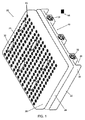
複数の導管(34)を有するファンボックス層(22)であって、導管の各々が、空気を導管から出し寝具システムを囲む領域内へ移動させるように構成されたファン(32)と連通しているファンボックス層(22)を含む寝具システム(20)が提供される。コンデンサ層(24)がファンボックス層の上方に位置付けられる。コンデンサ層は複数の出口ポート(42)を含み、出口ポートの各々は導管の1つと連通している。マットレス層(26)がコンデンサ層の上方に位置付けられる。マットレス層は、出口ポートの少なくとも1つと各々連通している複数の第1穴(60)を有する下部と、第1穴の1つと各々連通している複数の第2穴(62)を有する上部とを含む。上部は寝台面(28)を規定する。【選択図】図1A fan box layer (22) having a plurality of conduits (34), each of the conduits in communication with a fan (32) configured to move air out of the conduits and into a region surrounding the bedding system. A bedding system (20) is provided that includes a fan box layer (22). A capacitor layer (24) is positioned above the fan box layer. The capacitor layer includes a plurality of outlet ports (42), each of the outlet ports being in communication with one of the conduits. A mattress layer (26) is positioned above the capacitor layer. The mattress layer has a lower portion having a plurality of first holes (60) each communicating with at least one of the outlet ports and an upper portion having a plurality of second holes (62) each communicating with one of the first holes. Including. The upper part defines the bed surface (28). [Selection] Figure 1
Description
[0000] 本出願は、2014年1月13日に出願された米国特許出願第61/926,526号及び2014年1月13日に出願された米国特許出願第61/926,540号の利益を主張し、これらの両方が参照によりその全体が本明細書に組み込まれる。 [0000] This application is a benefit of US Patent Application No. 61 / 926,526 filed January 13, 2014 and US Patent Application No. 61 / 926,540 filed January 13, 2014. Both of which are incorporated herein by reference in their entirety.
[0001] 本開示は、概して、マットレスの就寝面から周囲の空気を引き離すように構成された温度制御されたベッドシステムを含むシステムに関し、その使用方法が含まれる。 [0001] The present disclosure relates generally to a system that includes a temperature controlled bed system configured to draw ambient air away from a mattress sleeping surface, including methods of use thereof.
[0002] 睡眠は、人々の生活の全ての局面において、人々が自らの最高の状態を感じ最高のパフォーマンスをするために極めて重要である。睡眠は、より良い健康への及び個人的な目標に到達するための必須の経路である。実際、睡眠は、新しい情報を記憶する能力から体重増加までの全てに影響を及ぼす。従って、人々にとって、快適で静穏な睡眠を達成するためには、自身の個人的な睡眠の好み及び身体のタイプの両方に適した寝具を使用することが不可欠である。 [0002] Sleep is extremely important in all aspects of people's lives in order for people to feel their best and perform at their best. Sleep is an essential pathway to reaching better health and personal goals. In fact, sleep affects everything from the ability to remember new information to weight gain. Therefore, it is essential for people to use bedding that is suitable for both their personal sleep preference and body type in order to achieve a comfortable and peaceful sleep.
[0003] マットレスは、適切な睡眠を達成する際の重要な局面である。従って、ユーザが睡眠中に最大の快適さを達成するように、ユーザの睡眠の好みに基づいて予め設定された温度を維持することのできるマットレスを提供することが有益である。マットレスの就寝面から周囲の空気を引き離すシステムを提供することが望ましい。就寝面の異なる領域に異なる温度環境を適用するように制御され得る温度制御システムを提供することもまた望ましい。本開示は、これらの先行技術に対する改良形態を説明する。 [0003] Mattresses are an important aspect in achieving proper sleep. Accordingly, it would be beneficial to provide a mattress that can maintain a preset temperature based on the user's sleep preferences so that the user achieves maximum comfort during sleep. It would be desirable to provide a system that draws ambient air away from the mattress sleeping surface. It would also be desirable to provide a temperature control system that can be controlled to apply different temperature environments to different areas of the sleeping surface. The present disclosure describes improvements over these prior art.
[0004] 一実施形態において、本開示の原理によると、複数の導管を有するファンボックス層を備える寝具システムが提供され、導管の各々は、空気を導管から出し寝具システムを囲む領域内へ移動させるように構成されたファンと連通する。コンデンサ層がファンボックス層の上方に位置付けられる。コンデンサ層は複数の出口ポートを含み、出口ポートの各々は導管の1つと連通する。マットレス層はコンデンサ層の上方に位置付けられる。マットレス層は、出口ポートの少なくとも1つと各々連通する複数の第1穴を有する下部と第1穴の1つと各々連通する複数の第2穴を有する上部とを含む。上部が寝台面を規定する。 [0004] In one embodiment, in accordance with the principles of the present disclosure, a bedding system is provided that includes a fan box layer having a plurality of conduits, each of the conduits moving air out of the conduits and into a region surrounding the bedding system. Communicate with a fan configured as described above. A capacitor layer is positioned above the fan box layer. The capacitor layer includes a plurality of outlet ports, each of the outlet ports communicating with one of the conduits. The mattress layer is positioned above the capacitor layer. The mattress layer includes a lower portion having a plurality of first holes each communicating with at least one of the outlet ports and an upper portion having a plurality of second holes each communicating with one of the first holes. The upper part defines the bed surface.
[0005] 本開示は、以下の図面を伴う特定の説明からより容易に明らかとなる。 [0005] The present disclosure will become more readily apparent from the specific description accompanying the following drawings.
[0025] 同様の参照符号は、全体にわたって同様の部品を指す。 [0025] Like reference numerals refer to like parts throughout.
[0026] 熱再利用システムを有する環境ベッド(ambient bed)の例示的な実施形態及び使用方法が、寝台面の温度を調整するために、空気がマットレスの寝台面から引き離されることを可能にする要素を含む寝具システムについて検討される。本開示は、本開示の一部を形成する添付図面に関連して本開示の以下の詳細な説明を参照することにより、より容易に理解され得る。本開示は、本明細書において説明される及び/又は図示される特定のデバイス、方法、条件又はパラメータへ限定されないこと、並びに、本明細書で使用される用語法は特定の実施形態を一例としてのみ説明することを目的とし、特許請求される開示を限定することを意図するものではないことを理解されたい。 [0026] An exemplary embodiment and method of use of an ambient bed with a heat recycling system allows air to be pulled away from the mattress couch surface to regulate the couch surface temperature A bedding system including elements is considered. The present disclosure may be understood more readily by reference to the following detailed description of the disclosure in connection with the accompanying drawings that form a part of this disclosure. This disclosure is not limited to the specific devices, methods, conditions, or parameters described and / or illustrated herein, and the terminology used herein is by way of example in particular embodiments. It should be understood that this is for purposes of illustration only and is not intended to limit the claimed disclosure.
[0027] また、添付の特許請求の範囲を含む明細書において使用されるとおり、単数形「a」「an」及び「the」は複数を含み、特定の数値への言及は、文脈からそうではないと明らかに指示されない限り、少なくともその特定の値を含む。範囲は、本明細書においては「約」又は「およそ」1つの特定の値から、及び/又は、「約」又は「およそ」別の特定の値までとして表されてもよい。このような範囲が表される場合、別の実施形態は一方の特定の値から、及び/又は、他方の特定の値までを含む。同様に、値が先行詞「約」を使用して近似値として表される場合、当該特定の値が別の実施形態を形成することを理解されたい。全ての空間的な言及、例えば水平、垂直、上部、上の方、下の方、下部、左及び右などは、例示のみを目的とするものであり、本開示の範囲内において変えられ得る。例えば、「上の方」及び「下の方」という言及は相対的であり、他方に対する関係においてのみ使用され、必ずしも「上位」及び「下位」ではない。 [0027] Also, as used in the specification, including the appended claims, the singular forms “a”, “an”, and “the” include the plural, and references to specific numerical values are out of context. Unless explicitly stated otherwise, includes at least that particular value. Ranges may be expressed herein as from “about” or “approximately” one particular value and / or to “about” or “approximately” another particular value. When such a range is expressed, another embodiment includes from the one particular value and / or to the other particular value. Similarly, when values are expressed as approximations, using the antecedent “about,” it should be understood that the particular value forms another embodiment. All spatial references, such as horizontal, vertical, top, top, bottom, bottom, left and right are for illustrative purposes only and may be varied within the scope of this disclosure. For example, the references “upper” and “lower” are relative and are used only in relation to the other, not necessarily “upper” and “lower”.
[0028] 以下の議論は、熱再利用システムを有する環境ベッド、関連する構成部品及び本開示の原理による環境ベッドシステムの使用方法の説明を含む。代替的な実施形態も開示される。ここで、添付図面に示される本開示の例示的な実施形態が詳細に参照される。図1〜図19を参照すると、寝具システム20の構成部品が示されている。
[0028] The following discussion includes a description of an environmental bed having a thermal recycling system, associated components, and methods of using the environmental bed system in accordance with the principles of the present disclosure. Alternative embodiments are also disclosed. Reference will now be made in detail to the exemplary embodiments of the present disclosure, which are illustrated in the accompanying drawings. Referring to FIGS. 1-19, the components of the
[0029] 寝具20の構成部品は、特定の用途に依存して、金属、ポリマー及び/又は複合材料を含む材料から作られ得る。例えば、寝具システム20の構成部品は、個別に又は集合的に、布又は織物、紙又はボール紙、セルロース系材料、生物分解性材料、プラスチック及び他のポリマー、金属、半剛性の及び剛性の材料などの材料から作られ得る。寝具システム20の様々な構成部品は、強度、剛性、弾性、性能及び耐久性など様々な望ましい特徴を達成するために、上記材料を含む複合材料を有してもよい。寝具システム20の構成部品はまた、個別に又は集合的に、上記材料のうちの2つ以上の組合せなど異種の材料から作られてもよい。寝具システム20の構成部品は押出成形、成型、射出成型、鋳造、プレス加工及び/又は機械加工され得る。本明細書において説明されるとおり、寝具システム20の構成部品はモノリシックに形成されても、一体的に接続されても、又はファスニング務歯及び/若しくは装置を含んでもよい。
[0029] The components of the
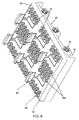
[0030] 図1〜図15に示される一実施形態において、寝具システム20は、ファンボックス層22、ファンボックス層24の上方に位置付けられたコンデンサ層24、及び、コンデンサ層24の上方に位置付けられたマットレス層26などの冷却部材を含む。一実施形態において、冷却部材は、ペルチェデバイス、ペルチェヒートポンプ、ソリッドステート冷却装置、又は熱電冷却器(TEC)であり得る。コンデンサ層24は、マットレス層26の寝台面28付近の温度を検出するための構成部品を含む。寝台面28付近の温度がユーザにより選択された温度から逸脱すると、コンデンサ層24は寝具システム20内の空気を加熱又は冷却し、加熱又は冷却された空気が寝台面28付近の温度をユーザにより選択された温度へ変えることができるように、この空気はファンボックス層22により寝具システム20から排出される。
In one embodiment illustrated in FIGS. 1-15, the
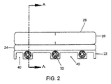
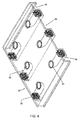
[0031] 図1〜図4に示されるとおり、ファンボックス層22は、例えば複数のファン32及び複数の導管34などファンボックス層22の他の構成部品を支持する、囲む及び/又は保護するように構成されたハウジング30を含む。特に、ハウジング30は、例えば図4に示されるとおり、ファン32の少なくとも1つをハウジング30の第1側部の壁内に、及びファン32の少なくとも1つをハウジング30の反対側の第2側部の壁内に含む。ファンボックス層22及び/又はハウジング30は、特定の用途の要件に依存して任意のサイズ又は形状を有し得ることが想定される。例えば、ファンボックス層22及び/又はハウジング30は、例えばツインサイズのマットレス、クイーンサイズのマットレス、キングサイズのマットレスなど特定のマットレスのサイズ及び形状に実質的に従うサイズにされ得る。
As shown in FIGS. 1-4, the
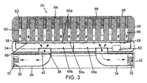
[0032] 一実施形態において、ハウジング30の第1側部の壁は、互いから間隔を空けて配された3つのファン32を含み、ハウジング30の第2側部の壁は、互いから間隔を空けて配された3つのファン32を含む。しかしながら、ハウジング30の第1側部の壁及びハウジング30の第2側部の壁は各々1つ又は複数のファン32を含んでもよいことが想定される。一実施形態において、図4に示されるとおり、ハウジング30の第1側部の壁におけるファン32の各々は、ハウジング30の第2側部の壁におけるファン32の1つと整列する。ファン32が各々導管34の空気チャネル内の空気をハウジング30から出し、例えば寝具システム20を囲む周囲の空気など寝具システム20を囲む領域内へ移動させ得るように、導管34のそれぞれの1つの内表面により規定される空気チャネルがファン32の1つと連通するように、ファン32は各々導管34の1つへ結合される。導管34は各々、ファン32の1つへ結合された第1端部36及び反対側の第2端部38から延出する。例えば図3及び4に示されるとおり、導管34は各々、第1端部36の開口部は第2端部38の開口部に垂直に延在するように、第1端部36と第2端部38との間に弓形部分を含む。
[0032] In one embodiment, the first side wall of the
[0033] 一実施形態において、図1に示されるとおり、ハウジング30は、隣接するファン32間及び/又はファン32とハウジング30の第1及び第2側部の間に延在するハウジング30の上側及び底側との間に凹部40を含む。一実施形態において、図4に示されるとおり、凹部40はハウジング30の第1及び第2側部の壁の間及び壁を通って延在し、ハウジング30の下の空気がハウジング30の第1側部からハウジング30の第2側部へ移動することを可能にする。一実施形態において、空気がハウジング30下を移動できないようにするために、ハウジング30は凹部40を含まず、凹部40の代わりに固体壁構成を有する。
[0033] In one embodiment, as shown in FIG. 1, the
[0034] コンデンサ層24は、図3に示されるとおり、導管34の第2端部38が各々コンデンサ層24の出口ポート42へ結合されるようにファンボックス層22の頂上に位置付けられ、その結果出口ポート42の開口部が、導管の第2端部38の開口部及び導管34の空気チャネルと連通する。図5に示されるとおり、出口ポート42はコンデンサ層24の底面44から上方へ延在し、コンデンサ層24の上面46の前で終端する。上面46及び底面44はそれらの間に中空の区画48を規定する。一実施形態において、図5に示されるとおり、区画48は、第1セクション48aと第2セクション48bとへ壁50により分割される。一実施形態において、壁50は、第1セクション48a内の空気が第2セクション48b内へ移動することができるように、及び、逆もまた同様であるように、複数の開口部50aの1つを含む。第1セクション48aの中身を見るために、上面46の、区画48の第1セクション48aを覆う部分は図5では除去されていることに留意されたい。一実施形態において、第1セクション48aは第2セクション48bの鏡像である。第1セクション48a及び第2セクション48bは各々1つ又は複数のシステムコントローラ52と1つ又は複数の温度調節器アセンブリ54とを含み、これらは以下でより詳細に検討される。
[0034] The
[0035] 図5に示されるとおり、コンデンサ層24の上面46は各出口ポート42と関連する複数の孔56を含む。図5に示される一実施形態において、上面46は各出口ポート42について8つの孔56を含む。しかしながら、上面46は、各出口ポート42について1つ又は複数の孔56を含んでもよいことが想定される。コンデンサ層24は、図6に示されるとおり、コンデンサ層24の上面46から上方へ延在する複数の気流孔デバイス58を含む。気流孔デバイス58は中空であり、各々孔56の1つと整列する。各気流孔デバイス58は孔56の1つと整列する。幾つかの実施形態において、コンデンサ層24の上面46は、図5に示されるとおり、整列された出口ポート42の間に位置付けられる複数の孔56aを含む。上面46は、整列された出口ポート42の各対の間に位置付けられる1つ又は複数の孔56aを含み得ることが想定される。コンデンサ層24は、図6に示されるとおり、コンデンサ層24の上面46から上方へ延在する複数の気流孔デバイス58aを含む。気流孔デバイス58aは、中空であり、各々孔56aの1つと整列する。
As shown in FIG. 5, the
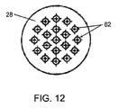
[0036] マットレス層26は、気流孔デバイス58、58aがマットレス層26の底面を通って延在する第1穴60と整列するように、コンデンサ層24の頂上に位置付けられる。第1穴60は、孔56の1つ及び出口ポート42の1つと整列し、又は、孔56aの1つと連通する。マットレス層26は、複数セットの第2穴62を含み、第2穴62の各セットは第1穴60の1つと連通している。すなわち、各第1穴60は、寝台面28を通って各々延在する複数の第2穴62と連通している。第1穴60は各々、マットレス層26の下部から寝台面28へ向かってマットレス層26の穴の直径が減少し、マットレス層26の穴の量が増大するように、第2穴62の各々の直径より大きい直径を有する。第1穴60は各々、第2穴62の各々に平行に延在する。一実施形態において、第2穴62の少なくとも1つはそれぞれの第1穴60の1つと同軸であり、第2穴62の少なくとも1つは、それぞれの第1穴60の1つにより規定される長手方向軸からオフセットされる。一実施形態において、図12に示されるとおり、第2穴62の各セットは円形の構成を有し、1つの第2穴62がセットの中心にあり、第2穴62の第1リングが第2穴62を中心として半径方向に延在し、第2穴62の第2リングが第2穴62の第1リングを中心として半径方向に延在する。
[0036] The
[0037] マットレス層26は、例えば図3、図13及び図14に示されるとおり、複数の空洞64であって、各々複数の第2穴62を通って延在するように第2穴62に垂直に延在する複数の空洞64を含む。空洞64の各々は出口ポート42の1つと整列する。一実施形態において、図14に示されるとおり、空洞64は各々、反対側にある線形部分とその間の弓形部分とを含む。線形部分は導管/気流チャネル部分として機能し、丸い中央部又は弓形部分はそこから引き出すための空きスペースとして機能する。一実施形態において、図14に示されるとおり、空洞64各々の中にはインサート66が配置される。一実施形態において、インサート66は例えば網状発泡体などの発泡体でできている。一実施形態において、空洞64は各々第2穴62の各々に垂直に延在する。一実施形態において、空洞64は寝台面28の下方に位置付けられる。一実施形態において、空洞64及びインサート66は、複数セットの第2穴62にわたって広がるように位置付けられ、空気を寝台面38から中へ引き出すのに十分なサイズの領域を提供する。実際、空洞が小さすぎる又は少なすぎる場合、ファン32がオンになっているときでも、第2穴62へ入る寝台面38からの空気の量が減少するように、空気を寝台面38から中へ引き出すのに十分な領域がないと思われる。空洞64及びインサート66により、第2穴62内で寝台面28に垂直に移動する空気が空洞64及びインサート66内で寝台面28に平行に移動することが可能になる。これにより、例えば、第2穴62の1つの中を寝台面28から離れる方向に垂直に移動する空気が、空洞64及びインサート66の1つへ入り、かつ、空気が第2穴62の別の1つの中を寝台面28から離れる方向に垂直に移動し続けることができるように空洞64及びインサート66内を横方向に移動することが可能となる。すなわち、空洞64及びインサート66は、スペースの部分的に開いた空洞を作り出し、これは複数の第2穴62と交わって、空気を空洞64から引き出すことを可能にする。空洞64及びインサート66の睡眠者に対する向きは、睡眠者の頭、胴、及び脚付近に位置付けられるように構成され、その理由は身体のこれらの領域が温度の上昇及び低下により最も頻繁に影響を受けるためである。
[0037] The
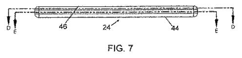
[0038] システムコントローラ52はプリント基板と様々な構成部品内で構築されるシステム全体にわたるセンサとを含んでもよい。システムコントローラ52は、ユーザがモジュール68を使って寝台面28にとって望ましい温度を選択することができるように、モジュール68へ有線又は無線で接続されてもよい。システムコントローラ52及び/又はモジュール68の機能は、例えばコンピュータプロセッサなどプロセッサにより実行されてもよい。温度調節器アセンブリ54がシステムコントローラ52へ有線又は無線で接続される。温度調節器アセンブリ54は、各温度調節器アセンブリ54のソフトフローチャネル70が寝台面28付近に位置付けられるように、マットレス層26の中へ延在する。一実施形態において、ソフトフローチャネル70は寝台面28と同一平面にある。一実施形態において、ソフトフローチャネル70は、寝台面28の上方に少なくともわずかに突出する。一実施形態において、ソフトフローチャネル70は、寝台面28の少なくともわずかに下方に位置付けられる。いずれの場合も、ソフトフローチャネル70は、寝台面28にわたる空気の流れを依然として可能にしながら、寝台面28上に横たわる睡眠者の負荷の少なくとも一部を担持するよう位置付けられる。
[0038] The
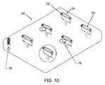
[0039] 温度調節器アセンブリ54は各々センサ72を含む。センサ72は、温度センサ、圧力センサ、湿気センサ、質量流センサなどを含み得る。センサ72は、チャネル70内の空気の少なくとも1つの特徴、例えば温度などを検出するように構成される。温度調節器アセンブリ54は各々、区画48内の空気の温度を調節するように構成されたデバイス、例えば熱電デバイスなどを含む。一実施形態において、図10に示されるとおり、寝具システム20は、温度調節器アセンブリ54及び温度調節器アセンブリ54と一体化された圧力センサ78から分離した湿気センサ76を含む。同様に、寝具システム20は、図11に示されるとおり、温度調節器アセンブリ54と一体化された温度センサ80と質量流センサ82とを含み得る。一実施形態において、湿気センサ76は、第1穴60又は第2穴62の1つの中に位置付けられる。温度調節器アセンブリ54及び/又はセンサ72の睡眠者に対する向きは、睡眠者の頭、胴、及び脚付近に位置付けられるように構成される。バイオメトリック解析アルゴリズム(biometric analysis algorithms)は、センサ72の厳密な配置を促すものである。従って、これは、寝台面28上の様々な位置におけるセンサ72の配置を決定する。一実施形態において、マットレス構成内に含まれる電気的構成部品は5ボルト以下で動作するものであり、最高の耐火性規格である。
[0039] The
[0040] 一実施形態において、寝具システム20は、睡眠者がマットレス層26上に横たわるときの睡眠者の下部腰椎及び臀部に対応する領域に位置付けられた圧力センサを含む。寝具システム20内の圧力センサアレイには2つの主な機能がある。第1は睡眠者の存在を示すために使用されることである。圧力センサアレイの第2の機能は、睡眠者の横たわっている方向、体重、及びおおよそのサイズを補間(interpolate)することである。圧力センサアレイはPIDシステムコントローラ及び/又はシステムコントローラ54と直接相互作用する。圧力センサアレイはまた、自動制御可能な快適性の制御及び機能の潜在的な使用を可能にする。
[0040] In one embodiment, the
[0041] ソフトフローチャネル70の少なくとも1つの中の空気の温度がモジュール68を使用して選択された温度より高い、それ未満である、又はそれに等しいかどうか検出し、システムコントローラ52へそれを示す信号を送るために、センサ72が使用されてもよい。ソフトフローチャネル70の1つの中の空気の温度がモジュール68を使用して選択された温度より高い場合、このような空気の温度がモジュール68を使用して選択された温度以下であるかそれに等しくなるように、システムコントローラ52は、熱電デバイス74に区画48内の空気を変えさせる温度調節器アセンブリ54へ信号を送る。システムコントローラ52及び/又は温度調節器アセンブリ54は信号をファン32へ送り、ファンをオンにし、空気を区画48から吹き出させ寝具システム20を囲む領域へ吹き込ませる。空気が区画48から出て寝具システム20を囲む領域へ入るよう移動するときに作り出される負圧は、モジュール68を使用して選択された温度より高い温度を有する寝台面28で空気を第2穴62内へ移動させる。空気は第2穴62から第1穴60内へ移動する。空気は、導管34の空気チャネルを通って寝具システム20を囲む領域内へ移動するように、第1穴60から出口ポート42内へ移動する。空気は、寝具システム20を囲む領域における周囲温度を経時的に変化させる。
[0041] Detect whether the temperature of the air in at least one of the
[0042] 同様に、ソフトフローチャネル70の1つの中の空気の温度がモジュール68を使用して選択された温度未満である場合、このような空気の温度がモジュール68を使用して選択された温度以上になるように、システムコントローラ52は、熱電デバイス74に区画48内の空気を変えさせる温度調節器アセンブリ54へ信号を送る。システムコントローラ52及び/又は温度調節器アセンブリ54は、信号をファン32へ送り、ファンをオンにし、空気を区画48から吹き出させ寝具システム20を囲む領域へ吹き込ませる。空気が区画48から出て寝具システム20を囲む領域へ入るよう移動するときに作り出される負圧は、モジュール68を使用して選択された温度未満の温度を有する寝台面28で空気を第2穴62内へ移動させる。空気は第2穴62から第1穴60内へ移動する。空気は、導管34の空気チャネルを通って寝具システム20を囲む領域内へ移動するように、第1穴60から出口ポート42内へ移動する。空気は、寝具システム20を囲む領域における周囲温度を経時的に変化させる。
[0042] Similarly, if the temperature of the air in one of the
[0043] 一実施形態において、寝具システム20は、寝台面28から空気を連続的に引き出し、寝具システム20内の空気の温度を変え、次いで、ソフトフローチャネル70内の空気がモジュール68を使用して選択された温度に等しいことをセンサ72が検出するまで、寝具システム20を囲む領域内へ空気を連続的に移動させるように構成されてもよい。すなわち、寝具システム20は、ソフトフローチャネル70内の空気が各々モジュール68を使用して選択された温度に等しい温度を有することをセンサ72が検出するまで、先行する段落において説明された方法で作動する。システムコントローラ52は、次いで、温度調節器アセンブリ54に熱電デバイス74をオンにさせる温度調節器アセンブリ54への信号及び/又はファン32をオンにする信号を終わらせる。代替的に、システムコントローラ52は、温度調節器アセンブリ54に熱電デバイス74をオフにさせる信号及び/又はファン32をオフにする信号を温度調節器アセンブリ54へ送ることができる。システムコントローラ52が上記で検討された信号を提供するポイントである、ソフトフローチャネル70の少なくとも1つの中の空気の温度がモジュール68を使用して選択された温度より高い又はそれ未満であることをセンサ72が検出しない限り及び検出するときまで、システムコントローラ52と温度調節器アセンブリ54との間に信号はない。最終結果は、睡眠者と睡眠者の環境との間の環境平衡を作り出す及び達成することである。
[0043] In one embodiment, the
[0044] 一実施形態において、コンデンサ層24の第1セクション48a及び第2セクション48bは各々、独立して制御され得るシステムコントローラ52と温度調節器アセンブリ54とを有する。すなわち、寝台面28の、コンデンサ層24の第1セクション48aの上方の部分が、寝台面28の、コンデンサ層24の第2セクション48bの上方の部分と異なる温度へ設定され得るように、第1セクション48aのシステムコントローラ52及び1つ又は複数の温度調節器アセンブリは、第2セクション48aのシステムコントローラ52及び1つ又は複数の温度調節器アセンブリ54から独立して設定及び制御され得る。一実施形態において、これは、寝台面28の、第1セクション48aの上方の部分について望ましい温度を選択することにより達成され得る。第1セクション48aの1つ又は複数の温度調節器アセンブリ54のセンサ72が、第1セクション48aの温度調節器アセンブリ54のソフトフローチャネル70の少なくとも1つの中の空気の温度が、モジュール68を使用して選択された温度より高い、それ未満である、又はそれに等しいかどうか検出し、第1セクション48aのシステムコントローラ52へそれを示す信号を送るのに使用されてもよい。第1セクション48aのソフトフローチャネル70の1つの中の空気の温度がモジュール68を使用して選択された温度より高い場合、このような空気の温度がモジュール68を使用して選択された温度未満であるかそれに等しくなるように、第1セクション48aのシステムコントローラ52は、第1セクション48aの熱電デバイス74に区画48a内の空気を変えさせる第1セクション48aの温度調節器アセンブリ54へ信号を送る。第1セクション48aのシステムコントローラ52及び/又は温度調節器アセンブリ54は、ファンボックス層22の第1セクション48aの真下の部分にあるファン32へ信号を送り、ファン32をオンにし、空気を区画48aから吹き出させ寝具システム20を囲む領域内へ吹き込ませる。空気が区画48の第1セクション48aから出て寝具システム20を囲む領域内へ移動するときに作り出される負圧は、モジュール68を使用して選択された温度より高い温度を有する、寝台面28の、第1セクション48aの上方の部分の空気を、マットレス層26の、第1セクション48aの真上の部分の第2穴62内へ移動させる。空気は、マットレス層26の、第1セクション48aの真上の部分の第2穴62から第1穴60内へ移動する。空気が、ファンボックス層22の、第1セクション48aの真下の部分の導管34の空気チャネルを通って寝具システム20を囲む領域内へ移動するように、空気は、マットレスの、第1セクション48aの真上の部分の第1穴60から第1セクション48aの出口ポート42内へ移動する。空気は、寝具システム20を囲む領域における周囲温度を経時的に変化させる。システム20はまた、上記で検討された方法で、第1セクション48aのソフトフローチャネル70の1つの中の空気の温度がモジュール68を使用して選択された温度未満である場合、第1セクション48aの上方の寝台面28付近の空気の温度を低下させるのに使用されてもよい。
[0044] In one embodiment, the
[0045] 同様に、寝台面の、コンデンサ層24の第2セクション48bの真上の部分の温度を設定するために、ユーザは、寝台面28の、第2セクション48bの上方の部分についての望ましい温度を選択する。第2セクション48bの1つ又は複数の温度調節器アセンブリ54のセンサ72が、第2セクション48bの1つ又は複数の温度調節器アセンブリ54のソフトフローチャネル70の少なくとも1つの中の空気の温度がモジュール68を使用して選択された温度より高い、それ未満である、又はそれに等しいかどうか検出し、第2セクション48bのシステムコントローラ52へそれを示す信号を送るのに使用されてもよい。第2セクション48bのソフトフローチャネル70の1つの中の空気の温度がモジュール68を使用して選択された温度より高い場合、このような空気の温度がモジュール68を使用して選択された温度未満であるかそれに等しくなるように、第2セクション48bのシステムコントローラ52は、第2セクション48bの熱電デバイス74に区画48内の空気を変えさせる第2セクション48bの温度調節器アセンブリ54へ信号を送る。第2セクション48bのシステムコントローラ52及び/又は温度調節器アセンブリ54は、ファンボックス層22の、第2セクション48bの真下の部分におけるファン32へ信号を送り、ファン32をオンにし、空気を区画48bから吹き出させ寝具システム20を囲む領域へ吹き込ませる。空気が区画48の第2セクション48bから出て寝具システム20を囲む領域内へ移動するときに作り出される負圧は、モジュール68を使用して選択された温度より高い温度を有する寝台面28の、第2セクション48bの上方の部分の空気を、マットレス層26の、第2セクション48bの真上の部分の第2穴62内へ移動させる。空気は、マットレス層26の、第2セクション48bの真上の部分の第2穴62から第1穴60内へ移動する。空気が、ファンボックス層22の、第2セクション48bの真下の部分の導管34の空気チャネルを通り、寝具システム20を囲む領域内へ移動するように、空気は、マットレス層26の、上方第2セクション48bの真上の部分の第1穴60から出て第1セクション48aの出口ポート42内へ移動する。空気は、寝具システム20を囲む領域における周囲温度を経時的に変化させる。システム20はまた、上記で検討した方法で、第2セクション48bのソフトフローチャネル70の1つの中の空気の温度が、モジュール68を使用して選択された温度未満である場合、第2セクション48bの上方の寝台面28付近の空気の温度を下げるのに使用されてもよい。
[0045] Similarly, in order to set the temperature of the portion of the couch surface just above the
[0046] 熱電デバイスが冷却モードにある場合、熱電デバイスは熱気を排出しなければならず、加熱モードにある場合は、冷気を排出しなければならない。かくして、一実施形態において、コンデンサ層24の第1セクション48aの1つ又は複数の温度調節器アセンブリの熱電デバイス74は、コンデンサ層24の第2セクション48bの温度調節器アセンブリ54の熱電デバイス74と空気を交換するように構成される。これにより、コンデンサ層24の区画48の第1セクション48a又は第2セクション内の温度を変えるために熱電デバイス74により必要とされる仕事の量を制限することにより、寝具システム20の効率が上がり得る。一実施形態において、第1セクション48aにおける空気は、第2セクション48bにおける空気と、ファンボックス層22の壁50における開口部50aを通じて交換され得る。このような構成は、区画48の第1セクション48aの上方の睡眠者が冷却されており、第2セクション48bの上方の睡眠者が温められているとき、熱気を区画48の第2セクション48b内へ供給する熱再利用システムとして機能する。反対に、睡眠者を温めている第2セクション48bにおいて熱電デバイス74により作られる冷気は、睡眠者を冷却している熱電デバイス74を含む第1セクション48aへ送られる。
[0046] When the thermoelectric device is in the cooling mode, the thermoelectric device must exhaust hot air, and when it is in the heating mode, it must exhaust cold air. Thus, in one embodiment, the
[0047] 熱再利用システムの一実施形態において、第1セクション48aの1つ又は複数の温度調節器アセンブリ54の熱電デバイス74が第1セクション48aの上方の寝台面28付近の温度を上昇させるための信号を受信すると、第1セクション48aの1つ又は複数の温度調節器アセンブリ54の熱電デバイス74は、第1セクション48aの上方の寝台面28付近の温度を選択された温度へ戻すために、熱気を作り出す際に、冷気を排出することができる。冷気は次いで、第2セクション48bの1つ又は複数の温度調節器アセンブリ54の熱電デバイス74により、第2セクション48bの上方の寝台面28付近の温度を下げるために、第2セクション48bの上方の寝台面28付近の空気を冷却するのに使用されてもよい。これにより、システムの効率を上げるために、システム20の一方の側からの空気を「再利用」し、システム20の反対側により用いることが可能になる。同じ方法で、第2セクション48bの1つ又は複数の温度調節器アセンブリ54の熱電デバイス74は、第2セクション48bの上方の寝台面28付近の温度を選択された温度へ戻すために熱気を生じる際、冷気を排出してもよい。冷気は次いで、第1セクション48aの1つ又は複数の温度調節器アセンブリ54の熱電デバイス74により、第1セクション48aの上方の寝台面28付近の温度を下げるために、第1セクション48aの上方の寝台面28付近の空気を冷却するために使用されてもよい。
[0047] In one embodiment of the thermal reuse system, the
[0048] 同様に、第1セクション48aの1つ又は複数の温度調節器アセンブリの熱電デバイス74が第1セクション48aの上方の寝台面28付近の温度を下げるための信号を受信すると、第1セクション48aの1つ又は複数の温度調節器アセンブリ54の熱電デバイス74が、第1セクション48aの上方の寝台面28付近の温度を選択された温度へ戻すために冷気を生じさせる際に熱気を排出してもよい。熱気は次いで、第2セクション48bの1つ又は複数の温度調節器アセンブリ54の熱電デバイス74により、第2セクション48bの上方の寝台面28付近の温度を上げるために、第2セクション48bの上方の寝台面28付近の空気を加熱するために使用されてもよい。これにより、システムの効率を上げるために、システム20の一方の側からの空気を「再利用し」、システム20の反対側により使用することが可能となる。同じ方法で、第2セクション48bの1つ又は複数の温度調節器アセンブリ54のデバイス74は、第2セクション48bの上方の寝台面28付近の温度を選択された温度へ戻すために冷気を生じさせる際に、熱気を排出することができる。熱気は次いで、第1セクション48aの1つ又は複数の温度調節器アセンブリ54の熱電デバイス74により、第1セクション48aの上方の寝台面28付近の温度を上げるために、第1セクション48aの上方の寝台面28付近の空気を加熱するのに使用されてもよい。熱電デバイス74は、例えばペルチェデバイス、ペルチェヒートポンプ、ソリッドステート冷却装置、又は熱電冷却器(TEC)と呼ばれる計器であり得る。
[0048] Similarly, when the
[0049] 一実施形態において、コンデンサ層24の区画48の第1セクション48aの熱電デバイス、及びコンデンサ層24の区画48の第2セクション48bの熱電デバイスは、コンデンサ層24の外へ空気を排出するための出口すなわち排出口84を含み、その結果、第1セクション48aにおける熱電デバイス又は第2セクション48bにおける熱電デバイスが熱気を(寝台面28付近の空気の温度を上げるために)生じるとき、第1セクション48aにおける熱電デバイス、又は第2セクション48bにおける熱電デバイスから排出される冷気は区画48内に含まれない。むしろ、冷気はコンデンサ層24の外へ排出される。同様に、第1セクション48aにおける熱電デバイス又は第2セクション48bにおける熱電デバイスが冷気を(寝台面28付近の空気の温度を下げるために)生じるとき、第1セクション48aにおける熱電デバイス又は第2セクション48bにおける熱電デバイスから排出される熱気は、区画48内に含まれない。むしろ、熱気は、コンデンサ層24の外へ排出される。これにより、第2セクション48bにおける熱電デバイスが第2セクション48bの上方の寝台面28付近の空気を冷却すると同時に第1セクション48aにおける熱電デバイスが第1セクション48aの上方の寝台面28付近の空気を冷却することが可能になり、又は、第2セクション48bにおける熱電デバイスが第2セクション48bの上方の寝台面28付近の空気を加熱すると同時に第1セクション48aにおける熱電デバイスが第1セクション48aの上方の寝台面28付近の空気を加熱することが可能になる。
[0049] In one embodiment, the thermoelectric devices in the
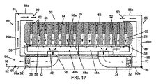
[0050] 図16〜図19に示す一実施形態において、寝具システム20は、図1〜図15に示される実施形態の場合のように調整された空気を寝具システム20を囲む領域、例えば寝具システム20が位置付けられる部屋などへ向かわせるというよりもむしろ、調整された空気を寝台面28付近へ向かわせるように構成される。すなわち、図16〜図18に示される実施形態において、調整された空気は、寝具システム20が位置付けられる部屋の空気を調節するというよりむしろ、寝台面28の温度を調節するために寝台面28(寝台面28付近の領域)へ向けられる。この構成により、部屋寝具システム20の空気の温度が調節されるときに生じるよりも、寝台面28の温度がより速やかに調節され得ることが想定される。従って、寝具システム20は、調整された空気が寝台面28付近の気流ポスト86を出ることができるように、ファン32の1つからの調整された空気が気流ポスト86へ向けられ得るように、ファンボックス層22へ結合された少なくとも1つの気流ポスト86を含む。一実施形態において、寝具システム20は、ファン32の各々に隣接するファンボックス層22へ結合された気流ポスト86を含む。すなわち、調整された空気が寝台面28に隣接した気流ポスト86から出られるように、ファン32の各々からの調整された空気が気流ポスト86の1つ内へ向けられるように、各ファン32は気流ポスト86の1つへ結合される。一実施形態において、気流ポスト86は各々、寝台面28に平行に延在する第1部分86a、寝台面28に垂直に延在する第2部分86b、及び寝台面28に平行に延在する第3部分86cを含む。気流ポスト86の内表面は、部分86a、86b、86cを通じて連続的である通路88を規定する。
[0050] In one embodiment shown in FIGS. 16-19, the
[0051] 図16及び図16Aに示される一実施形態において、気流ポスト86の第3部分86cは、ファン32が、調整された空気をファンボックス層22から吹き出し第1部分86aに吹き込むように、寝台面28に平行に延在する開口部90を含む。調整された空気は第1部分86aから第2部分86b内へ移動する。図16及び図16Aに示されるとおり、調整された空気が寝台面28に平行移動するように、調整された空気は第2部分86から第3部分86c内へ移動し、そこで開口部90を通じて第3部分86から出る。図17に示される一実施形態において、気流ポスト86の開口部90は、気流ポスト86内の調整された空気が開口部90を寝台面28に垂直な方向に出るように、寝台面28に垂直に延在する。一実施形態において、第3部分86cにより規定される平面における気流の方向を調節するために、第3部分86cは第2部分86bに対して回転可能である。図16〜図17に示されるとおり、第2部分86bは、第3部分86bを寝台面28の上方に位置付けることを可能にする高さを有する。これにより、調整された空気が寝台面28の上を移動することが可能になる。図16〜図17に示されるとおり、第3部分86は、調整された空気が、マットレス層26の外周というよりむしろマットレス層26の中心の方へ向けられるように、第3部分86がマットレス層26の少なくとも一部にわたって延在することを可能にする長さを有する。
[0051] In one embodiment shown in FIGS. 16 and 16A, the
[0052] 図16〜図19に示される一実施形態において、気流ポスト86は、ファン32からの調整された空気が、睡眠者の好みに応じて、寝台面28付近に又は寝具システム20を囲む領域内にのいずれかに向けられることを可能にするための特徴部を含む。例えば、気流ポスト86の第2部分86bは、図16に示される閉位置と図17に示される開位置との間で可動であるフラップ92を含み得る。フラップ92が閉位置から開位置へ移動すると、調整された空気が寝具システム20を囲む領域内へ移動するように、ファン32が調整された空気を開口部94を通じて寝台面28に平行な方向に移動させることができるように、フラップ92は図17に示される開口部94を露出させ、そのような領域における温度を、室温が選択された温度に一致するまで調節する。一実施形態において、フラップ92は、フラップ92をヒンジ96を中心として回転又は枢動させることにより、開位置と閉位置との間を移動する。一実施形態において、フラップ92は、フラップ92を閉位置に維持するように構成されたラッチ又はタブ98を含む。図17に示されるとおりいくつかの気流ポスト86のフラップ92が閉位置にあってもよく、一方で他の気流ポスト86の他のフラップが開位置にあってもよいことが想定される。これにより、調整された空気を寝台面28付近へ、及び寝具システム20を囲む領域内へ同時に向けることが可能になる。
[0052] In one embodiment shown in FIGS. 16-19, airflow post 86 allows conditioned air from
[0053] 図19に示される一実施形態において、気流ポスト86の第2部分86bは図16〜図18に示されるものと比べて長さが短い。図19に示されるとおり、第2部分86bの長さが短いことにより、気流ポスト86の開口部90が調整された空気をマットレス層26の寝台面28とマットレス層26の反対側の底面との間の、マットレス層の部分へ向けるように、第3部分86cを位置付けることが可能になる。気流ポスト86の第3部分86cもまた、第3部分86が、マットレス層26の上とは対照的に、マットレス層26の側部へ位置付けられ得るように、図16及び図16Aに示されるものと比べて長さが短い。一実施形態において、第2部分86bの長さが好みに応じて軸方向に短く又は長くされ得るように、気流ポスト86の第2部分86bは入れ子式になっている。例えば、調整された空気が寝台面28の上方へ向けられることを睡眠者が望む場合、睡眠者は、図16〜18に示されるとおり、第3部分86cが寝台面28の上方に位置付けられるように、第2部分86bの高さを調節することができる。調整された空気が寝台面28の下方に向けられることを睡眠者が求めた場合、睡眠者は、図19に示されるとおり、第3部分86c及び/又は開口部90が寝台面28の下方に位置付けられるように、第2部分86bの高さを調節できる。
[0053] In one embodiment shown in FIG. 19, the
[0054] 本明細書において開示された実施形態に対して様々な修正がなされ得ることを理解されたい。例えば、任意の一実施形態の特徴部は、他の任意の実施形態の特徴部と組合せられ得る。従って、上記説明は限定するものとして解釈されてはならず、様々な実施形態の例示としてのみ解釈されるべきである。当業者は本明細書に添付の特許請求の範囲及び趣旨内の他の修正形態に想到するだろう。
[0054] It should be understood that various modifications can be made to the embodiments disclosed herein. For example, the features of any one embodiment may be combined with the features of any other embodiment. Therefore, the above description should not be construed as limiting, but merely as exemplifications of various embodiments. Those skilled in the art will envision other modifications within the scope and spirit of the claims appended hereto.
Claims (20)
複数の導管を備えるファンボックス層であって、前記導管の各々が、空気を前記導管から出して、前記寝具システムを囲む領域内へ移動させるように構成されたファンと連通する、ファンボックス層と、
複数の出口ポートを備える、前記ファンボックス層の上方に位置付けられたコンデンサ層であって、前記出口ポートの各々が前記導管の1つと連通する、コンデンサ層と、
前記出口ポートの少なくとも1つと各々連通する複数の第1穴を有する下部と前記第1穴の1つと各々連通する複数の第2穴を有する上部とを含む前記コンデンサ層の上方に位置付けられたマットレス層であって、前記上部が寝台面を規定する、マットレス層と、を備える寝具システム。 A bedding system,
A fan box layer comprising a plurality of conduits, each of the conduits being in communication with a fan configured to move air out of the conduits and into a region surrounding the bedding system; ,
A capacitor layer positioned above the fan box layer, comprising a plurality of outlet ports, wherein each of the outlet ports communicates with one of the conduits;
A mattress positioned above the capacitor layer including a lower portion having a plurality of first holes each communicating with at least one of the outlet ports and an upper portion having a plurality of second holes each communicating with one of the first holes. A bedding system comprising: a mattress layer, wherein the upper portion defines a bed surface.
Applications Claiming Priority (5)
| Application Number | Priority Date | Filing Date | Title |
|---|---|---|---|
| US201461926526P | 2014-01-13 | 2014-01-13 | |
| US201461926540P | 2014-01-13 | 2014-01-13 | |
| US61/926,540 | 2014-01-13 | ||
| US61/926,526 | 2014-01-13 | ||
| PCT/US2015/011179 WO2015106258A1 (en) | 2014-01-13 | 2015-01-13 | Ambient bed having a heat reclaim system |
Publications (2)
| Publication Number | Publication Date |
|---|---|
| JP2017501858A true JP2017501858A (en) | 2017-01-19 |
| JP6625556B2 JP6625556B2 (en) | 2019-12-25 |
Family
ID=52440868
Family Applications (1)
| Application Number | Title | Priority Date | Filing Date |
|---|---|---|---|
| JP2016563901A Active JP6625556B2 (en) | 2014-01-13 | 2015-01-13 | Environmental bed with heat reuse system |
Country Status (16)
| Country | Link |
|---|---|
| US (6) | US9756952B2 (en) |
| EP (1) | EP3094213B1 (en) |
| JP (1) | JP6625556B2 (en) |
| KR (2) | KR102317439B1 (en) |
| CN (2) | CN110169674A (en) |
| AU (13) | AU2015204480A1 (en) |
| BR (1) | BR112016016295B1 (en) |
| CA (1) | CA2936688C (en) |
| CL (1) | CL2016001782A1 (en) |
| CR (1) | CR20160356A (en) |
| HK (1) | HK1225241A1 (en) |
| IL (1) | IL246728B (en) |
| MX (1) | MX2016009104A (en) |
| NZ (1) | NZ722015A (en) |
| RU (1) | RU2644101C1 (en) |
| WO (1) | WO2015106258A1 (en) |
Families Citing this family (51)
| Publication number | Priority date | Publication date | Assignee | Title |
|---|---|---|---|---|
| US7877827B2 (en) | 2007-09-10 | 2011-02-01 | Amerigon Incorporated | Operational control schemes for ventilated seat or bed assemblies |
| US9125497B2 (en) * | 2007-10-15 | 2015-09-08 | Gentherm Incorporated | Climate controlled bed assembly with intermediate layer |
| CN104523071A (en) | 2008-07-18 | 2015-04-22 | 金瑟姆股份公司 | Climate controlled bed assembly |
| US8332975B2 (en) | 2009-08-31 | 2012-12-18 | Gentherm Incorporated | Climate-controlled topper member for medical beds |
| NZ722015A (en) * | 2014-01-13 | 2021-09-24 | Bedgear Llc | Ambient bed having a heat reclaim system |
| US20170202362A1 (en) * | 2014-04-10 | 2017-07-20 | Neven Sleep, Llc | Ventilating sleep system |
| US9888785B2 (en) | 2014-04-21 | 2018-02-13 | Casper Sleep Inc. | Mattress |
| FI125745B (en) * | 2014-07-18 | 2016-01-29 | Maricare Oy | The sensor arrangement |
| WO2016093886A1 (en) * | 2014-12-12 | 2016-06-16 | Bedgear, Llc | Pillow having multiple porosity ports |
| JP6499550B2 (en) * | 2015-08-19 | 2019-04-10 | トヨタ紡織株式会社 | bed |
| USD822409S1 (en) | 2015-11-16 | 2018-07-10 | Casper Sleep Inc. | Pillow set |
| WO2018022760A1 (en) * | 2016-07-27 | 2018-02-01 | Philip Sherman | Climate controlled mattress system |
| EP3490440B1 (en) | 2016-07-29 | 2023-07-05 | Bryte, Inc. | A method, performed by at least one processor, for assisting in adjusting a user sleep platform environment with localized pressure regions across the sleep surface |
| US10736300B2 (en) | 2016-08-16 | 2020-08-11 | Casper Sleep Inc. | Dog mattress |
| US11064812B2 (en) * | 2017-02-01 | 2021-07-20 | Charles Thornburg | Vented bedding system and method of use |
| US11134790B2 (en) | 2017-04-10 | 2021-10-05 | Bedgear, Llc | Negative pressure mattress system |
| US10034410B1 (en) * | 2017-04-26 | 2018-07-24 | Chroma Ate Inc. | Support apparatus |
| US10932436B2 (en) | 2017-07-24 | 2021-03-02 | Henry Bennie Marshall, III | Air filtration and control system for an animal housing |
| CA3072933A1 (en) | 2017-08-14 | 2019-02-21 | Casper Sleep Inc. | Mattress containing ergonomic and firmness-regulating endoskeleton |
| US10772438B2 (en) | 2017-08-23 | 2020-09-15 | Sleep Number Corporation | Air system for a bed |
| NL2019946B1 (en) * | 2017-11-21 | 2019-05-27 | Berco Truck Components B V | Climate controlled resting unit for use inside a cab of a vehicle |
| USD862104S1 (en) | 2018-03-21 | 2019-10-08 | Casper Sleep Inc. | Platform bed frame |
| WO2019209733A1 (en) * | 2018-04-23 | 2019-10-31 | Casper Sleep Inc. | Temperature-regulating mattress |
| US11160386B2 (en) | 2018-06-29 | 2021-11-02 | Tempur World, Llc | Body support cushion with ventilation system |
| US10973337B2 (en) * | 2018-06-29 | 2021-04-13 | Ergomotion, Inc. | Compact cardridge fan systm for environmental control in an articulating bed |
| JP2022508584A (en) | 2018-10-03 | 2022-01-19 | ユーベッド・ベー・フェー | Body support assembly |
| NL2021752B1 (en) | 2018-10-03 | 2020-05-11 | Ubed B V | Body support assembly |
| NL2021753B1 (en) | 2018-10-03 | 2020-05-11 | Ubed B V | Body support assembly |
| USD885640S1 (en) | 2018-10-23 | 2020-05-26 | Casper Sleep Inc. | Lamp assembly |
| US20200237106A1 (en) * | 2019-01-25 | 2020-07-30 | Bedgear, Llc | Bedding system |
| US11357209B2 (en) * | 2019-02-01 | 2022-06-14 | Henry Bennie Marshall, III | Pet bed platform with air filtration system |
| WO2021002510A1 (en) * | 2019-07-03 | 2021-01-07 | 유영도 | Electric heater for mattress |
| USD908398S1 (en) | 2019-08-27 | 2021-01-26 | Casper Sleep Inc. | Mattress |
| USD921531S1 (en) | 2019-09-10 | 2021-06-08 | Casper Sleep Inc. | Zipper |
| JP2023500777A (en) | 2019-09-27 | 2023-01-11 | ユーベッド・ベー・フェー | body support assembly |
| NL2023913B1 (en) | 2019-09-27 | 2021-05-27 | Ubed B V | Body support assembly |
| USD927889S1 (en) | 2019-10-16 | 2021-08-17 | Casper Sleep Inc. | Mattress layer |
| US11653630B2 (en) * | 2019-12-10 | 2023-05-23 | Craig William Lundin, JR. | Gas and liquid supply system |
| AU2020417816A1 (en) | 2020-01-03 | 2022-06-23 | Sleep Number Corporation | Bed airflow and temperature control |
| KR20220156652A (en) * | 2020-04-06 | 2022-11-25 | 퍼플 이노베이션, 엘엘씨 | ventilated mattresses |
| US11786046B2 (en) * | 2020-04-07 | 2023-10-17 | Lg Electronics Inc. | Bed |
| KR20210124673A (en) * | 2020-04-07 | 2021-10-15 | 엘지전자 주식회사 | Bed |
| JP2023545868A (en) * | 2020-10-23 | 2023-10-31 | アレン チャンバーズ,ジョージ | 3D mattress system with environmental control |
| CN112545245B (en) * | 2020-12-09 | 2022-04-22 | 江苏卧尔康家居用品有限公司 | Mould-proof antibacterial electric mattress |
| EP4304419A1 (en) * | 2021-03-10 | 2024-01-17 | Pure-development 1 B.V. | Environmentally conditioned furniture |
| US11678748B2 (en) * | 2021-03-10 | 2023-06-20 | Pure-Development 1 B.V. | Upholstery support arrangement, including airflow arrays for conditioned furniture, and associated systems and methods |
| NL2027736B1 (en) * | 2021-03-10 | 2022-09-27 | Pure Dev 1 B V | Upholstery support arrangement, including airflow arrays for conditioned furniture, and associated systems and methods |
| US11744378B2 (en) | 2021-03-10 | 2023-09-05 | Pure-Development 1 B.V. | Support construction for conditioned furniture, and associated systems and methods |
| US11779127B2 (en) | 2021-03-10 | 2023-10-10 | Pure-Development 1 B.V. | Air handling unit for environmentally conditioned furniture, and associated systems and methods |
| EP4304423A1 (en) * | 2021-03-10 | 2024-01-17 | Pure-development 1 B.V. | Upholstery support arrangement, including airflow arrays for conditioned furniture |
| US20220287472A1 (en) * | 2021-03-10 | 2022-09-15 | Pure-Development 1 B.V. | Environmentally conditioned furniture, and associated systems and methods |
Citations (8)
| Publication number | Priority date | Publication date | Assignee | Title |
|---|---|---|---|---|
| JPS5697416A (en) * | 1979-12-29 | 1981-08-06 | Kenrou Motoda | Quiet sleep apparatus |
| JPH05277021A (en) * | 1992-03-31 | 1993-10-26 | Shin Meiwa Ind Co Ltd | Bed with temperature regulating function, and environmental temperature regulating equipment |
| JPH073403U (en) * | 1993-06-24 | 1995-01-20 | 株式会社マック計算センター | Bedding with air-conditioning air outlet |
| US5546618A (en) * | 1995-03-16 | 1996-08-20 | Beedy; Robert G. | Ventilated mattress for infants |
| JP2003289990A (en) * | 2002-03-29 | 2003-10-14 | Panatekku:Kk | Apparatus for improving sleep environment |
| JP2005111013A (en) * | 2003-10-09 | 2005-04-28 | Hitachi Hometec Ltd | Berth with deodorization device |
| JP2006175249A (en) * | 1993-11-22 | 2006-07-06 | Amerigon Inc | Device realizing variable seat temperature |
| JP2007082755A (en) * | 2005-09-22 | 2007-04-05 | Ogaki Sangyo Kk | Mattress |
Family Cites Families (74)
| Publication number | Priority date | Publication date | Assignee | Title |
|---|---|---|---|---|
| US2371788A (en) * | 1942-08-07 | 1945-03-20 | Weeber Paul | Cushion |
| US3266064A (en) * | 1963-03-29 | 1966-08-16 | Figman Murray | Ventilated mattress-box spring combination |
| DE2217759A1 (en) * | 1972-04-13 | 1973-10-25 | Calottan Ag | AIR CONVEYING UPHOLSTERY |
| US3928876A (en) * | 1974-08-19 | 1975-12-30 | Louis J Starr | Bed with circulated air |
| GB1532219A (en) * | 1975-06-28 | 1978-11-15 | Howorth Air Eng Ltd | Mattress |
| US4825488A (en) * | 1988-04-13 | 1989-05-02 | Bedford Peter H | Support pad for nonambulatory persons |
| US4866800A (en) * | 1988-05-19 | 1989-09-19 | Bedford Peter H | Support pad for nonambulatory persons |
| US4939804A (en) * | 1989-07-24 | 1990-07-10 | Grant William N | Bed ventilating apparatus and method |
| US5058227A (en) * | 1990-12-11 | 1991-10-22 | George Schoenfelder | Under-bed humidifier |
| US5474362A (en) * | 1991-06-26 | 1995-12-12 | Albecker, Iii; Walter J. | Cushions having internal support member |
| US5226188A (en) * | 1992-06-26 | 1993-07-13 | Liou Yaw Tyng | Ventilated foam cushion |
| US5305483A (en) * | 1993-03-08 | 1994-04-26 | Watkins Charles E | Infant body support and providing air flow for breathing |
| JPH073403A (en) | 1993-06-18 | 1995-01-06 | Nkk Corp | High strength fe-ni-co alloy sheet and production thereof |
| CN2166692Y (en) * | 1993-10-12 | 1994-06-01 | 周德明 | Temp. controllable bed controlled by cold or hot wind |
| CN1127929C (en) * | 1996-04-18 | 2003-11-19 | 株式会社Ace寝台 | Temp. controller for bedding |
| US5730120A (en) * | 1997-02-20 | 1998-03-24 | Electro-Appliance Company, Inc. | Bed ventilator system |
| US5941248A (en) * | 1997-08-20 | 1999-08-24 | Wheeler; Alton D. | Monitoring of patient bedding zones |
| US6148457A (en) * | 1999-06-28 | 2000-11-21 | Sul; Tae Ho | Steam heated bed |
| JP3054620B1 (en) * | 1999-07-02 | 2000-06-19 | 一満 今井 | Mat used to prevent floor rubbing |
| US6363551B1 (en) * | 1999-12-13 | 2002-04-02 | Mark A. Flores | Air-flow containment and distribution assembly |
| SE522212C2 (en) | 2000-03-09 | 2004-01-20 | Stjernfjaedrar Ab | Ventilated bed with temperature control |
| AT410509B (en) * | 2000-03-27 | 2003-05-26 | Franz Ing Kutschi | MATERIAL CORE MADE OF FOAM |
| US6336237B1 (en) * | 2000-05-11 | 2002-01-08 | Halo Innovations, Inc. | Mattress with conditioned airflow |
| ATE325316T1 (en) * | 2001-08-10 | 2006-06-15 | Guenther Schoettle | BED WITH AIR DUTY UNIT FOR AIR CONDITIONING ROOMS |
| US20030150060A1 (en) * | 2001-11-27 | 2003-08-14 | Chiu Kuang Hsing Co., Ltd. | Mattress assembly |
| US20040237206A1 (en) * | 2003-05-29 | 2004-12-02 | Kara Webster | Dual air ventilation pad |
| US20050278863A1 (en) * | 2004-06-22 | 2005-12-22 | Riverpark Incorporated | Comfort product |
| US20060085911A1 (en) * | 2004-10-21 | 2006-04-27 | Tompkins Kurt W | Portable ventilation system |
| US20070136952A1 (en) * | 2005-12-16 | 2007-06-21 | William Sargent | Sleep system with purified air and latex foam mattress |
| GB2435320B (en) | 2006-02-17 | 2008-10-08 | Richards Morphy N I Ltd | A device for temperature conditioning an air supply |
| US7914611B2 (en) | 2006-05-11 | 2011-03-29 | Kci Licensing, Inc. | Multi-layered support system |
| US7334280B1 (en) * | 2006-08-11 | 2008-02-26 | Swartzburg Rick T | Ventilated mattress and method |
| ES2520715T3 (en) | 2006-10-13 | 2014-11-11 | Gentherm Incorporated | Air-conditioned bed |
| FR2907646B1 (en) * | 2006-10-26 | 2009-02-06 | Hill Rom Ind S A Sa | DEVICE AND METHOD FOR CONTROLLING MOISTURE AT THE SURFACE OF A MATTRESS TYPE SUPPORT ELEMENT. |
| US7913332B1 (en) | 2007-04-30 | 2011-03-29 | James Louis Barnhart | Drawn air bed ventilator |
| US7588291B2 (en) * | 2007-06-26 | 2009-09-15 | Gold Bug, Inc. | Breathable infant support pad and head support |
| US7877827B2 (en) * | 2007-09-10 | 2011-02-01 | Amerigon Incorporated | Operational control schemes for ventilated seat or bed assemblies |
| US9125497B2 (en) * | 2007-10-15 | 2015-09-08 | Gentherm Incorporated | Climate controlled bed assembly with intermediate layer |
| WO2009060876A1 (en) * | 2007-11-07 | 2009-05-14 | Hirakawa Corporation | Cooling tool |
| US8856993B2 (en) * | 2008-04-15 | 2014-10-14 | Hill-Rom Services, Inc. | Temperature and moisture regulating topper for non-powered person-support surfaces |
| US20100005588A1 (en) * | 2008-07-08 | 2010-01-14 | Christopher Carter F | Personal sleep environment |
| US7631377B1 (en) | 2008-07-09 | 2009-12-15 | Sanford Alonzo W | Bed ventilator unit |
| CN104523071A (en) | 2008-07-18 | 2015-04-22 | 金瑟姆股份公司 | Climate controlled bed assembly |
| CN106263796A (en) * | 2008-12-22 | 2017-01-04 | 泰普尔-佩迪克管理有限责任公司 | Body support assembly |
| JP5417903B2 (en) * | 2009-03-04 | 2014-02-19 | アイシン精機株式会社 | Bedclothes with variable air temperature function |
| US8327477B2 (en) * | 2009-06-29 | 2012-12-11 | Hill-Rom Services, Inc. | Localized microclimate management |
| US8640281B2 (en) * | 2009-07-18 | 2014-02-04 | Jacobo Frias | Non-inflatable temperature control system |
| KR101054014B1 (en) * | 2009-08-18 | 2011-08-03 | 김주영 | Bed restraint mattress |
| US8332975B2 (en) | 2009-08-31 | 2012-12-18 | Gentherm Incorporated | Climate-controlled topper member for medical beds |
| US8613120B2 (en) * | 2009-09-18 | 2013-12-24 | Carpenter Co. | Cushioning device and method of manufacturing |
| US8584286B2 (en) * | 2010-04-27 | 2013-11-19 | Ec Service Inc. | Systems and methods for providing a self deflating cushion |
| EP2384671B1 (en) * | 2010-05-04 | 2013-11-06 | Yos Soetanto Theosabrata | Bed frame structure |
| US8327478B2 (en) * | 2010-05-04 | 2012-12-11 | Faridoon Husain S A | Fabric case |
| MX2012013837A (en) * | 2010-05-28 | 2013-12-06 | Marlow Ind Inc | System and method for thermoelectric personal comfort controlled bedding. |
| CN202014890U (en) * | 2011-01-28 | 2011-10-26 | 黄金铨 | Improved structure of air breathing mattress |
| AU2013210822B2 (en) * | 2012-01-20 | 2017-09-07 | Arjo Ip Holding Ab | System for support and thermal control |
| TWM440042U (en) * | 2012-02-15 | 2012-11-01 | Forsound Corp | Structure of soft mattress |
| CN102599757B (en) * | 2012-04-05 | 2014-08-20 | 广州大学 | Multifunctional intelligent mattress |
| CN102894719B (en) * | 2012-05-03 | 2015-04-22 | 蒋文先 | Temperature-adjustable cool/warm cushion and sitting and lying product |
| US10051973B2 (en) * | 2012-07-31 | 2018-08-21 | Sealy Technology Llc | Air conditioned mattresses |
| US9913546B2 (en) * | 2012-10-18 | 2018-03-13 | Tempur-Pedic Management, Llc | Support cushion and method for converting a temperature difference within the same into an electric voltage |
| US20150208815A1 (en) * | 2012-10-18 | 2015-07-30 | Tempur-Pedic Management, Llc | Support cushions including reticulated materials and methods for controlling surface temperature of same |
| US20140182060A1 (en) * | 2012-12-28 | 2014-07-03 | Tom Mikkelsen | Mattress assembly |
| US9955791B2 (en) * | 2012-12-28 | 2018-05-01 | Tempur-Pedic Management, Llc | Climate controlled mattress assembly and related method |
| US9326616B2 (en) * | 2013-01-10 | 2016-05-03 | Dreamwell, Ltd. | Active airflow temperature controlled bedding systems |
| US9138064B2 (en) | 2013-01-18 | 2015-09-22 | Fxi, Inc. | Mattress with combination of pressure redistribution and internal air flow guides |
| US9392875B2 (en) * | 2013-01-18 | 2016-07-19 | Fxi, Inc. | Body support system with combination of pressure redistribution and internal air flow guide(s) for withdrawing heat and moisture away from body reclining on support surface of body support system |
| US9289072B2 (en) | 2013-01-18 | 2016-03-22 | Fxi, Inc. | Compressible or retractable support for air blower cavity of air flow mattress |
| CN203290548U (en) * | 2013-06-10 | 2013-11-20 | 石盛华 | Pressure-sensitive blowing mattress |
| NZ722015A (en) * | 2014-01-13 | 2021-09-24 | Bedgear Llc | Ambient bed having a heat reclaim system |
| US20150282631A1 (en) * | 2014-04-08 | 2015-10-08 | Jim Creamer | Temperature Control Pad |
| US9265352B2 (en) * | 2014-04-11 | 2016-02-23 | Mattress Firm, Inc. | Heating and cooling sleeping system |
| US9596945B2 (en) * | 2014-04-16 | 2017-03-21 | Tempur-Pedic Management, Llc | Support cushions and methods for dissipating heat away from the same |
| CA2858899A1 (en) * | 2014-06-12 | 2015-12-12 | Stork Craft Manufacturing Inc. | Compressible mattress |
-
2015
- 2015-01-13 NZ NZ722015A patent/NZ722015A/en unknown
- 2015-01-13 CN CN201910188692.XA patent/CN110169674A/en active Pending
- 2015-01-13 CR CR20160356A patent/CR20160356A/en unknown
- 2015-01-13 MX MX2016009104A patent/MX2016009104A/en unknown
- 2015-01-13 CN CN201580013670.XA patent/CN106102520B/en active Active
- 2015-01-13 RU RU2016133026A patent/RU2644101C1/en active
- 2015-01-13 AU AU2015204480A patent/AU2015204480A1/en not_active Abandoned
- 2015-01-13 WO PCT/US2015/011179 patent/WO2015106258A1/en active Application Filing
- 2015-01-13 US US14/595,537 patent/US9756952B2/en active Active
- 2015-01-13 CA CA2936688A patent/CA2936688C/en active Active
- 2015-01-13 KR KR1020167018749A patent/KR102317439B1/en active IP Right Grant
- 2015-01-13 JP JP2016563901A patent/JP6625556B2/en active Active
- 2015-01-13 KR KR1020217033752A patent/KR102385587B1/en active IP Right Grant
- 2015-01-13 BR BR112016016295-1A patent/BR112016016295B1/en not_active IP Right Cessation
- 2015-01-13 EP EP15702054.6A patent/EP3094213B1/en active Active
-
2016
- 2016-07-12 CL CL2016001782A patent/CL2016001782A1/en unknown
- 2016-07-12 IL IL246728A patent/IL246728B/en active IP Right Grant
- 2016-12-01 HK HK16113719A patent/HK1225241A1/en unknown
-
2017
- 2017-02-10 US US15/429,984 patent/US9820581B2/en active Active
- 2017-10-20 US US15/789,346 patent/US10104982B2/en active Active
-
2018
- 2018-05-08 US US15/974,093 patent/US10568436B2/en active Active
- 2018-12-11 AU AU2018278871A patent/AU2018278871A1/en not_active Abandoned
- 2018-12-11 AU AU2018278875A patent/AU2018278875A1/en not_active Abandoned
- 2018-12-11 AU AU2018278873A patent/AU2018278873A1/en not_active Abandoned
-
2019
- 2019-10-15 AU AU2019250111A patent/AU2019250111A1/en not_active Abandoned
-
2020
- 2020-02-04 US US16/781,503 patent/US10898009B2/en active Active
- 2020-10-30 AU AU2020260552A patent/AU2020260552A1/en not_active Abandoned
- 2020-11-04 AU AU2020264306A patent/AU2020264306A1/en not_active Abandoned
- 2020-11-13 AU AU2020267306A patent/AU2020267306A1/en not_active Abandoned
-
2021
- 2021-01-25 US US17/156,913 patent/US20210161300A1/en active Pending
- 2021-09-15 AU AU2021232722A patent/AU2021232722A1/en not_active Abandoned
-
2022
- 2022-07-11 AU AU2022205144A patent/AU2022205144A1/en active Pending
- 2022-07-15 AU AU2022205260A patent/AU2022205260A1/en active Pending
- 2022-07-15 AU AU2022205259A patent/AU2022205259A1/en active Pending
-
2023
- 2023-12-22 AU AU2023285986A patent/AU2023285986A1/en active Pending
Patent Citations (8)
| Publication number | Priority date | Publication date | Assignee | Title |
|---|---|---|---|---|
| JPS5697416A (en) * | 1979-12-29 | 1981-08-06 | Kenrou Motoda | Quiet sleep apparatus |
| JPH05277021A (en) * | 1992-03-31 | 1993-10-26 | Shin Meiwa Ind Co Ltd | Bed with temperature regulating function, and environmental temperature regulating equipment |
| JPH073403U (en) * | 1993-06-24 | 1995-01-20 | 株式会社マック計算センター | Bedding with air-conditioning air outlet |
| JP2006175249A (en) * | 1993-11-22 | 2006-07-06 | Amerigon Inc | Device realizing variable seat temperature |
| US5546618A (en) * | 1995-03-16 | 1996-08-20 | Beedy; Robert G. | Ventilated mattress for infants |
| JP2003289990A (en) * | 2002-03-29 | 2003-10-14 | Panatekku:Kk | Apparatus for improving sleep environment |
| JP2005111013A (en) * | 2003-10-09 | 2005-04-28 | Hitachi Hometec Ltd | Berth with deodorization device |
| JP2007082755A (en) * | 2005-09-22 | 2007-04-05 | Ogaki Sangyo Kk | Mattress |
Also Published As
Similar Documents
| Publication | Publication Date | Title |
|---|---|---|
| US10898009B2 (en) | Ambient bed having a heat reclaim system | |
| EP3723693B1 (en) | Active comfort controlled bedding systems | |
| EP3634181B1 (en) | Active comfort controlled bedding systems | |
| US11134790B2 (en) | Negative pressure mattress system | |
| US20210186224A1 (en) | Temperature-Regulating Mattress |
Legal Events
| Date | Code | Title | Description |
|---|---|---|---|
| A621 | Written request for application examination |
Free format text: JAPANESE INTERMEDIATE CODE: A621 Effective date: 20171215 |
|
| A977 | Report on retrieval |
Free format text: JAPANESE INTERMEDIATE CODE: A971007 Effective date: 20190130 |
|
| A131 | Notification of reasons for refusal |
Free format text: JAPANESE INTERMEDIATE CODE: A131 Effective date: 20190205 |
|
| A521 | Request for written amendment filed |
Free format text: JAPANESE INTERMEDIATE CODE: A523 Effective date: 20190507 |
|
| TRDD | Decision of grant or rejection written | ||
| A01 | Written decision to grant a patent or to grant a registration (utility model) |
Free format text: JAPANESE INTERMEDIATE CODE: A01 Effective date: 20191030 |
|
| A61 | First payment of annual fees (during grant procedure) |
Free format text: JAPANESE INTERMEDIATE CODE: A61 Effective date: 20191127 |
|
| R150 | Certificate of patent or registration of utility model |
Ref document number: 6625556 Country of ref document: JP Free format text: JAPANESE INTERMEDIATE CODE: R150 |
|
| R250 | Receipt of annual fees |
Free format text: JAPANESE INTERMEDIATE CODE: R250 |
|
| R250 | Receipt of annual fees |
Free format text: JAPANESE INTERMEDIATE CODE: R250 |